Modeling of adsorbent based hydrogen storage...
15
Modeling of adsorbent based hydrogen storage systems Bruce Hardy a, *, Claudio Corgnale a , Richard Chahine b , Marc-Andre ´ Richard c , Stephen Garrison a , David Tamburello a , Daniel Cossement b , Donald Anton a a Savannah River National Laboratory, Aiken, SC 29808, USA b Universite ´ du Quebe ´c a ` Trois-Rivie `res, Trois-Rivie `res, QC G9A 5H7, Canada c Institut de recherche d’Hydro-Que ´bec, 600 de la Montagne, C.P. 990 Shawinigan, QC G9N 7N5, Canada article info Article history: Received 22 September 2011 Received in revised form 16 December 2011 Accepted 19 December 2011 Available online 23 January 2012 Keywords: Adsorbent hydrogen storage Adsorption hydrogen storage MOF Activated carbon Adsorption hydrogen storage model Modified DubinineAstakhov model abstract A numerical model was developed for the evaluation of adsorbent based hydrogen storage systems. The model utilizes commercial software and simultaneously solves the conser- vation equations for heat, mass and momentum together with the equations for the adsorbent thermodynamics. Conservation equations were derived for a general adsorbent bed-storage vessel configuration and the adsorbent thermodynamics were a modified form of the DubinineAstakhov model. The solver was the Comsol ä Multiphysics software. Real gas thermodynamic properties for hydrogen were used in the calculations. Model predic- tions were compared to data for charging an activated carbon based system. Applications of the model were made for charging of MOF-5 ä and MaxSorb ä based systems that employ flow-through cooling as a means for controlling the adsorbent temperature during charging. In addition, the model was used to evaluate the contribution of pressure work to the total energy released during charging. It was found that flow-through cooling has the potential to be an effective means for heat removal and that the contribution of pressure work can be significant, depending on the type of adsorbent and the charging procedure. Copyright ª 2012, Hydrogen Energy Publications, LLC. Published by Elsevier Ltd. All rights reserved. 1. Introduction On board storage of hydrogen is a major technical obstacle for the development of practical hydrogen powered vehicles. While cryo-compression is a possible means for storage, and has been tested in prototype vehicles [1,2], a significant amount of energy is required to put hydrogen into either a liquefied or highly compressed cryogenic state. An alter- native approach is to employ a medium that, by virtue of its chemical potential, stores a sufficient quantity of hydrogen at more moderate temperatures and pressures. Any such medium must uptake and retain the hydrogen in a manner that readily allows its release. Storage media fall into 3 general classifications: chemical hydrides, which are recharged offboard the vehicle; adsorbents which uptake hydrogen via physisorption; and metal hydrides which undergo chemical reactions during the charging process and are refueled onboard the vehicle. All media based storage systems undergo complex, coupled physical processes during hydrogen uptake and discharge, making the use of numerical models essential for design and evaluation. This paper focuses on adsorbents which show promise for meeting the DOE technical targets for storage system * Corresponding author. Tel.: þ1 803 646 4082. E-mail address: [email protected] (B. Hardy). Available online at www.sciencedirect.com journal homepage: www.elsevier.com/locate/he international journal of hydrogen energy 37 (2012) 5691 e5705 0360-3199/$ e see front matter Copyright ª 2012, Hydrogen Energy Publications, LLC. Published by Elsevier Ltd. All rights reserved. doi:10.1016/j.ijhydene.2011.12.125
Transcript of Modeling of adsorbent based hydrogen storage...

ww.sciencedirect.com
i n t e r n a t i o n a l j o u r n a l o f h y d r o g e n en e r g y 3 7 ( 2 0 1 2 ) 5 6 9 1e5 7 0 5
Available online at w
journal homepage: www.elsevier .com/locate/he
Modeling of adsorbent based hydrogen storage systems
Bruce Hardy a,*, Claudio Corgnale a, Richard Chahine b, Marc-Andre Richard c,Stephen Garrison a, David Tamburello a, Daniel Cossement b, Donald Anton a
a Savannah River National Laboratory, Aiken, SC 29808, USAbUniversite du Quebec a Trois-Rivieres, Trois-Rivieres, QC G9A 5H7, Canadac Institut de recherche d’Hydro-Quebec, 600 de la Montagne, C.P. 990 Shawinigan, QC G9N 7N5, Canada
a r t i c l e i n f o
Article history:
Received 22 September 2011
Received in revised form
16 December 2011
Accepted 19 December 2011
Available online 23 January 2012
Keywords:
Adsorbent hydrogen storage
Adsorption hydrogen storage
MOF
Activated carbon
Adsorption hydrogen storage model
Modified DubinineAstakhov model
* Corresponding author. Tel.: þ1 803 646 408E-mail address: [email protected]
0360-3199/$ e see front matter Copyright ªdoi:10.1016/j.ijhydene.2011.12.125
a b s t r a c t
A numerical model was developed for the evaluation of adsorbent based hydrogen storage
systems. The model utilizes commercial software and simultaneously solves the conser-
vation equations for heat, mass and momentum together with the equations for the
adsorbent thermodynamics. Conservation equations were derived for a general adsorbent
bed-storage vessel configuration and the adsorbent thermodynamics were a modified form
of the DubinineAstakhov model. The solver was the Comsol� Multiphysics software. Real
gas thermodynamic properties for hydrogen were used in the calculations. Model predic-
tions were compared to data for charging an activated carbon based system. Applications
of the model were made for charging of MOF-5� and MaxSorb� based systems that employ
flow-through cooling as a means for controlling the adsorbent temperature during
charging. In addition, the model was used to evaluate the contribution of pressure work to
the total energy released during charging. It was found that flow-through cooling has the
potential to be an effective means for heat removal and that the contribution of pressure
work can be significant, depending on the type of adsorbent and the charging procedure.
Copyright ª 2012, Hydrogen Energy Publications, LLC. Published by Elsevier Ltd. All rights
reserved.
1. Introduction a manner that readily allows its release. Storage media fall
On board storage of hydrogen is a major technical obstacle
for the development of practical hydrogen powered vehicles.
While cryo-compression is a possible means for storage, and
has been tested in prototype vehicles [1,2], a significant
amount of energy is required to put hydrogen into either
a liquefied or highly compressed cryogenic state. An alter-
native approach is to employ a medium that, by virtue of its
chemical potential, stores a sufficient quantity of hydrogen
at more moderate temperatures and pressures. Any
such medium must uptake and retain the hydrogen in
2.v (B. Hardy).2012, Hydrogen Energy P
into 3 general classifications: chemical hydrides, which are
recharged offboard the vehicle; adsorbents which uptake
hydrogen via physisorption; and metal hydrides which
undergo chemical reactions during the charging process
and are refueled onboard the vehicle. All media based
storage systems undergo complex, coupled physical
processes during hydrogen uptake and discharge, making
the use of numerical models essential for design and
evaluation.
This paper focuses on adsorbents which show promise for
meeting the DOE technical targets for storage system
ublications, LLC. Published by Elsevier Ltd. All rights reserved.

Nomenclature
c Molar concentration of H2, mol/m3
CP Ads Specific heat of adsorbent, J/kg-K
CP Bed Specific heat of non-adsorbing bed, J/kg-K
Dp Effective mean pore diameter, m
Ea Characteristic free energy of adsorption from the
DubinineAstakhov model, J/mol h a þ bT
g! Gravitational acceleration vector, m/s2
h Molar enthalpy of the gas, J/mol
I 2nd order identity tensor ¼ dij
k Thermal conductivity, W/(m-K)
MAds Molecular weight of adsorbent, kg/g-mol
MH2 Molecular weight of hydrogen, 0.002016 kg/g-mol
na Absolute adsorption, (mol of H2)/(kg of adsorbent)
nmax Limiting adsorption, associated with the
maximum hydrogen loading of the entire
adsorption volume, (mol of H2)/(kg of adsorbent)
ntotal Absolute adsorption, (mol of H2)/(kg of adsorbent)
n Outward unit normal vector to surface element dS
of volume V
P Pressure, Pa
P0 Pseudo-pressure for DubinineAstakhov model, or
initial pressure, Pa
q!00Heat flux vector, J/m2-s
R Gas constant ¼ 8.314 J/(mol-K)
S Surface area, m2
S0 Mass source of hydrogen per unit of total volume,
kg/m3-s
T Temperature, K
u Molar internal energy of H2, J/mol
uAds Specific internal energy of the adsorbent, J/kg~uAds Molar internal energy of the adsorbent, J/mol~uc Molar internal energy of condensed phase (sorbed
gas and adsorbent), J/mol
u0 Molar internal energy of free gas at the system
temperature T and a pressure of 1 atm, J/mol
Ua Internal energy of the condensed phase of H2 per
mass of adsorbent, J/(kg of adsorbent)
~Ua Internal energy of the condensed phase of H2 per
mole of sorbed gas, J/(mol of sorbed gas)
V Volume, m3
Va Adsorbed volume permass of adsorbent, m3/(kg of
adsorbent). The void volume within the adsorbent
for which the gas concentration exceeds that
given by the equation of state, per mass of
adsorbent.
Vv Void volume per mass of adsorbent, m3/(kg of
adsorbent). Measured by He filling.
vi ith component of the gas velocity vector, m/s
v! Mean interstitial gas velocity vector, m/s or
velocity of gas, m/s
v!s Superficial velocity vector, m/s
xa Mole fraction of adsorbed phase
xAds Mole fraction of adsorbent
Z Hydrogen compressibility factor
Greek
a Enthalpic contribution to the characteristic free
energy of adsorption, Ea, J/mol
b Entropic contribution to the characteristic free
energy of adsorption, Ea, J/mol-K
3 Effective porosity, volume available for
flow ¼ rAds(Vv�Va)
dij Kronecker delta
DUa Internal energy of the condensed phase of the gas
per mass of adsorbent at a temperature T and
pressure P relative to free gas at a temperature T
and a pressure of 1 atm, J/kg
n Molar volume of H2, m3/g-mol ¼ 1/c
hd Dilatational viscosity of hydrogen, Pa-s ¼ 0 Pa-s in
this analysis
k Bed permeability, m2
m Dynamic viscosity of hydrogen, Pa-s
r Mass density of hydrogen, kg/m3
rAds Bulk mass density of adsorbent, kg/m3
rBed Bulk mass density of non-adsorbing bed, kg/m3
s Fluid stress tensor, Pa
i n t e rn a t i o n a l j o u r n a l o f h y d r o g e n en e r g y 3 7 ( 2 0 1 2 ) 5 6 9 1e5 7 0 55692
performance [3] over temperatures ranging from w80e180 K.
Although the numerical model developed for this study is
applicable to a range of adsorbents, MaxSorb MSC-30�(essentially the same as AX-21�) and MOF-5� (Basolite
Z100-H) are specifically addressed. The model employs
governing equationswhich are described in detail in Section 3.
Thermodynamic expressions for the quantity of hydrogen
adsorbed and the internal energy of the adsorbed phase are
based on the work of Richard, Benard and Chahine [4,5].
Compressibility factor and property data for non-ideal
hydrogen are obtained from the NIST REFPROP 23 database
[6]. Model validation was performed against data from
experiments with MaxSorb� performed at the Universite du
Quebec a Trois-Rivieres (UQTR) as described in Richard et al.
[7]. The model was applied to conceptual storage system
configurations and a comparison between MaxSorb� and
MOF-5� performance was made.
2. Background
V.S. Kumar et al. [8] developed a lumped model for
a hydrogen storage vessel that used real hydrogen properties
from the NIST web book and was applied to MOF-5� by fitting
a Langmuir isotherm to data for pressures from 1 to 30 bar
and temperatures from 60 to 125 K. The model was similar to
that of Richard, Benard and Chahine [4,5], which was applied
to MaxSorb� via thermodynamics from modified Dubi-
nineAstakhov relations. The storage vessel evaluated in [8]
used hydrogen flowing through the adsorbent bed as
a coolant. Because the V.S. Kumar et al. model did not
account for gradients in properties and hydrogen concen-
tration; it was suitable for processes that do not transpire so
rapidly that significant thermal gradients develop in the
adsorbent.

i n t e r n a t i o n a l j o u r n a l o f h y d r o g e n en e r g y 3 7 ( 2 0 1 2 ) 5 6 9 1e5 7 0 5 5693
V.S. Kumar and S. Kumar [9] derived 3-dimensional mass
and energy conservation equations for an adsorbent storage
vessel that were applied in 1-dimensional form. In the
derivation of the governing equations, the relation between
gas velocity and the pressure gradient was given by the
Ergun equation, see Bird et al. [10]. However, the model in [9]
was applied to an isobaric vessel, which implied an absence
of pressure gradients. Hence, the gas velocity was derived
from the mass balance and did not depend on flow resis-
tance. The 1-dimensional system of equations, together
with their boundary and initial conditions, were solved
using the Comsol� software. Hydrogen property data was
obtained from the NIST web book and isotherm data for
MOF-5� was fit to a Langmuir-type isotherm. The model
was used to evaluate the charging behavior of 3 different
bed designs.
I. Gosh et al. [11] used 1-dimensional mass and energy
conservation equations, together with an assumed linear
velocity profile. Hydrogen was assumed to be an ideal gas
and isotherms were given by a Langmuir fit to data for the
form of activated carbon that was considered in the model.
The model was compared to data obtained by Lamari et al.
(2000) and was used to evaluate a conceptual storage vessel
design.
Hermosilla-Lara et al. [12] and Momen et al. [13] employed
isotherms based on the extended DubinineAstakhov equa-
tion described in Zhan, Li and Zhang [14]. Hydrogen was
assumed to behave as an ideal gas in the 2-dimensional
models, which employed the FLUENT� software. Model
predictions were compared to experiments performed at
near-ambient temperatures, which were designed tomeasure
transient temperature profiles during the charging of an
activated carbon bed. Temperatures predicted by the models
compared favorably with experimental measurements. Of
particular interest, References [12] and [13] claimed that
pressure work accounted for more than 70% of the energy
released during the charging process, based on their model
and experiments. However, it should be noted that at near-
ambient temperatures the amount of hydrogen adsorbed is
relatively small, resulting in a lower total heat release due to
adsorption. Thus, for these conditions, one might intuitively
expect pressure work to make a more significant contribution
to the total thermal energy released during the charging
process.
Paggiaro et al. [15] used the Comsol� software to solve
the conservation equations for a storage system based on
activated carbon. The 2-dimensional axisymmetric model
used real hydrogen properties, from the NIST 12 database.
Excess adsorption isotherms were given by the Ono-Kondo
model, and the Ergun equation was used in the
momentum conservation equation. The particle diameter
used in the Ergun equation, the bed thermal conductivity
and a parameter for heat transfer from the adsorbent bed,
were tuned to give a match between the model and experi-
ments performed in this study. Among other things, the
model was used to investigate the recirculation of hydrogen
through the bed as a heat transfer mechanism, which was
proposed in Schutz et al [16]. The model predicted that,
because of the low thermal conductivity of the adsorbent
bed, the use of flow-through cooling would result in much
shorter cooling times than could be obtained solely by
conduction heat transfer to the walls of the storage vessel
containing the adsorbent.
Xiao et al. [17] developed a model for an activated carbon
storage system, which solved the conservation equations
using the Fluent� software. As for Paggiaro et al., the bed
permeability was given by the Ergun equation. Isothermswere
given by the modified DubinineAstakhov (DA) model dis-
cussed in M.-A. Richard et al. [4,5]. Hydrogen was assumed to
be an ideal gas, and its specific heat and thermal conductivity,
as well as the heat of adsorption were constant. The model
was applied to the near-ambient temperature experiments
performed by Hermosilla-Lara et al. [12] and the comparison
of the Xiao et al. model with data was similar to that for the
Hermosilla-Lara et al. model.
Vasilev and Kanonchik [18] applied the conservation
equations in 2-dimensions, with ideal gas properties for
hydrogen, to a hybrid adsorbent/metal-hydride storage
medium. The rate of sorption in the medium was given by
a kinetics expression that used adsorbent isotherms from the
DubinineRadushkevich [4] equation. As part of the study,
experiments were conducted for a configuration in which the
medium was confined to an array of channels. Performance
estimates for the storage system were obtained from the
model.
3. Model description
The objective of this study was the development and appli-
cation of a numericalmodel that had a sufficient level of detail
for engineering evaluation of adsorbent based storage
systems. It was desired to create a model capable of repre-
senting adsorption behavior for a range of vessel geometries,
adsorbents and operating conditions, including operation at
cryogenic temperatures and high pressures. The model
developed in this study distinguishes itself from those dis-
cussed in the literature review, in that it employs the
following combination of features:
1. Systematically derived mass momentum and energy
conservation equations for an adsorbent based storage
system.
2. Formulation of the governing equations to describe gas flow
from an open channel into the packed adsorbent bed.
3. Inclusion of terms for viscous dissipation and pressure
work.
4. The ability to account for energy transport in vessel struc-
tures and heat transfer elements.
5. The use of real hydrogen properties; those from the NIST
REFPROP23 database [6] were used.
6. The use of temperature dependent specific heats for the
adsorbent bed; those usedwere based on Pyda et al. [19] and
are suitable for cryogenic temperatures.
7. Adsorbent thermodynamics and isotherms are based on
the DubinineAstakhov DA equations having the form in [5].
8. Modular construction of the numerical model which
readily permits replacement of the DA thermodynamic
model with others.

i n t e rn a t i o n a l j o u r n a l o f h y d r o g e n en e r g y 3 7 ( 2 0 1 2 ) 5 6 9 1e5 7 0 55694
9. Adaptability of the model to represent single gas species
other than hydrogen, if the parameters for the DA ther-
modynamic model are available.
The model was applied to activated carbon, MaxSorb�(MSC-30) and to MOF-5� (Basolite� Z100-H). Application to
other adsorbent media is relatively straightforward via
modification of the parameters of the DA equations and other
material properties.
3.1. Governing equations
Governing equations for the adsorbentmodel are based on the
conservation of mass, momentum and energy.
3.1.1. Conservation of massThe integral form of the mass conservation equation is
v
vt
ZV
3rdV ¼ �ZS
r v!$n 3dSþZV
S0dV (1)
For fixed 3the differential form of the mass conservation
equation becomes
3vr
vt¼ � 3V$ðr v!Þ þ S0 (2)
Within a packed bed of adsorbent, the volumetric mass
source term, S0, is
S0 ¼ �MH2rAds
vna
vt(3)
v
vt
ZV
½ 3r v!�dV|fflfflfflfflfflfflfflfflfflfflffl{zfflfflfflfflfflfflfflfflfflfflffl}
Rate of change in gasmomentum in void space
¼ �ZS
½Pn 3�dS|fflfflfflfflfflfflfflfflffl{zfflfflfflfflfflfflfflfflffl}
Rate of momentumtransfer due to pressure
force on surface ofcontrol volume
�ZS
½ðn$ s Þ 3�dS|fflfflfflfflfflfflfflfflfflfflffl{zfflfflfflfflfflfflfflfflfflfflffl}
Rate of momentumtransfer due to viscousforce on surface ofcontrol volume
�ZS
½ v!ð 3rð v!$nÞÞ�dS|fflfflfflfflfflfflfflfflfflfflfflfflfflfflfflffl{zfflfflfflfflfflfflfflfflfflfflfflfflfflfflfflffl}
Net outflow of momentumdue to convection out of
control volume
�ZV
h3m
kv!s
idV
|fflfflfflfflfflfflfflfflfflfflffl{zfflfflfflfflfflfflfflfflfflfflffl}Momentum source due to
packed bed
þZV
½ 3r g!�dV|fflfflfflfflfflfflfflfflffl{zfflfflfflfflfflfflfflfflffl}
Momentum sourcedue to gravity
(8)
The absolute adsorption of hydrogen, na, is obtained from
isotherms based on the modified DA model. By using an
isotherm to describe hydrogen uptake, it is tacitly assumed
that there is negligible mass transfer resistance between the
bulk gas and the adsorbent sites, and that adsorption kinetics
are very rapid. It may, however, be necessary to reconsider the
assumption of rapid mass transfer for adsorbents that have
been compacted or those that incorporate an additive such as
a binder or an amendment to enhance thermal conductivity.
Substituting Eq. (3) into Eq. (2) gives the mass conservation
equation in the adsorbent bed
3vr
vtþ V$ðr v!sÞ ¼ �MH2
rAdsvna
vt(4)
where: v!s ¼ 3v! ¼ the superficial gas velocity.
In a porous media outside the adsorbent bed S0 ¼ 0 and Eq.
(4) becomes
3vr
vtþ V$ðr v!sÞ ¼ 0 (5)
For flow in the absence of a porous media, 3, is 1, v!s ¼ v!,
and the conservation of mass equation is
vr
vtþ V$ðr v!Þ ¼ 0 (6)
Eq. (6) applies to open channels within the storage vessel or
connecting tubing. Note that the superficial velocity, v!s, of
hydrogen is used for porous media, while the velocity, v!, is
used in open channels.
3.1.2. Conservation of momentumFor flow in an open channel the momentum conservation
equation has the usual form
rv v!vt
þ rð v!$V v!Þ ¼ � VPþ V$
�m
�V v!þ V v!T
��
� V$
��2m3
� hd
��13
�ðV$ v!Þ I
�þ r g!
(7)
The momentum conservation equation in the adsorbent
bed is first expressed in integral form to ensure that all
contributions are included
After some manipulation, Eq. (7) takes the form
r
3
v v!s
vtþ�m
kþ S0
32
�v!s ¼� VPþ V$
�m
3
�V v!s þ V v!T
s
��
� V$
��2m3
� hd
��13
�ðV$ v!sÞ I
� (9)
In the packed bed, the term representing the gravitational
force, r g!, makes an insignificant contribution to the
momentum balance. Further, inertial term, r= 32ð v!s$V v!sÞ, isnegligible relative to flow resistance by the packed bed.
Thus, the inertial and gravitational terms were neglected in
Eq. (9).
In a packed bed the permeability, k, in Eqs. (8) and (9) may
be represented by the Ergun equation, Bird et al. [10].

1k¼ 150
ð1� 3Þ2D2
p 33|fflfflfflfflfflfflfflfflffl{zfflfflfflfflfflfflfflfflffl}Contribution of viscous effects
þ 1:75r
mDp
ð1� 3Þ33
j v!sj|fflfflfflfflfflfflfflfflfflfflfflfflfflfflfflfflfflffl{zfflfflfflfflfflfflfflfflfflfflfflfflfflfflfflfflfflffl}Contribution of inertial effects
inverse of Ergun permeability (10)
i n t e r n a t i o n a l j o u r n a l o f h y d r o g e n en e r g y 3 7 ( 2 0 1 2 ) 5 6 9 1e5 7 0 5 5695
The Ergun permeability was chosen for this model as it
applies over a wide range of bed Reynolds numbers,
Dprj v!sj=mð1� 3Þ, and applies to superficial velocities at which
viscous dissipationmaymake a significant contribution to the
heat source.
It should be remarked that the momentum conservation
equation for packed beds in Comsol� v3.5a uses the term S0 in
place of S0= 32, which while not consistent with a rigorous
derivation, was found to have an insignificant effect on the
calculated pressure and velocity components of within the
absorbent media for the conditions evaluated in this study.
This is again due to the dominance of the contribution of
momentum source for the packed bed.
In an open channel, without porousmedia, themomentum
conservation equation is
rD v!Dt
¼ �VP� V$ s þ rg g! (11)
where: v! ¼ Velocity of hydrogen (m/s).
The equation for momentum conservation in a packed bed
without hydrogen sources or sinks is obtained from Eq. (9) by
setting the mass source term, S0, to zero.
3.1.3. Conservation of energyFor an open channel, the equation for energy conservation has
the well-known form
cvhvT
vTvt
� V$kVT ¼ �cvhvT
v!$VT� TcvcvT
�vPvt
þ v!$VP
�� s : V v! (12)
Energy conservation in the adsorbent bed is first expressed
in integral form to ensure that all contributions are included
v
vt
ZV
26664
3cu|{z}Internal
energy of
hydrogen
in pores
þ 3r
�v!$ v!2
�|fflfflfflfflfflfflfflffl{zfflfflfflfflfflfflfflffl}
Kinetic energy of
hydrogen in pores
þrAds
0B@ Ua|{z}
Internal energy o
sorbed phase per m
of adsorbent
¼ �ZS
��hþMH2
�v!$ v!2
��c v!$n 3
�dS
|fflfflfflfflfflfflfflfflfflfflfflfflfflfflfflfflfflfflfflfflfflfflfflfflfflfflfflfflfflfflfflfflfflfflffl{zfflfflfflfflfflfflfflfflfflfflfflfflfflfflfflfflfflfflfflfflfflfflfflfflfflfflfflfflfflfflfflfflfflfflffl}Net rate of enthalpy convected into
the control volume
�ZS
½ðn $ s Þ$ v! 3�dS|fflfflfflfflfflfflfflfflfflfflfflfflfflfflfflffl{zfflfflfflfflfflfflfflfflfflfflfflfflfflfflfflffl}
Work done by viscous fo
due to fluid only
�ZS
�q!00
$n
�dS
|fflfflfflfflfflfflfflfflfflfflfflffl{zfflfflfflfflfflfflfflfflfflfflfflffl}Net rate of heat flow
into the control volume
þZV
½rð v!$ g!Þ 3�dV|fflfflfflfflfflfflfflfflfflfflfflfflfflffl{zfflfflfflfflfflfflfflfflfflfflfflfflfflffl}
Rate of work done by gravitational
force ðnegative rate of potential energy
increaseÞ
It is assumed that the condensed phase, consisting of the
adsorbent and sorbed phase, comprise an ideal mixture,
which by definition means that the thermodynamic proper-
ties of the adsorbent are not affected by the sorbed gas. The
internal energy of the condensed phase is thus,
~uc ¼ xa~Ua þ xAds~uAds
where ~uc, ~Ua and ~uAds are molar quantities.
Since the enthalpy and internal energy of the adsorbent is
essentially independent of pressure,
vuAds
vtz
duAds
dTvTvt
¼ CP AdsvTvt
Eq. (13) can be put into the form
3cvhvT
vTvt
� V$kVT
¼ �cvhvT
v!s$VT�TcvcvT
�3vPvt
þ v!s$VP
�|fflfflfflfflfflfflfflfflfflfflfflfflfflfflfflfflfflfflfflfflffl{zfflfflfflfflfflfflfflfflfflfflfflfflfflfflfflfflfflfflfflfflffl}
Pressure work
þ m
3
��V v!s þ VT v!s
�� �23� hd
�V$ v!s I
�: V v!s|fflfflfflfflfflfflfflfflfflfflfflfflfflfflfflfflfflfflfflfflfflfflfflfflfflfflfflfflfflfflfflfflfflfflfflfflfflfflfflfflfflfflffl{zfflfflfflfflfflfflfflfflfflfflfflfflfflfflfflfflfflfflfflfflfflfflfflfflfflfflfflfflfflfflfflfflfflfflfflfflfflfflfflfflfflfflffl}
Viscous dissipation
� hS0
MH2
� rAds
0@ vDUa
vtþ vðu0naÞ
vt|fflfflfflfflfflfflfflfflfflfflfflfflffl{zfflfflfflfflfflfflfflfflfflfflfflfflffl}Sorption Energy
þCP AdsvTvt
1A
(14)
where the contribution of kinetic energy, S0ð v!s$ v!
sÞ=2 32, has
been neglected.
In Eq. (14), the term
f
ass
þ uAds|ffl{zffl}Specific internal energy
of adsorbent
1CA37775dV
rces
�ZV
hmkð v!s$ v
!Þ 3
idV
|fflfflfflfflfflfflfflfflfflfflfflfflfflfflfflfflfflffl{zfflfflfflfflfflfflfflfflfflfflfflfflfflfflfflfflfflffl}Work done by viscous forces
due to the presence of the bed
(13)

i n t e rn a t i o n a l j o u r n a l o f h y d r o g e n en e r g y 3 7 ( 2 0 1 2 ) 5 6 9 1e5 7 0 55696
vDUa
vtþ vðu0naÞ
vt
represents the rate of change of internal energy of the sorbed
phase (hydrogen), where DUa is obtained from the modified
DA model [4,5].
For rapid pressurization, the pressure work term of Eq. (14)
(specifically the part associated with vP=vt) will contribute
significantly to the thermal energy dissipated within the
storage vessel. The location at which the temperature rise
associated with pressure work is most significant depends on
the vessel configuration and does not necessarily occur in the
adsorbent bed.
The equation for energy conservation in a packed bed
without hydrogen sources or sinks is obtained from Eq. (14) by
setting the terms, S0 and ðvDUa=vtÞ þ ðvðu0naÞ=vtÞ to zero and
replacing rAdsCP Ads with rBedCP Bed.
Table 1 e Parameters for themodified DubinineAstakhov
3.2. Hydrogen properties
Properties for real hydrogen, as functions of temperature and
pressure, are obtained from the NIST REFPROP 23 v8.0 data-
base [6]. To allow taking derivatives in Comsol� and to
increase the speed of computations, the property data is
expressed in terms of regressions. For all regressions T is in K
and P is in Pa. The regressions were fit for temperatures
ranging from 70 K to 450 K and pressures ranging from
0.050 MPa to 35 Mpa. Comparisons with parameter values
from the NIST database indicate accuracy within 0.58% for the
enthalpy and 0.63% for the compressibility factor.
The hydrogen compressibility factor is expressed as
ZðT;PÞ ¼ 1þAzðTÞ � Pþ BzðTÞ � P2 þ CzðTÞ � P3 þ DzðTÞ � P4
The molar hydrogen enthalpy (J/mol) is expressed as
hðT; PÞ ¼ AhðPÞ � Tþ BhðPÞ þ ChðPÞT
þ DhðPÞT2
The hydrogen thermal conductivity (W/m-K) is expressed as
kðT;PÞ ¼ AkðPÞ þ BkðPÞ � Tþ CkðPÞ � T2 þ DkðPÞ � T3 þ EkðPÞ � T4
þ FkðPÞ � T5
The hydrogen viscosity (Pa-s) is expressed as
mðT;PÞ ¼ AmðPÞ þ BmðPÞ � Tþ CmðPÞ � T2 þ DmðPÞ � T3 þ EmðPÞ � T4
þ FmðPÞ � T5
The coefficients in the above expressions are obtained from
spline fits to tabulated values as functions of T or P,
respectively.
equations.Parameter MaxSorb�a MOF-5�b
nmax [mol/kg of adsorbent] 71.6 88.1
P0 [MPa] 1470 322
a [J/mol] 3080 2403
b [J/mol-K] 18.9 11.5
Va [m3/(kg of adsorbent)] 0.00143 0.00194
Vv [m3/(kg of adsorbent)] 0.0029 0.0062
a MaxSorb parameters are given in [4 and 5].
b MOF-5� parameters were provided by the Ford Motor Company
as preliminary-release data.
3.3. Adsorbent properties
3.3.1. Adsorbent specific heatThe specific heat for carbonwas obtained from Pyda et al. [19];
where it is expressed as a complicated function of tempera-
ture. To increase computational speed, values of the carbon
specific heat obtained from the Pyda expression were tabu-
lated with their corresponding temperatures, input to
Comsol� and interpolated using a cubic spline. Due a lack of
data, the temperature dependent specific heat of MOF-5�was
estimated by scaling the correlation of [19] to the known
specific heat ofMOF-5� at temperatures between 25 and 65 �C,and applying the scale factor for the entire temperature range.
3.3.2. Thermodynamic adsorbent modelsIsotherms and the sorbed phase internal energy are obtained
from the modified DA model [4,5]. The model requires 5
parameters: nmax, a, b, P0, and Va. The first four parameters:
nmax, a, b and P0 are directly from the model for absolute
adsorption. The last parameter, Va, represents the volume of
the adsorbed hydrogen and is used to convert excess
adsorption experimental data to the absolute adsorption
described by the model. These parameters were obtained by
fitting the DA model to excess adsorption data for
a gaseadsorbent combination and are listed in Table 1.
From Reference [5] the absolute adsorption, na, is
na ¼ nmaxexp
���RTEa
�2
ln2
�P0
P
��(15)
where: Ea ¼ a þ bT
The total moles of hydrogen permole of adsorbent, ntotal, is
defined as
ntotal ¼ na þ rgðVv � VaÞ (16)
ntotal represents the total amount of gas, per mass of
adsorbent, stored by adsorption in the adsorbed volume, Va,
and by compression within the void volume, Vv, of the
adsorbent.
The effective porosity for the adsorbent bed is
3hrAdsðVv � VaÞ (17)
From References [4] and [5], the internal energy of the
condensed phase, Ua, is
UahDUa þ u0na (18)
where DUa is expressed as
DUa ¼� nmaxaffiffiffip
p2
"1� erf
ffiffiffiffiffiffiffiffiffiffiffiffiffiffiffiffiffiffiffiffiffiffiffiffiffiffi�ln
�na
nmax
�s !#
þ na
"RT� a
ffiffiffiffiffiffiffiffiffiffiffiffiffiffiffiffiffiffiffiffiffiffiffiffiffiffi�ln
�na
nmax
�s # (19)

Table 2 e Heat and mass transfer parameters.
Parameter Value for Hydrogen Adsorption References
MaxSorb bulk density 300 kg/m3 [4]
MOF-5� bulk density 150 kg/m3 Data from Ford
Carbon (MaxSorb) specific heat Correlation [19]
MOF-5� specific heat Carbon (MaxSorb) specific heat correlation
scaled by a factor of 1.0085
Scaled, based on Ford
estimate
Bed thermal conductivity 0.2 W/m-K for MaxSorb
0.3 W/m-K for MOF-5�[21]
[22]
Mean pore diameter for MaxSorb
and MOF-5�73 mm Assumed
Hydrogen density, thermal conductivity,
enthalpy and viscosity
Correlations [6]
i n t e r n a t i o n a l j o u r n a l o f h y d r o g e n en e r g y 3 7 ( 2 0 1 2 ) 5 6 9 1e5 7 0 5 5697
3.3.3. Heat and mass transfer parameters for adsorbentsAlthough the parameters governing the thermodynamic
models for MaxSorb� and MOF-5� are available, the same
does not hold for parameters that characterize heat and mass
transfer in the adsorbent bed. Table 2 contains estimated
values of heat and mass transfer parameters for the bulk
adsorbents.
3.4. Software
The system of governing equations, together with boundary
conditions and ancillary equations are solved using the
Comsol� v3.5a finite element software [20].
Fig. 1 e Schematic of UQTR experimental apparatus. As
shown, the experiment is set up for low temperature tests.
Liquid nitrogen is replaced with water or air for the high
temperature tests.
4. Results
4.1. Comparison with data
The model was compared to experiments performed at UQTR
in which MaxSorb� was charged with hydrogen, as discussed
in Reference [7]. The apparatus used in these experiments was
originally designed to evaluate the global thermal behavior of
the adsorbent system during the charging process. Applica-
tion to the detailed model of this paper required the approx-
imation of boundary conditions to properly account for
parasitic and other forms of heat transfer.
4.1.1. Model geometryReference [7] gives a detailed description of the apparatus
used for the UQTR experiments, which is shown schemati-
cally in Fig. 1. As shown in Figs. 1 and 2 the storage vessel was
contained in a Dewar. The dimensions of the storage vessel,
which contained the adsorbent, are shown in Fig. 2. The total
internal volume of the storage vessel was 2.5 L; the mass of
MaxSorb� contained in the vessel was 0.671 kg. Charging tests
were performed at low temperatures, whereupon the Dewar
was filled with liquid nitrogen. Temperatures, flowrates and
pressures within the storage vessel weremeasured during the
charging process. The model of the storage vessel was
axisymmetric and employed boundary conditions at the
vessel surface. Materials comprising the vessel, its contents,
the thermocouple support and the thermocouple locations,
along with applied boundary conditions, are shown in Fig. 3.
4.1.2. Data comparisonFor the tests, the initial vessel pressure was 1.82 bar and the
initial bed and vessel temperatures were approximately 79 K.
Hydrogen was fed to the vessel at approximately 16 SLPM at
a temperature ranging from 290 to 296 K, over the

Fig. 2 e Rendering of UQTR experimental apparatus (left) as numerical model (right). Dimensions used in the model are
shown in figure on the right. The total volume of the storage vessel was 2.5 L and contained 0.671 kg of MaxSorb�.
i n t e rn a t i o n a l j o u r n a l o f h y d r o g e n en e r g y 3 7 ( 2 0 1 2 ) 5 6 9 1e5 7 0 55698
approximately 1600 s duration of the charging transient. The
inlet flow boundary condition for themodelwas themeasured
transient inlet pressure. The boundary conditions applied at
the surface of the vessel were: the measured liquid nitrogen
temperature of approximately 80 K for Region 1 in Fig. 3, while
an adiabatic boundary condition was applied for Region 2.
Fig. 4 shows the measured and predicted temperatures for
the axial thermocouples, TC1, TC2, TC3 and TC6. Because the
temperatures for thermocouples TC4, TC5 and TC6 were very
close, the temperature profiles for thermocouples TC4 and
TC5 were omitted to clarify the graph. The greatest difference
between predicted and measured temperatures occurred for
TC2. Differences between predicted and measured tempera-
tures tended to decrease for TC3 through TC6. Overall differ-
ences between temperatures from the model and data are
similar to those in Reference [15], which also compared
a model and data for cryogenic hydrogen adsorption on acti-
vated carbon.
Major contributors to the observed differences include:
1. Boundary conditions on the vessel.
a. The model was found to be very sensitive to boundary
conditions applied to the wall of the tank that
contained the adsorbent; this pertains to both
a temperature and/or a heat flux boundary condition.
b. In the experiments, nitrogen was added to the Dewar
before charging and boiled off without replacement
during the charging process [7]. Therefore, the location
of the interface between gaseous and liquid nitrogen
changed during the charging transient, moving
downward along the wall of the storage vessel. The
moving interface, together with boiling heat transfer
and convection resulted in a very complex thermal
boundary condition at the surface of the storage
vessel. Convection heat transfer from the storage
vessel to the liquid and gas phase nitrogen occupying
the Dewar was extremely difficult to characterize;
correlations for this type of convection heat transfer
are not available.
2. Variation in the bulk bed density. The density of the
MaxSorb� likely varied within the vessel. This would
affect local heat generation rates, volumetric heat capacity
(rCp), thermal contact resistance and bed thermal
conductivity. Also, if the bed density were reduced above
and along the thermocouple assembly, it would enhance
the transport of hot gas fed to the vessel; especially along
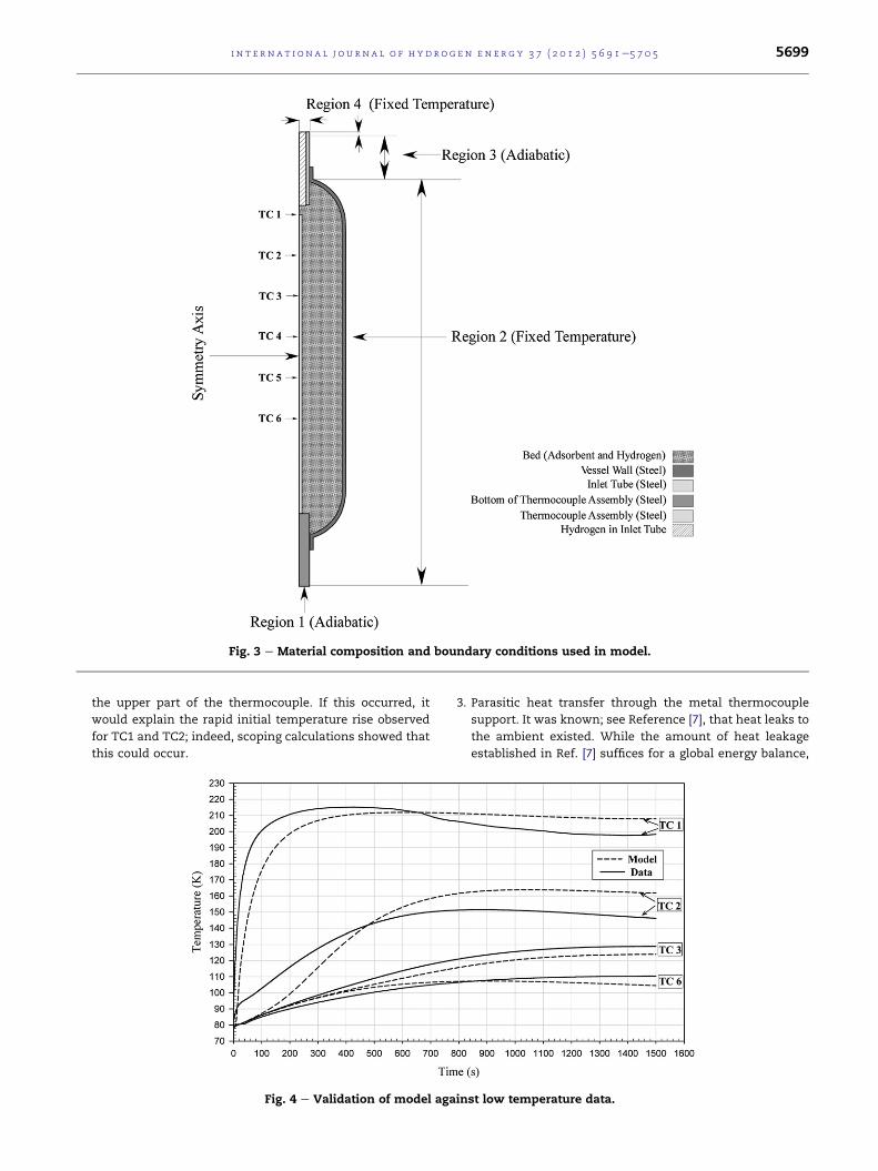
Fig. 3 e Material composition and boundary conditions used in model.
i n t e r n a t i o n a l j o u r n a l o f h y d r o g e n en e r g y 3 7 ( 2 0 1 2 ) 5 6 9 1e5 7 0 5 5699
the upper part of the thermocouple. If this occurred, it
would explain the rapid initial temperature rise observed
for TC1 and TC2; indeed, scoping calculations showed that
this could occur.
Fig. 4 e Validation of model aga
3. Parasitic heat transfer through the metal thermocouple
support. It was known; see Reference [7], that heat leaks to
the ambient existed. While the amount of heat leakage
established in Ref. [7] suffices for a global energy balance,
inst low temperature data.

i n t e rn a t i o n a l j o u r n a l o f h y d r o g e n en e r g y 3 7 ( 2 0 1 2 ) 5 6 9 1e5 7 0 55700
more precise information is required for the detailed
model.
4. Scoping calculations have shown that, as expected, the
model is quite sensitive to changes in the adsorbent
thermal conductivity. In the validationmodels, the thermal
conductivity of the adsorbent was given an approximate
fixed value of 0.2 W/m-K. It is known, however, that the
adsorbent thermal conductivity decreases with decreasing
temperature. Temperature gradients within the bed will
therefore yield non-uniform bed thermal conductivities,
which will impact heat transfer.
Total hydrogen concentrations calculated by themodel are
shown in Fig. 5. Although the model had the ability to
compute spatial pressure gradients within the vessel, it was
found that the pressure was nearly uniform during the
charging process. At 100 s, the model predicted that the
hydrogen concentration was lowest at the top of the adsor-
bent bed. This was due to the influx of gas at a temperature of
approximately 290 K, which reduced the amount of adsorbed
hydrogen at that location. As the transient progressed, the
total amount of stored hydrogen increased. However, the heat
released during the charging process resulted in elevated
temperatures, and relatively lower amounts of stored
hydrogen, in the interior of the bed. Higher hydrogen
concentrations were predicted along the cold surfaces in the
vessel, which included the tank wall and the central ther-
mocouple support. Lower temperatures occurred at the
surface of the steel thermocouple support because it provided
a path for heat transfer to the liquid nitrogen within the
Dewar.
4.2. Application
4.2.1. Storage vessel chargingThe low thermal conductivity of MaxSorb� and MOF-5�makes it difficult to employ conduction to remove heat
Fig. 5 e Hydrogen concentration profiles during the charging pr
temperature was 80 K.
released during the charging process. Enhancement of the
adsorbent thermal conductivity would either require amend-
ments, such as expanded natural graphite, or close spacing of
heat transfer surfaces to reduce the conduction transport
length. Either way, the gravimetric and volumetric capacities
of the bed would be compromised by the addition of non-
adsorbing material. An alternative method for heat removal
is passing cold hydrogen through the bed to transfer heat by
convection [8,15,16]. For this process, some hydrogen would
be adsorbed and the remainder would be cycled through the
bed and recovered, see Figs. 6e8. Because adequate hydrogen
superficial velocity is required for flow-through cooling to be
viable, the bed permeability must be high enough that the
required flow can be attained for reasonable pressure
gradients.
According to the 2017 DOE Technical Targets [3], a storage
vessel must be charged with 5 kg of available hydrogen in
3.3 min. The total amount of hydrogen available is that
recovered by transitioning the storage vessel from its initial
state at full charge to its final, “empty,” state upon return to
the fueling station. The 5 kg quantity is interpreted as the
amount of hydrogen available to supply power to propel the
vehicle. Integrated system models indicate that an additional
0.6 kg of hydrogen must be stored to power storage system
support components, such as pumps, heaters, etc. Therefore,
a total of 5.6 kg of hydrogen must be stored in 3.3 min. The
integrated system model, which employed a global energy
balance for the vessel and assumed a “nominal” rate of heat
removal, was used to estimate the volume of the storage
vessel, shown in Figs. 6e8. For this reason, the total capacity of
the vessel exceeds 5.6 kg of available hydrogen and, for more
rapid charging times, the vessel stores more than 5.6 kg of
available hydrogen. Both adsorbed and compressed gas phase
hydrogen stored in the void volume of the adsorbent are
included in the total. The adsorbents, MaxSorb� and MOF-5�,
were assumed to be in nominal powder form and occupied
a volume of 0.164 m3. Prior to charging the storage vessel was
ocess. In this figure P0 is the initial pressure and the initial

Fig. 6 e The effect of vessel wall heat capacity on charging rates for axial flow-through cooling of MaxSorb. The term
‘available hydrogen’ refers to the amount of hydrogen released upon return to the initial state.
i n t e r n a t i o n a l j o u r n a l o f h y d r o g e n en e r g y 3 7 ( 2 0 1 2 ) 5 6 9 1e5 7 0 5 5701
assumed to be at 180 K and 5 bar, which reflects its state upon
arrival at the fueling station. To enforce rapid charging of
hydrogen the vessel pressure was raised from 5 to 200 bar in
20 s and the temperature of hydrogen entering the vessel was
80 K. The average velocity of hydrogen exiting the vessel, for
the purpose of cooling, was allowed to increase from 0 to 9m/s
over a 2 s time interval, starting at 3 s after initiation of the
charging transient. The vessel dimensions and geometry are
shown in Figs. 6e8, which also show the charging rate of total
hydrogen, which includes the adsorbed hydrogen and
compressed hydrogen in the void spaces of the adsorbent.
Figs. 6 and 7 show hydrogen charging rates for a vessel
cooled by passing hydrogen axially through the adsorbent
Fig. 7 e Comparison of charging rates for axial flo
bed. Because the vessel wall participates in the transient by
way of thermal energy stored at the initial state, the effect of
the volumetric heat capacity, (rCp) was investigated. Fig. 6
shows the effect of the volumetric heat capacity of the
vessel wall on the charging of a MaxSorb� based vessel.
Reducing the volumetric heat capacity of the wall can be seen
to markedly affect the rate of hydrogen storage by reducing
the initially stored amount of thermal energy that must be
removed by convection.
Fig. 7 shows the difference in the rate of hydrogen storage
forMaxSorb� andMOF-5� based vessels, which are otherwise
identical and are charged under the same conditions. From
the plot, it can be seen thatMOF-5� chargesmore rapidly than
w-through cooling of MaxSorb and MOF-5�.

Fig. 9 e Relative contribution of pressure work and heat of
adsorption for MaxSorb� and MOF-5�. System
configuration and operating conditions are those of Fig. 7.
Fig. 8 e Comparison of charging rates for radial and axial flow-through cooling of MaxSorb.
i n t e rn a t i o n a l j o u r n a l o f h y d r o g e n en e r g y 3 7 ( 2 0 1 2 ) 5 6 9 1e5 7 0 55702
MaxSorb�. The reason for the difference is that the lower
volumetric heat capacity, (rCp) of MOF-5�, due to its lower bulk
density, results in a lower amount of stored thermal energy
and, thus, a more rapid reduction in temperature. Because the
temperature of the MOF-5� bed is reduced more quickly, the
hydrogen loading rate is increased.
Fig. 8 compares MaxSorb� charging rates for the axial
passage of cooling hydrogen through the adsorbent and for
radial passage of hydrogen through the bed. The assumed
radial flow configuration is depicted in the schematic in Fig. 8.
Here, radial hydrogen flow was achieved by passing hydrogen
through a porous rod, having a higher permeability than the
bed, along the centerline of the vessel and out through
a porous liner, composed of the same material, along the wall
of the vessel. For this radial cooling configuration, charging
was not quite as rapid as that obtained for axial flow.
4.2.2. Pressure workAs noted in References [12] and [13], pressure work can make
significant contribution to the heat released during charging.
The rate of heat generation by pressure work is
� 3TcvcvT
vPvt
(20)
The rate of heat generation due to adsorption is
� v
vt
rAds
�DUa þ na
�uH2O � uH2
���(21)
Fig. 9 shows the relative contributions of heat generation by
pressure work and heat due to adsorption for MOF-5� and
MaxSorb�, in the axial flow-through system shown in Fig. 7.
The curves in Fig. 9 show that the contribution of pressure
work to the total heat generation can be significant. The
relative significance of pressure work depends on: the ratio of
gas stored in the adsorbed phase to that in the gas phase, the
adsorbent thermodynamics and the change in pressure.
During a transient, the rate of heat transfer will control the
local temperature, which, in turn will make the ratio of pres-
sure work to adsorption heat a function of time.
Table 3 gives the total (integral) contribution of pressure
work and heat due to adsorption for the MOF-5� and

Table 3 e Contribution of pressure work and adsorption to heat generation.
Total PressureWork (MJ)
Total AdsorptionHeat (MJ)
Total Available H2
in Adsorbed Volume (kg)Total Available H2
in Gas Volume (kg)
MaxSorb� 1.39 4.81 4.57 3.15
MOF-5� 2.03 2.14 3.40 4.91
i n t e r n a t i o n a l j o u r n a l o f h y d r o g e n en e r g y 3 7 ( 2 0 1 2 ) 5 6 9 1e5 7 0 5 5703
MaxSorb� systems over the charging transient. Also
shown in Table 3 are the quantities of available
hydrogen stored in the adsorbed volume, Va, and the gas
phase volume.
4.2.3. Exhaust hydrogen for charging with flow-throughcoolingThemass of hydrogen exhaust from the vessel and its average
temperature for the charging process assumed above, are
shown in Table 4. The total mass of available hydrogen for
each case in Table 4 is shown in Figs. 6e8. To improve the
efficiency of the flow-through cooling process it is desirable to
minimize both the mass and average temperature of the
exhaust gas, or more precisely to minimize its total enthalpy.
Lower total enthalpy better facilitates mixing the exhaust
hydrogenwith cold hydrogen and using themixture to initiate
cooling and charging of another discharged vessel, which
would be at an elevated temperature upon arrival at the
fueling station.
Table 4 e Exhaust hydrogen characteristics.
Charge Time (s) Mass
MaxSorb Low Wall rCp 140
MaxSorb Nominal Wall rCp 198a
MOF-5� Low Wall rCp 95
MaxSorb Low Wall rCp Radial Cooling 155
a Had not reached full capacity.
Fig. 10 e Storage capacity and breakeve
4.2.4. Limitations on charging pressureAs noted in References [7,23], the mass of hydrogen stored on
a volumetric basis by an adsorbent exceeds that stored by
compression alone up to a particular pressure. Above this
pressure, which depends on temperature, more hydrogen is
stored by compression and the advantage of using an adsor-
bent is lost. The pressure at which storage by pure compres-
sion equals that by adsorption is called the breakeven
pressure. In hydrogen storage applications the breakeven
pressure is a design parameter used to determinewhether it is
advantageous to use an adsorbent rather than compression
alone.
Fig. 10 shows the total mass of stored hydrogen on a volu-
metric basis for MaxSorb�, MOF-5� and compression for
pressures up to 35 MPa and temperatures of 70, 80, 90 and
100 K. For the adsorbents, the concentration includes adsor-
bed hydrogen plus compressed hydrogen in the void volume.
The compressibility factor from the NIST REFPROP database
[6] is used in all calculations for this figure and the adsorbent
of Exhaust H2 (kg) Average Exhaust H2 Temperature (K)
17.9 133.67
27.51 120.06
11.61 132.42
19.58 137.49
n curves for MOF-5� and MaxSorb.

i n t e rn a t i o n a l j o u r n a l o f h y d r o g e n en e r g y 3 7 ( 2 0 1 2 ) 5 6 9 1e5 7 0 55704
storage is based on the DubnineAstakhov parameters for each
of the adsorbents. For temperatures above 70 K MOF-5� has
higher breakeven pressures than MaxSorb�. The volumetric
hydrogen storage capacity for MaxSorb� exceeds that of MOF-
5� until the pressure approaches the MaxSorb� breakeven
pressure.
5. Summary and conclusions
A general model was developed for adsorbent based hydrogen
storage systems. The model was based on systematically
derived conservation equations, employed modified Dubi-
nineAstakhov adsorbent thermodynamics and used real gas
properties. The model may readily be applied to a variety of
adsorbents, vessel configurations and operating conditions;
including charging, discharging and dormancy. System
components, including structures and heat transfer devices
can be incorporated directly into the model as part of the heat
transfer and flow calculations. Calculated parameters include
time and spatially dependent pressure, temperature, molar
concentrations of hydrogen, the components of gas velocity,
gas concentration and/or density. In addition, the model can
compute algebraic combinations, integrals and time or spatial
derivatives of the above variables. The ability to manipulate
dependent variables is essential for evaluation of the perfor-
mance of storage systemdesigns and for scale-up of prototype
tests.
Although the hydrogen adsorption model compared
reasonablywell with data, therewere discrepancies attributed
to experimental measurements andmaterial property data. In
the comparisons between themodel and data, no attemptwas
made to “tune” input parameters to obtain a better fit.
Refinements to the experimental rig will be made to better
control inlet hydrogen temperature and measure the surface
temperature of the pressure vessel that contains the adsor-
bent. Specifically, the volume of the Dewarwill be increased to
ensure that the pressure vessel is always completely sur-
rounded by liquid nitrogen, additional thermocouples will be
used to more completely monitor vessel surface tempera-
tures, and the inlet hydrogen temperature will be better
controlled through the use of a dedicated heat exchanger.
Further, the thermal conductivity of the adsorbent bed will be
more accurately measured.
For the flow-through cooling method, the model was used
to evaluate:
1. Concept viability
2. Effect of vessel heat capacity and type of adsorbent
3. Effect of radial or axial flow designs
4. Relative importance of pressure work and heat release due
to adsorption
5. State of exhaust hydrogen, which is a factor in the effi-
ciency of the charging process.
Calculations for the flow-through system demonstrate the
need to control the thermal contact between the adsorbent
bed and the vessel wall and/or the heat capacity of the wall. It
was found that, under certain conditions, pressurework could
be a significant contributor to the total energy released, see
Fig. 9 and Table 3. At higher temperatures less gas is stored by
adsorption. Therefore, during the charging process, the frac-
tion of the total energy released due to pressure work
increases with increasing temperature.
At temperatures above 70 K the breakeven pressures for
MOF-5� exceed those for MaxSorb�. On a volumetric basis,
MaxSorb� stores more hydrogen than MOF-5� until the
MaxSorb� breakeven pressure is approached. However, the
bulk density of MOF-5� is half that of MaxSorb�. Hence, the
capacity of MOF-5� is greater on a mass basis. Recent
unpublished work suggests that MOF-5� can be compacted
without significant loss of hydrogen storage capacity. If so, it
may be possible for its volumetric capacity to be significantly
improved.
Acknowledgments
This document was prepared in conjunction with work
accomplished under Contract No. DE-AC09-08SR22470 with
the U.S. Department of Energy.
Disclaimer
This work was prepared under an agreement with and funded
by the U.S. Government. Neither the U. S. Government or its
employees, nor any of its contractors, subcontractors or their
employees, makes any express or implied: 1. warranty or
assumes any legal liability for the accuracy, completeness, or
for the use or results of such use of any information, product,
or process disclosed; or 2. representation that such use or
results of such use would not infringe privately owned rights;
or 3. endorsement or recommendation of any specifically
identified commercial product, process, or service. Any views
and opinions of authors expressed in this work do not
necessarily state or reflect those of the United States
Government, or its contractors, or subcontractors.
r e f e r e n c e s
[1] Aceves SM, Berry GD, Martinez-Frias J, Espinosa-Loza F.Vehicular storage of hydrogen in insulated pressure vessels.Int J Hydrogen Energy 2006;31:2274e83.
[2] Aceves SM, Espinosa-Loza F, Ledesma-Orozco E, Ross TO,Weisberg AH, Brunner TC, et al. High-density automotivehydrogen storage with cryogenic capable pressure vessels.Int J Hydrogen Energy 2010;35:1219e26.
[3] DOE targets for onboard hydrogen storage systems forlight-duty vehicles, rev. 4.0. Available from:http://www1.eere.energy.gov/hydrogenandfuelcells/storage/pdfs/targets_onboard_hydro_storage.pdf [accessed 12.12.11].
[4] Richard M-A, Benard P, Chahine R. Gas adsorption process inactivated carbon over a wide temperature range above thecritical point. Part 1: modified DubinineAstakhov model.Adsorption 2009;15:43e51.
[5] Richard M-A, Benard P, Chahine R. Gas adsorption process inactivated carbon over a wide temperature range above thecritical point. Part 2: conservation of mass and energy.Adsorption 2009;15:53e63.

i n t e r n a t i o n a l j o u r n a l o f h y d r o g e n en e r g y 3 7 ( 2 0 1 2 ) 5 6 9 1e5 7 0 5 5705
[6] Lemmon EW, Huber ML, McLinden MO. NIST StandardReference Database 23: reference fluid thermodynamic andtransport properties-REFPROP, Version 8.0. Gaithersburg:National Institute of Standards and Technology, StandardReference Data Program; 2007.
[7] Richard M-A, Cossement D, Chandonia P-A, Chahine R,Mori D, Hirose K. Preliminary evaluation of the performanceof an adsorption-based hydrogen storage system. AIChE J2009;11:2985e96.
[8] Kumar VS, Raghunatahan K, Kumar S. A lumped-parametermodel for cryo-adsorber hydrogen storage tank. Int JHydrogen Energy 2009;34:5466e75.
[9] Kumar VS, Kumar S. Generalized model development fora cryo-adsorber and 1-D results for the isobaric refuelingperiod. Int J Hydrogen Energy 2010;35:3598e609.
[10] Bird RB, Stewart WE, Lightfoot EN. Transport phenomena.New York, NY: John Wiley & Sons, Inc; 1960.
[11] Ghosh I, Naskar S, Bandyopadhyay SS. Cryosorption storageof gaseous hydrogen for vehicular application e a conceptualdesign. Int J Hydrogen Energy 2010;35:161e8.
[12] Hermosilla-Lara G, Momen G, Marty PH, Le Neindre B,Hassouni K. Hydrogen storage by adsorption on activatedcarbon: investigation of the thermal effects during thecharging process. Int J Hydrogen Energy 2007;32:1542e53.
[13] Momen G, Hermosilla G, Michau A, Pons M, Firdaus M,Marty PH, et al. Experimental and numerical investigation ofthe thermal effects during hydrogen charging in a packedbed storage tank. Int J Hydrogen Energy 2009;52:1495e503.
[14] Zhan L, Li KX, Zhang R. Improvements of the DA equation forapplication in hydrogen adsorption at supercriticalconditions. J Supercrit Fluids 2004;28:37e45.
[15] Paggiaro R, Michl F, Benard P, Polifke W. Cryo-adsorptivehydrogen storage on activated carbon, II: investigation of thethermal effects during filling at cryogenic temperatures. Int JHydrogen Energy 2010;35:648e59.
[16] Schutz W, Michl F, Polifke W, Paggiaro R. Storage systems forstoring a medium and method for loading a storage systemwith a storage medium an emptying the same there from.Patent (WO/2005/044454), http://www.wipo.int/pctdb/en/wo.jsp?wo¼2005044454; 2005.
[17] Xiao J, Tong l, Deng C, Benard P, Chahine R. Simulation ofheat and mass transfer in activated carbon tank forhydrogen storage. Int J Hydrogen Energy 2010;35:8106e16.
[18] Vasiliev LL, Kanonchik LE. Activated carbon fibres andcomposites on its base for high performance hydrogenstorage system. Chem Eng Sci 2010;65:2586e95.
[19] Pyda M, Bartkowiak M, Wunderlich B. Computation of heatcapacities of solids using a general Tarasov equation. JThermal Analysis 2009;52(2):631e56.
[20] Comsol Multiphysics� 3.5a version 3.5.0.606. Copyright1998e2008. Comsol AB.
[21] Critoph RE, Turner L. Heat transfer in granular activatedcarbon beds in the presence of adsorbable gases. Int J HeatMass Trans 1995;38(9):1577e85.
[22] Huang BL, Ni Z, Millward A, McGaughey AJH, Uher C,Kaviany M, et al. Thermal conductivity of a metal organicframework (MOF-5): Part II. Measurement. Int J Heat MassTrans 2007;50(3e4):405e11.
[23] Chahine R, Richard M-A, Cossement D. H2 storage innanoporous structures. Presentation, Task 22 IEA HIA ExpertMeeting; 6e10 October 2008. Villa Mondragone, CastelliRomani, Italy.