Modeling Errors and Accuracy -...
12
1 MAE 456 Finite Element Analysis Modeling Errors and Accuracy And checking the results! MAE 456 Finite Element Analysis Sources of Error Causes of incorrect results: 1. Mistakes (e.g., forgetting a load) 2. Errors A. Modeling Error (due to simplifying assumptions in mathematical model such as when using beam elements we assume that the cross-sections stay planar and do not change shape) B. Discretization Error (i.e., due to piecewise approximation which can be minimized by using higher order shape functions or smaller elements) C. Numerical Error (due to limited number of significant digits maintained by computer) 2
-
Upload
nguyenthuan -
Category
Documents
-
view
232 -
download
0
Transcript of Modeling Errors and Accuracy -...
1
MAE 456 Finite Element Analysis
Modeling Errors and Accuracy
And checking the results!
MAE 456 Finite Element Analysis
Sources of Error
Causes of incorrect results:
1. Mistakes (e.g., forgetting a load)
2. Errors
A. Modeling Error (due to simplifying assumptions
in mathematical model such as when using beam elements we
assume that the cross-sections stay planar and do not change shape)
B. Discretization Error (i.e., due to piecewise
approximation which can be minimized by using higher order shape
functions or smaller elements)
C. Numerical Error (due to limited number of
significant digits maintained by computer)
2

2
MAE 456 Finite Element Analysis
1. Mistakes
• Common mistakes that will cause a singular Kmatrix (and therefore no results):– νννν = 0.5 in a plain strain, axisymmetric or 3D solid
element
– E = 0 in an element
– No supports, or insufficient supports
– Part of the model is a mechanism
– Large stiffness differences
– In an element with stress-stiffening, negative stiffening has reduced the stiffness to zero
– In nonlinear analysis, supports or connections have reached zero stiffness
3
MAE 456 Finite Element Analysis
Common Mistakes
• Insufficient supports will allow rigid body
motion.
(The stiffness matrix will be singular.)
X
Y
X
Y
4

3
MAE 456 Finite Element Analysis
Common Mistakes
• Mistakes that may go unnoticed:
– Incorrect element data (e.g., wrong thickness, beam
cross-section, cross-section dimension, beam orientation)
– Supports wrong in location, type or direction
– Loads wrong in location, type, direction or magnitude
– Units mix-up
– A force or mesh defined twice and/or on different duplicated geometry
– Connections not working as intended (e.g. beam
element connected to plane element does not transfer moment)5
MAE 456 Finite Element Analysis
Common Mistakes
• Effect of wrong support types:
Each of these will result in different displacements, strains
and stresses.
X
Y
X
Y
X
Y
X
Y
X
Y
X
Y
X
Y
X
Y
6

4
MAE 456 Finite Element Analysis
2. A. Modeling Error
• To do a proper FE analysis, the analyst must understand how the structure is likely to behave and how elements are able to behave.
• E.g., if the analyst knows the displacement varies linearly,
4-node quad. elements will work, but if they vary
quadratically, 8-node quad. elements must be used.
7
Images from R. Cook, et al. Concepts and Applications of Finite Element Analysis, 1996.
MAE 456 Finite Element Analysis
Element Tests
• Use a patch test or single element test to
determine how an element works under
different circumstances.
• Study different states of stress and strain.
8
Images from R. Cook, et al. Concepts and Applications of Finite Element Analysis, 1996.

5
MAE 456 Finite Element Analysis
Element Tests
• Study the effects of element distortions and
changes in element size.
9
Images from R. Cook, et al. Concepts and Applications of Finite Element Analysis, 1996.
MAE 456 Finite Element Analysis
Test Cases
• Established test cases from:
– research literature
– National Agency for Finite Element Methods and Standards
– software documentation
can be used to check the accuracy of elements and models.
• “Pilot studies” can be used to check software capabilities.
10Images from R. Cook, et al. Concepts and Applications of Finite Element Analysis, 1996.

6
MAE 456 Finite Element Analysis
2. B. Discretization Error
• If a mesh is repeatedly refined, will the results converge to a solution?
• Yes, if the elements used pass the “patch” test.
11
Images from R. Cook, et al. Concepts and Applications of Finite Element Analysis, 1996.
MAE 456 Finite Element Analysis
Convergence Requirements
• In a patch test, the FE model must have:
– A simple arrangement of elements with one internal node
– Supports sufficient to stop rigid body motion
– Work equivalent loads consistent with a constant state of stress (and strain)
• To pass the test, the results must exactly
represent the correct constant stress (and
strain), within numerical error.
12
7
MAE 456 Finite Element Analysis
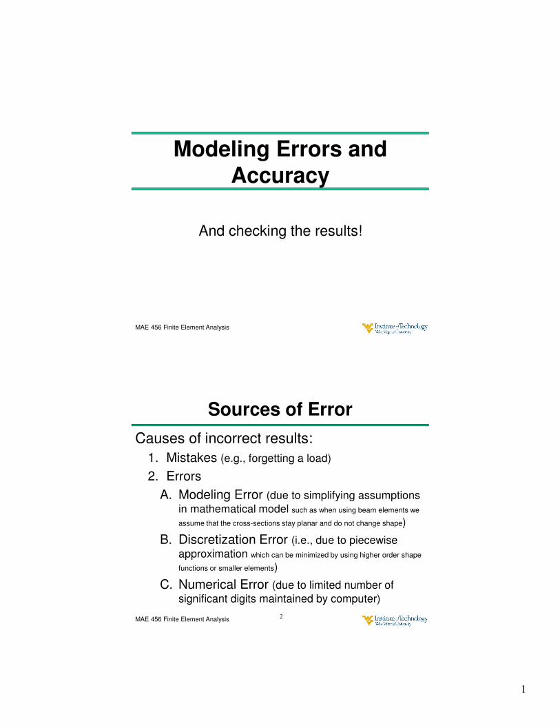
Mesh Refinement
• There are three ways to refine a mesh:
1. h-refinement (changing the element size)
2. p-refinement (changing to elements with higher
order polynomial interpolations)
3. r-refinement (moving nodes)
13
Images from R. Cook, et al. Concepts and Applications of Finite Element Analysis, 1996.
MAE 456 Finite Element Analysis
Mesh Refinement
• A combination of these methods can also
be used.
• The mesh should be refined until
convergence is achieved (i.e., the results change
very little from the previous refinement).
• Some software automates the refinement
process (adaptive meshing).
14
Images from R. Cook, et al. Concepts and Applications of Finite Element Analysis, 1996.

8
MAE 456 Finite Element Analysis
Error Measures
One approach to error estimation is to assume that the nodal averaged stress (σ*) is correct and the error (σE) is given at every point by the difference from the element stress (σ).
15
Images from R. Cook, et al. Concepts and Applications of Finite Element Analysis, 1996.
MAE 456 Finite Element Analysis
Error Measures and Adaptivity
• An Automated Adaptive Solution proceeds
by refining the mesh, in elements where the
error is large, until the maximum error is
below some limit.
16
Images from R. Cook, et al. Concepts and Applications of Finite Element Analysis, 1996.

9
MAE 456 Finite Element Analysis
2. C. Numerical Error
• Rounding errors will accumulate (more so in
large DOF models)
• Adding very small numbers to big numbers
is even more problematic (i.e. in “Stiff Systems”)
17
MAE 456 Finite Element Analysis
Numerical Error – “Stiff” Systems
• If k1 >> k2,
• If k2 >> k1,
18
10
MAE 456 Finite Element Analysis
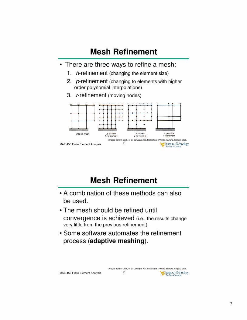
Susceptibility to Ill-Conditioning
• Large cross-coupling stiffness coefficients will cause problems
• Having membrane stiffness ≫ bending stiffness will cause problems.
19
MAE 456 Finite Element Analysis
3. Checking the Model (before solving)
• Checking done automatically by software– Model has mesh and boundary conditions are applied.
– All mesh and boundary condition properties have been provided.
– Element aspect ratios and corner angles too small or too large.
– Element is too warped.
– Poisson’s ratio too large.
– Curved shell element spans too great an arc.
• Specific checks that can be requested• Coincident nodes (Are they supposed to be one node?)
20

11
MAE 456 Finite Element Analysis
Checking the Model (before solving)
• Checking done by Analyst
– Everything meshed properly?
– All required loads/support conditions applied?
– Double-check material/shell/beam properties
21
Image from R. Cook, et al. Concepts and Applications of Finite Element Analysis, 1996.
MAE 456 Finite Element Analysis
Checking the Results (after solving)
• Results should be checked so that:
– Deflections obey intended support conditions.
– Deflections are symmetric in a symmetric problem.
– Where a gap closes the parts do not overlap.
– Support reactions agree with static calculations.
– There are no large displacements that cause force
directions to change (use a nonlinear analysis in this case).
22
Images from R. Cook, et al. Concepts and Applications of Finite Element Analysis, 1996.

12
MAE 456 Finite Element Analysis
Checking the Results• Note that deflections may only appear large
because of the exaggeration factor used to display the deflections.
• Stresses should be checked that:
• Stress contours are normal to planes of symmetry
• One of the principle stresses should be zero at an unloaded boundary or equal to –p if there is a pressure p loading condition.
23
Images from R. Cook, et al. Concepts and Applications of Finite Element Analysis, 1996.
MAE 456 Finite Element Analysis
Checking the Results
• When checking stresses note that:
– Unaveraged stresses should be checked.
– Confirm that the displayed stress is the one you want to look at (i.e., principle stress vs. shear
stress vs. von Mises stress, etc.)
– Stresses may be in local or global coordinates
– Stresses may be for the upper, lower or mid-surface of beam and shell elements.
24