Modeling, Control and Optimization of a New Swimming ... · Modeling, Control and Optimization of a...
7
Abstract— This article deals with the study of a new swimming microrobot behavior using an analytical investigation. The analyzed microrobot is associated by a spherical head and hybrid tail. The principle of modeling is based on solving of the coupled elastic/fluidic problems between the hybrid tail’s deflections and the running environment. In spite of the resulting nonlinear model can be exploited to enhance both the sailing ability and also can be controlled in viscous environment using nonlinear control investigations. The applications of the micro-robot have required the precision of control for targeting the running area in terms of response time and tracking error. Due to these limitations, the Flatness-ANFIS based control is used to ensure a good control behavior in hazardous environment. Our control investigation is coupled the differential flatness and adaptive neuro-fuzzy inference techniques, in which the flatness is used to planning the optimal trajectory and eliminate the nonlinearity effects of the resulting model. In other hand, the neuro-fuzzy inference technique is used to build the law of control technique and minimize the dynamic error of tracking trajectory. In particular, we deduct from a non linear model to an optimal model of the design parameter’s using Multi-Objective genetic algorithms (MOGAs). In addition, Computational fluid dynamics modeling of the microrobot is also carried out to study the produced thrust and velocity of the microrobot displacement taking into account the fluid parameters. Our analytical results have been validated by the recorded good agreement between the numerical and analytical results. Index Terms— ANFIS, Fuzzy computation, IPCM, Flatness, Control, Microrobotics, Swimming. I. INTRODUCTION owadays, the microrobots take the lion's share of the different research fields of interest. They are increasingly important necessities for precision applications due to their speed in terms of response time and controllability in dangerous environments [1-6]. The surgical assistance microrobots are regularly used in operating rooms. Currently, the researchers have developed miniature endoscopic capsule robot able to explore intestinal conduits, arteries or veins, for assist the surgeon in his diagnosis, based on the entirety of Manuscript received 30 December, 2015. F. Srairi is with Department of Electronics, University of Batna, 05000, Algeria (e-mail:[email protected]). L. Saidi is with Department of Electronics, University of Batna, 05000, Algeria (e-mail:[email protected]). F. Djeffal is with the Laboratory of Advanced Electronic, Department of Electronics, LEPCM, University of Batna, 05000, Algeria (e-mail: [email protected], [email protected]) m. meguellati is with the Department of Electronics, University of Batna, 05000, Algeria (e-mail: m_meguellati@ yahoo.fr). submicron embedded sensors [7,8], or in military applications such as the description of the nuclear area or define a large moving targets [9-13]. Recently, many researches and practices are developed including new materials and design aspects [1-5]. Most of these microrobots used a huge number of parts, which leads to microrobot behavior degradation in terms of complexity and fabrication cost. In other hand, several investigations have been conducted on microrobot systems, which are not based on the biomimetic philosophy. New method was introduced by Chang et al [1], in this method; an external magnetic field is applied to rotate a small ferromagnetic screw in the liquid. However, speed limitation is the main disadvantage of this microrobot. In this work, we have modeled a new swimming microbobot design, which is compounded by a spherical head and hybrid tail. The principle of modeling is based on solving the coupled elastic/fluids problems between the hybrid tail’s vibrations and running environment. Where the motion of the hybrid tail is strongly created by an active joint made in polymer ionic metal (IPCM) and the initial motion of the microrobot is excited by a field magnetic outcome of the coil set up at the head and occupied a half of the head's vacuum. The use of coil in head allows us to ensure a better controllability and stability of the microrobot device [14]. Despite of nonlinear model result from the analytical modeling of our design and due to their ambiguous applications, it is required fast and high strategy to achieve the target. The control strategy presents a main topic in microrobot field. Therefore, the aim of our control strategy is to improve the performances of the device in running environment, in terms of tracking trajectory and time response. Our strategy is based on coupling between the differential flatness and Neuro fuzzy inference (ANFIS) techniques. In which, the use of flatness technique allows us to eliminate the nonlinearity of the analytical model and generates an optimal trajectory. In other hand, the ANFIS strategy is used to build the law control to ensure a good tracking trajectory and minimize the dynamic error basing on back propagate method [15-16]. The analytical modeling is completed by computational fluid dynamic (CFD) modeling because of their complementary nature. Therefore, the use of CFD modeling gives the kinematic patterns of the active joint. So, it’s taken much time to capture some nonlinear and complex effects such that vortices. This latter is ignored in analytical modeling. The investigation is focused on one hybrid tail attached to a body [1][17-21]. The numerical results indicate that good agreement is achieved between the analytical Modeling, Control and Optimization of a New Swimming Microrobot Design F. Srairi, L. Saidi, F. Djeffal and M. Meguellati N Engineering Letters, 24:1, EL_24_1_15 (Advance online publication: 29 February 2016) ______________________________________________________________________________________
Transcript of Modeling, Control and Optimization of a New Swimming ... · Modeling, Control and Optimization of a...

Abstract— This article deals with the study of a new swimming microrobot behavior using an analytical investigation. The analyzed microrobot is associated by a spherical head and hybrid tail. The principle of modeling is based on solving of the coupled elastic/fluidic problems between the hybrid tail’s deflections and the running environment. In spite of the resulting nonlinear model can be exploited to enhance both the sailing ability and also can be controlled in viscous environment using nonlinear control investigations. The applications of the micro-robot have required the precision of control for targeting the running area in terms of response time and tracking error. Due to these limitations, the Flatness-ANFIS based control is used to ensure a good control behavior in hazardous environment. Our control investigation is coupled the differential flatness and adaptive neuro-fuzzy inference techniques, in which the flatness is used to planning the optimal trajectory and eliminate the nonlinearity effects of the resulting model. In other hand, the neuro-fuzzy inference technique is used to build the law of control technique and minimize the dynamic error of tracking trajectory. In particular, we deduct from a non linear model to an optimal model of the design parameter’s using Multi-Objective genetic algorithms (MOGAs). In addition, Computational fluid dynamics modeling of the microrobot is also carried out to study the produced thrust and velocity of the microrobot displacement taking into account the fluid parameters. Our analytical results have been validated by the recorded good agreement between the numerical and analytical results.
Index Terms— ANFIS, Fuzzy computation, IPCM, Flatness, Control, Microrobotics, Swimming.
I. INTRODUCTION
owadays, the microrobots take the lion's share of the different research fields of interest. They are increasingly
important necessities for precision applications due to their speed in terms of response time and controllability in dangerous environments [1-6]. The surgical assistance microrobots are regularly used in operating rooms. Currently, the researchers have developed miniature endoscopic capsule robot able to explore intestinal conduits, arteries or veins, for assist the surgeon in his diagnosis, based on the entirety of
Manuscript received 30 December, 2015.
F. Srairi is with Department of Electronics, University of Batna, 05000, Algeria (e-mail:[email protected]).
L. Saidi is with Department of Electronics, University of Batna, 05000, Algeria (e-mail:[email protected]).
F. Djeffal is with the Laboratory of Advanced Electronic, Department of Electronics, LEPCM, University of Batna, 05000, Algeria (e-mail: [email protected], [email protected])
m. meguellati is with the Department of Electronics, University of Batna, 05000, Algeria (e-mail: m_meguellati@ yahoo.fr).
submicron embedded sensors [7,8], or in military applications such as the description of the nuclear area or define a large moving targets [9-13].
Recently, many researches and practices are developed including new materials and design aspects [1-5]. Most of these microrobots used a huge number of parts, which leads to microrobot behavior degradation in terms of complexity and fabrication cost. In other hand, several investigations have been conducted on microrobot systems, which are not based on the biomimetic philosophy. New method was introduced by Chang et al [1], in this method; an external magnetic field is applied to rotate a small ferromagnetic screw in the liquid. However, speed limitation is the main disadvantage of this microrobot.
In this work, we have modeled a new swimming microbobot design, which is compounded by a spherical head and hybrid tail. The principle of modeling is based on solving the coupled elastic/fluids problems between the hybrid tail’s vibrations and running environment. Where the motion of the hybrid tail is strongly created by an active joint made in polymer ionic metal (IPCM) and the initial motion of the microrobot is excited by a field magnetic outcome of the coil set up at the head and occupied a half of the head's vacuum. The use of coil in head allows us to ensure a better controllability and stability of the microrobot device [14].
Despite of nonlinear model result from the analytical modeling of our design and due to their ambiguous applications, it is required fast and high strategy to achieve the target. The control strategy presents a main topic in microrobot field. Therefore, the aim of our control strategy is to improve the performances of the device in running environment, in terms of tracking trajectory and time response. Our strategy is based on coupling between the differential flatness and Neuro fuzzy inference (ANFIS) techniques. In which, the use of flatness technique allows us to eliminate the nonlinearity of the analytical model and generates an optimal trajectory. In other hand, the ANFIS strategy is used to build the law control to ensure a good tracking trajectory and minimize the dynamic error basing on back propagate method [15-16].
The analytical modeling is completed by computational fluid dynamic (CFD) modeling because of their complementary nature. Therefore, the use of CFD modeling gives the kinematic patterns of the active joint. So, it’s taken much time to capture some nonlinear and complex effects such that vortices. This latter is ignored in analytical modeling. The investigation is focused on one hybrid tail attached to a body [1][17-21]. The numerical results indicate that good agreement is achieved between the analytical
Modeling, Control and Optimization of a New Swimming Microrobot Design
F. Srairi, L. Saidi, F. Djeffal and M. Meguellati
N
Engineering Letters, 24:1, EL_24_1_15
(Advance online publication: 29 February 2016)
______________________________________________________________________________________

modeling and CFD one in many points of kinematic patterns of active joint.
The remainder of this work is organized as follows: In section II we present the analytical model of swimming microrobot. The control strategy is presented in section III. The CFD modeling is discussed in section IV. In Section V, we present the obtained results, highlighting, the comparison between the analytical and CFD investigations and the MOGA-based optimization is presented too. We provide concluding and some remarks for future work in Section V.
II. PRINCIPE OF THE MODELING
The structure of the investigated microrobot is illustrated in fig.1 as it is shown from this figure, our microrobot design is compound by a spherical head and a hybrid flexible tail. The tail has two IPCM joints and two passive plates as links. The plates are assumed to be rigid but thin and light. The volume of the head is considered as a vacuum sphere for placed the coil, drugs and sensors. The coil occupies 60% to provide the initial driving force, and the remainder 40% of the volume reserved for drugs and sensors.
)cos(j)sin(iw
)sin(j)cos(ir
Figure 1. Cross sectional view of our proposed microrobot design with a
description of the tail.
The governing equation for the dynamic deflection
function w(X,t) of the tail performing flexural oscillations is :
)t,X(FX
)t,X(W
X
)t,X(WEI
2
2
4
4
(1)
where E presents the Young’s modulus, I is the moment of inertial of the tail, µ is the mass per unit length of the Tail, F is the external applied force per unit length, x is the spatial coordinate along the length of the tail, and t is time. The boundary conditions of (1) are the usual clamped and free end conditions.
0X
)t,X(W
X
)t,X(W
X
)t,X(W)t,x(W
X
)t,X(W
X
)t,X(W
X
)t,X(W)t,x(W
0t,LX3
3
2
2
0X3
3
2
2
where L is the length of the tail (see Fig. 1). For a
cantilever tail moving in a fluid, the external applied load F(X,t) can be calculate as:
))t(sin()w(4
)t,X(F fw (3)
where w presents the density of fluid and )w( is the
hydrodynamic function which is obtained from the solution of Navier Stokes Equation:
,0U ,uiwUP 2 (4)
Where U presents the velocity field, P is the pressure, ,
are the density and viscosity of the fluid, respectively.
Substituting (3) into (1) and rearranging we find:
))t(sin(EI
A
X
)t,X(Wa
X
)t,X(W4
4
2
2
(5)
With fw )w(4
A , EI
a
Applying the above mentioned boundary conditions we obtained the following expression of 2-D tail’s deflection W(X, t):
55242
32
222
10.6361.710.3930.2.a10.8048.4.a
A8
1Xt6728.0)t.7543.6X(
a
16207.45Exp
94948.a
1
a8928.47()tw2cos(A8
1X)7284.6a0032.0X0249.0
t4458.459.3a1819.0tAw4
1w
2
1)t,X(W
The lateral velocity of the tail can be calculated using 2-D
tail’s deflection W(X, t), as:
2
wD
2
z
)t,z(wmSC
t
)t,z(wm
U
(7)
The expression of Thrust force Fth is given by:
BMVSUC
F mwD
th
2
2
(8)
where m is the magnetic ratio, m is the virtual mass
density at z=L expressed as w2cS
4
1m , with Sc presents
the width of the tail at the end z=L, S and CD are the wetted surface area and drag coefficient, respectively.
III. NUMERICAL MODELING
The CFD modeling allows us to solve the 3D Navier-stocks equation using finite element method, where the flow is considered laminar. The structure is modeled as a cylindrical channel containing the microrobot design, to calculate the unsteady solution the dynamic mesh is adopted, while the microrobot’s volume creates other moving conditions with the fluid. The all surfaces of the channel are defined as a wall with no slip conditions and a mesh tetrahedral uniform and fine is used to grid the structure. To make the precise of the solution and close the reality the size of the channel is chosen as (15x10-3 µm of radius and 30x10-3 µm), in which the volume is mashed as 12, nodes 125, and faces 65 cells, where the
w
B2
w
r/2 w 1L
w 1d
w
i
w
j
w
r
w
w
U w(z,t)
α
w
B1
Joint
F1
FB
Link
Engineering Letters, 24:1, EL_24_1_15
(Advance online publication: 29 February 2016)
______________________________________________________________________________________
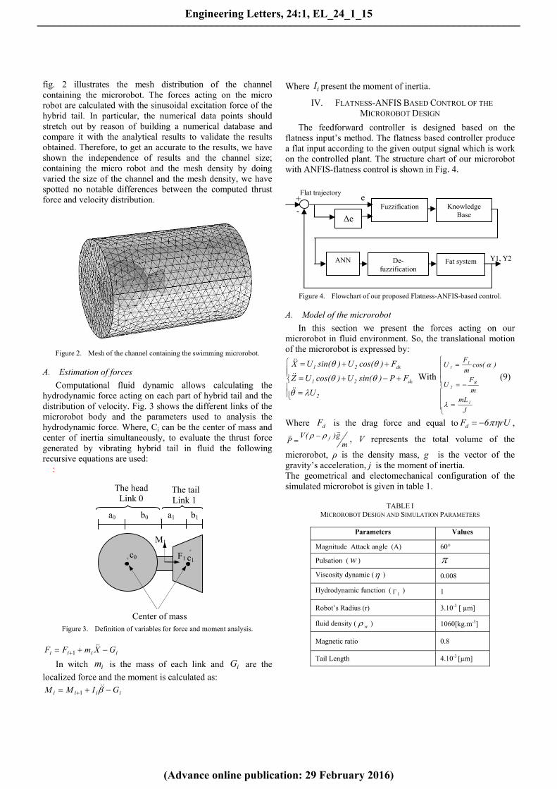
fig. 2 illustrates the mesh distribution of the channel containing the microrobot. The forces acting on the micro robot are calculated with the sinusoidal excitation force of the hybrid tail. In particular, the numerical data points should stretch out by reason of building a numerical database and compare it with the analytical results to validate the results obtained. Therefore, to get an accurate to the results, we have shown the independence of results and the channel size; containing the micro robot and the mesh density by doing varied the size of the channel and the mesh density, we have spotted no notable differences between the computed thrust force and velocity distribution.
Figure 2. Mesh of the channel containing the swimming microrobot.
A. Estimation of forces
Computational fluid dynamic allows calculating the hydrodynamic force acting on each part of hybrid tail and the distribution of velocity. Fig. 3 shows the different links of the microrobot body and the parameters used to analysis the hydrodynamic force. Where, Ci can be the center of mass and center of inertia simultaneously, to evaluate the thrust force generated by vibrating hybrid tail in fluid the following recursive equations are used:
:
Figure 3. Definition of variables for force and moment analysis.
iiii GXmFF
1
In witch im is the mass of each link and iG are the
localized force and the moment is calculated as:
iiii GIMM 1
Where iI present the moment of inertia.
IV. FLATNESS-ANFIS BASED CONTROL OF THE
MICROROBOT DESIGN
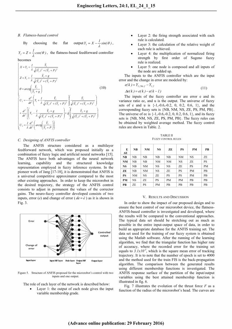
The feedforward controller is designed based on the flatness input’s method. The flatness based controller produce a flat input according to the given output signal which is work on the controlled plant. The structure chart of our microrobot with ANFIS-flatness control is shown in Fig. 4.
Figure 4. Flowchart of our proposed Flatness-ANFIS-based control.
A. Model of the microrobot
In this section we present the forces acting on our microrobot in fluid environment. So, the translational motion of the microrobot is expressed by:
2
dz21
dx21
U
FP)sin(U)cos(UZ
F)cos(U)sin(UX
With
J
mLm
FU
)cos(m
FU
1
B2
11
(9)
Where dF is the drag force and equal to rU6Fd ,
mg)(V
P f
, V represents the total volume of the
microrobot, ρ is the density mass, g is the vector of the gravity’s acceleration, j is the moment of inertia. The geometrical and electomechanical configuration of the simulated microrobot is given in table 1.
TABLE I MICROROBOT DESIGN AND SIMULATION PARAMETERS
Parameters Values
Magnitude Attack angle (A) 60°
Pulsation ( w )
Viscosity dynamic ( ) 0.008
Hydrodynamic function (1 ) 1
Robot’s Radius (r) 3.10-3 [ µm]
fluid density ( w ) 1060[kg.m-3]
Magnetic ratio 0.8
Tail Length 4.10-3 [µm]
Fuzzification
Δe
Fat system
Knowledge Base
ANN De-fuzzification
e +-
Y1, Y2
Flat trajectory
a0 b0 w a1 b1
w c0
w
c1
Center of mass
The head
Link 0
The tail Link 1
M1
F1
Engineering Letters, 24:1, EL_24_1_15
(Advance online publication: 29 February 2016)
______________________________________________________________________________________
B. Flatness-based control
By choosing the flat output )sin(1
XY1
,
)cos(1
ZY2
, the flatness-based feedforward controller
becomes
PY
Yarctg
dt
d1U
)PY()Y(
gYg
)PY()Y(
gY1Y
dt
d
)PY()Y(
Y
)PY()Y(
Y1Y
dt
dU
gY
Yarctg
)PY()Y(
gY1YZ
)PY()Y(
Y1YX
2
12
2
2
22
21
2
22
21
222
2
22
21
1
22
21
112
2
1
2
1
22
21
22
22
21
11
(10)
C. Designing of ANFIS controller
The ANFIS structure considered as a multilayer feedforward network, which was proposed initially as a combination of fuzzy logic and artificial neural networks [15]. The ANFIS have both advantages of the neural network learning, capability and the structured knowledge representation employed in fuzzy inference systems. In the pioneer work of Jang [17-18], it is demonstrated that ANFIS is a universal competitive approximator compared to the most other existing approaches. In order to keep the microrobot in the desired trajectory, the strategy of the ANFIS control consists to adjust in permanent the values of the corrector gains. The neuro-fuzzy controller developed consists of two inputs, error (e) and change of error ( ede ) as it is shown in Fig. 3.
Figure 5. Structure of ANFIS proposed for the microrobot’s control with two inputs and one output.
The role of each layer of the network is described below: Layer 1: the output of each node gives the input
variable membership grade.
Layer 2: the firing strength associated with each rule is calculated.
Layer 3: the calculation of the relative weight of each rule is achieved.
Layer 4: the multiplication of normalized firing strength by first order of Sugeno fuzzy rule is realized.
Layer 5: one node is composed and all inputs of the node are added up.
The inputs to the ANFIS controller which are the input error and the change in error are modeled by:
)1k(e)k(e)k(e
YY)k(e 2,1fRe2,1
(11)
The inputs of the fuzzy controller are error e and its variance ratio ec, and u is the output. The universe of fuzzy sets of e and u is {-1,-0.6,-0.2, 0, 0.2, 0.6, 1}, and the corresponding fuzzy sets is {NB, NM, NS, ZE, PS, PM, PB}. The universe of ec is {-1,-0.6,-0.2, 0, 0.2, 0.6, 1}, and its fuzzy sets is {NB, NM, NS, ZE, PS, PM, PB}. The fuzzy rules can be obtained by weighted average method. The fuzzy control rules are shown in Table. 2.
TABLE II
FUZZY CONTROL RULES
E ΔE
NB NM NS ZE PS PM PB
NB NB NB NB NB NM NS ZE
NM NB NB NM NM NS ZE PS
NS NB NM NS NS ZE PS PM
ZE NB NM NS ZE PS PM PB
PS NM NS ZE PS PS PM PB
PM NS ZE PS PM PM PB PB
PB ZE PS PM PB PB PB PB
V. RESULTS AND DISCUSSION
In order to show the impact of our proposed design and to ensure the best control of our microrobot device, the flatness-ANFIS-based controller is investigated and developed, where the results will be compared to the conventional approaches. The typical data set should be stretching out as much as possible in the entire input-output space of data, in order to build an appropriate database for the ANFIS training set. The data set used for the training of our fuzzy system is obtained using the Matlab software. After the running of the learning algorithm, we find that the triangular function has higher rate of accuracy, where the recorded error for the training set equals to 3.1x10⁻³, which is the square mean error of tracking trajectory. It is to note that the number of epoch is set to 4000 and the method used for the train FIS is the back-propagation algorithm. The comparison between the generated results using different membership functions is investigated. The ANFIS response surface of the partition of the input/output variables using the best attained membership function is illustrated in fig. 6.
Fig. 7 illustrates the evolution of the thrust force F as a function of the radius of the microrobot’s head. The curves are
Engineering Letters, 24:1, EL_24_1_15
(Advance online publication: 29 February 2016)
______________________________________________________________________________________

plotted assuming a gradient magnetic field 80 mT.m-1. This latter ensures the magnetization of the microrobot to reach the saturation regime. Moreover, the thrust force is mainly depended to the magnetization of the microrobot’s head. It is
Figure 6. ANFIS response surface.
Figure 7. The thrust force F as a function of the radius of the head r for
different magnetic materials.
clearly observed that the radius of the head is increased with the increase of the thrust force, and thus the controllability can be improved.
Fig. 8 presents the variation of thrust force as a function of time, when we know that the thrust force represents the important parameter of push and guidance of the swimming microrobot. So, the increasing of thrust force allows improving the electromechanical performances in terms of controllability and robustness for large wide of applications. The variations of thrust force as a function of time shows that the vibrating motion of hybrid tail is periodic. In other hand, the amplitude of the excitation angle has a direct impact on the values of thrust force. Thus, the increasing of angle excitation leads to increase the thrust force when this latter is able push the microrobot in forward and resist the vortices effects.
Figure 8. The thrust force as a function of the time.
Fig. 9 shows the thrust force as a function of the length L and the width W of the tail compared with that of the conventional case. It is easy to note that when the values of the length and width are increased, the total thrust force can be increased. This result leads to improve the device performance compared to the conventional one. Therefore, our proposed design provides better performance in comparison to that given by the conventional structures, in terms of the thrust force, velocity and controllability of the swimming microrobot.
Fig.10 presents the behavior of the microrobot including the trajectory tracking parameter using the proposed ANFIS-based control. It is to note that an important tracking error value is recorded for t=0s and t=0.5s. This period is considered as transition time, for which the device behavior should be improved. In this context, the obtained error is small than other published result [19]. Moreover, the recoded transition time provided by our control strategy is smaller than the recorded values given by conventional approaches, which means that our microrobot takes a short time to track the desired trajectory.
Figure 9. The thrust force in function of the length L and the width W of the
tail compared with that of the conventional case.
1.0 1.5 2.0 2.5 3.00
2
4
6
8
10
12
14
16
18
201.0 1.5 2.0 2.5 3.0
0
2
4
6
8
10
12
14
16
18
20
Fo
rce
F [
n N
]
Radius of the head r [mm]
B Permendur B Carbon Steel 1010/1020 B NdFeB - 35 B Fe
3O
4
1.0 1.5 2.0 2.5 3.0 3.5 4.00
2
4
6
8
10
12
14
16
18
20
Th
rust
forc
e F
th [
µN
]
Time [s]
Symbols: Numerical results Thrust force for A=40° Thrust force for A=45° Thrust force for A=50°
lignes: Analytical results
5 10 15 20 250
10
20
30
40
50
60
The width W [mm]T
he fo
rce
Fm [
nN
]
Th
e fo
rce
Fm [
n N
]
The length L[mm]
Our new design Conventionnel [19]
0.0 0.2 0.4 0.6 0.8 1.0 1.2 1.4 1.6 1.8 2.0 2.2 2.4 2.6 2.8 3.0
0.20
0.25
0.30
0.35
0.40
0.45
0.50
0.55
Our design with L1=4mm
Engineering Letters, 24:1, EL_24_1_15
(Advance online publication: 29 February 2016)
______________________________________________________________________________________

Figure 10. The behavior of the microrobot in pursuit of the desired flat
trajectory of the computed torque control by using ANFIS control.
Figure 11. Velocity field for predominantly forward thrust force.
Fig.11 shows the distribution of velocity field along the channel containing the swimming microrobot. It is clearly that the high flow velocity appears to be concentrated around the active joint because this latter presents the actuator of the swimming microrobot. In the case of the hybrid tail’s deflection is positive the velocity seems to be larger concentrated around the end of the hybrid tail; where the exciting force is physically accumulated and pushes forward the microrobot. We note that the analytical model fails to show the negative thrust force, but this is due to the interaction between the hybrid tail and vortices induced by the deflection of the hybrid tail. These impacts are not captured by the Analytical calculations.
A. MOGA Optimization
Recently, most real engineering problems require the simultaneous optimization of usually often competing functions. The optimization algorithm is calculating the solution of the objective function according to a common optimization criterion between them. In most cases, the objective functions are not well defined prior to the crucial process. So, the whole problem will treated as a multi objective function with non-measurable parameters. The aim of MOGA optimization is simple to find and implement the optimal solutions of multiple fitness functions in the research space. The microrobot design can be optimized using MOGA
algorithm to improve the electromechanical performances. In this case, three fitness functions can be studied and optimized. Such that, thrust force (Fth), weight of microrobot (Wa) and drag force (FD). The use of this investigation allows us to establish an optimal design of the proposed microrobot, where the following criteria will be respected: -Maximization of thrust force )(XFth
- Minimization of drag force )(XFD
- Minimization of weight )(XWa Where X represents the input vector of design parameters,
which is given by: ),,,,,( 21 BBLrX .
For the implementation of purposed MOGA-based optimization of electromechanical parameters of the swimming micorobot, programs and routines were developed and used under Matlab 7.2 software, and the simulations are carried out using Pentium IV 3-GHz 2-GB-RAM computer. To select the better value, tournament selection is used for parent database. Scattered crossover generates arbitrary binary values. An optimization process was carried out for 20 population database and maximum number of generations is taken to be 1080 generations, for which stabilization of the fitness was achieved.
The optimal solution to our problem is presented in Pareto Front, where Fig. 12 shows the surface of one. In which, each point represents the optimal value of the fitness function corresponding to the configuration of one design parameters. In this case three points are selected and presented in TAB.3, where each one is associated with the optimal fitness function. Therefore, the configuration of swimming microrobot design corresponding of each point is presented in TAB.4. It’s clearly shown that these configurations indicate that each design presents better performances, where the ratio between the
thrust force and the sum of weight and drag force Da
th
FW
F
has a value greater than one where, DF and aw are given by
rD rVF 6
)( fa Vw
It meant that the swimming microrobot able to resist the vortices effect and has a better performances in terms of stability and controllability.
Figure 12. Pareto-optimal solutions of the swimming microrobot design.
-1 0 1 2 3 4 5 6 7 8 9 100
2
4
6
8
10
Err
or
[mm
]
Time t [ms]
Fla
t o
utp
ut
Y1
[mm
]
Flat output Y2 [mm]
Desired trajectory Mesured trajectory
0.0 0.5 1.0 1.5 2.0 2.5 3.0 3.5
0.0
0.1
0.2
0.3
0.4
0.5
0.000.02
0.040.06
0.08
-1.2
-1.1
-1.0
-0.9
-0.8
-0.7
-0.6
-0.5
7
89
1011
Design 3
Design 2
Design 1
Drag force
F D [n
N]
Wei
ght
of m
icro
robo
t Wa
[N]
Thrust force Fth [uN]
Engineering Letters, 24:1, EL_24_1_15
(Advance online publication: 29 February 2016)
______________________________________________________________________________________

TABLE III COMPARISON BETWEEN THE OPTIMIZED SWIMMING MICROROBOT AND
CONVENTIONAL DESIGN PARAMETERS
TABLE IV
OPTIMIZED MICROROBOT DESIGN PARAMETERS
Objective function Design 1 Design 2 Design 3
Thrust force FTh 4.72×10⁻⁸ 3.82 ×10⁻⁸ 5.65 × 10⁻⁸ Weight Wa -1.22×10⁻¹² -6.24×10⁻¹³ -8.55×10⁻¹³ Drag force FD 1.18×10⁻⁸ 8.71×10⁻⁹ 9.54×10⁻⁹
VI. CONCLUSION
In this paper, a new high performance modeling, optimization and control of a new swimming Microrobot Design have been presented. The analytical analysis has been developed in order to evaluate the microrobot performances, which are: the velocity and the total thrust force. The thrust force, the velocity and microrobot geometry are considered as important parameters for high controllability and reliability performances. The proposed design and control strategy have shown a high electromechanical performance in comparison to the conventional structures. Moreover, the applicability of the ANFIS-Flatness-based approach for the improvement of the swimming microrobot design and its controllability has been proved in this study. It can be concluded that the proposed ANFIS-Flatness-based control is an efficient tool for high performance microrobot-based applications. In addition, the numerical model of our design has been developed to compare and validate the analytical models, where the adequate in several points exist between the predictions from the analytical model and the numerical results. Moreover, the use of the MOGA optimization in this work aims at the optimization of swimming microrobot Capabilities. Our investigations give hopeful results for future applications of the microrobot device in many fields.
ACKNOWLEDGMENT
The authors would like to thank the CDTA, Centre de Développement des Technologies Avancées, staff for their support and assistance (COMSOL).
REFERENCES [1] X. Chang, L. Zhang, X. He, “Numerical study of the thunniform mode
of fish swimming with different Reynolds number and caudal fin shape,” J. Computers & Fluids, Vol. 68, pp. 54–70, 2012.
[2] Abdul Kadir Muhammad, Shingo Okamoto, and Jae Hoon Lee, "Computational Simulations and Experiments on Vibration Control of a Flexible Two-link Manipulator Using a Piezoelectric Actuator," Engineering Letters, vol. 23, no.3, pp200-209, 2015.
[3] M. Meguellati, F. Srairi, F. Djeffal and L. Saidi, "Control of a New Swimming Microrobot Design Using Flatness-ANFIS-Based
Approach," Lecture Notes in Engineering and Computer Science: Proceedings of The World Congress on Engineering 2015, WCE 2015, 1-3 July, 2015, London, U.K., pp 354-358.
[4] H. Horiguchi, K. Imagawa, T. Hoshino, “Fabrication and Evaluation of Reconstructed Cardiac Tissue and Its Application to Bio-actuated Microdevices,” IEEE Trans on nanobioscience, Vol. 8, pp. 349-359, 2009.
[5] L. Arcese, M. Fruchard, and A. Ferreira, “Endovascular Magnetically Guided Robots: Navigation Modeling and Optimization,” IEEE Trans on Biomedical Engineering , Vol. 59, pp. 977-987, 2012.
[6] F. Srairi, M. Meguellati, L. Saidi and F. Djeffal, “Analytical Modeling and Optimization of New Swimming Microrobot design using genetic algorithm computations,” 14th IEEE International conference on Sciences and Techniques of Automatic control & computer engineering, STA'2013, pp. 265-268, Sousse, Tunisia, 2013.
[7] F. Djeffal, D. Arar, N. Abdelmalek, M.A. Abdi, R. Mahamdi, A. Errachid, “A junctionless-multigate design to improve the electrical performances for deep submicron ISFET-based sensors,” Sensor Letters, Vol. 9, pp. 2309-2311, 2011.
[8] T. Bendib, F. Djeffal, M. A. Abdi, D. Arar, “An Analytical analysis of the sensitivity behaviour for deep submicron ISFET sensors,” Third International Conference Electrical Engineering Design, ICEEDT09, Sousse, Tunisia, 2009.
[9] M. Meguellati, F. Djeffal, D. Arar, F. Douak and L. Khettache, “New RADFET Dosimeter Design For Radioactive Environment Monitoring Applications,” Eng Lett, Vol. 20, EL 20-4-06, 2012.
[10] M. Meguellati, F. Djeffal, “New Dual-Dielectric Gate All Around (DDGAA) RADFET dosimeter design to improve the radiation sensitivity,” Nuc Instr and Meth in Phys Res, Vol. A 683 pp. 24-28, 2012.
[11] D. Arar , F. Djeffal , T. Bentrcia, M. Chahdi, “New junctionless RADFET dosimeter design for low-cost radiation monitoring applications,” Physica Status Solidi (C) Current Topics in Solid State Physics Vol. 11, pp. 65-68, 2014.
[12] F. Djeffal, M. Meguellati, “Multigate RADFET dosimeter for radioactive environment monitoring applications,” Lecture Notes in Electrical Engineering (LNEE), Vol. 229, pp. 301-313, 2013.
[13] M. Meguellati, F. Djeffal, D. Arar, T. Bendib, L. Khettache, “RADFET dosimeter design for environment monitoring applications,” Proceedings of the International Conference on Microelectronics, ICM’2012, Algiers, Algeria, pp. 1-4, 2012.
[14] Dennis E. Curtin, Robert D. Lousenberg, Timothy J. Henry, Paul C. Tangeman, Monica E. Tisack “Advanced materials for improved PEMFC performance and life,” Journal of Power Sources Vol. 131, pp. 41-8, 2004. .
[15] T. Bentrcia, F. Djeffal, D. Arar, M. Meguellati, “ANFIS-based computation to study the nanoscale circuit including the hot-carrier and quantum confinement,” The 5th International Conference on Modeling, Simulation and Applied Optimization, pp. 1-5, 2013.
[16] T. Bentrcia, F. Djeffal, E. Chebaaki, “ANFIS-based approach to study the subthreshold swing behavior for nanoscale DG MOSFETs including the interface trap effect,” The 24th International Conference on Microelectronics, pp.1-4, 2012.
[17] J. Jang, “ANFIS: adaptive-network-based fuzzy inference system,” J. IEEE Transactions on Systems Man and Cybernytics, Vol. 23, pp. 665–685, 1993.
[18] F. Djeffal, S. Guessasma, A. Benhaya, M. Chahdi, “An analytical approach based on neural computation to estimate the lifetime of deep submicron MOSFETs,” Journal of Semiconductor Science and Technology, Vol. 20, pp. 158-164, 2005.
[19] L. Arcese, F. Matthieu, B. Felix, A. Ferreira, B. J. Nelson, “ Adaptive Controller and Observer for a Magnetic Microrobot,” IEEE Transactions on Robotics, Vol. 29, pp. 1060-1067, 2013.
[20] Jin-liang Yan, and Zhi-yue Zhang, "Two-grid Methods for Characteristic Finite Volume Element Approximations of Semi-linear Sobolev Equations," Engineering Letters, vol. 23, no.3, pp189-199, 2015.
[21] COMSOL Multiphysics, URL http://www.femlab.com.
[22] Zhongda Tian, Shujiang Li, Yanhong Wang, and Quan Zhang, "Multi Permanent Magnet Synchronous Motor Synchronization Control based on Variable Universe Fuzzy PI Method," Engineering Letters, vol. 23, no.3, pp180-188, 2015.
Symbol Design 1 Design 2 Design 3 Conventional
design [5] r (µm) 3.5x10⁻³ 2.79 x10⁻³ 3.10 x10⁻³ 5 x10⁻³ L (µm) 3.5 x10⁻³ 4 x10⁻³ 4.2 x10⁻³ 10 x10-3 B1 (µm) 1.7 x10⁻³ 1.9 x10⁻³ 1.7 x10⁻³ 5 x10⁻³ B2(µm) 2.5 x10⁻³ 2.2 x10⁻³ 2.3 x10⁻³ 2.0 x10⁻³ η(Pa.s-1) 0.008 0.008 0.007 0.2 ρ (Kg.m-3) 1055 1055 1060 1060 Thrust Forcee 4.72×10⁻⁸ 3.82 ×10⁻⁸ 5.65 × 10⁻⁸ 1.316×10⁻⁹
Engineering Letters, 24:1, EL_24_1_15
(Advance online publication: 29 February 2016)
______________________________________________________________________________________