Modeling Breakdown-resistant Composite Dielectrics · 2017-01-20 · model into a finite-element...
10
Procedia IUTAM 12 (2015) 73 – 82 Available online at www.sciencedirect.com 2210-9838 © 2014 The Authors. Published by Elsevier B.V. This is an open access article under the CC BY-NC-ND license (http://creativecommons.org/licenses/by-nc-nd/4.0/). Peer-review under responsibility of Konstantin Volokh and Mahmood Jabareen. doi:10.1016/j.piutam.2014.12.009 ScienceDirect IUTAM Symposium on Mechanics of Soft Active Materials Modeling breakdown-resistant composite dielectrics Wei Hong a, *, Krishna Chaitanya Pitike b,c a Department of Aerospace Engineering, Iowa State University, Ames, IA 50011, USA b Department of Materials Science and Engineering, University of Connecticut, Storrs, CT 06269, USA c Institute of Materials Science, University of Connecticut, Storrs, CT 06269, USA Abstract Using the analogy between dielectric breakdown and mechanical fracture, a phase-field model for dielectric damage initiation and evolution has been developed. The model utilizes a continuous field of damage variable to differentiate a localized conductive channel and the undamaged bulk material. By employing a Griffith type energy criterion for the propagation of a conductive channel, direct handling of the intricate microscopic details in the process zone is avoided. This paper implements the model into a finite-element code, and studies the breakdown-resistant effect of various types of composite structures. Numerical calculations suggest that fillers of higher permittivity and elliptic shapes or in laminate structures are more effective in resting conductive channels and resisting catastrophic breakdown. Weak sacrificial fillers, which cause the composite to undergo a two- stage damage process, are also found very effective in breakdown resistance. Keywords: dielectric breakdown; phase field; composite 1. Introduction When a solid dielectric is subject to strong electric field, it permanently loses the insulating capability and becomes a conductor, a phenomenon often referred to as dielectric breakdown. As a major failure mechanism, dielectric breakdown limits the efficiency, safety, and energy density of electric energy storage and conversion in various applications. 1-3 Theoretically, the breakdown of a perfect crystal is attributed to the avalanche process of a few electrons in the conduction band, accelerated by a high electric field, leading to the liberation of more valance or trapped electrons. 4-7 The critical field for this process, namely the dielectric strength, is usually regarded as a material parameter. However, the presence of material heterogeneity, defects, and impurities often lead to localized damage and premature failure, and the measured values are often several orders of magnitude lower than the intrinsic breakdown strength. The measured breakdown strength is found to be dependent on defect size and distribution, material microstructures, ambient conditions, and electrode configurations. 8,9 © 2014 The Authors. Published by Elsevier B.V. This is an open access article under the CC BY-NC-ND license (http://creativecommons.org/licenses/by-nc-nd/4.0/). Peer-review under responsibility of Konstantin Volokh and Mahmood Jabareen.
Transcript of Modeling Breakdown-resistant Composite Dielectrics · 2017-01-20 · model into a finite-element...

Procedia IUTAM 12 ( 2015 ) 73 – 82
Available online at www.sciencedirect.com
2210-9838 © 2014 The Authors. Published by Elsevier B.V. This is an open access article under the CC BY-NC-ND license (http://creativecommons.org/licenses/by-nc-nd/4.0/).Peer-review under responsibility of Konstantin Volokh and Mahmood Jabareen.doi: 10.1016/j.piutam.2014.12.009
ScienceDirect
IUTAM Symposium on Mechanics of Soft Active Materials
Modeling breakdown-resistant composite dielectrics Wei Honga,*, Krishna Chaitanya Pitikeb,c
aDepartment of Aerospace Engineering, Iowa State University, Ames, IA 50011, USA bDepartment of Materials Science and Engineering, University of Connecticut, Storrs, CT 06269, USA
cInstitute of Materials Science, University of Connecticut, Storrs, CT 06269, USA
Abstract
Using the analogy between dielectric breakdown and mechanical fracture, a phase-field model for dielectric damage initiation and evolution has been developed. The model utilizes a continuous field of damage variable to differentiate a localized conductive channel and the undamaged bulk material. By employing a Griffith type energy criterion for the propagation of a conductive channel, direct handling of the intricate microscopic details in the process zone is avoided. This paper implements the model into a finite-element code, and studies the breakdown-resistant effect of various types of composite structures. Numerical calculations suggest that fillers of higher permittivity and elliptic shapes or in laminate structures are more effective in resting conductive channels and resisting catastrophic breakdown. Weak sacrificial fillers, which cause the composite to undergo a two-stage damage process, are also found very effective in breakdown resistance. © 2014 The Authors. Published by Elsevier B.V. Peer-review under responsibility of Konstantin Volokh and Mahmood Jabareen.
Keywords: dielectric breakdown; phase field; composite
1. Introduction
When a solid dielectric is subject to strong electric field, it permanently loses the insulating capability and becomes a conductor, a phenomenon often referred to as dielectric breakdown. As a major failure mechanism, dielectric breakdown limits the efficiency, safety, and energy density of electric energy storage and conversion in various applications.1-3 Theoretically, the breakdown of a perfect crystal is attributed to the avalanche process of a few electrons in the conduction band, accelerated by a high electric field, leading to the liberation of more valance or trapped electrons.4-7 The critical field for this process, namely the dielectric strength, is usually regarded as a material parameter. However, the presence of material heterogeneity, defects, and impurities often lead to localized damage and premature failure, and the measured values are often several orders of magnitude lower than the intrinsic breakdown strength. The measured breakdown strength is found to be dependent on defect size and distribution, material microstructures, ambient conditions, and electrode configurations.8,9
© 2014 The Authors. Published by Elsevier B.V. This is an open access article under the CC BY-NC-ND license (http://creativecommons.org/licenses/by-nc-nd/4.0/).Peer-review under responsibility of Konstantin Volokh and Mahmood Jabareen.

74 Wei Hong and Krishna Chaitanya Pitike / Procedia IUTAM 12 ( 2015 ) 73 – 82
The analogy between electric field and mechanical stress has long been realized. The breakdown of solid dielectrics resembles the mechanical fracture of solids from various aspects: breakdown often generates a tubular conductive channel8 just like a crack; electric field is concentrated near the tip of the conductive channel just like the stress concentration at a crack tip; and only materials at the vicinity of a conductive channel or a crack is damaged while the major part of the bulk material remains intact. Based on the electro-mechanical similarity, a Griffith-type energy criterion has been proposed for the propagation of a damaged conductive channel.10,11 The theory assumes that the energy consumption in creating unit length of a conductive channel, namely the breakdown energy , is a material property analogous to the mechanical fracture energy. When the electric energy release rate, i.e. the decrease in electrostatic energy associated with the unit length extension of a conductive channel exceeds the breakdown energy, the conductive channel will propagate. Unlike the dielectric-strength-based criterion, the breakdown-energy approach can account for the effects of pre-existing defects and partial damages. Aside from the theoretical development, very limited computational methods have been devised for the study of detailed breakdown processes in complex structures, while extensive methodologies are present in the field of computational fracture mechanics.12-14 Inspired by the phase-field model of brittle fracture,14-20 we have recently developed a phase-field model for the damage evolution in solid dielectrics during breakdown.21 The phase-field model represents the breakdown-associated damage by a continuous field and the breakdown energy by the surface energy between the damaged and intact phases. The model can be readily implemented into numerical codes to simulate the breakdown processes in various types of materials and structures.
The mechanical toughening mechanism of composites22,23 is well-known among the fracture mechanics community, but similar mechanisms in dielectric breakdown has rarely been explored. The idea of breakdown-resistant laminates has been proposed11 but seldom pursued, partly due to the lack of a quantitative method. In this paper, we will use the recently developed phase-field method to study the breakdown resistant performance of composite structures. By simulating the damage evolution and propagation of conductive channels, the method can visualize the breakdown pathways, calculate the effective breakdown strength, and evaluate the energy dissipation, when defects or field concentrators are present.
2. Phase-field model for dielectric breakdown
Using the analogy between dielectric breakdown and mechanical fracture, we have recently developed a numerical model to simulate breakdown processes in solid dielectrics.21 The approach is similar to the phase-field model for brittle fracture,14,16 and is briefly described as follows.
Fig. 1. Sketch of a dielectric medium under applied electrostatic field.
Consider a spatial domain occupied by a dielectric medium of permittivity , as sketched in Fig. 1. The electric field is applied through electrodes, on which the electric potential equals the prescribed values. For the simplicity of presentation, it is assumed that the electric field is perfectly shielded from surrounding media and the electric field exists only in . Such an assumption can be easily relaxed by enclosing in a large enough domain. Let esW be the electrostatic energy stored per unit volume of the material, and be the surface charge density. The total potential energy of the system, including the electrostatic energy in and the potential of the external sources connected to the surface electrodes , reads
Ω

Wei Hong and Krishna Chaitanya Pitike / Procedia IUTAM 12 ( 2015 ) 73 – 82 75
dAdVWU es . (1)
By utilizing Gauss’s law and the divergence theorem, we rewrite the total potential energy into the volume integral
dVWU esˆˆ , (2)
where esW is the complementary electrostatic energy function, related to the electrostatic energy function through a Legendre transform DEDE eses
ˆ WW . The complimentary energy density esW is written as a function of the electric field, E , while esW is a function of the electric displacement D . For simplicity, the material is assumed to be linear dielectric with permittivity , and the complementary electrostatic energy per unit volume is given by
iiEEW2
ˆes E , (3)
in which the repeated index indicates a summation. In the absence of damage or other dissipative process, the total potential energy is minimized at equilibrium. The variational principle 0U corresponds to the Euler equation
0ii xx
. (4)
Similar as the phase-field model for brittle fracture,14,16 we introduce a scalar phase field ts ,x to characterize the damage process in dielectric medium. The value of s varies from the intact state, 1s , to the fully damaged state,
0s . The material degradation is reflected on the dielectric property – a fully damaged material loses its insulating capability and becomes conductive. In practice, we still take a large but finite permittivity 0 for the damaged phase, where 0 is the initial permittivity and is a small number. The value of is small enough so that the modified spatial profile of electric field is close to that when the damaged phase is conductive. In the meanwhile, should not be too small so that the coefficient matrix is not ill conditioned and numerical computation is possible. In other words, a dielectric phase with very high permittivity is used to mimic the electrostatic behavior of the conductive phase.
In any intermediate state of damage, the permittivity is interpolated between the two extremes as
sfs
0
. (5)
Here f is an interpolation function between 00f and 11f , with vanishing derivatives on both ends, 010 ff , in order not to affect the thermodynamics of the homogeneous phases. A practical choice of f is 43 34 sssf .14
With a state-dependent permittivity, the electrostatic energy and consequently the total potential energy U are now functions of the damage variable s . Upon damage, the total electrostatic energy of the system decreases. The release in the conservative energy equals the energy dissipated through the damage process. In the phase-field formulation, we introduce an energy function for damage
sfWsW 1cd , (6)

76 Wei Hong and Krishna Chaitanya Pitike / Procedia IUTAM 12 ( 2015 ) 73 – 82
where cW is the critical density of electrostatic energy. The energy function dW can be imagined as a buffer that stores the energy consumption during the material damage process. Just as that in the phase-field model for brittle fracture,16 such an approach will lead to a thermodynamically reversible damage zone, which heals upon electric unloading. To have permanent damage zones as commonly observed in broken-down dielectric solids, we introduce a special numerical scheme so that the value of s can only decrease with time.
When the local electric field reaches a critical point at which cesˆ WW , the combination of electrostatic energy
and damage energy, desˆ WW , turns into an increasing function of the damage variable s , and thus damage
(decreasing of s ) is energetically favorable. The electric field concentration caused by the local damage will initiate the breakdown of neighboring material particles, leading to a localized damage zone. Unlike mechanical fracture, the breakdown-induced damage zone is in the form of a one-dimensional channel, due to the vectorial nature of electric field. If only the energy functions esW and dW are included, the equilibrium damage zone will take the form of a mathematical line with zero thickness. To prevent this nonphysical solution and enable numerical calculation, we adopt the commonly approach in phase-field models by regulating the sharp phase boundaries with the gradient energy term
ii xs
xssW
4i . (7)
As shown by the semi-analytical solution of an ideal case, the coefficient is approximately the breakdown energy, namely the energy needed (or dissipated) to create unit length of a conductive channel.21 The ratio between
and cW determines an intrinsic length scale cWl , which characterizes the equilibrium thickness of a conductive channel. Following Suo,11 we assume to be a material parameter, and use the energy criterion for dielectric breakdown. It is hypothesized that an existing conductive channel will grow if and only if the electrostatic energy released associated with per unit length extension of the channel is greater than the breakdown energy . In terms of the energy densities functions, the criterion is interpreted as: the material is further damaged ( s decreases) if the process decreases the total potential energy of the system
dVsWsWsWs ides ,ˆ, E . (8)
We further employ the linear kinetic law by assuming the proportionality between the rate of damage and the energetic driving force: smts . Here, mobility m is a material parameter characterizing the speed of damage propagation in the material. Substituting in the detailed forms of the energy functions, we arrive at the evolution equation for the damage variable s :
iiii xxssfW
xxs
ts
m
2
c 221 . (9)
On the other hand, it is still assumed that the energy emission in the form of electromagnetic wave is negligible, and the system is always in partial electrostatic equilibrium, and the field of electric potential satisfies the Laplace equation (4). Equations (4) and (9) form a partial differential system for t,x and ts ,x , through which one can compute the coevolution of the electric field and dielectric breakdown when proper initial and boundary conditions are prescribed.
By normalizing all lengths by l , energy densities by cW , time by lm , and electric potentials by l0 , we further write the governing equations into a dimensionless form
01
ii xsfx, (10)

Wei Hong and Krishna Chaitanya Pitike / Procedia IUTAM 12 ( 2015 ) 73 – 82 77
iiii xxssf
xxsfsf
ts 2
2 21
2, (11)
in which the dimensionless counterparts of the corresponding quantities are symbolized with over-bars. The normalization lessens the need for material parameters, which are sometimes difficult to obtain. In a linear homogeneous dielectric, for example, the dimensionless model requires no material parameter and the solution only depends on the geometry of the domain. In composites, the ratios between material parameters of different ingredients would enter as dimensionless inputs to the model.
3. Results and discussion
In this section, we will study the effect of composite structures on enhancing the breakdown resistance by using the phase-field model. The examples in this section are calculated by implementing the differential equations (10) and (11) into the commercial finite element software, COMSOL Multiphysics 4.3b. The electric potential field
t,x is interpolated with quadratic Lagrange elements, and the damage field ts ,x is interpolated with linear Lagrange elements for compatibility consideration. Limited by the computational power, all examples are calculated within two-dimensional rectangular domains of width lB 50 and height lH 100 .
3.1. Homogeneous samples
Fig. 2. (a) Schematic of the loading setup for the computational domain. (b) The nominal field-charge-density relation of the samples with shorter (3l) and longer (10l) conductive field concentrators, shown by the solid and dash curves, respectively.
As a reference for comparison, let us first calculate the breakdown processes of homogeneous dielectric samples. The electric voltage is applied via the electrodes attached to the top and bottom edges of the rectangular domain, as sketched in Fig. 2a. To facilitate damage nucleation, we introduce a random fluctuation over the energy function, Eq. (6), to mimic the presence of defects in dielectrics. The standard deviation of the fluctuation is set at ~1% of the energy barrier. It is found that the result is very sensitive to the randomly introduced defects – a large scattering in the results is observed, just as in the dielectric strength tests of regular materials. Inspired by standard fracture-mechanics testing procedures, we intentionally include a conductive line in the computational domain, connected to the top electrode. The electric field concentration introduced by the conductive line dominates over all random defects, so that the randomness of the results is controlled. The voltage between the two electrodes V is applied quasi-statically by controlling the total charge accumulation Q of the bottom electrode.
Two samples with different lengths ( l3 and l10 ) of the conductive field concentrators are calculated, and the resulting charging curves are shown in Fig. 2b, in which the nominal electric field lHVlE 0 is plotted as a function of the nominal charge density lBlQ 0 . As expected, each field-charge-density curve exhibits
Field concentrator
50l
100l
a b

78 Wei Hong and Krishna Chaitanya Pitike / Procedia IUTAM 12 ( 2015 ) 73 – 82
two stages. Below a critical voltage (i.e. the dielectric strength), the dielectric behavior of the sample is linear. In the second stage, damage initiates and propagates, the nominal electric field drops dramatically. The overall behavior is analogous to the loading-fracture process of a brittle solid, although the concept of brittleness or toughness is seldom used on dielectric behaviors.
The detailed damage evolution process of the sample with a shorter field concentrator is shown by the four snapshots in Fig. 3, which correspond to the four points indicated on the field-charge-concentration curve of Fig. 2b. Aside from the local kinking and branching due to the presence or random defects, the direction of the conductive channel is overall straight and parallel to the external field direction. During the growth of the conductive channel, the electric field redistributes, and the strongest field concentration is always located at the tip of the conductive channel, causing it to grow further and concentrate the field even more. As a result, the failure of the dielectric sample is catastrophic. Although the phenomena are similar, the apparent breakdown strength is very sensitive to the initial length of the field concentrator. As shown by Fig 2b, a field concentrator of l10 , which only slightly changes the overall dielectric property of the linear capacitance (initial slope of the curve), decreases the apparent breakdown strength by ~40%. In other words, the homogeneous sample is very sensitive to field concentration.
Fig. 3. Snapshots of the breakdown process of the sample with a shorter field concentrator, showing the evolution of the conductive channel. The four snapshot, A, B, C, and D correspond to the four dots on Fig. 2b. The shading represents the damage field variable s , with 1s indicating
the intact state and 0s the fully damaged. The contour lines are the equipotential lines of the then-current electric field.
3.2. Composites with round-shaped filler particles
To strengthen a dielectric solid, one would naturally think of adding fillers with higher breakdown strengths. Such a practice is also used to increase the permittivity of dielectrics and thus potentially enhance the energy density for energy storage or conversion. In these applications, the filler particles often have dielectric constants higher than that of the substrates.24,25
To test the effect of dielectric strengthening, we first calculate the breakdown process of a dielectric composite with round-shaped filler particles, with both dielectric constant and breakdown energy higher than those of the substrate. Since the purpose of this paper is to demonstrate the structural effect in breakdown-resistance and to illustrate the usage of the model, we will not restrict the calculation to realistic material parameters. In the first numerical example, both the initial permittivity 0 and the breakdown energy are taken to be 10 times the corresponding values of the substrate material. The results are still normalized by the material constants of the substrate. The resulting field-charge-density curve is plotted as the solid curve in Fig. 4e, and the snapshots of the key points on the curve are shown in Fig. 4a-d.
Due to the presence of filler particles, the effective permittivity of the composite is higher than that of the substrate, as shown by the initial slope of the field-charge-density curve. The effect of the filler particles can be seen clearly on the snapshots in Fig. 4. The damaged conductive channel is arrested at the stronger filler particles. Each of such events corresponds to a stagnation point on the field-charge-density curve, where the failure process can be stopped temporarily. It is noteworthy that the apparent breakdown strength, i.e. the critical nominal electric
a b c d

Wei Hong and Krishna Chaitanya Pitike / Procedia IUTAM 12 ( 2015 ) 73 – 82 79
field, is significantly lower than that of the homogeneous matrix material. The reason for such deviation from the rule of mixture is the additional electric field concentration introduced by the heterogeneity in permittivity. The local electric field close to the filler particles is higher than the uniform far field. Overall, the composite is weaker but less sensitive to electric field concentration, although the improvement over pure substrate material is less significant. Nevertheless, the electric field concentration caused by the filler particles also has positive effects towards the breakdown resistance. With a higher permittivity, the particles tend to attract the propagating conductive channel, resulting in a meandering damaged pathway and dissipating more energy. In some cases, the attraction from neighboring particles will also cause the branching of conductive channels, as shown by Fig. 4c.
Fig. 4. (a)-(d) Snapshots of the breakdown process of a composite sample with round-shaped filler particles, showing the evolution of the conductive channel. The particles have higher dielectric constant and higher breakdown energy than the substrate. The shading represents the damage variable, and the contour lines are the electric equipotential lines. The four snapshot, a, b, c, and d correspond to the four dots on (e).
(e) The nominal field-charge-density relation of composites with round-shaped fillers. The sample with fillers of higher permittivity is shown by the solid curve, and that of equal permittivity is shown by the dash curve. Both axes are normalized by the properties of the substrates.
For comparison, we further calculate an interesting but less practical case of a composite with filler particles that are stronger (higher breakdown energy) but of equal permittivity as the substrate. Without the attraction from the particles, the conductive channel is nearly straight, as in a homogeneous material, unless when it runs directly through a particle, where deflection or branching is likely to happen. The field-charge-density curve is shown by the dash curve in Fig. 4e. Without the field concentration caused by the particles, the effective permittivity and strength is almost the same as those of a homogeneous substrate sample (solid curve in Fig. 2b).
3.3. Composites with elliptic filler particles
The results in Section 3.2 suggest two effects of the filler particles: arresting conductive channels and concentrating electric field. While the former is desired, the latter often causes damage localization and reduces the apparent breakdown strength, especially when the electric field concentration is located in the direction of damage propagation. In the case when the composite structure is mainly designed to carry electric field in one direction, it is possible to design the geometry and orientation of filler particles, so that the field concentration could be minimized along the direction of the field. To test the effect of particle geometry and orientation, we compute the breakdown process of a composite with elliptic filler particles. The aspect ratio of each filler particle is 4:1, and the shorter axes of the particles are all aligned with the direction of the applied electric field to minimize electric field concentration. The material properties of the fillers are taken to be the same as the first example in Section 3.2 – both the initial dielectric constant and the breakdown energy are 10 times those of the substrate. For comparison, the volume fraction of the filler particles is taken to be the same as the previous examples in Section 3.2.
e a b c d

80 Wei Hong and Krishna Chaitanya Pitike / Procedia IUTAM 12 ( 2015 ) 73 – 82
Fig. 5. (a)-(d) Snapshots of the breakdown process of a composite sample with elliptic filler particles. The shading shows the damage variable, and the contour lines are the electric equipotential lines. The particles have higher dielectric constant and higher breakdown energy than the
substrate. (e) The nominal field-charge-density relation of a dielectric composite filled with particles of elliptic shape. Both axes are normalized by the properties of the substrates. The four dots, a, b, c, and d correspond to the four snapshot.
Figure 5e plots the resulting normalized field-charge relation during the charging-breakdown process of the composite sample. Comparing to the solid curve in Fig. 4e, the apparent breakdown strength is not significantly increased, while the breakdown process is much more stable and dissipates more energy (larger area below the field-charge-density curve). The snapshots of the damage evolution and electric field redistribution are shown in Fig. 5a-d, with the times of the four snapshots indicated as dots in Fig. 5e. As expected, the aligned elliptic filler particles are more effective at arresting the conductive channels. As shown by Fig. 5, every time when the conductive channel is arrested, the electric field turns into a local increasing function of charge density. This is an indication of stable breakdown process – a partially damaged composite is still able to carry certain level of electric potential, instead of failing catastrophically. Even more, after the conductive channel is arrested by the first particle, the nominal electric field still ramp up to a level comparable to the virgin material. Considering the conductive channel is already three times the length of the initial field concentrator, the result suggests that such composites are insensitive to electric field concentration or pre-existing flaws. The working mechanism of this effect could be understood as the electrostatic shielding of the particle layers. Limited by calculation power, the computational domain here only consists of a few layers of filler particles. A better breakdown resistance is expected in a composite or more layers. Further, the breakdown resistance is expected to be better in a structure with particles of higher aspect ratios, and the ideal structure will be a laminate with large parallel layers of alternating higher and lower permittivity (or alternating conductive and insulating layers).
3.4. Composites with weaker sacrificial particles
In the fracture mechanics community, it is well-known that a composite with relatively weak components, when properly designed, could serve the purpose of mechanical toughening more effectively.22 For example, in a ceramic-matrix composite, the weak fiber-matrix interface would enable fibber pullout and thus increase energy dissipation by enlarging the crack-bridging zone.23 It is natural to expect similar effects in dielectric breakdown. It has been proposed that thin layers of weaker dielectrics may suppress field concentration and dissipate more energy, and thus making the composite breakdown resistant.11 However, such an effect is seldom studied quantitatively or experimentally.
e a b c d
Wei Hong and Krishna Chaitanya Pitike / Procedia IUTAM 12 ( 2015 ) 73 – 82 81
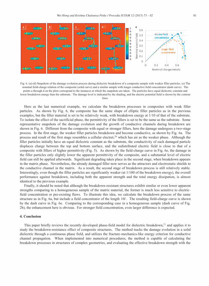
Fig. 6. (a)-(d) Snapshots of the damage evolution process during dielectric breakdown of a composite sample with weaker filler particles. (e) The nominal field-charge relation of the composite (solid curve) and a similar sample with longer conductive field concentrator (dash curve). The points a through d on the plots correspond to the instances at which the snapshots are taken. The particles have equal dielectric constant and
lower breakdown energy than the substrate. The damage level is indicated by the shading, and the electric potential field is shown by the contour lines.
Here as the last numerical example, we calculate the breakdown processes in composites with weak filler particles. As shown by Fig. 6, the composite has the same shape of elliptic filler particles as in the previous examples, but the filler material is set to be relatively weak, with breakdown energy at 1/10 of that of the substrate. To isolate the effect of the sacrificial phase, the permittivity of the fillers is set to be the same as the substrate. Some representative snapshots of the damage evolution and the growth of conductive channels during breakdown are shown in Fig. 6. Different from the composite with equal or stronger fillers, here the damage undergoes a two-stage process. In the first stage, the weaker filler particles breakdown and become conductive, as shown by Fig. 6a. The process and result of the first stage resembles a cellular electret,26 which has air as the weaker phase. Although the filler particles initially have an equal dielectric constant as the substrate, the conductivity of each damaged particle displaces charge between the top and bottom surface, and the redistributed electric field is close to that of a composite with fillers of higher permittivity (Fig. 5). As shown by the field-charge curve in Fig. 6e, the damage in the filler particles only slightly lower the apparent permittivity of the composite, and a substantial level of electric field can still be applied afterwards. Significant degrading takes place in the second stage, when breakdown appears in the matrix phase. Nevertheless, the already damaged filler now serves as the attractors and electrostatic shields to the conductive channel in the matrix. As a result, the second stage of breakdown process is still relatively stable. Interestingly, even though the filler particles are significantly weaker (at 1/100 of the breakdown energy), the overall performance against breakdown, including both the apparent strength and the total energy dissipation, is almost identical to the previous example.
Finally, it should be noted that although the breakdown-resistant structures exhibit similar or even lower apparent strengths comparing to a homogeneous sample of the matrix material, the former is much less sensitive to electric-field concentration or pre-existing flaws. To illustrate this idea, we calculate the breakdown process of the same structure as in Fig. 6a, but include a field concentrator of the length l10 . The resulting field-charge curve is shown by the dash curve in Fig. 6e. Comparing to the corresponding case in a homogeneous sample (dash curve of Fig. 2b), the enhancement here is obvious. For stronger field concentration, even larger difference is expected.
4. Conclusion
This paper briefly reviews the recently developed phase-field model for dielectric breakdown,21 and applies it to study the breakdown-resistance effect of composite structures. The method tracks the damage evolution in a solid dielectric through a continuous phase field, and utilizes the fracture-mechanics-like energy criterion for conductive channel propagation. When implemented into numerical procedures, the method is capable of calculating the breakdown processes in structures of complex geometries, and evaluating the effective breakdown strength with the
a b c d e

82 Wei Hong and Krishna Chaitanya Pitike / Procedia IUTAM 12 ( 2015 ) 73 – 82
presence of electric-field concentration and pre-existing defects. Using this method, various types of composite structures are studied in this paper by varying the permittivity, shape, orientation, and breakdown strength of the filler particles. Results of numerical simulations show that round-shaped filler particles are ineffective in breakdown resistance: round-shaped filler particles of higher dielectric constants tend to introduce electric field concentration, while the stronger particles tend to be circumvented by the one-dimensional conductive channels. The filler particles become more effective in resting conductive channels when they have elliptic shape with the shorter axis aligned in the field direction. In the extreme case when the composite takes the form of a laminate structure, the alternative layers of higher dielectric constants could most effectively shield field concentration, and the composite will be flaw insensitive. Finally, an interesting idea of strengthening a dielectric with weaker filler particles is demonstrated.
Acknowledgements
WH acknowledges the support from NSF through CMMI-1027873.
References
1. Devine RAB. The Physics and Technology of Amorphous SiO2. New York: Plenum Press; 1988. 2. Bradwell A. Electrical Insulation. London: Peter Peregrinus; 1983. 3. Basic research needs for materials under extreme environments. U.S. Department of Energy, Office of Science. 2007. p. 55. 4. Whitehead S. Dielectric Breakdown of Solids. Oxford: Clarendon Press; 1953. 5. O’Dwyer JJ. The Theory of Electrical Conduction and Breakdown in Solid Dielectrics. Oxford: Clarendon Press; 1973. 6. Lombardo S, Crupi F, La Magna A, Spinella C, Terrasi A, La Mantia A, Neri B. Electrical and thermal transient during dielectric breakdown
of thin oxides in metal-SiO2-silicon capacitors. J. Appl. Phys 1998; 84:472. 7. Lombardo S, Stathis JH, Linder BP, Pey KL, Palumbo F, Tung CH. Dielectric breakdown mechanisms in gate oxides. J Appl Phys 2005;
98:121301. 8. Freiman SW, Pohanka RC. Review of mechanically related failures of ceramic capacitors and capacitor materials. J Am Ceram Soc 1989;
72:2258-2263. 9. Bartnikas R. Chapter 3, High Voltage Measurements, In: Bartnikas R ed. Electrical Properties of Solid Insulating Materials: Measurement
Techniques. ASTM STP 926. Philadelphia: ASTM; 1987. pp.157-220. 10. Garboczi EJ. Linear dielectric-breakdown electrostatics. Phys Rev B 1988; 38:9005. 11. Suo Z. Models for breakdown-resistant dielectric and ferroelectric ceramics. J Mech Phys Solids 1993; 41:1155-1176. 12. Elices M, Guinea GV, Gomez J, Planas J. The cohesive zone model: advantages, limitations and challenges. Eng Fracture Mech 2002;
69:137-163. 13. Sukumar N, Moës N, Moran B, Belytschko T. Extended finite element method for three dimensional crack modelling. Int J Numer Methods
Eng 2000; 48:1549-1570. 14. Karma A, Kessler DA, and Levine H. Phase-field model of mode III dynamic fracture. Phys Rev Lett 2001; 87:045501. 15. Eastgate LO, Sethna JP, Rauscher M, Cretegny T, Chen CS, Myers CR. Fracture in mode I using a conserved phase-field model. Phys Rev E
2002; 65:036117. 16. Hakim V, Karma A. Laws of crack motion and phase-field models of fracture. J Mech Phys Solids 2009; 57:342-368. 17. Miehe C, Welschinger F, Hofacker M. Thermodynamically consistent phase field models of fracture: Variational principles and multi-field
FE implementations. Int J Numer Methods Eng 2010; 83:1273-1311. 18. Kuhn C, Müller R. A continuum phase field model for fracture. Eng Fracture Mech 2010; 77:3625-3634. 19. Kuhn C, Müller R. On an energetic interpretation of a phase field model for fracture. Proc Appl Math Mech 2011; 11:159-160. 20. Borden MJ, Verhoosel CV, Scott MA, Hughes TJR, Landis CM. A phase-field description of dynamic brittle fracture. Comp Methods Appl
Mech Eng 2012; 217:77-95. 21. Pitike KC, Hong W. Phase-field model for dielectric breakdown in solids. J Appl Phys 2014; 115:044101. 22. Bao G, Suo Z. Remarks on crack-bridging concepts. Appl Mech Rev 1992; 45:355-366. 23. Evans AG, Zok FW. The physics and mechanics of brittle matrix composites. Solid State Phys 1994; 47:177-286. 24. Gallone G, Carpi F, De Rossi D, Levita G, Marchetti A. Dielectric constant enhancement in a silicone elastomer filled with lead magnesium
niobate-lead titanate. Mater Sci Eng C 2007; 27:110-116. 25. Molberg M, Crespy D, Rupper P, Nüesch F, Månson JAE, Löwe C, Opris DM. High breakdown field dielectric elastomer actuators using
encapsulated polyaniline as high dielectric constant filler. Adv Func Mater 2010; 20:3280-3291. 26. Paajanen M, Lekkala J, Kirjavainen K. ElectroMechanical Film (EMFi) – a new multipurpose electret material. Sensor Actuator A 2000;
84:95.