Modeling and Simulation of Particle Motion in the ...
15
sustainability Article Modeling and Simulation of Particle Motion in the Operation Area of a Centrifugal Rotary Chopper Machine Andrzej Marczuk 1 , Jacek Caban 1, *, Alexey V. Aleshkin 2 , Petr A. Savinykh 2 , Alexey Y. Isupov 2 and Ilya I. Ivanov 3 1 Department of Agricultural, Forestry and Transport Machines, University of Life Sciences in Lublin, 20-612 Lublin, Poland 2 N.V. Rudnitsky North-East Agricultural Research Institute, Kirov 610007, Russia 3 FSBEI HE Vologda State Dairy Farming Academy (DSFA) named after N.V. Vereshchagin, Vologda—Molochnoye 160555, Russia * Correspondence: [email protected]; Tel.: +48-81-531-9612 Received: 11 August 2019; Accepted: 30 August 2019; Published: 6 September 2019 Abstract: The article presents approaches to the formation of a general computational scheme for modeling (simulating) the particle motion on an axisymmetric rotating curved surface with a vertical axis of rotation. To describe the complex particle motion over a given surface, the fundamental equation of particle dynamics in a non-inertial reference frame was used, and by projecting it onto the axes of cylindrical coordinates, the Lagrange’s differential equations of the first kind were obtained. According to the proposed algorithm in C#, an application was developed that enables graphical and numerical control of the calculation results. The program interface contains six screen forms with tabular baseline data (input) and a table of a step-by-step calculation of results (output); particle displacement, velocity, and acceleration diagrams constructed along the axes of the system of cylindrical coordinates ρ and z; graphical presentation of the generate of the surface of revolution and the trajectory of the absolute motion of a particle over the axisymmetric rotating surface developed in polar coordinates. Examples of the calculation of the particle motion are presented. The obtained results can be used for the study and design of machines, for example, centrifugal rotary chopper machines. Keywords: accelerator; axisymmetric surface; general equation of dynamics; non-inertial reference frame 1. Introduction The manufacturing sector has one of the largest impacts on worldwide energy use and natural resource consumption. Traditionally, research on manufacturing processes was mainly conducted to improve efficiency and accuracy and to lower costs [1]. One of the modern challenges in the field of designing manufacturing systems is to determine the optimal level of their flexibility from the point of view of the production tasks being performed. Whether or not a production process to be executed is capable of achieving the assumed performance parameters depends, among others, on the reliability of the machines and technological devices that make up the system under design [2]. As commonly known, the oldest manufacturing techniques used by humans are the grinding, chopper, and milling processes. Research on grinding tries to enhance economic and ecological properties and performance to extend grinding applications in the overall process chain—on the one hand, in the direction of increased material removal rates, avoiding turning and milling, and on the other hand, in the direction of fine finishing, thus making further abrasive finishing processes, such as lapping and polishing, obsolete [3]. Sustainability 2019, 11, 4873; doi:10.3390/su11184873 www.mdpi.com/journal/sustainability
Transcript of Modeling and Simulation of Particle Motion in the ...

sustainability
Article
Modeling and Simulation of Particle Motion in theOperation Area of a Centrifugal RotaryChopper Machine
Andrzej Marczuk 1, Jacek Caban 1,*, Alexey V. Aleshkin 2, Petr A. Savinykh 2, Alexey Y. Isupov 2
and Ilya I. Ivanov 3
1 Department of Agricultural, Forestry and Transport Machines, University of Life Sciences in Lublin,20-612 Lublin, Poland
2 N.V. Rudnitsky North-East Agricultural Research Institute, Kirov 610007, Russia3 FSBEI HE Vologda State Dairy Farming Academy (DSFA) named after N.V. Vereshchagin,
Vologda—Molochnoye 160555, Russia* Correspondence: [email protected]; Tel.: +48-81-531-9612
Received: 11 August 2019; Accepted: 30 August 2019; Published: 6 September 2019�����������������
Abstract: The article presents approaches to the formation of a general computational scheme formodeling (simulating) the particle motion on an axisymmetric rotating curved surface with a verticalaxis of rotation. To describe the complex particle motion over a given surface, the fundamentalequation of particle dynamics in a non-inertial reference frame was used, and by projecting itonto the axes of cylindrical coordinates, the Lagrange’s differential equations of the first kind wereobtained. According to the proposed algorithm in C#, an application was developed that enablesgraphical and numerical control of the calculation results. The program interface contains sixscreen forms with tabular baseline data (input) and a table of a step-by-step calculation of results(output); particle displacement, velocity, and acceleration diagrams constructed along the axes of thesystem of cylindrical coordinates ρ and z; graphical presentation of the generate of the surface ofrevolution and the trajectory of the absolute motion of a particle over the axisymmetric rotating surfacedeveloped in polar coordinates. Examples of the calculation of the particle motion are presented.The obtained results can be used for the study and design of machines, for example, centrifugal rotarychopper machines.
Keywords: accelerator; axisymmetric surface; general equation of dynamics; non-inertial reference frame
1. Introduction
The manufacturing sector has one of the largest impacts on worldwide energy use and naturalresource consumption. Traditionally, research on manufacturing processes was mainly conducted toimprove efficiency and accuracy and to lower costs [1]. One of the modern challenges in the fieldof designing manufacturing systems is to determine the optimal level of their flexibility from thepoint of view of the production tasks being performed. Whether or not a production process tobe executed is capable of achieving the assumed performance parameters depends, among others,on the reliability of the machines and technological devices that make up the system under design [2].As commonly known, the oldest manufacturing techniques used by humans are the grinding, chopper,and milling processes. Research on grinding tries to enhance economic and ecological properties andperformance to extend grinding applications in the overall process chain—on the one hand, in thedirection of increased material removal rates, avoiding turning and milling, and on the other hand,in the direction of fine finishing, thus making further abrasive finishing processes, such as lapping andpolishing, obsolete [3].
Sustainability 2019, 11, 4873; doi:10.3390/su11184873 www.mdpi.com/journal/sustainability

Sustainability 2019, 11, 4873 2 of 15
Many factors influence the sustainability of a manufacturing process, and a combination ofqualitative and quantitative methods are needed to discover them [4]. To resolve these issues, namely,the identification of the type of underlying impact factors, the uncertainty of the influencing factors,and the incompleteness of the evaluation information, the researchers used the evaluation method withanalytical hierarchy process [5,6] and simulations [2,7–9] in the manufacturing sector. Sustainabilityencompasses the three pillars of economic, environmental, and social sustainability [10–12]. In theinvestigation of Ahmad [10], generally, there were approximately 44% (25/57) of highly applicableindicators. Among them, there were 28% (7/25) environmental, 28% (7/25) economic, and 44% (11/25)social indicators [10]. We can, therefore, see that economic and environmental factors are treated onan equal level. Social indicators in sustainable development are highly rated. Nevertheless, in thecase of the two previous ones, they are more adequate for production processes, which have a moreindirect nature on social impact. Beekaroo et al. [13] revealed an index with nine environmental, foureconomic, and two social indicators which were pertinent in sustainability measurement.
One of the most commonly used methods focusing on environmental sustainability is the productlife cycle assessment (LCA). This method is used in many sectors of the economy [14–16] such as energysector [17–19], transport sector [18,19], and food and agricultural industry [20,21]. The limitation ofusing this method is the need for specific and very detailed databases covering a lot of quantitative data.
Another method uses sustainability indicators (SI). In this method, the indicator can be defined “asa measure or aggregation of measures from which one can infer about the phenomenon of interest” [11].This method can capture all three dimensions of sustainable development and help with the evaluationon many levels (e.g., enterprises, objects, processes, and products). In particular, for perpetratorswith limited means and resources, SI provide a good method of analyzing sustainable development.Enterprises can assess their real situation using indicators, raise awareness, and set targets. The resultsof a literature review show that energy costs and GHG (Greenhouse Gas) indicators [10,11,13,19,22–25]are becoming the most commonly used indicators in sustainable planning. On this basis [11,26], fourmain directions of future research on sustainability indicators can also be mentioned: implementationof new optimization methods; adding further sustainable development indicators; extension of themodel on a larger scale of the production system; and loosening certain assumptions. Finding optimalindicators in production processes is not an easy task; generally, we focus on minimizing energyconsumption, waste production, improving the efficiency of machinery and equipment, as well asproduction and logistic processes in a given company. Sustainability indicators are based on measuredand/or estimated data that have to be normalized, scaled, and aggregated consistently [27].
The evolution of design criteria for grinding and chopper machines is driven by functionalrequirements, general trends in machine tools, and cost [28]. The primary functional requirements,as named by Möhring et al. [29], are similar for all machine tools: high static and dynamicstiffness, fatigue strength, damping, thermal and long-term stability, and low weight of movingparts. The grinding and chopper process is carried out in many areas of food manufacturing [30–32]and agriculture [33–35], as well as in the industrial sector [36–38]. The mixing process is highlycomplicated, with a number of affecting parameters, such as the particle properties, the structureand performance of the mixer, the mixing process parameters, and the particle feeding order [38].The crushing method and the machinery used for this purpose should be adapted to the type ofmaterial being ground and, in particular, to its mechanical properties [33,39].
Laboratories and modern industry require fast and effective grinding in small volumes [40]. In thefield of agricultural mechanization, centrifugal chopper machines with a horizontal rotor have recentlyattracted increasing interest. Their principle of action lies in the acceleration of grains due to centrifugalinertia forces with their subsequent grinding (fragmentation) by impact or cutting [41,42]. This is due tothe lower energy consumption for the grinding process in comparison with other choppers (crushers),which, in addition to the direct costs of grain destruction, have the energy costs for drifting wholeand crushed grain using air. In centrifugal rotary chopper machines, the material can be supplied tocrusher/shredder hammers or to a cutting pair by centrifugal inertia forces created by a horizontally

Sustainability 2019, 11, 4873 3 of 15
rotating rotor with working elements. In this, one of the key roles of a centrifugal rotary materialgrinding machine is the distribution bowl or accelerator, which functions to provide a uniform andstable supply of material to the chopper bodies and impart to the material (particles) located on itssurface the necessary linear velocity and trajectory of motion. Despite the rotary blenders relying uponthe action of gravity to cause the powder to cascade and mix within a rotating vessel, the convectiveblenders employ a paddle, impeller, blade, or screw which stirs the powder inside a static vessel [43].
Most of the centrifugal rotary grinding machines in their design have a central feed of the materialinto the accelerator made in the form of a flat disc. However, with this material feed, the acceleration ofa particle that is closest to the axis of rotation will be difficult because of the lack of initial velocity andcentrifugal forces to overcome the friction forces, which provokes the appearance of a stagnant zoneand an increase in the cost of overcoming them. To solve this problem, two approaches can be used:feeding the material with an offset from the axis of rotation, leading to design complexity, or usingthe reflective surface of the splitter, which is a straight conical surface located coaxially with the axisof rotation, ensuring the separation of the particles to be ground from the axis of rotation and givingthem the initial velocity. In centrifugal impact grinders using the “stone-crushing-stone” principlewith self-lining, the trajectory of the particles to be ground (milled) is equally important.
Figure 1 shows the rotary chopper machine analyzed in this study.
Sustainability 2019, 11, x FOR PEER REVIEW 3 of 15
for drifting whole and crushed grain using air. In centrifugal rotary chopper machines, the material can be supplied to crusher/shredder hammers or to a cutting pair by centrifugal inertia forces created by a horizontally rotating rotor with working elements. In this, one of the key roles of a centrifugal rotary material grinding machine is the distribution bowl or accelerator, which functions to provide a uniform and stable supply of material to the chopper bodies and impart to the material (particles) located on its surface the necessary linear velocity and trajectory of motion. Despite the rotary blenders relying upon the action of gravity to cause the powder to cascade and mix within a rotating vessel, the convective blenders employ a paddle, impeller, blade, or screw which stirs the powder inside a static vessel [43].
Most of the centrifugal rotary grinding machines in their design have a central feed of the material into the accelerator made in the form of a flat disc. However, with this material feed, the acceleration of a particle that is closest to the axis of rotation will be difficult because of the lack of initial velocity and centrifugal forces to overcome the friction forces, which provokes the appearance of a stagnant zone and an increase in the cost of overcoming them. To solve this problem, two approaches can be used: feeding the material with an offset from the axis of rotation, leading to design complexity, or using the reflective surface of the splitter, which is a straight conical surface located coaxially with the axis of rotation, ensuring the separation of the particles to be ground from the axis of rotation and giving them the initial velocity. In centrifugal impact grinders using the “stone-crushing-stone” principle with self-lining, the trajectory of the particles to be ground (milled) is equally important.
Figure 1 shows the rotary chopper machine analyzed in this study.
Figure 1. Tornado chopper machine: 1—feed-in tube; 2—case cover; 3—accelerator; 4—accelerating blade; 5—shredding element; 6—electric motor; 7—V-belt drive.
Figure 2 shows a scheme of self-lining formation in the accelerator.
Figure 1. Tornado chopper machine: 1—feed-in tube; 2—case cover; 3—accelerator; 4—acceleratingblade; 5—shredding element; 6—electric motor; 7—V-belt drive.
Figure 2 shows a scheme of self-lining formation in the accelerator.
Sustainability 2019, 11, x FOR PEER REVIEW 3 of 15
for drifting whole and crushed grain using air. In centrifugal rotary chopper machines, the material can be supplied to crusher/shredder hammers or to a cutting pair by centrifugal inertia forces created by a horizontally rotating rotor with working elements. In this, one of the key roles of a centrifugal rotary material grinding machine is the distribution bowl or accelerator, which functions to provide a uniform and stable supply of material to the chopper bodies and impart to the material (particles) located on its surface the necessary linear velocity and trajectory of motion. Despite the rotary blenders relying upon the action of gravity to cause the powder to cascade and mix within a rotating vessel, the convective blenders employ a paddle, impeller, blade, or screw which stirs the powder inside a static vessel [43].
Most of the centrifugal rotary grinding machines in their design have a central feed of the material into the accelerator made in the form of a flat disc. However, with this material feed, the acceleration of a particle that is closest to the axis of rotation will be difficult because of the lack of initial velocity and centrifugal forces to overcome the friction forces, which provokes the appearance of a stagnant zone and an increase in the cost of overcoming them. To solve this problem, two approaches can be used: feeding the material with an offset from the axis of rotation, leading to design complexity, or using the reflective surface of the splitter, which is a straight conical surface located coaxially with the axis of rotation, ensuring the separation of the particles to be ground from the axis of rotation and giving them the initial velocity. In centrifugal impact grinders using the “stone-crushing-stone” principle with self-lining, the trajectory of the particles to be ground (milled) is equally important.
Figure 1 shows the rotary chopper machine analyzed in this study.
Figure 1. Tornado chopper machine: 1—feed-in tube; 2—case cover; 3—accelerator; 4—accelerating blade; 5—shredding element; 6—electric motor; 7—V-belt drive.
Figure 2 shows a scheme of self-lining formation in the accelerator.
Figure 2. Scheme of self-lining formation in the accelerator: 1—a splitter; 2—wear plate; 3—self-liningpocket; 4—carbide blade; 5—descent of the material from the accelerator; 6—accelerator case.
Sustainability 2019, 11, 4873 4 of 15
The main contribution of this study is the modeling (simulating) of the particle motion onan axisymmetric rotating curved surface with a vertical axis of rotation, whose calculation can beused for the study and design of machines, for example, centrifugal rotary chopper machines. Amathematical model of motion was developed on the basis of step-by-step numerical integration ofthe obtained closed system of differential equations with an equation of constraint describing thesurface of revolution. An application based on the algorithm in C# under MS Visual Studio (Microsoft,Redmond, Washington, USA) was developed that enables graphical and numerical control of thecalculation results. Moreover, the results of the calculations of the particle motion trajectory andkinematic indicators are presented. The conducted simulation tests show possibilities of improvingthe process efficiency and shortening the operation times, which results in economic benefits duringsustainable manufacturing.
2. Materials and Methods
Hypothesis. One of the methods to achieve this goal takes into account the form of the accelerator,allowing us to set the initial kinematic parameters and particle trajectory, which in turn will affectthe geometric dimensions, metal consumption, and technological modes of operation of a centrifugalrotary chopper or its nodes, for example, rotor (crusher) speed and material feed rate, which wouldthen reduce the specific energy consumption per unit of output.
Methods. To solve this problem, we modeled the motion of a particle of the material on a rotatingcurved surface. To do this, we used the basic law of particle dynamics (dynamics of a material point)and considered the motion of a particle on the surface of an axisymmetric spinning bowl. We usedstep-by-step numerical integration, which allowed us to obtain data for analyzing the particle.
3. Results and Discussion
3.1. Modeling Results
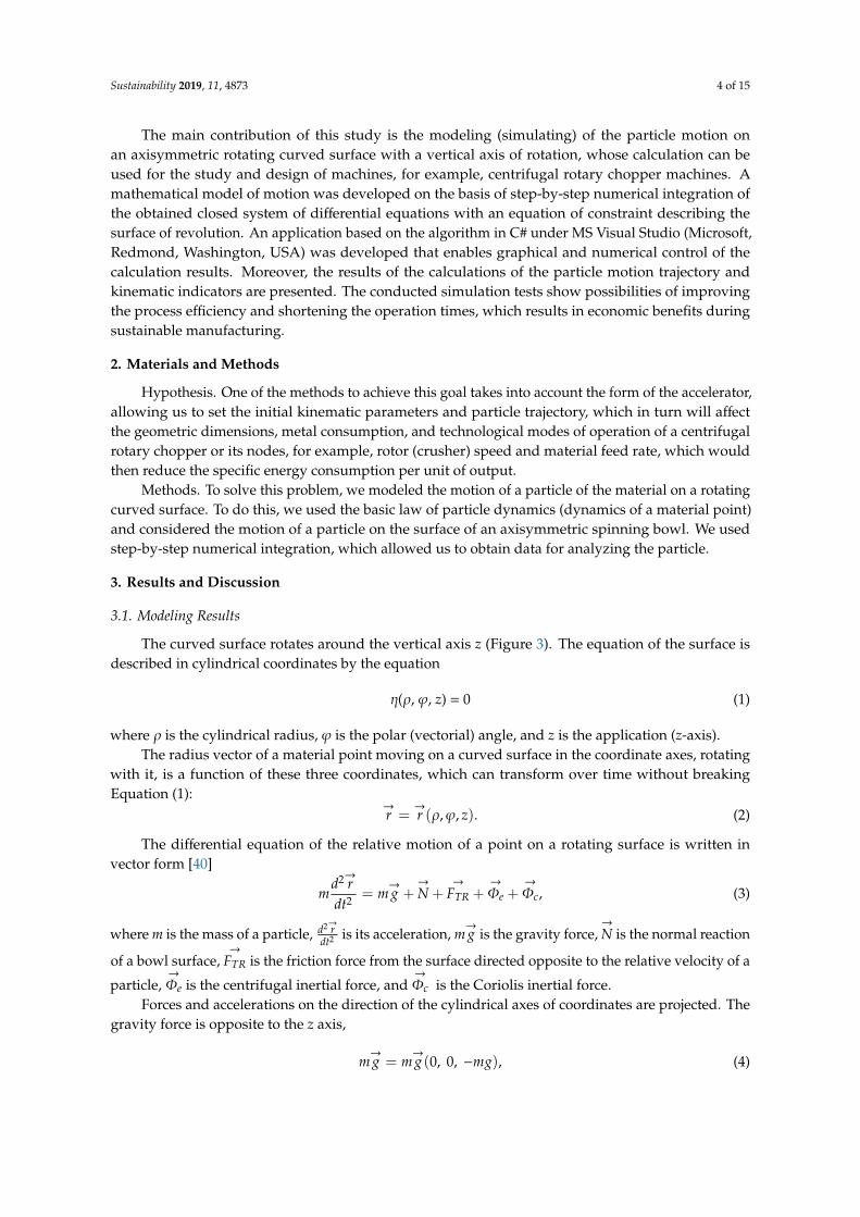
The curved surface rotates around the vertical axis z (Figure 3). The equation of the surface isdescribed in cylindrical coordinates by the equation
η(ρ, ϕ, z) = 0 (1)
where ρ is the cylindrical radius, ϕ is the polar (vectorial) angle, and z is the application (z-axis).The radius vector of a material point moving on a curved surface in the coordinate axes, rotating
with it, is a function of these three coordinates, which can transform over time without breakingEquation (1):
→r =
→r (ρ,ϕ, z). (2)
The differential equation of the relative motion of a point on a rotating surface is written invector form [40]
md2→rdt2 = m
→g +
→
N +→
FTR +→
Φe +→
Φc, (3)
where m is the mass of a particle, d2→rdt2 is its acceleration, m
→g is the gravity force,
→
N is the normal reaction
of a bowl surface,→
FTR is the friction force from the surface directed opposite to the relative velocity of a
particle,→
Φe is the centrifugal inertial force, and→
Φc is the Coriolis inertial force.Forces and accelerations on the direction of the cylindrical axes of coordinates are projected. The
gravity force is opposite to the z axis,
m→g = m
→g (0, 0, −mg), (4)

Sustainability 2019, 11, 4873 5 of 15
where→g is free-fall acceleration. The normal reaction of a rotating curved surface is
→
N = λ·grad( η), (5)
where λ = λ(t) is Lagrange’s indeterminate multiplier [44], grad(η) is the vector gradient to the equationof surface (1), which has projections on the axial cylindrical coordinate system with the ϕ axis directedperpendicular to the ρ, z, axes and passing through the moving point, so that the axes ρ, ϕ, z form theright-hand system of vectors:
(grad(η))ρ =∂η∂ρ
(grad(η))ϕ =∂η∂ϕ
(grad(η))z =∂η∂z
·1ρ
. (6)
Sustainability 2019, 11, x FOR PEER REVIEW 5 of 15
Figure 3. Design diagram of the motion of a particle on a rotating curved surface.
The radius vector of a material point moving on a curved surface in the coordinate axes, rotating with it, is a function of these three coordinates, which can transform over time without breaking Equation (1): 𝑟 = 𝑟(𝜌, 𝜑, 𝑧). (2)
The differential equation of the relative motion of a point on a rotating surface is written in vector form [40] 𝑚 = 𝑚�� + 𝑁 + 𝐹 + 𝛷 + 𝛷, (3)
where m is the mass of a particle, is its acceleration, 𝑚�� is the gravity force, 𝑁 is the normal reaction of a bowl surface, 𝐹 is the friction force from the surface directed opposite to the relative velocity of a particle, 𝛷 is the centrifugal inertial force, and 𝛷 is the Coriolis inertial force.
Forces and accelerations on the direction of the cylindrical axes of coordinates are projected. The gravity force is opposite to the z axis, 𝑚�� = 𝑚��(0, 0, −𝑚𝑔), (4)
where �� is free-fall acceleration. The normal reaction of a rotating curved surface is 𝑁 = 𝜆 ∙ 𝑔𝑟𝑎𝑑( 𝜂), (5)
where λ = λ(t) is Lagrange’s indeterminate multiplier [44], grad(η) is the vector gradient to the equation of surface (1), which has projections on the axial cylindrical coordinate system with the φ axis directed perpendicular to the ρ, z, axes and passing through the moving point, so that the axes ρ, φ, z form the right-hand system of vectors:
⎩⎪⎨⎪⎧(𝑔𝑟𝑎𝑑( 𝜂)) =(𝑔𝑟𝑎𝑑( 𝜂)) =(𝑔𝑟𝑎𝑑( 𝜂)) = ∙ . (6)
The projections of the normal reaction 𝑁 are:
Figure 3. Design diagram of the motion of a particle on a rotating curved surface.
The projections of the normal reaction→
N are:Nρ = λ
∂η∂ρ
Nϕ = λ∂η∂ϕ
Nz = λ∂η∂z
·1ρ
. (7)
The modulus of the normal reaction is found by
N =
∣∣∣∣∣→N∣∣∣∣∣ = |λ|√(
∂η
∂ρ
)2
+
(∂η
∂ϕ1ρ
)2
+
(∂η
∂z
)2
. (8)
At a constant angular velocity of rotation (spin rate) of the curved surface→ω, the centrifugal
inertial force→
Φe is directed along the radius ρ in accordance with the result of vector products inits definition
→
Φe = −m→ω ×
(→ω ×
→r), (9)

Sustainability 2019, 11, 4873 6 of 15
where→r is determined by Equation (2), then
Φeρ = mω2ρΦeϕ = 0Φez = 0
. (10)
Coriolis inertial force→
Φc is by definition equal to
→
Φc = −2m→ω ×
→v , (11)
where→v is the relative velocity of a material point in the moving axes of coordinates, and the modulus
of relative velocity is associated with the cylindrical coordinates by
v =
√.ρ
2+
(ρ
.ϕ)2+
.z2. (12)
Then, the projections of the Coriolis force equalΦcρ = 2mω
.ϕρ
Φcϕ = −2m.ρω
Φcz = 0. (13)
The friction force of a particle on the bowl surface→
FTR is determined by Coulomb’s law through anormal reaction and it is opposite in direction to the relative velocity:
→
FTR = −
∣∣∣∣∣→N∣∣∣∣∣ f →vv (14)
FTRρ = −
∣∣∣∣∣→N∣∣∣∣∣ f .ρv
FTRϕ = −
∣∣∣∣∣→N∣∣∣∣∣ f .ϕρv
FTRz = −
∣∣∣∣∣→N∣∣∣∣∣ f .zv
. (15)
Let us project Equation (3) on the axis of the moving system of cylindrical coordinates rotatingtogether with the curved surface by using the found projections of all forces:
m( ..ρ− ρ
.ϕ
2)= λ
∂η∂ρ −N f
.ρv + mω2ρ+ 2mω
.ϕρ
m 1ρ
ddt
(ρ2 .ϕ)= −N f
.ϕρv − 2m
.ρω
m..z = −mg + λ
∂η∂z −N f
.zv
. (16)
Let us transform the second equation of the system, taking into account the projection ofacceleration on the ϕ axis:
1ρ
ddt
(ρ2 .ϕ)= 2
.ρ
.ϕ+ ρ
..ϕ. (17)
By bringing all forces to a unit mass of a particle m = 1, we obtain..ρ = ρ
.ϕ
2+ λ
∂η∂ρ −N f
.ρv +ω2ρ+ 2ω
.ϕρ
..ϕ = 1
ρ
(−2
.ρ
.ϕ−N f
.ϕρv − 2
.ρω
)..z = −g + λ
∂η∂z −N f
.zv
. (18)

Sustainability 2019, 11, 4873 7 of 15
To obtain a closed system of equations, we supplement the system (18) with a coupling equation(of constraints) (1) (see Supplementary Material). Then, four unknown functions ρ(t), ϕ(t), z(t), λ(t) canbe found by solving a system of three differential (18) and one algebraic (1) equations.
In the equation, various forms of execution of the surface of revolution are possible (1). Let usdefine the coupling equation in the form of an axisymmetric surface described by a power functionpassing through the given starting and final points of motion, written as
zzK
= a0 +
(ρ
ρK
)n
, (19)
where a0 is a summand determined from the condition of belonging to a given surface of revolution ofthe initial point of the trajectory with the coordinates
ρ(0) = ρ0, ϕ(0) = 0, z(0) = 0 (20)
ρK, zK are coordinates of the final point of the trajectory, where the surface described by Equation (19)ends for all values of the polar (vectorial) angle ϕ; n is an exponent in the equation of surface, whichchanges the degree of the bowl concavity and which can be varied to achieve the required parametersof the particle motion.
Thus, the origin of coordinates of the moving frame of reference, in which the particle motionis described, always corresponds along the z axis to the starting point of the motion trajectory, andthe parabola vertex in the axial section of the surface of revolution lies on this axis below zero bythe value a0:
a0 = −
(ρ0
ρK
)n
. (21)
Let us reduce Equation (19) to the form (1)
η(ρ,ϕ, z) =z
zK− a0 −
(ρ
ρK
)n
= 0, (22)
and calculate the partial derivatives in the gradient expression to the constraint surface∂η∂ρ = −n
( ρρK
)n−1 1ρK
∂η∂ϕ = 0∂η∂z = 1
zK
. (23)
These expressions in Equation (23) should be substituted in the projection of force→
N , a normalreaction to the constraint surface in Equation (18).
From the last equation of the system (18) we find the Lagrange multiplier
λ =1(∂η∂z
) (..z + g + N f
.zv
). (24)
Since, when moving along the surface, only two cylindrical coordinates are independent, then forstep-by-step numerical integration, we take the first two differential Equations (18) as the basis andcalculate the coordinate z and its time derivatives through coupling Equation (22):
z = zKa0 + zK
(ρ
ρK
)n
(25)

Sustainability 2019, 11, 4873 8 of 15
.z = nzK
1ρK
(ρ
ρK
)n−1.ρ (26)
..z = nzK
1ρK
(n− 1)(ρ
ρK
)n−2 .ρ
2
ρK+ nzK
1ρK
(ρ
ρK
)n−1..ρ. (27)
In Equations (24)–(27), the coordinate values ρ and ϕ, as well as their time derivatives.ρ,
.ϕ at
the next integration step, are assumed to be equal to their value at the end of the previous integrationstep. The procedure of numerical integration of the system of Equation (18) was carried out by themethod of averaged acceleration [45], using the original algorithmic program for “Windows” coded inC# under MS Visual Studio.
3.2. Results and Discussion
The results of the analysis of the kinematic parameters of the motion and trajectory of the particle,which initiate motion, with no initial linear velocity v0 and with an angular velocity ω0 equal inmagnitude to the angular velocity of rotation ωe, for different curvilinear surfaces (Figure 4) of theaccelerator, are presented in Figure 5. It shows that the use of a concave curvilinear surface (na = 2)allowed to double the value of the acquired velocity vabs in comparison with the flat surface (na = 0)and to increase it 1.7 times compared to a conical surface (na = −0.1) at a descent from a rotating surface,which is a consequence of the time spent by the particle on the surface, for example, when na = 2,the time was t = 2.05 s, when na = 0, the time was t = 0.84 s, and when na = −0.1, the time was t = 0.38 s.When the shape of the rotating surface changed from concave na = 2 to convex na = −0.1, the totallength of the path traveled by the particle—that is, its trajectory—decreased.
Sustainability 2019, 11, x FOR PEER REVIEW 8 of 15
𝑧 = 𝑛𝑧 (𝑛 − 1) + 𝑛𝑧 𝜌. (27)
In equations (24)–(27), the coordinate values ρ and φ, as well as their time derivatives 𝜌, 𝜑 at the next integration step, are assumed to be equal to their value at the end of the previous integration step. The procedure of numerical integration of the system of equation (18) was carried out by the method of averaged acceleration [45], using the original algorithmic program for “Windows” coded in C# under MS Visual Studio.
3.2. Results and Discussion
The results of the analysis of the kinematic parameters of the motion and trajectory of the particle, which initiate motion, with no initial linear velocity 𝑣 and with an angular velocity 𝜔 equal in magnitude to the angular velocity of rotation 𝜔 , for different curvilinear surfaces (Figure 4) of the accelerator, are presented in Figure 5. It shows that the use of a concave curvilinear surface (na = 2) allowed to double the value of the acquired velocity 𝑣 in comparison with the flat surface (na = 0) and to increase it 1.7 times compared to a conical surface (na = −0.1) at a descent from a rotating surface, which is a consequence of the time spent by the particle on the surface, for example, when na
= 2, the time was t = 2.05 s, when na = 0, the time was t = 0.84 s, and when na = −0.1, the time was t = 0.38 s. When the shape of the rotating surface changed from concave na = 2 to convex na = −0.1, the total length of the path traveled by the particle—that is, its trajectory—decreased.
Figure 4. Variants of generates of the studied curvilinear surfaces of the accelerator. Figure 4. Variants of generates of the studied curvilinear surfaces of the accelerator.

Sustainability 2019, 11, 4873 9 of 15
Sustainability 2019, 11, x FOR PEER REVIEW 9 of 15
(a)
(b)
Figure 5. Cont.

Sustainability 2019, 11, 4873 10 of 15
Sustainability 2019, 11, x FOR PEER REVIEW 10 of 15
(c)
Figure 5. Data for analyzing the velocity and trajectory of the particle motion, which is introduced with no initial linear velocity and with angular velocity equal in magnitude to the angular velocity of rotation for different curvilinear surfaces of the accelerator: (а) na = 2 (concave); (b) na = 0 (straight line); (c) na = −0.1 (conical curvilinear).
The calculations were carried out for different variable characteristics of the surface, initial indicators of kinematic parameters, and friction coefficient. Figure 6a presents an example of tabular data with the results of calculations and diagrams of changes in the motion trajectory, velocity, and acceleration of a particle along the cylindrical axes ρ and z.
Analysis of the diagrams presented in Figure 6b, c made it possible to note that the particle reached its maximum velocity in 0.313 s, being at a distance of ρ = 0.0092 m from the axis of rotation. At the same time, the subsequent changes in velocity, down to its descent from the concave surface, had a damped harmonic nature.
Figure 5. Data for analyzing the velocity and trajectory of the particle motion, which is introducedwith no initial linear velocity and with angular velocity equal in magnitude to the angular velocity ofrotation for different curvilinear surfaces of the accelerator: (a) na = 2 (concave); (b) na = 0 (straightline); (c) na = −0.1 (conical curvilinear).
The calculations were carried out for different variable characteristics of the surface, initialindicators of kinematic parameters, and friction coefficient. Figure 6a presents an example of tabulardata with the results of calculations and diagrams of changes in the motion trajectory, velocity, andacceleration of a particle along the cylindrical axes ρ and z.
Analysis of the diagrams presented in Figure 6b, c made it possible to note that the particle reachedits maximum velocity in 0.313 s, being at a distance of ρ = 0.0092 m from the axis of rotation. At thesame time, the subsequent changes in velocity, down to its descent from the concave surface, had adamped harmonic nature.
Thus, curvilinear surfaces of concave nature combining conical and concave surfaces are of greatinterest for further research. The trajectories of the particles and their kinematic indicators can be usedto determine the relationship between the design factors and the process parameters of centrifugalchoppers, such as the time when the particle is on a dispensing bowl, the descent velocity of the particlefrom the bowl, and the shape of accelerating blades.

Sustainability 2019, 11, 4873 11 of 15
Sustainability 2019, 11, x FOR PEER REVIEW 11 of 15
(a)
(b)
Figure 6. Cont.

Sustainability 2019, 11, 4873 12 of 15
Sustainability 2019, 11, x FOR PEER REVIEW 12 of 15
(c)
Figure 6. Example of the results of calculations of the particle motion trajectory and kinematic indicators for na = 2; (а) tabular data; (b) diagrams of particle displacement, velocity, and acceleration along the axis ρ; (c) diagrams of particle displacement, velocity, and acceleration along the axis z.
Thus, curvilinear surfaces of concave nature combining conical and concave surfaces are of great interest for further research. The trajectories of the particles and their kinematic indicators can be used to determine the relationship between the design factors and the process parameters of centrifugal choppers, such as the time when the particle is on a dispensing bowl, the descent velocity of the particle from the bowl, and the shape of accelerating blades.
The ability to achieve the assumed performance parameters of the production process planned for implementation depends on the degree of reliability of the machines and technological devices included in the designed system [2]. Based on previous research [34], it can be confirmed that with the optimal values of the technological process (efficiency, time of a given operation—mixing or mining, coefficient of friction, and particle movement), it is possible to reduce energy consumption. Data on the possibility of improving the operation of production processes of various enterprises in Germany are presented by Steinhofel and others [46]. As we know, many factors influence the production process, for example, technical, economic, and social factors. Due to the above reasons, obtaining such large benefits in the whole production process, where various technological machines operate (technological operations), is difficult; nevertheless, it enables the introduction of sustainable production processes. The conducted simulation tests show possibilities of improving process efficiency and shortening the operation times, which results in economic benefits. The lower energy consumption and the increase in the efficiency of technological processes will also lead to the generation of less post-production waste (ecological benefits), which is in line with the principles of sustainable development.
4. Conclusions
In this study, a closed system of equations was obtained with a coupling equation (of constraints) that allows modeling a particle motion on a rotating surface; when numerically integrating them, it is possible to evaluate the use of a particular accelerator surface of a centrifugal rotary chopper machine to achieve the desired results in terms of downsizing, increasing productivity, or improving
Figure 6. Example of the results of calculations of the particle motion trajectory and kinematic indicatorsfor na = 2; (a) tabular data; (b) diagrams of particle displacement, velocity, and acceleration along theaxis ρ; (c) diagrams of particle displacement, velocity, and acceleration along the axis z.
The ability to achieve the assumed performance parameters of the production process plannedfor implementation depends on the degree of reliability of the machines and technological devicesincluded in the designed system [2]. Based on previous research [34], it can be confirmed that with theoptimal values of the technological process (efficiency, time of a given operation—mixing or mining,coefficient of friction, and particle movement), it is possible to reduce energy consumption. Data on thepossibility of improving the operation of production processes of various enterprises in Germany arepresented by Steinhofel and others [46]. As we know, many factors influence the production process,for example, technical, economic, and social factors. Due to the above reasons, obtaining such largebenefits in the whole production process, where various technological machines operate (technologicaloperations), is difficult; nevertheless, it enables the introduction of sustainable production processes.The conducted simulation tests show possibilities of improving process efficiency and shortening theoperation times, which results in economic benefits. The lower energy consumption and the increasein the efficiency of technological processes will also lead to the generation of less post-productionwaste (ecological benefits), which is in line with the principles of sustainable development.
4. Conclusions
In this study, a closed system of equations was obtained with a coupling equation (of constraints)that allows modeling a particle motion on a rotating surface; when numerically integrating them,it is possible to evaluate the use of a particular accelerator surface of a centrifugal rotary choppermachine to achieve the desired results in terms of downsizing, increasing productivity, or improvingthe quality of shredding. The use of numerical integration methods allows to consider the influenceof physical and geometrical processes and kinematic parameters on the output result, for example,traveling time and velocity in cylindrical coordinates. Thus, the simulation of the particle motion

Sustainability 2019, 11, 4873 13 of 15
along an accelerator allows choosing rational geometrical dimensions of the chopper machine and itsoptimal operating practice.
Supplementary Materials: The Supplementary Materials are available online at http://www.mdpi.com/2071-1050/11/18/4873/s1.
Author Contributions: Conceptualization, J.C., P.A.S. and I.I.I.; Data curation, A.V.A.; Formal analysis, A.M.,A.V.A., A.Y.I. and I.I.I.; Methodology, A.V.A., P.A.S. and A.Y.I.; Resources, J.C.; Software, P.A.S.; Writing—originaldraft, J.C., P.A.S. and A.Y.I.; Writing—review & editing, J.C. and I.I.I.
Funding: This research received no external funding.
Acknowledgments: We are thankful to the Editor and the reviewers for their valuable comments and detailedsuggestions to improve the paper.
Conflicts of Interest: The authors declare no conflict of interest.
References
1. Linke, B.S.; Corman, G.J.; Dornfeld, D.A.; Tonissen, S. Sustainability indicators for discrete manufacturingprocesses applied to grinding technology. J. Manuf. Syst. 2013, 32, 556–563. [CrossRef]
2. Gola, A. Reliability analysis of reconfigurable manufacturing system structures using computer simulationmethods. Eksploat. I Niezawodn. Maint. Reliab. 2019, 21, 90–102. [CrossRef]
3. Wegener, K.; Bleicher, F.; Krajnik, P.; Hoffmeister, H.W.; Brecher, C. Recent developments in grindingmachines. Cirp Ann. Manuf. Technol. 2017, 66, 779–802. [CrossRef]
4. Zhou, Z.; Dou, Y.; Sun, J.; Jiang, J.; Tan, Y. Sustainable Production Line Evaluation Based on EvidentialReasoning. Sustainability 2017, 9, 1811. [CrossRef]
5. Shankar, K.M.; Kumar, P.U.; Kannan, D. Analyzing the Drivers of Advanced Sustainable ManufacturingSystem Using AHP Approach. Sustainability 2016, 8, 824. [CrossRef]
6. Wu, G.; Duan, K.; Zuo, J.; Zhao, X.; Tang, D. Integrated Sustainability Assessment of Public RentalHousing Community Based on a Hybrid Method of AHP-Entropy Weight and Cloud Model Sustainability.Sustainability 2017, 9, 603.
7. Bardelli, M.; Cravero, C.; Marini, M.; Marsano, D.; Milingi, O. Numerical Investigation of Impeller-VanedDiffuser Interaction in a Centrifugal Compressor. Appl. Sci. 2019, 9, 1619. [CrossRef]
8. Faria, P.M.C.; Rajamain, R.K.; Tavares, L.M. Optimization of Solids Concentration in Iron Ore Ball Millingthrough Modeling and Simulation. Minerals 2019, 9, 366. [CrossRef]
9. Koltai, T.; Lozano, S.; Uzonyi-Kecskés, J.; Moreno, P. Evaluation of the results of a production simulationgame using a dynamic DEA approach. Comput. Ind. Eng. 2017, 105, 1–11. [CrossRef]
10. Ahmad, S.; Wong, K.Y. Development of weighted triple-bottom line sustainability indicators for the Malaysianfood manufacturing industry using the Delphi method. J. Clean. Prod. 2019, 229, 1167–1182. [CrossRef]
11. Joung, C.B.; Carrell, J.; Sarkar, P.; Feng, S.C. Categorization of indicators for sustainable manufacturing.Ecol. Indic. 2013, 24, 148–157. [CrossRef]
12. Krajn, D.; Glavic, P. Indicators of sustainable production. Clean Technol. Environ. Policy 2003, 5, 279–288.[CrossRef]
13. Beekaroo, D.; Callychurn, D.S.; Hurreeram, D.K. Developing a sustainability index for Mauritianmanufacturing companies. Ecol. Indic. 2019, 96, 250–257. [CrossRef]
14. Filleti, R.A.P.; Silva, D.A.L.; da Silva, E.J.; Ometto, A.R. Productive and environmental performance indicatorsanalysis by a combined LCA hybrid model and real-time manufacturing process monitoring: A grindingunit process application. J. Clean. Prod. 2017, 161, 510–523. [CrossRef]
15. Machado, C.G.; Despeisse, M.; Winroth, M.; Ribeiro da Silva, E.H.D. Additive manufacturing from thesustainability perspective: Proposal for a self-assessment tool. In Proceedings of the 52nd CIRP Conferenceon Manufacturing Systems, Procedia CIRP, Ljubljana, Slovenia, 12–14 June 2019; Volume 81, pp. 482–487.
16. Zarte, M.; Pechmann, A.; Nunes, I.L. Decision support systems for sustainable manufacturing surroundingthe product and production life cycle—A literature review. J. Clean. Prod. 2019, 219, 336–349. [CrossRef]
17. Piasecka, I.; Tomporowski, A.; Flizikowski, J.; Kruszelnicka, W.; Kasner, R.; Mrozinski, A. Life Cycle Analysisof Ecological Impacts of an Offshore and a Land-Based Wind Power Plant. Appl. Sci. 2019, 9, 231. [CrossRef]

Sustainability 2019, 11, 4873 14 of 15
18. Wang, R.; Wu, Y.; Ke, W.; Zhang, S.; Zhou, B.; Hao, J. Can propulsion and fuel diversity for the bus fleetachieve the win–win strategy of energy conservation and environmental protection? Appl. Energy 2015,147, 92–103. [CrossRef]
19. Ventura, J.A.; Kweon, S.J.; Hwang, S.W.; Tormay, M.; Li, C. Energy policy considerations in the design of analternative-fuel refueling infrastructure to reduce GHG emissions on a transportation network. Energy Policy2017, 111, 427–439. [CrossRef]
20. Arzoumanidis, I.; Salomone, R.; Petti, L.; Mondello, G.; Raggi, A. Is there a simplified LCA tool suitable forthe agri-food industry? An assessment of selected tools. J. Clean. Prod. 2017, 149, 406–425. [CrossRef]
21. Tassielli, G.; Renzulli, P.A.; Mousavi-Avval, S.H.; Notarnicola, B. Quantifying life cycle inventories ofagricultural field operations by considering different operational parameters. Int. J. Life Cycle Assess. 2019,24, 1075–1092. [CrossRef]
22. Helleno, A.L.; Isaias de Moraes, A.J.; Simon, A.T. Integrating sustainability indicators and Lean Manufacturingto assess manufacturing processes: Application case studies in Brazilian industry. J. Clean. Prod. 2017,153, 405–416. [CrossRef]
23. Skrucany, T.; Ponicky, J.; Kendra, M.; Gnap, J. Comparison of railway and road passenger transport in energyconsumption and GHG production. In Proceedings of the Third International Conference on Traffic andTransport Engineering (ICTTE), Lucerne, Switzerland, 6–10 July 2016; pp. 744–749.
24. Skrucany, T.; Semanova, S.; Figlus, T.; Sarkan, B.; Gnap, J. Energy intensity and GHG production of chosenpropulsions used in road transport. Commun. Sci. Lett. Univ. Zilina 2017, 19, 3–9.
25. Tucki, K.; Mruk, R.; Orynych, O.; Wasiak, A.; Botwinska, K.; Gola, A. Simulation of the Operation of a SparkIgnition Engine Fueled with Various Biofuels and Its Contribution to Technology Management. Sustainability2019, 11, 2799. [CrossRef]
26. Akbar, M.; Irohara, T. Scheduling for sustainable manufacturing: A review. J. Clean. Prod. 2018, 205, 866–883.[CrossRef]
27. Singh, R.K.; Murty, H.R.; Gupta, S.K.; Dikshit, A.K. An overview of sustainability assessment methodologies.Ecol. Indic. 2012, 15, 281–299. [CrossRef]
28. Leonesio, M.; Bianchi, G.; Cau, N. Design criteria for grinding machine dynamic stability. Procedia Cirp 2018,78, 382–387. [CrossRef]
29. Möhring, H.C.; Brecher, C.; Abele, E.; Fleischer, J.; Bleicher, F. Materials in machine tool structures. Cirp Ann.Manuf. Technol. 2015, 64, 725–748. [CrossRef]
30. Madej, O.; Kruszelnicka, W.; Tomporowski, A. Wyznaczanie procesowych charakterystykwielokrawedziowego rozdrabniania ziaren kukurydzy. Inzynieria I Apar. Chem. 2016, 4, 144–145.
31. Stadnyk, I.; Vitenko, T.; Drozdziel, P.; Derkach, A. Simulation of components mixing in order to determinerational parameters of working bodies. Adv. Sci. Technol. Res. J. 2016, 10, 30–138. [CrossRef]
32. Tong, J.; Xu, S.; Chen, D.; Li, M. Design of a Bionic Blade for Vegetable Chopper. J. Bionic Eng. 2017,14, 163–171. [CrossRef]
33. Flizikowski, J.; Topolinski, T.; Opielak, M.; Tomporowski, A.; Mrozinski, A. Research and analysis ofoperating characteristics of energetic biomass micronizer. Eksploat. I Niezawodn. Maintanance Reliab. 2015,17, 19–26. [CrossRef]
34. Marczuk, A.; Misztal, W.; Savinykh, P.; Turubanov, N.; Isupov, A.; Zyryanov, D. Improving efficiency ofhorizontal ribbon mixer by optimizing its constructional and operational parameters. Eksploat. I Niezawodn.–Maint. Reliab. 2019, 21, 220–225. [CrossRef]
35. Rocha, A.G.; Montanhini, R.N.; Dilkin, P.; Tamiosso, C.D.; Mallmann, C.A. Comparison of different indicatorsfor the evaluation of feed mixing efficiency. Anim. Feed Sci. Technol. 2015, 209, 249–256. [CrossRef]
36. Tropp, M.; Tomasikova, M.; Bastovansky, R.; Krzywonos, L.; Brumercik, F. Concept of deep drawingmechatronic system working in extreme conditions. Procedia Eng. 2017, 192, 893–898. [CrossRef]
37. Vitenko, T.; Drozdziel, P.; Rudawska, A. Industrial usage of hydrodynamic cavitation device. Adv. Sci.Technol. Res. J. 2018, 12, 158–167. [CrossRef]
38. Xiao, X.; Tan, Y.; Zhang, H.; Jiang, S.; Wang, J.; Deng, R.; Cao, G.; Wu, B. Numerical investigation on theeffect of the particle feeding order on the degree of mixing using DEM. Procedia Eng. 2015, 102, 1850–1856.[CrossRef]
39. Tomporowski, A.; Flizikowski, J.; Al-Zubledy, A. An active monitoring of biomaterials grinding. Przem. Chem.2018, 97, 250–257.

Sustainability 2019, 11, 4873 15 of 15
40. Camargo, I.L.; Erbereli, R.; Lovo, J.F.P.; Fortulan, C.A. Planetary Mill with Friction Wheels TransmissionAided by an Additional Degree of Freedom. Machines 2019, 7, 33. [CrossRef]
41. Druzhynin, R.A. Improving the Working Process of an Impact Centrifugal Grinding Machine. Ph.D. Thesis,Voronezh State University, Voronezh, Russia, 2014.
42. Stepanovich, S.N. Centrifugal Rotary Grain Grinders. Ph.D. Thesis, Chelyabinsk State AgroengineeringUniversity, Chelyabinsk, Russia, 2008.
43. Cho, J.; Zhu, Y.; Lewkowicz, K.; Lee, S.H.; Bergman, T.; Chaudhuri, B. Solving granular segregation problemsusing a biaxial rotary mixer. Chem. Eng. Process. 2012, 57–58, 42–50. [CrossRef]
44. Nikitin, N.N. The Course of Theoretical Mechanics; Higher School: Moscow, Russia, 1990; p. 607.45. Timoshenko, S.P.; Young, D.H.; Weaver, W. Vibration Problems in Engineering; Trans. from English; D.
Van Nostrand Company INC.: New York, NY, USA, 1985; p. 472.46. Steinhöfel, E.; Galeitzke, M.; Kohl, H.; Orth, R. Sustainability Reporting in German Manufacturing SMEs.
16th Global Conference on Sustainable Manufacturing—Sustainable Manufacturing for Global CircularEconomy. Proc. Manuf. 2019, 33, 610–617.
© 2019 by the authors. Licensee MDPI, Basel, Switzerland. This article is an open accessarticle distributed under the terms and conditions of the Creative Commons Attribution(CC BY) license (http://creativecommons.org/licenses/by/4.0/).