Modeling and Simulation of Heat Recovery Absorption … · Integration to power plant ... Simulate...
16
Modeling and Simulation of Heat Recovery Absorption-Based Carbon Capture Process Adisorn Aroonwilas and Amornvadee Veawab Energy Technology Laboratory, Faculty of Engineering and Applied Science, University of Regina Saskatchewan, Canada S4S 0A2 Presented at The 9 th Trondheim Conference on CO 2 Capture, Transport and Storage (TCCS-9) June 12-14, 2017 Trondhiem, Norway
-
Upload
nguyencong -
Category
Documents
-
view
225 -
download
4
Transcript of Modeling and Simulation of Heat Recovery Absorption … · Integration to power plant ... Simulate...

Modeling and Simulation of Heat Recovery
Absorption-Based Carbon Capture Process
Adisorn Aroonwilas and Amornvadee Veawab
Energy Technology Laboratory, Faculty of Engineering and Applied Science,
University of Regina
Saskatchewan, Canada S4S 0A2
Presented at
The 9th Trondheim Conference on CO2 Capture, Transport and Storage (TCCS-9)
June 12-14, 2017 Trondhiem, Norway

Outline
Conventional absorption process
Heat recovery absorption process
Objective
Methodology
Simulation results
Integration to power plant
Economic analysis
Conclusions
Acknowledgements

Conventional Absorption Process
Intensive energy requirement for regeneration
High operating cost
CO2 rich loading: 0.35 – 0.45 mol/mol
Energy consumption: 75,000 – 80,000 BTU/lb-mol CO2
(4.0 – 4.2 MJ/kg CO2)
Feed Gas
Treated Gas CO2
Liquid Solvent (Lean)
Liquid Solvent
(Rich)
REGENERATION
COLUMN ABSORPTION
COLUMN 0
2
4
6
8
10
12
14
310 320 330 340 350
Temperature ( K )
Co
lum
n H
eig
ht
(m)
0
2
4
6
8
10
12
14
16
0.2 0.25 0.3 0.35 0.4 0.45 0.5
CO2 loading (mol/mol)
Pco
2 (
kP
a)
Operating
Equilibrium
0
10
20
30
40
50
60
70
80
90
0 0.1 0.2 0.3 0.4 0.5 0.6
CO2 loading (mol/mol)
CO
2 p
art
ial
pre
ss
ure
(k
Pa
) Typical Amine Process
Equilibrium line
Operating line

Heat Recovery Gas Absorption
Primary features:
Manipulation of column temperature to
maximize CO2 loading in rich-amine solution at
absorber (CO2 loading > 0.5mol/mol)
Recover exothermic heat energy from CO2
absorption and utilize it for solvent regeneration
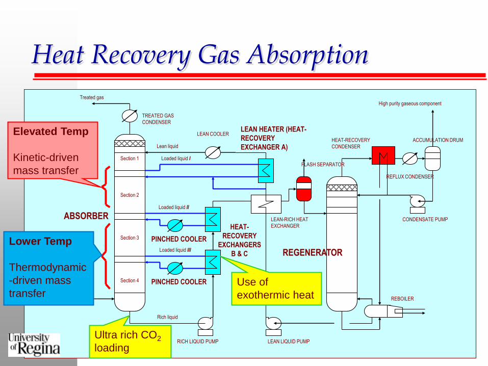
Heat Recovery Gas Absorption
ABSORBER
REGENERATOR
LEAN-RICH HEAT
EXCHANGER
LEAN HEATER (HEAT-
RECOVERY
EXCHANGER A)
HEAT-
RECOVERY
EXCHANGERS
B & C
HEAT-RECOVERY
CONDENSER
Section 1
Section 2
Section 3
Section 4
Lean liquid
Loaded liquid I
Loaded liquid II
Loaded liquid III
Rich liquid
Gas
TREATED GAS
CONDENSER
Treated gas
LEAN COOLER
PINCHED COOLER
PINCHED COOLER
RICH LIQUID PUMP LEAN LIQUID PUMP
CONDENSATE PUMP
REBOILER
REFLUX CONDENSER
FLASH SEPARATOR
ACCUMULATION DRUM
High purity gaseous component
Ultra rich CO2
loading
Use of
exothermic heat
Elevated Temp
Kinetic-driven
mass transfer
Lower Temp
Thermodynamic
-driven mass
transfer

Objective
Simulate the Heat Recovery Gas Absorption
process (Economic-Technical process model)
Evaluate performance and energy consumption
Compare with typical process scheme

GdY
dzIk a
Py
HCI
A
L
o
e
A i
A L
,
,
GdY
dzk a P y yI
A
G A e A A i , ,
GdY
dzk a P y yI
S
G S e S S i , ,
GdY
dz
L dC
dzI
A
AB
B
G Y CdT
dzh a T TI j p j
j
G
G e G L,
LCdT
dzG Y C
dT
dzG H
dY
dzG H
dY
dzp L
L
I j p jj
G
I R
A
I S
S
, ,
Mass-Transfer:
Energy Balance:
Heat-Transfer:
Material Balance:
Methodology
Input
Information
Result
Representation
Process Flow Model &
Simulator
(Different Process Flow
scheme)
Rate Based Sub-Model
•Absorber design
•Regenerator design
•CO2-Amine reaction
Thermodynamic Model
•Vapor-liq equilibrium
•Speciation
Equipment Design Model
•Pump, blower
•Cooler, heat-exchanger
•Condenser, reboiler
Property Model
(Gas + Liquid)
•Viscosity, density
•Vapor pressure
•Others
Steam Property Model
•Enthalpy, entropy,
•Others
Process flow model (Absorption process)

Process simulation
Simulation conditions: Gas stream Coal-fired flue gas (16% CO2)
Process capacity 1,000 tonne CO2/day
CO2 capture efficiency 90%
Absorption solvent Aqueous MEA solution
Solvent concentration 5.0 kmol/m3
CO2 content after regen. 0.15-0.24 mol CO2/mol MEA
Reboiler temperature 110-120oC
Simulation results:
Dimensions of ABSORBER and REGENERATOR
Heat Exchanger / Reboiler / Condenser / Cooler
Pump / Blower / Storage Tank
Temp. & Conc. Profiles / Equilibrium & Operating Lines
Design & Utility Consumption
Design & Electricity Consumption

Simulation results
Heat Recovery Exchanger-B
Cooling duty = 2.5107 kcal/hr
Rich Amine
T = 27.0oC
Lean Amine
T = 40oC
T = 37.4oC
T = 77.2oC
T = 84.1oC
T = 42.4oC
T = 20oC
T = 20oC
T = 32.0oC
T = 32.2oC
T = 46.7oC T = 74.6oC
Heat Recovery Exchanger-A
Heating duty = 1.7107 kcal/hr
Heat Recovery Exchanger-C
Cooling duty = 5.9106 kcal/hr
0
10
20
30
40
50
60
70
0 10 20 30 40 50 60 70 80 90
Liquid Temperature (oC)
Co
lum
n h
eig
ht
fro
m b
ott
om
(m
)
27oC at column
bottom
40oC at column top
0
2
4
6
8
10
12
14
16
0 0.1 0.2 0.3 0.4 0.5 0.6 0.7
CO2 loading (mol/mol)
Pc
o2
(k
Pa
)
Operating
Equilibrium
CO2 loading of 0.59
mol/mol at column
bottom
Temp Profile
0
2
4
6
8
10
12
14
16
18
0 10 20 30 40 50 60 70 80
Temp (C)
Col
umn
heig
ht (m
)
0
2
4
6
8
10
12
14
16
0 0.1 0.2 0.3 0.4 0.5 0.6
CO2 loading (mol/mol)
Pco2
(kPa
)
Operating
Equilibrium

Energy consumption
Energy Requirement Comparison
-
20,000
40,000
60,000
80,000
100,000
0.1 0.15 0.2 0.25 0.3
Lean CO2 Loading (mol/mol)
En
erg
y R
eq
uir
em
en
t (B
TU
/lb
-mo
l C
O2)
Conventional
This Invention
Energy Saving: 30 – 50 %
CO2 rich loading:
Conventional Process 0.45 mol/mol
Heat Recovery Process 0.55 mol/mol
CO2 flashing before Regen: 30 %
Amine circulation rate:
Conventional Process 570 – 740 m3/h
Heat Recovery Process 440 – 550 m3/h

Integration to power plant
Components • Coal-fired boiler & Air pre-heater • HP – IP – LP steam turbines • Feed water heater (FWHs) • Low pressure condenser • Boiler feed water pump
Principles • Coal combustion & chemistry • Heat transfer • Thermodynamics of steam cycle
Output • Coal consumption • Thermal efficiency & Net efficiency • Electricity output • Steam quality and flow rate • Emission rate • Flue gas temperature • Flue gas composition
Power-Cycle Module CO2 Capture Module
Design Model • Absorber
• Regenerator + reboiler
• Flue gas blower
• Cooler + heat exchanger
• Pump + piping system
• Storage tank
Output Design specifications
Energy consumption
Utility consumption
Capital & operating cost
$/tonne CO2
Gas conditions
Design Spec. Capture efficiency
Solvent type
Packing type
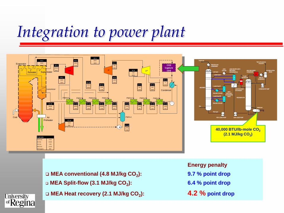
Integration to power plant
Energy penalty
MEA conventional (4.8 MJ/kg CO2): 9.7 % point drop
MEA Split-flow (3.1 MJ/kg CO2): 6.4 % point drop
MEA Heat recovery (2.1 MJ/kg CO2): 4.2 % point drop
ST-5
ST-4 ST-3 6000
6000 6000 3669 ST-7
3105.65 ST-1 3106 460
28500 2961
3503 ST-8
440
2952
ST-2 ST-6
9400 1200 ST-11
3224 ST-12 3183 5
4000 ST-13 ST-9 ST-10 2304
3026 1200 420 300
2788 2945 2889
ST-24 ST-23 ST-22 ST-21 ST-20 ST-18 ST-17 ST-16 ST-15
28500 28500 28500 28500 28500 1000 1000 1000 1000
1563 1445 1386 1368 821 576 569 518 216
ST-14
1000
982 ST-19
1000
759
FLUE GAS
CO2 (%) 13.61
N2 (%) 69.85
O2 (%) 3.50
H2O (%) 12.96
SO2 (ppm) 887
HP IP LP
Condenser
FWH-1FWH-2FWH-3FWH-5
FWH-4
FWH-6FWH-7FWH-8
Economizer
Evaporator
Reheater Superheater
Air
Preheater
CO2
Capture
Unit
Coal
ABSORBER
REGENERATOR
LEAN-RICH HEAT
EXCHANGER
LEAN HEATER (HEAT-
RECOVERY
EXCHANGER A)
HEAT-
RECOVERY
EXCHANGERS
B & C
HEAT-RECOVERY
CONDENSER
Section 1
Section 2
Section 3
Section 4
Lean liquid
Loaded liquid I
Loaded liquid II
Loaded liquid III
Rich liquid
Gas
TREATED GAS
CONDENSER
Treated gas
LEAN
COOLER
PINCHED COOLER
PINCHED COOLER
RICH LIQUID PUMP LEAN LIQUID PUMP
CONDENSATE PUMP
REBOILER
REFLUX
CONDENSER
FLASH
SEPARATOR
ACCUMULATION
DRUM
High purity gaseous
component
40,000 BTU/lb-mole CO2
(2.1 MJ/kg CO2)
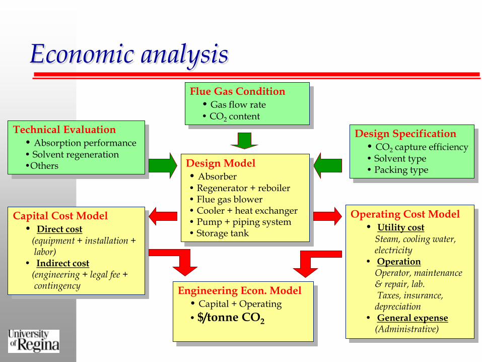
Economic analysis
Technical Evaluation • Absorption performance • Solvent regeneration •Others
Flue Gas Condition • Gas flow rate • CO2 content
Design Specification • CO2 capture efficiency • Solvent type • Packing type
Design Model • Absorber • Regenerator + reboiler • Flue gas blower • Cooler + heat exchanger • Pump + piping system • Storage tank
Capital Cost Model • Direct cost (equipment + installation +
labor) • Indirect cost (engineering + legal fee +
contingency
Operating Cost Model • Utility cost Steam, cooling water,
electricity • Operation Operator, maintenance
& repair, lab. Taxes, insurance,
depreciation • General expense
(Administrative)
Engineering Econ. Model • Capital + Operating
• $/tonne CO2

Cost of CO2 capture Capital Cost (90% capture efficiency; 1000
tonnes/day CO2 feed)
10
12
14
16
18
20
22
24
26
28
0.1 0.15 0.2 0.25 0.3
Lean CO2 Loading (mol/mol)
Fix
ed
Cap
ital
Investm
en
t (M
illi
on
$)
Conventional
This Invention
Operating Cost (90% capture efficiency; 1000
tonnes/day CO2 feed)
4
5
6
7
8
9
10
11
12
0.1 0.15 0.2 0.25 0.3
Lean CO2 Loading (mol/mol)
To
tal
Op
era
tin
g C
ost
(Mil
lio
n $
/ year)
Conventional
This Invention
CO2 Capture Cost (90% capture efficiency;
1000 tonnes/day CO2 feed)
5
10
15
20
25
30
35
40
0.1 0.15 0.2 0.25 0.3
Lean CO2 Loading (mol/mol)
Cap
ture
Co
st
( U
S$/T
on
ne C
O2)
Conventional
This Invention
Lower Capital: 20 – 22 million US$
Lower Operating: 8 – 9 million US$/year
Overall Cost: 16 – 26 % Saving
(Saving = 5 – 10 US$/tonne CO2)
Capital Cost Estimation (US$)
Direct cost
Purchased Equipment
Purchased Equipment + delivery
Purchased Equipment installation
Labor&material for insulating equipment
Instrument and control (installed)
Piping (installed)
Electrical systems (installed)
Building (including services)
Yard Improvements
Service facilities (installed)
Land
TOTAL DIRECT COST
Indirect cost
Engineering and supervision
Construction expenses
Legal expenses
Contractor's fee
Contingency
TOTAL INDIRECT COST
FIXED CAPITAL INVESTMENT (FCI)
WORKING CAPITAL
TOTAL INVESTMENT COST
Product Cost EstimationManufacturing cost
Direct Production Costs
Raw materials
Operating labor
Operating supervision
Electricity
Steam
Process water
Cooling water
Maintenance & Repairs
Operating supplies
Laboratory charges
Royalties
Solvent
Fixed Charges
Depreciation
Property taxes
Interest
Insurance
Rent
Plant Overhead Costs
TOTAL MANUFACTURING COST
General expenses
Administrative costs
Distribution & marketing costs
Research & development costs
TOTAL GENERAL EXPENSES
TOTAL PRODUCT COST
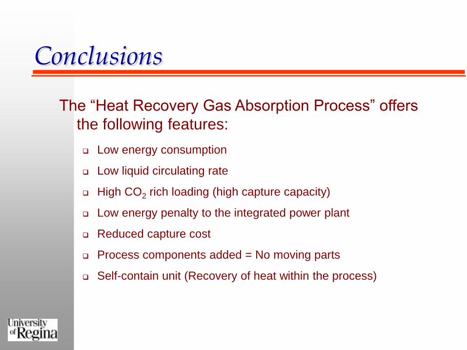
Conclusions
The “Heat Recovery Gas Absorption Process” offers
the following features:
Low energy consumption
Low liquid circulating rate
High CO2 rich loading (high capture capacity)
Low energy penalty to the integrated power plant
Reduced capture cost
Process components added = No moving parts
Self-contain unit (Recovery of heat within the process)

Acknowledgments
Faculty of Engineering and Applied Science, University of
Regina
Research Office, University of Regina
SaskPower
Natural Sciences and Engineering Research Council of
Canada (NSERC)