Modeling and Simulation of Fixed and Variable Speed of · PDF file ·...
9
International Journal of Recent Development in Engineering and Technology Website: www.ijrdet.com (ISSN 2347 - 6435 (Online) Volume 2, Issue 5, May 2014) 52 Modeling and Simulation of Fixed and Variable Speed of DFIG Wind System Rakesh Sharma 1 , Kuldeep Sahay 2 , Sateyndra Singh 3 1 M. Tech. (Student), UP Technical University, Lucknow 2,3 Department of Electrical Engineering, Institute of Engineering & Technology, Lucknow Abstract— The wind power is a pollution free source of energy. In this paper we have focused on analyzing the performance of wind power in conventional system under various scenarios. Here we have introduced a wind power in a power generation and transmission system alongside the conventional 3-phase sources and have simulated its working and performance. The wind power is made to work in tandem with the regular supply. In case of faults occurring in the system wind power is used to act as backup for the original supply. Also in case of extra power demand in peak time periods, it has been used to complement the power sources there by maintaining the power quality and frequency in the system. To analysis the performance of DFIG wind system during three phase fault there is two cases (i) Performance analysis of DFIG during fault at fixed wind speed (ii) Performance analysis of DFIG during fault at variable wind speed. All these scenarios have been simulated with the help of the simulation program using MATLAB and its inbuilt components provided in SIMULINK library. Keywords—Doubly Fed Induction Generator (DFIG), Rotor Side Converter (RSC), Stator Side Converter (SSC), Pulse Width Modulation (PWM), Wound Rotor Induction Generator (WRIG), Voltage Source Converter (VSC). I. INTRODUCTION In last some years more attention has been focused on induction generators for low and medium power application because they have attractive advantages over conventional generators such as low unit cost, less maintenance robust construction etc. One way of generating electricity from renewable sources is to use wind turbines. The most common type of wind turbine is the fixed-speed wind turbine with the induction generator directly connected to the grid. This system has a number of drawbacks, however. The reactive power and, therefore, the grid voltage level cannot be controlled .The DFIG is the same as the WRIG system except that variable resistance in the rotor circuit is replaced by a grid-connected power converter system &there is no need for the soft starter or reactive power compensation and also the power factor is adjusted by power converter itself [1]. The use of convertors also allows bidirectional power flow in the rotor circuit & increase the speed range of the generator (extended generator speed range ±30%), also improved the overall power conversion efficiency. Doubly- Fed Induction Generators (DFIG) are particularly suitable for isolated operation like wind developments. The wind generation includes fixed-speed system as well as variable- speed system [2]. The variable-speed wind power generation is mostly used in wind power generation development because it can operate on the maximum power point of the machine [3, 4]. This system include synchronous and asynchronous generator. In wind turbines based on DFIG, the induction generator stator-side is directly connected to the grid-side and the rotor-side is excited by three phase converter which can regulate both active and reactive power of stator machine through control of dq-axis rotor currents. The rated power of the back-to- back converter is smaller than the induction generator rated power, so that back-to-back converter always specified by the slip power, which is approximately 25% of the rated power of the generator. II. WIND ENERGY Wind energy comes from wind turbine blades and then transferred to a gear box (to match the high speed generator with low speed turbine blades) & the rotor hub to provide mechanical energy to the shaft. The shaft drives the generator to converts the mechanical energy in to electrical energy. The power of an air mass flowing at speed through an area A can be calculated by Power = density of air * swept area * velocity cubed 2 Where, P is power in watts (W), is the air density in kilograms per cubic meter (kg/m 3 ),A is the swept rotor area in square meter (m 2 ),V is the wind speed in meter per second (m/s).But the turbine model is based on the power captured by the blade &converted into mechanical energy.
Transcript of Modeling and Simulation of Fixed and Variable Speed of · PDF file ·...
International Journal of Recent Development in Engineering and Technology
Website: www.ijrdet.com (ISSN 2347 - 6435 (Online) Volume 2, Issue 5, May 2014)
52
Modeling and Simulation of Fixed and Variable Speed of
DFIG Wind System Rakesh Sharma
1, Kuldeep Sahay
2, Sateyndra Singh
3
1M. Tech. (Student), UP Technical University, Lucknow
2,3Department of Electrical Engineering, Institute of Engineering & Technology, Lucknow
Abstract— The wind power is a pollution free source of
energy. In this paper we have focused on analyzing the
performance of wind power in conventional system under
various scenarios. Here we have introduced a wind power in a
power generation and transmission system alongside the
conventional 3-phase sources and have simulated its working
and performance. The wind power is made to work in tandem
with the regular supply. In case of faults occurring in the
system wind power is used to act as backup for the original
supply. Also in case of extra power demand in peak time
periods, it has been used to complement the power sources
there by maintaining the power quality and frequency in the
system. To analysis the performance of DFIG wind system
during three phase fault there is two cases (i) Performance
analysis of DFIG during fault at fixed wind speed (ii)
Performance analysis of DFIG during fault at variable wind
speed. All these scenarios have been simulated with the help of
the simulation program using MATLAB and its inbuilt
components provided in SIMULINK library.
Keywords—Doubly Fed Induction Generator (DFIG),
Rotor Side Converter (RSC), Stator Side Converter (SSC),
Pulse Width Modulation (PWM), Wound Rotor Induction
Generator (WRIG), Voltage Source Converter (VSC).
I. INTRODUCTION
In last some years more attention has been focused on
induction generators for low and medium power
application because they have attractive advantages over
conventional generators such as low unit cost, less
maintenance robust construction etc. One way of
generating electricity from renewable sources is to use
wind turbines. The most common type of wind turbine is
the fixed-speed wind turbine with the induction generator
directly connected to the grid. This system has a number of
drawbacks, however. The reactive power and, therefore, the
grid voltage level cannot be controlled .The DFIG is the
same as the WRIG system except that variable resistance in
the rotor circuit is replaced by a grid-connected power
converter system &there is no need for the soft starter or
reactive power compensation and also the power factor is
adjusted by power converter itself [1].
The use of convertors also allows bidirectional power
flow in the rotor circuit & increase the speed range of the
generator (extended generator speed range ±30%), also
improved the overall power conversion efficiency. Doubly-
Fed Induction Generators (DFIG) are particularly suitable
for isolated operation like wind developments. The wind
generation includes fixed-speed system as well as variable-
speed system [2]. The variable-speed wind power
generation is mostly used in wind power generation
development because it can operate on the maximum
power point of the machine [3, 4]. This system include
synchronous and asynchronous generator. In wind turbines
based on DFIG, the induction generator stator-side is
directly connected to the grid-side and the rotor-side is
excited by three phase converter which can regulate both
active and reactive power of stator machine through control
of dq-axis rotor currents. The rated power of the back-to-
back converter is smaller than the induction generator rated
power, so that back-to-back converter always specified by
the slip power, which is approximately 25% of the rated
power of the generator.
II. WIND ENERGY
Wind energy comes from wind turbine blades and then
transferred to a gear box (to match the high speed generator
with low speed turbine blades) & the rotor hub to provide
mechanical energy to the shaft. The shaft drives the
generator to converts the mechanical energy in to electrical
energy. The power of an air mass flowing at speed
through an area A can be calculated by
Power = density of air * swept area * velocity cubed
2
Where, P is power in watts (W), is the air density in
kilograms per cubic meter (kg/m3),A is the swept rotor area
in square meter (m2),V is the wind speed in meter per
second (m/s).But the turbine model is based on the power
captured by the blade &converted into mechanical energy.
International Journal of Recent Development in Engineering and Technology
Website: www.ijrdet.com (ISSN 2347 - 6435 (Online) Volume 2, Issue 5, May 2014)
53
)/
( )
Where, =0.5, =116/ i, =0.4, =0, =5, =21/ i,
Where PM is the mechanical power output power in
watts & Cp is the power coefficient of the blade which
depends on the tip speed ratio ( ) & blade pitch angle
( ).CP decides how much energy can be captured by wind
turbine system.
To get maximum Cp, in this paper turbine system, for
different wind speeds the pitch angle =0 is fixed.
III. DFIG WIND MODEL AND EQUATIONS
The DFIG typically operates about 30% above & below
synchronous speed, sufficient for most wind speed
conditions. It also enables generator side active power
control & grid side active power control. In the DFIG
model of wind system controlling techniques of power
converters (wind energy power converters) in which the
real and reactive power are controlled separately. The wind
turbine drives DFIG wind system consists of an Induction
generator (WRIG) and an AC/DC/AC IGBT based pulse
width modulated(PWM) converter (back-to-back converter
with dc-link capacitor) or we can say that two levels IGBT
voltage source converter (VSC) system in a back to back
configuration is normally used [3,5]. Since both stator and
rotor can feed power to gird, the generator is known as
doubly fed induction generator (DFIG).It has two main
parts ,the rotor side converter control (RSC), which
controls the torque or active/reactive power of the
generator and, grid side converter controls (GSC), which
controls the DC link voltage and its AC-side reactive
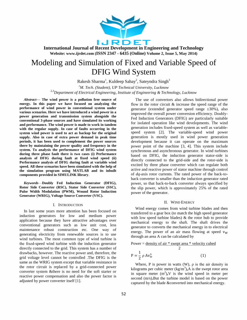
power[6,7]. An equivalent circuit of DFIG wind system in
Fig.1 & Fig. 2a, 2b and relation equations [8] to voltage V,
current I, flux linkage Ψ, and electro-magnetic torque Tem
are as fallows. Fig. 3 & 4 shows the rotor-side converter
control of voltage block diagram and simulink model
respectively and Fig. 5 shows the equivalent circuit of
stator-side converter choke.
Fig.1 Wind Turbine DFIG System Configuration
d-q Reference frame model
Voltage equations
Vs=Vds+j Vqs (5)
Is= Ids+jIqs (6)
Ψs=Ψds+jΨqs (7)
Vr=Vdr+j Vqr (8)
Ir= Idr+jIqr (9)
Ψr=Ψdr+jΨqr (10)
Vds= RsIds− sΨqs+ Ψ
Vqs=RsIqs+ s Ψds+ Ψ
Vdr=RrIdr−s sΨds+ Ψ
Vqr=RrIqr+s sΨdr+ Ψ
Fig.2a d-axis Model
Fig.2b q-axis Model

International Journal of Recent Development in Engineering and Technology
Website: www.ijrdet.com (ISSN 2347 - 6435 (Online) Volume 2, Issue 5, May 2014)
54
Ψds=LsIds+LmId (15) (15)
Ψqs=LsIqs+LmIqr (16)
Ψdr=LrIdr+LmIds (17) (17)
Ψqr=LrIqr+LmIq (18)
Electro-magnetic torque equation
Tem=3np /2 (ΨdsIqs−ΨqsIds) (19)
Where Ls=Lls+Lm (20)
Lr=Llr+Lm (21)
s s = s – r (22)
Ψds=(Vqs−RsIqs)/ s (23)
Ψqs=(Vds−RsIds)/(− s) (24)
Ψs=√ Ψ +√ Ψ
(25)
The subscripts r, s and q, d represents the rotor stator, q-
axis, d- axis components respectively, Tem is electro-
mechanical torque, Lm & J are generator mutual inductance,
and the inertia coefficient, respective.
Idr_ref = -
Ψ (26)
P_ref = Popt− Ploss= Te r (27) (27)
Ploss=Rs +Rr
+Rc +F
(28)
Where Rc, F and Isc, are choke resistance and friction
factor, stator-side converter current. P_ref , Popt and Ploss are
reference active power, desired optimal output active
power and system power loss.
Qo = −Vds(Ψs−LmIqr) /Ls (29)
Qo = −VdsIqs (30)
= RrIdr − s s (LrIqr+LmIqs) (31) (31)
= RrIqr + s s (LrIdr+LmIds) (32)
Vdrc=Vdr = +
(33) (33)
Vqrc=Vqr = +
(34)
Fig. 3 Rotor-Side Converter Control Scheme (Vabc_rc )
Fig.4 Simulink Model of Rotor-Side Converter Voltage ( Vabc_rc )
Fig.5 Equivalent Circuit of Stator Side Converter Choke
Vdsc = Vds−Vdch (35) (35)
Vqsc = Vqs−Vqch (36)
= RcIdsc− sLcIqsc (37) (37)
= RcIqsc+ sLcIdsc (38)
Vdsc = Vds - -
(39) (39)
Vqsc = Vqs - -
(40)
Fig.6 Stator-Side Converter Control Scheme
International Journal of Recent Development in Engineering and Technology
Website: www.ijrdet.com (ISSN 2347 - 6435 (Online) Volume 2, Issue 5, May 2014)
55
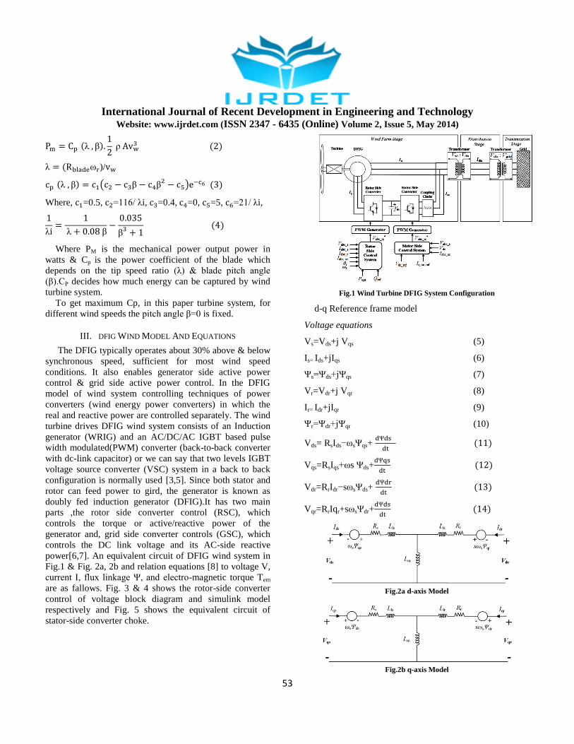
Fig.7 Simulink Model of Stator Side Converter Voltage Vabc_sc
Where the rotor-side converter voltage signals at q-axis
and
& at d-axis and
are generated
through the regulation of currents and cross-coupling parts.
Idr_ref is the rotor-side converter reference current signals,
and
is the coupling part of voltage,
and are determined by regulation of current
Idsc and Iqsc in which the Iqsc_ref (current reference) is given
directly and Idsc_ref is calculated through the regulation of
dc-link voltage Vdc. Vqsc and Vdsc is stator-side converter
voltage signals. Fig. 6 & 7 shows the stator-side converter
control of voltage block diagram of control blocks and
simulink model respectively. Fig. 8 show the complete
connection diagram of control blocks (rotor-side control
and stator-side control).
Fig. 8 Connection Diagram of Control Blocks (RSC and SSC)
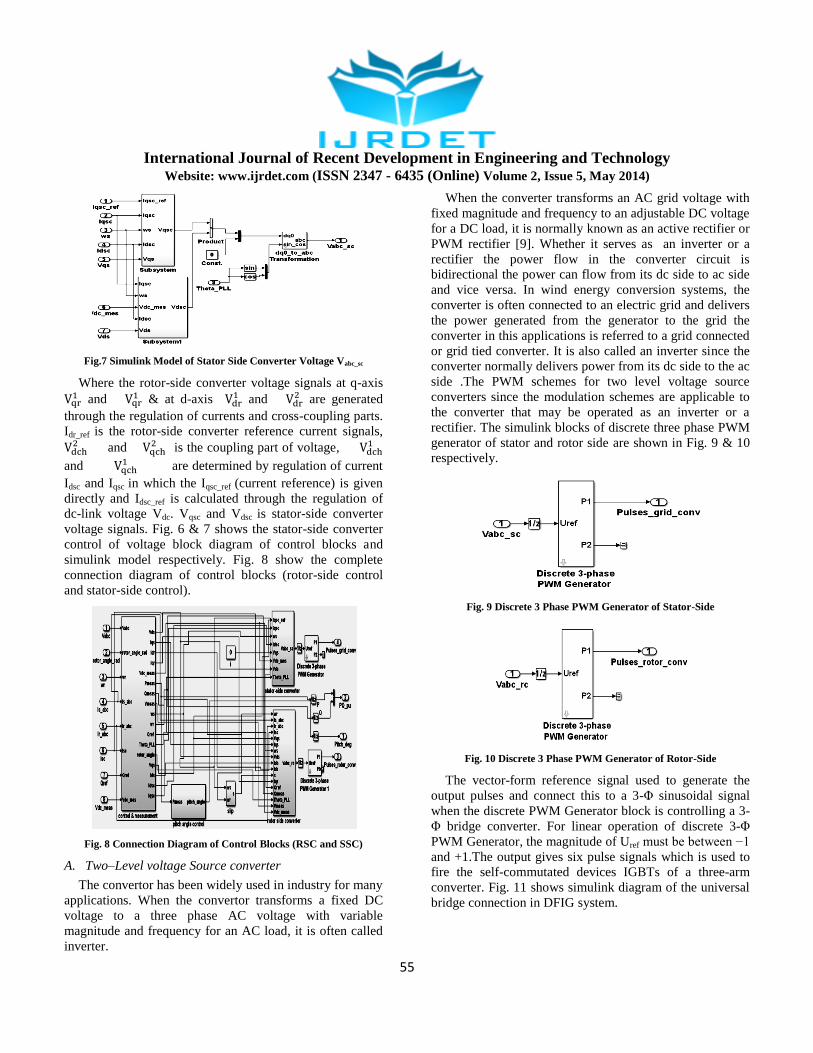
A. Two–Level voltage Source converter
The convertor has been widely used in industry for many
applications. When the convertor transforms a fixed DC
voltage to a three phase AC voltage with variable
magnitude and frequency for an AC load, it is often called
inverter.
When the converter transforms an AC grid voltage with
fixed magnitude and frequency to an adjustable DC voltage
for a DC load, it is normally known as an active rectifier or
PWM rectifier [9]. Whether it serves as an inverter or a
rectifier the power flow in the converter circuit is
bidirectional the power can flow from its dc side to ac side
and vice versa. In wind energy conversion systems, the
converter is often connected to an electric grid and delivers
the power generated from the generator to the grid the
converter in this applications is referred to a grid connected
or grid tied converter. It is also called an inverter since the
converter normally delivers power from its dc side to the ac
side .The PWM schemes for two level voltage source
converters since the modulation schemes are applicable to
the converter that may be operated as an inverter or a
rectifier. The simulink blocks of discrete three phase PWM
generator of stator and rotor side are shown in Fig. 9 & 10
respectively.
Fig. 9 Discrete 3 Phase PWM Generator of Stator-Side
Fig. 10 Discrete 3 Phase PWM Generator of Rotor-Side
The vector-form reference signal used to generate the
output pulses and connect this to a 3-Φ sinusoidal signal
when the discrete PWM Generator block is controlling a 3-
Φ bridge converter. For linear operation of discrete 3-Φ
PWM Generator, the magnitude of Uref must be between −1
and +1.The output gives six pulse signals which is used to
fire the self-commutated devices IGBTs of a three-arm
converter. Fig. 11 shows simulink diagram of the universal
bridge connection in DFIG system.

International Journal of Recent Development in Engineering and Technology
Website: www.ijrdet.com (ISSN 2347 - 6435 (Online) Volume 2, Issue 5, May 2014)
56
Fig. 11 Simulink Diagram of the Universal Bridge Connection in
DFIG System
B. Pitch Angle Control
The pitch angle is calculated by an open loop control of
regulated output real power. Due to the big size of turbine
blades so the pitch angle; inertia has to change to a smooth
rate and a reasonable range. Here Pmeas and Pref. are
connected with summer block then the signal pass to the
discrete type PI controller after that it passes through the
saturation and change rate limiter block then it gives pitch
angle .The simulink model of pitch angle control are
shown in Fig. 12.
Fig. 12 Simulink block diagram of pitch angle control
IV. SIMULINK MODELING OF DFIG WIND SYSTEM
Fig. 13 shows DFIG wind model simulation in
MATLAB/SIM-POWER SIMULINK. The three phase
programmable source is generating power at 120 kV, which
is stepped down to 25 kV by the two winding transformer
and then transmitted by the 30 km long transmission line
for further stepping down the voltage level to the 575 V at
point of common coupling between grid and DFIG wind
energy conversion system. The DFIG wind energy
conversion system is generating power of 1.5 MW.
Fig. 13 Development Test Model for DFIG Wind System
In this, the wind turbine uses a doubly-fed induction
generator (DFIG), which consists of an AC/DC/AC IGBT-
based PWM converter and a wound rotor induction
generator. The dc voltage is applied to IGBT/Diode‗s of
two level inverter. The pulse width modulation technique
has been used in this inverter, in order to achieve higher
accuracy , the carrier frequency or switching frequency is
1620 Hz, discrete sample time is, Ts =5 microseconds. The
stator of Induction generator is connected directly to the 60
Hz grid system whereas the rotor is providing at variable
frequency through the AC/DC/AC converter. The DFIG
wind model allows capturing maximum power to the wind
for low wind speeds through maintaining the turbine speed,
while minimize mechanical stresses on the wind turbine
during the gusts of wind. In this, the reactive power is kept
at 0 Mvar & DC voltage is regulated at 1200 V. When we
double click on wind model block then it shows a
generator, a converter, a turbine, & a drive train and the
control system block.

International Journal of Recent Development in Engineering and Technology
Website: www.ijrdet.com (ISSN 2347 - 6435 (Online) Volume 2, Issue 5, May 2014)
57
A. Case:-1 Performance Analysis of DFIG during Fault at
Fixed Wind Speed
Fig. 14 Simulink Diagram of DFIG Wind System during Fault at
Fixed Speed
The DFIG wind energy system Fig. 14 connected to grid
via transformer and transmission line the DFIG rating is 1.5
MW a three phase short circuit fault (three phase fault
element from Simscape) occur at bus B575 for 0.2 sec
between 0.4 to 0.6 sec and simulated MATLAB simulink
model for 1.2 sec.
B. Effect of Fault on Active Power
Fig. 15 shows that the active power (P) at fault condition
under fixed speed. It can be seen that at the time of fault the
active power becomes zero between 0.4 to 0.6 sec. after
that the active power increasing up to rated value which are
1.5 MW.
Fig. 15 Active Power (P) Versus Time at Fault Condition
C. Effect of Fault on Reactive Power
Fig. 16 shows that the reactive power (Q) at fault
condition under fixed speed.
It can be seen that at the time of fault the reactive power
becomes zero between 0.4 to 0.6 sec. after the fault
clearance reactive power requirement increases up to 0.25
MW and comes in normal state within 0.3 seconds.
Fig. 16 Reactive Power (Q) versus Time at Fault Condition
D. Effect of Fault of Rotor and Stator Current of DFIG
Wind System
Fig. 17 & Fig. 18 shows that the rotor and stator current
of DFIG wind system at fault condition under fixed speed.
It can be seen that at the time of fault between 0.4 sec. to
0.6 sec., both become almost zero (but not zero), before
and after the fault both will become stable.
Fig. 17 Rotor Current of DFIG Wind System at Fault Condition
Fig. 18 Stator Current of DFIG Wind System at Fault Condition
E. Effect of Fault on Grid Side voltage without and with
Filter, DC link Voltage (Vabc, Vdc, Vabc_g)
Fig. 19, 20 & Fig. 21 shows that the Grid Side voltage
without and with Filter, DC link Voltage, (Vabc, Vabc_g, Vdc,)
of DFIG Wind energy System at fault condition under fixed
speed. It can be seen that at the time of fault between 0.4
sec. to 0.6 sec., both become almost zero (but not zero),
before and after the fault both will become stable. It
becomes almost zero (but not exactly zero).

International Journal of Recent Development in Engineering and Technology
Website: www.ijrdet.com (ISSN 2347 - 6435 (Online) Volume 2, Issue 5, May 2014)
58
Before and after the fault they give their regular value at
fix speed, and dc link voltage Vdc remains constant at fault
time 0.4 sec to 0.6 sec before and after.
Fig. 19 Grid Side Voltage with Filter (Vabc) versus Time at Fault
Condition
Fig. 20 Grid Side Voltage without Filter (Vabc_g) versus Time at Fault
Condition
Fig. 21 DC Link Voltage (Vdc) versus Time at Fault Condition
F. Case:-2 Performance Analysis of DFIG during Fault at
Variable Wind Speed
Fig. 22 Simulink Diagram of DFIG Wind System during Fault at
Variable Speed
The DFIG wind energy system Fig. 22 connected to grid
via transformer and transmission line the DFIG rating is 1.5
MW a three phase short circuit fault occur at bus B575 for
0.2 sec between 0.4 to 0.6 sec and simulated MATLAB
simulink model for 1.2 sec.
G. Effect of Fault on Active Power
Fig. 23 shows that the active power (P) at fault condition
under variable wind speed. It can be seen that at the time of
fault the active power becomes zero between 0.4 to 0.6
sec., after that the active power increasing up to rated value
which are 1.5 MW.
Fig. 23 Active Power (P) Versus Time at Fault Condition
H. Effect of Fault on Reactive Power
Fig. 24 shows that the reactive power (Q) at fault
condition under Variable wind speed. It can be seen that
there is no effect of variable wind speed at fault time. At
the time of fault the reactive power becomes zero between
0.4 to 0.6 sec., after the fault clearance system comes in
normal state within 0.02 second (able to provide required
reactive power).
Fig. 24 Reactive Power (Q) versus Time at Fault Condition
I. Effect of Fault of Rotor and Stator Current of DFIG
Wind System
Fig. 25 & Fig. 26 show that the Rotor and Stator Current
of DFIG Wind System at fault condition under Variable
wind speed. It can be seen that there is no effect of variable
wind speed at fault time. At the time of fault between 0.4
sec. to 0.6 sec., both become almost zero (but not zero),
before and after the fault both will become stable.

International Journal of Recent Development in Engineering and Technology
Website: www.ijrdet.com (ISSN 2347 - 6435 (Online) Volume 2, Issue 5, May 2014)
59
Fig. 25 Rotor Current of DFIG Wind System at Fault Condition
Fig. 26 Stator Current of DFIG Wind System at Fault Condition
J. Effect of Fault on Grid Side voltage without and with
Filter, DC link Voltage (Vabc, Vdc, Vabc_g)
Fig. 27, 28 & Fig. 29 shows that the Grid Side voltage
without and with Filter, DC link Voltage, (Vabc, Vabc_g, Vdc,)
of DFIG Wind energy System at fault condition under fixed
speed. It can be seen that there is no effect of variable wind
speed at fault time. At the time of fault between 0.4 sec. to
0.6 sec., both become almost zero (but not zero), before
and after the fault both will become stable. It becomes
almost zero (but not exactly zero). Before and after the
fault they give their regular value at fix speed, and dc link
voltage Vdc remains constant at fault time 0.4 sec. to 0.6
sec. before and after.
Fig. 27 Grid Side Voltage with Filter (Vabc) versus Time at Fault
Condition
Fig. 28 Grid Side Voltage without Filter (Vabc_g) versus Time at Fault
Condition
Fig. 29 DC Link Voltage (Vdc) versus Time at Fault Condition
V. CONCLUSION
A DFIG wind system are modeled and simulated in
MATLAB software .An active power versus rotor speed
relationship is analyses for the wind turbine model, In
SCIG we know that requires external reactive power to
support gird side voltage and it can maintain the real power
at nominal level by pitch control but cannot vary the rotor
speed to get maximum wind power at different wind speed
.In our DFIG wind system there is no need to reactive
power compensators to maintained the distribution line
voltage and make optimal active power controlling. Here
we employed both side (stator-side & rotor-side) voltage
control techniques .The steady state and dynamic response
of the DFIG wind system are calculated .It is concluded
that the variable speed wind energy system has ability of
optimal active power control & the efficiency became
much higher of that system. It can be seen that the dc-link
voltage maintain constant during fault.
REFERENCES
[1] Pehosh M., Putnam R., ―Interconnection Of Large Wind Turbines To Electric Cooperative Distribution Grids‖, Rural Electric Power
Conference (REPC), IEEE 2010.
[2] R. Datta and V. T. Ranganathan, ―Variable-Speed Wind Power
Generation Using Doubly Fed Wound Rotor Induction – A
Comparison with Alternative Schemes,‖ IEEE Trans. Energy Conversion, vol. 17, no. 3, pp. 414-421, Sept. 2002.
[3] R.Pena, J.C. Clare and G.M.Asher, ―Doubly Fed Induction
Generator Using Back To Back PWM Converters And Its Application To Variable Speed Wind Energy Generation‖ ,IEE
Proc.-Electr.Power Appl. Vol. 143 ,no.3, pp. 231-241,May 1996.
[4] B.H. Chowdhury and S. Chellapilla, ―Double-Fed Induction
Generator Control for Variable Speed Wind Power Generation,‖
Electric Power Systems Research, vol. 76, iss. 9-10, pp. 786-800, June 2006.
[5] Bharat Singh, S.N. Singh,‖ Wind Power Interconnection into the
Power System: A Review of Grid Code Requirements‖, the electricity journal, Science direct, vol 22, issue 5, June 2009.
[6] Mustafa Kayıkc and Jovica V. Milanovi´,‖ ―Reactive Power Control Strategies for DFIG-Based Plants‖, IEEE transactions on energy
conversion, vol. 22, no. 2, June 2007.

International Journal of Recent Development in Engineering and Technology
Website: www.ijrdet.com (ISSN 2347 - 6435 (Online) Volume 2, Issue 5, May 2014)
60
[7] S. N. Singh, Jacob Østergaard, and Bharat Singh, ―Reactive Power
Capability of Unified DFIG for Wind Power Generation‖,IEEE
2010.
[8] Rakesh Sharma, Kuldeep Sahay, Satyendra Singh, ―Effects of
Varying Load on DC-Link Voltage in DFIG Wind Energy Conversion System‖, International Journal of Advanced Research in
Electrical, Electronics and Instrumentation Engineering, vol. 3, Issue
5, May 2014.
[9] J. Carrasco, L. Franquelo, J. Bialasiewicz, E. Galvan, R. Guisado,
M. Prats, J. Leon, and N. Moreno-Alfonso, ―Power-electronic
systems for the grid integration of renewable energy sources: A
survey,‖ IEEE Trans. Industrial Electronics, vol. 53, no. 4, pp. 1002–
1016, Jun. 2006.
BIOGRAPHY
Rakesh Sharma is a M. Tech student in the
Department of Electrical Engineering, IET, and
Lucknow. He received his B.Tech degree in Electrical Engineering from UP Technical University, Lucknow,
India. He has total 04 years of teaching experience in
IET, Lucknow, His research area of interest includes DFIG wind energy conversion system, fault analysis
and performance enhancement.
Kuldeep Sahay, Ph.D. is associated with Institute
of Engineering & Technology, Lucknow since 1996,
where, he is presently Professor in the Department of Electrical Engineering, An Autonomous Constituent
College of Gautam Buddh Technical University
(Formerly Uttar Pradesh Technical University), and Lucknow. He has authored numbers of research paper
in National and International Journal having good citation and published a
book. His research interests are in the area of Mathematical Modeling of Energy Storage System, Integration of Renewable Energy System with
Grid. Prof. Sahay for his overall contribution in research and academics
has been awarded ―Shiksha Rattan Puraskar‖ and ―Rashtriya Gaurav Award‖ by India International Friendship Society, New Delhi in 2011.
Sateyndra Singh, M. Tech. is associated with Institute of Engineering & Technology, Lucknow
since 2008, where, he is presently Assistant Professor
in the Department of Electrical Engineering, An Autonomous Constituent College of Gautam Buddh
Technical University (Formerly Uttar Pradesh
Technical University), and Lucknow. He has authored numbers of research paper in National and International Journal having
good citation. His research interests are in the area of power systems.