Modeling and Nonlinear Seismic Analysis of Framed Structures Equipped with Damped Braces
6
Modeling and Nonlinear Seismic Analysis of Framed Structures Equipped with Damped Braces MAZZA FABIO, VULCANO ALFONSO, MAZZA MIRKO, MAURO GIUSEPPE Dipartimento di Strutture Universitá della Calabria 87036, Rende (Cosenza) ITALY [email protected], [email protected], [email protected], [email protected] Abstract: - The supplementary energy dissipation represents an efficient technique for the seismic protection of structural systems. Specifically, the insertion of steel braces equipped with damping devices proves to be effective in order to enhance the performance of a framed building under horizontal seismic loads. In the last decades several applications were experienced in many countries, adopting damping systems with different characteristics, depending on both arrangement of the damped braces and kind of damping devices. In this paper, the attention is focused on the modeling and nonlinear seismic analysis of framed structures equipped with friction, metallic yielding, viscoelastic and viscous dampers. To check the effectiveness of the damped braces, a six-storey reinforced concrete (r.c.) structure, representative of a symmetric framed building, designed in a medium-risk seismic region, is supposed to be retrofitted as in a high-risk seismic region. Key-Words: - Framed buildings, damped braces, friction dampers, hysteretic dampers, viscoelastic dampers, viscous dampers. 1 Introduction Among the techniques of passive control that have had in the last two decades real application for the control of the seismic response of buildings, that based on the dissipation of a large portion of the energy transmitted by the earthquake to the structure can be considered very effective. Actually a wide variety of energy dissipating devices is available for the passive control of vibrations [1-6]. The extra cost of the damped braces is widely recovered by the achievable advantages: high level of seismic protection of a framed structure, considerable reduction of the reparations required after a strong earthquake, functionality and practicability of the buildings even after a such earthquake. In the case of seismic retrofitting the properties of the framed structure are known previously, while for the seismic design of a new structure it is necessary to select, starting from the level of protection assigned for the unbraced frame, the properties of the frame itself as well as those of braces and dampers. For a widespread application of supplemental dampers, comprehensive analysis, design and testing guidelines should be available. New seismic codes (e.g., Italian code 2008, NTC08, [7]) allow for the use of dissipative braces for the seismic retrofitting of framed buildings, while only few codes provide simplified criteria for their design (e.g., FEMA 356, 2000, [8]). After a brief description of the arrangements of damped braces to be inserted in framed buildings, features and limitations of the considered damper models are discussed. Then, the results of an analytical study are presented comparing the nonlinear dynamic responses of a six-storey r.c. framed building before and after retrofitting by hysteretic damped braces. 2 Modeling The damped braces available in literature differ for the features of the supplemental damping devices and/or for the particular arrangement of the braces supporting them, using classical (e.g. cross braces, Fig. 1a; single diagonal brace, Fig. 1b; chevron braces, Fig. 1c), geometrically amplified (e.g. toggle-brace, Fig. 1d; scissor-jack, Fig. 1e). The supplemental damping devices may be classified in: displacement-dependent (e.g., friction damper, FR; metallic-yielding damper, YL), velocity-dependent (e.g., viscoelastic damper, VE; viscous damper, VS) and self-centring (e.g. shape memory alloys, SMA). Apart from the system in Fig. 1a, where the braces are assumed to be slender enough to buckle elastically (practically negligible buckling load), in the other systems depicted in Figs. 1b-1d the braces are designed not to buckle. For clarity, referring to the schemes in Fig. 1, the properties of the system at a storey are indicated in what follows: K B is the Recent Researches in Information Science and Applications ISBN: 978-1-61804-150-0 280
Transcript of Modeling and Nonlinear Seismic Analysis of Framed Structures Equipped with Damped Braces

Modeling and Nonlinear Seismic Analysis of Framed Structures
Equipped with Damped Braces
MAZZA FABIO, VULCANO ALFONSO, MAZZA MIRKO, MAURO GIUSEPPE
Dipartimento di Strutture
Universitá della Calabria
87036, Rende (Cosenza)
ITALY
[email protected], [email protected], [email protected], [email protected]
Abstract: - The supplementary energy dissipation represents an efficient technique for the seismic protection of
structural systems. Specifically, the insertion of steel braces equipped with damping devices proves to be
effective in order to enhance the performance of a framed building under horizontal seismic loads. In the last
decades several applications were experienced in many countries, adopting damping systems with different
characteristics, depending on both arrangement of the damped braces and kind of damping devices. In this
paper, the attention is focused on the modeling and nonlinear seismic analysis of framed structures equipped
with friction, metallic yielding, viscoelastic and viscous dampers. To check the effectiveness of the damped
braces, a six-storey reinforced concrete (r.c.) structure, representative of a symmetric framed building, designed
in a medium-risk seismic region, is supposed to be retrofitted as in a high-risk seismic region.
Key-Words: - Framed buildings, damped braces, friction dampers, hysteretic dampers, viscoelastic dampers,
viscous dampers.
1 Introduction Among the techniques of passive control that have
had in the last two decades real application for the
control of the seismic response of buildings, that
based on the dissipation of a large portion of the
energy transmitted by the earthquake to the structure
can be considered very effective. Actually a wide
variety of energy dissipating devices is available for
the passive control of vibrations [1-6]. The extra
cost of the damped braces is widely recovered by
the achievable advantages: high level of seismic
protection of a framed structure, considerable
reduction of the reparations required after a strong
earthquake, functionality and practicability of the
buildings even after a such earthquake.
In the case of seismic retrofitting the properties
of the framed structure are known previously, while
for the seismic design of a new structure it is
necessary to select, starting from the level of
protection assigned for the unbraced frame, the
properties of the frame itself as well as those of
braces and dampers. For a widespread application of
supplemental dampers, comprehensive analysis,
design and testing guidelines should be available.
New seismic codes (e.g., Italian code 2008, NTC08,
[7]) allow for the use of dissipative braces for the
seismic retrofitting of framed buildings, while only
few codes provide simplified criteria for their design
(e.g., FEMA 356, 2000, [8]).
After a brief description of the arrangements of
damped braces to be inserted in framed buildings,
features and limitations of the considered damper
models are discussed. Then, the results of an
analytical study are presented comparing the
nonlinear dynamic responses of a six-storey r.c.
framed building before and after retrofitting by
hysteretic damped braces.
2 Modeling The damped braces available in literature differ for
the features of the supplemental damping devices
and/or for the particular arrangement of the braces
supporting them, using classical (e.g. cross braces,
Fig. 1a; single diagonal brace, Fig. 1b; chevron
braces, Fig. 1c), geometrically amplified (e.g.
toggle-brace, Fig. 1d; scissor-jack, Fig. 1e). The
supplemental damping devices may be classified in:
displacement-dependent (e.g., friction damper, FR;
metallic-yielding damper, YL), velocity-dependent
(e.g., viscoelastic damper, VE; viscous damper, VS)
and self-centring (e.g. shape memory alloys, SMA).
Apart from the system in Fig. 1a, where the braces
are assumed to be slender enough to buckle
elastically (practically negligible buckling load), in
the other systems depicted in Figs. 1b-1d the braces
are designed not to buckle. For clarity, referring to
the schemes in Fig. 1, the properties of the system at
a storey are indicated in what follows: KB is the
Recent Researches in Information Science and Applications
ISBN: 978-1-61804-150-0 280

elastic stiffness of the brace; KD and CD are the
elastic stiffness and viscous damping of the damper;
KF and CF are the elastic stiffness and viscous
damping of the frame. To simulate the behaviour of
braced frames equipped with damping devices,
suitable analytical models should be adopted.
(a)
(b)
(c)
(d)
(e)
Figure 1. Typical arrangements of damped braces.
In addition, the models should be relatively
simple to carry out the analysis with a reasonable
computational effort.
In what follows aspects of the analytical
modeling are discussed only with reference to
devices with displacement- and velocity-dependent
damping [9, 10].
2.1 Displacement-dependent damping FR and YL dampers have a stable hysteretic
behaviour and present a mechanism of energy
dissipation depending on the storey drifts; their
activation happens when preset stress levels are
reached or overcome. Using the cross-bracing
system shown in Fig. 1a, either FR device in Fig. 2a
or YL device in Fig. 3a, which are based on the
same mechanism, have been adopted. The single
diagonal system in Fig. 1b can be adopted for
axially stressed devices, such as: the friction damper
in Fig. 2b; the buckling-resistant unbonded brace
(Fig. 3c), consisting of a core steel plate encased in
a concrete filled steel tube (metallic-yielding of the
interior component under reversal axial loads
provides stable energy dissipation, while the
exterior concrete-filled steel tube prevents local and
member buckling). Moreover, damping devices can
be also located between the top of chevron braces
and beam mid-span (Fig. 1c), e.g.: a FR device of
the kind in Fig. 2c; a YL device, consisting of
multiple X-shaped steel plates (Fig. 3b).
(a) (b)
(c)
(d)
Figure 2. Typical friction (FR) dampers and their
modeling and idealized response.
As shown in Fig. 3d, the behaviour of a YL
device can be idealized by a bilinear law, which
specializes as a rigid-plastic one for a FR device
(Fig. 2d).
The design parameters of the FR and YL
dampers are synthetically reported below:
(a) FR damper: Ny=slip load;
Recent Researches in Information Science and Applications
ISBN: 978-1-61804-150-0 281
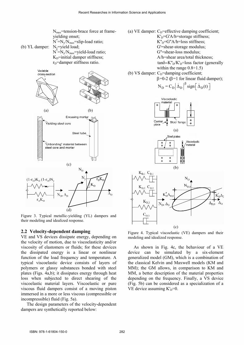
Nmax=tension-brace force at frame-
yielding onset;
N*=Ny/Nmax=slip-load ratio;
(b) YL damper: Ny=yield load;
N*=Ny/Nmax=yield-load ratio;
KD=initial damper stiffness;
rD=damper stiffness ratio.
(a) (b)
(c)
(d)
Figure 3. Typical metallic-yielding (YL) dampers and
their modeling and idealized response.
2.2 Velocity-dependent damping VE and VS devices dissipate energy, depending on
the velocity of motion, due to viscoelasticity and/or
viscosity of elastomers or fluids; for these devices
the dissipated energy is a linear or nonlinear
function of the load frequency and temperature. A
typical viscoelastic device consists of layers of
polymers or glassy substances bonded with steel
plates (Figs. 4a,b); it dissipates energy through heat
loss when subjected to direct shearing of the
viscoelastic material layers. Viscoelastic or pure
viscous fluid dampers consist of a moving piston
immersed in a more or less viscous (compressible or
incompressible) fluid (Fig. 5a).
The design parameters of the velocity-dependent
dampers are synthetically reported below:
(a) VE damper: CD=effective damping coefficient;
K'D=G'A/h=storage stiffness;
K''D=G''A/h=loss stiffness;
G'=shear-storage modulus;
G''=shear-loss modulus;
A/h=shear area/total thickness;
tanδ=K''D/K'D=loss factor (generally
within the range 0.8÷1.5)
(b) VS damper: CD=damping coefficient;
β=0-2 (β=1 for linear fluid damper);
β
D D D DN = C ∆ sign ∆ (t) ɺ ɺ
(a)
(b)
(c)
Figure 4. Typical viscoelastic (VE) dampers and their
modeling and idealized response.
As shown in Fig. 4c, the behaviour of a VE
device can be simulated by a six-element
generalized model (GM), which is a combination of
the classical Kelvin and Maxwell models (KM and
MM); the GM allows, in comparison to KM and
MM, a better description of the material properties
depending on the frequency. Finally, a VS device
(Fig. 5b) can be considered as a specialization of a
VE device assuming K'D=0.
Recent Researches in Information Science and Applications
ISBN: 978-1-61804-150-0 282

(a)
(b)
Figure 5. Typical viscous (VS) damper and its modeling
and idealized response.
3 Method of analysis A computer code was prepared in order to simulate
the response of reinforced concrete (r.c.) framed
building with damped braces. To simulate the
behaviour of the r.c. frame member, a lumped
plasticity model constituted of two components (one
elastic-perfectly plastic and the other elastic-linear)
is considered, assuming a bilinear moment-
curvature law with a suitable value of hardening
ratio (e.g., 2%). The effect of the axial load on the
ultimate bending moment of the columns (M-N
interaction) is also considered, assuming fully
elastic axial strains, while the shear deformation is
neglected. At each step of the analysis, the elastic-
plastic solution is evaluated in terms of the initial
state and the incremental load on the basis of a
holonomic law, as a solution of the Haar-Kàrmàn
principle.
The nonlinear seismic analysis is carried out by a
step-by-step procedure satisfying the dynamic
equilibrium:
( ) ( ) ( ) ( )gt t t u t + + =− Mu Cu f u M i ɺɺ ɺ ɺɺ (1)
For this purpose, a nonlinear implicit system in the
unknown velocity vector uɺ is used, being: M the
mass matrix, u and ü the displacement and
acceleration vectors, f the structural reaction vector,
i the vector of the influence coefficient and üg the
horizontal ground acceleration; according to the
Rayleigh hypothesis, the damping matrix C is
assumed to be a linear combination of the mass and
the stiffness matrices, assuming a suitable damping
ratio (e.g. 5%) associated with two control
frequencies (or modes). More precisely, to obtain
the solution of Eq. (1), the following residual
iteration scheme is used [11]:
( ) ( )(j) (j)(j)0 0 0 11 1
1 1- t t
2 2
= + −α ∆ − + +α ∆ −
r q q s p s p
(j 1) (j) (j)1 1
+ =u u -Hrɺ ɺ (2a,b)
in which the indexes 0 and 1 refer, respectively, to
the beginning and the end of the generic time step,
q=Muɺ is the momentum vector, s=f[u]+Cuɺ , while
α and β are suitable functions of the time step ∆t.
The convergence of the iterative process is assured
adopting the iteration matrix -1
2E
1 1 1t t
2 2 2β
= + +α + ∆ + +α ∆
H M K C (3)
where KE is the elastic stiffness matrix.
4 Design and seismic analysis of the
unbraced and damped braced frames A typical six-storey residential building with a r.c.
framed structure (Fig. 6a) is considered as primary
structure. The primary framed building is designed
according to the Italian Seismic Code in force in
1996 [12], for a medium-risk seismic region
(seismic coefficient: C=0.07) and a typical subsoil
class (main coefficients: R=ε=β=1). The gravity
loads are represented by a dead load of 4.2 kN/m2 at
the top floor and 5.0 kN/m2 at the other floors, and a
live load of 2.0 kN/m2 at all the floors. Masonry
infill walls, regularly distributed in elevation along
the perimeter (see Fig. 6a), are considered assuming
an average weight of about 2.7 kN/m2. The design is
carried out to comply with the ultimate limit states.
Detailing for local ductility is also imposed to
satisfy minimum conditions for the longitudinal bars
of the r.c. frame members. Further detail can be
found in a previous work by the authors [13].
For the purpose of retrofitting the test structure
from a medium-risk region up to a high-risk seismic
region, diagonal steel braces equipped with dampers
are inserted, at each storey, as indicated in Figs. 6b
and 6c. For brevity, only the case of YL dampers
(HY damped braces) is considered. The design of
the damped braces is carried out considering seismic
loads provided by NTC08 for a high-risk seismic
region (peak ground acceleration on rock: ag=0.27g;
maximum spectrum amplification coefficient:
F0=2.5) and subsoil class B on a level ground (site
amplification factor: S=SSST=1.13; PGA=1.13x
0.27g=0.31g). The following values are assumed for
design: ductility of the frame, µF=1.5, and stiffness
hardening ratio, rF=0%; ductility of the damper,
µD=10, and stiffness hardening ratio, rD=0%. Details
on the design procedure can be found in previous
Recent Researches in Information Science and Applications
ISBN: 978-1-61804-150-0 283
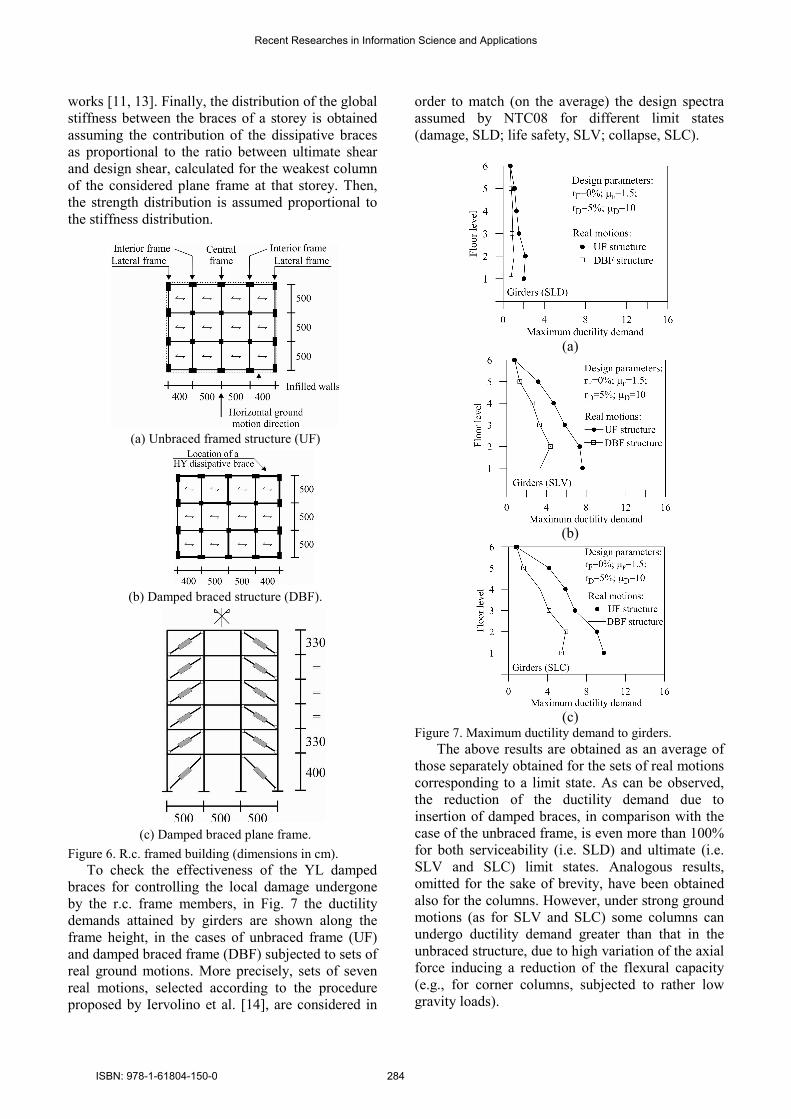
works [11, 13]. Finally, the distribution of the global
stiffness between the braces of a storey is obtained
assuming the contribution of the dissipative braces
as proportional to the ratio between ultimate shear
and design shear, calculated for the weakest column
of the considered plane frame at that storey. Then,
the strength distribution is assumed proportional to
the stiffness distribution.
(a) Unbraced framed structure (UF)
(b) Damped braced structure (DBF).
(c) Damped braced plane frame.
Figure 6. R.c. framed building (dimensions in cm).
To check the effectiveness of the YL damped
braces for controlling the local damage undergone
by the r.c. frame members, in Fig. 7 the ductility
demands attained by girders are shown along the
frame height, in the cases of unbraced frame (UF)
and damped braced frame (DBF) subjected to sets of
real ground motions. More precisely, sets of seven
real motions, selected according to the procedure
proposed by Iervolino et al. [14], are considered in
order to match (on the average) the design spectra
assumed by NTC08 for different limit states
(damage, SLD; life safety, SLV; collapse, SLC).
(a)
(b)
(c)
Figure 7. Maximum ductility demand to girders.
The above results are obtained as an average of
those separately obtained for the sets of real motions
corresponding to a limit state. As can be observed,
the reduction of the ductility demand due to
insertion of damped braces, in comparison with the
case of the unbraced frame, is even more than 100%
for both serviceability (i.e. SLD) and ultimate (i.e.
SLV and SLC) limit states. Analogous results,
omitted for the sake of brevity, have been obtained
also for the columns. However, under strong ground
motions (as for SLV and SLC) some columns can
undergo ductility demand greater than that in the
unbraced structure, due to high variation of the axial
force inducing a reduction of the flexural capacity
(e.g., for corner columns, subjected to rather low
gravity loads).
Recent Researches in Information Science and Applications
ISBN: 978-1-61804-150-0 284
5 Concluding remarks A step-by-step procedure for nonlinear seismic
analysis of framed structures equipped with damped
braces was presented. For this purpose, suitable
models were adopted for simulating the response of
a frame member and that of different kinds of
dampers (friction, metallic yielding, viscoelastic,
viscous) under strong ground motions. To show the
effectiveness and potentiality of the above
procedure, the results of nonlinear dynamic analyses
were presented comparing the responses of a six-
storey r.c. framed building, primarily designed in a
medium-risk seismic region, and successively
retrofitted as in a high-risk seismic region by
insertion of braces equipped with YL dampers.
Acknowledgement:
The present work was financed by RELUIS (Italian
network of university laboratories of earthquake
engineering), according to “convenzione D.P.C. –
RELUIS 2010-2013, task 2.3.2”.
References:
[1] Soong T.T., Dargush G.F., Passive energy
dissipation systems in structural engineering
John Wiley & Sons, Chichester, England, 1997.
[2] Christopoulos C., Filiatrault A., Principles of
passive supplemental damping and seismic
isolation. IUSS Press, Istituto Universitario di
Studi Superiori di Pavia (Italy), 2006.
[3] Mazza, F., Vulcano A., Sistemi di controllo
passivo delle vibrazioni, in Progettazione
sismo-resistente di edifici in cemento armato
(in italian), Città Studi Edizioni, Novara (Italy),
Vol. 11, pp. 525-575, 2011.
[4] Ponzo F.C., Di Cesare A., Nigro D., Vulcano
A., Mazza F., Dolce M., Moroni C., JET-PACS
project: dynamic experimental tests and
numerical results obtained for a steel frame
equipped with hysteretic damped chevron
braces, Journal of Earthquake Engineering,
Vol. 16, pp. 662-685, 2012.
[5] Baratta A., Corbi I., Corbi O., Barros R.C.,
Bairrão R., Shaking table experimental
researches aimed at the protection of structures
subject to dynamic loading, The Open
Construction and Building Technology Journal,
Vol. 6, pp. 355-360, 2012.
[6] Tirca L.D., Foti D., Diaferio M., Response of
middle-rise steel frames with and without
passive dampers to near-field ground motions,
Engineering Structures, Vol. 25 (2), pp. 169-
179, 2003.
[7] Italian Ministry of Infrastructures (2008).
Nuove norme tecniche per le costruzioni e
relative istruzioni. D.M. 14-01-2008 e
Circolare 02-02-2009, n. 617/C.S.LL.PP..
[8] Federal Emergency Management Agency
(2000). FEMA 356. Prestandard and
commentary for the seismic rehabilitation of
buildings. Prepared by American Society of
Civil Engineers, Reston, Virginia.
[9] Mazza F., Vulcano A., Control of the along-
wind response of steel framed buildings by
using viscoelastic or friction dampers, Wind &
Structures, Vol. 10(3), pp. 233-247, 2007.
[10] Mazza F., Vulcano A., Control of the
earthquake and wind dynamic response of
steel-framed buildings by using additional
braces and/or viscoelastic dampers”,
Earthquake Engineering & Structural
Dynamics, Vol. 40, pp. 155-174, 2011.
[11] Mazza F., Vulcano A., Displacement-based
seismic design procedure for framed buildings
with dissipative braces. Part I: Theoretical
formulation. In: 2008 Seismic Engineering
International Conference commemorating the
1908 Messina and Reggio Calabria. Reggio
Calabria (Italy), 2008.
[12] Italian Ministry of Public Works (1996).
Norme tecniche per le costruzioni in zone
sismiche e relative istruzioni. D.M. 16-01-1996
e Circolare M.ro LL.PP. 10-04-1997, n.
65/AA.GG..
[13] Mazza F., Mazza M., Vulcano A.,
Displacement-based design of hysteretic
dissipative braces for the seismic retrofitting of
r.c. framed buildings, 15th World Conference
on Earthquake Eng., Lisboa (Portugal), 2012.
[14] Iervolino I., Maddaloni G., Cosenza E.,
Eurocode 8 compliant record sets for seismic
analysis of structures. Journal of Earthquake
Engineering, Vol. 12(1), pp. 54-90, 2008.
Recent Researches in Information Science and Applications
ISBN: 978-1-61804-150-0 285