MODELING AND CONTROL OF AN OMNIDIRECTIONAL MOBILE ROBOT · Modeling and control of an...
12
MODELING AND CONTROL OF AN OMNIDIRECTIONAL MOBILE ROBOT S.G. Tzafestas, T. Krikochoritis and A. Melfi Intelligent Robotics and Automation Laboratory Department of Electrical and Computer Engineering National Technical University of Athens Zographou 15773, Athens, Greece e-mail: tzafesta@softlab. ece.ntua.gr This paper presents the modeling and control of a spatial omnidirectional mobile manipulator, which consists of a robotic manipulator mounted upon a wheeled mobile platform. The holonomic omnidirectional platform is composed of three lateral orthogonal-wheels, and the manipulator is a three rotational joints robotic arm. The analytical kinematic and dynamic model is derived considering the features of the entire mechanical system composed of the platform and the robotic manipulator. The next part of the paper deals with the control of the mobile manipulator. At.first, the computed torque controller is realized; then, a robust controller is implemented to take into account the imprecision of the numerical parameters of the robot as well as any other model uncertainties. 1. INTRODUCTION In the last years, the interest towards using mobile manipulators has been increased significantly in several fields such as the industrial, military, public service, and medical applications. This is so because of their high mobility combined with their dexterous manipulation abilities. Moreover, their features allow them to execute tasks in hostile environments for human operators [1-13,19). The problem in mobile manipulators is the nonholonomic nature of their mobile vehicle. This influences the planning of the trajectory of the mobile manipulator as well as its workspace. In addition, the nonholonomic constraints reduce the flexibility of the available degrees of freedom (dot) of motion. To overcome this, a new family ofholonomic wheeled platforms is studied in this paper. The concept for this family of holonomic wheeled platforms was proposed in [4] by Pin and Killough, and considers a mobile manipulator composed of a platform with three "lateral" orthogonal-wheels and a robot arm formed by three rotational joints. The manipulator is located at the center of gravity (c.o.g.) of the platform. 1 This work has been supported by the Greek Secretariat of Research and Technology and the EU (Projects MobiNet-TMR, PENED'99, IGIOROBOn
Transcript of MODELING AND CONTROL OF AN OMNIDIRECTIONAL MOBILE ROBOT · Modeling and control of an...

MODELING AND CONTROL OF AN OMNIDIRECTIONAL MOBILE ROBOT
S.G. Tzafestas, T. Krikochoritis and A. Melfi
Intelligent Robotics and Automation Laboratory Department of Electrical and Computer Engineering
National Technical University of Athens Zographou 15773, Athens, Greece
e-mail: tzafesta@softlab. ece. ntua.gr
This paper presents the modeling and control of a spatial omnidirectional mobile manipulator, which consists of a robotic manipulator mounted upon a wheeled mobile platform. The holonomic omnidirectional platform is composed of three lateral orthogonal-wheels, and the manipulator is a three rotational joints robotic arm. The analytical kinematic and dynamic model is derived considering the features of the entire mechanical system composed of the platform and the robotic manipulator. The next part of the paper deals with the control of the mobile manipulator. At .first, the computed torque controller is realized; then, a robust controller is implemented to take into account the imprecision of the numerical parameters of the robot as well as any other model uncertainties.
1. INTRODUCTION
In the last years, the interest towards using mobile manipulators has been increased significantly in several fields such as the industrial, military, public service, and medical applications. This is so because of their high mobility combined with their dexterous manipulation abilities. Moreover, their features allow them to execute tasks in hostile environments for human operators [1-13,19).
The problem in mobile manipulators is the nonholonomic nature of their mobile vehicle. This influences the planning of the trajectory of the mobile manipulator as well as its workspace. In addition, the nonholonomic constraints reduce the flexibility of the available degrees of freedom (dot) of motion. To overcome this, a new family ofholonomic wheeled platforms is studied in this paper. The concept for this family of holonomic wheeled platforms was proposed in [4] by Pin and Killough, and considers a mobile manipulator composed of a platform with three "lateral" orthogonal-wheels and a robot arm formed by three rotational joints. The manipulator is located at the center of gravity (c.o.g.) of the platform.
1 This work has been supported by the Greek Secretariat of Research and Technology and the EU (Projects MobiNet-TMR, PENED'99, IGIOROBOn

392 Advances in Networked Enterprises
To derive the kinematic and dynamic model, the overall mechanical system composed by the platform and the manipulator is considered. After the calculation of the kinematic model of the omnidirectional platform, the kinematic model of the tip of the mobile manipulator is derived. Then, the dynamic model of the 6-dof, mobile manipulator is obtained using the dynamic analysis based on the Lagrange equation ofmotion [14,15].
Two controller types are implemented. The first is a controller based on the computed torque control technique under the assumption that the model of the mobile manipulator is known exactly. In the second design, a sliding mode robust controller is realized, in order to face the parametric uncertainties of the mobile manipulator [16-18].
2. OMNIDIRECTIONAL PLATFORM BASED ON ORTHOGONAL WHEELS
The most important aspect of the platform used here, is its wheels. They are inspired from the "Universal Wheels". A "Universal Wheel" is an assembly that guarantees a combination of constrained and unconstrained motions when the wheel turns.
Orthogonal-wheels follow this concept and provide normal motion in a given direction while they guarantee free-wheeling in the other perpendicular direction.
Pin and Killough [4] proposed two possible types of wheel assemblies based on the concept of orthogonal-wheels, the "lateral" orthogonal-wheels and the "longitudinal" orthogonal-wheels.
For the platform used in this paper, the lateral ones have been chosen because, although their realization is slightly more complex than the "longitudinal" ones, it needs a much simpler control system. Moreover, in the case of longitudinal orthogonal-wheels, the Jacobian matrix of the platform is more complex since it depends on which particular wheel is in contact with the ground each time [4].
2.1 Kinematic Model of the Mobile Omnidirectional Platform
It is assumed that the workspace of the platform is represented by the absolute coordinate system Ow-XwY ..Z,.. Besides, a moving coordinate system Om-XmY ...Zm is located on the platform, and its origin is at the c.o.g. of the platform (Fig.1 ). The three lateral orthogonal-wheels are mounted at the same distance Lp from the platform's c.o.g. and form angles of 120° between them. The geometrical
relationships among the variables ip, mxm' my m' and qmi(t=l .. l) are [12]:
(1)
where: - Rr is the radius of the wheels
- LP is the distance between each assembly and the c.o.g. of the platform
- 4r = (qm1 qm2 qm3 ) is the vector of angular velocities of the wheels

Modeling and control of an omnidirectional mobile robot 393
- rp is the rotational angle between the X w and X m axes
- mxm and mYm are the components of the platform's velocity expressed in the
moving coordinate system.
Y.,
Figure 1 -Geometric features of the omnidirectional platform
To express the relationship between the velocities of the wheels and the velocity of the platform in the fixed coordinate system Ow-XwY ,.Z,., a coordinate transformation is necessary. The coordinate transformation matrix between the absolute and the moving coordinate system is:
[cos rp - sin rp 0]
wRm = sinrp cosrp 0
0 0 1
Thus, the relationship between w v m = [ w x m w y m cfJ] where its first two
components represent the velocity of the platform in the fixed coordinate system, and 4. is found to be according to (1):
4r wvm
Now, it is easy to obtain the direct kinematic model of the platform, namely:
wvm =Jm('P)4r (2)
where Jm('P) = (A·w r. The expression of the Jacobian matrix of the platform is
J m (rp) = · Rr( -sinrp + .J3 cosrp) Rr( -sinrp- .J3 cosrp) 2Rr sinrp (3) [Rr( -cosrp- .J3 sinrp) Rr( -cosrp + .J3 sinrp) 2Rr cosrpl
Rr /LP Rr jLp Rr /LP
2.2 Kinematic Model of the Mobile Manipulator
The mobile manipulator studied in this paper is shown in Fig.2. The position of the tip of the mobile manipulator is expressed by the vector wpe=[wx. wy. wz.] with respect to the absolute coordinate system Ow-XwYwZw. Defming 0; {i=1, ... ,3) to be the three

394 Advances in Networked Enterprises
rotational joint variables of the manipulator, L; (i=l, ... ,3) to be the length of the three links of the manipulator, and H the wide of the platform, one obtains the following expression for wpe:
wxe=wxm +[L2cos02 +L3cos(02 +03)]cos(qJ+0J)
w Ye=wYm + [L2cos02 + L3 cos(02 + 03 )]sin(qJ +OJ)
wze = Rr +H+L1 +L2sin02 +L3sin(02 +03 )
Figure 2- Coordinate systems of the mobile manipulator
(4)
Using equations (2) and (3), it is possible to obtain the derivatives of equations (4) with respect to the time, i.e.:
wPe =Je(9J,OJ,02,03)q (5)
where q = iJm2 iJm3 iJJ iJ2 03 f and J e is a 3x6 matrix with columns:
r-Rr(C; +.J3S;)-(Rr/Lp)(L2C 2S;1 +L3C 23S;1)]
Je1 Rr(-S; +.J3C;)+(Rr/L;)(L2C2C;, +L3C23C;,)
[ Rr(-C; +.J3S;)-(Rr/Lp)(L2C2S;, +L3C23S;,)]
Je2 -Rr(S; +.J3C;)+(Rr/L;)(L2C2C;, +L3C23C;,)
[2RrC; -(Rr /LP )(L 2C2S;1 + L3C 23S;1 )]
Je3 2RrS; +L3C23C;,)
[-L2C 2S;1 -L3C 23S;1] [-L2S2C;1 -L3S23C;1] -L3S23 C;1]
Je4 = L2C2C;1 +L3C23C;1 Jes = -L2S2S;1 -L3S23S;1 Je6 =·l-L3S23S;1
0 L2C2 +L3C23 L3C23
The notation used in the above expressions is: S; = sinqJ; C; = COSqJ; si =sinO;; ci =cosO;, (i = 1, .. ,3);
S;1 = sin(91 +OJ); C;1 = cos(91 +OJ); S23 = sin(02 + 03 ); C23 = cos(02 + 03 ).
Modeling and control of an omnidirectional mobile robot 395
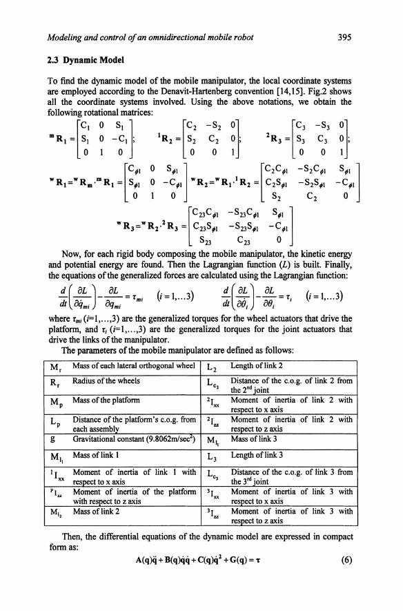
2.3 Dynamic Model
To fmd the dynamic model of the mobile manipulator, the local coordinate systems are employed according to the Denavit-Hartenberg convention [14,15]. Fig.2 shows all the coordinate systems involved. Using the above notations, we obtain the following rotational matrices:
"R, -Sd 'R, 'R,
0 8ti1 l [C2C;1 -82C;1 0 -C;1 wR 1 =wR1.1R1 = C28;1 -828;1
1 o 82 C2
[C23C;1 -823C;1 8;1 ]
WR3=WRz·lR3 = c238;t -8238;1 -C;t
823 C23 o Now, for each rigid body composing the mobile manipulator, the kinetic energy
and potential energy are found. Then the Lagrangian function (L) is built. Finally, the equations of the generalized forces are calculated using the Lagrangian function:
=Tm; (i=1, ... 3) =T; V=1, ... 3)
where Tm; (i=1, ... ,3) are the generalized torques for the wheel actuators that drive the platform, and T; (i=l, ... ,3) are the generalized torques for the joint actuators that drive the links of the manipulator.
The parameters of the mobile manipulator are defined as follows:
Mr Mass of each lateral orthogonal wheel L2 Length of link 2
Rr Radius of the wheels Lc2 Distance of the c.o.g. of link 2 from the 2nd joint
MP Mass of the platform 21xx Moment of inertia of link 2 with respect to x axis
LP Distance of the platform's c.o.g. from 21zz Moment of inertia of link 2 with each assembly respect to z axis
g Gravitational constant Mt• Mass of link 3
MI. Mass of link 1 L3 Length of link 3
I I Moment of inertia of link 1 with Lc3 Distance of the c.o.g. of link 3 from XX respect to x axis the 3'd joint
PI.,. Moment of inertia of the platform 31"" Moment of inertia of link 3 with with respect to z axis respect to x axis
M•• Mass of link 2 31zz Moment of inertia of link 3 with respect to z axis
Then, the differential equations of the dynamic model are expressed in compact form as:
A(q)q +B(q)qq +C(q)q2 +G(q) = T (6)

396 Advances in Networked Enterprises
where
[
1a1 [1
b1 ••.
1b15
] [1c1
:.·· A(q) = : . , B(q) = : . ·. : ; C(q) = ; . . ,
6al 6a6 6bl ... 6b!s 6cl ... 6c6
G(q) = [1g 2g 3g 4g 5g 6gf; q = [iimi iim2 iim3 01 82 eJ; qq = (qm!qm2 ... qm!e3 qm2qm3 ... qm2e3 qm3e/ ... qm3e3 e/82 e/83 0203 y 42 = (q;,l q;,2 q;,2 Of Oj 0} r; T = [rm/ Tm2 Tm3 T1 T2 rJr (7)
where some intermediate coefficients that simplify the final form and the parameters
iai, ibk> ici and ig(i,j=l, ... ,6andk=1, ... ,15) aredefmedintheAppendix.
3. CONTROL OF THE MOBILE MANIPULATOR
3.1 Computed Torque Control
The idea behind the computed torque control technique is to simplify the form of the system dynamics, implementing a feedback linearization of the dynamic model of the mobile manipulator [5].
Choosing a control law as T = A(q)v + B(q)qq + C(q)q2 + G(q) (8)
the dynamic model of the overall system becomes q = v where v is the "equivalent input" for the resulting dynamic system. Using a control law of the type:
.. 22* 12-v=qd- q (9)
where qd is the vector of the joint variable set-points; ..tis a strictly positive
constant; and ij = q -qd is the vector of the position error, the dynamic equation of
the error found to be: (10)
which converges to zero exponentially because of the strictly positive value of ..t. In our initial experiments, the parameters of the mobile manipulator were
assumed to be exactly known, supposing the dynamic model without uncertainties. The numerical parameters used for these experiments are shown in Table 1. They were drawn from [6]. The initial conditions of the mobile manipulator are all at zero.
Table 1- Numerical values of the mobile manipulator's parameters Mass of each lateral ortho2onal-wheel 0.5 Kg Radius of the wheels 0.0245 m Mass of the platform 30 Kg Distance between the platform's c.o.2. and each assembly 0.178 m Moment of inertia ofthe platform with respect z axis 0.9375 Kgm' Mass of link I 1.25 m Moment of inertia of the link I with resoect x axis O.OI004 Kgm' Mass of link 2 4.I7 Kg Lenl!:th of link 2 0.5 m

Modeling and control of an omnidirectional mobile robot 397
Position of the c.o.g. of link 2 along the link 2 0.25 m Moment of inertia of the link 2 with respect x axis 0.34972 Moment of inertia of the link 2 with respect z axis 0.00445 Kgm' Mass of link 3 0.83 Kg Length of link 3 0.10 m Position of the c.o.g. of link 3 the link 3 0.05 m Moment of inertia of the link 3 with respect x axis 0.00321 Kgm' Moment of inertia of the link 3 with respect z axis 0.00089 Viscous coefficient (for all rotational joints) 0.1 Nms
We shall now present two set of experimental results obtained for the case of a straight line (Fig.3-i) and a circle of 5m diameter (Fig.4-i) as trajectory for the platform's c.o.g. In both cases, the platform is assumed to have a constant angular velocity of I 0 per second with respect to the absolute coordinate system (ii) and the joint angular velocities of the manipulator were selected to be constant (iii-v). The doted line represents the set points and the solid line represents the responses of the dynamic system (angles are represented in radians and distances in meters).
u
(ii)
/ /
/' .. /
I I' ' I"
u
(v)
/ ,.;/
/ u /!'
I • • 111 • • • .JI • • • I • • • e • • 'It • • tit • • • 111 • .. II M il •• .... .... --Figure 3- Straight line trajectory of the c.o.g. with a platform rotational velocity of
1 o per second and a ramp trajectory for every manipulator joint .
(i)
.... 4 ·I t I i ,......, ........ _ ......... .....,....
(ii) / ,/
./ :/ .I"
..,. . . . . . ... ....................... ............. ....
398 Advances in Networked Enterprises
(iii} /
!· / !u / lu /
:I . .. .....
(iv) / /
// /
,I
. .. ...
!u ! ' I· •
M
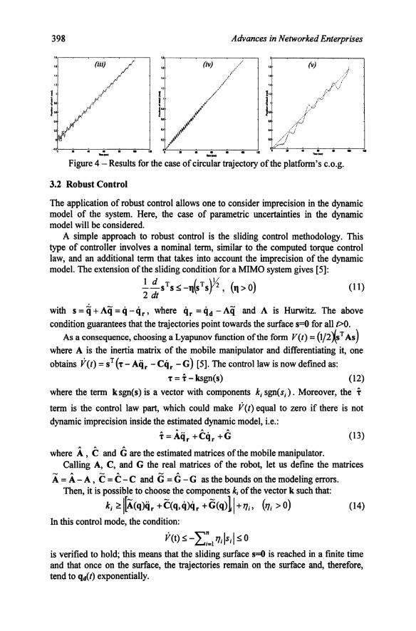
.. ... Figure 4- Results for the case of circular trajectory of the platform's c.o.g.
3.2 Robust Control
The application of robust control allows one to consider imprecision in the dynamic model of the system. Here, the case of parametric uncertainties in the dynamic model will be considered.
A simple approach to robust control is the sliding control methodology. This type of controller involves a nomiilal term, similar to the computed torque control law, and an additional term that takes into account the imprecision of the dynamic model. The extension of the sliding condition for a MIMO system gives [5]:
(tt>O) (11) 2 dt
with s = q + Aq = q - cir , where cir = qd - Aq and A is Hurwitz. The above condition guarantees that the trajectories point towards the surface s=O for all t>O.
As a consequence, choosing a Lyapunov function ofthe form V(t) = (l/2XsT As) where A is the inertia matrix of the mobile manipulator and differentiating it, one obtains V(t) = sT ('T- Aqr -Cqr -G) [5]. The control law is now defined as:
'T = T- ksgn(s) (12)
where the term ksgn(s) is a vector with components k; sgn(s;). Moreover, the T
term is the control law part, which could make V(t) equal to zero if there is not dynamic imprecision inside the estimated dynamic model, i.e.:
(13)
where A , C and G are the estimated matrices of the mobile manipulator. Calling A, C, and G the real matrices of the robot, let us define the matrices
A = A- A , C = C-C and G = G - G as the bounds on the modeling errors. Then, it is possible to choose the components k; of the vector k such that:
k; ::::I[A.<q>iir +C(q,ci>cir +G<q>11+7];. (71; >o) (14)
In this control mode, the condition:
V(t) S-L;=17];1s;l s 0
is verified to hold; this means that the sliding surface s=O is reached in a finite time and that once on the surface, the trajectories remain on the surface and, therefore, tend to qd(t) exponentially.

Modeling and control of an omnidirectional mobile robot 399
For the experiments, we suppose that the length of the links and the distance between the c.o.g. of the platfonn and the wheel-assemblies is known exactly. For all the other parameters, we consider a bounded range of possible values for every parameter choosing the "mean" values of these ranges as the estimated parameters and the "extreme" values of the ranges as the real parameters. We use the values of the parameters used for the computed torque control design as the estimated parameters of the robot, and the values presented in Table 2 as the real parameters of the robot. The results of Fig.5 and Fig.6 are obtained under the same conditions for the trajectories as in both cases of the computed torque control.
Table 2- Real numerical va ues of the mobile manipulator parameters Mass of each lateral orthogonal-wheel 0.525 Kg (5% more) Radius of the wheels 0.0245 m (exact) Mass of the platform 33 Kg (10% more) Distance between the platform's c.o.g. and each assembly 0.178 m (exact) Moment of inertia of the platform with respect z axis 0.984375 (5% more) Mass of link 1 1.375 m (10% more) Moment of inertia of the link 1 with respect x axis 0.010542 Kgmz (5% more) Mass of link 2 5.421 Kg (30% more) Length of link 2 0.5 m (exact) Position of the c.o.g. of link 2 along the link 2 0.25 m l_exact) Moment of inertia of the link 2 with respect x axis 0.367206 Kgmz (5% more) Moment of inertia of the link 2 with respect z axis 0.0046725 Kgmz (5% more) Mass oflink 3 1.0790 Kg (30% morel Length oflink 3 0.10 m (exact) Position of the c.o.g. oflink 3 along the link 3 0.05 m (exact) Moment of inertia of the link 3 with respect x axis 0.0033705 Kgmz (5% more) Moment of inertia of the link 3 with respect z axis 0.0009345 (5% more) Viscous coefficient (for all rotational joints) 0.13 Nms (30% more) .. .. {i)
(v)
/ /
... 1 2 J ... 1 , ••• ..... f 2 t 4 fIJI lw---: I - ..... Figure 5- Robust control results- Straight trajectory for the c.o.g. of the platfonn

400
(i)
·• ( \
u "'.a -"'**'" ..... ,_ ..........
Advances in Networked Enterprises
(ii)
• a • • • • ... .......... -................. _.,...
Figure 6- Robust control results- Circular trajectory for the platform's c.o.g.
4. CONCLUSIONS
The study of an omnidirectional mobile manipulator was presented in this paper. After deriving the kinematic and dynamic models of the 6-dof robot, the control problem was considered. Two types of controllers were used and their experimental results were demonstrated. At first, the results obtained using the computed torque controller were presented, showing the exponential stability of the global system. Then, the presence of some imprecision on the numerical parameters of the dynamic model was assumed.
The results of the simulation showed that the robust controller is able to control the mobile manipulator despite the presence of parameter imprecision. Actually, the performance of the robust control is significantly better than that of the computed torque control (comparing, for example, the experimental results shown in Fig.3 with those shown in Fig.S, the superior performance of the robust control is evident).
The negative aspect of the robust controller is the chattering produced in the region neighboring with the set points (for example, in Figures S[(iii),(iv)] and 6[(iii),(iv)] the chattering is very evident). This is because of the presence of a discontinuous term inside the robust control law. It is necessary to avoid this phenomenon because the high frequency components present in the control law could excite some unmodeled dynamics. To this end, a bounded time-varying region that includes the sliding surface has been proposed (in [5] for example). Inside this region the control law has a smooth behavior, while outside the region the control law continues to be as in the previous control law used for the robust control.

Modeling and control of an omnidirectional mobile robot 401
5. REFERENCES l. Hootsmanns NAM, Dubowski S. The Motion Control of Manipulators on Mobile Vehicles. Proc
IEEE Inti Conf on Robotics and Automation (ICRA'91); 2336-2341. 2. Minami M, Fujiwara N, Tsuge H. Position and Orientation Control of Manipulator Mounted on
Autonomous mobile Robot. J of the Robotics Society of Japan 1993; 1: 156-164. 3. Pin FG, Culioli JC, Reister DB. Using Minimax Approaches to Plan Optimal Task Commutation
Configurations for Combined Mobile Platform-Manipulator Systems. IEEE Trans R&A 1994; 1. 4. Pin FG, Killough SM. A New Family of Omnidirectional and Holonomic Wheeled Platforms for
Mobile Robots. IEEE Transactions on Robotics and Automation 1994; 4:480-489. S. Yamamoto Y, Yun X. Modeling and Compensation of the Dynamic Interaction of a Mobile
Manipulator. Proc IEEE Inti Confon Robotics and Automation 1994; 184-2192. 6. Yamamoto Y, Yun X. Coordinating Locomotion and Manipulation of Manipulator. IEEE Trans
Automatic Control 1994; 6: 1326-1332. 7. Khatib 0, Yokoi K, Chang K, Ruspini D, Holmberg R, Casal A. Coordination and Decentralized
Cooperation of Multiple Mobile Manipulator. J Robotic Systems 1996; 11: 755-764. 8. Lee JK, Cho HS. Mobile Manipulator Motion Planning for Multiple Tasks Using Global
Optimization Approach. J Intell and Robotic Systems 1997; 169-190. 9. Minami M, Asakura T, Fujiwara N, Kanbara K. Effects of Inverse Dynamics Compensation for
Nonholonomic Mobile Manipulators. J of the Robotics Society of Japan 1997; 2: 216-222. 10. Chong NY, Yokoi K, Oh SR, Tanie K. Position Control of Collision-Tolerant Passive Mobile
Manipulator with Base Suspension Characteristics. Proc IEEE Inti Conf on Robotics and Automation (ICRA'97); 594-599.
11. Seraji H. A Unified Approach to Motion Control of Mobile Manipulators. Inti J of Robotics Research 1998; 2: 107-118.
12. Watanabe K, Shiraishi Y, Tang J, Fukuda T, Tzafestas SO. Autonomous Control for an Omnidirectional Mobile Robot with Feedback Control System. Advances in Intelligent Autonomous Systems 1999, Athens, Kluwer Academic Publishers, ed. Tzafestas SO, 13: 289-308.
13. Watanabe K, Sato K, Izumi K, Kunitake Y. Analysis and Control for an Omnidirectional Mobile Manipulator. J oflntell and Robotic Systems 2000; 1-2: 3-20.
14. Fu KS, Gonzales RC, Lee CSG. "Robotics: Control, Sensing, Vision and Intelligence". McGraw-Hill, New York, 1987.
15. Megahed SM. "Principles of Robot Modelling and Simulation". John Wiley Ltd, 1993. 16. Slotine J, Li W, "Applied Nonlinear Control". Prentice-Hall, 1991. 17. Tzafestas SO, Raibert M, Tzafestas CS. Robust Sliding Mode Control Applied to a S-link Biped
Robot. J lntell and Robotic Systems 1996; 1: 67-133. 18. Tzafestas SO, Krikochoritis TE, Tzafestas CS. Robust Sliding Mode Control of9-Link Biped Robot
Walking. J Intell and Robotic Systems 1997; 2-4: 375-402. 19. Chung JH, Velinsky SA. Robust Interaction Control of a Mobile Manipulator- Dynamic Model
Based Coordination. J Intell and Robotic Systems 2000 (to appear).
Appendix _ I 2. _ 2 2 I p 2. 2 2 I p 2. 2 2 I 1 2.
A, --M,R., Ap --MPR, I .. R., Bp = --MpRr I .. R,, A1 =-M11R, I .. R,, 2 9 IBLp 9 9LP 9 IBLP
l1 2 2 1 1 2 1 1 I 1 2 l2 I 2 B1 Ixx;G1 =--9 MI1R, IxxR,;DI =-R, lxx;Az =-MI2 ;B2 =-M12L02 -t- I .. ;G2 =-M12 L02 ;
9LP 3Lp 2 2 2 2
12 I • 4 2 • 2 2 • 2 • 2 2 D2 l I .. ;E2 =3M12L02 R,;F2 =M12 ·g·L02 ;Az =9R,A2;G2 = 91; R,C2;G12 = lLp R,C2;Dz = 91; R,D2;
o;2 =-2-R,D2; AJ =.!..Mil; BJ :.!..31 .. ; GJ :.!..3I,.,.;DJ =Mil . g;pl = - 2-R,C2; Pz = 2C2; PJ = - 2-R,Dz; 3LP 2 2 2 3LP 3LP
p4 = 2D2;y1 = A3;Y2 = L!1A3;y4 =2A3LzL01 ;ys = B3;y, = C3;y7 = D3;E3
v=-2y3si"281 +283)-2y4cos81si"61 co=-y3si"281 +283)-y2si"281)-y4si"281 w=-y3 si"281 + 283)-y4 cos81si"61 p=-2y2si"281)-2y3 si"281 +283)- 2y4si"281
1J=2y2 col?- 61 + 2y3 coi-(61 +63)+2y4 cos81 +63)+ 2y6; Intermediate coefficients

1a1 =2(A, +A
, +A1 +A
;)+o; +G;(C
2) 2 +
4q
+!.R
:y1
+E:J)c2
+.fiC
1 ); 1a1 =
B,+
G1 -A
; +
9L,
9 JL
,
• 0
• c ,
.&.
4 ,
2R, I(
E )c
., ,
• •
• ,
R'
4 ,
+D
z+
:z( 2
) +
9 1.!'1
-9R
r'Yl+
JL,
E:z+
3 2+
f:JCn.P
l; a,=
B,+
Ga-A
2+
D2
+G
2 (C1 )
+ ..&._K
E, + E,)c, + F
,c,);-s, + .J)c,); '•• = o, + o;, + o;,(c,>
' + E
,)c, + F,c,);s, +
./JC,);
JL,
JL,
• .. = -{(E, + E
,)s, + F,S
,);-c, + .fis,); • .. = -F,S
,(-C1 + ./Js,
1b1 =
1b1 = 0; 1b
3 =
+ E,)c
2 + F,C
,):C1 -
./JS,); JL
,
+E
3 )s, + F,S,);S, +./JC
1 ); 1b5
+./JC
1 ); 1b6 =0;
9L,
JL,
9L,
JL,
1 )c
):; 1
• .
( )
R2
2R ((E
)s, \,
1 R
2 2R
b
7=
3 L, E
2+
E3
2+
f:JCn
1; b
1=
-G2 am
282
'b,.
[(E, + E,)c, + F
,c,);c, + 1b11 =
-<i;ain
(2B
,)+4
•• ..&._[(E, + E
,)s, + F,S
,):s,- ./3c1 ); p
1bn
=4
v+
-=-3 RL
F,S
,(S,-
.fiC1 );
1bll = -G
;2 ain(281 )+ ..&
._ __
z((E, + E3 )
;2 + F,S,);S, + 9L
, ,
JL,
1b14 =
Ji'-v-
2 F,S
,(S, +
1b15 = -2 F
,C,(-c
1 + ./JS,); 1c4 =
((E2 + E
,)c, + F,C13 ):C
1-
./JS1 );
p 1
1c,=1t,=
1c3 =0; 11=0; 1cs = -((E
2 + E3 )c
2 + F,C
,\-c1 + ./JS,); '•• =
-F,C
,(-C1 + .fiS,);
2a1 =B
, +G
1 -A; +
D; +
G;(C
2 ) 2 +4
11
-,!YtR
: +2.!.t...((E2 +
E3 )c
2 +
2a1 =2(A
, +A
, +A
1 +A
;)+ o; +
9
L,
9 JL
,
G'(C
)'.&_
B
R'
)c .J
3,'
• •
• 'R
' 4
'
1 2
rTI+
JL,
Ez+
E3
2
+
13 S
t-C
1 ); a
,=B
,+G
,-A2
+0
2+
G2 (C
2 )
-JRL, ((E
, + E,)c, +
+ ./JC1 ); 1a
4 = D1 + o;, + o;,(C
1) 1 +
+ ((E, + E,)c, + F
,C,);S
, -./JC
1 );
p
• .. =((E, + E
3);, + F,S,};C
1 + ./JS,); ' .. = F
,S,(C
1 + ./JS1 ); 1b
1 =1b
1 =0; 1b
3 + E
,)c, + F,C
,):;1 ; 3L,
J •.
( )
R'
2R I!
); )s
J R
' 2R
J
b,. = -G:z am
282 +
JL
; E
2 + E
3 2 +
1 ;
b5 =
b, =
0;
1b, =
=3 2LR ((E, +E
,)c, + F,c,);C
1 + ./JS,); 1b
1 = -G;ain(2B
1 )+ + E
,);, + F3 S,);S
,-,
9L,
JL,
I R
2 2R
r.::
J R
I( '
r.. •
R2
b, = -=-
9 L2 •i3C
1 ); b10 =-"'-JL
E2 + E
3 )c2 + + •3S,); 'b
u = -G
2 ain(281 )+ .::r-•+
,
, ,
9L,
•Ji'-((E, + E
,)s, + F,S
,);S, + ./JC
1 ); 1bn
=4
v+
.!t._F,S
,(S, + ./JC
1 ); 1bu
= -G;2 oin(281 )+
..&._ _
_
p 9L
, JL
, JL
,
-z((E, + E
,)s, + F,S,);S, -./JC
1 ); 1b14 = ..&
._v- 2 F,S
,(S, -
./JC1 ); 1b
15 = 2 F,C
,(C1 + .fis,); 1c
1 ='c,=
'c3 = 0;
JL,
2 '•• =[(E
, + E,)c, + F
,c,);c, + .fis,); '•• = [(E, + E,)c, + F
,c,);c, + .J3s,); •._ =
F,C
,(C1 + .J3s,);
'a =O;
3•t :8, +
01 -A
; +D
; +G
;(Czl
+..&
..((E2 +
E3
):1 +
.J3C1 ); 3a, ==B
, +0
1 -A; +
0; +
G;(C
2 ) 2 + 9L
, 9
3LP
.&
4 ,
R K
1:
l .Jj,
' I.
•) •
• ,
R'
8 ,
+ 9 L! 11-9y
1 R,
E2 +E
3 2 +
F3 C
23 -S
1 -3C
1 ); a3 :::2\A
, +A
, +A
1 +A
2 +0
2 +G
2 (C2
)
--'=34LR KEz +
El):::l +
Flc23lit; J•• ==D
, +0
;2 +
G;2(C
2)l +...&
..q-2KE
z +E
J):::l Jas ::-2({Ez
+F
JSzJ):t;
, 3L
,
1-.s ::-2F3 8z:JC1 ;
1b1 =
'b2 =
0; 3b
, ==_&.K
E1 +
E3 ):2 +F1C
23 l-Ct- J3St);
3b4 ::--G;sin(28J)+
.!i_J.L +
3L
, 9L
!
+-"'-3 Rl
((E2 +E
3 )s, +F
,S,l-S
t 3b5
3b6 •0; 3b7 =.&..((E
, + E3 1:, +F
3 e,t-e
, +.fiS.); p
9L,
3L,
3L,
3b1
+E3 )s, +F
3 S,ls,
3b,
+J3e
1 );
, 4R
(( 1:
):: , • . (
) R
1 4R k
>,
R1
4R
hte
=-3
f,-E
1+
E3
2+
F3 C
23 1 ;
b11
:::--G1
sm2
82
3btl =--G
;2sin.(28J)+...:.:.L..
3 Rl J.L+4{(E2
3ht4 3b15
:::--41)C23 C
1 ; 3e1 =='c::z"" 3e3 =O;
P 3L
, 3
3C4 :::-2({E:z +f3C
23):1; 3es =
-2k
E2 +
E3 )c
2 +I)C
23 ):,; 31:::0;
4•t•D, +
llt(Cz) 1 +P1 + ...&
..q+kE
z + E1)c1
+ Jlc,); 41•1
'""0. +J',(C
z) 1 +P1 + _&_'l+
kEz +
E1)c1 +
-.J1c,);
JL,
JL,
•., •Dt +
Pt(C
z) 1 +P1 + E
1)c1 •a,. .. 29t
+P
t 4As'"" 4
"' •O
;
41tt•-.=.:.t.3 2R
K
Ez + E1)c1 +
4ltz .. ..&...K
Ez + E
,)cl + + .fis,); 41t3
-0; 4lt4 ..
41t5 • ..&..v; L
, JL
, JL
, JL
,
•e., aa-...:.:L.
3 R
[(El + E
1)c1 +F
lclll-e
, + J]s_); 411t,. •0", 4b1 •-t'Jsin(28z)+..&
_fl; 41t, • ..&...v; 41t11 ,.Q-, 41t11 "'-PJsin(lB
:z)+..&._fl;
L,
JL,
JL,
JL,
41tu ·ii'-v. 41tu •-P:zsin(l8:z)+J.L; ....... v; ... "
•0; •c, s-ii'-K
E:z + E
,)cl +F
]Clllc
.-/is,); •c ..... •es .. •fr.
p p
4ez ..,_...:.:L.]R kE1 +
E1 )c1 + I)C
lllc1 +JlS
,); 41c3 .. 2.!L
kE
1 + E3 )c
1 + F1 Cll)::1 ;
4&•0
; L
, JL
, 4
+I)S
uk-G +
./is,); 1•
J --2
(E2
+F,Sn):;: 1•••0;
+Tt
•-. •lrJ +r.C
, + 21'1: '•• •-F,sn(-C
• + .fis..t.
'•s•-F,sn
(-G.-
.fiS.); '•J •-lF,S
nG: •., •0;
+T4C3 +21',: '-. •l(r, +
rs}
+F,SnkS. -.fiG); ..
... , .. '11,:•0; OM.;
3Lp 9'-;
3L,
3Lp
s R
1 R
c.
R
R
.. +
i)SnJ,"'' +-v-.tCI);
'·'11
.,•0;
11t:tt• 1lttl• 11tu..Sit14 •0; 11tu•-2li!>J;
4 R
,
2R1
R
r:;-_ ,
2R
2R2
R
r:;_
•,--9t.; 'f+
2Jf;F,S
uS..;
112 --v-.J\.;1};
'•··'•,-a: 'II, '11, • -rx;.-; ...... .., • O; '••• • -rx;,;
• O; 11
• +
+
L., y.,Cu:
'1• L., r.,C
n:
''••-..!\--+.!t...(£1 +E
1 ), +F,S
n}S,. +
Jic1 ); 1c1
•-4-+
.!t...(E1
+F,sn):s1 -.fiC
1 'r, +F,Sn)s.; 1c4
•-co;
ox.; ,
s ,
R1
R
r::-,
R1
R
r:: R
2 R
,,.0;
'e,•-.-. 'es•r/!>s: 6