Modeling and Analysis of Truck Mounted Concrete Pump Boom...
11
Research Article Modeling and Analysis of Truck Mounted Concrete Pump Boom by Virtual Prototyping Wu Ren, 1,2 Zhongwei Li, 1 Yanping Bi, 1 Shan Zhao, 1 Bo Peng, 3 and Liming Zhou 1 1 School of Biomedical Engineering, Xinxiang Medical University, Xinxiang, Henan 453003, China 2 State Key Laboratory for High Performance Complex Manufacturing, Central South University, Changsha, Hunan 410083, China 3 Hunan Special Equipment Inspection and Testing Research Institute, Zhangjiajie Branch, Zhangjiajie, Hunan 427000, China Correspondence should be addressed to Wu Ren; [email protected] Received 4 February 2017; Accepted 7 May 2017; Published 14 June 2017 Academic Editor: Shahram Payandeh Copyright © 2017 Wu Ren et al. is is an open access article distributed under the Creative Commons Attribution License, which permits unrestricted use, distribution, and reproduction in any medium, provided the original work is properly cited. By far there is lack of research on different working conditions between rigid and flexible dynamics of truck mounted concrete pump booms. First a 3D model has been established by using virtual prototyping technology of a 37 m long boom in Pro/Engineering soſtware. en the rigid body simulation model has been built. Next modal superimposition method is adopted to change the 4 rigid body booms into flexible ones. Kinematics law and dynamic characteristics of 4 common working conditions had been studied then. Next tip displacement and the first boom hydraulic cylinder force of the 4 working conditions between rigid and flexible models have been researched. Furthermore the first natural frequencies of the structure have been calculated. e results show that the frequency of the horizontal condition has the lowest of all and the roof condition has the largest of all. Besides the cylinder forces of the flexible model are larger than the corresponding rigid ones because of the flexible boom vibration. Finally an experiment has been done on a boom test rig which proved that the established simulation model is reasonable and the frequency results are correct. All of these provide design reference to mechanical manipulator as well as reducing product development cost of such mechanism. 1. Introduction In recently years, CAD/CAE/CAM/PDM has been further developed including VP (virtual prototype) and PLM (prod- uct life-cycle manager) technology [1]. VPD (virtual prod- uct development) originated from the Boeing Company in 1990. e use of all digital paperless design made the cost decrease by 25% and manufacture cycle reduce by 50%. is application technology was called VP (virtual prototyping technology). Virtual prototyping relies on the technology of CAX (such as CAD, CAE, and CAM), DFX (such as design for assembly), and DFM (design for manufacture). Virtual product development has 3 main features: the first one is digitization [2–5]. Next is product life cycle. is is supported by CAD/CAE/CAM/PDM. e last one is network coordination. e development of modern Internet technology makes the network coordination become real. Until now more and more fields are using virtual pro- totyping technology like vehicle test, train system design, robot control, bridge construction, flexibility manufacturing, hazard identification, and so on. e use of this technology will greatly reduce the development costs and time [6–8]. e relationship between virtual prototyping and traditional CAD/CAE/CAM is shown in Figure 1. e scientific and innovative contribution of the paper is the establishment of a truck mounted concrete pump boom model considering the boom flexibility and hydraulic actuator equivalent stiffness. In this paper flexible multibody theory has been used to get the dynamics characteristics of different working conditions. us the spray control and motion accuracy can be got during the working process. In the previous research the oil elasticity modulus was not considered in the calculating of hydraulic cylinder stiffness. So the flexibility of the cylinder is not accurate. In this paper the cylinder stiffness and boom flexibility are both considered. us the accurate boom kinematic and dynamics response could be obtained. e boom model is made up of multisection operating booms, connecting links, hydraulic Hindawi Journal of Robotics Volume 2017, Article ID 9182143, 10 pages https://doi.org/10.1155/2017/9182143
Transcript of Modeling and Analysis of Truck Mounted Concrete Pump Boom...

Research ArticleModeling and Analysis of Truck Mounted ConcretePump Boom by Virtual Prototyping
Wu Ren12 Zhongwei Li1 Yanping Bi1 Shan Zhao1 Bo Peng3 and Liming Zhou1
1School of Biomedical Engineering Xinxiang Medical University Xinxiang Henan 453003 China2State Key Laboratory for High Performance Complex Manufacturing Central South University Changsha Hunan 410083 China3Hunan Special Equipment Inspection and Testing Research Institute Zhangjiajie Branch Zhangjiajie Hunan 427000 China
Correspondence should be addressed to Wu Ren renwu88126com
Received 4 February 2017 Accepted 7 May 2017 Published 14 June 2017
Academic Editor Shahram Payandeh
Copyright copy 2017 Wu Ren et al This is an open access article distributed under the Creative Commons Attribution License whichpermits unrestricted use distribution and reproduction in any medium provided the original work is properly cited
By far there is lack of research on different working conditions between rigid and flexible dynamics of truckmounted concrete pumpbooms First a 3D model has been established by using virtual prototyping technology of a 37 m long boom in ProEngineeringsoftware Then the rigid body simulation model has been built Next modal superimposition method is adopted to change the4 rigid body booms into flexible ones Kinematics law and dynamic characteristics of 4 common working conditions had beenstudied then Next tip displacement and the first boom hydraulic cylinder force of the 4 working conditions between rigid andflexible models have been researched Furthermore the first natural frequencies of the structure have been calculated The resultsshow that the frequency of the horizontal condition has the lowest of all and the roof condition has the largest of all Besides thecylinder forces of the flexible model are larger than the corresponding rigid ones because of the flexible boom vibration Finally anexperiment has been done on a boom test rig which proved that the established simulation model is reasonable and the frequencyresults are correct All of these provide design reference to mechanical manipulator as well as reducing product development costof such mechanism
1 Introduction
In recently years CADCAECAMPDM has been furtherdeveloped including VP (virtual prototype) and PLM (prod-uct life-cycle manager) technology [1] VPD (virtual prod-uct development) originated from the Boeing Company in1990 The use of all digital paperless design made the costdecrease by 25 and manufacture cycle reduce by 50 Thisapplication technology was called VP (virtual prototypingtechnology) Virtual prototyping relies on the technologyof CAX (such as CAD CAE and CAM) DFX (such asdesign for assembly) and DFM (design for manufacture)Virtual product development has 3 main features the firstone is digitization [2ndash5] Next is product life cycle Thisis supported by CADCAECAMPDM The last one isnetwork coordination The development of modern Internettechnology makes the network coordination become realUntil now more and more fields are using virtual pro-totyping technology like vehicle test train system design
robot control bridge construction flexibility manufacturinghazard identification and so on The use of this technologywill greatly reduce the development costs and time [6ndash8]The relationship between virtual prototyping and traditionalCADCAECAM is shown in Figure 1
The scientific and innovative contribution of the paperis the establishment of a truck mounted concrete pumpboom model considering the boom flexibility and hydraulicactuator equivalent stiffness In this paper flexible multibodytheory has been used to get the dynamics characteristicsof different working conditions Thus the spray control andmotion accuracy can be got during the working processIn the previous research the oil elasticity modulus was notconsidered in the calculating of hydraulic cylinder stiffnessSo the flexibility of the cylinder is not accurate In thispaper the cylinder stiffness and boom flexibility are bothconsideredThus the accurate boom kinematic and dynamicsresponse could be obtained The boom model is made upof multisection operating booms connecting links hydraulic
HindawiJournal of RoboticsVolume 2017 Article ID 9182143 10 pageshttpsdoiorg10115520179182143
2 Journal of Robotics
System oriented virtual prototyping technology
Components oriented CADCAECAM technology
Design Analysis Production
Product data management system (PDM)product lifecycle management system (PLM)
Virtual physical prototype Virtual prototypingtechnology Virtual product
CAD CAMCAE
mdashmdash
Figure 1 Virtual prototyping and traditional CADCAECAM comparison
actuator cylinders and joints Usually the boom can besimplified as a slim beam and the load is mainly coming fromself-weight and pump impactThus the boom system stiffnessmust be large and the self-weight should be light Frequentlyboom system dynamics experiments will increase cost andwaste time which can not satisfy production demand Butvirtual prototyping technology can solve this problem andreduce the product development cycle [9 10]
Up to now Slepniov et al studied production innovationand service networks of companies all over the world [1]They proposed the widening geographical and cognitivegaps between the networks becoming strategically impor-tant method in production research Jiang et al studiedconcrete pump outriggerrsquos effect on the safety and stabilityof the system The relationship between pipe length andoutrigger area is obtained then [11] Ling et al did thesimulation of a mobile pump boom motion process Themost dangerous working conditions of cylinders had beenstudied which offered theoretical basis for the optimizationdesign of the hydraulic cylinders [12] Wang et al analyzedpouring process of a mobile concrete pump boom Nextthey proposed intelligent pouring program of it In theend the trajectory plan and virtual environments work hadbeen simulated [13 14] Guo et al established the dynamicequation of flexible booms according to robot theory andlanguage equation which is help for the automatic pouring[15] Chen and Sun studied the structural optimization ofconcrete pump displacing boom system by using BP neuralnetwork finite element and genetic algorithms [16] Zhanget al established a truck mounted concrete pump simulationmodel in ADAMS software and studied the force betweenthe cylinder and link joints which provide design guide forsuch mechanism [17] Guo et al improved the automationpour process by using optimal control method of a mobileconcrete pump boom [18] Jiang built a concrete pump boomvirtual prototyping model and carried out the simulation bymultibody dynamics and finite element method [19] Dai etal used PD control method into concrete pump boom driveBy their study the boom can move in desired angle [20]Finally they made the boom move with expected rotationangle and tip trajectory Zhang et al did control to a flexible
boom driven by hydraulic cylinder and had researched thevibration depression of the system [21 22] The safety anddiagnostic applied to concrete displacing boom are done byAmbrosio et al Then Resta et al established a 1 3 reducedmodel of a mobile concrete pump Vibrations suppressionfeedforward and feedback actions disturbance estimator andmodal control were researched Modal space control methodis used to reduce the tip vibration and trajectory control[23ndash28] Lenord et al studied a flexible hydraulic mobileconcrete pump truck Linear and nonlinear models weresimulated by damping optimization [29] In the end a linearmodel was used to substitute the nonlinear model in orderto reduced computational cost Sun et al proposed a closed-loop monitoring and open-loop control method to suppressthe boom vibration [30]
Due to the fact that vibration is very important in thedynamics and kinematics analysis of the concrete pumpboom a rigid-flexible method is adopted in this paper toestablish an accurate model of the boom It is organized asfollows Firstly modal superimpositionmethod is introducedand used Then rigid and flexible body virtual prototypingmodels of a truck mounted concrete pump boom have beenestablished Next the tip displacement and force comparisonof the twomodels in different working conditions are studiedThen natural frequency of the flexible model has beencalculated and an experiment has been done on a boom testrig In the end the conclusion has been discussed
2 Modal Superimposition Method
The multiple degree-of-freedom system with proportionaldamping motion equation is as follows
[119872] + [119862] + [119870] 119909 = 119891 (119905) (1)
In (1)
[119862] = 120572 [119872] + 120573 [119870] (2)
Here in (2)120572 and120573 are proportional constant [119862] is dampingmatrix and [119872] and [119870] are the mass matrix and stiffness
Journal of Robotics 3
matrix respectively represents vector and [] representsmatrix By the coordinate transformation (3) is obtained
119909 = 119873sum119903=1
119902119903 120593119903 (3)
In (3) 120593119903 is the 119903-order mode shapes By replacing (3) with(1)
[119872]( 119873sum119903=1
119902119903 120593119903) + [119862]( 119873sum119903=1
119902119903 120593119903)
+ [119870]( 119873sum119903=1
119902119903 120593119903) = 119891 (119905) (4)
Then (4) premultiplied 120593119904119879
120593119904119879 [119872] 120593119903 = 0 119903 = 119904119898119904 119903 = 119904
120593119904119879 [119870] 120593119903 = 0 119903 = 119904119896119904 119903 = 119904
(5)
The following equation can be got
120593119904119879 [119862] 120593119903 = 120572 120593119904119879 [119872] 120593119903 + 120573 120593119904119879 [119870] 120593119903=
0 119903 = 119904120572119898119904 + 120573119896119904 = 119888119904 119903 = 119904
(6)
Here 119898119904 119896119904 119888119904 are the 119904-order modal mass modal stiffnessand modal damping coefficient Next (7) can be obtained
119898119904 119902119904 + 119888119904 119902119904 + 119896119904119902119904 = 120593119904119879 119891 (119905) (7)
In (7) 119902119904 is the 119904-order modal coordinates Assuming that119891(119905) = 119865119890119895120596119905 and 119902119904 = 119876119904119890119895120596119905 by replacing them in (7)we can get
(minus1205962119898119904 + 119895120596119888119904 + 119896119904)119876119904119890119895120596119905 = 120593119904119879 119865 119890119895120596119905 (8)
119876119904 = 120593119904119879 119865minus1205962119898119904 + 119895120596119888119904 + 119896119904 (9)
i
X
Y
Z
Si
S0i
ri
ui
rZ
998400
Y998400
X998400
Figure 2 Flexible body coordinate system
In (8) and (9) 119876119904 modal coordinates vector Next thedisplacement response can be written as
119909 =
11988311198832119883119873
119890119895120596119905 = 119873sum
119903=1
119902119903 120593119903 = 119873sum119903=1
119876119903 120593119903 119890119895120596119905
119883 =
11988311198832119883119873
= 119873sum119903=1
119876119903 120593119903 = 119873sum119903=1
120593119903119879 119865 120593119903minus1205962119898119903 + 119895120596119888119903 + 119896119903
= 119873sum119903=1
120593119903 120593119903119879minus1205962119898119903 + 119895120596119888119903 + 119896119903 119865
(10)
Modal superimposition method is based on FMBD(finite element multibody dynamics) and obtains flexiblebody dynamic stress strain and deformation through finiteelement analysis Its calculation speed is fast and can calculatelarge-scale flexible bodies So it is suitable for the flexibilityanalysis of construction machinery A point 119894 on the flexiblebodyrsquos three-dimensional coordinate can expressed as inFigure 2
r119894 = r + AS119894119899 = r + A (S0119894 119899 + u119894119899) (11)
In (11) A is the direction cosine matrix S0119894 is the point 119894not deformed vector u119894 is the relative deformation and 119894 isthe translational and rotational modal matrix as shown in
Ψ119894 = [Ψ119894119879119905 Ψ119894119879119903 ] (12)
The modal coordinate of u119894 is shown as
u1015840119894 = Ψ1198941015840119905 a (13)
4 Journal of Robotics
Figure 3 Boom system CADmodel
Figure 4 Boom system rigid model
In (13) a is the generalized coordinates of deformationfrom (11) and (13) the following equation can be got
r119894 = r + A(S0119894 1015840 +Ψ1198941015840119905 a) (14)
The displacement of the flexible body is shown as (15)According to modal informationΨ the corresponding veloc-ity and acceleration equation of the flexible body can beobtained either
[u] = sum119886119894 [120593]119894 (15)
In (15) [u] is the sum of all nodes displacement 119886119894 is themodal factor [120593]119894 is the component modalThe flexible bodydeformation can be got by adding the nodes displacement
The velocity and acceleration of point 119894 can be obtainedby derivation for (14) which is shown in
r119894 = r + A(S0119894 1015840 +Ψ1198941199051015840a) + AΨ1198941199051015840a
r119894 = r + A(S0119894 1015840 +Ψ1198941199051015840a) + 2AΨ1198941199051015840a + AΨ1198941199051015840a
(16)
3 Truck Mounted ConcretePump Boom Modeling by VirtualPrototyping Technology
The established 3Dmodel of a truckmounted concrete pumpboom is shown in Figure 3The system is built up by 4 boomsseveral links hydraulic actuators joints and other compo-nents
After importing the CADmodel into RecurDyn softwarethe virtual prototyping model with appropriate constraintsis obtained too RecurDyn is multibody system software ofFunctionBay Inc It is an innovative Multibody Dynamicsoffering multibody dynamic capabilities with an integratedpowerful FEM extension With the finite element methodcombined with MFBD (Multiflexible Body Dynamics) themechanical system simulation can provide more and moreprecise dynamic motion results including stress analysis forengineersThe flexible body contacts and nonlinear deforma-tions can be solved in it too So it is very useful in dealing withthe long flexible boom here The built rigid model is shownas Figure 4 Due to the fact that the booms are flexible large-scale motion components the flexible influence should not
Rigid linkageFlexible boom Revolute joint
Translational joint
Figure 5 Flexible multibody boom topology sketch
Figure 6 The first boom modal reduction flexible body
Table 1 Parameters of boom system
Component NumberFlexible body Boom 4Rigid body Linkage 14Joint Bearing linkage boom 21Translational joint Hydraulic cylinder piston 4Spring damper Hydraulic cylinder 4
Table 2 Main parameters of each boom
Boom 1 2 3 4Length (mm) 3750 2830 2870 3200Mass (kg) 88 38 32 18
be neglected Then a flexible body truck mounted concretepump boom model is established as shown in Figure 5 Init the four booms are modal flexible bodies calculated byfinite element software ANSYS The first boom flexible bodyis shown in Figure 6 The other three booms are similar tothe first one By importing them into RecurDyn the concretepump boom flexible model has been built with constraintsconsistent with rigid body model The control scheme of thelarge scale is used with PID regulator And the model param-eters are as in Table 1 The element mass and length are inTable 2
4 Simulation and Experiment
41 Simulation Parameters The general working conditionsof concrete pump boom are horizontal condition ground
Journal of Robotics 5
Figure 7 Ground condition
Figure 8 Wall condition
Table 3 Each boom angle of working posture
Posture Boom 1 Boom 2 Boom 3 Boom 4Horizontal 0∘ 0∘ 0∘ 0∘
Ground 75∘ 15∘ minus15∘ minus75∘Wall 75∘ 45∘ 0∘ minus45∘Roof 75∘ 75∘ 45∘ minus45∘
condition wall condition and roof condition The first con-dition is simulating the long distance Because this conditionis themost dangerous working condition the stress value andflexible effect are the largest of all Next the second conditionis used in the groundworking process And the third workingcondition is used in the wet concrete pumping of lower floorsThe last simulation is about the upper floors So these foursimulations are typical working conditions of concrete pumpboom In the built model the tip displacements and the firsthydraulic cylinder force are studied The four simulationpostures angles of the twomodels are shown in Figures 4 7 8and 9 Table 3 is the posture angle of each working condition
In order to get the truck mounted concrete pump boomkinematic rule and vibration characteristic the motion sim-ulation results of the above working conditions are studied
Figure 9 Roof condition
Each boom is driven by its hydraulic actuator The actuatorsmotion is in Table 4 In every condition the first boom getsthe motion at first Then the other three booms successivelymove During the simulation each segment mass stiffnessand oil stiffness are considered also The time history ofeach cylinder during different working conditions is as inFigure 10 Because in the horizontal condition only the 1stcylinder has motion the time history of the other threecylinders is zero
42 Tip Displacement Simulation Results The tip displace-ments of the rigid and flexible model between the fourconditions are shown in Figure 11
In Figure 11(a) we can find when the hydraulic cylindermotion stops the model immediately stops and there is novibration of the rigid model However the flexible modelvibration will occur and last for a time due to the flexi-ble deformation after the motion stops It does downwardmovement when the motion occurs because of the gravityand then move upward After several seconds the vibrationdisappears due to the structure damping The other threeworking conditions seen in Figures 11(b) 11(c) and 11(d)are similar to horizontal one But the first condition has themaximum vibration amplitude This demonstrates that thefirst condition has themost flexibility during the four pouringprocess
43 Hydraulic Cylinder Force Simulation Results Figure 12 isthe first hydraulic cylinder force between rigid model andflexible model It can be seen that the corresponding flexiblemodel force is larger than the rigid model at a certain degreeAlong with the booms movement the force also increasesor decreases periodically After the motion termination theforces tend to constant value in the end The maximum forceof all the conditions of the flexible model is 72 kN in thehorizontal working condition which is 30 kN larger thanthe corresponding rigid model This verifies that horizontalcondition is the most dangerous of all Therefore in designof similar large-scale motion manipulator the mechanicalflexible influence should be considered
6 Journal of Robotics
(a1)
10 20 30 40 500
Time (s)
0
2
4
6
8
10
12
Disp
lace
men
t (m
m)
(a)
(b2) (b4)(b3)
minus200
20406080
100120140
Disp
lace
men
t (m
m)
10 20 30 40 500
Time (s)
(b1)
0
0
50
100
150
200
250
300
Disp
lace
men
t (m
m)
minus160minus140minus120minus100
minus80minus60minus40minus20
Disp
lace
men
t (m
m)
minus202468
101214
Disp
lace
men
t (m
m)
10 20 30 40 500
Time (s)
10 20 30 40 500
Time (s)
10 20 30 40 500
Time (s)
(b)
(c1) (c4)(c3)(c2)
10 20 30 40 500
Time (s)
10 20 30 40 500
Time (s)
10 20 30 40 500
Time (s)
10 20 30 40 500
Time (s)
minus20
0
20
40
60
80
100
120
Disp
lace
men
t (m
m)
0
20
40
Disp
lace
men
t (m
m)
minus40
minus20
0
Disp
lace
men
t (m
m)
0
20
40
Disp
lace
men
t (m
m)
(c)
(d1) (d4)(d3)(d2)
minus4
minus2
0
2
4
Disp
lace
men
t (m
m)
minus4
0
4
8
12
16
20
24
Disp
lace
men
t (m
m)
minus40
0
40
80
120
160
200
Disp
lace
men
t (m
m)
10 20 30 40 500
Time (s)
10 20 30 40 500
Time (s)
10 20 30 40 500
Time (s)
10 20 30 40 500
Time (s)
minus500
50100150200250300350
Disp
lace
men
t (m
m)
(d)
Figure 10 Time history of each cylinder during different working conditions ((a) horizontal condition (b) ground condition (c) wallcondition (d) roof condition 1 cylinder 1 2 cylinder 2 3 cylinder 3 4 cylinder 4)
Table 4 The cylinder motion function
First cylinder Second cylinder Third cylinder Forth cylinderHorizontal Step (time 0 0 1 10) 0 0 0Ground Step (time 0 0 10 280) Step (time 10 0 20 minus140) Step (time 20 0 30 12) Step (time 30 0 40 120)Wall Step (time 0 0 10 280) Step (time 10 0 20 minus45) Step (time 20 0 30 42) Step (time 30 0 40 100)Roof Step (time 0 0 10 280) Step (time 10 0 20 0) Step (time 20 0 30 20) Step (time 30 0 40 180)
Journal of Robotics 7
minus2800
minus2600
minus2400
minus2200
minus2000
minus1800
minus1600
minus1400D
ispla
cem
ent (
mm
)
10 20 30 40 500Time (s)
Rigid modelFlexible model
(a)
10 20 30 40 500Time (s)
Rigid modelFlexible model
minus4000
minus2000
0
2000
4000
6000
8000
10000
12000
Disp
lace
men
t (m
m)
(b)
minus4000
minus2000
0
2000
4000
6000
8000
10000
12000
Disp
lace
men
t (m
m)
10 20 30 40 500Time (s)
Rigid modelFlexible model
(c)
minus4000
minus2000
0
2000
4000
6000
8000
10000
12000
Disp
lace
men
t (m
m)
10 20 30 40 500Time (s)
Rigid modelFlexible model
(d)
Figure 11 Tip displacements between rigid model and flexible model (a) Horizontal condition (b) ground condition (c) wall condition (d)roof condition
44 Natural Frequency Analysis and Experiment In thissection the first natural frequencies in the vertical plane havebeen studied In order to verify that the simulation is correct atest has done on a boom test rig as shown in Figure 13The testrig parameters are the same as simulation ones The materialis Q345B and is 1346m long It mounts on a steel base withscrew thread legs and castersThe thread legs are used to beargravity and motion dynamics The required instrument alsoincludes DEWETRON dynamic data collection equipmentwhich has 24 channels 8 accelerate channels 2 CAN mod-ules and a CPU Accelerometer strain sensor is also neededThe boom test rig is as shown in Figure 13
By analyzing the obtained acceleration signal of the boomtip the modal flexible body natural frequency can be got byFFT transform The corresponding frequency of simulationmodels is also given in Table 5
Table 5 The first natural frequency of vertical posture betweensimulation and test
Horizontal Ground Wall RoofSimulation value 0872 0920 0903 1184Test value 0812 0829 0861 1040
Figure 14 shows the first 10-second tip acceleration com-parison of simulation and experiment in horizontal workingcondition
According to Table 5 the obtained simulation results ofthe four working conditions are larger than the measuredones This is because only the four booms are equivalent toflexible body and the other connecting links and hydrauliccylinder are still considered as rigid body This increases the
8 Journal of Robotics
0 20 30 40 5010Time (s)
Rigid modelFlexible model
0
10
20
30
40
50
60
70
80Fo
rce (
kN)
(a)
0 20 30 40 5010Time (s)
Rigid modelFlexible model
minus10
0
10
20
30
40
50
60
70
Forc
e (kN
)
(b)
0 20 30 40 5010Time (s)
0
10
20
30
40
50
60
70
Forc
e (kN
)
Rigid modelFlexible model
(c)
0 20 30 40 5010Time (s)
Rigid modelFlexible model
0
10
20
30
40
50
60
70Fo
rce (
kN)
(d)
Figure 12The first hydraulic cylinder force between rigid model and flexible model (a) horizontal condition (b) ground condition (c) wallcondition (d) roof condition
Figure 13 Boom test rig
Journal of Robotics 9
Simulation valueTest value
2 3 4 5 6 7 8 9 101Time (s)
minus30minus25minus20minus15minus10
minus505
1015202530
Acce
lera
tion
(ms
2)
Figure 14 Acceleration signal of simulation and experiment ones
natural frequency to a certain extent If the other componentsare flexible the natural frequency will close to the test value
5 Conclusion
The virtual prototyping technology is adopted to establishthe rigid and flexible models of a large-scale motion truckmounted concrete pump boom in this study In the flexiblemodel modal superimposition method has been adoptedBy comparing the two models the tip displacement andcylinder force the kinematic and dynamic characteristicshave been studiedTheflexiblemodel tip displacements of thefour working conditions are all larger than the rigid modelThis is because the flexible model has vibration during themotion The cylinder forces are all increasing largely in allthe conditions and become nearly 2 times larger than therigid model The results show that the flexible analysis isnecessary Finally an experiment has been done on a testrig which proves that the proposed method is reasonable inthis paper The first natural frequencies in the vertical planeare researched then The horizontal condition has the lowestfrequency and the roof condition has the largest one Andthe results are in good agreement too All of these providevibration control reference and fatigue analysis of such low-frequency manipulators The virtual prototyping technologyis convenient in reducing production design cost and time forengineers
Conflicts of Interest
The authors declare that there are no conflicts of interestregarding the publication of this paper
Acknowledgments
This work was supported by study on ldquoHuman MachineDynamic Characteristics of Multi Degree of Freedom
RehabilitationDisplacement Devicerdquo (172102310542) ldquoMulti-DOF Rehabilitation Patient Transfer Device Dynamics Char-acteristic and Human-Machine Safety Comfort Researchrdquo(505140) ldquoHuman Comfort Study by Elevator Transporta-tion Based on Multi-Body Dynamicsrdquo (no 2015KYJH33)and the Natural Science Foundation of Henan Province(2014GGJS-096 and 152102310357) abnormal shear stressmediated expression of pcsk9 in atherosclerotic plaque cells(152102210339) effect of mechanical factors on protein exp-ression in atherosclerotic plaque cells (15a180056)
References
[1] D Slepniov B VWaelighrens and J Johansen ldquoProduction inno-vation and service networks complex interplay evolution andcoordinationrdquo International Journal of Product Developmentvol 17 no 3-4 pp 189ndash203 2012
[2] M Karkee B L Steward A G Kelkar and Z T Kemp IIldquoModeling and real-time simulation architectures for virtualprototyping of off-road vehiclesrdquo Virtual Reality vol 15 no 1pp 83ndash96 2011
[3] H Li N K Y Chan T Huang M Skitmore and J Yang ldquoVir-tual prototyping for planning bridge constructionrdquoAutomationin Construction vol 27 pp 1ndash10 2012
[4] C K Chun H Li and M Skitmore ldquoThe use of virtual proto-typing for hazard identification in the early design stagerdquo Con-struction Innovation vol 12 no 1 pp 29ndash42 2012
[5] M I C Dede ldquoVirtual prototyping for robot controllersrdquoInternational Journal of Design Engineering vol 3 no 3 pp276ndash288 2010
[6] M Datar I Stanciulescu and D Negrut ldquoA co-simulationenvironment for high-fidelity virtual prototyping of vehiclesystemsrdquo International Journal of Vehicle Systems Modelling andTesting vol 7 no 1 pp 54ndash72 2012
[7] A Shahin and N Rostamian ldquoConcurrent engineering andmanufacturing flexibility an integrated modelrdquo InternationalJournal of Productivity and Quality Management vol 12 no 2pp 121ndash140 2013
[8] K H Han S M Bae S H Choi and G Lee ldquoParameter-driven rapid virtual prototyping of flexible manufacturingsystemrdquo International Journal of Mathematics and Computers inSimulation vol 6 no 4 pp 387ndash396 2012
[9] M H Abidi A M Tamimi A M Ahmari and E S NasrldquoAssessment and comparison of immersive virtual assemblytraining systemrdquo International Journal of Rapid Manufacturingvol 3 no 4 pp 266ndash283 2013
[10] L Debao and L Qiuhai Analysis of Experiments in EngineeringVibration Tsinghua University Press Beijing China 2004
[11] Y Jiang J Li and G Zhang ldquoThe effect of outrigger structuredesign on the stability of truck concrete pumprdquo ConstructionMachinery vol 25 no 3 pp 67-68 2005
[12] Z Ling P Fu H Liu et al ldquoSimulate research on the amplitudechanging mechanism arm support of concrete pump vehiclerdquoMachinery Design and Manufacture vol 31 no 5 pp 101ndash1032011
[13] T Wang G Wang K Liu and S Zhou ldquoSimulation controlof concrete pump truck boom based on PSO and gravity com-pensationrdquo in Proceedings of the 2nd International Symposiumon Intelligent Information Technology Application (IITA rsquo08) pp960ndash963 Shanghai China December 2008
10 Journal of Robotics
[14] Z-J Gou ldquoThe simulation of harmonic vibration responsebased on the rigid and flexible boom system of the ttruck-mounted concrete pumprdquo in Proceedings of the InternationalConference on Electronic and Mechanical Engineering and Infor-mation Technology (EMEIT rsquo11) pp 2404ndash2407 Harbin ChinaAugust 2011
[15] D-M Guo K Liu D-L Xu and J Liu ldquoEffect of the vibrationcoupling pumped concrete fluid with conveying pipes on con-crete pump truckrdquo Journal of Northeastern University vol 31no 1 pp 99ndash102 2010
[16] K Chen andG Sun ldquoIntelligent optimun design of boom frameof concrete pumping vehiclerdquo Journal of Wuhan University ofTechnology vol 27 no 2 pp 244ndash246 2003
[17] S Zhang M Feng and P Zhang ldquoBoom kinematic analysis ofconcrete pump truck based on ADAMSrdquo Construction Machin-ery vol 21 no 21 pp 123ndash125 2001
[18] L Guo G Zhang and J Li ldquoApproach to robotization ofconcrete boom truck for constructionrdquo Machine Design andManufacturing Engineering vol 29 no 2 pp 6ndash8 2000
[19] T Jiang Application study of virtual prototuping technology onconcrete pump truck [PhD thesis] Nanjing University of Tech-nology Nanjing China 2005
[20] L Dai J Wang Y Liu et al ldquoPD control of swiveling jib systemof concrete delivery truckrdquo Journal of Northeastern Universityvol 30 no 11 pp 1645ndash1648 2009
[21] C-Y Zhang and G-C Bai ldquoExtremum response surfacemethod of reliability analysis on two-link flexible robot manip-ulatorrdquo Journal of Central South University of Technology vol 19no 1 pp 101ndash107 2012
[22] G Li and M Wu ldquoModeling and controlling of a flexiblehydraulic manipulatorrdquo Journal of Central South University ofTechnology vol 12 no 5 pp 578ndash583 2005
[23] P Ambrosio G Cazzulani F Resta and F Ripamonti ldquoAn opti-mal vibration control logic for minimising fatigue damage inflexible structuresrdquo Journal of Sound and Vibration vol 333 no5 pp 1269ndash1280 2014
[24] G Cazzulani S Moschini F Resta and F Ripamonti ldquoA dia-gnostic logic for preventing structural failure in concrete dis-placing boomsrdquo Automation in Construction vol 35 pp 499ndash506 2013
[25] G Cazzulani C Ghielmetti H Giberti F Resta and F Ripa-monti ldquoA test rig and numerical model for investigating truck-mounted concrete pumpsrdquo Automation in Construction vol20 no 8 pp 1133ndash1142 2011
[26] G Bagordo G Cazzulani F Resta and F Ripamonti ldquoA modaldisturbance estimator for vibration suppression in nonlinearflexible structuresrdquo Journal of Sound and Vibration vol 330 no25 pp 6061ndash6069 2011
[27] G Cazzulani F Resta and F Ripamonti ldquoA feedback andfeedforward vibration control for a concrete placing boomrdquoJournal of Vibration and Acoustics vol 133 no 5 Article ID051002 pp 1ndash8 2011
[28] F Resta F Ripamonti G Cazzulani and M Ferrari ldquoInde-pendent modal control for nonlinear flexible structures anexperimental test rigrdquo Journal of Sound and Vibration vol 329no 8 pp 961ndash972 2010
[29] O Lenord S Fang D Franitza and M Miller ldquoNumerical lin-earisation method to efficiently optimise the oscillation damp-ing of an interdisciplinary system modelrdquo Multibody SystemDynamics vol 10 no 2 pp 201ndash217 2003
[30] X Sun H Ye and S Fei ldquoA closed-loop detection and open-loop control strategy for booms of truck-mounted concretepumprdquo Automation in Construction vol 31 pp 265ndash273 2013
RoboticsJournal of
Hindawi Publishing Corporationhttpwwwhindawicom Volume 2014
Hindawi Publishing Corporationhttpwwwhindawicom Volume 2014
Active and Passive Electronic Components
Control Scienceand Engineering
Journal of
Hindawi Publishing Corporationhttpwwwhindawicom Volume 2014
International Journal of
RotatingMachinery
Hindawi Publishing Corporationhttpwwwhindawicom Volume 2014
Hindawi Publishing Corporation httpwwwhindawicom
Journal of
Volume 201
Submit your manuscripts athttpswwwhindawicom
VLSI Design
Hindawi Publishing Corporationhttpwwwhindawicom Volume 201
Hindawi Publishing Corporationhttpwwwhindawicom Volume 2014
Shock and Vibration
Hindawi Publishing Corporationhttpwwwhindawicom Volume 2014
Civil EngineeringAdvances in
Acoustics and VibrationAdvances in
Hindawi Publishing Corporationhttpwwwhindawicom Volume 2014
Hindawi Publishing Corporationhttpwwwhindawicom Volume 2014
Electrical and Computer Engineering
Journal of
Advances inOptoElectronics
Hindawi Publishing Corporation httpwwwhindawicom
Volume 2014
The Scientific World JournalHindawi Publishing Corporation httpwwwhindawicom Volume 2014
SensorsJournal of
Hindawi Publishing Corporationhttpwwwhindawicom Volume 2014
Modelling amp Simulation in EngineeringHindawi Publishing Corporation httpwwwhindawicom Volume 2014
Hindawi Publishing Corporationhttpwwwhindawicom Volume 2014
Chemical EngineeringInternational Journal of Antennas and
Propagation
International Journal of
Hindawi Publishing Corporationhttpwwwhindawicom Volume 2014
Hindawi Publishing Corporationhttpwwwhindawicom Volume 2014
Navigation and Observation
International Journal of
Hindawi Publishing Corporationhttpwwwhindawicom Volume 2014
DistributedSensor Networks
International Journal of
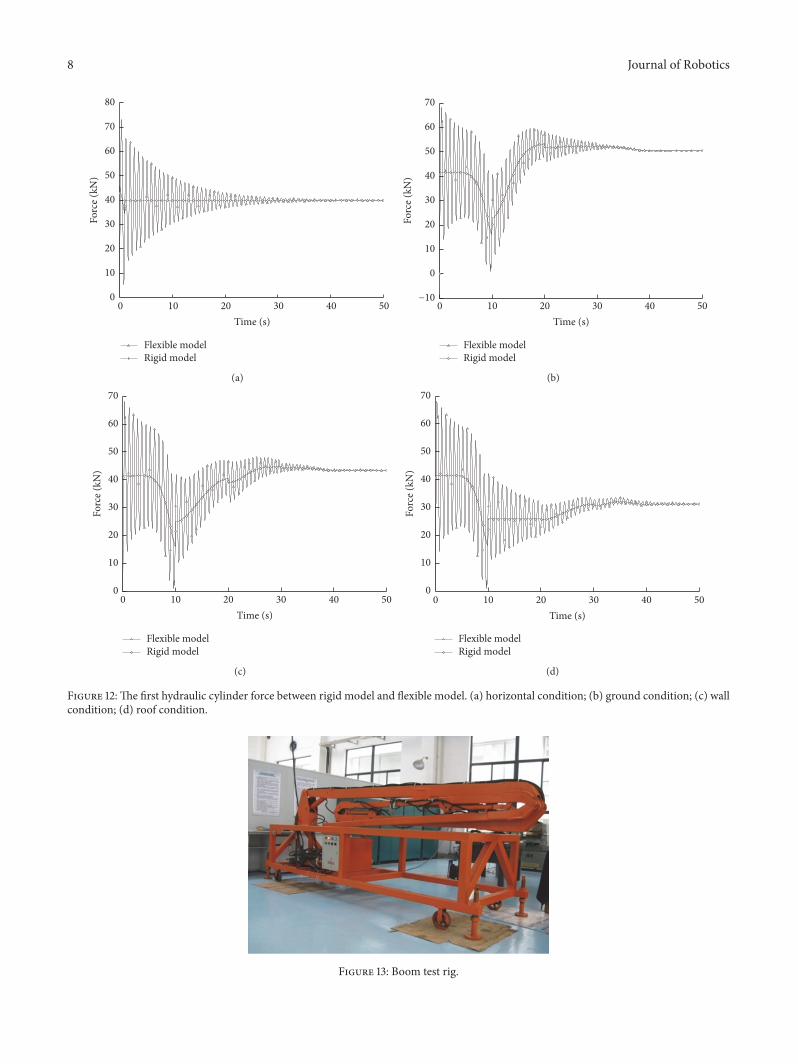