Modeling and analysis of nonlinear behavior for ...
6
IEICE Electronics Express, Vol.18, No.13, 1–6 LETTER Modeling and analysis of nonlinear behavior for synchronous switching Z-source topology Yan Chen 1 , Zhiyang Zhou 1 , Yong Zheng 2, a) , and Lin Zhong 1 Abstract As a high-performance step-up/step-down converter, the syn- chronous switching Z-source overcomes the theoretical obstacles and limi- tations of traditional voltage source and current source converters. However, due to the existence of switching devices, the system has strong nonlinear characteristics. At the same time, it belongs to a high-order system, which is easily affected by changes in environment and structural parameters, causing local system instability, namely bifurcation and chaos. To solve the above problems, the discrete iterative model is established on the basis of the state equation of the system, the steady-state operating point of the sys- tem was analyzed by nonlinear theory, and the mechanism of the nonlinear behavior was revealed, so as to determine the parameter conditions of the system stability region. Compared with solving the differential equation di- rectly, this paper maps the discrete iterative model to the complex frequency domain for solution, which can greatly reduce the amount of calculation while ensuring the accuracy of the model. The analysis provides the pa- rameter basis for the stable operation of the system and provides theoretical support for further optimization of the system design. Keywords: synchronous switching converter, bifurcation, nonlinear behav- ior, Z-source topology Classification: Circuits and modules for storage 1. Introduction As the core component of power transformation, switch- ing converter plays an important role in energy transfer, and is widely used in new energy power generation, rail transit equipment, new energy electric vehicles and other fields. With the deepening of power electronics technology research, some phenomena such as unknown electromag- netic noise, intermittent instability or sudden collapse of the system in the circuit system under certain conditions have gradually attracted the attention of researchers. With the gradual establishment of nonlinear dynamics theory [1, 2] and the continuous in-depth study of converters, it is grad- ually realized that these phenomena are the manifestations of bifurcation and chaos in nonlinear behavior in power electronic converters. The switching converter has a non- linear variable structure control system. The on-off or off of the power switch tube makes the system switch period- ically in different structures, which will lead to complex 1 School of Electrical and Electronic Engineering, Chongqing University of Technology, Chongqing, China 2 Engineering Research Center of Mechanical Testing Technol- ogy and Equipment, Ministry of Education, Chongqing Uni- versity of Technology, Chongqing, China a) [email protected] DOI: 10.1587/elex.18.20210209 Received May 12, 2021 Accepted June 2, 2021 Publicized June 15, 2021 Copyedited July 10, 2021 nonlinear behaviors of the switching converter, such as pe- riod doubling bifurcation [3, 4], Hopf bifurcation [5, 6], Flip bifurcation [7, 8], boundary collision bifurcation, and even chaos [9, 10], subharmonic oscillation [11]. As a new type of converter, Z-source converter was first pro- posed by Professor Peng Fangzheng in 2002 [12]. Z-source converter [13, 14] introduces a unique impedance source network to connect the input and output, so that any loop in the converter topology contains inductive elements, which can effectively suppress the spikes generated by the switch- ing commutation. Therefore, many improved derivative topologies have emerged [15, 16, 17]. However, the in- troduction of Z-source network also increases the order of the circuit, which makes the nonlinear dynamic behavior of Z-source converter more complex [18]. Compared with the traditional boost, buck converter, the nonlinear behav- ior has been studied maturely [19, 20], the current Z source nonlinear behavior research is still in its infancy, only ap- peared in some topologies [21, 22, 23]. At present, the existing researches on Z-source DC conversion are based on the combination of diode and switch tube complemen- tary conduction control [24, 25, 26]. Replacing diode with switch tube for synchronous control is more conducive to efficiency improvement, but it is easy to produce nonlinear behavior. As a kind of Z-source group, synchronous Z-source con- verter is more likely to produce nonlinear behavior because of its two switches are controlled and the equivalent circuit is different from the traditional Z-source. In reference [27], a mapping model is established by solving the second-order differential equation for the nonlinear behavior analysis of synchronous switch Z source, the iterative equation [28] is too complex, and the research will be hindered by the in- crease of system complexity. In this paper, an accurate strobe iterative model was established on the basis of the system state equation, and the model was solved in the mapping to the complex frequency domain [29, 30]. While ensuring the accuracy of the model, the computational complexity was greatly reduced and the processor memory space was saved. Furthermore, the critical value trajectory of the system in the stability domain with the change of parameters was further analyzed.This provides the parameter basis for the stable op- eration of the system, and provides the theoretical support for the further optimization of the system design. Copyright © 2021 The Institute of Electronics, Information and Communication Engineers 1
Transcript of Modeling and analysis of nonlinear behavior for ...

IEICE Electronics Express, Vol.18, No.13, 1–6
LETTER
Modeling and analysis of nonlinear behavior for synchronous switchingZ-source topology
Yan Chen1, Zhiyang Zhou1, Yong Zheng2, a), and Lin Zhong1
Abstract As a high-performance step-up/step-down converter, the syn-chronous switching Z-source overcomes the theoretical obstacles and limi-tations of traditional voltage source and current source converters. However,due to the existence of switching devices, the system has strong nonlinearcharacteristics. At the same time, it belongs to a high-order system, whichis easily affected by changes in environment and structural parameters,causing local system instability, namely bifurcation and chaos. To solve theabove problems, the discrete iterative model is established on the basis ofthe state equation of the system, the steady-state operating point of the sys-tem was analyzed by nonlinear theory, and the mechanism of the nonlinearbehavior was revealed, so as to determine the parameter conditions of thesystem stability region. Compared with solving the differential equation di-rectly, this paper maps the discrete iterative model to the complex frequencydomain for solution, which can greatly reduce the amount of calculationwhile ensuring the accuracy of the model. The analysis provides the pa-rameter basis for the stable operation of the system and provides theoreticalsupport for further optimization of the system design.Keywords: synchronous switching converter, bifurcation, nonlinear behav-ior, Z-source topologyClassification: Circuits and modules for storage
1. Introduction
As the core component of power transformation, switch-ing converter plays an important role in energy transfer,and is widely used in new energy power generation, railtransit equipment, new energy electric vehicles and otherfields. With the deepening of power electronics technologyresearch, some phenomena such as unknown electromag-netic noise, intermittent instability or sudden collapse of thesystem in the circuit system under certain conditions havegradually attracted the attention of researchers. With thegradual establishment of nonlinear dynamics theory [1, 2]and the continuous in-depth study of converters, it is grad-ually realized that these phenomena are the manifestationsof bifurcation and chaos in nonlinear behavior in powerelectronic converters. The switching converter has a non-linear variable structure control system. The on-off or offof the power switch tube makes the system switch period-ically in different structures, which will lead to complex
1 School of Electrical and Electronic Engineering, ChongqingUniversity of Technology, Chongqing, China
2 Engineering Research Center of Mechanical Testing Technol-ogy and Equipment, Ministry of Education, Chongqing Uni-versity of Technology, Chongqing, China
DOI: 10.1587/elex.18.20210209Received May 12, 2021Accepted June 2, 2021Publicized June 15, 2021Copyedited July 10, 2021
nonlinear behaviors of the switching converter, such as pe-riod doubling bifurcation [3, 4], Hopf bifurcation [5, 6],Flip bifurcation [7, 8], boundary collision bifurcation, andeven chaos [9, 10], subharmonic oscillation [11]. As anew type of converter, Z-source converter was first pro-posed by Professor Peng Fangzheng in 2002 [12]. Z-sourceconverter [13, 14] introduces a unique impedance sourcenetwork to connect the input and output, so that any loop inthe converter topology contains inductive elements, whichcan effectively suppress the spikes generated by the switch-ing commutation. Therefore, many improved derivativetopologies have emerged [15, 16, 17]. However, the in-troduction of Z-source network also increases the order ofthe circuit, which makes the nonlinear dynamic behaviorof Z-source converter more complex [18]. Compared withthe traditional boost, buck converter, the nonlinear behav-ior has been studied maturely [19, 20], the current Z sourcenonlinear behavior research is still in its infancy, only ap-peared in some topologies [21, 22, 23]. At present, theexisting researches on Z-source DC conversion are basedon the combination of diode and switch tube complemen-tary conduction control [24, 25, 26]. Replacing diode withswitch tube for synchronous control is more conducive toefficiency improvement, but it is easy to produce nonlinearbehavior.
As a kind of Z-source group, synchronous Z-source con-verter is more likely to produce nonlinear behavior becauseof its two switches are controlled and the equivalent circuitis different from the traditional Z-source. In reference [27],a mapping model is established by solving the second-orderdifferential equation for the nonlinear behavior analysis ofsynchronous switch Z source, the iterative equation [28]is too complex, and the research will be hindered by the in-crease of system complexity. In this paper, an accurate strobeiterative model was established on the basis of the systemstate equation, and the model was solved in the mapping tothe complex frequency domain [29, 30]. While ensuring theaccuracy of the model, the computational complexity wasgreatly reduced and the processor memory space was saved.Furthermore, the critical value trajectory of the system in thestability domain with the change of parameters was furtheranalyzed.This provides the parameter basis for the stable op-eration of the system, and provides the theoretical supportfor the further optimization of the system design.
Copyright © 2021 The Institute of Electronics, Information and Communication Engineers1

IEICE Electronics Express, Vol.18, No.13, 1–6
2. Working principle and modeling of synchronousswitching Z-source converter
2.1 Working principle of synchronous switching Z-source converter
The peak current controlled synchronous switching Z-sourceconverter is shown in Fig. 1. It is composed of voltage sourceVin, switch tube Q1, Q2 and Z-source network and load. Forthe convenience of analysis, take L1 = L2, C1 = C2. Inthe inductor current continuous mode, the system has twooperating modes, mode 1, two switches are switched on atthe same time, the power Vin supply charges the inductorsL1, L2 and capacitors C1, C2 in the Z-source network, theinductor current iL rises, when the inductor current increasesto the reference current Ire f , it will reset the trigger throughthe comparator; in mode 2, when the switch tube Q1 andQ2 are turned off at the same time, the Z-source networksupplies power to the load R, and the inductance current iLdrops, after a operating cycle until the switch tube is turnedon again.
Fig. 1 Synchronous switch Z-source converter under peak current control.
2.2 State equation of synchronous switching Z-sourceconverter
Based on the working principle of synchronous switchingZ-source converter, in order to clearly reflect the chargingprocess, the capacitor rc can be considered in the Z-sourcenetwork under the inductor current continuous mode. Takethe state variable of the system as X = [iL(t), VC(t)]T, iL(t)represents the current flowing through the inductor, namediL1, iL2, and VC(t) is the voltage across the capacitor C1 orC2. Suppose dn is the duty cycle of the driving signal of thesynchronous switching Z-source converter in the nth cycle,and satisfies 0 ⩽ dn ⩽ 1.
When the synchronous switching Z-source converter op-erates in Mode1, the state equation of the system is
Ûx = A1x + B1E (1)
Where A1 =
[0 00 −1/(rcC)
], B1 =
[1/(2L)
1/(2rcC)
]. When the
synchronous switching Z-source converter operates in Mode2, the equation of the system is
Ûx = A2x + B2E (2)
Where, A2 =
[−2(RL + rc) 1/L
−1/C 0
], B2 =
[00
].
3. The establishment of discrete iterative equation
Since the synchronous switching Z-source converter is apiecewise nonlinear system under the action of the periodicswitching of the power switch, it is difficult to analyze thestability of its nonlinear dynamic behavior directly throughthe state equation, so it is necessary to establish its discretemapping equation to analyze it. The stroboscopic samplingmethod can be used to solve the discrete iterative equationof the system. Let dn be the duty cycle of the nth cycle,the state variable of the nth cycle is xn = x(nT), and thedefinition of other discrete parameters can be deduced byanalogy, then the discrete iterative equation can be writtenas
xn+1 = f (xn, dn) (3)
The two state equations of the switching converter can beexpressed as
Ûx = A1x + B1E nT < t < nT + dnT (4)
Ûx = A2x + B2E nT + dnT < t < (n + 1)T (5)
Where E represents the input voltage, namely E = Vin. Forthe system described by the state equation Ûx = Ax + BE , thecomplex frequency domain solution is
X(s) = ϕ(s) [x(0−) + BE(s)] (6)
Where ϕ(s) = (sI-A)−1. Then the inverse Laplace transformis carried out to obtain the solution of the state equation
X(t) = ϕ(t)X(0−) +∫ t
0−ϕ(t − τ)BE(τ)dτ (7)
Where ϕ(t) = eAt . The discrete model under stroboscopicmap is
x(n + 1) = eAT x(n) +∫ T
0eA(T−τ)BE(τ)dτ (8)
From the state equations (1) and (2) of the system, the dis-crete model of the system in the nth period can be obtainedas
x(tn + dnT) = ϕ1(dnT)x(tn)
+
∫ tn+dnT
tn
ϕ1(tn + dnT − τ)B1Edτ
= ϕ1(dnT)x(tn)+∫ dnT
0ϕ1(tn+dnT−τ)B1Edτ
(nT < t < nT + dnT) (9)
x(tn+1) = ϕ2(dnT)x(tn + dnT)
+
∫ tn+T
tn+dnT
ϕ2(tn + T − τ)B2Edτ
= ϕ2(dnT)x(tn + dnT) +∫ dnT
0ϕ2(tn + T − τ)B2Edτ
(nT + dnT < t < (n + 1)T) (10)
2
IEICE Electronics Express, Vol.18, No.13, 1–6
ϕ1(dnT) = eA1dnT , ϕ2(dnT) = eA2dnT , dn = 1 − dn. Notethat A1 is irreversible and A2 is reversible, so the integralterms in the above two formulas are simplified
x(tn + dnT) = ϕ1(dnT)xn + B1EdnT (11)
x(tn+1) = ϕ2(dnT)x(tn + dnT)+ (ϕ2(dnT) − 1)A−1
2 B2E (12)
The discrete mapping equation is obtained by substituting(11) into (12)
xn+1 = f (xn, dn)= φ2(dnT)φ1(dnT)xn + φ2(dnT)B1EdnT
+ (φ2(dnT) − 1)A−12 B2E (13)
Define switch function
s(xn, dn) = ire f − iL= ire f + k1xn = ire f + k1x(tn + dnT)= ire f + k1ϕ1(dnT)xn + k1B1EdnT (14)
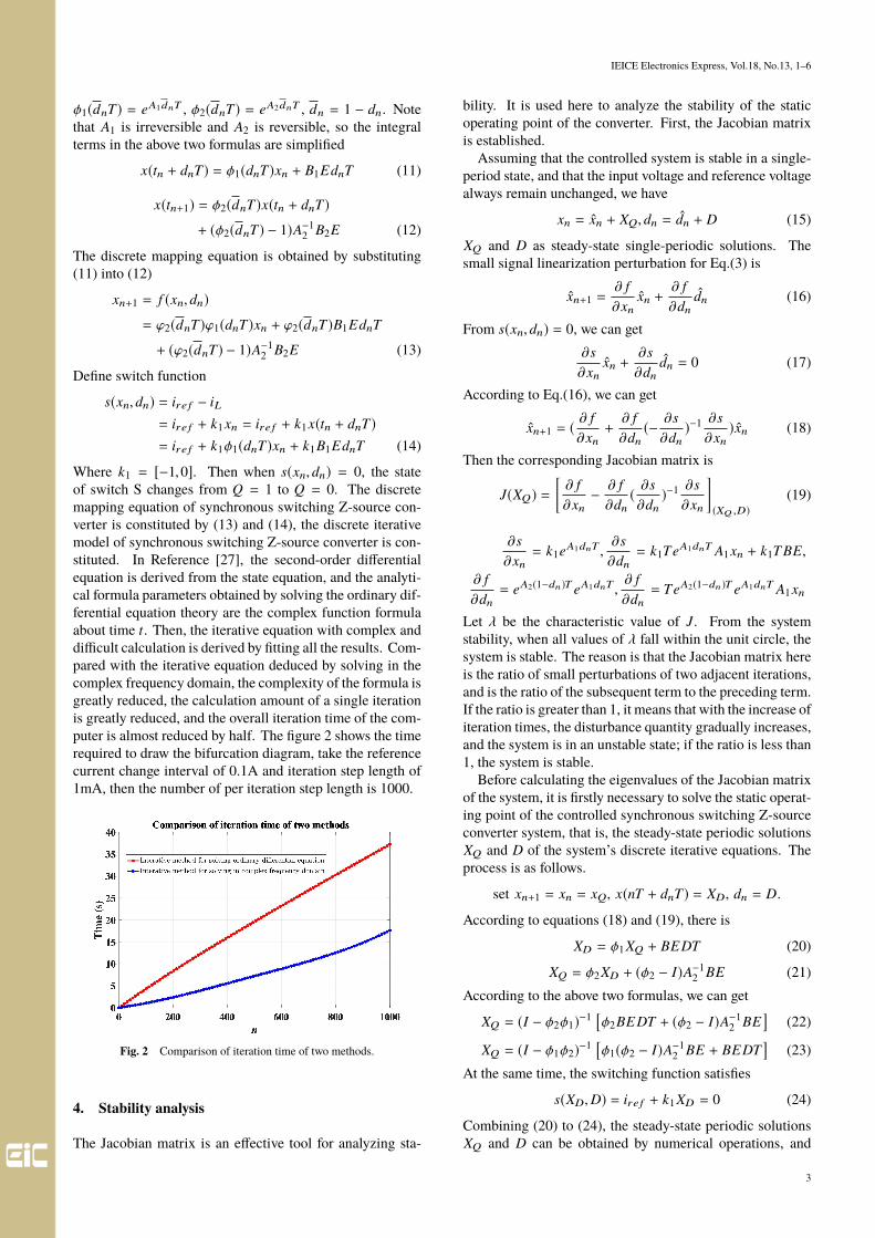
Where k1 = [−1,0]. Then when s(xn, dn) = 0, the stateof switch S changes from Q = 1 to Q = 0. The discretemapping equation of synchronous switching Z-source con-verter is constituted by (13) and (14), the discrete iterativemodel of synchronous switching Z-source converter is con-stituted. In Reference [27], the second-order differentialequation is derived from the state equation, and the analyti-cal formula parameters obtained by solving the ordinary dif-ferential equation theory are the complex function formulaabout time t. Then, the iterative equation with complex anddifficult calculation is derived by fitting all the results. Com-pared with the iterative equation deduced by solving in thecomplex frequency domain, the complexity of the formula isgreatly reduced, the calculation amount of a single iterationis greatly reduced, and the overall iteration time of the com-puter is almost reduced by half. The figure 2 shows the timerequired to draw the bifurcation diagram, take the referencecurrent change interval of 0.1A and iteration step length of1mA, then the number of per iteration step length is 1000.
Fig. 2 Comparison of iteration time of two methods.
4. Stability analysis
The Jacobian matrix is an effective tool for analyzing sta-
bility. It is used here to analyze the stability of the staticoperating point of the converter. First, the Jacobian matrixis established.
Assuming that the controlled system is stable in a single-period state, and that the input voltage and reference voltagealways remain unchanged, we have
xn = xn + XQ, dn = dn + D (15)
XQ and D as steady-state single-periodic solutions. Thesmall signal linearization perturbation for Eq.(3) is
xn+1 =∂ f∂xn
xn +∂ f∂dn
dn (16)
From s(xn, dn) = 0, we can get∂s∂xn
xn +∂s∂dn
dn = 0 (17)
According to Eq.(16), we can get
xn+1 = ( ∂ f∂xn+∂ f∂dn
(− ∂s∂dn
)−1 ∂s∂xn
)xn (18)
Then the corresponding Jacobian matrix is
J(XQ) =[∂ f∂xn
− ∂ f∂dn
( ∂s∂dn
)−1 ∂s∂xn
](XQ ,D)
(19)
∂s∂xn= k1eA1dnT ,
∂s∂dn= k1TeA1dnT A1xn + k1T BE,
∂ f∂dn= eA2(1−dn)T eA1dnT ,
∂ f∂dn= TeA2(1−dn)T eA1dnT A1xn
Let λ be the characteristic value of J. From the systemstability, when all values of λ fall within the unit circle, thesystem is stable. The reason is that the Jacobian matrix hereis the ratio of small perturbations of two adjacent iterations,and is the ratio of the subsequent term to the preceding term.If the ratio is greater than 1, it means that with the increase ofiteration times, the disturbance quantity gradually increases,and the system is in an unstable state; if the ratio is less than1, the system is stable.
Before calculating the eigenvalues of the Jacobian matrixof the system, it is firstly necessary to solve the static operat-ing point of the controlled synchronous switching Z-sourceconverter system, that is, the steady-state periodic solutionsXQ and D of the system’s discrete iterative equations. Theprocess is as follows.
set xn+1 = xn = xQ, x(nT + dnT) = XD, dn = D.
According to equations (18) and (19), there is
XD = ϕ1XQ + BEDT (20)
XQ = ϕ2XD + (ϕ2 − I)A−12 BE (21)
According to the above two formulas, we can get
XQ = (I − ϕ2ϕ1)−1 [ϕ2BEDT + (ϕ2 − I)A−12 BE
](22)
XQ = (I − ϕ1ϕ2)−1 [ϕ1(ϕ2 − I)A−12 BE + BEDT
](23)
At the same time, the switching function satisfies
s(XD,D) = ire f + k1XD = 0 (24)
Combining (20) to (24), the steady-state periodic solutionsXQ and D can be obtained by numerical operations, and
3

IEICE Electronics Express, Vol.18, No.13, 1–6
on this basis, the eigenvalues of the Jacobian matrix can beobtained to judge the stability of the system.
According to the schematic diagram of the peak currentmode controlled synchronous switching Z-source convertershown in Fig. 1, the eigenvalues of Jacobian matrix arecalculated according to the following parameters.
L = 2mH,R = 20Ω, C = 2000µF, Ire f = 0.1 ∼ 2.1A
For example, when |λmax | = max |λ1 | , |λ2 |. As can beseen from Fig. 3, when the eigenvalue reaches the point(−1,0) on unit circle, there is a boundary where the systementers into instability. That is, the system enters into anunstable periodic bifurcation state when Ire f increases to acertain value.
Fig. 3 Refers to the motion trajectory of system eigenvalues when thecurrent changes.
In order to intuitively obtain the position coordinates ofthe bifurcation point, the maximum module characteristicvalue is plotted as a change trajectory map, as shown inFig. 4. When the maximum eigenvalue changes to a certainpoint, |λmax | will exceed 1 when Ire f taking a value between0.3A and 0.4A, thus causing the system to enter an unstablestate.
Fig. 4 Trajectories of the maximum module characteristic values of theJacobian matrix.
According to the characteristics of the synchronousswitching Z converter system, the reference current is usedas the bifurcation parameter for simulation, and the otherparameters of the circuit remain unchanged. When the ref-erence current Ire f changes in interval 0.1A to 2.1A, thebifurcation of inductor current IL is shown in Fig. 5. WhenIre f = 0.37A, the system bifurcates from period 1 to pe-riod 2. When Ire f = 0.67A, period-doubling bifurcationoccurs again, and when Ire f = 1.2A, the system enters intoa chaotic state. The figure 4 shows the whole process of the
system entering chaos through period-doubling bifurcationwith the change of the reference current.
Fig. 5 Bifurcation diagram of inductance current with change of referencecurrent Iref
When Ire f = 2.1, the system has entered a chaotic state.At this time, the change of state is observed through thephase diagram of inductance current and capacitor voltageof the Z-source network. Fig. 6 shows the operating statediagram of the phase trajectory.
Fig. 6 Inductance current and capacitance voltage of phase trajectory.
5. Parameter analysis of system stable operation region
The position of bifurcation point can be accurately judgedby the change of eigenvalue of Jacobian matrix, and thesystem parameters can be set within a period to ensure thatthe system works in a stable region. As shown in Fig. 7,
Fig. 7 Spatial distribution diagram of system stability region with param-eter changes.
4
IEICE Electronics Express, Vol.18, No.13, 1–6
the peak reference current Ire f , inductance current L of Z-source and load R were selected as the spatial distributiondiagram of the stability region of variation.
6. Numerical simulation and experimental analysis
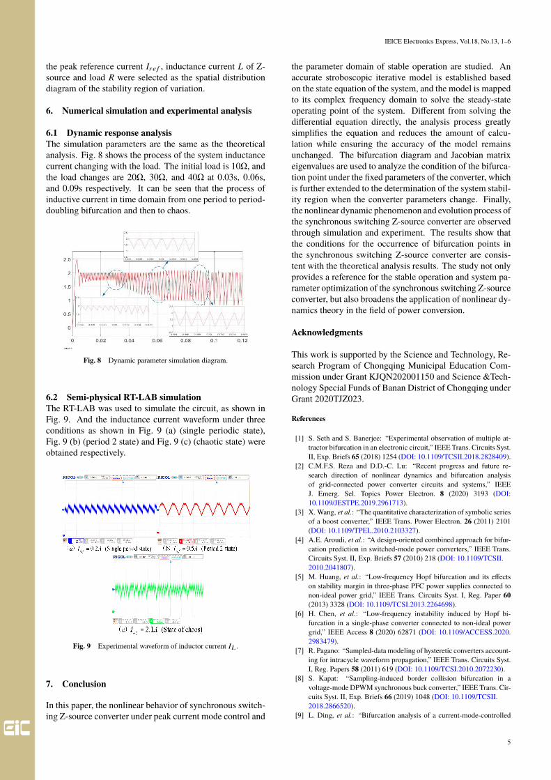
6.1 Dynamic response analysisThe simulation parameters are the same as the theoreticalanalysis. Fig. 8 shows the process of the system inductancecurrent changing with the load. The initial load is 10Ω, andthe load changes are 20Ω, 30Ω, and 40Ω at 0.03s, 0.06s,and 0.09s respectively. It can be seen that the process ofinductive current in time domain from one period to period-doubling bifurcation and then to chaos.
Fig. 8 Dynamic parameter simulation diagram.
6.2 Semi-physical RT-LAB simulationThe RT-LAB was used to simulate the circuit, as shown inFig. 9. And the inductance current waveform under threeconditions as shown in Fig. 9 (a) (single periodic state),Fig. 9 (b) (period 2 state) and Fig. 9 (c) (chaotic state) wereobtained respectively.
Fig. 9 Experimental waveform of inductor current IL .
7. Conclusion
In this paper, the nonlinear behavior of synchronous switch-ing Z-source converter under peak current mode control and
the parameter domain of stable operation are studied. Anaccurate stroboscopic iterative model is established basedon the state equation of the system, and the model is mappedto its complex frequency domain to solve the steady-stateoperating point of the system. Different from solving thedifferential equation directly, the analysis process greatlysimplifies the equation and reduces the amount of calcu-lation while ensuring the accuracy of the model remainsunchanged. The bifurcation diagram and Jacobian matrixeigenvalues are used to analyze the condition of the bifurca-tion point under the fixed parameters of the converter, whichis further extended to the determination of the system stabil-ity region when the converter parameters change. Finally,the nonlinear dynamic phenomenon and evolution process ofthe synchronous switching Z-source converter are observedthrough simulation and experiment. The results show thatthe conditions for the occurrence of bifurcation points inthe synchronous switching Z-source converter are consis-tent with the theoretical analysis results. The study not onlyprovides a reference for the stable operation and system pa-rameter optimization of the synchronous switching Z-sourceconverter, but also broadens the application of nonlinear dy-namics theory in the field of power conversion.
Acknowledgments
This work is supported by the Science and Technology, Re-search Program of Chongqing Municipal Education Com-mission under Grant KJQN202001150 and Science &Tech-nology Special Funds of Banan District of Chongqing underGrant 2020TJZ023.
References
[1] S. Seth and S. Banerjee: “Experimental observation of multiple at-tractor bifurcation in an electronic circuit,” IEEE Trans. Circuits Syst.II, Exp. Briefs 65 (2018) 1254 (DOI: 10.1109/TCSII.2018.2828409).
[2] C.M.F.S. Reza and D.D.-C. Lu: “Recent progress and future re-search direction of nonlinear dynamics and bifurcation analysisof grid-connected power converter circuits and systems,” IEEEJ. Emerg. Sel. Topics Power Electron. 8 (2020) 3193 (DOI:10.1109/JESTPE.2019.2961713).
[3] X. Wang, et al.: “The quantitative characterization of symbolic seriesof a boost converter,” IEEE Trans. Power Electron. 26 (2011) 2101(DOI: 10.1109/TPEL.2010.2103327).
[4] A.E. Aroudi, et al.: “A design-oriented combined approach for bifur-cation prediction in switched-mode power converters,” IEEE Trans.Circuits Syst. II, Exp. Briefs 57 (2010) 218 (DOI: 10.1109/TCSII.2010.2041807).
[5] M. Huang, et al.: “Low-frequency Hopf bifurcation and its effectson stability margin in three-phase PFC power supplies connected tonon-ideal power grid,” IEEE Trans. Circuits Syst. I, Reg. Paper 60(2013) 3328 (DOI: 10.1109/TCSI.2013.2264698).
[6] H. Chen, et al.: “Low-frequency instability induced by Hopf bi-furcation in a single-phase converter connected to non-ideal powergrid,” IEEE Access 8 (2020) 62871 (DOI: 10.1109/ACCESS.2020.2983479).
[7] R. Pagano: “Sampled-data modeling of hysteretic converters account-ing for intracycle waveform propagation,” IEEE Trans. Circuits Syst.I, Reg. Papers 58 (2011) 619 (DOI: 10.1109/TCSI.2010.2072230).
[8] S. Kapat: “Sampling-induced border collision bifurcation in avoltage-mode DPWM synchronous buck converter,” IEEE Trans. Cir-cuits Syst. II, Exp. Briefs 66 (2019) 1048 (DOI: 10.1109/TCSII.2018.2866520).
[9] L. Ding, et al.: “Bifurcation analysis of a current-mode-controlled
5

IEICE Electronics Express, Vol.18, No.13, 1–6
DC cascaded system and applications to design,” IEEE J. Emerg. Sel.Topics Power Electron. 8 (2020) 3214 (DOI: 10.1109/JESTPE.2020.2964818).
[10] J.D. Morcillo, et al.: “Adaptive ramp technique for controlling chaosand subharmonic oscillations in DC–DC power converters,” IEEETrans. Power Electron. 31 (2016) 5330 (DOI: 10.1109/TPEL.2015.2487269).
[11] J.-G. Kang, et al.: “A time-domain-controlled current-mode buckconverter with wide output voltage range,” IEEE J. Solid-State Cir-cuits 54 (2019) 865 (DOI: 10.1109/JSSC.2018.2884912).
[12] F.Z. Peng: “Z-source inverter,” IEEE Trans. Ind. Appl. 39 (2003) 504(DOI: 10.1109/tia.2003.808920).
[13] M. Veerachary and P. Kumar: “Analysis and design of quasi-Z-sourceequivalent DC–DC boost converters,” IEEE Trans. Ind. Appl. 56(2020) 6642 (DOI: 10.1109/TIA.2020.3021372).
[14] G. Sen and M.E. Elbuluk: “Voltage and current-programmed modesin control of the Z-source converter,” IEEE Trans. Ind. Appl. 46(2010) 680 (DOI: 10.1109/TIA.2010.2040054).
[15] M. Nguyen, et al.: “A Comparison Between Single-Phase Quasi-Z-Source and Quasi-Switched Boost Inverters,” IEEE Transactions onIndustrial Electronics 62 (2015) 6336 (DOI: 10.1109/TIE.2015.2424201).
[16] Y. Zhou, et al.: “A Single-Phase PV Quasi-Z-Source InverterWith Reduced Capacitance Using Modified Modulation and Double-Frequency Ripple Suppression Control,” IEEE Transactions on PowerElectronics 31 (2015) 2166 (DOI: 10.1109/TPEL.2015.2432070).
[17] P.C. Loh, et al.: “Γ-Z-source inverters,” IEEE Trans. Power Electron.28 (2013) 4880 (DOI: 10.1109/TPEL.2013.2243755).
[18] D. Suni, et al.: “Impedance design of quasi-Z source network to limitdouble fundamental frequency voltage and current ripples in single-phase quasi-Z source inverter,” IEEE Energy Conversion Congressand Exposition (2013) 2745 (DOI: 10.1109/ECCE.2013.6647056).
[19] L. Wei-Guo, et al.: “Dynamic feedback controlling chaos in current-mode boost converter,” Chingese Physical Letter 24 (2007) 1837.
[20] L. Premalatha and P. Vanajaranjan: “Spectral analysis of DC-DC buckconverter with chaotic dynamics,” Annual IEEE India Conference(2005) 605 (DOI: 10.1109/INDCON.2005.1590243).
[21] H. Shen, et al.: “Hybrid Z-source boost DC-DC converters,” IEEETrans. Ind. Electron. 64 (2017) 310 (DOI: 10.1109/TIE.2016.2607688).
[22] K. Guo, et al.: “Nonlinear behavior in current mode research of Z-source DC/DC converter,” J. Applied Mechanics and Materials 44(2011) 1677 (DOI: 4028/AMM.44-47.1677).
[23] Y. Chen, et al.: “Nonlinear dynamic behavior of high-frequency iso-lation quasi-Z-source photovoltaic inverter,” IEICE Electron. Express15 (2018) 839 (DOI: 10.1587/elex.15.20180839).
[24] Y. Chen, and Z. Yong: “Nonlinear behavior of a Z-source DC/DCconverter based on dual-loop control,” J. Vibroengineering 17 (2015)544.
[25] S. Li, et al.: “Nonlinear dynamic behavior analysis of a DC/DCconverter with an ultra-high frequency Z-source converter,” J. Vibro-engineering 18 (2016) 5506 (DOI: 10.21595/jve.2016.17620).
[26] J. Liu, et al.: “Switched Z-source/quasi-Z-source DC-DC converterswith reduced passive components for photovoltaic systems,” IEEEAccess, 7 (2019) 40893 (DOI: 10.1109/ACCESS.2019.2907300).
[27] J.-J. Xiang, et al.: “Dynamical study of peak-current-mode controlledsynchronous switching Z-source converter,” J. Chinese Journal ofPhysics (in Chinese) 63 (2014) 120507.
[28] W. Ma, et al.: “Hopf bifurcation and its control in the one-cyclecontrolled cuk converter,” IEEE Trans. Circuits Syst. II, Exp. Briefs66 (2019) 1411 (DOI: 10.1109/TCSII.2018.2880868).
[29] J.W. Fan and H.S. Chung: “Bifurcation phenomena and stabiliza-tion with compensation ramp in converter with power semicon-ductor filter,” IEEE Trans. Power Electron. 32 (2017) 9424 (DOI:10.1109/TPEL.2017.2658189).
[30] S. Cui, et al.: “Nonlinear dynamic behavior analysis of high frequencyBoost converter,” 2017 IEEE International Electric Machines andDrives Conference (IEMDC) (2017) 1 (DOI: 10.1109/IEMDC.2017.8002130).
6