MODELING AND ANALYSIS OF HYDRO-GAS SUSPENSION UNIT
14
35 AE Proceedings of the 18 th Int. AMME Conference, 3-5 April, 2018 18 th International Conference on Applied Mechanics and Mechanical Engineering. Military Technical College Kobry El-Kobbah, Cairo, Egypt. MODELING AND ANALYSIS OF HYDRO-GAS SUSPENSION UNIT M. M. Abd-Alaziz*, A. M. Salem*, W. G. Ata* ABSTRACT Hydro-gas suspension systems cushion shocks and damp oscillations of vehicle hull when it moves on uneven terrain. The hydro-gas suspension provides the vehicle with proper ride comfort due to non-linear characteristics of hydro-gas units. The hydro-gas suspension system can store a large amount of potential energy; accordingly, it can withstand higher shocks than the torsion bar suspension. Consequently, it is preferred to be used in the design of vehicle suspension. In this paper, a mathematical model for hydro-gas unit used in BMR wheeled vehicle is established to evaluate its characteristics using Matlab /Simulink program. The mathematical model is validated experimentally using the data measured for the unit in laboratory using MTS (793) damper test system. The unit is tested using an input sine wave excitation by a frequency and amplitude corresponding to real road conditions. KEYWORDS Tracked vehicle suspension, hydro-gas suspension, hydro-gas unit. ----------------------------------------------------------------------------------------------------------------- * Egyptian Armed Forces.
Transcript of MODELING AND ANALYSIS OF HYDRO-GAS SUSPENSION UNIT

35 AE Proceedings of the 18th Int. AMME Conference, 3-5 April, 2018
18th International Conference on Applied Mechanics and Mechanical Engineering.
Military Technical College Kobry El-Kobbah,
Cairo, Egypt.
MODELING AND ANALYSIS OF HYDRO-GAS SUSPENSION UNIT
M. M. Abd-Alaziz*, A. M. Salem*, W. G. Ata*
ABSTRACT Hydro-gas suspension systems cushion shocks and damp oscillations of vehicle hull when it moves on uneven terrain. The hydro-gas suspension provides the vehicle with proper ride comfort due to non-linear characteristics of hydro-gas units. The hydro-gas suspension system can store a large amount of potential energy; accordingly, it can withstand higher shocks than the torsion bar suspension. Consequently, it is preferred to be used in the design of vehicle suspension. In this paper, a mathematical model for hydro-gas unit used in BMR wheeled vehicle is established to evaluate its characteristics using Matlab /Simulink program. The mathematical model is validated experimentally using the data measured for the unit in laboratory using MTS (793) damper test system. The unit is tested using an input sine wave excitation by a frequency and amplitude corresponding to real road conditions. KEYWORDS
Tracked vehicle suspension, hydro-gas suspension, hydro-gas unit. ----------------------------------------------------------------------------------------------------------------- * Egyptian Armed Forces.

36 AE Proceedings of the 18th Int. AMME Conference, 3-5 April, 2018
NOMENCLATURE
Q flow rate through the fixed orifice area β Bulk's modulus
Ao orifice area of main piston Cv viscous friction coefficient of the piston
Cd discharge coefficient ff viscous friction coefficient of the floating piston
ρ oil density mf mass of floating piston
P1 pressure in the lower chamber mp mass of piston
P2 pressure in the upper chamber Po initial pressure of nitrogen gas in gas chamber
PN pressure of nitrogen gas in gas chamber
V1 volume of lower chamber
Af floating piston area V2 volume of upper chamber
Ap piston area Vo initial volume of gas chamber
Ar rod area X floating piston displacement
v vehicle speed Z main piston displacement
a road wave length
INTRODUCTION In hydro-gas suspension system, instead of metallic torsion spring in a conventional mechanical torsion bar, gas is used to act as a spring medium. Hydraulic oil is filled to provide hydraulic damping to dissipate the energy, thus diminishing the successive amplitudes. Because their resilience is based on the compressibility of the gas, hydro-gas spring units have highly non-linear load-deflection characteristics. This makes it possible to obtain a low natural frequency when the road wheels are operating around their static position. At the same time it also provides a spring rate which rises rapidly as the road wheels approach the limit of their bump travel and thereby prevents the suspension arms from being forced against the bump stops by relatively small impacts, as would otherwise be the case. Other advantages of hydro-gas suspensions include their spring units being self-contained and normally bolted to the outside of hull side plates. This means that they do not add to the height of hulls, as torsion bars do, and that they need not take up any space within the armour envelope. In consequence, the use of hydro-gas suspensions can produce significant savings in the weight of tanks. Because they are self-contained, hydro-gas suspension units are simpler to install than the separate springs and dampers of other types of suspensions. Also, because each unit is a damper as well as a spring, they provide better damping, overall, than suspensions in which dampers are only fitted to some of the road wheels [1]. Fig (1) illustrates wheel force versus wheel travel for three different spring systems including the hydro-gas system. It can be seen from the figure that the hydro gas suspension system can hold more potential energy than the other two spring systems; consequently, it can withstand high shocks and vibrations.

37 AE Proceedings of the 18th Int. AMME Conference, 3-5 April, 2018
1. Standard torsion bar system 2. High strength torsion bar system 3. Hydro-gas spring system
Fig (1) Wheel force versus wheel travel of three different spring systems.
Solomon et al. [2] modeled a hydro-gas suspension system using polytrophic gas compression model to represent the spring characteristics and the damper orifices using hydraulic conductance. The analytical model is validated with experiments individually for spring and damper flow characteristics and then as a suspension-wheel assembly in special test rigs. Simulation is carried out for sinusoidal inputs of different wavelengths, amplitudes and vehicle speeds. Based on the validated model, the influence of suspension parameters on the ride comfort of a tracked vehicle is studied. Fig (2) shows the theoretical and experimental characteristics of the hydro-gas unit.
Fig (2) Force–deflection characteristics of hydro-gas suspension system.
Purdy and Kumar [3] developed a model of six-wheel tracked vehicle using Matlab/Simulink. The model is carried out to study the variation of different parameters of hydro-gas suspension unit such as suspension force and pressure difference across damper and their effect on the change of amplitude and frequency of fluctuation. Such effect is performed by varying the damper orifice from 1 to 8 mm at a frequency range from 0.1 to 30 HZ. They found that a damper orifice with diameter 3 mm is good compromise for ride performance over smooth and rough terrains. Rideout and Anderson [4] tested Hydro-gas suspension system from a Rover Group MGF sports car statically and dynamically to generate stiffness and damping

38 AE Proceedings of the 18th Int. AMME Conference, 3-5 April, 2018
coefficient matrices. The goal was to develop the simplest possible model of the system for use in ride quality studies. In this paper, a mathematical model for the hydro-gas suspension unit using Matlab/Simulink is established to determine its dynamic characteristics. The results obtained from the model were validated with experimental results obtained for the unit using MTS damper test system. MODELING OF HYDRO-GAS SUSPENSION UNIT The model describing the dynamic behavior of the hydro-gas unit was created using MATLAB/Simulink program. Some of hydro-gas model parameters are measured while the others are chosen. The model is used to determine the variation of the total force of the unit with displacement and velocity of its moving parts.
Description of the Hydro-Gas Unit
Fig (3) shows a functional scheme of the studied hydro gas suspension unit. The piston is attached to the end of the piston rod and works against hydraulic fluid and gas pressure in the main cylinder. As the piston travels up and down, the hydraulic fluid is forced through tiny holes, called orifices inside the piston. However, these orifices let only a small amount of fluid to pass through the piston. This slows down the motion of the piston, which in turn slows down spring and suspension movement.
1. piston rod 2. piston 3. cylinder case 4. gas chamber 5. floating piston 6. upper chamber 7. lower chamber
Fig (3) Schematic drawing of the hydro gas suspension unit.
Operation of the Hydro-Gas Unit
When the moving cylinder of the unit starts to move upwards due to road bumps during compression stroke, the oil pressure is increased and the cylinder starts to move upward causing an increase of the pressure inside the gas chamber. The gas
39 AE Proceedings of the 18th Int. AMME Conference, 3-5 April, 2018
spring effect is started in this direction and the oil flows from the lower chamber to the upper chamber through the fixed orifice area.In rebound, the moving cylinder of the hydro gas suspension unit starts to move downwards and the oil pressure in the lower chamber starts to decrease. The oil flows through the fixed orifice area to the lower chamber generating high damping force. At the same time, the cylinder starts to move downward causing a decrease of the gas pressure and the stiffness of the gas spring [6]. Mathematical Model Assumptions The mathematical model describing the dynamic behavior of the hydro-gas unit is based on the following assumptions [7-10]:
1- The density and bulk's modulus of oil are assumed constant 2- Coefficient of discharge is assumed constant 3- The variation of the viscosity of oil is neglected 4- There is no internal or external leakage of flow rate 5- The piston of the hydro-gas unit is initially in the middle of the stroke 6- Assuming adiabatic process for the nitrogen for compression and rebound
strokes The operation of the hydro gas suspension unit is divided into two modes which will be discussed in the following sections. Governing equations of hydro-gas suspension unit [11]. The flow rate of the oil through different orifices connected in parallel to the chamber (V1) and having different fixed areas (A01) and (A02) is given by:
ρ
)(2 12 PPAnCQ Od
−= (1)
The continuity equation in upper chamber (V1) is expressed by:
0]/)[( 1
111 =+−−dt
dPZAV
dt
dZAQ β (2)
and the continuity of oil flow in the chamber (V2) is described by:
0]/)[( 2222 =+−−−−
dt
dPxAZAV
dt
dXAQ
dt
dZA ff β (3)
Where�� = �� − ��anddt
dPZAV 1
11 ]/)[( β+ is a term allowing the effect of the
compressibility in the chamber (V1) and �� = ��and �� ��� ��� � ���/�� is a term
expressing the effect of the compressibility in the chamber (V2). The equation describing the movement of the floating piston is determined according to the difference between the oil pressure and the nitrogen gas pressure, the resistance of floating piston weight, and the effect of viscous damping and it can be expressed by:

40 AE Proceedings of the 18th Int. AMME Conference, 3-5 April, 2018
dt
dXfgmAPP
dt
Xdm fffNf −−−= )( 22
2
(4)
The nitrogen gas pressure is determined from the equation
35.135.1
NNoo VPVP = (5)
The volume of the nitrogen gas is calculated from the volume difference between the initial volume of the nitrogen chamber and the volume of oil displaced to nitrogen chamber as given in the following equation:
XAVV fON −= (6)
Input data The parameters of the hydro gas suspension unit model are shown in Table (1).
Table (1) Parameters of BMR hydro-gas unit.
Parameters value Parameters value
Ao 2.37583×10⁻⁵[m2] ff 0.3 [Ns/m]
Af 0.003216 [m2] mf 1.316 [kg]
Ap 0.007697[m2] mp 2.248 [kg]
Ar 0.005026[m2] Po 10 [Mpa]
β 1.3×10 [Pa] V1 0.000520 [m3]
Cd 0.65 [Ns/m] V2 0.001039 [m3]
Cv 0.25 [Ns/m] Vo 0.001351 [m3]
NUMERICAL SOLUTION USING MATLAB/SIMULINK The SIMULINK program in MATLAB 7 is used to simulate the performance of the hydro-gas suspension unit described by equations. The input parameters of the program are the displacement and the velocity of the moving part. Fig (4) shows the main page of the hydro gas suspension unit SIMULINK program. Results and Analysis of Simulated Model The hydro gas suspension unit is excited by a sine wave excitation with frequencies and amplitudes corresponding to road conditions as will be explained later. The frequency of excitation is (1-5) HZ while the amplitude of excitation is (10-50) mm. The output of the program represents the force generated in the hydro gas suspension unit. This force was plotted versus time, displacement and velocity at excitation frequency 2 Hz and 25mm amplitude in Fig (5), Fig (6) and Fig (7) respectively.

41 AE Proceedings of the 18th Int. AMME Conference, 3-5 April, 2018
Fig (4) Main page of the hydro gas suspension unit SIMULINK program.
Fig (5) Force- time dependence.
Fig (6) Force – displacement dependence.
42 AE Proceedings of the 18th Int. AMME Conference, 3-5 April, 2018
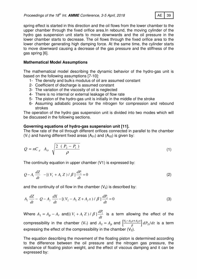
Fig (7) Force – velocity dependence. EXPERIMINTAL MEASUREMENT OF HYDRO-GAS UNIT The MTS damper test machine Model 853 shown in Fig. (8) is used to simulate the profile of different terrains. Variation of the damping force with velocity, displacement and variation of the peak force with the peak velocity at different frequencies and amplitudes for hydro-gas unit are obtained using the test machine. The oscillation of the vehicle produced by external forces and moments depends on the shape and geometry of the terrain unevenness as well as the speed of the vehicle. A typical road profile is shown in Fig. (9).The excitation frequency of the vehicle hull can be calculated according to the following relation [12]:
� = 2���
The test plan is defined according to an excitation frequency range from 1 to 5Hz and excitation amplitude range from 10 to 50 mm. These excitation conditions correspond to the actual frequency of damper on vehicle during its motion on rough terrain. These test parameters are realizing the prescribed road conditions.
Fig (8) MTS machine and hydro-gas unit.
Fig (9) Road profile.
43 AE Proceedings of the 18th Int. AMME Conference, 3-5 April, 2018
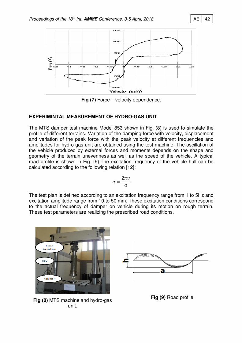
In all the graphical results presented, positive displacements, velocities and forces denote extension of the unit, while negative displacements, velocities and forces denote compression of the unit.
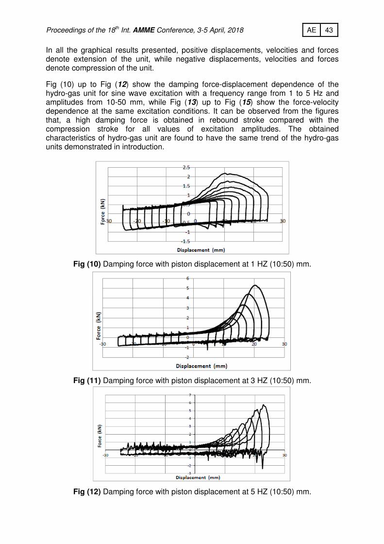
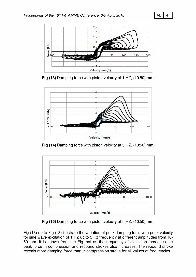
Fig (10) up to Fig (12) show the damping force-displacement dependence of the hydro-gas unit for sine wave excitation with a frequency range from 1 to 5 Hz and amplitudes from 10-50 mm, while Fig (13) up to Fig (15) show the force-velocity dependence at the same excitation conditions. It can be observed from the figures that, a high damping force is obtained in rebound stroke compared with the compression stroke for all values of excitation amplitudes. The obtained characteristics of hydro-gas unit are found to have the same trend of the hydro-gas units demonstrated in introduction.
Fig (10) Damping force with piston displacement at 1 HZ (10:50) mm.
Fig (11) Damping force with piston displacement at 3 HZ (10:50) mm.
Fig (12) Damping force with piston displacement at 5 HZ (10:50) mm.
44 AE Proceedings of the 18th Int. AMME Conference, 3-5 April, 2018
Fig (13) Damping force with piston velocity at 1 HZ, (10:50) mm.
Fig (14) Damping force with piston velocity at 3 HZ, (10:50) mm.
Fig (15) Damping force with piston velocity at 5 HZ, (10:50) mm.
Fig (16) up to Fig (18) illustrate the variation of peak damping force with peak velocity for sine wave excitation of 1 HZ up to 5 Hz frequency at different amplitudes from 10-50 mm. It is shown from the Fig that as the frequency of excitation increases the peak force in compression and rebound strokes also increases. The rebound stroke reveals more damping force than in compression stroke for all values of frequencies.

45 AE Proceedings of the 18th Int. AMME Conference, 3-5 April, 2018
Fig (16) Peak damping force with peak velocity at 1 HZ, (10:50) mm.
Fig (17) Peak damping force with peak velocity at 3 HZ, (10:50) mm.
Fig (18) Peak damping force with peak velocity at 5 HZ, (10:50) mm.
The characteristics of the hydro-gas unit of BMR wheeled vehicle are obtained from the previous data for a sine wave excitation. Fig (19) shows this characteristics at a frequency 2 HZ and at amplitude 30 mm which reveals nonlinear characteristics. VALIDATION OF THE MATHEMATICAL MODEL The mathematical model is validated using the experimental results obtained for the hydro-gas unit. A comparison between the results obtained experimentally with those obtained by the model is shown in the following Figures.

46 AE Proceedings of the 18th Int. AMME Conference, 3-5 April, 2018
Fig (19) Characteristics of hydro-gas unit.
Fig (20), Fig (21) and, Fig (22) show the variation of hydro-gas suspension unit force, with time, velocity, and displacement respectively. By comparing the experimental results with those of the numerical simulation, it can be found that there is a good agreement between the results; accordingly, the numerical simulation can simulate the actual characteristics of the hydro gas suspension unit with a good accuracy agreement The little distortion in simulating results is due to that the compressibility of oil not being accurately introduced. The research on more accurate mathematical model of the hydro-gas suspension unit will be included in a future work.
Fig (20) Force - time dependence for sinusoidal input at 2Hz and 25 mm.
Fig (21) Force - displacement dependence for sinusoidal input at 2Hz and 25 mm.

47 AE Proceedings of the 18th Int. AMME Conference, 3-5 April, 2018
Fig (22) Force - velocity dependence for sinusoidal input at 2Hz and 25 mm.
CONCLUSION Hydro-gas suspension system meets a lot of requirements of vehicle vibrational dynamics. For studying the response of the vehicle fitted with hydro-gas unit, its characteristics must be realized. A mathematical model of the hydro-gas unit of the BMR wheeled vehicle was realized and solved using Matlab/Simulink program to estimate the unit characteristics under different excitation conditions. The parameters used in the model were measured and obtained from experimental results. These characteristics were validated with data obtained from measurements performed on MTS (853) damper test system. The results revealed a non-linear characteristics and a higher potential energy as the hydro-gas unit can absorb more shocks and sustained both ride comfort and handling. The unit has a higher damping in rebound than in compression as it can retain the road wheel close to the terrain and provide better performance for the suspension system. The peak force plotted with peak velocity showed that as the excitation frequency increases, the speed of the piston increases in compression more than in rebound. REFERENCES [1] Janes's armored and artillery upgrades, twelfth edition, ISBN, 2000, pp.324- 328. [2] U. Solomon and Chandramouli Padmanabhan, " Hydro-gas suspension system for a
tracked vehicle: Modeling and analysis," Journal of Terramechanics Vol. 48, 2011 pp.125-137.
[3] David J. Purdy and J. Rajesh Kumar., "Mathematical modeling of hydro-gas suspension unit for tracked military vehicles," Journal of battle field technology Vol. 8, No. 3, November 2005.
[4] Geoff Rideout and Ronald J. Anderson., "Experimental Testing and Mathematical Modeling of the Interconnected Hydra-gas Suspension System," Society of Automotive Engineers, Inc. 2003 pp.442-449.
48 AE Proceedings of the 18th Int. AMME Conference, 3-5 April, 2018
[5] J. Y. Wong, "Theory of ground vehicles", Book 3rd edition, Carlton university, Candaa, ISBN 0-471-35461-9, 2001
[6] H.A. Hammad, "Effect of Undercarriage Design Parameters on Suspension Characteristic of Tracked Vehicles", MS.C thesis MTC ,Cairo, Egypt.May, 2010.
[7] Anil Dhir and Seshadri Sankar, "Assessment of Tracked Vehicle Suspension System Using a Validated Computer Simulation Model", Journal of Terramechanics, Vol. 32, No. 3, pp. 127-149, 1995.
[8] S.Sridhar, N.S.Sekar, "Optimization of Kinematics for Tracked Vehicle Hydro Gas Suspension System", Defence Science Journal, Vol. 56, No. 5, November 2006.
[9] Christiaan Lambert Giliomee, "Analysis of a Four State Switchable hydro-pneumatic Spring and Damper System", University of Pretoria, Copyright 2003, pp.6-12.
[10] S. Subramanian, R. Surampudi, "Development of a Nonlinear Shock Absorber Model for Low-Frequency NVH Applications", Daimler Chrysler Corporation, 2003.
[11] H. A. Hammad, A. M. Salem, I. Saleh Mostafa, I. A. Elsherif "Modeling of Hydrogas Unit for Tracked Vehicle Suspension", 16th International Conference on Aerospace Sciences and Aviation Technology MTC ,Cairo, Egypt, May 2015.
[12] Printed lecture of tanks department, Theory of suspension, M.T.C., Ciro, Egypt