Modeling and Analysis of 2-Stage Reduction Gear · PDF fileA reduction gear box is part of a...
8
Abstract: A reduction gear box is part of a mechanical system of gears and shafts used to reduce the rotational speed of the input shaft to a slower rotational speed of the output shaft. This reduction in output speed helps to increase the torque of a system. Reduction gears are widely used in power transmission devices to reduce the high rotational speeds. Gears have wide variety of applications. Gears are the most important component in power transmission sys- tem. The gears generally fail when tooth stress exceeds the safe limit. It is essential to determine the maximum stress that a gear tooth is subjected to, under a speci- fied loading. To prevent from failure Analysis is carried on gears. The present work is directed towards the modeling of 2-stage reduction gear box with its components like helical gears, pinions, integral shaft bearings and hous- ing in a 3D cad tool called SOLIDWORKS 2014sp1. This work investigates the characteristics of an involute he- lical gear system mainly focused on bending stresses using solid works simulation. The analytical study is conducted by using Lewis formula. The Study is con- ducted by varying the face width to find the bending stress of helical gear. Finally It is observed that the maximum bending stress decreases with increasing the face width of the gear. This study shows the complex design problem of helical gear and required superior software skills for modeling and analysis. I.INTRODUCTION: Power transmission states to convert speed and torque from one rotating power source to another. In this project to design and analysis on the intermediate shaft for stresses and deflections and it is necessary to know the applied forces. If the forces are transmit- ted through the gears, it is necessary to know the gear specifications. Puttapaka Nagaraju M.Tech Student, Machine design, Anurag engineering college. Ch. Ashok Kumar Assistant professor, Department of Mechanical Engineering Anurag Engineering College. Volume No: 1(2014), Issue No: 12 (December) December 2014 www.ijmetmr.com Page 391 ISSN No: 2348-4845 International Journal & Magazine of Engineering, Technology, Management and Research A Monthly Peer Reviewed Open Access International e-Journal To determine the forces that will be transmitted to the shaft. This project will focus on an overview of a power transmission system design, demonstrating how to in- corporate the details of each component into an over- all design process. A typical two-stage gear reduction box is been used to understand the design process. The design sequence is similar for variations of this particular transmission system. Figure 1: compound reverted gear train. Transmission: The term power transmission is defined as the move- ment of energy from input power source to output device to perform the work. . In mechanical power transmissions, a device is interposed between a source of power and a specific application for the purpose of adapting one to the other. Most mechanical transmis- sions are rotary speed changers; the ratio of the out- put speed to the input speed may be constant (as in a gearbox) or variable. In variable-speed transmissions the speed of the gear is varies in discrete steps or con- tinuously varies within the range. Types of power transmission systems: Transmissions types include •Manual Transmission Modeling and Analysis of 2-Stage Reduction Gear Box
-
Upload
truongdung -
Category
Documents
-
view
215 -
download
3
Transcript of Modeling and Analysis of 2-Stage Reduction Gear · PDF fileA reduction gear box is part of a...

Abstract:
A reduction gear box is part of a mechanical system of gears and shafts used to reduce the rotational speed of the input shaft to a slower rotational speed of the output shaft. This reduction in output speed helps to increase the torque of a system. Reduction gears are widely used in power transmission devices to reduce the high rotational speeds.
Gears have wide variety of applications. Gears are the most important component in power transmission sys-tem. The gears generally fail when tooth stress exceeds the safe limit. It is essential to determine the maximum stress that a gear tooth is subjected to, under a speci-fied loading. To prevent from failure Analysis is carried on gears.
The present work is directed towards the modeling of 2-stage reduction gear box with its components like helical gears, pinions, integral shaft bearings and hous-ing in a 3D cad tool called SOLIDWORKS 2014sp1. This work investigates the characteristics of an involute he-lical gear system mainly focused on bending stresses using solid works simulation. The analytical study is conducted by using Lewis formula. The Study is con-ducted by varying the face width to find the bending stress of helical gear. Finally It is observed that the maximum bending stress decreases with increasing the face width of the gear. This study shows the complex design problem of helical gear and required superior software skills for modeling and analysis.
I.INTRODUCTION:
Power transmission states to convert speed and torque from one rotating power source to another. In this project to design and analysis on the intermediate shaft for stresses and deflections and it is necessary to know the applied forces. If the forces are transmit-ted through the gears, it is necessary to know the gear specifications.
Puttapaka NagarajuM.Tech Student,Machine design,
Anurag engineering college.
Ch. Ashok KumarAssistant professor,
Department of Mechanical EngineeringAnurag Engineering College.
Volume No: 1(2014), Issue No: 12 (December) December 2014 www.ijmetmr.com Page 391
ISSN No: 2348-4845International Journal & Magazine of Engineering,
Technology, Management and ResearchA Monthly Peer Reviewed Open Access International e-Journal
To determine the forces that will be transmitted to the shaft. This project will focus on an overview of a power transmission system design, demonstrating how to in-corporate the details of each component into an over-all design process.
A typical two-stage gear reduction box is been used to understand the design process. The design sequence is similar for variations of this particular transmission system.
Figure 1: compound reverted gear train.
Transmission:
The term power transmission is defined as the move-ment of energy from input power source to output device to perform the work. . In mechanical power transmissions, a device is interposed between a source of power and a specific application for the purpose of adapting one to the other. Most mechanical transmis-sions are rotary speed changers; the ratio of the out-put speed to the input speed may be constant (as in a gearbox) or variable. In variable-speed transmissions the speed of the gear is varies in discrete steps or con-tinuously varies within the range.
Types of power transmission systems:
Transmissions types include•Manual Transmission
Modeling and Analysis of 2-Stage Reduction Gear Box

•Automatic Transmission.
•Semi-automatic transmission.
a)Manual transmission :
Manual transmissions are the most common type. These are cheaper, lighter; usually give better perfor-mance, and fuel efficiency. With a manual gear changer is used for new drivers to learn, and tested, on a car. Some manual transmissions have an extremely low ra-tio for first gear, called as creeper gear or granny gear. These types of gears are usually not synchronized. This feature is common in pickup trucks, farming, or con-struction-site work. During on-road use, the truck is driven without using the creeper gear and second gear is used from starting.
b) Semi-automatic:
Semi automatic transmission system is also called as clutch less or automated manual transmission. Many of these transmission systems by using control system to shift the gear from one to another. Semi-automatic systems used a variety of mechanical and hydraulic sys-tems - including centrifugal clutches, torque convert-ers, electro-mechanical (and even electrostatic) and servo/solenoid controlled clutches.
c) Automatic:
Automatic transmissions are easy to use. But in this type a number of problems are occur they were com-plex and expensive, sometimes had reliability problems have often been less fuel-efficient than their manual counterparts and their shift time was slower than a manual making.
Power Transmission Devices:
Power transmission devices are to transmit the power from one point to another point with their axis of mo-tion, and the devices are connected to each other by the following ways.
•Gear Drive•Chain Drive•Belt Drive
Volume No: 1(2014), Issue No: 12 (December) December 2014 www.ijmetmr.com Page 392
ISSN No: 2348-4845International Journal & Magazine of Engineering,
Technology, Management and ResearchA Monthly Peer Reviewed Open Access International e-Journal
a)Gear Drive:
Gears are toothed wheels that engage to transmit the rotary power from one point to another point. Gears are classified as follows:
b) Spur gears:
Spur gears are the most commonly used gear type. The teeth which are perpendicular to the face of the gear. Spur gears are most commonly available, and are gen-erally least expensive. The basic descriptive geometry for a spur gear is shown in the figure below.
figure: spur gear.
c) Helical Gears:
Helical gears are similar to the spur gears except that the teeth angle to the shaft. Helical gears are used to mesh two shafts are in not parallel, but they primar-ily used in parallel shaft applications. Helical gears can carry more loads compare to spur gears and transmits more power than spur gear.
Figure 2: helical gears
d) Bevel Gears: Bevel gears are primarily used to trans-mit the power in between intersecting shafts (the axis f the shafts are in not parallel). The teeth of these gears are formed on a conical surface. Hypocycloid bevel gears are a special type of spiral gear that will allow non-intersecting, non-parallel shafts to mesh. In high speed condition it can be noisy.
e) Worm Gears: Worm gears are special gears that re-semble screws, and used to drive spur gears or helical gears. Worm gears, like helical gears, allow two nonin-tersecting shafts. Normally, the two shafts are at right angles to each other. Worm gear is that it is a helical gear with a very high helix angle.
Figure 3: Worm Gears
Gear Trains:
A gear train is formed by mounting gears on a frame; the teeth’s of the gears are engage. Gear teeth are de-signed the pitch circles of engaging gears roll on each other without slipping and the module of both the gears are same, this provides a smooth transmission of rotation from one gear to the another gear.
Gears trains are classified into following types:
•Simple gear train.
•Compound gear train.
•Reverted compound gear train.
•Planetary gear train.
Volume No: 1(2014), Issue No: 12 (December) December 2014 www.ijmetmr.com Page 393
ISSN No: 2348-4845International Journal & Magazine of Engineering,
Technology, Management and ResearchA Monthly Peer Reviewed Open Access International e-Journal
a)Simple Gear Trains:
A simple gear train is used a large distance is covered between the input and output shafts. In this gear train each gear is mounted on its own shaft. Ina simple gear train each shaft carries only one train the expression for the simple train’s velocity ratio.
b) Compound gear trains:
In compound gear train at least one shaft carries more than one gear. In compound gear train to get the train ratio is greater than 10:1.there are four gears in the fig-ure gear 3 and 4 are mounted on single shaft and they have same angular velocity.The train ratio now:
Figure 4: Compound gear trainc) Reverted compound trains:
it is similar to the compound gear train but both they are used only a small space between the input and out-put shafts and large change in speed. There are two ma-jor differences between compound and reverted gear trains.First difference is the input and output shafts are lie on the same axis. Second, the distance between the centers of the two gears in each pair is same. Fig shows a reverted gear train

Figure 5: Reverted gear traind) Planetary Gear Trains:
A planetary gear train is more complex than other types of gear trains. In a planetary gear train at least one gear revolves around another gear in the gear train. . In this type of gear train the sun gear is located at the center of the system; the planet gear revolves around the sun gear. The whole system is held by the planet carrier.
II.REDUCTION GEAR BOX:
Reduction gear box consists of 2 gears having same no. Of teeth but different diameters. The number of teeth is proportional to the circumference of the gear; the smaller circumference gear will have fewer teeth than the larger one. The smaller gear makes two revolutions for every one revolution of large gear. The amount of torque obtained at larger gear is twice comparing to the torque available in smaller gear. The speed of the output gear is decreases and the torque is increasing proportionally.An automobile drive train is an example for multi-stage gear reduction system. An engine runs at 1500 to 3000 revolutions per minute (RPM).initially the vehicle is in stationary position. In this time it re-quires more torque to move the vehicle, but the en-gine runs more speed. By using reduction gear box to reduce the speed of the propeller shaft. By using differ-ent gear ratios used in gear box, the gear ratios are 3:1, 4:1, 5:1 and final gear ratio is 60:1.
Volume No: 1(2014), Issue No: 12 (December) December 2014 www.ijmetmr.com Page 394
ISSN No: 2348-4845International Journal & Magazine of Engineering,
Technology, Management and ResearchA Monthly Peer Reviewed Open Access International e-Journal
III.RELATED WORK:Introduction to solid-works:
Solid Works is mechanical design software and it is developed by DASSAULT SYSTEMS. It is easy-to-learn for mechanical designers to sketch ideas, features, di-mensions, produce models and detailed drawings. The modules consists of solid works are part, assembly and drawing etc.
Modeling Of 2-Stage Reduction Gear Box:Problem statement:
A helical reduction unit has to transmit30N-m input power of 12kw with a total reduction of 11.6. Speed N=1500 rpm. Applying Alloy steel material to the both pinion and gears.
Considering helix angle for helical teeth around 14 de-gree we consider that the pinion will be minimum 16 teeth.Let the pinions and gears have following teeth.Z1=16 and Z2=51 at the first stage and Z3=16 and Z4=58 at the second stage.
Figure 7: reducer sketch
Figure 8: tangential force.
Geometrical parameters of first stage:
Volume No: 1(2014), Issue No: 12 (December) December 2014 www.ijmetmr.com Page 395
ISSN No: 2348-4845International Journal & Magazine of Engineering,
Technology, Management and ResearchA Monthly Peer Reviewed Open Access International e-Journal
Table 1Geometrical parameters of second stage
Table 2Modeling of gear 1 in first stage:
Figure 9: gear1 of 51 teeth in the first stageModeling of pinion1 in first stage:
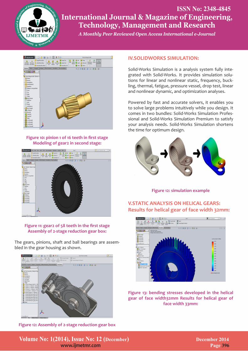
Figure 10: pinion 1 of 16 teeth in first stageModeling of gear2 in second stage:
Figure 11: gear2 of 58 teeth in the first stageAssembly of 2-stage reduction gear box:
The gears, pinions, shaft and ball bearings are assem-bled in the gear housing as shown.
Figure 12: Assembly of 2-stage reduction gear box
Volume No: 1(2014), Issue No: 12 (December) December 2014 www.ijmetmr.com Page 396
ISSN No: 2348-4845International Journal & Magazine of Engineering,
Technology, Management and ResearchA Monthly Peer Reviewed Open Access International e-Journal
IV.SOLIDWORKS SIMULATION:
Solid-Works Simulation is a analysis system fully inte-grated with Solid-Works. It provides simulation solu-tions for linear and nonlinear static, frequency, buck-ling, thermal, fatigue, pressure vessel, drop test, linear and nonlinear dynamic, and optimization analyses.
Powered by fast and accurate solvers, it enables you to solve large problems intuitively while you design. It comes in two bundles: Solid-Works Simulation Profes-sional and Solid-Works Simulation Premium to satisfy your analysis needs. Solid-Works Simulation shortens the time for optimum design.
Figure 12: simulation example
V.STATIC ANALYSIS ON HELICAL GEARS:Results for helical gear of face width 32mm:
Figure 13: bending stresses developed in the helical gear of face width32mm Results for helical gear of
face width 33mm:
Figure 14: bending stresses developed in the helical gear of face width33mm Results for helical gear of
face width 34mm:
Figure 15: bending stresses developed in the helical gear of face width34mm Results for Helical Gear of
Face Width 35mm:
Figure 16: bending stresses developed in the helical gear of face width35mm.
Volume No: 1(2014), Issue No: 12 (December) December 2014 www.ijmetmr.com Page 397
ISSN No: 2348-4845International Journal & Magazine of Engineering,
Technology, Management and ResearchA Monthly Peer Reviewed Open Access International e-Journal
Figure 17: bending stresses developed in the helical gear of face width36mm
RESULTS AND DISCUSSIONS
The structural analysis of helical gear is carried by us-ing FEA in solid works simulation. The load is applied on the gear tooth by applying analysis to perform the analysis and results are evaluated. Face width is an im-portant parameter in design of a gear. To change the face width of the gear the bending stress values are compared to theoretical values. The face widths of the gears are 32 mm to 36 mm respectively. From results with the increase of face width decreases the bending stress on gear tooth.
Comparison of theoretical stress values and solid works values:
Table 3

VI.CONCLUSIONS:
The 2-stage reduction gear box with all its components like helical gears, pinions, integral shaft and radial ball bearings are modeled in a 3D cad tool called SOLID-WORKS 2014.and analysis is done in solid works simula-tion. The strength of the gear is an important param-eter while designing a gear. In this project to compare the theoretical and simulation values of helical gear by varying the face width of the gear. Finally the design is safe.
REFERENCES:
1.Cheng, Y., And Tasy C.B., Stress Analysis Of Helical Gear Set With Localized Bearing.
2.Contact, Finite Element In Analysis And Design, 38,Pp. 707-723, 2002 Vijayarangan, s., and Ganesan, n., a static analysis of composite helical gears using three dimen-sional finite element method, computers & structures, 49,pp.253-268,1993.
Volume No: 1(2014), Issue No: 12 (December) December 2014 www.ijmetmr.com Page 398
ISSN No: 2348-4845International Journal & Magazine of Engineering,
Technology, Management and ResearchA Monthly Peer Reviewed Open Access International e-Journal
3.Pushpendra Kumar Mishra, Dr. M. S. Murthy”, Com-parison of Bending Stresses for Different Face Width of Helical Gear Obtained pp45-51, 2013.
4.Vera, N.S., And Ivan, C., The Analysis Of Contact Stress on Meshed Teeth_S Flanks Along The Path Of Contact For A Tooth Pair, Mechanics Automatic Control and Ro-botics, 3,Pp, 1055-1066, 2003.
5.Hedlund, J., And Lethovaara, A., Modeling Of Helical Gear Contact With Tooth Defection,Tampere Universi-ty Of Technology, Machine Design, P.O. Box 589,33101 Tampere, Finland.
Volume No: 1(2014), Issue No: 12 (December) December 2014 www.ijmetmr.com Page 399
ISSN No: 2348-4845International Journal & Magazine of Engineering,
Technology, Management and ResearchA Monthly Peer Reviewed Open Access International e-Journal


![Vibration Analysis of a Low-Power Reduction Gear · 2019. 8. 14. · planetary spur gear designed for vibration analysis is proposed. In [7, 8], the authors examined the dynamic behavior](https://static.fdocuments.in/doc/165x107/60df4260b5812e17d6353056/vibration-analysis-of-a-low-power-reduction-2019-8-14-planetary-spur-gear-designed.jpg)


![Modelling and Analysis of 2-Stage Planetary Gear Train for ...tooth. Pawar and Kulkarni [6] designed a two-stage planetary gear train for high reduction ratio. Reduction ratio of 78:1](https://static.fdocuments.in/doc/165x107/604484e6c767f5339c757fba/modelling-and-analysis-of-2-stage-planetary-gear-train-for-tooth-pawar-and.jpg)