Modeling Analysis and Testing of Load Distribution for ...
13
Aalborg Universitet Modeling, Analysis and Testing of Load Distribution for Planetary Gear Trains with 3D Carrier Pinhole Position Errors Dong, Huimin; Zhang, Chu ; Bai, Shaoping; Wang, Delun Published in: International Journal of Precision Engineering and Manufacturing DOI (link to publication from Publisher): 10.1007/s12541-019-00166-1 Creative Commons License CC BY-NC-ND 4.0 Publication date: 2019 Document Version Accepted author manuscript, peer reviewed version Link to publication from Aalborg University Citation for published version (APA): Dong, H., Zhang, C., Bai, S., & Wang, D. (2019). Modeling, Analysis and Testing of Load Distribution for Planetary Gear Trains with 3D Carrier Pinhole Position Errors. International Journal of Precision Engineering and Manufacturing, 20, 1381–1394. https://doi.org/10.1007/s12541-019-00166-1 General rights Copyright and moral rights for the publications made accessible in the public portal are retained by the authors and/or other copyright owners and it is a condition of accessing publications that users recognise and abide by the legal requirements associated with these rights. ? Users may download and print one copy of any publication from the public portal for the purpose of private study or research. ? You may not further distribute the material or use it for any profit-making activity or commercial gain ? You may freely distribute the URL identifying the publication in the public portal ? Take down policy If you believe that this document breaches copyright please contact us at [email protected] providing details, and we will remove access to the work immediately and investigate your claim.
Transcript of Modeling Analysis and Testing of Load Distribution for ...

Aalborg Universitet
Modeling, Analysis and Testing of Load Distribution for Planetary Gear Trains with 3DCarrier Pinhole Position Errors
Dong, Huimin; Zhang, Chu ; Bai, Shaoping; Wang, Delun
Published in:International Journal of Precision Engineering and Manufacturing
DOI (link to publication from Publisher):10.1007/s12541-019-00166-1
Creative Commons LicenseCC BY-NC-ND 4.0
Publication date:2019
Document VersionAccepted author manuscript, peer reviewed version
Link to publication from Aalborg University
Citation for published version (APA):Dong, H., Zhang, C., Bai, S., & Wang, D. (2019). Modeling, Analysis and Testing of Load Distribution forPlanetary Gear Trains with 3D Carrier Pinhole Position Errors. International Journal of Precision Engineeringand Manufacturing, 20, 1381–1394. https://doi.org/10.1007/s12541-019-00166-1
General rightsCopyright and moral rights for the publications made accessible in the public portal are retained by the authors and/or other copyright ownersand it is a condition of accessing publications that users recognise and abide by the legal requirements associated with these rights.
? Users may download and print one copy of any publication from the public portal for the purpose of private study or research. ? You may not further distribute the material or use it for any profit-making activity or commercial gain ? You may freely distribute the URL identifying the publication in the public portal ?
Take down policyIf you believe that this document breaches copyright please contact us at [email protected] providing details, and we will remove access tothe work immediately and investigate your claim.
INTERNATIONAL JOURNAL OF PRECISION ENGINEERING AND MANUFACTURING Vol. X, No. X, pp. X-XX XXXX 201X / 1 DOI: XXX-XXX-XXXX
NOMENCLATURE
N = number of planet gears Ns, Np, Nr = number of teeth of the sun, planet and ring gear i, j, k = unit vector of Cartesian axes X,Y,Z S = fixed coordinate system s = moving coordinate system ψpi = planet position angle ξr, ξt = radial, tangential parallel misalignment error ζr , ζt = radial, tangential angular misalignment error l, Δl = gear width, thickness of the slice-unit nl = number of slice-units β, r, s = helix angle, radius and tooth thickness of base circle pb = base pitch r = = point vector n = unit normal vector of tooth surface M, R, L = matrix of coordinate transformation κs = rotating direction of the sun gear θ = rotation angle ω= angular velocity a = center distance ai = position vector for the i-th planet center α = transverse operating pressure angle
σ = tooth modification amount e = clearance of the meshing gear pair Δr, Δφ = deviation of the contact position and rotation angle δ, δ = vector and scalar of elastic deformation x, u = vector of translational and rotational displacement k, c = stiffness and damping of meshing and supporting Lpi = load distribution coefficient of the i-th planet C = maximum deviation of tooth modification F, T = vector of force and torque m, q = matrix of mass and displacement kω, kh = matrix of centripetal and supporting stiffness G, ch = matrix of gyroscopic and supporting damping ε = peak-to-peak microstrain of the tooth root Subscripts/ Superscripts: c, s, r = carrier, sun gear, ring gear pi = the i-th planet gear P = pitch point 0 = initial position n = number of the contact tooth pairs Ei = the i-th external meshing gear pair Ii = the i-th internal meshing gear pair
T( , , )x y z
Modeling, Analysis and Testing of Load Distribution for Planetary Gear Trains with 3D Carrier Pinhole Position Errors
Huimin Dong1,#, Chu Zhang1, Shaoping Bai2 and Delun Wang1
1 School of Mechanical Engineering, Dalian University of Technology, Dalian, 116-024, China 2 Department of Mechanical and Manufacturing Engineering, Aalborg University,DK-9220 , Denmark
# Corresponding Author / E-mail: [email protected]
KEYWORDS : Planetary gear train, Load distribution, Carrier pinhole errors, Discrete method
A discrete model to study the load distribution behavior of helical planetary gear trains (PGTs) is developed, in which 3D planet position errors, induced by carrier pinhole position errors and tooth modifications, are duly considered. The model adopts a discrete approach with which the planetary gear train is discretized into a series of slice-units in order to ease the problem of gear meshing in 3D cases. In the modelling, compatibility conditions and discrete equilibrium are developed for the coupling among 3D planet position errors, tooth modifications, instantaneous meshing situations, elastic deformations and rigid body spatial motions. Upon the discrete model, a method for analysis of the load distribution is further developed. The influence of 3D planet position errors and tooth modifications on the load distribution was simulated for a helical PGT having three and four planets. Tests on the actual wind turbine PGTs were conducted with results agreed with the simulations obtained, which validate the proposed method.
Manuscript received: XX, 201X / Accepted: XX, 201X

2 / XXXX 201X INTERNATIONAL JOURNAL OF PRECISION ENGINEERING AND MANUFACTURING Vol. X, No.X 1. Introduction
The load distribution is a major concern for heavy-duty planetary gear trains (PGTs) that are used in automotive, aeronautical, wind energy and power transmission industries. The inevitable manufacturing and assembly errors will cause undesirable load distribution in the PGTs, which implies that the load is not equally shared among the different sun/planet/ring branches and along the gear face width. This will affect the life duration and dynamic behavior of PGTs.
Many research works on the load distribution problem of PGTs are available in literatures1-19, with approaches including finite element method1-2, analytical method3-15, analytical-FE method16-17 and experimental method18-20, to address the load distribution performance under the influences of manufacturing and assembly errors. The finite element method is accurate and comprehensive by including elasticity and different errors, but it demands significant computational effort.1-2 The analytical method of lumped parametric model owns high computational efficiency, low cost and reasonable accuracy for the load distribution analysis if the instantaneous geometry between gears is accurate, and time-varying mesh stiffness is considered accordingly. A lumped parametric dynamic model of a PGT was first established by Saada and Velex in 1992 to investigate the tooth loading critical frequencies.3 Kahraman established a dynamic model and put forward the concept of load sharing coefficient.4 Velex analyzed three-dimensional tooth load behavior of a PGT by established 3D finite element/lumped parameter model without considering errors and time-varying mesh stiffness associated to the contact positions. It was pointed out that the effects of planet position errors should be investigated.16
The planar (2D) planet position errors were considered in the dynamic/load distribution modeling of PGTs.5-15 Botman and Toda studied the influence of errors and found significant effects depending on planet position errors.5 Bodas and Kahraman had made outstanding contribution to the influence of planar planet position errors on the load sharing performance.6 Gu and Velex adopted a screw method to discuss the instantaneous gear geometry and investigated the influence of planet parallel misalignment on the load sharing.7 Singh proposed a generalized formulation for the effects of planar planet position errors on load sharing behavior.8 Dong established a multi-DOF dynamics model for PGT’s load sharing analysis of which each gear center errors are taken into account.10 Hu and Kahraman established the load distribution model of PGTs considering planar manufacturing and assembly errors.11 Kim et al analyzed load sharing behavior considering planar carrier pinhole position errors with experimental validation.13,19,20 Park investigated the effects of planar planet position errors and non-torque loads on load sharing behavior of wind turbine gearbox.14 Cao and Shao established four-DOF dynamic and quasi-static model considering carrier misalignment error as a planar problem.15 From the literature, it is noticed that there are very few papers about the influences of 3D planet position errors on PGT’s load distribution behavior using analytical method.
Many approaches were proposed too to improve the load distribution behavior. 21-24 Litvin proposed the design approach of PGT with double-crowned modification for improving conditions of load distribution among the planet gears.21 Mohamad studied convex modification of tooth flank considering elastic deformation under load.22 Oh analyzed the transmission error of a helical gear pair with the tooth microgeometry optimized.23 Kim adopted instant screw axis and finite element method for calculating tooth modification amount of a wind turbine gearbox.24 In these work mentioned, the main factor addressed is the gear tooth profile and elastic deformation, while the 3D planet position errors are not included in the modeling and design analysis yet. For this reason, the coupling effects of 3D planet position errors and tooth modification on the load distribution of PGTs are unrevealed. A rigorous and effective modeling method considering tooth modifications and 3D planet position errors, involving parallel and angular misalignment, is thus needed.
In this paper, a discrete model of PGTs having an arbitrary number of planets is developed. The PGT is discretized into a series of slice-units along axial direction, and the instantaneous gear geometry/ kinematics for each slice-unit is explicitly depicted to reveal the actual meshing situations of gear pairs. The discrete model is coupled with 3D planet position errors, tooth modifications, instantaneous mesh statuses, elastic deformations and rigid body motions with six-DOF through establishing elastic compatibility equations. Upon the discrete model, a method for analysis of the load distribution is further developed. Simulations were conducted for a helical PGT with tooth modifications and 3D planet position errors. Tests on the actual wind turbine PGTs were performed. The results validate the method developed. 2. Description of 3D planet position errors and tooth modifications in a PGT
For an ideal PGT without carrier pinhole errors, all axes of planets are parallel, and planets can be equally or unequally distributed around the sun gear on the same cylindrical surface. In reality, due to the presence of manufacture and assembly errors, the axes of planets will deviate from their ideal positions, producing 3D planet position errors. The 3D position errors will cause the deviation of contact position and motion of gears from the ideal one, which will affect the PGT load distribution performance.
For convenience, the geometry and kinematics of a PGT are discussed in reference carrier frame SC{O; XC, YC, ZC}. The auxiliary reference frames SPi at each planet center, and the gear moving frame sJ (J = s, r) and spi (i = 1,2,…,N) at each gear center are defined, as shown in Fig. 1, in which y-axis of sJ (J = s, r, pi) goes through the symmetric line of the first gear tooth. All X-Y planes are in the middle cross-section of the PGT.
3D planet position errors can be dissolved into the parallel misalignment and angular misalignment in the radial and tangential direction. The position errors are described in the auxiliary frame SPi,
© KSPE and Springer 2018

INTERNATIONAL JOURNAL OF PRECISION ENGINEERING AND MANUFACTURING Vol. X, No. X, pp. X-XX XXXX 201X / 3 DOI: XXX-XXX-XXXX
shown in Fig. 2, in which the parallel misalignment is expressed by ξri and ξti along XPi-, YPi-direction, and the angular misalignment by the rotational angle ζri and ζti about XPi-, YPi-direction,
(1)
Fig. 1 Coordinate systems defined in middle cross-section of a PGT
The tooth modification is an effective method for compensating the negative effects of 3D planet position errors on load distribution. Generaly, the tooth modification includes tooth profile modification and lead modification. The amount of the modification σ= f (u ,z ) in this paper is defined as the normal value of tooth surface, i.e. a function of parameters u and z respectively along transverse profile and gear-axis direction.
Fig. 2 A schematic of 3D planet position errors
As discussed before, 3D planet position errors, containing both
parallel and angular misalignment, are coupled with tooth modifications, and make the meshing situations solving become extremely difficult for an overall PGT system with multi-planet as it is an over constraints 3D system. A discrete model for a PGT that is able to ease the determination of gear meshing conditions in the presence of both 3D position errors and tooth modifications on load distribution is thus developed in this work. 3. Description of discrete model of a PGT 3.1 Description of discrete geometric and kinematic model
To start with the geometric and kinematic modeling, the helical PGT is first discretized into a series of slice-units.
3.1.1 Slice-units and their tooth surfaces The PGT with gear width l is discretized into nl slice-units along
the carrier axis, j = 1,2…nl counted from the front end face of each gear. Figure 3 illustrates the discrete geometry model of a branch of sun-pi-ring, in which sJj (J = s, r, pi) is the j-th slice-unit coordinate system at its front end face. The y-axis of each slice-unit system is coincident to the middle line of the first gear tooth.
According to the principle of involute helicoid surface generation, the relative angle about z-axis between sJ and sJj is
(2)
When number of slice-units is large enough, the thickness of a
slice-unit Δl= l/nl is very small, the tooth profile of the front-end face of a slice-unit is employed to approximately describe the tooth surface of the unit, thereby, all tooth profiles of slice-units in a gear form the gear tooth surface.
Fig. 3 A sun/planet/ring branch of the discretized PGT model
For an arbitrary slice-unit j, j=1,2,…nl, the tooth surfaces of each
operating side in its own sJj system are given, for sun-pi external pair and pi-ring internal pair, as
(3)
According to gearing theory, the involute equations in Eq. (3) can
be expressed as
(4a)
where, (4b)
κs=1 for the sun gear counter-clockwise rotating, otherwise κs=-1, u is the variable parameter, and um=(m-1)pb/rJ.
The relationship between the j-th slice-unit and the moving coordinate systems of each gear can be expressed by transformation matrix MJ ,j from the j-th slice-unit system sJj to the gear system sJ,
, i ri ti r tii iz zx x= + = +ξ ζi j i j
( ), ta/ 2 , 1 ,, /nJ j J Jl l j r J s r pib bD = -D =ù-éë û
/ / / T, , , , , , / /, ,( , ,0) , 1,E Ii E Ii E IiJ j m J sj m J j m r piJ s r pi my Nx …= = =r
/ / /, , , ,
/ / /, , , ,
(cos sin ) , ,
(sin cos )
E Ii E I E IJ j m J J m J m
E Ii E I E I
s
sJ j m J J m J m
x r u
y r uJ s pi r
t k t
t k t=
ì =ïí
= ±ïî
!
,
,
,
,
/ 2 / 2 ,
/ 2 / 2
/
/ 2
2
EJ m
Ipi m pi pi
Ir m
s J J s m
s s m
s r r s m
s r u u J s pi
s r u u
s r u u
t k k
t k
p
p
p
k
t k k
+ - + =ì =ïï = +íï
= -ïî
- +
+ +

4 / XXXX 201X INTERNATIONAL JOURNAL OF PRECISION ENGINEERING AND MANUFACTURING Vol. X, No.X
(5)
where LJ , j=(0,0,l/2-Δl(j-1))T, and R(z,ΔβJ, j) is the rotation matrix about z-axis.
The tooth surfaces of the j-th slice-unit in Eq. (3) in SC at any instant can be obtained by the transformation matrix, as
(6)
where MCJ(t)=M(R(z,θJ0+(ωJ-ωC)t),LCJ) is the transformation matrix from sJ to SC system, LCs/r=0, LCPi=ai, and θJ0 are initial assembly angles, θr0=ψp1-π/2+pb/2rr, θpi0=ψp1-π/2+(1-Nr/Np) (ψpi-ψp1), for even Np, θs0=ψp1-π/2, otherwise θs0=ψp1-π/2-pb/2rs.
Equation (6) describes the geometry and kinematics of the tooth surface of an arbitrary slice-unit of gears at an instant t, which can be solved by using Eq. (2)-(6) in the same coordinate system.
3.1.2 Contact position and relative motion of each slice-unit gear pair
Under ideal condition, for sun-planet/planet-ring pair, let rE/Ii P , j and
nE/Ii P in SC system be the vector of pitch point and common normal
direction of a unit-slice gear pair. They are given as
(7)
The contact point of the sun-pi/pi-ring pair satisfies
(8)
From Eqs. (7)-(8), the contact positions of the external/internal
meshing pair of sun-pi/pi-ring are obtained through traversing all the teeth at any instant. The number of the contact tooth pairs at the same time is recorded by n=1, 2,…, nE/Ii.
By using Eqs. (6)-(8), the contact position ScrE/Ii J, j ,n for the n-th
contact tooth pair is uniquely determined. For the meshing pair, the contact position of any slice-unit also satisfies
(9)
where M-1
CPi is transformation matrix from SC system to SPi system, shown in Appendix.
Figure 4 shows gear teeth meshing in a slice-unit gear pair. The tooth surface errors or profile modifications of each gear are expressed in the normal direction of tooth profiles, as σJ,jnE/Ii.
Let ΔrEi s, j ,n, ΔrE/Ii
pi , j ,n and ΔrIi r , j ,n be the deviations of the contact
position, Δφs ,i ,j ,n and Δφpi ,j ,n (Δφr ,i ,j ,n=0 due to the ring gear is fixed) be those of the rotation angle about Z-axis relative to the ideal one in
any sun-pi-ring. The contact condition with consideration of only the first order small quantity satisfies:
(10)
(a)
(b)
Fig. 4 Tooth pair mesh in a slice-unit with 3D planet position errors and tooth modification: (a) sun-planet pair; (b) planet-ring pair
Substituting Eq. (11) into Eq. (10) and multiplying both sides with
unit normal vectors of tooth surface, nEi and nIi, Eq. (10) becomes
(12a)
(12b)
where nE/Ii=κs(-cosβsinψE/Ii,cosβcosψE/Ii, sinβ)T and ψE/Ii= ψpi κsαE/I.
By solving Eq. (12), the deviation of the rotation angle relative to the ideal one in any slice-unit, Δφs ,i ,j ,n and Δφpi ,j ,n can be obtained with consideration of 3D planet position errors and the tooth modifications.
3.1.3 Kinematical motion compatibility of slice-units
For the geometry and kinematics of a gear in the discrete PGT, at
, , ,( ( , ), ) , ,J j J j J jz J s pi rb= D =M LM R
//, ,, ,
,( )
( ) 11
, ,C E IE I
J j mJ j mJ
S
CJ j J s pit
t ræ ö æ ö
=ç ÷ ç =÷ç ÷ç ÷è øè ø
M Mrr
/ T/ /,
/ /
/ T/ /
( cos , sin , ( 1) )2
( sin( ),cos( ),0)
E Ii s r s rP j pi pi
s r p s r p
E IE I E I
iP s pi s pi s
N N la a j lN N N N
y y
k y k a y k a
ì = - - Dï ± ±íï = -î
r
n ! !
, , , , , ,
, , , , , ,
( ) ( ) =0
( ) ( ) 0
C C
C C
S SEi Ei Ei Ei Ei Eis j m P j P pi j m P j P
S SIi Ii Ii Ii Ii Iipi j m P j P r j m P j P
ì - ´ = - ´ïí
- ´ = - ´ =ïî
r r n r r n
r r n r r n
1 1, , , ,
C C C CS S S SEi Ei Ii Iij n CPi j n j n CPi j n i
- -- = - =r M r r M r a
, , , ,* * * *C Pi C PiS S S SEi Ei Ii Iij n j n j n j n i i- = - +r r r = a ξr
/ / / / /, , / , / , , ,, / , ,
/ / / /, ,
,
, , , ,
/ /, , ,
*
* (11)
C C C
Pi Pi
Pi Pi
S S SE Ii E Ii E Ii E Ii E Iij n j n s r j n s r j c j n
S SE Ii E Ii E Ii E Iipi j n
s r i j n
j n pi j n pi j
S SE Ii E Ii j pi j pnn i j n
j
j
s
s
= + D + D ´
= + D ±
+ ´ + D ´
r r r n k r
r r r n
ζ r k r
!
i
ìïïíïïî
, , ,, , , )( Pi PiS SIi Ii Ii Ii Ii Iipi j n r j pi j i j npi j n is sjD ´ - - + ´ × = - ×ξk r n n ζ r n n
, , , , ,,,
, , ,
(
)
C Pi
Pi
S SEi Eic j n pi j n
SEi Ei Ei Ei Eis j pi
s i j n p
i
i j
i
n
j j ns s
j jD ´ - D ´
- - - ´ × = ×
k r k r
n n ζ r nξn
!
!

INTERNATIONAL JOURNAL OF PRECISION ENGINEERING AND MANUFACTURING Vol. X, No. X, pp. X-XX XXXX 201X / 5 DOI: XXX-XXX-XXXX
any instant, under ideal condition, every planet simultaneously meshes with the sun and ring gear with theoretical rotational angle, while under error condition, each slice-unit rotation angle deviates from ideal one. The deviation values of each slice-unit, Δφs ,i ,j ,n and Δφpi ,j ,n obtained in above section satisfy contact condition Eq. (12). However, the motion of each slice-unit of a gear must cooperate with that of the gear body, i.e. Δφs ,i ,j ,n/Δφpi ,j ,n of each slice-unit should be compatible.
Assuming that each internal pair is engaged, and at least one slice-unit takes participate in meshing, the kinematic compatibility condition of each planet is written as
(13)
The sun gear meshes with at least one slice-unit of one planet for
the sun gear floating, the kinematic compatibility condition of the sun gear satisfied,
(14)
where Δφs,i,j,n is obtained by the planets constraint, solving Eq.(12b) with Δφpi,j,n=Δφpi.
According to the kinematic compatibility condition, Eqs. (13)-(14), the contact situation for each slice-unit can be depicted by clearance (separation) between the slice-unit gear tooth pair. The clearance of the internal gear pair is
(15)
The clearance of the external gear mesh is
(16)
The discrete geometric and kinematic model considers duly the
influence of 3D planet position errors and tooth modifications/errors on the mesh situation and rotation of gear pairs, which is used further in the load distribution analysis.
3.2 Discrete model with elastic deformation compatibility
Based on the discrete geometric and kinematic model, we go further to establish the discrete model under load condition, in which instantaneous meshing situations caused by 3D planet position errors, tooth modifications, elastic deformations and rigid body motions are coupled through the elastic deformation compatibility condition. 3.2.1 Elastic deformation compatibility condition
Under load condition, the elastic deformations of gear meshing pairs and those of the revolute pairs between each planet and carrier pin are considered. The elastic deformations will be compatible with the planet position errors or meshing clearances (eE/Ii
j,n ) caused by the position errors, tooth modifications, and the body motion displacements which has six-DOF, the translational displacement xJ
=(xJx, xJy, xJz)T, and the rotational displacement uJ =(uJx, uJy, uJz)T in SC system J=c, s, r and in SPi system J=pi.
The deformations of external and internal gear pairs and their motions are shown in Fig. 5. With the PGT running, the external and internal slice-unit gear pairs deform when their teeth are in contact, for which the elastic deformation compatibility along normal direction of engaged pair satisfies
(17a)
(17b)
(a)
(b)
Fig. 5 Motion and deformation of gear pairs: (a) external gear pairs; (b) internal gear pairs
Each planet and carrier are bound by a revolute pair (R-pair) as shown in the Fig. 6. The elastic deformation compatibility of the R-pair of planet-carrier only relates to the linear translational deformation δcpi and rotational deformation δcpi,u along and about Xpi-, Ypi-, Zpi-axis , which can be expressed as
(18)
where δcpi,uz=0 in δcpi,u=(δcpi,ux, δcpi,uz, δcpi,uz)T due to the free motion about the Z-axis of R-pair.
Equation (17) describes the compatible condition between the deformations, meshing situations (clearances) and vibration displacements of each gear, or gear pair, and Eq. (18) describes that between the deformations, 3D position errors and vibration
, , ,min ( ) , [1 ],pi j n s pi j nIinnj k j= - ÎD D
, , , , ,min ( ) , [ , ]1 Eis i j n s s i j n n nj k j= ÎD D
, , ,( )Iij n s pi pi j n pie rk j jD D= - -
, , , ,( )Eij n s s s i j n se rk j j-D D=
/,/ /
, , /,
/1 0
, 0 0
E Iij nEE Ii E Ii
j n j n E ij n
IiI
H Hd
dd
ì ³ï= × = í<ïî
nδ
/ / / / // ,/ , ,, ( )C PiE Ii E Ii E Ii E Ii
CPi s r j n CS SE Ii
j n s Pi pi j ni jr np ed - + ´ - ´= × -x R x u r R u r n
( )1
1,
cpi CPi c c i pi
cpi u CPi c pi
-
-
ìïíïî
= + ´ -
= -
δ R x u a x
δ R u u

6 / XXXX 201X INTERNATIONAL JOURNAL OF PRECISION ENGINEERING AND MANUFACTURING Vol. X, No.X displacements of planet-carrier. The elastic deformation compatibility conditions will be used to determine elastic force for each component under the interaction of the vibration displacement, error and elastic deformation.
Fig. 6 Motion and deformation of the carrier and a planet gear 3.2.2 Time varying meshing stiffness of slice-unit pairs
The meshing stiffness of a gear is composed of bending stiffness kb, shear stiffness ks, axial compressive stiffness ka and contact stiffness kh, which can be calculated by the principle of potential energy based on the geometry and kinematics of gear meshing pair.25,26
The time varying meshing stiffness (TVMS) for the j-th slice unit, the n-th meshing pair can be obtained by
(19)
From Eq. (19) and elastic deformation of any slice-unit pair
satisfying compatibility condition Eq. (17), meshing force of each slice-unit pair will be determined in the following discrete equilibrium formulations.
3.2.3 Discrete equilibrium formulations
Based on the equilibrium condition of each component with six-DOF, under the interaction of vibration displacements, errors and elastic deformations of each slice-unit, the discrete equilibrium formulations can be derived.
In each gear pair, there are meshing forces acting on the contact lines and torques on the gears. The meshing forces and torques at any instant can be determined by the summation of those of slice-units, by means of the elastic deformation satisfying compatibility equation and TVMS derived in the previous section. The forces are expressed in SC or SPi system, as
(20a)
(20b)
The equation of motion for the sun/ring gear in SC system is
(21)
where , Fr=0, and mJ, qJ, GJ, cJ,h, kJ,ω, kJ,h, J=s, r, pi, c are provided in Appendix. The equation of motion for carrier
(22a)
(22b)
The equation of motion for planet gears, considering the elastic
deformation force of pin bearing (Fcpi,Tcpi/rpi)T, internal and external meshing force in SPi,, is derived as
(23a)
where Mi=1,2 expresses the planet pi meshing with internal and external gear (Ei and Ii) respectively. Fcpi and Tcpi are given as,
(23b)
By solving Eqs. (20)-(23), the motions and elastic deformations of
each component, as well as the engagement forces of each gear pair can be determined.
So far the discrete model is developed. The model allows us to study the load distribution behaviors of a PGT by considering the influence of 3D planet position errors and tooth modifications. The load distribution coefficient, defined as the maximum actual load of all slice-units for the i-th internal pair versus the average value of all slice-units of all internal pairs in the PGT,27 can be determined as
(24)
4. Load distribution analysis
With the developed model, the load distribution of PGTs is analyzed. The parameters of one stage PGT in a wind turbine are shown
/ / / /, , / , , / , ,
/ / / // , , , , , , , ,
1 1 1 1( ) ( ) ( ) ( )
1 1 1 1 ( ) ( ) ( ) ( )
E Ii E Ii E Ii E Iij n j n s r j n s r j n
E Ii E Ii E Ii E Iis r j n pi j n pi j n pi j n
k t kh t kb t ks t
ka t kb t ks t ka t
= + + +
+ + +
/
/
/ / /, ,
/ / /
/ /, ,
1 1
/ / /, ,, , ,
1 1
( ) ( ) ( )
(( )
( )
,
( )
l
l
E Ii
E Ii
J
nE Ii E Iij n j n
j n
nS
nE Ii E Ii E IiJ j n j n
nE Ii E Ii EE Ii E Ii E IiIiJ j n j nj n j n j n
j n
k t t t
J s r
c
ck
= =
= =
ìï = -ïï =íï
= -ïïî
+
´ +
åå
åå
δ δ
T r δ
F
δ
!
!
/
/
/ /, ,
1 1
/ / /, , ,
/ 1 / /, ,
/ 1 /, ,
1
/
1
(( )
(
( ) ( ) ( )
( ))
l
l
E Ii
E Ii
pi
nE Ii E Ii E Iipi CPi j n j n
nE Ii
nE Ii E Iij n j n
j n
nS E Ii E Ii E Ii
j n j nE Ii E Ii
pi CP j nj
i j j nn
n
c
c
k t t t
k
= =
= =
-
-
+ìï =ïïíï
=ïï
´î
+
åå
åå
δ δ
r δ δ
F R
T R
!
!
, , ,
T
1
( ) ( ) , JJ J J h J J h J
N EiEi
J J Ji J
J rw=
æ ö+ + + + + =ç ÷ç ÷
è øå Tq c q k k q Fm FG!! !
T(0,0,0,0,0, / )s s sT r=F
,
T
,1
,( ) ( ) , picc c h pic
N
c c c c h c c ci aw=
æ ö+ + + + + =ç ÷
è øå T
q c q k k q Fm G F!! !
T(0,0,0,0,0, / ) , ,CPi CPic c pic cpi pic cpiT a= = - = -R F T TRF F
T2
,=1
, , =0cpMipiMi
pi pi pi J pi pipi piMi
ipi cpi r rw
æ öæ öç ÷+ + + +ç ÷ç ÷ ç ÷è ø è ø
å Tq q k q
TF Fm G!! !
,
,
, , , ,
, , , ,
, , ,
+ , , ,cpi J J J J J
cpi J
cpi cpi cpi cpi
cpi cpi cpi cpJ J J Ji
k c x y z
k c ux uy z
F J
J uT
d d
d d
ì =
ï
+
î ==
=ïí
!
!
, ,, max
, ,1
avg
max ( ) ( ) ( )=
( )
( )
/
Ii
Ii Iij j n j n
i jpi
nIi I
s l s
ij n j n
n
k t t tF
Lc
F T N n r
d d==
× ×
+å !

INTERNATIONAL JOURNAL OF PRECISION ENGINEERING AND MANUFACTURING Vol. X, No. X, pp. X-XX XXXX 201X / 7 DOI: XXX-XXX-XXXX
in Table.1.
Table 1. The parameters of the PGT Parameters Sun Planet Ring Carrier Number of teeth NJ 22 41 104 Normal modulus(mm) 16 16 16 Mass m(kg) 466.7 473.4 2194.2 4392 Pressure angle α(deg) 20 20 20 Helix angle β(deg) 7 7 7 Support stiffness k(N/mm) 5×10⁷ 1×10⁷ 1×10⁸ 5×10⁷ Torsional stiffness ku(N/mm) 5×10⁷ 5×10⁷ 1×10⁸ 5×10⁷ Damping c/cu(N·s/mm) 10 10 10 10 Active face width l (mm) 380 Center distance a(mm) 508 Torque Tc(kNm) 1200
4.1 Convergence of the discrete model
We look at first the convergence of the discrete model. It is tested by calculating the load distribution coefficient Lp1 of four planet system, in which the PGT is divided into different slice-units up to 80, as shown in Fig. 7.
It can be seen from Fig. 7 that when the PGT is discretized into more than 60 slice-units, the Lp1 tends to be stable state, which means that the solution of the discrete model is convergence. Hence, in our discrete model the PGT was divided into 60 slice-units.
Fig. 7 Convergence of the discrete model
4.2 Load distribution coefficient with 3D planet position errors and tooth modifications
The tooth modification, including profile and longitudinal modification, is one of the most effective method to compensate the negative effects of errors. In this case study, the load distribution coefficient of the PGT with various 3D planet position errors and the lead crown modification is analyzed under the sun gear floating condition, due to the lead crown modification is the most effective for improving the load distribution which is performed by material removal near the tooth side edge and it possesses a smooth curve.22 The parabola curve with the maximum deviation C is adopted as
(25)
Using the proposed model in the Section 3, the contact force of one planet tooth of unit length for four-planet PGT system is
calculated in a meshing cycle. Figure 8 shows the load distribution of the tooth surface from starting to leaving contact, in which the blue/red lines represent the double/triple tooth contact lines. Figure 8a shows the contact force under ideal condition, where the load distribution is unequal even without errors due to the gear deflection caused by axial force. Under the angular misalignment (3D) error condition, the edge contact exists and the maximum load distributes at the edge shown as Fig. 8b. With lead modification, the edge contact is removed, and the maximum load has moved to the middle of tooth width decreased from 1173N/mm to 887N/mm.
(a)
(b)
(c)
Fig. 8 Contact force of unit length with four planets: (a) ideal condition; (b) with angular misalignment error ζrl=40μm; (c) with angular misalignment error ζrl=40μm and lead modification C=10μm.
To investigate the influence of 3D planet position errors and modification parameter C on the load distribution coefficient, the load distribution coefficient of the three-planet and four-planet PGT with planet-1 position errors is calculated by using Eq. (24). With parallel tangential misalignment and lead crown modification, the load distribution coefficient of the three- and four-planet system are shown in Fig. 9. For three-planet system, the load distribution coefficient with or without modification is independent of parallel misalignment for floating sun gear, and the modification worsen the load distribution behavior. For four-planet system, the influence of parallel tangential misalignment on load distribution coefficient presents linear relationship and the influence of parallel tangential misalignment on load distribution coefficient of opposed planet gears
0 20 40 60 801
1.5
2
2.5
3
Nl
Lp1
2
,/ 2 ( 1) , , , 1,
/ 2J j ll j lC J s pi r j n
ls - - Dæ ö= = = …ç ÷
è ø

8 / XXXX 201X INTERNATIONAL JOURNAL OF PRECISION ENGINEERING AND MANUFACTURING Vol. X, No.X is equal.
The angular misalignment, in radial ζr and tangential ζt, will cause the edge contact and the diverse mesh condition of each slice-unit pair. For convenience, the angular position error is converted to linear one through multiplying width of the gear l, i.e. ζtl and ζrl.
(a) (b)
Fig. 9 The load distribution coefficient Lpi with parallel tangential misalignment ξt1: (a) three-planet system; (b) four-planet system
The influence of tangential angular misalignment ζt on the load
distribution coefficient is analyzed as shown in Fig.10. The relationship between load distribution coefficient and tangential angular misalignment is linear without modification and nonlinear with modification, which is asymmetrical for the gear deflection. The lead crown modification improves the load distribution behavior for the planet with tangential angular misalignment and the preferable deviation is C=5μm.
(a)
(b)
Fig. 10 The load distribution coefficient Lpi with tangential angular misalignment ζt1: (a) three-planet system; (b) four-planet system
The influence of radial angular misalignment ζr on the load distribution coefficient is shown in Fig. 11. For a four-planet system with the same error magnitude ξt=ζtl=ζrl=-40μm, the load distribution coefficient of plant-1 is 1.329, 1.649 and 2.408 respectively. The sensitivity of the tangential angular misalignment ζt to the load distribution coefficient is less than the radial one ζr but the same level for the parallel tangential misalignment ξt. In addition, the sensitive direction for parallel misalignment is only tangential but both of radial and tangential direction for the angular misalignment.
The load distribution coefficient is much sensitive to radial angular misalignment.
(a)
(b)
Fig. 11 The load distribution coefficient Lpi with radial angular misalignment ζr1: (a) three-planet system; (b) four-planet system
(a) (b)
(c) (d)
Fig. 12 The load distribution coefficient Lpi with angular misalignment errors ζcx: (a) Lp1; (b) Lp2; (c) Lp3; (d) Lp4
Figure 12 shows cases when all planets are endowed with the
angular misalignment errors ζcx about the X-axis of the carrier frame SC which can be converted to ζr and ζt in SPi. The amplitudes of Lp1 and Lp3 are almost consistent which are larger than that of Lp2 and Lp4 for radial misalignment under the effect of ζcx.
It can be observed from Figs. 9 to 12 that the suitable tooth modification can improve the load distribution. The preferable amount of tooth modification is depended on the type and magnitude of the planet position errors. To further illustrate how the amount of tooth modification affects the load distribution behavior with distinct type and magnitude of the planet position errors, some load distribution coefficients of a four-planet system are summarized in Table 2. For the PGT with only parallel misalignment error, the
-80 -40 0 40 801
1.2
1.4
1.6
1.8
xt1l(µm)
Lp1
Lp2
Lp3
==
C=0 C=5µm C=10µm
-80 -40 0 40 800.5
1
1.5
2
2.5
xt1l(µm)
Lpi
C=0 C=5µm C=10µmC=0 C=5µm C=10µm
Lp1=Lp3Lp2=Lp4
-80 -40 0 40 801
1.3
1.6
1.9
2.2
zt1l(µm)
Lp1
C=0 C=5µm C=10µm
-80 -40 0 40 801
1.2
1.4
1.6
1.8
zt1l(µm)
Lp2
Lp3
=
C=0 C=5µm C=10µm
-80 -40 0 40 801
1.4
1.8
2.2
2.6
zt1l(µm)
Lp1
C=0 C=5µm C=10µm
-80 -40 0 40 801
1.2
1.4
1.6
1.8
zt1l(µm)
Lpi
C=0 C=5µm C=10µmC=0 C=5µm C=10µm
Lp2=Lp4Lp3
-80 -40 0 40 801
1.7
2.4
3.1
3.8
zr1l(µm)
Lp1
C=0 C=5µm C=10µm
-80 -40 0 40 801
1.2
1.4
1.6
1.8
zr1l(µm)
Lp2
Lp3
=
C=0 C=5µm C=10µm
-80 -40 0 40 801
1.8
2.6
3.4
4.2
zr1l(µm)
Lp1
C=0 C=5µm C=10µm
-80 -40 0 40 801
1.2
1.4
1.6
1.8
zr1l(µm)
Lpi
C=0 C=5µm C=10µm
C=0 C=5µm C=10µm
Lp2=Lp4Lp3
-80 -40 0 40 801
1.8
2.6
3.4
4.2
zcxl(µm)
Lp1
C=0 C=5µm C=10µm
-80 -40 0 40 801
1.35
1.7
2.05
2.4
zcxl(µm)
Lp2
C=0 C=5µm C=10µm
-80 -40 0 40 801
1.8
2.6
3.4
4.2
zcxl(µm)
Lp3
C=0 C=5µm C=10µm
-80 -40 0 40 801
1.35
1.7
2.05
2.4
zcxl(µm)
Lp4
C=0 C=5µm C=10µm

INTERNATIONAL JOURNAL OF PRECISION ENGINEERING AND MANUFACTURING Vol. X, No. X, pp. X-XX XXXX 201X / 9 DOI: XXX-XXX-XXXX
modification worsens the load distribution behavior, which suggests any modification is not really needed. For the PGT with angular misalignment errors, the preferable modification deviation is C=5μm with tangential angular misalignment more than 20μm or radial angular misalignment errors less than 40μm (Lp1=1.447/1.585/1.761 with ζt1l=40/60/80μm, Lp1=1.462/1.825 with ζr1l =20/40μm). Otherwise, the preferable modification deviation is C=10μm if the radial angular misalignment error ζrl is more than 40μm (Lp1=2.107/2.413 with ζr1l=60/80μm). It shows that the preferable modification is different for distinct type and magnitude of planet position errors. Table 2. Load distribution coefficients of a four-planet system with distinct tooth modification and type/magnitude planet position errors
Type/magnitude of errors(μm)
Lp1 with C=0μm
Lp1 with C=5μm
Lp1 with C=10μm
ξt1
20 0.956 1.161 1.378 40 0.832 1.045 1.244 60 0.708 0.926 1.107 80 0.584 0.802 0.964
ζt1l
20 1.288 1.336 1.566 40 1.633 1.447 1.630 60 1.977 1.585 1.715 80 2.322 1.761 1.813
ζr1l
20 1.722 1.462 1.629 40 2.489 1.825 1.833 60 3.165 2.379 2.107 80 3.767 2.968 2.413
5. Load distribution testing The load distribution tests were conducted on a helical PGT of the
wind turbine power system with rated power 2MW, input velocity 15rpm and air density 1.23kg/m3, where three and four planet gears are tested. The parameters are in Table 1, and the lead modification C=7.5μm which is designed according to analysis in the section 4.2. 5.1 Testing setup
Figure 13 shows the setup for testing PGTs performance under load operating condition. Two opposing PGTs and two driving motors are employed to provide jointly a driving torque up to 1200kNm.
In total, N groups of strain gauges located on the ring gear uniformly to determine the load distribution coefficient. In each group, two rows of eight strain gauges are stuck on the tooth roots along the tooth width direction shown in Fig. 14. The strain gauge data is collected by the data acquisition system of Vishay 7000-128-SM strain indicator with 128 channels.
(a)
(b)
(c)
Fig. 13 The testing setup for wind turbine PGTs: (a) layout schematic; (b) view of a PGT with cover removed; (c) photo of testing setup
(a) (b)
Fig. 14 Strain gauge location of the first group for load distribution test: (a) the first group of strain gauges location; (b) close-up view 5.2 Testing procedure and data processing
The actual 3D planet position errors were obtained by measuring the carrier pinholes locations using 3D measuring instruments before the PGT assembling. The errors are listed in in Table 3.
Table 3. The actual 3D planet position errors of carrier pinholes
Measured errors(μm) ξr ξt ζrl ζtl Three-planet system
Planet-1 -1 3 24 19 Planet-2 -25 -25 4 -20 Planet-3 4 6 28 -16
Four-planet system
Planet-1 -16 -2 -2 28 Planet-2 13 -18 9 16 Planet-3 -1 -34 -4 -8 Planet-4 -16 -20 -16 -12
The test of the load distribution are conducted under the carrier
speed 15rpm with four load conditions, i.e. 25%, 50%, 75% and 100% rated torque Tc respectively. Under each stable operating load condition, the strain gauge peak-to-peak values with the carrier 20 rotating circles are recorded which form the λ×N matrix as18

10 / XXXX 201X INTERNATIONAL JOURNAL OF PRECISION ENGINEERING AND MANUFACTURING Vol. X, No.X
(26)
where λ=20N is the number of peak-to-peak values for each group.
The measured load distribution coefficient is defined as the mean value of the maximum peak-to-peak microstrain for the i-th planet versus the average for all planets, since the peak-to-peak values represent different forces acting on each planet with carrier rotation, as
(27)
5.3 Results analysis
The strain gauge raw data with the carrier two rotating circles at the edge and middle position (1 and 4) of the first group is shown in Fig. 15. The micro strain at the middle position is obvious larger than that of edge position due to the lead modification.
(a)
(b)
Fig. 15 The raw data curves at position 1 and 4 of the first group: (a) three-planet system; (b) four-planet system
The strain gauge peak-to-peak values of the first group with the carrier five rotating circles is shown in Fig. 16. The average of ε11/ε18
(1st/8th strain gauge micro strain of the first group) for three and four-planet system are 226/484 and 257/157 respectively, by which obvious angular misalignment phenomenon can be observed. The micro strain of the strain gauge is largest in the middle of tooth width although the angular misalignment errors exist and decreases rapidly along the longitude direction clarifying the effects of tooth modifications.
(a)
(b)
Fig. 16 The strain gauge peak-to-peak values of the first group: (a) three-planet system; (b) four-planet system
(a)
(b)
Fig. 17 The load distribution coefficient Lpi obtained by the discrete model and experiment: (a) three-planet system; (b) four-planet system
The load distribution coefficients obtained by the discrete model
1 8 1 8 1 81 1 1 1 1 2 1 2 1 1
1 8 1 8 1 22 2 2 1 2 1 2 ( 1) 2 ( 1)
1 8 1 8 1 82 2 3 3 1 1
first group second group th group
p p p p pN pN
pN pN p p p N p N
p p p p p p
N
l l l l l l
e e e e e e
e e e e e e
e e e e e e
- -
é ùê úê úê úê úê úê úë û
! ! !
! ! !
" " "
! ! !
max8
avg1 1
1 1
max1 1=/ 8
kk d pid i
pi Nd kd d
d pii k
LN
l l eel e l
e= =
= =
= å ååå
0 0.5 1 1.5 2-160
-80
0
80
160
Carrier rotation
Mic
rost
rain
p1p2 p3
e 11
p1 p2 p3
0 0.5 1 1.5 2-700
-350
0
350
700
Carrier rotation
Mic
rost
raine 14
p1 p2p3 p1
p2 p3
0 0.5 1 1.5 2-200
-100
0
100
200
Carrier rotation
Mic
rost
rain
p1p2 p3 p4
e 11
p1 p2 p3 p4
0 0.5 1 1.5 2
-500
-250
0
250
500
Carrier rotation
Mic
rost
rain
p1p2 p3
e 14
p4 p1 p2 p3p4
0 1 2 3 4 5200
500
800
1100
1400
Carrier rotation
Mic
rost
rain
e11 e12 e13 e14
0 1 2 3 4 5400
650
900
1150
1400
Carrier rotation
Mic
rostr
ain
e15 e16 e17 e18
0 1 2 3 4 5200
500
800
1100
Carrier rotation
Mic
rost
rain
e11 e12 e13 e14
0 1 2 3 4 5
200
500
800
1100
Carrier rotation
Mic
rost
rain
e15 e16 e17 e18
300 600 900 12001.2
1.5
1.8
2.1
2.4
Tc(kNm)
Lp1
discrete modelmeasurement
300 600 900 12001.2
1.5
1.8
2.1
2.4
Tc(kNm)
Lp2
discrete modelmeasurement
300 600 900 12001.2
1.5
1.8
2.1
2.4
Tc(kNm)
Lp3
discrete modelmeasurement
300 600 900 12001.2
1.5
1.8
2.1
2.4
Tc(kNm)
Lp1
discrete modelmeasurement
300 600 900 12001.2
1.5
1.8
2.1
2.4
Tc(kNm)
Lp2
discrete modelmeasurement
300 600 900 12001.2
1.5
1.8
2.1
2.4
Tc(kNm)
Lp3
discrete modelmeasurement
300 600 900 12001.2
1.5
1.8
2.1
2.4
Tc(kNm)
Lp4
discrete modelmeasurement
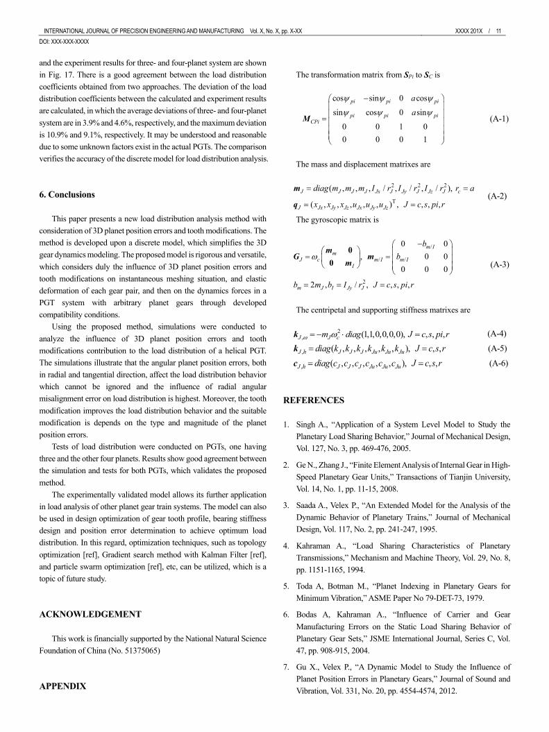
INTERNATIONAL JOURNAL OF PRECISION ENGINEERING AND MANUFACTURING Vol. X, No. X, pp. X-XX XXXX 201X / 11 DOI: XXX-XXX-XXXX
and the experiment results for three- and four-planet system are shown in Fig. 17. There is a good agreement between the load distribution coefficients obtained from two approaches. The deviation of the load distribution coefficients between the calculated and experiment results are calculated, in which the average deviations of three- and four-planet system are in 3.9% and 4.6%, respectively, and the maximum deviation is 10.9% and 9.1%, respectively. It may be understood and reasonable due to some unknown factors exist in the actual PGTs. The comparison verifies the accuracy of the discrete model for load distribution analysis. 6. Conclusions
This paper presents a new load distribution analysis method with consideration of 3D planet position errors and tooth modifications. The method is developed upon a discrete model, which simplifies the 3D gear dynamics modeling. The proposed model is rigorous and versatile, which considers duly the influence of 3D planet position errors and tooth modifications on instantaneous meshing situation, and elastic deformation of each gear pair, and then on the dynamics forces in a PGT system with arbitrary planet gears through developed compatibility conditions.
Using the proposed method, simulations were conducted to analyze the influence of 3D planet position errors and tooth modifications contribution to the load distribution of a helical PGT. The simulations illustrate that the angular planet position errors, both in radial and tangential direction, affect the load distribution behavior which cannot be ignored and the influence of radial angular misalignment error on load distribution is highest. Moreover, the tooth modification improves the load distribution behavior and the suitable modification is depends on the type and magnitude of the planet position errors.
Tests of load distribution were conducted on PGTs, one having three and the other four planets. Results show good agreement between the simulation and tests for both PGTs, which validates the proposed method.
The experimentally validated model allows its further application in load analysis of other planet gear train systems. The model can also be used in design optimization of gear tooth profile, bearing stiffness design and position error determination to achieve optimum load distribution. In this regard, optimization techniques, such as topology optimization [ref], Gradient search method with Kalman Filter [ref], and particle swarm optimization [ref], etc, can be utilized, which is a topic of future study.
ACKNOWLEDGEMENT
This work is financially supported by the National Natural Science Foundation of China (No. 51375065) APPENDIX
The transformation matrix from SPi to SC is
(A-1)
The mass and displacement matrixes are
(A-2)
The gyroscopic matrix is
(A-3)
The centripetal and supporting stiffness matrixes are
(A-4)
(A-5)
(A-6)
REFERENCES 1. Singh A., “Application of a System Level Model to Study the
Planetary Load Sharing Behavior,” Journal of Mechanical Design, Vol. 127, No. 3, pp. 469-476, 2005.
2. Ge N., Zhang J., “Finite Element Analysis of Internal Gear in High-Speed Planetary Gear Units,” Transactions of Tianjin University, Vol. 14, No. 1, pp. 11-15, 2008.
3. Saada A., Velex P., “An Extended Model for the Analysis of the Dynamic Behavior of Planetary Trains,” Journal of Mechanical Design, Vol. 117, No. 2, pp. 241-247, 1995.
4. Kahraman A., “Load Sharing Characteristics of Planetary Transmissions,” Mechanism and Machine Theory, Vol. 29, No. 8, pp. 1151-1165, 1994.
5. Toda A, Botman M., “Planet Indexing in Planetary Gears for Minimum Vibration,” ASME Paper No 79-DET-73, 1979.
6. Bodas A, Kahraman A., “Influence of Carrier and Gear Manufacturing Errors on the Static Load Sharing Behavior of Planetary Gear Sets,” JSME International Journal, Series C, Vol. 47, pp. 908-915, 2004.
7. Gu X., Velex P., “A Dynamic Model to Study the Influence of Planet Position Errors in Planetary Gears,” Journal of Sound and Vibration, Vol. 331, No. 20, pp. 4554-4574, 2012.
cos sin 0 cos
sin cos 0 sin
0 0 1 00 0 0 1
pi pi pi
pi pi pCP
ii
a
a
y y y
y y y
-æ öç ÷ç ÷= ç ÷ç ÷ç ÷è ø
M
2 2 2
T
( , , , / , / , / ),
( , , , , , ) , , , ,J J J Jx J Jy J Jz J c
J Jx Jy Jz Jx z
J
Jy J
diag m m m I r I r I r r a
Jx x x u u u c s pi r
= =
= =q
m
/
/ /
2
0 0, 0 0
0 0 0
,2 , / , ,,
m Im
c m I m II
m J I Jy J
J
J
bb
b m cr rI s pb i
w-æ ö
æ ö ç ÷= =ç ÷ ç ÷è ø ç ÷è ø
== =
mG m
m0
0
2, (1,1,0,0,0,0 , , , ,) J J cm di J c s p rag iw w= - × =k
, ( , , , , , , ,), J J J Ju Ju JuJ h diag k k k k sk J c rk= =k
, ( , , , , , , ,), J J J Ju Ju JuJ h diag c c c c sc J c rc= =c

12 / XXXX 201X INTERNATIONAL JOURNAL OF PRECISION ENGINEERING AND MANUFACTURING Vol. X, No.X 8. Singh A., “Load Sharing Behavior in Epicyclic Gears: Physical
Explanation and Generalized Formulation,” Mechanism and Machine Theory, Vol. 45, pp. 511-530, 2010.
9. Singh A., “Application of a System Level Model to Study the Planetary Load Sharing Behavior,” Journal of Mechanical Design, Vol. 127, pp. 469-476, 2005.
10. Dong H., Wu Y., Wang D., Bai S., “M-DOF Dynamic Model for Load Sharing Behavior Analysis of PGT,” Journal of Mechanical Science and Technology, Vol. 30, No. 3, pp. 993-1001, 2016.
11. Hu Y., Talbot D., Kahraman A., “A Load Distribution Model for Planetary Gear Sets,” Journal of Mechanical Design, Vol. 140, pp. 1-14, 2018.
12. Ren F., Qing D., Lim T.C., “Study on Dynamic Characteristics and Load Sharing of a Herringbone Planetary Gear with Manufacturing Errors,” International Journal of Precision Engineering and Manufacturing, Vol. 15, No. 9, pp. 1925-1934, 2014.
13. Kim J.-G, Park Y.-J, Lee S.-D, Kim J.-H, “Influence of the Carrier Pinhole Position Errors on the Load Sharing of a Planetary Gear Train,” International Journal of Precision Engineering and Manufacturing, Vol. 19, No. 4, pp. 537-543, 2018.
14. Park Y., Lee G., Oh J., et al., “Effects of Non-torque Loads and Carrier Pinhole Position Errors on Planet Load Sharing of Wind Turbine Gearbox,” International Journal of Precision Engineering and Manufacturing-Green Technology, Vol. 6, No. 2, pp. 281-292, 2019.
15. Cao Z., Shao Y., Zuo MJ., et al., “Dynamic and Quasi-Static Modeling of Planetary Gear Set Considering Carrier Misalignment Error and Varying Line of Action along Tooth Width,” Proc IMech Part C: J Mechanical Engineering Science, Vol. 229, No. 8, pp. 1348-1360, 2015.
16. Abousleiman V., Velex P., “A Hybrid 3D Finite Element/Lumped Parameter Model for Quasi-Static and Dynamic Analyses of Planetary/Epicyclic Gear Sets,” Mechanism and Machine Theory, Vol. 41, No. 6, pp. 725-748, 2006.
17. Zhang J., Song Y., Wang J., “Dynamic Modeling for Spur Planetary Gear Transmission with Flexible Ring Gear,” Journal of Mechanical Engineering, Vol. 45, No. 12, pp. 29-36, 2009.
18. Ligata H., Kahraman A., Singh A., “An Experimental Study of the Influence of Manufacturing Errors on the Planetary Gear Stresses and Planet Load Sharing,” Journal of Mechanical Design, Vol. 130, No. 4, pp. 137-139, 2008..
19. Kim J.-G, Park Y.-J, Lee G.-H, et al., “An Experimental Study on the Effect of Carrier Pinhole Position Errors on Planet Gear Load Sharing,” International Journal of Precision Engineering and Manufacturing, Vol. 17, No.10, pp. 1305-1312, 2016.
20. Kim J.-G, Park Y.-J, Lee G.-H, et al., “Experimental Study on the Carrier Pinhole Position Error Affecting Dynamic Load Sharing of Planetary Gearboxes,” International Journal of Precision Engineering and Manufacturing, Vol. 19, No.6, pp. 881-887, 2018.
21. Litvin F. L., Vecchiato D., Demenego A., et al., “Design of One Stage Planetary Gear Train with Improved Conditions of Load Distribution and Reduced Transmission Errors,” Journal of Mechanical Design, Vol. 124, No. 4, pp. 745-752, 2002.
22. Mohamad E., Komori M., Murakami H., et al., “Analysis of General Characteristics of Transmission Error of Gears with Convex Modification of Tooth Flank Form Considering Elastic Deformation under Load,” Journal of Mechanical Design, Vol. 13, No. 6, pp. 2751-2764, 2009.
23. Oh S., Oh S., Kang J., “A Study on Modeling and Optimization of Tooth Microgeometry for a Helical Gear Pair,” International Journal of Precision Engineering and Manufacturing, Vol. 14, No. 3, pp. 423-427, 2013.
24. Kim J., Park N., Lee H., “Tooth Modification for Optimizing Gear Contact of a Wind-Turbine Gearbox,” Proc IMech Part C: J Mechanical Engineering Science, Vol. 230, No. 7, pp. 1318-1330, 2016.
25. Wang Q., Zhang Y., “A Model for Analyzing Stiffness and Stress in a Helical Gear Pair with Tooth Profile Errors,” Journal of Vibration and Control, Vol. 23, No. 10, pp. 272-289, 2015.
26. Liang X., Zuo M., Guo Y., “Evaluating the Time-Varying Mesh Stiffness of a Planetary Gear Set Using the Potential Energy Method,” Proc IMech Part C: J Mechanical Engineering Science, Vol. 228, No. 3, pp. 535-547, 2014.
27. Zhou C., Chen C., Gui L., et al., “A Nonlinear Multi-Point Meshing Model of Spur Gears for Determining the Face Load Factor,” Mechanism and Machine Theory, Vol. 126, pp. 210-224, 2018.