Modeling - abl.gtu.edu.trabl.gtu.edu.tr/hebe/AblDrive/70976026/w/Storage/102_2010_2_322... · Back...
40
Modeling This lecture we will consentrate on how to do system modeling based on two commonly used techniques – In frequency domain using Transfer Function (TF) representation – In time domain via using State Space representation Transition between the TF to SS and SS to TF will also be discussed.
Transcript of Modeling - abl.gtu.edu.trabl.gtu.edu.tr/hebe/AblDrive/70976026/w/Storage/102_2010_2_322... · Back...

Modeling
This lecture we will consentrate on how to do system modeling based on two commonly used techniques
– In frequency domain using Transfer Function (TF) representation
– In time domain via using State Space representation
Transition between the TF to SS and SS to TF will also be discussed.

Transfer Function Representation
Transfer functions is an Input/Output approach for system modelling
In Laplace Domain this becomes
whereRelating the output to the input is called the transfer function of the system

Transfer Function (TF)
For the differential equation of the form
the transfer function is
Note that transfer function is obtained by assuming that all the initial conditions are zero
Roots of the numerator of are the zeros of
Roots of the denominator of are the poles of
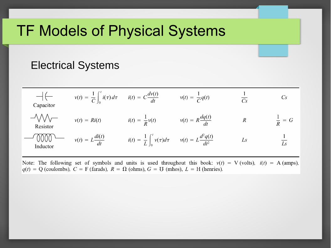
TF Models of Physical Systems
Electrical Systems

Electrical Systems
Back to the basic example of RLC circuit
Time Domain Laplace Domain

Electrical System
After some mathematical manipulatons
That is

2-Loop Electrical System
Find the relation between the input voltage and the voltage across the capacitor

2-Loop Electrical System
System in Laplace domain
(1)
(2)

2-Loop Electrical System
Solve for with respect to from the mesh equation (1) and replace it in the output equation (2)
Transfer function is then

Important Note
Becarefull
The approach :
Loop1 Loop2
will not work... WHY ??

3-loop example
Find the input output realtion for the given circuit

3-loop electrical system
Mesh equation :
Output equation :
Solve the mesh equation for then insert it in the output equation

Mechanical Systems

Mechanical Systems

Mechanical System Example
An easy mass spring damper system
Time domain
Laplace (frequency) domain

Mechanical Systems
Find the input output relationship of the system
EOM (equations of motion) in s-domain
(1)
(2)

Mechanical Systems
Use (1) to find a realtionship between and
Then insert this into (2) to obtain
The transfer function is then
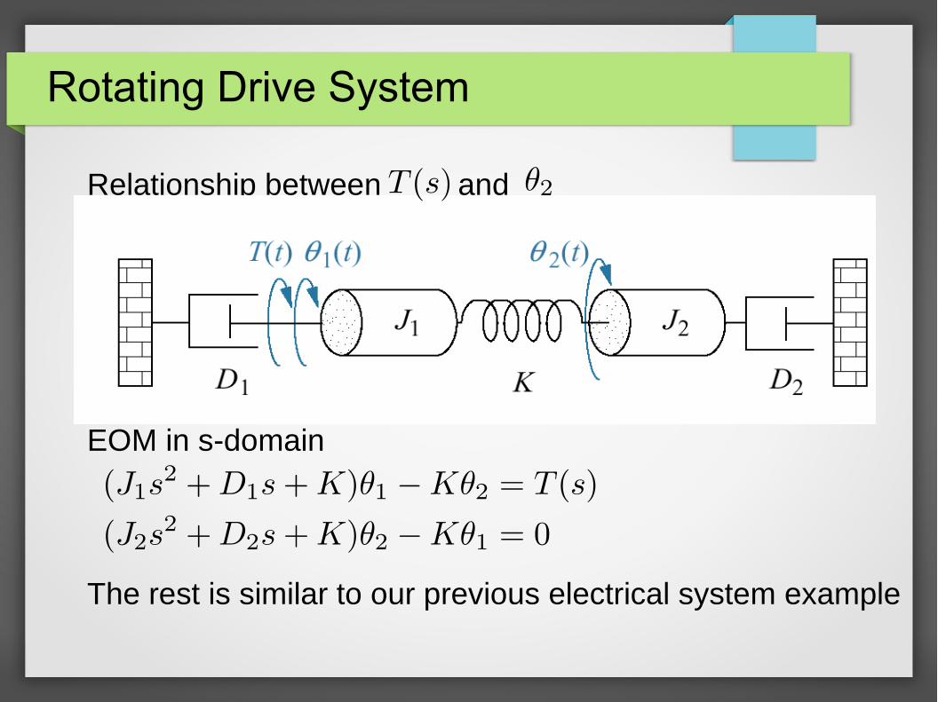
Rotating Drive System
Relationship between and
EOM in s-domain
The rest is similar to our previous electrical system example

Electromechanical System
DC motor, relationship between input voltage and motor's rotational position
Note that:

Electromechanical System
The EOM of the system in s-domain
inserting for the voltage across the motor and the motor torque
Rest is mathematical manipulations

State Space Representation
We start with a similar example
The differential equation representing the system is
and the system output is the position
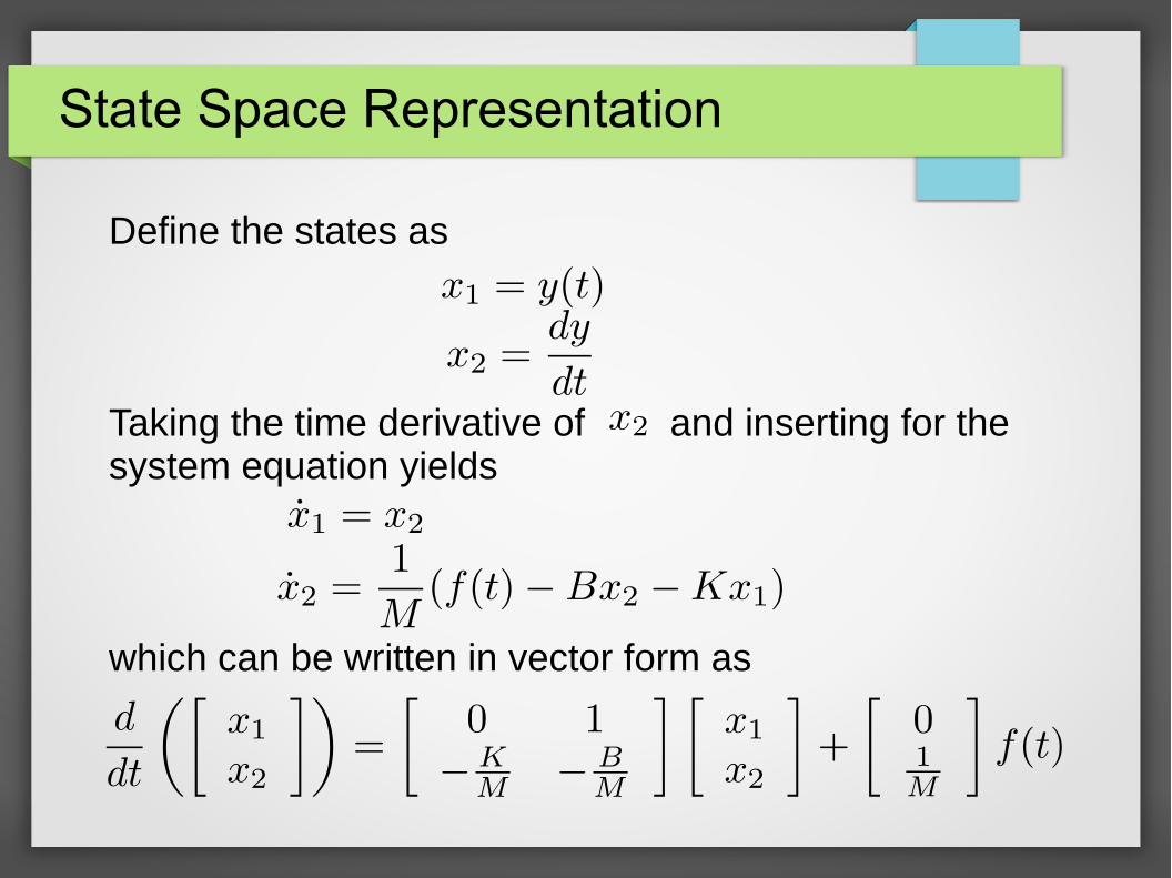
State Space Representation
Define the states as
Taking the time derivative of and inserting for the system equation yields
which can be written in vector form as
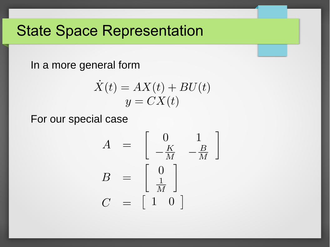
State Space Representation
In a more general form
For our special case
So What ?
What have we gained ?
– We were able to represent a high order scalar differential equation with a first order, but in matrix form, differential eqaution.
– Solution should be much more easier but requires linear algebra knowledge as well.
Can we somehow go back to Transfer function representation ?
– Lets give a try
Converting from SS to TF
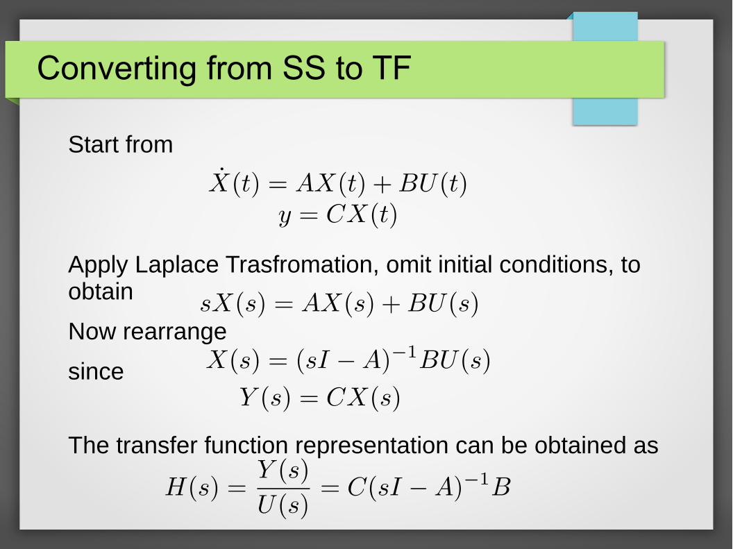
Start from
Apply Laplace Trasfromation, omit initial conditions, to obtain
Now rearrange
since
The transfer function representation can be obtained as
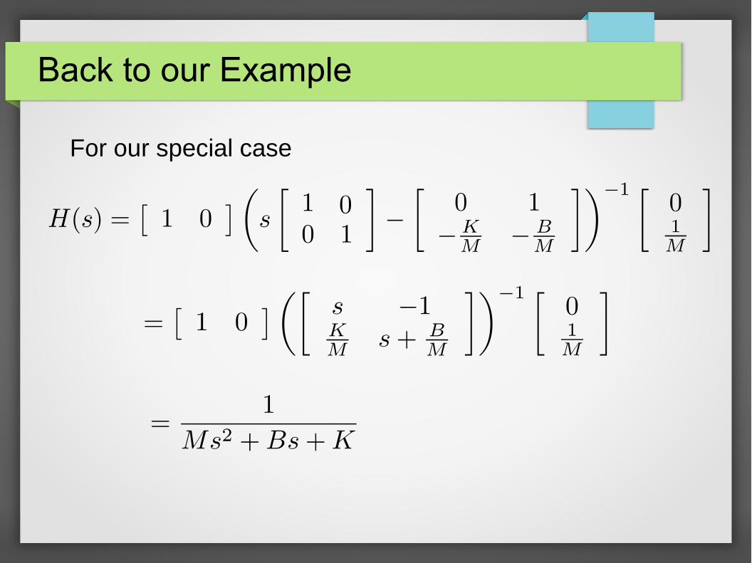
Back to our Example
For our special case

Converting from TF to SS *
Consider the transfer function of the form
which is assumed to be strictly proper. That is
Rearrange the transfer function to have the following form
V 's are the states
where
: State Eq
: Output Eq

Converting from TF to SS
This enables us to write the matrix eqaution
and the output equation as

Example
Consider the case n = 3
then
In matrix form
Block Diagram Representation
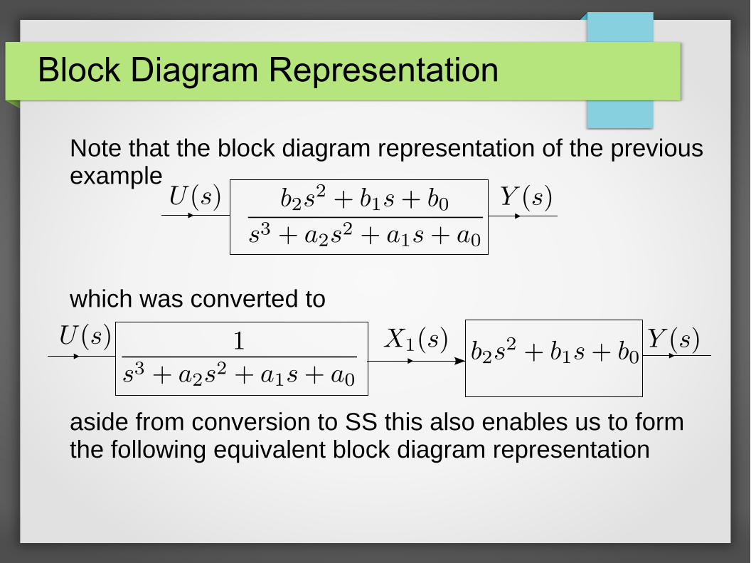
Note that the block diagram representation of the previous example
which was converted to
aside from conversion to SS this also enables us to form the following equivalent block diagram representation

Block Diagram Representation

Solution of State Equations
(1) Solution by Laplace Transform
start from
Using Laplace Transform obtain
where
is called Resolvent Matrix
is the State Transition Matrix

Solution of State Equations
Observe that
and since
we can rewrite the solution for as follows

Example
Consider the system of the form
calculate the output response to unit step input when the initial conditions are given as
Example
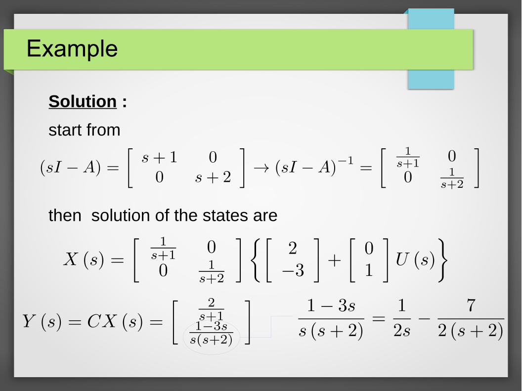
Solution :
start from
then solution of the states are

Example (cont.)
Taking inverse Laplace Transform yields
Alternatively,
Then we can directly calculate
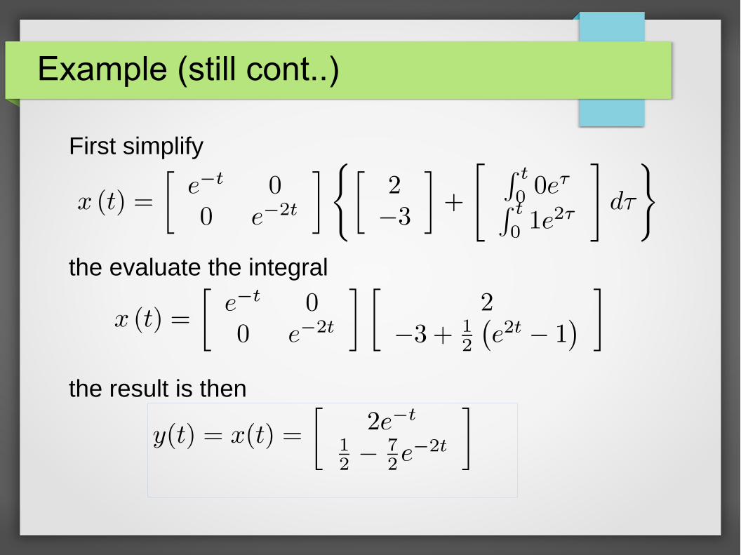
Example (still cont..)
First simplify
the evaluate the integral
the result is then

Solution of State Equations
(2) Formal (Classical) Solution of State Equation
Take the scalar case
rearrange to have
multiply both sides by
integrate both sides

Solution of State Equations
Multiply each side by to obtain
which in matrix form would have been
or

State Transition Matrix
Some of the usefull Properties of the State Transition Matrix
1 .
2.
as
3.
as