MODELING A MULTISOURCE ENERGY SYSTEM FOR AN …
116
ECOLE D’INGENIEURS-ES GÉNÉRALISTES RESEARCH INSTITUTE INTERNSHIP REPORT DEGREE IN ELECTRICAL ENGINEERING MODELING A MULTISOURCE ENERGY SYSTEM FOR AN ELECTRIC VEHICLE Author: Tutor: Laura Barajas Martínez Kambiz Tehrani Rouen, June 2018
Transcript of MODELING A MULTISOURCE ENERGY SYSTEM FOR AN …

ECOLE D’INGENIEURS-ES GÉNÉRALISTES RESEARCH INSTITUTE
INTERNSHIP REPORT
DEGREE IN ELECTRICAL ENGINEERING
MODELING A MULTISOURCE
ENERGY SYSTEM FOR AN
ELECTRIC VEHICLE
Author: Tutor:
Laura Barajas Martínez Kambiz Tehrani
Rouen, June 2018

2 MODELING A MULTISOURCE ENERGY SYSTEM FOR AN ELECTRIC VEHICLE

3 MODELING A MULTISOURCE ENERGY SYSTEM FOR AN ELECTRIC VEHICLE
ABSTRACT
Over the last few years Electric and Hybrid Electric vehicles (EVs and HEVs) have been in
full apogee in the automotive industry. They have evolved a lot making people’s life
easier and also as a solution to deal with global warming due to the reduction of CO2
emissions, the local pollution and consequently, the noise pollution making a cleaner
and greener environment.
Although scientists, researches and engineers have developed a lot of technologies to
improve the conventional vehicles by making Electric and Hybrid vehicles, they are still
searching new solutions to improve their performance.
These new improvements have made people more aware about buying this type of cars
instead of the Internal combustion engine ones due to their efficiency, reliability, lower
consumption and of course, because they are environmentally friendly.
This project allows the reader, whether specialized or not in the subject, to have a global
vision of the operation of the electric vehicle, their components, their advantages and
disadvantages and finally, it also facilitates the reader to understand the operation of
the new technologies applied to the electric vehicle such as V2G (Vehicle-to-Grid), V2B
(Vehicle-to-Building) and VTH (Vehicle-to-Home).
In addition, the project explains in detail the use of the different energy storage systems
in the electric vehicle such as batteries, supercapacitors and fuel cells, as well as the
operation of each one of them and the advantages and disadvantages between them.
Moreover, the modelling of these energy storage systems is also shown in the paper.
After that, some simulations of the energy storage systems are represented in PSIM.
Finally, we suggest an application for the EV which consist in increase the number of
energy storage systems in order to improve its efficiency while driving, so we propose a
hybrid energy storage system for the EV. Moreover, an explanation about how the
energy stored into these devices could be injected into the electrical grid for provide
more energy while the car is not being used is given.
Furthermore, this project has a double purpose: on one hand, to advance in the fields
of work that will be the basis of the future, such as research, and on the other, it has a
didactic purpose, demonstrating the readers and future students the developments in
the new technologies that are applied to electric vehicles.
KEYWORDS Electric Vehicle (EV), Energy Storage System (ESS), Hybrid Energy Storage System (HESS),
Vehicle-to-grid (V2G), Vehicle-to-home (V2H), Vehicle-to-building (V2B), battery,
supercapacitor, fuel-cell, power grid, photovoltaic system, modelling of ESS.

4 MODELING A MULTISOURCE ENERGY SYSTEM FOR AN ELECTRIC VEHICLE
RÉSUMÉ
Les véhicules électriques et hybrides (VE et VEH), en tant que solution d’avenir contre
réchauffement climatique, se sont massivement développés ces dernières années.
Si les activités de R&D ont permis l’amélioration des véhicules conventionnels, les
chercheurs et les ingénieurs sont toujours à la recherche de nouvelles solutions
techniques destinées à améliorer la performance des véhicules électriques et hybrides.
Ces nouvelles améliorations, vulgarisées par de nombreuses actions de communication
notamment de la part des pouvoirs publics, ont incité les consommateurs à se tourner
vers les véhicules moins polluants, au lieu de celles à moteur à combustion interne, en
raison de leur efficacité, leur fiabilité, leur faible consommation et, bien sûr, parce
qu'elles sont respectueuses de l'environnement.
Ce projet permet au lecteur, spécialisé ou non, d'avoir une vision globale du
fonctionnement du véhicule électrique, de ses composants, de ses avantages et de ses
inconvénients. Il facilite également la compréhension du fonctionnement des nouvelles
technologies appliquées au véhicule électrique telles que V2G (véhicule vers réseau),
V2B (véhicule vers bâtiment) et VTH (véhicule vers domicile).
En outre, le projet explique en détail l'utilisation des différents systèmes de stockage
d'énergie dans le véhicule électrique tels que les batteries, les supercondensateurs et
les piles à combustible, ainsi que le fonctionnement de chacun d'entre eux, à travers
une analyse comparative. La modélisation des différents systèmes de stockage
d'énergie est également présentée dans ce projet. Certaines simulations font l’objet
d’une modélisation sous PSIM.
Enfin, nous proposons une application pour le EV qui consiste à augmenter le nombre
de systèmes de stockage d'énergie afin d'améliorer son efficacité pendant la conduite.
De plus, nous expliquons comment l'énergie stockée dans ces dispositifs pourrait être
injectée dans le réseau électrique pour fournir plus d'énergie.
Ce projet a un double objectif : d'une part, établir un état de l’art pouvant aboutir à un
futur travail de recherche, et d'autre part, illustrer, et ce, dans un but didactique, le
développement des nouvelles technologies appliquées aux véhicules électriques.
MOTS CLÉS Véhicule électrique (EV), Système de stockage d'énergie (ESS), Système de stockage
d'énergie hybride (HESS), V2G, V2H, V2H, V2B, batterie, supercondensateur, pile à
combustible, réseau électrique, système photovoltaïque, modélisation de l'ESS.

5 MODELING A MULTISOURCE ENERGY SYSTEM FOR AN ELECTRIC VEHICLE
TABLE OF CONTENTS
CHAPTER 1
1. INTRODUCTION, ORGANIZATION AND OBJECTIVES ................................ 13
1.1 INTRODUCTION .............................................................................................. 13
1.2 ORGANIZATION OF THE DOCUMENT ............................................................ 15
1.3 OBJECTIVES .................................................................................................... 16
2. HOW DOES AN ELECTRIC VEHICLE WORK? ........................................ 18
2.1 HISTORY OF THE ELECTRIC VEHICLE .............................................................. 18
2.2 OPERATING PRINCIPLE ................................................................................... 18
2.3 DIFFERENT MODES OF RECHARGE OF ELECTRIC VEHICLE ............................. 19
2.4 COMPONENTS OF AN ELECTRIC VEHICLE ...................................................... 22
2.4.1 CHARGER .................................................................................................... 22 2.4.2 CONVERTERS .............................................................................................. 23
2.4.2.1 DC-DC Converters................................................................................. 24 2.4.2.2 DC-AC Conversion: Inversion ............................................................... 25 2.4.2.3 AC-DC Conversion: Rectification .......................................................... 26 2.4.2.4 AC-AC Conversion ................................................................................ 26
2.4.3 TYPES OF ELECTRIC MOTORS ...................................................................... 27
2.4.3.1 Asynchronous ...................................................................................... 29 2.4.3.2 Synchronous ........................................................................................ 29 2.4.3.3 Switched reluctance ............................................................................ 29
2.4.3.4 Brushless ..................................................................................... 30
2.4.4 CONTROLLER............................................................................................... 30
2.4.5 ENERGY STORAGE SYSTEMS .................................................................. 31
2.5 ADVANTAGES AND DISADVANTAGES OF USING EVs .................................... 31
3. STATE OF THE ART ............................................................................ 32
3.1 VEHICLE-TO-GRID (V2G)................................................................................. 32
3.2 VEHICLE-TO-BUILDING (V2B) ......................................................................... 34
3.3 VEHICLE-TO-HOME (V2H) .............................................................................. 34

6 MODELING A MULTISOURCE ENERGY SYSTEM FOR AN ELECTRIC VEHICLE
CHAPTER 2
4. ENERGY STORAGE SYSTEMS FOR AN ELECTRIC VEHICLE .................... 37
4.1 BATTTERIES .................................................................................................... 37
4.1.1 Lead-Acid batteries ..................................................................................... 40 4.1.2 Lithium-ion batteries .................................................................................. 40 4.1.3 Nickel Metal Hydride batteries ................................................................... 41 4.1.4 Battery Management System for Electric Vehicles .................................... 41 4.1.5 Table comparative of different types of batteries ................................ 42-43
4.2 SUPERCAPACITORS ........................................................................................ 44
4.3 FUEL-CELLS ..................................................................................................... 47
4.4 TABLE COMPARATIVE OF ENERGY STORAGE SYSTEMS ................................. 51
5. MODELLING OF THE ENERGY STORAGE SYSTEMS ............................. 53
5.1 MODELLING OF BATTTERIES .......................................................................... 53
5.1.1 Modelling of Lead-Acid batteries ............................................................... 53 5.1.2 Modelling of Lithium-ion batteries ............................................................. 60 5.1.3 Modelling of Nickel Metal Hydride batteries ............................................. 66
5.2 MODELLING OF SUPERCAPACITORS .............................................................. 71
5.3 MODELLING OF FUEL-CELLS ........................................................................... 74
CHAPTER 3
6. PHOTOVOLTAIC SYSTEMS FOR ELECTRIC VEHICLE ............................. 78
6.1 HOW TO INSTALL SOLAR PANELS IN EVs ....................................................... 78
6.2 MODELLING OF A PHOTOVOLTAIC SYSTEM .................................................. 81
CHAPTER 4
7. SIMULATION RESULTS ...................................................................... 89
7 MODELING A MULTISOURCE ENERGY SYSTEM FOR AN ELECTRIC VEHICLE
CHAPTER 5
8. ELECTRIC VEHICLE WITH HYBRID ESS ................................................ 94
9. CONNECTION BETWEEN THE CAR AND THE GRID (V2G) .................... 97
CONCLUSIONS & FUTURE RESEARCH ................................................... 103
TECHNICAL ASSESSMENT .................................................................... 108
PERSONAL ASSESSMENT ..................................................................... 108
PERSPECTIVES ..................................................................................... 109
REFERENCES ........................................................................................ 110
8 MODELING A MULTISOURCE ENERGY SYSTEM FOR AN ELECTRIC VEHICLE
TABLE OF FIGURES Figure 1: CO2 Emissions by Sector in 2014 .......................................................................... 13
Figure 2: First electric car in the 19th century ..................................................................... 18
Figure 3: Induction charging system ................................................................................... 20
Figure 4: Elements of electric car ........................................................................................ 22
Figure 5: Charger of an EV .................................................................................................. 22
Figure 6: Adjustable speed motor drive .............................................................................. 23
Figure 7: Buck converter .................................................................................................... 24
Figure 8: Boost converter ................................................................................................... 25
Figure 9: Electric engine of an EV ........................................................................................ 27
Figure 10: Basic electric vehicle propulsion system ............................................................. 27
Figure 11: Asynchronous engine ......................................................................................... 29
Figure 12: Synchronous engine ........................................................................................... 29
Figure 13: Switched reluctance engine ............................................................................... 29
Figure 14: Permanent magnet engine ................................................................................. 30
Figure 15: Controller of an EV ............................................................................................. 30
Figure 16: Wireless control connections between vehicles and electric power grid .............. 33
Figure 17: Representation of a battery ............................................................................... 37
Figure 18: (a) arrangement of Lithium-ion battery in EV / (b) Battery pack .......................... 40
Figure 19: Schematic structure of BMS ............................................................................... 41
Figure 20: Schematic of an individual Fuel-Cell ................................................................... 47
Figure 21: PEM Fuel-Cell .................................................................................................... 49
Figure 22: Thevenin Lead-acid battery model ..................................................................... 53
Figure 23: Lead-acid battery equivalent circuit ................................................................... 54
Figure 24: Equivalent circuit of short-term Thevenin-discharge lead-acid battery model ...... 56
Figure 25: Equivalent circuit of the long-term integrated lead-acid battery model ............... 56
Figure 26: Simple electrical lead-acid battery model ........................................................... 57
Figure 27: Proposed linear electrical lead-acid battery model ............................................. 58
Figure 28: Overvoltage part of lead-acid battery model ...................................................... 59
Figure 29: Dynamic model for a lead-acid battery ............................................................... 59
Figure 30: Lineal model of a battery ................................................................................... 60
Figure 31: Equivalent Thevenin model ............................................................................... 60

9 MODELING A MULTISOURCE ENERGY SYSTEM FOR AN ELECTRIC VEHICLE
Figure 32: Proposed electrical battery model ...................................................................... 61
Figure 33: Proposed battery pack equivalent circuit ............................................................ 63
Figure 34: Battery pack electric circuit ................................................................................ 65
Figure 35: Equivalent electric scheme of a single 1.2V 13.5Ah Ni-MH cell ............................ 66
Figure 36: Warburg impedance under the form of n RC networks........................................ 67
Figure 37: Energetic model of a single Ni-MH cell ................................................................ 68
Figure 38: Basic Ni-MH battery model ................................................................................ 69
Figure 39: Equivalent circuit model for Ni-MH battery ........................................................ 70
Figure 40: Supercapacitor circuit RC model ........................................................................ 71
Figure 41: Classical equivalent circuit of an EDLC ............................................................... 71
Figure 42: Equivalent circuit model for a DLC ...................................................................... 72
Figure 43: Ultracapacitor equivalent circuit ....................................................................... 74
Figure 44: Equivalent dynamic circuit model of a PEM fuel cell ............................................ 75
Figure 45: Small signal equivalent circuit model of PEM fuel cell ......................................... 76
Figure 46: Design of solar powered EV charging station ...................................................... 46
Figure 47: Installation of solar panels on the roof of an EV .................................................. 79
Figure 48: Equivalent electrical circuit of a solar cell ........................................................... 82
Figure 49: PV system connected with boost converter ....................................................... 82
Figure 50: Model of GCPS ................................................................................................... 83
Figure 51: Equivalent circuit of a PV module ....................................................................... 84
Figure 52: EV charging/discharging: H2V2H structure .......................................................... 85
Figure 53: Equivalent circuit of a solar cell .......................................................................... 86
Figure 54: DC-DC charger topologies (a) Boost / (b) Buck-boost ........................................... 87
Figure 55: Schematic of a multisource energy system for simulation ................................... 89
Figure 56: Multisource energy system in software PSIM ..................................................... 90
Figure 57: Three-phase inverter ......................................................................................... 90
Figure 58: Control via pulse width modulation (PWM) for 3-phase inverter ......................... 91
Figure 59: Supercapacitor .................................................................................................. 91
Figure 60: Battery DC ......................................................................................................... 91
Figure 61: Representation of current I charge ..................................................................... 92
Figure 62: Representation of Voltage V charge ................................................................... 92

10 MODELING A MULTISOURCE ENERGY SYSTEM FOR AN ELECTRIC VEHICLE
Figure 63: Fuel-cell –battery- supercapacitor hybrid electric vehicle .................................... 95
Figure 64: Fuel cell- battery-supercapacitor equivalent circuits ........................................... 95
Figure 65: Representation of a Smart Grid .......................................................................... 99
Figure 66: Representation of a Micro Grid .......................................................................... 99
Figure 67: Users can receive power .................................................................................. 100
Figure 68: Representation of a Micro Grid ........................................................................ 101
Figure 69: Representation of the application V2G ............................................................. 101
Figure 70: Graphene’s hexagonal, thin structure .............................................................. 104
Figure 71: Recharge in motion ......................................................................................... 105
Figure 72: On-road charging system for charging-while-driving ......................................... 106
INDEX OF TABLES Table 1: Comparison of different types of motors ................................................... 28
Table 2: Advantages and disadvantages of using EVs............................................... 31
Table 3: Table comparative of batteries for EVs ................................................. 42-43
Table 4: Differences between capacitor and supercapacitor .................................... 45
Table 5: Different types of supercapacitors ............................................................. 46
Table 6: Different types of Fuel-Cells ....................................................................... 48
Table 7: Table comparative of Energy Storage Systems ...................................... 51-52

11 MODELING A MULTISOURCE ENERGY SYSTEM FOR AN ELECTRIC VEHICLE

12 MODELING A MULTISOURCE ENERGY SYSTEM FOR AN ELECTRIC VEHICLE
CHAPTER 1 1. INTRODUCTION, ORGANIZATION AND OBJECTIVES
2. HOW DOES AN ELECTRICAL VEHICLE WORK?
3. STATE OF THE ART

13 MODELING A MULTISOURCE ENERGY SYSTEM FOR AN ELECTRIC VEHICLE
1. INTRODUCTION, ORGANIZATION AND OBJECTIVES
1.1 INTRODUCTION
In the last few years, a lot of countries are trying to reduce the consumption of fossil
fuels in order to diminish the emission of greenhouse gases (GHG) and other pollutants
that are harmful to health and which are responsible for global warming and the climate
change.
The sector of transport is one of the main sources of consumption of fossil fuel. As we
can see in the “Report on World’s CO2 emissions situation”, in 2014 the world CO2
emissions that belonged to the road transport sector were 17,5% [1]. In the following
image we show the CO2 emissions of each sector in 2014 as explained in the report:
Fig 1. CO2 Emissions by Sector in 2014
That is the reason why in recent years’ governments have been encouraging the
implementation of Electric vehicles (EVs) and Hybrid Electric Vehicles (HEVs), especially
in urban environments, in order to reduce the fossil fuel emissions and to contribute
with the environment.
Nowadays, researchers and scientists are searching for solutions to develop and
improve electric vehicles. However, the problem lies in the way of obtaining, storing and
controlling the energy that allows the vehicle to function properly.
5,7%4,4%
5,8%
17,5%
19,2%5,2%
42,1%
CO2 Emissions by Sector in 2014
Residential
Non residential
Rest of Transport
Road Transport
Manufacturing industries andconstruction
Other energy industry own use
Electricity and heat production
14 MODELING A MULTISOURCE ENERGY SYSTEM FOR AN ELECTRIC VEHICLE
In this project are shown the different energy storage systems (ESS) that exist and which
could be used in the electric vehicle for improving the efficiency in storing energy.
The structure and the functioning of these energy storage systems are studied in depth.
This process entails the use of chemical knowledge, related to the chemical compounds
and how they react to each other and also it is necessary to have some energetic and
electrical knowledge for understanding the balance and management of the electricity
in these devices.
Moreover, throughout the paper, the different types of modelling of the different
energy storage systems such as batteries, supercapacitors and fuel cells will be shown,
in order to obtain their equivalent electric circuits.
The search for the equivalent model of a battery, a supercapacitor or a fuel cell, aims to
reproduce its behaviour.
Thus, the project collects and exposes the differences of the equivalent models of the
energy storage systems. To do this, an in-depth analysis of a series of articles and studies
carried out over the last few years by different researchers from around the world has
been done. These researchers have been comparing the different options for modelling
these systems and explaining the different methods for the identification of the
parameters of each model. As a result, they have obtained a series of conclusions.
As a source of compilation of the articles we have used the interactive library of the
scientific journal IEEE and other articles found in other research platforms. The articles
consulted are shown in the bibliography section.
Once the equivalent models of the energy storage systems mentioned above have been
analysed, one of them is proposed for modelling it by means of a simulation software in
order to observe its behaviour. In our case, we have used PSIM.
After we have modelled the system, we suggest an application for the Electric Vehicle
which consists in increasing the number of energy storage sources in order to improve
its efficiency while driving. Moreover, an explanation about how the energy stored into
these devices could be injected into the electrical grid for providing more energy while
the car is not being used is given.
Furthermore, as an incentive for possible future work in this field of application, the use
of graphene in batteries and supercapacitors will be briefly explained. This technology
promises to be the key of the future due to the features it offers when applied into these
systems. Moreover, another application called “recharge in motion” is explained. This
application consists in recharging the batteries of the car while driving across specific
streets and lanes on highways.

15 MODELING A MULTISOURCE ENERGY SYSTEM FOR AN ELECTRIC VEHICLE
Thanks to this project, the student who retakes this work, he/she will do so from a point
of view more advanced and it will also offer him/her more facilities when carrying out a
new project related to the same field of application.
Finally, it is worth mentioning that when doing the research for this project the English
level required to fully comprehend this topic was an additional and unexpected
challenge. To cope with this, extra efforts and time to finish this project as it is shown
here were needed.
1.2 ORGANIZATION OF THE DOCUMENT
In order to make this document easy to read, it has been organized into five chapters,
including a short summary of each one of them which will be explained below.
The Chapter 1, makes an introduction about what is going to be explained throughout
the project. Moreover, the organization of the project and its main objectives will be
briefly shown. This chapter also explains the history of the electric vehicle, its operating
principle, the different modes of recharge, the advantages and disadvantages due to the
usage of an electric vehicle instead of an internal combustion engine and finally, each
one of its components. The state of the art of the latest technologies used in EVs such
as V2G, V2B and VTH is presented.
The Chapter 2 is focused on explaining the three different types of the energy storage
systems that are used in electric vehicles: batteries, supercapacitors and fuel-cells. In
this chapter, all different types of batteries are briefly shown and the three most used
in electric vehicles are explained elaborately. Moreover, the different types of
supercapacitors and fuel cells that are used in EVs are also discussed. At the end of the
chapter, a comparison table of the advantages and disadvantages of the different types
of energy storage systems mentioned above is shown.
Moreover, this chapter also focuses on the modelling of the previous energy storage
systems explained. After extensive research about the electrical equivalent models of
the different energy storage systems presented by many authors, some comparisons are
made between them.
The Chapter 3 explains the implementation of photovoltaic systems in EVs in order to
charge their batteries. Thus, a study to demonstrate the quantity of solar panels that a
building would need to recharge the batteries of an EV which is programmed to make
100 Km of autonomy per day has been made. Finally, the modelling of some
photovoltaic systems are also presented.

16 MODELING A MULTISOURCE ENERGY SYSTEM FOR AN ELECTRIC VEHICLE
The Chapter 4 contains the simulations made in the PSIM software. Thus, a simulation
of the electrical equivalent model of a battery and a supercapacitor is shown. With these
simulations we can observe the behaviour of the performance of the EV with a Hybrid
energy storage system (HESS).
The Chapter 5 explains how to increment the efficiency of the EV by using hybrid energy
storage systems (HESS), which are systems with the combination of two or more ESS.
Moreover, this chapter contains an explanation about how the car is connected into the
electrical grid (V2G application) and how the energy stored into the ESS of the EVs could
be injected into the grid while the car is not being used.
Finally, in the last section of the paper, some conclusions from all the literature made
are explained. This section also represents the new innovations in technology which are
thought to be the future in the manufacturing of Electric and Hybrid Electric vehicles
such as the implementation of the graphene in batteries or supercapacitors and the
technology called “recharge in motion” which consists in recharge the batteries of EVs
while they are driving across specific streets and lanes on highways.
At the end of the document, the references that have been used throughout all the
literature are mentioned.
1.3 OBJECTIVES
This paper contains two main objectives: on one hand, to increase the number of energy
storage systems into EVs in order to improve its autonomy and, on the other, to inject
the energy stored into these devices to the electrical grid for providing more energy
while the car is not being used.
Apart from these main objectives, there are some secondary objectives that have been
proposed throughout the paper:
To know the latest technologies applied into EVs: V2G, V2B and VTH
To know the components that constitutes the Electric vehicle
To understand the performance of an EV
To analyse the advantages and disadvantages of using EVs
To know the different types of ESS that exists
To analyse the modelling of the different ESS
To know how the photovoltaic systems are used in EVs
To analyse the modelling of photovoltaic systems
To understand the Hybrid ESS
To make simulations of Hybrid ESS in PSIM

17 MODELING A MULTISOURCE ENERGY SYSTEM FOR AN ELECTRIC VEHICLE
In line with all subjects mentioned above, this paper is intended to deal with the
following sub-objectives:
Research of specific information about the topic in question
Acquaintance with the technical vocabulary of the subjects studied
Familiarization with research platforms
Research for the different possible ways to model an ESS
Familiarization with the software PSIM
Modelling of the ESS
Research of future innovations in the EV field
Familiarization with bibliographic and research work

18 MODELING A MULTISOURCE ENERGY SYSTEM FOR AN ELECTRIC VEHICLE
2. HOW DOES AN ELECTRICAL VEHICLE WORK?
2.1 HISTORY OF THE ELECTRIC VEHICLE
The electric car was one of the first cars which was developed. In fact, electric vehicles
existed before the diesel and gasoline cars. In the 19th century, between 1832 and 1839,
the Scottish businessman Robert Anderson invented the first electric vehicle.
Fig 2. First electric car in the 19th century
Around the year 1900, the electric cars made remarkable records of speed and distance.
However, there were more improvements made in internal combustion vehicles than in
electric vehicles. So at the end of 1920, the electric car industry disappeared completely,
being relegated to some specific industrial applications such as forklifts.
Finally, in 1996 the electric car appeared again and the most well-known car brands
started to launch a series of EVs [2].
2.2 OPERATING PRINCIPLE
An electric car is a vehicle which is powered by an electrical engine. This engine
transforms the electrical energy provided by the energy storage systems such as
supercapacitors, fuel cells or batteries, into mechanical energy by means of
electromagnetic interactions that occur inside the engine. This way, the electrical energy
is transferred into kinetics and the car can move. Moreover, the car can have a
regenerative braking, so it can convert the mechanical energy while braking into
electrical energy which will be after stored into the ESS for a future use.
So, first of all, it has to charge the energy storage systems. We have two ways of making
the recharge: plug-in it into the network or wirelessly. The charge by means of the
network can be done in garages of houses and buildings or even in public points
19 MODELING A MULTISOURCE ENERGY SYSTEM FOR AN ELECTRIC VEHICLE
scheduled for charging EVs. However, there exist some devices to charge the batteries
wirelessly by means of electromagnetic fields. One of the cars that uses this technology
is the BMW 530e iPerformance as we saw in [3].
We have to know that the time for charging an EV oscillates between 3 and 10 hours, it
depends on the type of the charge and also on the type of the energy storage system
used, because each one has different specifications.
Besides, there are some cars with software applications that are programmed to
manage the charge of the vehicle and as a result, they can take the benefit of using the
electric rate less expensive for charging the ESS. Normally, the rate less expensive is
during the night.
We can also substitute the batteries when they are expired. With this method, the
battery completely wasted is substituted to another which is new and full charged. This
operation takes less time than a full recharge but is more expensive.
2.3 DIFFERENT MODES OF RECHARGE FOR ELECTRIC VEHICLES
Nowadays we have two ways of charging EVs: plug-in them into the network or
wirelessly.
The wirelessly or induction charging system consists basically of two elements: a
transmitter coil and a receiver coil which is located into the vehicle. A coil is a cable
wound up a certain number of times and with a specific thickness. Depending on these
parameters, and the type of material that exists inside, we will have an inductance value.
The operation of this system is based on the Faraday physical principle of induction
which consists in the generation of an electromagnetic field through the passage of an
alternating current through the primary coil (transmitter, situated in the wireless
charging station). This magnetic field will be transmitted to the secondary coil (receiver,
situated into the vehicle) inducing an electric current in it without prior physical contact.
To increase the power, we have to try that the distance between the coils is as small as
possible, that the inductance is as large as possible and that the number of turns of the
coils is identical so that they can enter into resonance [4].
According to Faraday's law:
𝜀 = −𝑁∆∅
∆𝑡
Where:
𝑁: Number of loops ∆𝑡 : Change in time
∆∅: Change in magnetic flux 𝜀 : Voltage induced in Receive coil (emf)

20 MODELING A MULTISOURCE ENERGY SYSTEM FOR AN ELECTRIC VEHICLE
In the following image we show the performance of the induction charging system:
Fig. 3 Induction charging system
Furthermore, the second type of recharge is the recharge by means of the connection
to the network and it can be done in garages of houses and buildings or even in public
points scheduled for charging EVs.
There are different types of plug-in recharge depending on the loading speed and also
depending on the place of the load point.
On one hand, depending on the loading speed, we can differentiate three types of
recharge: conventional recharge (until 16A 3,7kW), semi-fast recharge (until 32A 7,4kW)
and fast recharge (from 32A), this always depends on the voltage and amperage of the
charging point.
CONVENTIONAL RECHARGING
Conventional recharging applies different power levels that involve a charge lasting
approximately 8 hours.
This charge uses the same level of electrical current and voltage as the home itself (16
A and 230 V). This means that the electrical power that the point can deliver for this type
of load is approximately 3.7 kW.
At this power level, the battery charging process takes about 8 hours. This solution is
ideal for recharging the electric vehicle at night in a garage.
Recharging the electric car during the night is more energy efficient due to is when there
is less energy demand.
21 MODELING A MULTISOURCE ENERGY SYSTEM FOR AN ELECTRIC VEHICLE
SEMI-FAST RECHARGING
Semi-fast recharging applies power levels that involve a charge lasting approximately 4
hours.
Semi-fast charging uses 32 A current and 230 V electrical voltage. This means that the
electrical power that the point can deliver for this type of load is approximately 7.3 kW.
This solution is ideal, as the conventional recharging, for charging the electric vehicle
during the night in a garage.
FAST RECHARGING The fast recharge uses a higher electrical current and delivers the energy in direct current, obtaining an output power of the order of 50kW. Thus, using the fast recharge, we can charge the 65% of the battery in just 15 minutes. From the point of view of the client, this solution is the most similar to the refuelling of an internal combustion engine car [2].
On the other hand, depending on the place of the charging point, we can differentiate two types of recharge: associated recharge or opportunity recharge. The associated recharge is the kind of recharge in a point destined for a specific vehicle. It can be at the house or at the work, and they are normally conventional charges or semi-fast charges due to they have all the time required for making the full charge of the battery. However, the opportunity charge is used while people are driving in the city or in the road and they do not have a lot of time to charge their car, so they have to go to the public charging points and charge their car. There are all kind of recharges here: the fast-recharge, semi-fast and conventional recharge, although the fast-recharge is the most used in this kind of situations. The idea of recharging the EV during the night has an economical objective because is when the rate is cheapest due to the low demand of energy. Moreover, this is linked to the “peak shaving”, which is a technique used to reduce electrical power consumption during periods of maximum demand on the power utility. Thus saving substantial amount of money due to peaking charges. If we look to the future, to be able to charge in motion would be a step forward on the efficiency of EVs, because they will be able to recharge their batteries while driving across specific streets.

22 MODELING A MULTISOURCE ENERGY SYSTEM FOR AN ELECTRIC VEHICLE
2.4 COMPONENTS OF AN ELECTRIC VEHICLE
In this section we are going to explain elaborately each one of the components of the
Electric vehicle. In the following image we can see some of them:
Fig. 4 Elements of electric car
Electric vehicles are basically constituted by:
- Charger
- Converters
- Energy Storage System
- Electric engine
- Controller
2.4.1 CHARGER
This is the principal element because is the element that allows to connect the car into the network for absorbing electricity and charge the energy storage system in use.
Fig. 5 Charger of an EV

23 MODELING A MULTISOURCE ENERGY SYSTEM FOR AN ELECTRIC VEHICLE
2.4.2 CONVERTERS
An electronic power converter is a circuit or an electronic system which is responsible
for modifying the form of the presentation of the energy from one form to another
(direct or alternating current) using a combination of high-power semiconductor devices
and passive components such as transformers, inductors and capacitors. Converters also
are the responsible of the control flow of electrical energy. However, the main purposes
of converters are to achieve higher efficiency of conversion, minimize size and weight
and achieve the desired regulation of the output.
Power electronics is the part of the electronics that studies electronic power converters.
Among all applications where power electronics is applied, we are going to focus on
electric vehicles applications. Here, converters are used for convert the AC current
coming from the network into DC current for charging the batteries, and after that,
inverters are used for change the DC current coming from batteries into AC current
which will be used for power the motors. However, if the motor is DC type, a dc-dc
converter will be needed to change the source of direct current from one voltage level
to another.
Moreover, we can find four different types of power electronic converters depending
on the basis of the input and output. So we can find, dc-dc, dc-ac, ac-dc, and ac-ac. The
first part refers to the input and the second one to the output.
In the automotive industry, Hybrid electric and all-electric vehicles utilize controlled
power electronic converters for interfacing the battery and motor/generator. In the
following image we show an adjustable speed motor drive:
Fig. 6 Adjustable speed motor drive [5]
So, as we can see in the figure, the rectifier takes the alternating current (AC) to convert
it into direct current (DC) for charging the energy storage system of the EV suggested,
such as batteries, supercapacitors or fuel cells. After this process, the energy is stored
into this device, and for supply it into the motor, it has to be an inverter to transform
the direct current (DC) form to alternating current (AC) form.

24 MODELING A MULTISOURCE ENERGY SYSTEM FOR AN ELECTRIC VEHICLE
Now we are going to explain the converters most commonly used in industrial
applications.
2.4.2.1 DC-DC CONVERTERS
In a dc-dc converter, the input and output may differ in magnitude, the output may be
electrically isolated from the input, and the output voltage may have to be regulated in
the presence of variation in input voltage and load current.
We can find two different types of this kind of converters: Buck converter and Boost
converter [5].
Buck Converter
The buck converter is used to step down an input voltage to a lower magnitude output
voltage.
The following figure shows the schematic of a buck converter. A power MOSFET and
diode combination is shown for implementation of the bipositional switch with
unidirectional output current. The bipositional switch is followed by an L-C low-pass
filter that attenuates the high-frequency switching component of the pole A voltage and
provides a filtered dc voltage at the output [5].
Fig. 7 Buck converter: (a) circuit, (b) equivalent circuits during ON and OFF intervals [5]
Boost Converter
Boost converter is used to step up an input voltage to a higher magnitude output
voltage.
In the following figure it is shown the boost converter. In this case, the MOSFET is in the
lower position while the diode is in the upper position. The inductor is on the input side
and the output has a purely capacitive filter [5].

25 MODELING A MULTISOURCE ENERGY SYSTEM FOR AN ELECTRIC VEHICLE
Fig. 8 Boost converter: (a) circuit, (b) operating states [5]
2.4.2.2 DC-AC CONVERSION: INVERSION
DC-AC converters, also called inverters, are used in applications such as electric motor
drives, uninterruptible power supplies (UPS), and utility applications such as grid
connection of renewable energy sources [5].
These devices are responsible of change the direct current (DC) into alternating current
(AC). They have as main purpose to control the amplitude and frequency of the voltage
and current of the alternating output as of the continuous input voltage.
When these devices convert the continuous current into alternating current, a series of
harmonics appears. That is why the use of filters is so important here, because they help
to reduce these harmonics.
Moreover, there are two different types of inverters: unidirectional and bidirectional.
While unidirectional inverter only performs in one way, from DC to AC conversion, a bi-
directional inverter performs both, DC to AC conversion and AC to DC conversion.
The major advantage of using bidirectional inverters is that their use allows users to
know and decide when to buy power from an electrical grid and when to sell it to make
the best benefit based on the price of electricity at a particular point in time.
Bi-directional inverters are also applied in Vehicle-to-Grid technology, where the
inverter performs from AC to DC power conversion to charge the batteries of EVs with
the energy provided from the grid during off-peak hours and then performing from DC
to AC conversion to consume it or sell the excess of energy when the rate is more
expensive.

26 MODELING A MULTISOURCE ENERGY SYSTEM FOR AN ELECTRIC VEHICLE
2.4.2.3 AC-DC CONVERSION: RECTIFICATION
AC-DC converters, or also called rectifiers, are used at the input of almost all line
connected electronic equipment. Electronic devices that are powered directly from line
and do not have regulation requirements use single and 3-phase diode bridge rectifiers
for converting line frequency ac to an uncontrolled dc voltage [5].
In EVs applications, the rectifier transforms the alternating current which is supplied by
the network into direct current which will be used for charging the batteries of the car.
2.4.2.4 AC TO AC CONVERSION
AC to AC converters are used for converting the AC wave forms with one particular
frequency and magnitude to AC waveform with another frequency at another
magnitude. This conversion is mainly required in case of speed controlling of machines,
for low frequency and variable voltage magnitude applications as well [6].
In applications where a controllable 3-phase ac voltage has to be synthesized, the most
common strategy is to first rectify line frequency ac to obtain a dc voltage, and then use
a 3-phase inverter. The dc link requires a substantial electrolytic capacitor, which filters
the dc voltage and also provides energy storage for short duration line voltage sags and
interruptions. Capacitors add significant size and cost, and electrolytic capacitors also
have the problem of lower reliability. To reduce the number of stages from two to one,
and to eliminate the electrolytic capacitor, there has been a significant research effort
in direct ac to ac conversion [5].
Furthermore, in automotive applications power electronic converters are required for
interface between the energy storage element, motor/generator, and other
electronically controlled loads they are using.

27 MODELING A MULTISOURCE ENERGY SYSTEM FOR AN ELECTRIC VEHICLE
2.4.3 TYPES OF ELECTRIC MOTORS
The engine of the electric vehicle is one of the main components in its manufacturing.
The efficiency, autonomy and the performance of the vehicle will depend on this device.
It is the responsible of transform the electrical energy that comes from the energy
storage system such as batteries, fuel-cells or supercapacitors into kinetics or motion
energy. All the engines are made by a stator, a rotor and a housing. The stator is the
fixed part of the rotating machine; it can be made of either electromagnets or magnetic
plates. In contrast, the rotor is the moving part and it is located within the stator.
The following image shows the electric machine with the stator and the rotor:
Fig. 9 Electric engine of an EV
The following figure shows the electric vehicle propulsion system. The energy source,
the power converter, the kind of motor used in the electric vehicle and the transmission
system of the vehicle [9]. In the case of EVs the energy source can be based on batteries,
ultracapacitors or fuel-cells.
Fig. 10 Basic electric vehicle propulsion system [9]
EVs use different types of motor drives depending on their propulsion system. Thus,
there are a lot of different motor drives such as DC motor drive, induction motor drive,
permanent magnet motor drive, synchronous reluctance motor drive and switched
reluctance motor drives [9].
28 MODELING A MULTISOURCE ENERGY SYSTEM FOR AN ELECTRIC VEHICLE
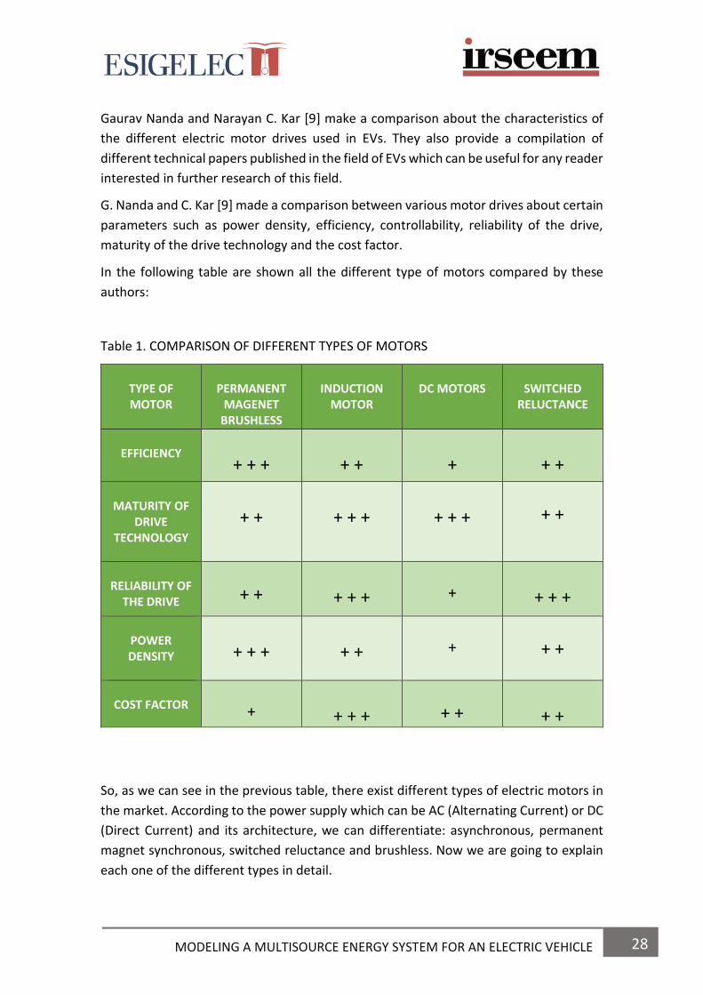
Gaurav Nanda and Narayan C. Kar [9] make a comparison about the characteristics of
the different electric motor drives used in EVs. They also provide a compilation of
different technical papers published in the field of EVs which can be useful for any reader
interested in further research of this field.
G. Nanda and C. Kar [9] made a comparison between various motor drives about certain
parameters such as power density, efficiency, controllability, reliability of the drive,
maturity of the drive technology and the cost factor.
In the following table are shown all the different type of motors compared by these
authors:
Table 1. COMPARISON OF DIFFERENT TYPES OF MOTORS
TYPE OF MOTOR
PERMANENT
MAGENET BRUSHLESS
INDUCTION
MOTOR
DC MOTORS
SWITCHED
RELUCTANCE
EFFICIENCY
+ + +
+ +
+
+ +
MATURITY OF
DRIVE TECHNOLOGY
+ +
+ + +
+ + +
+ +
RELIABILITY OF
THE DRIVE
+ +
+ + +
+
+ + +
POWER DENSITY
+ + +
+ +
+
+ +
COST FACTOR
+
+ + +
+ +
+ +
So, as we can see in the previous table, there exist different types of electric motors in
the market. According to the power supply which can be AC (Alternating Current) or DC
(Direct Current) and its architecture, we can differentiate: asynchronous, permanent
magnet synchronous, switched reluctance and brushless. Now we are going to explain
each one of the different types in detail.

29 MODELING A MULTISOURCE ENERGY SYSTEM FOR AN ELECTRIC VEHICLE
Asynchronous or Induction Motor (AC)
Its main feature is that the rotation of the rotor does not
correspond to the rotation speed of the magnetic field
generated by the stator. The rotor of this motor can be
either squirrel cage or winding type. In the stator are
located the inductor coils that are three-phase, lagged
each other at 120º.
Fig. 11 Asynchronous engine
Among the advantages are its high efficiency, low cost, reliability, low noise and
vibration and constant torque. In contrast, its disadvantages are its low power density,
low starting torque and the risk of overload. This is one of the most widely engines used
in the Electrical Vehicle industry. That’s why, Tesla Motors uses this type of motor.
Permanent magnet synchronous motor (AC)
This motor has a constant rotational speed. The rotation of
the rotor is the same as the speed of the magnetic field
generated by the stator. The permanent magnet
synchronous motor can be of two types; radial flow or axial
flow, depending on the position of the induction magnetic
field, which can be perpendicular or parallel to the axis of
rotation of the rotor. The most commonly used are the
radial flow. Fig. 12 Synchronous engine
The advantages of this type of motor are its high performance, simple speed control,
low noise, low vibration, size and weight. Although they have a high cost, they are the
most widespread among EVs and hybrids. The companies which use this type of motor
are Nissan, BMW, VW, Kia, Smart, Chevrolet, Opel, Toyota and Lexus.
Synchronous motor with switched reluctance. (AC)
In this type of engine, the current is switched
between the coils of each stator phase to create a
rotating magnetic field. The rotor, which is made of
a magnetic material with salient poles, is influenced
by the magnetic field, attracting themselves and
creating a torque that keeps the rotor moving at
synchronous speed.
Fig. 13 Switched reluctance engine

30 MODELING A MULTISOURCE ENERGY SYSTEM FOR AN ELECTRIC VEHICLE
These motors are characterized by having a great potential for being used in electrical
vehicles due to its simple construction. Moreover, among its advantages are its high
torque speed, robustness and low manufacturing cost. However, they present some
disadvantages such as having low power, complexity design, noise problems or not
achieving the level of efficiency or power density as compared with the permanent
magnet engines [8].
Renault and its Electric Powertrain department developed the 5A model, a synchronous
motor model more efficient than the permanent magnet model.
Brushless permanent magnet motor (DC)
These motors have permanent magnets located in the
rotor that operate by sequentially feeding each of the
stator phases. They may be "inrunner", higher rotation
speed and lower torque, or "outrunner", lower speed and
higher torque. Although they are mostly used in hybrid
vehicles, brushless motors offer some advantages for the
use in EV, such as low noise and friction, robustness and no
maintenance.
Fig. 14 Permanent magnet engine
At the moment they are inexperienced engines, which have a high price and low power.
Honda has assembled some of its electrical prototypes with this type of engine.
2.4.4 CONTROLLER
The controller of the EV is an electronic package that operates
between the batteries and the motor in order to control the
speed and the acceleration of the vehicle. They also check the
correct operation for efficiency and safety of the car and
regulate the energy which is received or recharged by the
motor.
Fig.15 Controller of an EV
For vehicles that has AC motors, the controller transforms the direct current provided
by the batteries into alternating current and also regulates the energy flow from the
battery. The controller can also reverse the motor rotation, and transform it into a
generator so the kinetic energy of motion would be used to recharge the battery during
braking. This action is known as regenerative braking, and during this process the brake
wear and the maintenance cost are diminished [10].

31 MODELING A MULTISOURCE ENERGY SYSTEM FOR AN ELECTRIC VEHICLE
2.4.5 ENERGY STORAGE SYSTEMS (ESS)
Energy storage systems are one of the most important elements in the electric vehicle
because without them, the car would not work. These systems are expected to have
high energy density, high power density, a good lifetime, be low cost, have a low
maintenance and to be environmentally friendly.
Over the years, scientists and engineers have developed a lot of different technologies
for achieve the best efficiency, quality and performance in these devices. Currently,
there exists a lot of different energy storage systems, but the dominating ones are
batteries, ultracapacitors and fuel-cells. So, in the next chapter it is going to be explained
the performance and the modelling of all these devices.
2.5 ADVANTAGES AND DISADVANTAGES OF USING EVs
From the environmental point of view, the use of electric cars offers a lot of advantages in comparison to combustion engine cars since these cars allow to reduce the level of CO2 emissions into the atmosphere. However, it is not always like this. They have also some disadvantages. In the following table we are going to see some advantages and disadvantages that the EV presents: Table 2. ADVANTAGES AND DISADVANTAGES OF USING EVs
ADVANTAGES DISADVANTAGES
Noise free
Low maintenance
Low drive cost
High torque and power
Effective traction control
Reduction of CO2 emissions
Efficiency around 90%
Use of regenerative braking
Application of V2G,V2B and VTH
Low charging time
High cost
Low autonomy
Batteries have a life-time

32 MODELING A MULTISOURCE ENERGY SYSTEM FOR AN ELECTRIC VEHICLE
2. STATE OF THE ART
Nowadays, the use of EV is being promoted due to the benefits it brings such as the
reduction of CO2 emissions, the absence of local pollution, the possibility of being
encouraged with renewable energies, the reduction of noise pollution, etc.
However, people are not aware of one of the great potentials that EVs have: its use as
an electrical storage system. Society talks about EV as a battery with wheels and they
do not realise that in a near future, where renewable energies will be the main source
of energy, having electricity storage is a great advantage to their rollout.
One of the biggest drawbacks of electrical energy is the impossibility to storing it in large
scale. The electrical energy that is being consumed at this moment is being produced at
the same time in another place, reaching our homes through the electrical grid. This is
where EVs could intervene for solving one of the humanity’s greatest challenge: to
dispose electricity storage in large-scale and to distribute it.
In a future where renewable energies will be present, EVs could be the key to the new
electrical system, due to having millions of electric cars connected to the electrical grid
means having millions of batteries connected into it.
This section explains the technologies that allow the use of EV as means of storing
electrical energy. Therefore, the V2G (Vehicle-to-Grid) and its variants V2H (Vehicle-to-
Home) and V2B (Vehicle-to-Building) are described below.
2.1 VEHICLE-TO-GRID TECHNOLOGY (V2G)
Vehicle-to-grid describes a system in which the driver of an electric or hybrid vehicle can sell the energy stored in its batteries to the electrical grid when the car is connected into it and is not being used for its main purpose: transportation. Alternatively, this technology allows energy to flow in the opposite direction, that means from the electrical grid towards the vehicle, when the vehicle’s batteries need to be recharged. According to several studies, most vehicles are parked 95%. If these vehicles are electric or hybrid, their batteries could be available as a distributed storage system, allowing the storage and future extraction of the energy, helping to the electrical system. Each vehicle requires these three elements:
A connection to the grid to allow the bidirectional flow of energy.
A logical connection for bidirectional communication with the network operator.
A series of controls and metering on-board the vehicle.
33 MODELING A MULTISOURCE ENERGY SYSTEM FOR AN ELECTRIC VEHICLE
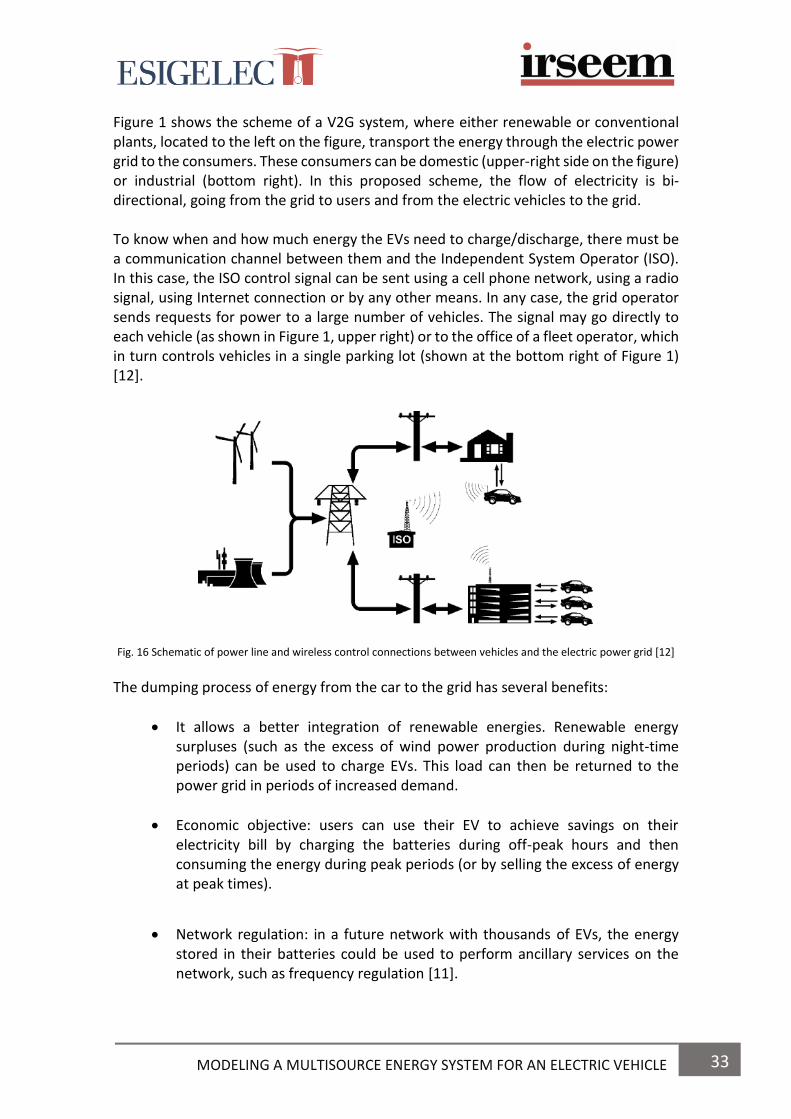
Figure 1 shows the scheme of a V2G system, where either renewable or conventional plants, located to the left on the figure, transport the energy through the electric power grid to the consumers. These consumers can be domestic (upper-right side on the figure) or industrial (bottom right). In this proposed scheme, the flow of electricity is bi-directional, going from the grid to users and from the electric vehicles to the grid. To know when and how much energy the EVs need to charge/discharge, there must be a communication channel between them and the Independent System Operator (ISO). In this case, the ISO control signal can be sent using a cell phone network, using a radio signal, using Internet connection or by any other means. In any case, the grid operator sends requests for power to a large number of vehicles. The signal may go directly to each vehicle (as shown in Figure 1, upper right) or to the office of a fleet operator, which in turn controls vehicles in a single parking lot (shown at the bottom right of Figure 1) [12].
Fig. 16 Schematic of power line and wireless control connections between vehicles and the electric power grid [12]
The dumping process of energy from the car to the grid has several benefits:
It allows a better integration of renewable energies. Renewable energy surpluses (such as the excess of wind power production during night-time periods) can be used to charge EVs. This load can then be returned to the power grid in periods of increased demand.
Economic objective: users can use their EV to achieve savings on their electricity bill by charging the batteries during off-peak hours and then consuming the energy during peak periods (or by selling the excess of energy at peak times).
Network regulation: in a future network with thousands of EVs, the energy stored in their batteries could be used to perform ancillary services on the network, such as frequency regulation [11].

34 MODELING A MULTISOURCE ENERGY SYSTEM FOR AN ELECTRIC VEHICLE
The biggest limitation of Vehicle-to-Grid technology is the need to coordinate the
operation of thousands of vehicles in real-time and therefore, there are only a few
experimental applications [13].
In 2013, Kempton connected 15 Mini-E cars to operate as a small power plant, which
was the birth of V2G technology.
There exist two other simpler variants from Vehicle-to-Grid for its small-scale use, called
Vehicle-to-Home (V2H) and Vehicle-to-Building (V2B). It is the same technology but
instead of being applied at the network level, it is applied at the household or building
level, respectively.
2.2 VEHICLE-TO-BUILDING TECHNOLOGY (V2B)
With this technology, a fleet of electric vehicles connected to the same building such as
offices, hospitals, universities, hotels, factories, etc. they can serve as a storage systems
and an emergency power supply system. The objectives can be varied:
Reducing the electricity bill, due to night-time recharging and the spill at rush hour.
Use of renewable energies for charge the vehicles with the renewable installation present in the building as for example, photovoltaic or mini wind.
Back-up. In the case of having a power outage, the fleet of vehicles could continue to supply power to the building instead of using the conventional generators.
2.3 VEHICLE-TO-HOME TECHNOLOGY (V2H)
Vehicle-to-Home technology is a variant of the Vehicle-to-Grid but specifically designed for homes. It uses the car as an electrical storage system, giving it the possibility to act as a power source for the house itself, either to reduce the electricity bill or as a back-up. One of its greatest potentials is its use as an emergency generator in those places most prone to natural disasters or with greater number of power outages due to a weak electrical grid. During these power outages, power from a vehicle’s battery can be used to run domestic appliances. In areas with frequent power outages, the battery can be used to buffer energy to avoid flickering, and it can be also used as an emergency survival kit.
35 MODELING A MULTISOURCE ENERGY SYSTEM FOR AN ELECTRIC VEHICLE
Moreover, Vehicle-to-home technology would improve the effectiveness of renewable
energy sources due to the excess generation can be stored and then used when
generation is low [14].
Vehicle-to-grid (V2G) is parallel, i.e. within a grid any car can be used to power any house by feeding its power back to the grid. In contrast, Vehicle-to-home is more limited; a single vehicle is used to supply a single house. The trade-off is simplicity versus flexibility; more vehicles working together offer flexible storage but will be more difficult to control.
A further discussion point is locality. V2G and V2H are a form of distributed generation; the electrical load is geographically close to the electrical source. Transmission is therefore minimal compared to centralised generation so costs of transmission infrastructure and transmission losses are reduced. V2H represents the simplest case with regards to infrastructure and transmission. A single house operating V2H will have simple infrastructure requirements and negligible transmission losses [14]. As a conclusion of all above mentioned, we can affirm that using these technologies (V2G, V2B and VTH) in EVs we will contribute to have a better future in which energy will be sustainable and as a result, the environment will be cleaner and greener since we will reduce the gas emissions that affect the global warming, an issue which is very important nowadays.

36 MODELING A MULTISOURCE ENERGY SYSTEM FOR AN ELECTRIC VEHICLE
CHAPTER 2 4. ESS FOR ELECTRIC VEHICLES
5. MODELLING OF ESS
37 MODELING A MULTISOURCE ENERGY SYSTEM FOR AN ELECTRIC VEHICLE
4. ENERGY STORAGE SYSTEMS FOR AN ELECTRICAL VEHICLE
4.1 BATTERIES
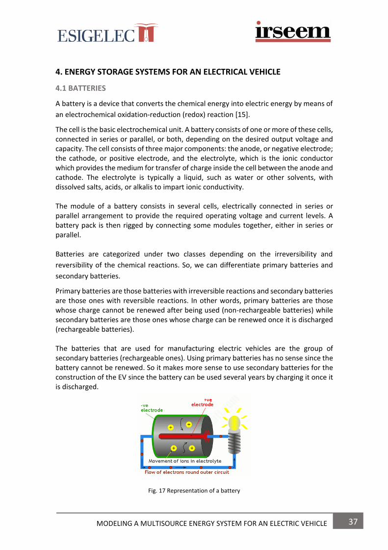
A battery is a device that converts the chemical energy into electric energy by means of
an electrochemical oxidation-reduction (redox) reaction [15].
The cell is the basic electrochemical unit. A battery consists of one or more of these cells, connected in series or parallel, or both, depending on the desired output voltage and capacity. The cell consists of three major components: the anode, or negative electrode; the cathode, or positive electrode, and the electrolyte, which is the ionic conductor which provides the medium for transfer of charge inside the cell between the anode and cathode. The electrolyte is typically a liquid, such as water or other solvents, with dissolved salts, acids, or alkalis to impart ionic conductivity. The module of a battery consists in several cells, electrically connected in series or parallel arrangement to provide the required operating voltage and current levels. A battery pack is then rigged by connecting some modules together, either in series or parallel. Batteries are categorized under two classes depending on the irreversibility and
reversibility of the chemical reactions. So, we can differentiate primary batteries and
secondary batteries.
Primary batteries are those batteries with irreversible reactions and secondary batteries are those ones with reversible reactions. In other words, primary batteries are those whose charge cannot be renewed after being used (non-rechargeable batteries) while secondary batteries are those ones whose charge can be renewed once it is discharged (rechargeable batteries). The batteries that are used for manufacturing electric vehicles are the group of secondary batteries (rechargeable ones). Using primary batteries has no sense since the battery cannot be renewed. So it makes more sense to use secondary batteries for the construction of the EV since the battery can be used several years by charging it once it is discharged.
Fig. 17 Representation of a battery

38 MODELING A MULTISOURCE ENERGY SYSTEM FOR AN ELECTRIC VEHICLE
The autonomy and the price of the car depend on the type and size of the battery in use.
That’s why we have to consider some parameters before choosing the type of battery
that would be used in the electric vehicle [16]. Some of them are:
o Energy density: Expressed in Wh/kg. It is the energy that the battery can supply per each kg. The greater it is the most autonomy the vehicle will have.
o Power: Expressed in W/kg. It is the ability to provide power (maximum amperage) in the discharge process. A more power better performances for the electric vehicle.
o Efficiency: It is the performance of the battery, the energy that it really
harnesses. Measured in %.
o Cost: It is the biggest influence on the total price of the vehicle.
o Life cycle: complete charge and discharge cycles supported by the battery before it is replaced. The more cycles the better, as it will last longer.
Nowadays, there exists a lot of different types of batteries which are used in EVs but we are going to mention the ones most well-known.
Lead-acid battery This is the most widely used type of battery and it is also the oldest of all. Their low cost makes them ideal for starting, lighting or electrical support functions, being used as accumulators in small vehicles. Its disadvantages are the excessive weight, the toxicity of the lead and its slow recharging.
Nickel-cadmium battery They are used in the automotive industry, but the high cost of acquisition of its elements is the first concern to have in mind. So is not the first option chosen by the manufacturers. They are more oriented towards aircraft, helicopters or military vehicles, due to their high performance at low temperatures. They have memory effect, so their capacity is reduced with each recharge.
Nickel-iron battery Developed by Thomas Edison and patented in 1903, these so-called "ferronickel" batteries are not currently mounted on vehicles because they have low power and efficiency. Its energy density is similar to that of lead-acid.
Nickel-metal hydride battery Similar to nickel-cadmium, they improve the capacity of these, and reduce the memory effect. Moreover, they are less aggressive to the environment. However, they have some disadvantages such as constant maintenance and deterioration when there exist high temperatures, high discharge currents or overloads. These batteries also generate too much heat and are recharged slowly.

39 MODELING A MULTISOURCE ENERGY SYSTEM FOR AN ELECTRIC VEHICLE
Lithium-ion battery (LiCoO2) Batteries of recent creation, after the 90’s, formed by a lithium salt electrolyte and lithium, cobalt and oxide electrodes. The use of new materials such as lithium has allowed to achieve high specific energies, high efficiency, elimination of the memory effect, absence of maintenance and ease of recycling lithium-ion waste. They have twice the energy density of nickel-cadmium batteries with a size of about a third smaller. But they also have disadvantages, the main one is their high production cost, although this is gradually being reduced, they are fragile, they can explode due to overheating and they must be stored very carefully, both because they need a cold environment and because they must be partially charged. Even so, lithium-ion batteries are still the best choice for mounting on a EV today.
LiFePO4 battery This type of lithium-ion battery is similar to the previous one, with the difference that it does not use cobalt, so it has greater stability and safety of use. Other advantages are a longer life cycle and higher power. As disadvantages to highlight its lower energy density and high cost.
Battery Lithium polymer Another variation of the lithium-ion that has some improvements such as higher energy density and higher power. They are light, efficient and have no memory effect. On the other hand, their high cost and low life cycle make these batteries, with a "soft" appearance due to their lithium and polymer components, an option that is not very widespread at present.
Battery ZEBRA These batteries, also called molten salt batteries, work at 250ºC and have crushed
sodium chloroaluminate as electrolyte. It is a complex battery, with a higher chemical
content, but which achieves interesting energy and power characteristics. In disuse, the
electrolyte solidifies, so it needs a melting time that can be up to two days to reach the
optimal temperature and fully offer its charge. They have the best life cycle of all
batteries, but they require a lot of space and their power is low.
Aluminum-air battery Considered "fuel cells" because of the need to replace spent metal electrodes with new ones. With a storage capacity up to ten times greater than that of the lithium-ion type and an energy density beyond the reach of the rest, this type of battery has not been well accepted commercially due to its problems of recharging and reliability. They are in experimental phase.
Zinc-Air Battery They are more advanced than Aluminum-Air and they need to obtain oxygen from the atmosphere to generate a current. It has a high energy potential, reliability and they are able to store three times the energy of lithium-ion batteries in the same volume and half the cost. According to some experts, zinc is positioned as the electric fuel of the future.
40 MODELING A MULTISOURCE ENERGY SYSTEM FOR AN ELECTRIC VEHICLE
Despite there are a lot of different types of batteries which are used for the manufacturing of EVs, we have to know that there are three types that are the most suitable for the use of EVs due to their specifications and efficiency. Those types are lead-acid batteries, nickel metal hydride batteries (NiMH) and lithium-ion batteries (Li-ion). We are now going to explain each one of them to see their characteristics. 4.1.1 LEAD ACID BATTERIES
Lead-acid batteries were invented in 1856 and they are the oldest form of rechargeable battery still in use. They have been used in all types of cars, either internal combustion engine and electric cars, since the 19th century. These batteries are a kind of wet cell battery and they usually contain a mild solution of sulphuric acid in an open container. The name of the battery comes from the combination of lead electrodes and acid which is used to generate electricity. One of the major advantages of these batteries is that they are well understood after being used for so many years and they are also cheap to produce. Nevertheless, they have some disadvantages such as the production of dangerous gases, low specific energy, excessive weight, slow recharging and the risk of explosion if the battery is overcharged [17]. 4.1.2 LITHIUM-ION BATTERIES
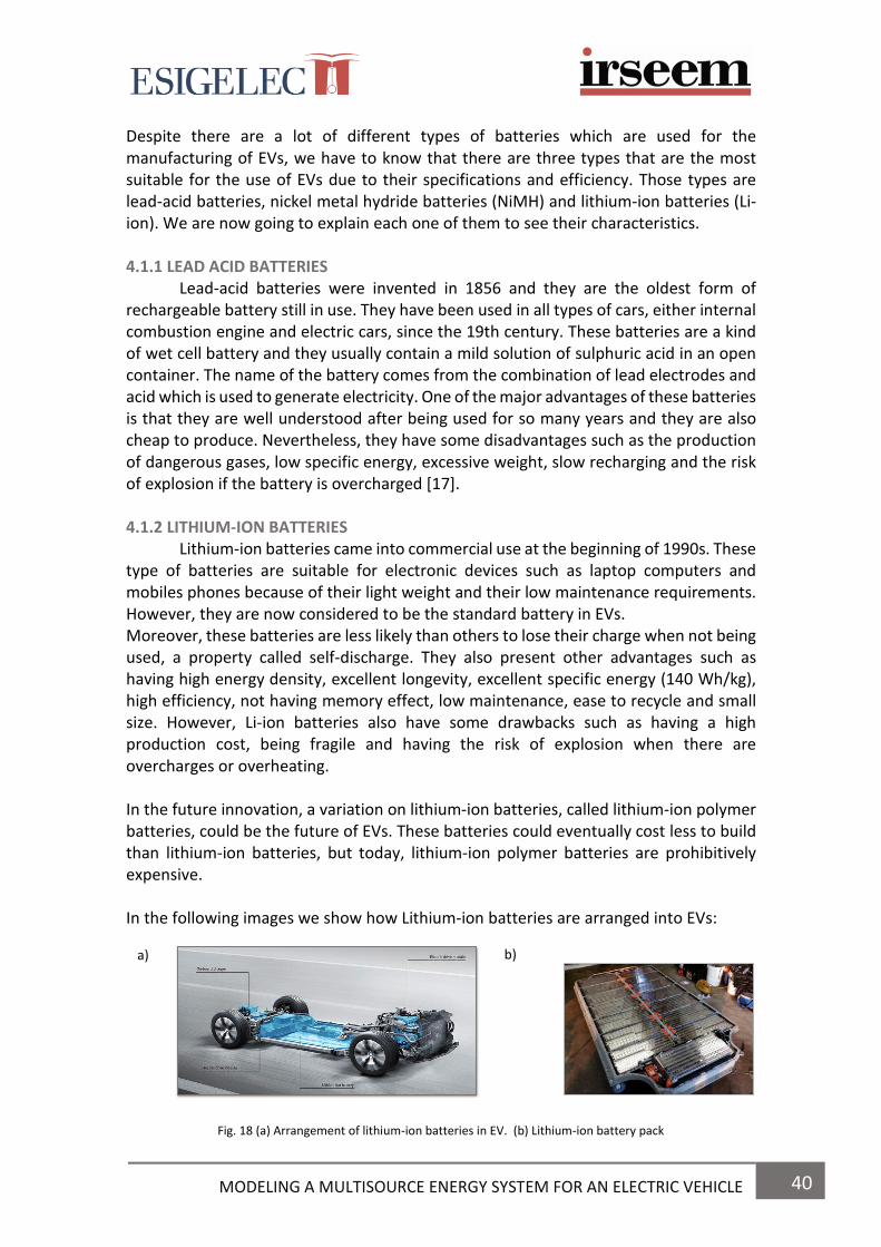
Lithium-ion batteries came into commercial use at the beginning of 1990s. These type of batteries are suitable for electronic devices such as laptop computers and mobiles phones because of their light weight and their low maintenance requirements. However, they are now considered to be the standard battery in EVs. Moreover, these batteries are less likely than others to lose their charge when not being used, a property called self-discharge. They also present other advantages such as having high energy density, excellent longevity, excellent specific energy (140 Wh/kg), high efficiency, not having memory effect, low maintenance, ease to recycle and small size. However, Li-ion batteries also have some drawbacks such as having a high production cost, being fragile and having the risk of explosion when there are overcharges or overheating. In the future innovation, a variation on lithium-ion batteries, called lithium-ion polymer batteries, could be the future of EVs. These batteries could eventually cost less to build than lithium-ion batteries, but today, lithium-ion polymer batteries are prohibitively expensive. In the following images we show how Lithium-ion batteries are arranged into EVs:
Fig. 18 (a) Arrangement of lithium-ion batteries in EV. (b) Lithium-ion battery pack
b) a)

41 MODELING A MULTISOURCE ENERGY SYSTEM FOR AN ELECTRIC VEHICLE
As we can see in Fig. 18 (b), the battery pack is formed by connecting some modules
together and it is situated in the base of the chassis (see Fig. 18 (a)). This arrangement
of the battery pack makes a better distribution of the weight of the car and also provides
more space for the other elements of the EV while manufacturing.
4.1.3 NICKEL METAL HYDRIDE BATTERIES
Nickel metal hydride batteries came into commercial use at the end of 1980. The principal advantages are having high energy density, reduction of memory effect, ease to recycle due to they don’t contain toxic metals and as a result, they are environmentally friendly. However, they present some disadvantages such as having poor specific energy, slow recharging and easy deterioration at high temperatures or overloads. These type of batteries are being replaced by lithium-ion batteries because they have better specifications for the performance of EV.
4.1.4 BATTERY MANAGEMENT SYSTEM FOR EVs
Despite all the good advantages that batteries present, they can present unstable
behaviour that can potentially lead to thermal runaway. This is the main reason why
batteries need a battery management system (BMS) as saw in [18,19,20].
A BMS measures current, battery pack voltage, module voltages, and temperature. The
system analyses these data and controls sub-systems to optimize the status of the
traction batteries. The functions of a BMS include the following: data acquisition,
charging optimization, calculation and display of SOC, thermal management, safety
management, energy management, auxiliary battery management, and diagnostics
[18]. The BMS also protect the battery from under-voltage/overvoltage, short-circuit
and thermal runway [19].
The structure of a BMS for an EV battery is shown schematically in Fig. 20
Fig. 19 Schematic structure of BMS [3]

42 MODELING A MULTISOURCE ENERGY SYSTEM FOR AN ELECTRIC VEHICLE
Y. Jung and B. Haeng explains all the functions of a BMS installed in a DEV5-5 electric
vehicle with a Panasonic nickel-metal hydride (Ni-MH) battery [18].
As a conclusion, we can affirm that the use of a BMS in EVs provides an improvement in
the energy efficiency and the cycle-life of the battery. Moreover, having this system
enhances the safety and the reliability of EVs.
4.1.5 TABLE COMPARATIVE OF BATTERIES FOR EVs In the following table we can see the advantages and disadvantages of the three types of batteries explained before, and see which one is better for the best performance of the EV. TABLE 3. TABLE COMPARATIVE OF BATTERIES FOR EVs
*Memory effect in batteries: Phenomena which reduces the capacity of the battery with incomplete
charges.
TYP
E O
F
BA
TTER
Y
LEAD-ACID
LITHIUM-ION
NICKEL METAL
HYDRIDE
AD
VA
NTA
GES
Low production cost The oldest battery still in use (more than 50 years) The battery most used
High energy density (400 Wh/L) High specific energy (150 Wh/Kg) High efficiency Smaller size Long cycle life (greater than 1000 cycles) Low self-discharge rate (2% to 8% per month) Low maintenance Low memory effect* Recyclables Good performance at high temperatures
Higher energy density (twice than lead-acid battery) Environmentally friendly Low memory effect High specific energy Long service life (3-5 years) No toxic metals Easy to recycle Safe to operate at high voltage Durable and safe Wide allowable temperature ranges for charging (0-50ºC)

43 MODELING A MULTISOURCE ENERGY SYSTEM FOR AN ELECTRIC VEHICLE
TABLE 3. TABLE COMPARATIVE OF BATTERIES FOR EVs
As we can see in the tables, among all the batteries exposed, the lithium-ion represent
nowadays the best choice for the manufacture of the Electric vehicles due to the
advantages they have.
TYP
E O
F B
ATT
ERY
LEAD-ACID
LITHIUM-ION
NICKEL METAL HYDRIDE
DIS
AD
VA
NTA
GES
Production of dangerous gases Risk of explosion if the battery is overcharged Excessive weight Slow recharging Toxicity of lead Limited life cycle if operates at a deep rate of SOC
High production cost Degradation at high temperatures Fragile They can explode due to overheating They must be stored carefully Increasing of temperature while charging and discharging
Less tolerant to overcharge Less efficiency than lead-acid in charging and discharging Slow recharging Expensive cost Generation of heat Constant maintenance Deterioration in high temperatures, high discharge currents or overloads.
44 MODELING A MULTISOURCE ENERGY SYSTEM FOR AN ELECTRIC VEHICLE
4.2 SUPERCAPACITORS
Supercapacitors, also called ultracapacitors or electrochemical double-layer capacitors, are electrochemical storage devices which are characterized due to their ability to charge and discharge very quickly, their high power density (10 kW kg), the high number of charging cycles, their high specific power, their long cycle life, and for having a good response in taking electricity from regenerative braking. However, they have some drawbacks such as having a short shelf life, ineffectiveness at high charges, low specific energy, high self-discharge and toxicity of ruthenium oxide due to its use. These devices are a suitable choice in fast energy storage applications, where highly dynamic charging and discharging with high current rates are required, such as the recharge of an electric car. However, they do not have a good shelf life, so there are some applications that use batteries with a high power usage or high-energy density instead of using supercapacitors because these have a good shelf life. Another inconvenient about supercapacitors is their price, because these devices are very expensive in comparison to lead-acid or lithium-ion batteries, and this is because of the materials they use. Generally, according to Huang and Qi in [21], there are two types of supercapacitors, in terms of their operation mechanisms: the EDLC (Electrical Double Layer Capacitor) and the pseudocapacitor. On one hand, the EDLC, stores energy via an electrostatic process: the charges are accumulated at the electrode/electrolyte interface through polarization. Hence, it is important to use electrode materials with good conductivity and large specific surface areas in EDLCs, such as the activated carbon, CNTs, carbon nanofibers, and the emerging graphene-based 2D sheets. The graphene-based materials are advantageous in terms of the chemically active surface with large specific area, good conductivity, low cost, and mass production with solution-based processability [21]. On the other hand, the other type of supercapacitor is called pseudocapacitor. This is based on the redox reactions of the chemical species present in the electrode. Commonly used electrode materials are metal oxides (RuO2, NiO and MnO2) and conducting polymers (Polyaniline, PANi and Polypryrole, PPy). This type of electrode affords higher specific capacitance per unit surface area compared to the porous carbon based EDL electrode. However, the relatively high cost and low conductivity of metal oxides or conducting polymers have limited their applications [21]. There exists another type of supercapacitor called ‘’Hybrid Supercapacitor’’. This supercapacitor is a combination of graphene derivatives and metal oxides or conducting polymers, as for example the combination of the EDLC with pseudo-capacitor. Despite the advantages that supercapacitors present, they cannot be yet considered as
an alternative to batteries because their benefits satisfy different needs for energy
storage. For example, for a process which requires fast charge and discharge for a

45 MODELING A MULTISOURCE ENERGY SYSTEM FOR AN ELECTRIC VEHICLE
limited range of capacities and time, supercapacitors are the best choice as energy
storage system, otherwise there are different types of batteries with a reliable shelf life
for high power usage or high energy density needs which are more adequate to use as
energy storage system instead of using supercapacitors.
Moreover, supercapacitors present some differences in comparison to the conventional capacitors. We can find some of them on the following table: TABLE 4. DIFFERENCES BETWEEN CAPACITOR AND SUPERCAPACITOR
Furthermore, Burke and Zhao [22] studied the applications of supercapacitors in electric
drive vehicles in place of or in combination with batteries. In the study, they found that
the vehicles using supercapacitors had even better performance than those using
batteries and they also were more efficient. They make a comparison between the price
of lithium batteries and supercapacitors.
They also made some simulations using carbon/carbon and hybrid supercapacitors, and
the results for fuel cell vehicles indicated that the use of supercapacitors would permit
the use of energy storage units storing less energy and having higher efficiency than
using lithium batteries [22].
Other authors such as Zhang [23] and Zhi [24] studied the characteristics of the different
types of capacitors such as EDLC, pseudocapacitors and hybrid capacitors, as well as the
materials used for this kind of devices.
CAPACITOR
SUPERCAPACITOR
Definition
In capacitors, energy is stored in their electrical field
A supercapacitor tends to differ from an ordinary capacitor due to its very high capacitance.
Energy Density
Comparatively low
Comparatively high
Cost Comparatively cheap
Comparatively expensive
Dielectric materials
Dielectric materials like ceramic, polymer films or aluminium oxide are used for the separation of the electrodes.
Activated carbon is used as a physical barrier between the electrodes so that when an electrical charge is applied to the material a double electric field is generated. This electric field acts like a dielectric

46 MODELING A MULTISOURCE ENERGY SYSTEM FOR AN ELECTRIC VEHICLE
In the following table we show the different types of supercapacitors:
TABLE 5. DIFFERENT TYPES OF SUPERCAPACITORS
TYP
E O
F SU
PER
CA
PA
CIT
OR
EDLC
PSEUDOCAPACITOR
HYBRID CAPACITOR
ELEC
TRO
DE
MA
TER
IAL
Carbon Redox metal oxide or redox polymer
Anode: pseudocapacitance Cathode: carbon
A
DV
AN
TAG
ES
Good cycling stability Good rate capability
High specific capacitance High energy density High power density
Higher energy density than for EDLC High power density Good cyclability Moderate cost
D
ISA
DV
AN
TAG
ES
Low energy density Low specific capacitance
Low rate capability
Requires electrode material capacity match
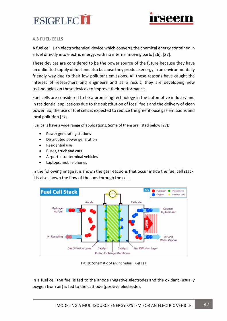
47 MODELING A MULTISOURCE ENERGY SYSTEM FOR AN ELECTRIC VEHICLE
4.3 FUEL-CELLS
A fuel cell is an electrochemical device which converts the chemical energy contained in
a fuel directly into electric energy, with no internal moving parts [26], [27].
These devices are considered to be the power source of the future because they have
an unlimited supply of fuel and also because they produce energy in an environmentally
friendly way due to their low pollutant emissions. All these reasons have caught the
interest of researchers and engineers and as a result, they are developing new
technologies on these devices to improve their performance.
Fuel cells are considered to be a promising technology in the automotive industry and
in residential applications due to the substitution of fossil fuels and the delivery of clean
power. So, the use of fuel cells is expected to reduce the greenhouse gas emissions and
local pollution [27].
Fuel cells have a wide range of applications. Some of them are listed below [27]:
Power generating stations
Distributed power generation
Residential use
Buses, truck and cars
Airport intra-terminal vehicles
Laptops, mobile phones
In the following image it is shown the gas reactions that occur inside the fuel cell stack.
It is also shown the flow of the ions through the cell.
Fig. 20 Schematic of an individual Fuel cell
In a fuel cell the fuel is fed to the anode (negative electrode) and the oxidant (usually
oxygen from air) is fed to the cathode (positive electrode).

48 MODELING A MULTISOURCE ENERGY SYSTEM FOR AN ELECTRIC VEHICLE
An electric current is produced through the electrolyte by means of electrochemical
reactions that occur inside the cell.
Although fuel cells are similar to batteries, they have some differences; batteries have
all the energy stored within them, so they only need to be recharged once the energy is
discharged. In contrast, fuel-cells are energy conversion devices in which fuel and
oxidant are supplied continuously, so they can power energy for as long as fuel is
supplied.
There exist a lot of different types of fuel cells and they are classified according to the
choice of the electrolyte and fuel they are using.
Some authors such as J.V. Mierlo [28] and [25] have studied the different types of Fuel-
cells that exists.
In the following table we can see some differences between Alkaline, Proton Exchange
Membrane, solid oxides, direct methanol, melted carbonate, and phosphoric acid Fuel-
cells.
TABLE 6. DIFFERENT TYPES OF FUEL CELLS
AFC
PEM
SOFC
DMFC
MCFC
PAFC
Electrolyte
used
Alkaline
Polymers membrane
Solid oxide Polymers membrane
Melted carbonate
Phosphoric acid
Fuel
H2
H2
H2,CH4,CO2
Metanol
H2,CH4,CO2
H2
Operating
temperatura
(ºC)
70-100
70-90
800-1000
70-90
600-650
200-220
Current
density
High
High
Moderate
Moderate
High
Moderate
Efficiency
70%
60%
60%
40%
60%
40%
Cost
Good
Good
Fair-good
Poor-fair
Fair-good
Fair
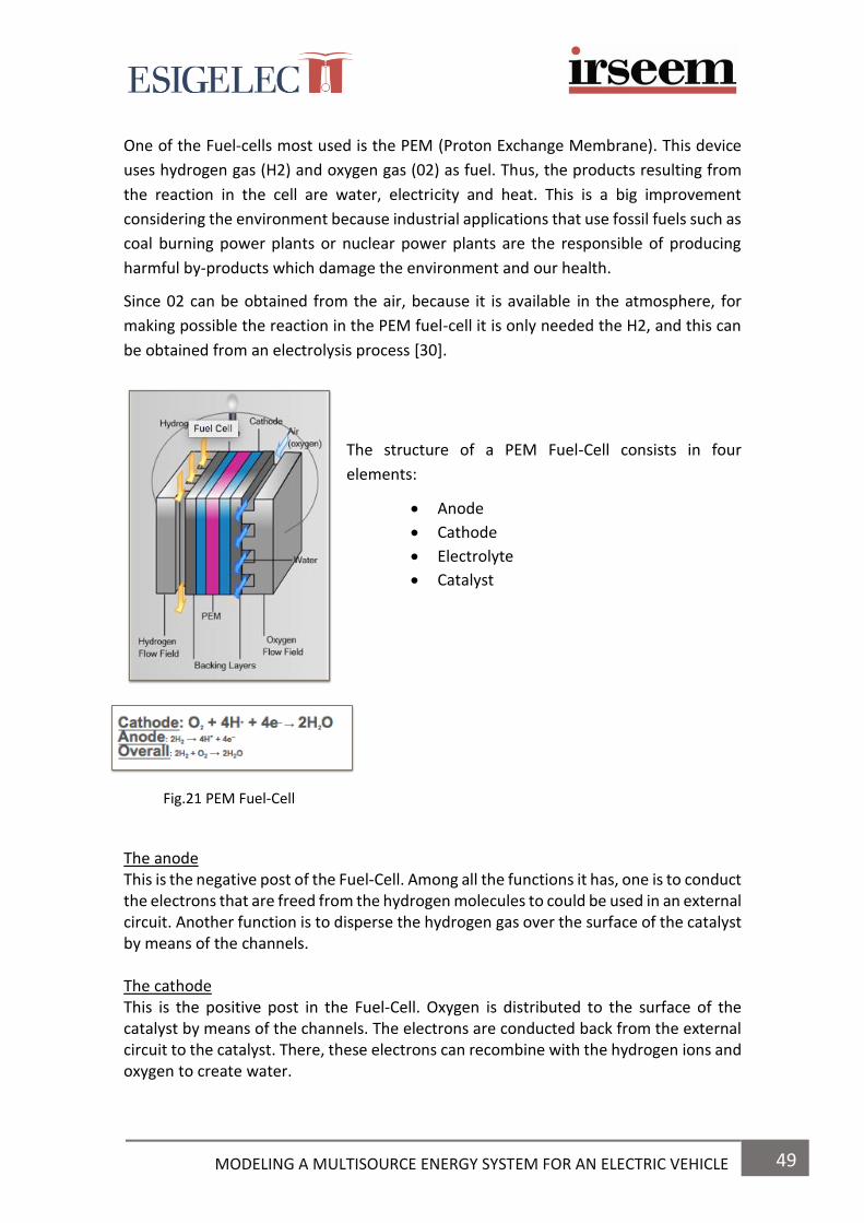
49 MODELING A MULTISOURCE ENERGY SYSTEM FOR AN ELECTRIC VEHICLE
One of the Fuel-cells most used is the PEM (Proton Exchange Membrane). This device
uses hydrogen gas (H2) and oxygen gas (02) as fuel. Thus, the products resulting from
the reaction in the cell are water, electricity and heat. This is a big improvement
considering the environment because industrial applications that use fossil fuels such as
coal burning power plants or nuclear power plants are the responsible of producing
harmful by-products which damage the environment and our health.
Since 02 can be obtained from the air, because it is available in the atmosphere, for
making possible the reaction in the PEM fuel-cell it is only needed the H2, and this can
be obtained from an electrolysis process [30].
The structure of a PEM Fuel-Cell consists in four
elements:
Anode
Cathode
Electrolyte
Catalyst
Fig.21 PEM Fuel-Cell
The anode
This is the negative post of the Fuel-Cell. Among all the functions it has, one is to conduct the electrons that are freed from the hydrogen molecules to could be used in an external circuit. Another function is to disperse the hydrogen gas over the surface of the catalyst by means of the channels. The cathode This is the positive post in the Fuel-Cell. Oxygen is distributed to the surface of the catalyst by means of the channels. The electrons are conducted back from the external circuit to the catalyst. There, these electrons can recombine with the hydrogen ions and oxygen to create water.
50 MODELING A MULTISOURCE ENERGY SYSTEM FOR AN ELECTRIC VEHICLE
The electrolyte This element is the proton exchange membrane. This material only conducts positively charged ions. Moreover, the membrane blocks electrons. For a PEMFC, in order to function and remain stable, the membrane must be hydrated. The catalyst The catalyst is a special material which facilitates the reaction between oxygen and hydrogen. Normally, it is made of platinum nanoparticles very thinly coated onto carbon paper or cloth. This material is porous and rough so the surface area of platinum can be exposed to the hydrogen or oxygen. The platinum-coated side of the catalyst faces the PEM.
APPLICATIONS OF PEM FUEL CELLS Since Fuel-Cells have a very high efficiency, they are considered a suitable technology for being used in many applications such as transport or as a backup power to provide electricity during a failure in the electrical grid [30]. One of the first applications of Fuel-Cells in the sector of transport was in space vehicles, based on the reactions between hydrogen and oxygen which results in water and that could be used by astronauts to drink or to cool the ship’s systems In automotive applications, PEM Fuel-Cells are the most suitable choice because their
working conditions at low temperature allow the system to start up quicker than those
technologies that use high temperatures fuel cells. In addition, their high power density
and the solid state of their electrolyte (since it doesn’t have leakage and corrosion) make
them appropriate for transport applications [29].
MATHEMATICAL MODELLING OF FUEL CELLS
Fuel cells developers use the fuel cell modelling because it makes the work easier since
they do not have to build again the system in case of failure. Another advantage is that
with simulations and modelling systems developers can make the test at any time they
want and also as much as they want. So, by this way, they can make more improvements
by means of simulations. This way of work is cheaper, more efficient and also more
accurate.
The model has to be robust and exact, and it also has to be fast when providing solutions
to fuel cell problems. A good model is supposed to predict the performance of a fuel cell
under a wide range of fuel cell operating conditions. The most important parameters to
include in a fuel cell model are: the cell, fuel and oxidant temperatures, fuel or oxidant
pressures, weight fraction of each reactant and cell potential [26].
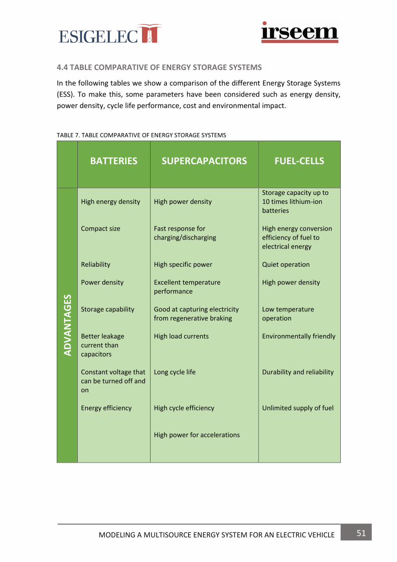
51 MODELING A MULTISOURCE ENERGY SYSTEM FOR AN ELECTRIC VEHICLE
4.4 TABLE COMPARATIVE OF ENERGY STORAGE SYSTEMS
In the following tables we show a comparison of the different Energy Storage Systems
(ESS). To make this, some parameters have been considered such as energy density,
power density, cycle life performance, cost and environmental impact.
TABLE 7. TABLE COMPARATIVE OF ENERGY STORAGE SYSTEMS
BATTERIES
SUPERCAPACITORS
FUEL-CELLS
AD
VA
NTA
GES
High energy density Compact size Reliability Power density Storage capability Better leakage current than capacitors Constant voltage that can be turned off and on Energy efficiency
High power density Fast response for charging/discharging High specific power Excellent temperature performance Good at capturing electricity from regenerative braking High load currents Long cycle life High cycle efficiency High power for accelerations
Storage capacity up to 10 times lithium-ion batteries High energy conversion efficiency of fuel to electrical energy Quiet operation High power density Low temperature operation Environmentally friendly Durability and reliability Unlimited supply of fuel

52 MODELING A MULTISOURCE ENERGY SYSTEM FOR AN ELECTRIC VEHICLE
TABLE 7. TABLE COMPARATIVE OF ENERGY STORAGE SYSTEMS
BATTERIES
SUPERCAPACITORS
FUEL-CELLS
DIS
AD
VA
NTA
GES
Limited cycle life Voltage and current limitations Long charging times Sensitive to temperatures
Ineffective at high charges Short shelf life Toxic electrode material (ruthenium) Low energy density Low specific energy Linear discharge voltage High self-discharge They can be deep discharged
Problems of recharging and reliability Very high cost Low volume production Large electrical power losses in the electrolyte
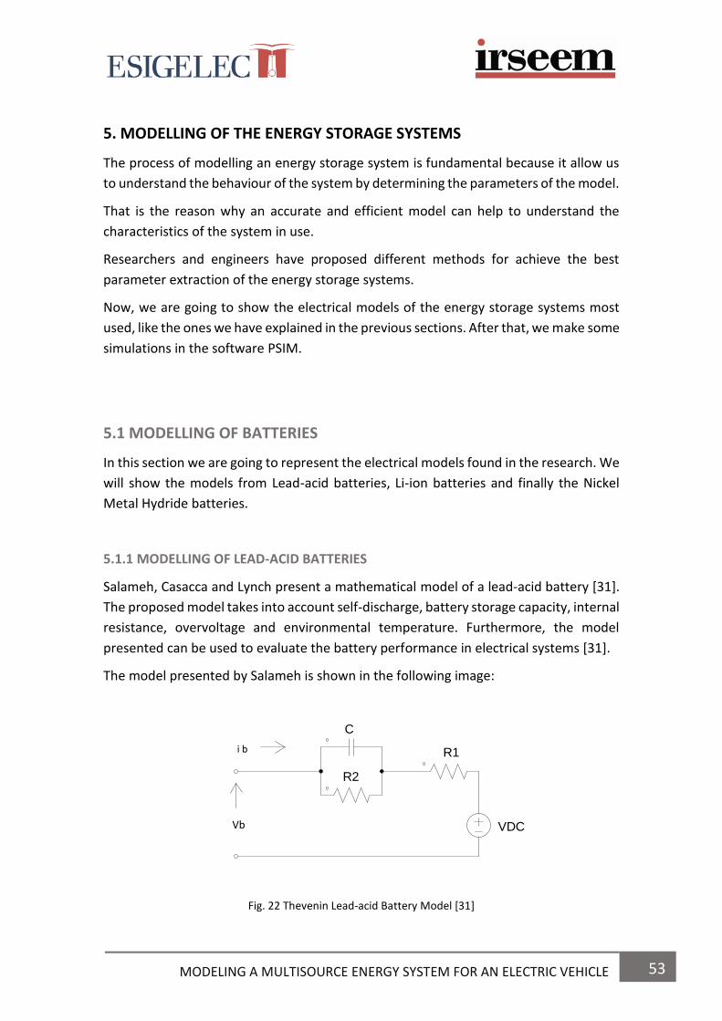
53 MODELING A MULTISOURCE ENERGY SYSTEM FOR AN ELECTRIC VEHICLE
5. MODELLING OF THE ENERGY STORAGE SYSTEMS
The process of modelling an energy storage system is fundamental because it allow us
to understand the behaviour of the system by determining the parameters of the model.
That is the reason why an accurate and efficient model can help to understand the
characteristics of the system in use.
Researchers and engineers have proposed different methods for achieve the best
parameter extraction of the energy storage systems.
Now, we are going to show the electrical models of the energy storage systems most
used, like the ones we have explained in the previous sections. After that, we make some
simulations in the software PSIM.
5.1 MODELLING OF BATTERIES
In this section we are going to represent the electrical models found in the research. We
will show the models from Lead-acid batteries, Li-ion batteries and finally the Nickel
Metal Hydride batteries.
5.1.1 MODELLING OF LEAD-ACID BATTERIES
Salameh, Casacca and Lynch present a mathematical model of a lead-acid battery [31].
The proposed model takes into account self-discharge, battery storage capacity, internal
resistance, overvoltage and environmental temperature. Furthermore, the model
presented can be used to evaluate the battery performance in electrical systems [31].
The model presented by Salameh is shown in the following image:
Fig. 22 Thevenin Lead-acid Battery Model [31]
C
R1
R2
VDCVb
i b

54 MODELING A MULTISOURCE ENERGY SYSTEM FOR AN ELECTRIC VEHICLE
This model is a simple way of demonstrating the behaviour of battery voltage (Vb). It
contains the electrical values of no-load voltage (Voc), internal resistance (R1) and
overvoltage (parallel combination of C and R2). This model is not accurate because these
values are not constants [31].
Another model analysis is presented in [31] by Salameh as follows:
Fig. 23 Lead-acid Battery equivalent circuit [31]
C1 = Overvoltage capacitance Rp= self-discharge resistance
Cb= battery capacity Rsc= internal resistance for charge
ib= current source Rsd= internal resistance for discharge
ip = parallel current Vb = battery voltage
R1c= charge overvoltage resistance Voc= open circuit voltage
R1d= discharge overvoltages resistance
The proposed mathematical battery model shown in Fig. 24 was arrived at after a series
of experimental tests. Once the behaviour of the components was understood a
computer simulation of the test cycle was designed to simulate the operation of the
battery [31].
Ceraolo talks about the problem of simulating electrochemical batteries by making
equivalent electric circuits [32]. He also explains the battery behaviour over short or
long-term intervals during its charge/discharge process.
Moreover, a simulation of a Lead-acid battery is made in the section III [32].
R1c
R1d
C1
Rsc
Rsd
CbRpVb
ib
Voc
ip
55 MODELING A MULTISOURCE ENERGY SYSTEM FOR AN ELECTRIC VEHICLE
Finally, a comparison is made between the behaviour of the models proposed and the
results obtained from a large number of tests using different types of lead-acid batteries.
Rynkiewicz explains the discharge and charge modelling in Lead-Acid batteries. He also
explains that discharge and charge reversibly oxidize/reduce the active materials of the
electrodes in the batteries [33].
He presents the measured terminal voltage for a 6 cell, sealed lead-acid battery during
charge and discharge at different constant currents.
Mauracher and Karden [34] propose a dynamic modelling of a lead-acid acid battery to
determine the parameters from its electrical model by means of the impedance
spectroscopy.
A battery model is set up for provide the terminal voltage. The model structure is based
on Randles’ equivalent circuit shown in [34].
After all simulations are done, we can see that the experiment referred to in Fig. 20 in
[34] is the most realistic test of the battery model. That is due to the good results.
Moreover, these results make the battery model very convincing, because that
demonstrates the stability of the battery model against ageing, state-of-charge and
temperature.
The model performance is also satisfactory even during intermittent charging caused by
regenerative braking.
Zhan, Kromlidis, Ramachandaramurthy, Barnes, Jenkins and Ruddell [35] present two
simple electrical models of lead-acid batteries to investigate the performance of the
dynamic voltage restorer (DVR) system. The first model is a short-term discharge model
and the second one is a long-term integrated model.
On one hand, the short-term discharge model, is based on the Thevenin battery model
and it was made to give a simple model when the DVR supply high-rate discharge
currents during voltage drops.
On the other, a long-term discharge/charge electrical model was developed to describe
the electrical response during charge and discharge long-time periods. This model can
predict the terminal voltage, the state of charge, the battery capacity and the gassing
current.
Some issues as the harmonics and microcycles during the process of charging and
discharging are commented for demonstrate the negative impact on loss of capacity and
lifetime of lead-acid batteries.

56 MODELING A MULTISOURCE ENERGY SYSTEM FOR AN ELECTRIC VEHICLE
In the following image, we show the short-term discharge electrical model presented in
[35]:
Short-term discharge electrical model
Fig. 24 Equivalent circuit of the short-term Thevenin-discharge lead-acid battery model [35]
Where:
Rp: ohmic polarisation resistance
Ro: discharge overvoltage resistance
C: overvoltage capacitance
Ep: open circuit electrochemical potential. It represents the equilibrium e.f.m of the
battery under no load conditions.
This electrical model can describe the external output characteristic of the lead-acid
battery with a high precision level.
In the following section [35], the parameter identification of this electrical model is done
from simulation tests.
In the following image, we show the long-term integrated electrical model also
presented in [35]:
Long-term electrical model
Fig. 25 Equivalent circuit of the long-term integrated lead-acid battery model [35]
Rp
Ro
C
Ep
Vbat
ibat
Rohm
Rt Rd
C
Ep
Es
Gsd
is
ibat
Vbatid
ip

57 MODELING A MULTISOURCE ENERGY SYSTEM FOR AN ELECTRIC VEHICLE
This model is based on Giglioli’s fourth-order model.
This model combines the diffusion time coefficient and active-polarisation time
coefficient into an integrated electrical time coefficient [35].
The parameters of the electrical model are:
Rohm: ohmic polarisation resistance
Rt: charge-transfer resistance
Rd: diffusion resistance
C: integrated capacitance
Ep: open-circuit electrochemical potential
Gsd: self-discharge conductance
Es: gassing voltage
In the following section [35], the parameter identification of this electrical model is done
by experimental data from simulation tests.
Appelbaum and Weiss [36] propose an electric circuit model of lead-acid battery. The
model proposed consists on a RC network with three time constants in addition to the
voltage source and the self-discharge resistance.
For modeling lead-acid batteriess we can make use of a set of non-linear differential
equations which describe the electrochemical processes.
Apart from chemical reactions, other processes take place inside the battery are
overvoltages.
The aim of this article is to present an electrical equivalent circuit model of a lead-acid
battery to represent its static and dynamic operation.
The simple static model contains a voltage source in series with a small resistance. For
the dynamic representation, a resistor-capacitor combination is added to the static
model, as shown in the following figure:
Fig. 26 Simple electrical lead-acid battery model [36]
C
R1
R2
VDCVb
i b

58 MODELING A MULTISOURCE ENERGY SYSTEM FOR AN ELECTRIC VEHICLE
In the figure, Vdc is the open circuit voltage, ib is the terminal current and vb is the
terminal voltage.
We can compare this model with the one studied previously in [31] by Salameh, Casacca
and Lynch, and as we can see, the model used in [36] is exactly the same which was used
in [31].
A piecewise-linear model with lumped elements is proposed for the battery cell as
shown in the following figure:
Fig. 27 Proposed linear electrical lead-acid battery model [36]
Where:
Rsd: self-discharge resistance
Cel: electrochemical capacitance of the battery cell
Vdco: open circuit voltage of a fully discharge battery cell
R1, R2, R3: resistances
C1, C2, C3: capacitances
Voc: open circuit battery cell voltage
Km: battery cell overvoltage
Vbat, ib: battery cell terminal voltage and terminal current
Ip: self-discharge current
The voltage Eo and the capacitance Cb represent the basic electrochemical process of
charge storage. The three resistances and capacitances represent the dynamic response
of the three dominant battery overvoltages, and Rp describes the self-discharge effect.
R1 C1
R2 R3
C2 C3Km(t)
CelRsd
VDCo
A
BB
C
Vbat (t)
ib (t)
ip
Voc (t)

59 MODELING A MULTISOURCE ENERGY SYSTEM FOR AN ELECTRIC VEHICLE
This model proposed of a lead-acid battery represents the different chemical processes
that occur inside it.
The battery equation of the electrical model is:
𝑉𝑏(𝑡) = 𝑉𝐴𝐵 + 𝑉𝐵𝐶 = 𝑉𝑂𝐶(𝑡) + ᶯ𝑚(𝑡)
This equation determines the value of the voltage between the terminals of the lead-
acid battery.
The overvoltage Km(t) is the difference between a virtual open circuit voltage and the
battery operating voltage. The part of the model in Fig.28 which represents overvoltage
is given in Fig.29 Since the battery is a non-linear device, the element values depend on
the current, the battery state of charge and battery age. Temperature dependence was
excluded from the proposed model in the present study [36].
Fig. 28 Overvoltage part of lead-acid battery model [36]
This figure represents the overvoltage part of the lead-acid battery model shown before
in figure 2.
J.V. Mierlo, P.V. Bosscche and G. Maggetto [28] made one study about the different
models of energy sources for the Electric and Hybrid Electric vehicles such as fuel cells,
batteries and ultracapacitors for simulating them and study power flows in vehicle drive
trains as well as compare some different drive trains topologies.
In the third section in [28], they present a dynamic battery model for a lead acid battery,
as we show in the following image:
Fig. 29 Dynamic model for a lead-acid battery [28]
The parameters of the model were extracted by means of some simulations.
R1 C1
R2 R3
C2 C3Km(t)
Rw RD
Rk
CkCD VDCoUb

60 MODELING A MULTISOURCE ENERGY SYSTEM FOR AN ELECTRIC VEHICLE
5.1.2 MODELLING OF ION-LITHIUM BATTERIES
According to Iglesias, Nogueiras and Martínez [37], it is possible to know the State of
charge of a battery composed by various cells, from the terminal voltage and from the
current that it supplies, if the mathematical model which is employed for describing the
battery is accurate.
The models of the behaviour of a battery most extended are the ones based on the
chemical reactions which are produced inside them. The parameters of any model
battery are extracted for each specific battery by means of experimentation.
There are electrochemical models, based on the electrochemical phenomena. One of
the most known is the Sheperd model, used for the analyse of the behaviour of a battery
for hybrid vehicles.
Moreover, another models are the ones based on equivalent circuits. There are a wide
variety of these models. The majority use a capacitor to represent the storage capacity
of the charge of the battery at issue.
The model shown in the following image, is the simplest model, and it is used for simple
simulations.
Fig. 30 Lineal model of a battery [37]
This model consists in an ideal power source with an open voltage circuit VDc and one
equivalent resistor in series R, which represents the internal resistance of the battery.
Another model is the shown in the next figure:
Fig. 31 Equivalent Thevenin model [37]
R
VDC
C
R2
R
VDCVterminal

61 MODELING A MULTISOURCE ENERGY SYSTEM FOR AN ELECTRIC VEHICLE
This model is an equivalent Thevenin model and consists in a power source, two resistors
and a capacitor. The power source Vdc has as a value the open circuit voltage, the
resistor R models the internal resistance of the battery, the capacitor C models the
terminal capacity of the cells which compose the battery and the resistor R2 represents
the no-linear resistance between the electrodes and the electrolyte. This network
models the transitory response in batteries.
This model is commonly used due to its simplicity.
If we added more elements to the previous model, we would obtain some
improvements in the behaviour of the battery. Phenomena such as the response to
overloads or self-discharge when the battery is in open circuit could be modelled and
studied for possible improvement.
Another model which is shown in the following image, is presented in [37]. This model
was proposed by other authors in previous works such as Chen [38] and Linden [15].
Fig. 32 Proposed electrical battery model [37] [29]
This model consists in two separated circuits, linked together by a voltage source controlled by voltage and a current source controlled by current. One circuit models the battery's energy storage capacity and the stored charge during the charging or discharging process. The other circuit describes the internal resistance of the battery and the transient behaviour under different loads [37].
The voltage source controlled by voltage represents the dependence no lineal between
the state of charge (SOC) and Voc. The voltage Voc is normalized so Vsoc = 1V is equal to SOC (100%).
RSRTS RTLVsoc
Voc (Vsoc)
+
-
I bat
I bat
V batCcap
CTS CTL
62 MODELING A MULTISOURCE ENERGY SYSTEM FOR AN ELECTRIC VEHICLE
Due to the voltage is normalized to 1V and C = QV, being C the capacity in farads, Q load
in coulombs and V voltage in volts, the value of the capacitor Ccap, in farads is shown in
the equation (2) in [37].
Where the Capacity is the nominal capacity of the battery, f1 is a corrector factor that models the aging and f2 is a corrector factor dependent of the temperature. The rest of values from the model have to be found experimentally.
Obtainment of the parameters 1) Relation Voc-SOC: The State of Charge (SOC) is the equivalent of a fuel gauge for the battery pack in a battery electric vehicle, hybrid vehicle or plug-in hybrid electric vehicle. The units of SOC are percentage from 0% = empty; 100% = full) For obtaining an approximation of the relation no lineal Voc (SOC) we have to make a series of discharging cycles while the voltage and the current are monitorizing. This first approximation of Voc (SOC) allow to calculate in an approximately way the values of the voltage that the battery presents in its terminals in different states of charge. Now we make a series of discharges in which we let the battery rest in the interesting points that we want for plot the curve without the influence of Rs. 2) Series resistor ‘’Rs’’: The resistor in series models the intern resistance, which is the responsable of the instantaneous voltage drop that is produced in a step in the intensity required to the battery. For calculate the value they made some discharges to the battery with resting periods. Considering the voltage in the battery terminals and also that in the last instant of each period of discharge the intensity becomes from a constant value to zero. Using the previous equation, we can obtain a value for Rs for each defined section for the relation Voc (SOC). 3) RC network
During the resting period the intensity provided is zero and the voltage in the terminals
of the battery is described by:
This equation has the general form of an exponential decreasing function of two terms:
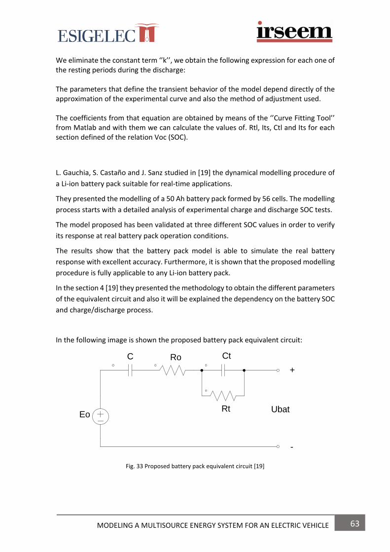
63 MODELING A MULTISOURCE ENERGY SYSTEM FOR AN ELECTRIC VEHICLE
We eliminate the constant term ‘’k’’, we obtain the following expression for each one of the resting periods during the discharge: The parameters that define the transient behavior of the model depend directly of the approximation of the experimental curve and also the method of adjustment used. The coefficients from that equation are obtained by means of the ‘’Curve Fitting Tool’’ from Matlab and with them we can calculate the values of. Rtl, Its, Ctl and Its for each section defined of the relation Voc (SOC).
L. Gauchia, S. Castaño and J. Sanz studied in [19] the dynamical modelling procedure of
a Li-ion battery pack suitable for real-time applications.
They presented the modelling of a 50 Ah battery pack formed by 56 cells. The modelling
process starts with a detailed analysis of experimental charge and discharge SOC tests.
The model proposed has been validated at three different SOC values in order to verify
its response at real battery pack operation conditions.
The results show that the battery pack model is able to simulate the real battery
response with excellent accuracy. Furthermore, it is shown that the proposed modelling
procedure is fully applicable to any Li-ion battery pack.
In the section 4 [19] they presented the methodology to obtain the different parameters
of the equivalent circuit and also it will be explained the dependency on the battery SOC
and charge/discharge process.
In the following image is shown the proposed battery pack equivalent circuit:
Fig. 33 Proposed battery pack equivalent circuit [19]
Eo
C Ro
Rt
Ct
Ubat
+
-

64 MODELING A MULTISOURCE ENERGY SYSTEM FOR AN ELECTRIC VEHICLE
The determination of the battery model parameters from the previous circuit is:
Model Voltage Eo
The model voltage source Eo presents the initial battery open circuit voltage and it is
only measurable at the beginning of the battery cycle. Through the battery simulation,
this value remains constant.
Capacitance C
The capacitance C is obtained from the parameter α, where it represents the slope
between the voltage (∆U) and charge variation (∆Q), and inversely proportional to the
capacitance C.
𝛼 =1
𝐶=∆𝑈
∆𝑄=𝑢1𝑑−𝑢6𝑑
𝑖·∆𝑡
Internal resistance Ro
-Resistance for charge:
𝑅0𝑑1 =𝑢1𝑑−𝑢2𝑑
𝑖
-Resistance for discharge:
𝑅0𝑑2 =𝑢5𝑑−𝑢4𝑑
𝑖
Network Rt-Ct
RC network represents the exponential behaviour produced by electrochemical
processes inside the battery. This voltage variation is described as:
𝑈𝑅𝐶 = ∫1
𝐶𝑡· (𝑖 − 𝑖𝑅𝑡) · 𝑑𝑡
𝑅𝑡𝑑 =𝑢2𝑑−𝑢3𝑑
𝑖
𝐶𝑡𝑑 =𝜏
𝑅𝑡𝑑
Battery terminal voltage Ubat
𝑈𝑏𝑎𝑡 = 𝐸𝑜 −1
𝐶∫ 𝑖 · 𝑑𝑡 − 𝑅𝑜 · 𝑖 − ∫
1
𝐶𝑡· (𝑖 −
∆𝑈𝐶𝑡
𝑅𝑡) · 𝑑𝑡

65 MODELING A MULTISOURCE ENERGY SYSTEM FOR AN ELECTRIC VEHICLE
L.Gauchia, S. Castaño, D. Serrano and J. Sanz [39] explain the influence of BMS (Battery
Management System) on the Characterization and modeling of series and parallel Li-Ion
packs.
The study made by these authors analyse the effects of a BMS (battery management
system) on the characterization and modelling of series and parallel connections of Li-
ion cell packs.
The model proposed consists in four series modules connected in parallel. This model
has been characterized by means of charge, discharge and frequency tests. The results
of the test allow us to determine the parameters of the battery at issue. A comparison
between the model considering the effects of a BMS and a model based on a single-cell
approach is made. As a conclusion, authors say that the experimental results show that
the single cell based approach gives poor results in comparison with a model which
considers BMS effects.
The electric circuit used to simulate the behaviour of the battery pack is shown in the
following figure:
Fig. 34 Battery pack electric circuit [39]
In order to determine which model has better accuracy, the experimental voltage at
battery pack terminals has been compared with the voltage response of the models
calculated above.
This experimental comparison has been performed using a hardware-in-the-loop (HIL)
simulation that represents the battery power demanded by an electric vehicle. HIL
simulation is extensively used to test electric and mechanic systems because real devices
are replaced by their models and lab equipment can be used [39].
C1 C2 C3Ro
R1 R2 R3
VDC
+
-
U pack
i pack

66 MODELING A MULTISOURCE ENERGY SYSTEM FOR AN ELECTRIC VEHICLE
5.1.3 MODELLING OF NICKEL METAL HYDRIDE BATTERIES
Kuhn, Forgez and Friedrich [40] proposed two models using an equivalent electric
scheme to identify the components of the model at issue by means of the technique
called “Electrochemical Impedance Spectroscopy” (EIS). The first model is a dynamic
model used to calculate the voltage responses of the battery when submitted to any
current profile. In contrast, the second model is the energetic model, which is used to
energetic applications. It gives Joule losses during energetic transfers and is also used
for instantaneous power and energy calculations.
There are two models found in battery modelling.
On one hand, the electrochemical phenomena are described in the form of differential
equations and then solved.
On the other, the equivalent electrical circuit is proposed to determine its components
by means of experimental measures.
This method has been used for the modelling of lead-acid batteries as we seen before
in [31], [32], [33], [34], [35], [36]. However, it is rarely applied to NiMH cells.
In this article, Kuhn, Forgez and Friedrich [40] study a dynamical model of a NiMH
battery.
Dynamic model of the NiMH pack
In the following image is considered the equivalent electric circuit for a single NiMH
element:
Fig. 35 Equivalent electric scheme of a single 1.2V 13.5Ah NiMH cell [40]
R
Rtc
Cdl
A B
Zw(s)Eeq

67 MODELING A MULTISOURCE ENERGY SYSTEM FOR AN ELECTRIC VEHICLE
This scheme has been obtained from previous works of P.H.L Notten [41] and E. Kuhn
[42].
We can find the following electrical elements representing either a static or a dynamic
electrochemical phenomenon:
Eeq: equilibrium potential of the cell
Rtc and Cdl: charge transfer phenomena occurring in high frequencies
Zw: diffusion phenomena occurring in low frequencies. This equivalent
impedance is called “Warburg impedance”.
Spectroscopy measurements were made at different State of Charges (SOC), to find the
structure of the impedance Zw.
Energetic model of the NiMH pack
Power and energy losses during energetic transfers can be obtained by calculating
entropy variations.
For determine the Joule losses in an easier way, it can be represented the studied cell
by an equivalent circuit only made of resistive and capacitive elements [40].
Kuhn [40] explains how to deduce the expressions of R and C depart from the
comparison of the equations outlined in (10) and (11) and with the parameters k1 and
k2 identified from Spectroscopy.
Hence, he explains how to obtain the expression of the equation in (12), that is the
“Zw(s)” (Warburg impedance), by calculating the Laplace transform of the equation in
(11). The new equation corresponds to an infinite sum of RC circuits whose equivalent
circuit is shown in the following image:
Fig. 36 Warburg impedance under the form of n RC networks [40]
Zw(s)
C
R1
C
R2
C
Rn
n RC circuits

68 MODELING A MULTISOURCE ENERGY SYSTEM FOR AN ELECTRIC VEHICLE
Kuhn explains that if it is added to the previous electric circuit the equilibrium potential
Eeq, the internal resistance RΩ and the Rtc Cdl network related to charge transfer
phenomena, we get the energetic model of a single NiMH element in time domino as it
is represented in the next image:
Fig. 37 Energetic model of a single Ni MH cell [40]
Kuhn [40] also explains how to calculate the Joule losses of a single element. The
expression is shown in (14).
As a conclusion of the study realized, we can say that using Impedance Spectroscopy for
characterizing battery dynamics is a powerful tool.
With this method, two constants battery models have been defined.
On one hand, the first one was based on non-integer derivatives which was dedicated
to dynamic applications it is a good representation of diffusion phenomena.
On the other, the second method was dedicated to energetic calculations, in order to
define battery efficiency during charge and discharge operations.
Tarabay and Karami [43] studied the structure, the components and the internal
reactions that occur inside the Nickel Metal Hydride (Ni-MH) batteries.
They have also studied the chemical reactions inside the Ni-MH batteries as well as the
most important applications of these kind of batteries in the industry field. Furthermore,
they discuss an electric circuit model of Ni-MH battery.
In the fourth section [43], the specifications and applications are discussed. Some of the
applications of these kind of batteries are the electric plug-in vehicles, hybrid vehicles,
robots, cell phones, laptop computers, calculators, walkie-talkies, photographic and
video equipment, flashlights, portable printers, GPS systems, cordless mouse and
keyboard.
V diff (t)
RΩ i(t) Vn (t) V2 (t) V1 (t) Vtc (t)
R
C
R1
C
R2
C
Rn
Cdl
RtcA
Eeqi (t)
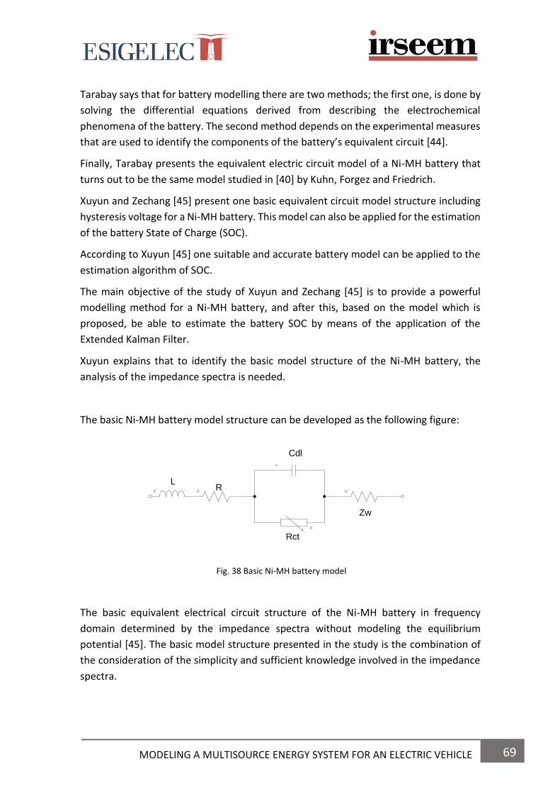
69 MODELING A MULTISOURCE ENERGY SYSTEM FOR AN ELECTRIC VEHICLE
Tarabay says that for battery modelling there are two methods; the first one, is done by
solving the differential equations derived from describing the electrochemical
phenomena of the battery. The second method depends on the experimental measures
that are used to identify the components of the battery’s equivalent circuit [44].
Finally, Tarabay presents the equivalent electric circuit model of a Ni-MH battery that
turns out to be the same model studied in [40] by Kuhn, Forgez and Friedrich.
Xuyun and Zechang [45] present one basic equivalent circuit model structure including
hysteresis voltage for a Ni-MH battery. This model can also be applied for the estimation
of the battery State of Charge (SOC).
According to Xuyun [45] one suitable and accurate battery model can be applied to the
estimation algorithm of SOC.
The main objective of the study of Xuyun and Zechang [45] is to provide a powerful
modelling method for a Ni-MH battery, and after this, based on the model which is
proposed, be able to estimate the battery SOC by means of the application of the
Extended Kalman Filter.
Xuyun explains that to identify the basic model structure of the Ni-MH battery, the
analysis of the impedance spectra is needed.
The basic Ni-MH battery model structure can be developed as the following figure:
Fig. 38 Basic Ni-MH battery model
The basic equivalent electrical circuit structure of the Ni-MH battery in frequency
domain determined by the impedance spectra without modeling the equilibrium
potential [45]. The basic model structure presented in the study is the combination of
the consideration of the simplicity and sufficient knowledge involved in the impedance
spectra.
LR
Cdl
Rct
Zw

70 MODELING A MULTISOURCE ENERGY SYSTEM FOR AN ELECTRIC VEHICLE
We can see some similarities with the model presented by Kuhn and Forgez in [40].
Finally, based on the impedance-based model structure and Ni-MH battery hysteresis
phenomenon test behaviours, one equivalent circuit model including the hysteresis
voltage model is presented in the following figure [45]:
Fig. 39 Equivalent circuit model for the Ni-MH battery [45]
In the figure, one hysteresis voltage model Vh was included in the part of Voc. The
inductive element L hasn’t been included in the model since the Ni-MH batteries are less
used at so high frequencies. Besides, the authors used one linear resistor paralleled with
the capacitor in the model and they need the further investigation on the non-linear
resistor in the future work. Any other else electric elements in the model are the same
as the explanations of pre-provided impedance-based model.
The hysteresis voltage model can be described as the equations outlined in (1) for charge
and (2) for discharge.
In the IV section it is explained the estimation of SOC of the Ni-MH battery by means of
the Extend Kalman-Filter (EKF) method.
So, as a conclusion, the method studied by these authors can model the dynamic
behaviour of the battery which makes it suitable for Electric and Hybrid Electric Vehicle
applications.
Voc
Vt
Uo Co R
Rct
Cd
Zw
I
Vh
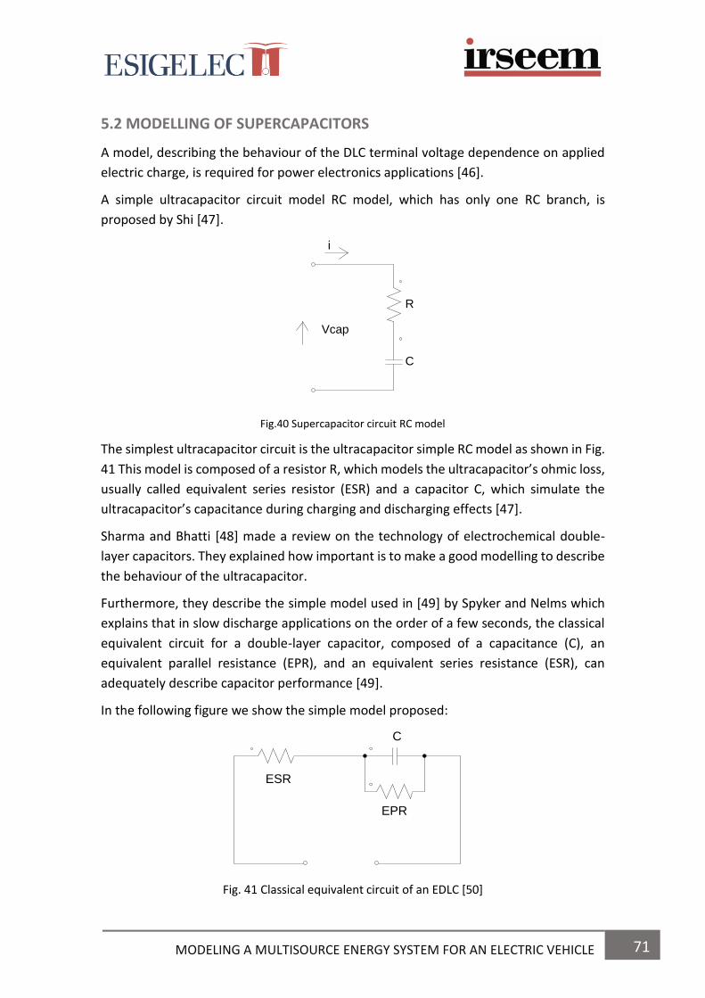
71 MODELING A MULTISOURCE ENERGY SYSTEM FOR AN ELECTRIC VEHICLE
5.2 MODELLING OF SUPERCAPACITORS
A model, describing the behaviour of the DLC terminal voltage dependence on applied
electric charge, is required for power electronics applications [46].
A simple ultracapacitor circuit model RC model, which has only one RC branch, is
proposed by Shi [47].
Fig.40 Supercapacitor circuit RC model
The simplest ultracapacitor circuit is the ultracapacitor simple RC model as shown in Fig.
41 This model is composed of a resistor R, which models the ultracapacitor’s ohmic loss,
usually called equivalent series resistor (ESR) and a capacitor C, which simulate the
ultracapacitor’s capacitance during charging and discharging effects [47].
Sharma and Bhatti [48] made a review on the technology of electrochemical double-
layer capacitors. They explained how important is to make a good modelling to describe
the behaviour of the ultracapacitor.
Furthermore, they describe the simple model used in [49] by Spyker and Nelms which
explains that in slow discharge applications on the order of a few seconds, the classical
equivalent circuit for a double-layer capacitor, composed of a capacitance (C), an
equivalent parallel resistance (EPR), and an equivalent series resistance (ESR), can
adequately describe capacitor performance [49].
In the following figure we show the simple model proposed:
Fig. 41 Classical equivalent circuit of an EDLC [50]
R
C
i
Vcap
ESR
EPR
C

72 MODELING A MULTISOURCE ENERGY SYSTEM FOR AN ELECTRIC VEHICLE
Spyker explains that the classical equivalent circuit of Fig.42 is comprised of three
components: the capacitance (C), the ESR, and the equivalent parallel resistance (EPR).
The ESR is a loss term that models internal heating in the capacitor and is therefore of
most importance during charging and discharging. It also will reduce terminal voltage
during discharge into a small load resistance due to the resistive divider effect. The EPR
models a current leakage effect and will therefore impact long-term energy storage
performance [49].
In the following sections, Spyker tells about the determination of the capacitance, the
EPR and the ESR for the previous equivalent circuit.
However, according to Zubieta and Bonert [46], a first approach using a simple resistive
capacitive model (series RC circuit) demonstrates that this approach is insufficient.
“They propose an equivalent circuit to describe the measured terminal behaviour of SC.
This model is able to follow measured SC characteristics more precisely. They also
present a method to identify the parameters of the proposed model’’ [46].
The following image represents the equivalent circuit proposed by Zubieta and Bonert:
Fig. 42 Equivalent circuit model for a DLC [46]
This model describes the terminal behaviour of the DLC over the range of 30 min with
sufficient accuracy.
In the model, the resistive element represents the resistivity of the materials forming
the double-layer charge distribution. The capacitive element represents the capacitance
between the two materials [46].
Rd R1
Rlea
Ri
Cd C1
C11C12
Vt
Vci
Ci1*VciCio
+
-

73 MODELING A MULTISOURCE ENERGY SYSTEM FOR AN ELECTRIC VEHICLE
Zubieta and Bonert proposed a circuit model with three well distinct RC time constants.
The choice of three branches is the least number, if good accuracy is wanted for the
specified time range of 30 min. Each of the three branches has a disctinct time constant.
The first or immediate branch, Ri, Ci0, and the voltage-dependent capacitor Ci1,
dominates the immediate behaviour of the DLC in the time range of seconds in response
to a charge action. The second or delayed branch, with parameters Rd and Cd,
dominates the terminal behaviour in the range of minutes. Finally, the third or long-term
branch, with parameters Rl and Cl, determines the behaviour for times longer than 10
min [46].
Besides, the first branch is modelled as a voltage-dependent differential capacitor. The
differential capacitor consists of a fixed capacitance Ci0 and a voltage-dependent
capacitor Ci1*V [46].
A leakage resistor, parallel to the terminals, is added to represent the self-discharge.
In the following sections, Zubieta and Bonert explain the determination of the
parameters of the equivalent circuit. It is due because the three branches of the circuit
have different time constants. In the section IV, the performance of each branch is
explained accurately.
Some other authors, as F. Rafik [51], Sharma and T.S. Bhatti [48], demonstrate why the
traditional models used to explain capacitor behaviour during charging and discharging
are not adequate for the electrochemical double layer capacitor.
On one hand, Rafik [51] propose an electrical model made of 14 RLC elements for
describing the supercapacitor behaviour. These elements, have been determined from
experimental data using electrochemical impedance spectroscopy (EIS) applied on
supercapacitors [51]. He also makes a comparison from the experimental results
obtained during charge and discharge process of supercapacitor.
On the other, Sharma and Bhatti [48] made a review explaining what the technology of
ultracapacitors involves: history, classification, construction, modelling, testing, voltage
balancing of the EDLC, the applications of EDLC and their advantages over other storage
technologies [48].
In the modelling section of supercapacitors in [48], there are explained three different
models: the classical equivalent circuit, as we saw before in [49] explained by Spyker; a
three branch model explained by Zubieta and Bonert in [46], and finally, porous
electrodes as transmission lines explained by Levie in [52].
Kaus and Kowal [53] establish a complex electrical model to account for the
redistribution effects of ions occurring in supercapacitors [53].

74 MODELING A MULTISOURCE ENERGY SYSTEM FOR AN ELECTRIC VEHICLE
So, we can affirm that a considerable amount of charge always remains stored inside
the SC during its normal use, even after fast discharge.
J.V. Mierlo, P.V. Bosscche and G. Maggetto [28] made one study about the different
models of energy sources for the Electric and Hybrid Electric vehicles such as fuel cells,
batteries and ultracapacitors for simulating them and study power flows in vehicle drive
trains as well as compare some different drive trains topologies.
In the fourth section [28] they present an equivalent circuit of an ultracapacitor, as we
show in the following image:
Fig. 43 Ultracapacitor equivalent circuit [28]
5.3 MODELLING OF FUEL CELLS
A. D. Le and B. Zhou [54], explain us that a complete mathematical model is necessary
to characterize more fully the physical behaviour, to aid our understanding of complex
phenomena occurring in a fuel cell system and to provide powerful tools for fuel cell
design and optimization [54].
In their study, they construct a general model of a PEMFC (Proton Exchange Membrane
Fuel Cell). Then, this model was implemented and employed to simulate the fluid flow,
heat transfer, species transport, electrochemical reaction and current density
distribution, especially focusing on liquid water effects on PEMFC performance.
The results of the study made by A.D. Le and B. Zhou [54], showed that the general
model of PEMFC can be a useful tool for the optimization of practical engineering
designs of PEMFC.
Ri
CUcap Uc
Rp
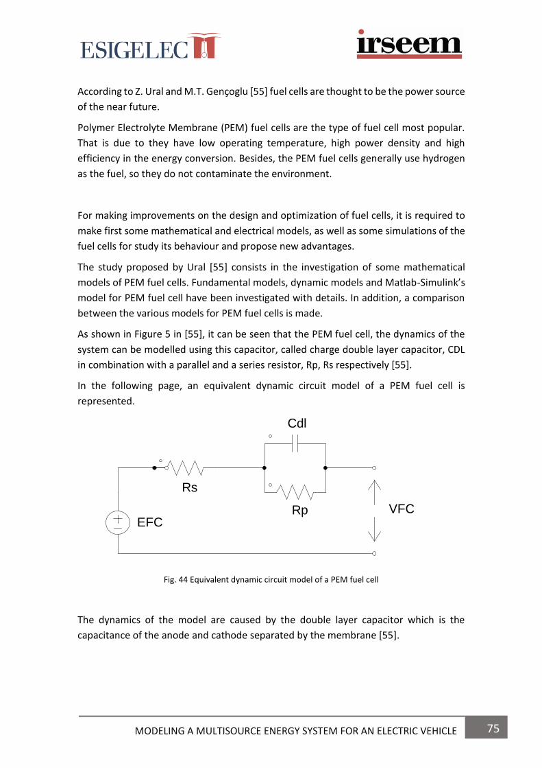
75 MODELING A MULTISOURCE ENERGY SYSTEM FOR AN ELECTRIC VEHICLE
According to Z. Ural and M.T. Gençoglu [55] fuel cells are thought to be the power source
of the near future.
Polymer Electrolyte Membrane (PEM) fuel cells are the type of fuel cell most popular.
That is due to they have low operating temperature, high power density and high
efficiency in the energy conversion. Besides, the PEM fuel cells generally use hydrogen
as the fuel, so they do not contaminate the environment.
For making improvements on the design and optimization of fuel cells, it is required to
make first some mathematical and electrical models, as well as some simulations of the
fuel cells for study its behaviour and propose new advantages.
The study proposed by Ural [55] consists in the investigation of some mathematical
models of PEM fuel cells. Fundamental models, dynamic models and Matlab-Simulink’s
model for PEM fuel cell have been investigated with details. In addition, a comparison
between the various models for PEM fuel cells is made.
As shown in Figure 5 in [55], it can be seen that the PEM fuel cell, the dynamics of the
system can be modelled using this capacitor, called charge double layer capacitor, CDL
in combination with a parallel and a series resistor, Rp, Rs respectively [55].
In the following page, an equivalent dynamic circuit model of a PEM fuel cell is
represented.
Fig. 44 Equivalent dynamic circuit model of a PEM fuel cell
The dynamics of the model are caused by the double layer capacitor which is the
capacitance of the anode and cathode separated by the membrane [55].
EFC
Rs
Cdl
Rp VFC

76 MODELING A MULTISOURCE ENERGY SYSTEM FOR AN ELECTRIC VEHICLE
The small-signal model will have a double layer capacitor dominating a part of the
frequency domain.
All electrode-material systems have a geometrical capacitance C∞ and a bulk resistor
R∞ in parallel, leading to the dielectric relaxation time of the basic material. RDL is a
reaction resistor [55].
Fig. 45 Small signal equivalent circuit model of PEM fuel cell [55]
Finally, a matlab-simulink model is made in the following section [55].
C. Raymond [56] makes one study on the mechanisms that take place in the cathode
Gas Diffusion Layer (GDL) of a Hydrogen-Oxygen Proton Exchange Membrane (PEM)
Fuel Cell. Within a Gas Diffusion Membrane, transport of liquid water, water vapour,
oxygen, nitrogen and heat are the main processes taking place.
The goals on the study are:
- The numerical solution of the scaled two-dimensional problem
- The validation of the one-dimensional solutions
- An analysis of the anisotropic nature of the membrane
- A better treatment of the temperature and pressure along the layer
Raymond says that for some particular choices, the distribution of oxygen along the
layer appears to be more efficient as compared to the isotropic case [56].
EFC
Roo
Cdl
RDL VFC
Coo
Z
C∞
C ∞

77 MODELING A MULTISOURCE ENERGY SYSTEM FOR AN ELECTRIC VEHICLE
CHAPTER 3 6. PHOTOVOLTAIC SYSTEMS FOR EV

78 MODELING A MULTISOURCE ENERGY SYSTEM FOR AN ELECTRIC VEHICLE
6. PHOTOVOLTAIC SYSTEMS FOR ELECTRIC VEHICLES
6.1 HOW TO INSTALL SOLAR PANELS IN ELECTRIC VEHICLES
Using renewable energies means to make a lower use of natural resources such as oil, coal or natural gas. So, if we apply renewable energies to electric vehicle applications we will contribute to create an environment more sustainable.
Although we know that electric cars are connected into the network for charging the energy storage system they are using, we have to know that there exist other systems which can be used to charge them, such as photovoltaic systems.
This has been one of the last breakthroughs into the automotive industry: the
installation of solar panels for charging the batteries of EVs. This installation can be done
either in the roof of buildings or in the roof of the car itself.
First of all, we have to know that a photovoltaic system is a device which converts solar
energy into electricity.
On one hand, we can make the installation of solar panels in the roof of buildings. This
application would be very practical in places where the car is parked during a lot of time,
such as workplaces, parking lots of supermarkets, airports, etc. By this way, the energy
stored into the battery’s cars could be for using it after, and the excess of the energy
could be injected into the grid to supply energy into the same buildings or businesses.
In the following image we can see the application of this technology presented by G.R.
Chandra Mouli, P. Bauer and M. Zeman in [57]:
Fig. 46 Design of solar powered EV charging station [57]
The study they have done investigates the possibility of charging battery electric vehicles at
workplace in Netherlands using solar energy [57].

79 MODELING A MULTISOURCE ENERGY SYSTEM FOR AN ELECTRIC VEHICLE
Solar energy into EVs would means a significant addition to the car’s autonomy, beyond
supporting air conditioning and gadgets. According to Toyota engineers, installing these
devices on a car could provide around ten kilometres of autonomy a day [58].
The latest solution presented by Panasonic will be released on the Toyota Prius plug-in,
initially commercialized in Japan. It is a solar cell- in option for about 3.000 euros - which
offers 180W: in the best conditions it could produce an additional range of three
kilometres daily [58].
Fig. 47 Installation of solar panels on the roof of an EV
Moreover, a group of designers and engineers who are part of a group called ‘’Solar
team” at the University of Technology of Eindhoven, have suggested a project called
“Stella Vie” which is a completely solar and family car that obtains its energy through
solar panels. Furthermore, it is accessible to the general public due to it is aimed at
middle-class families [59].
The car has been designed with a solar panel roof, which will allow it to have up to 1000
kilometres of autonomy during a sunny day in Netherlands. In addition, the Stella Vie is
capable of storing all the excess of energy in a battery that has inside, which can be used
to power any room in our house or any electrical appliance (Vehicle-to-home) [58].
On the other hand, we can make the installation on the roof of an Electric Vehicle. This
application consists in taking the energy provided from the sun, which is a natural
source, and supply it into the energy storage systems that the car is using such as
batteries, supercapacitors and fuel-cells. After this, the energy will be used to power the
electric engine.

80 MODELING A MULTISOURCE ENERGY SYSTEM FOR AN ELECTRIC VEHICLE
For making the implementation feasible, we have to make sure that this type of
installation in an EV will supply enough energy to recharge its own batteries. But, how
we do that?
Here below, we have made an estimation about how many solar panels will a building
need to recharge the battery pack of an EV which is supposed to have 100 Km of
autonomy per day.
First of all, we have to predict that for having 100 km per day of autonomy we will need 21 kWh of battery. So we need to achieve that the solar panels we are going to install on the roof of the building will generate this quantity of energy to could charge the batteries of the EV. Secondly, we have to be aware about the locality where we are going to make the installation because the irradiation of the sun varies depending on the area where it is done. So, we have to know the irradiation of the sun in the area that we are going to make the installation. We can search this data in some weather research centres on the internet. In this estimation, the irradiation of the sun is 7 kWh/m2. Once we know the irradiation, we have to be aware that in summer will be different than in winter. Besides, if the lines of the sun are perpendicular, the solar panel is capable to transform its nominal value. So, in the case where areas have low sunlight, we could install solar trackers, to make the panels turn as the same time as the sun does. By this way we can reduce the loss factor, but it makes the installation expensive. Furthermore, we have to be aware that we will have a loss factor, in our case 70%, that may be of importance for determining the calculation of the installation.
Until here, we have:
• irradiation = 7kWh/m2 diary
• Download = 21000 Wh/day
• Factor of loss = 1.7 (70%) Therefore, to make a simulation of the calculation we use the following equations:
Power in panels = (1.7 x 21000) / 7 = 5100 W
Moreover, if we put panels of 300 W for example, we only have to divide the quantity of power between 300 to know how many panels do we need. So:
Number of panels = 5100 / 300 = 17 panels

81 MODELING A MULTISOURCE ENERGY SYSTEM FOR AN ELECTRIC VEHICLE
We could do the same installation with less solar panels but we wouldn’t achieve the value that we need for charging the battery of our electric vehicle to make 100 km per day. As we can see, we supposed that for making 100 km per day with the EV, we needed to provide 21 kWh of energy to charge its batteries, and that means, according to the previous calculations, to install 17 panels. If each one of the panels costs from 200 $ to 400 $, for the whole installation it will costs from 3500$ to 7000$. So as a conclusion, we can see that this kind of installation for only one car will be too expensive, because it means to increase from 3500$ to 7000$ the price of the electric car [60].
Moreover, the excess of energy that the solar panels will generate in the EV could be
injected into the grid, houses or buildings to provide more energy into them and by
this way avoid to use fossil fuels.
6.2 MODELLING OF A PHOTOVOLTAIC SYSTEM FOR E.V
Wang and Yue [61] present a generic approach for PV panel modelling. For making the
modelling, the data could be obtained from the manufacturer datasheet.
In the study, Wang presents a two-stage power conversion system (PCS) which is
adopted for the PV generation system and a Battery Energy Storage System (BESS) can
be connected to the dc-link through a bi-directional dc/dc converter.
Finally, a comparison about the performance of the integrated BESS and PV generation
is made using PSCAD and Matlab. The effectiveness of the controller is also validated
from the results obtained in the previous simulations.
The aim of the study made by Wang and Yue [61] is based on the function of the BESS
to store the solar power during a fault condition. Therefore, this allows the grid-
connected inverter to provide voltage support and ride while there is a fault event.
In the section III [61] the modelling of the solar power generation and the battery energy
storage system is explained.
Based on the data obtained from the manufacturers datasheet, a generic solar
generation model is developed to include the solar irradiance and temperature.
Generally, a solar module is made by connecting in series a number of solar cells. A solar
array is then a number of solar modules connected in series and parallel.
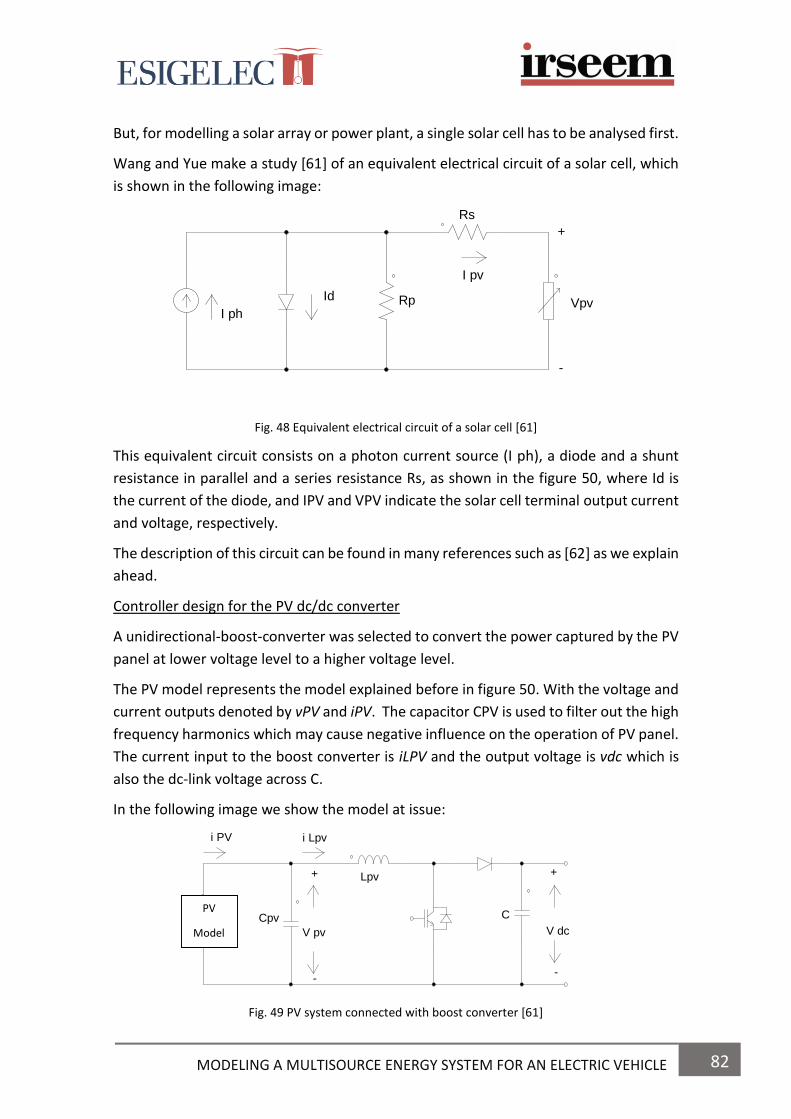
82 MODELING A MULTISOURCE ENERGY SYSTEM FOR AN ELECTRIC VEHICLE
But, for modelling a solar array or power plant, a single solar cell has to be analysed first.
Wang and Yue make a study [61] of an equivalent electrical circuit of a solar cell, which
is shown in the following image:
Fig. 48 Equivalent electrical circuit of a solar cell [61]
This equivalent circuit consists on a photon current source (I ph), a diode and a shunt
resistance in parallel and a series resistance Rs, as shown in the figure 50, where Id is
the current of the diode, and IPV and VPV indicate the solar cell terminal output current
and voltage, respectively.
The description of this circuit can be found in many references such as [62] as we explain
ahead.
Controller design for the PV dc/dc converter
A unidirectional-boost-converter was selected to convert the power captured by the PV
panel at lower voltage level to a higher voltage level.
The PV model represents the model explained before in figure 50. With the voltage and
current outputs denoted by vPV and iPV. The capacitor CPV is used to filter out the high
frequency harmonics which may cause negative influence on the operation of PV panel.
The current input to the boost converter is iLPV and the output voltage is vdc which is
also the dc-link voltage across C.
In the following image we show the model at issue:
Fig. 49 PV system connected with boost converter [61]
Lpv
Cpv C
V pv
+
--
+
V dc
i Lpvi PV
PV
Model
RpId
I ph
I pv
Rs
+
-
Vpv

83 MODELING A MULTISOURCE ENERGY SYSTEM FOR AN ELECTRIC VEHICLE
As a conclusion of the study in [61] we can say that the study was about a battery energy
storage system incorporated to a PV.
So, the battery stores the power generated by the PV plant. In case of fault, the system
could continue operating during its duration.
Other authors in [62], S. Kim, J. Jeon, C. Cho, E. Kim and J. Ahn presented the modelling
and simulation of a grid-connected photovoltaic system (GSPS) to analyse its grid
interface behaviour and control performance in the system design.
In the second section of [62] they present a configuration of a three phase GCPS (Grid-
connected photovoltaic system).
This system consists in a PV array, a diode, a dc-link capacitor, a voltage source inverter
(VSI) with a harmonic reduction filter, a step-up transformer and a power grid.
This system is not applied to the EVs, but its operation will help us to have a better
understanding of the PV module.
DC power generated from the solar array charges the dc-link capacitor. The grid
connection inverter turns the dc into ac power, which has a sinusoidal voltage with the
same frequency as the utility grid. The diode blocks the reverse current flow through the
PV array. The transformer steps up the VSI voltage to the nominal value of the power
grid and providing electrical isolation between the PV system and electric network. The
filter eliminates the harmonic components [62].
In the following image we show the model presented in [62]:
Fig. 50 Modelled GCPS [62]
In the following section, (3) in [62], it is explained the performance of each element of
the GCPS model in which we can find the PV array, the grid connection inverter and the
power control of GCPS. However, we are going to explain only the performance of the
PV array.
PV PCS
FILTER
VSI
DC link
PV Array TRPower Grid

84 MODELING A MULTISOURCE ENERGY SYSTEM FOR AN ELECTRIC VEHICLE
PV Array
For modelling the solar cell, a simplified equivalent circuit model is proposed to make
our work easier due to it is simpler to implement and study the electrical behaviour.
PV modules are manufactured by connecting a number of PV cells in series. A solar array
is made of a number of solar modules connected either in series or parallel.
Generally, for understanding the performance of a PV array, it is commonly used the
modelling of a PV module since the equivalent circuit model allows us to have a better
understanding of its performance.
In the following figure, it is shown the equivalent circuit model of a PV module:
Fig. 51 Equivalent circuit of a PV module
This circuit model is composed of an ideal current source, a diode connected in parallel
with the current source and a series resistor.
For modelling a PV module, the following parameters are required to be determined:
-I: the output terminal current
-Isc: short circuit current of a module under a given solar irradiance
-Id: diode current
-Rs: series resistance which represents the intrinsic resistance to the current
flow
All these parameters can be directly calculated from the manufacturer’s data or
deduced by solving the equations (1) - (6) explained by Kim in [62].
Rs
Solar Module
Id
I
+
-
V
Isc

85 MODELING A MULTISOURCE ENERGY SYSTEM FOR AN ELECTRIC VEHICLE
Another authors such as R. Mkahl, A. Nait-Sidi-Moh, M. Wack studied the modelling,
sizing and control of a photovoltaic stand-alone application that can charge the BEV at
home. This application is also known as Vehicle-to-home. They also represent the
modelling approach and mathematical models that describe the system components.
Finally, they comment some simulations and experimental results made in [63].
Fig. 52 EV charging / discharging: H2V2H structure [63]
In a H2V system, the EV could be charged with direct current from photovoltaic panels
(PV) or with current from a Lead-Acid battery installed at home (see Fig. 54). Moreover,
this system can provide energy in the opposite direction, from the vehicle to the house
when it is required (V2H). The study of both processes (H2V and V2H) requires adequate
models in order to make an optimal energy management and effective usage of the
system components. This modelling is based on mathematical equations in order to
observe the behaviour of the system.
Mkahl says that many parameters such as the state of charge (SOC), time of charging
and discharging, current of charging and discharging should be taken into account during
charging and discharging processes [63].
In their paper, they introduce the ESS and present the modelling approach of a PV and
a Lead-acid battery as well as DC/DC converter topologies. After this, they make a
system sizing and some comparisons between the simulation results, experimental
results and datasheet.
On their study they present the main components of a charging station. So, they
present the PV modelling, the Lead-acid battery and the DC/DC converter.

86 MODELING A MULTISOURCE ENERGY SYSTEM FOR AN ELECTRIC VEHICLE
PV Modelling
Different researchers have studied the mathematical modelling of the PV cell. For
example, a model of the photovoltaic cell with double diode is developed in [64] by
Abdallah Zegaoui.
However, in the study of R. Mkahl, it is used a single-model PV cell in order to formalize
the PV solar cell. This model was previously presented in other research work [65] by E.
Mboumboue. The equivalent electrical circuit is represented in the following image:
Fig. 53 Equivalent circuit of a solar cell [63]
Here, the diode represents the cell behaviour while being in darkness. Two resistances,
shunt and series resistance are added to present internal losses. The current-voltage (I-
V) equation can be simplified by considering the shunt resistance as infinity [63].
The equation of PV module which expresses the characteristic current–voltage (I-V) of
PV module is given as follow [63]:
𝐼𝑃𝑉(𝑡) = 𝑛𝑝 ×
(
𝐼𝐿(𝑡) − 𝐼𝑜 [𝑒𝑥𝑝(
𝑞 (𝑉(𝑡) +𝐼𝑚(𝑡)𝑅𝑆𝑚𝑛𝑃
)
𝑛𝑠 × 𝑛𝑘𝑇) − 1] − (
𝑉(𝑡) + 𝐼𝑚(𝑡)𝑅𝑠𝑚𝑛𝑃 × 𝑅𝑆𝐻𝑚
)
)
Where:
n: diode ideality factor (1 for an ideal diode);
ns: cells in series
np: cells in parallel;
Im: current of PV module;
V: voltage of PV module;
Rsm: series resistance of PV module;
RSHm: shunt resistance of PV module;
IL: photovoltaic current;
Io: reverse saturation current;
𝐾𝑇
𝑞 : terminal potential (0.0259V at 25C°).
Rsh
Rs
I LID ISH
I
V

87 MODELING A MULTISOURCE ENERGY SYSTEM FOR AN ELECTRIC VEHICLE
Battery model
As we saw in the chapter 2, there are three different ways to classify the battery
models:
-Electrochemical model
-Mathematical model
-Electric model
DC/DC Charger topologies
Solar energy is converted to electric energy by means of the PV panels. This electric
energy is after used to recharge Lead-Acid batteries via DC/DC Boost converter (see Fig.
56 (a)). Boost converter is controlled by maximum power point tracking algorithm
(MPPT) for obtaining always the PV maximum power at PV panel output [63].
Moreover, a Buck- Boost (current-bidirectional converter) is used for charging the Li-Ion
battery into the EV from home energy (H2V). However, this converter can work in the
opposite direction, that means to charge the Lead-acid batteries inside the house from
the vehicle battery (V2H). The Fig. 56 (b), correspond to a DC-DC current bidirectional
converter.
(a) Boost (b) Buck-boost
Fig. 54 DC-DC charger topologies
As a conclusion of their work [63], they have obtained that batteries Li-Ion can be
charged promptly from the current of Lead-Acid batteries using buck/boost converter.
Nowadays, graphene is being investigated for a lot of researchers due to its
specifications, reliability and efficiency. It is also being applied into photovoltaic devices
to improve them.
For example, X. Huang and X. Qi studied the advantages of graphene based composites
in some applications such as batteries, supercapacitors and fuel cells. Moreover, they
investigate about the incorporation of graphene into photovoltaic devices such as silicon
based solar cells, polymer based solar cells, dye sensitized solar cells (DSSCs) and
quantum dots-based solar cells [21].
CVpv
DL
S
IL
V bus
L T1
D1
T2
D2
V Li-Ion
V bus
88 MODELING A MULTISOURCE ENERGY SYSTEM FOR AN ELECTRIC VEHICLE
CHAPTER 4 7. SIMULATION RESULTS

89 MODELING A MULTISOURCE ENERGY SYSTEM FOR AN ELECTRIC VEHICLE
7. SIMULATIONS RESULTS
In this section, we represent the simulation of a Hybrid Energy Storage System (HESS)
which is made by the combination of a battery and supercapacitor.
Fig. 55 Schematic of a multisource energy system for simulation
So, as we can see on the image, the system consists in a battery, a supercapacitor, a coupler, a
three-phase inverter, a filter LC, a control via pulse width modulation (PWM) and finally a
synchronous electric motor with rotor coil.
For making the simulation we have used the software PSIM.
The supercapacitor is able to deliver a high power in a short period of time.
The battery is coupled to the supercapacitor, which will be charged usint the energy stored
into the battery. Supercapacitor will be discharged if there is a high acceleration.
Battery
DC Supercapacitor
Coupler
three-phase inverter
Control
PWM
Filter
L C PMSM
ss Synchronous rotor coil
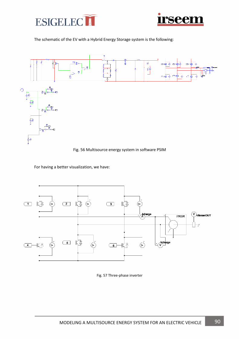
90 MODELING A MULTISOURCE ENERGY SYSTEM FOR AN ELECTRIC VEHICLE
The schematic of the EV with a Hybrid Energy Storage system is the following:
Fig. 56 Multisource energy system in software PSIM
For having a better visualization, we have:
Fig. 57 Three-phase inverter
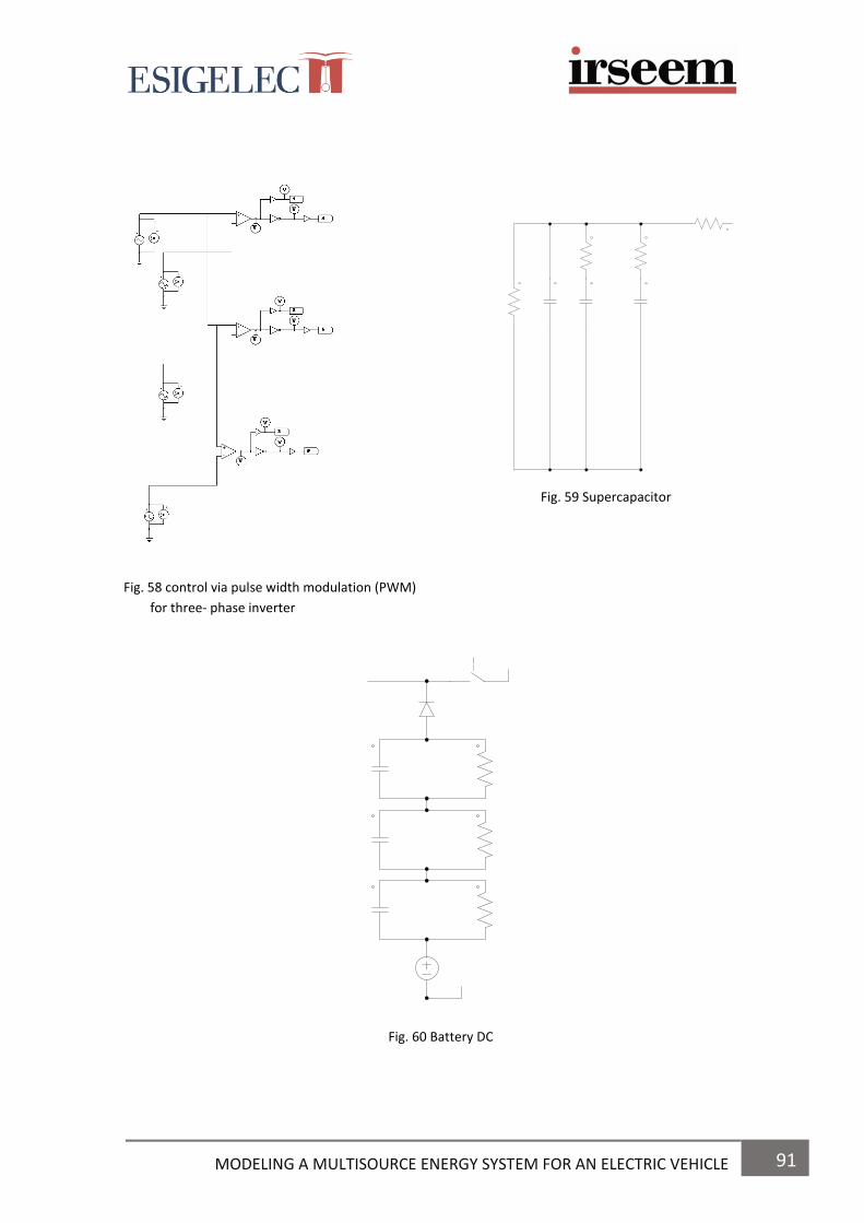
91 MODELING A MULTISOURCE ENERGY SYSTEM FOR AN ELECTRIC VEHICLE
Fig. 59 Supercapacitor
Fig. 58 control via pulse width modulation (PWM)
for three- phase inverter
Fig. 60 Battery DC

92 MODELING A MULTISOURCE ENERGY SYSTEM FOR AN ELECTRIC VEHICLE
The simulation result for the current and voltage of the HESS proposed are:
Fig. 61 Representation of Current Icharge
Fig. 62 Representation of Voltage Vcharge
I charge: 10 A
V charge: 200 V
We have to mention that in this case, it hasn’t been considered any load at the output
of the engine.
Moreover, the energy stored into the supercapacitors and the battery will be used to
power the engine of the EV. However, if the car is not being used because it is parked,
the energy could flow in the opposite direction and by this way, the car could inject the
energy stored into the batteries and supercapacitor to the grid.

93 MODELING A MULTISOURCE ENERGY SYSTEM FOR AN ELECTRIC VEHICLE
CHAPTER 5 8. EV WITH HYBRID ESS
9. CONNECTION BETWEEN THE EV AND THE GRID

94 MODELING A MULTISOURCE ENERGY SYSTEM FOR AN ELECTRIC VEHICLE
8. ELECTRIC VEHICLES WITH HYBRID ENERGY STORAGE SYSTEMS
Nowadays, the main issues of manufacturing Electric vehicles and Hybrid Electric
vehicles are the cost of the components such as the powertrain, batteries, fuel cells,
supercapacitors, engines and also the fuel consumption, the emissions and the vehicle
performance.
However, since years ago the automotive industry, research institutes and engineers are
developing new technologies by means of simulation models and tests in order to
improve the vehicle performance.
In this section we are going to explain several studies that some researchers have done
during last years about the combination of different energy storage systems for
improving the performance and autonomy of electric and hybrid vehicles. These systems
are called hybrid energy storage systems due to they are the result of combining two or
more different energy storage systems.
This new system would be the flawless because it would provide the best specifications
of each energy storage system, and as a result we will improve the efficiency and
autonomy of the electric car.
J. Bauman and M. Kazerani [50] proposed a study to compare three different
configurations for vehicles: fuel-cell-battery (FC/B), fuel-cell-ultracapacitor (FC/SC), and
fuel-cell-battery-ultracapacitor (FC/B/SC). The aim of their study is to compare the
performance, fuel economy and powertrain cost between all three configurations by
means of some simulations in Matlab/Simulink.
The conclusions from the simulations made on their study are:
1. Fuel cells are relatively expensive in comparison to batteries and
supercapacitors.
2. The choice of the combination of different energy storage systems less
desired is the fuel-cell-ultracapacitor due to the high cost of the power train,
the low fuel economy and a high mass. Moreover, ultracapacitors have low
energy density, efficiency and cost of the lithium-ion batteries.
3. The combination of fuel-cell-battery and fuel-cell-battery-ultracapacitor are
very similar. The less costly system is the fuel-cell-battery but the fuel-cell-
battery-ultracapacitor is the best combination in fuel economy and it also has
low stress so this extend the battery lifetime.

95 MODELING A MULTISOURCE ENERGY SYSTEM FOR AN ELECTRIC VEHICLE
Another study made by L. Gauchia, A. Bouscayrol, J. Sanz, R. Trigui and P. Barrade [66]
represents the modelling and control by means of Energetic Macroscopic
Representation (EMR) of a hybrid system made by the combination of a fuel cell, battery
and supercapacitor for the vehicle application.
The Energetic Macroscopic Representation (EMR) is a graphical tool which is very helpful
when studying complex systems and its energy management. Furthermore, in EMR each
element is represented by a pictogram which internally includes the mathematical
equations that describes the relationship between action and reaction inputs and
outputs [66].
Thus, the vehicle simulated in the study [66] is a 32 Kw fuel-cell-battery-supercapacitor.
Fig. 63 Fuel cell-battery-supercapacitor hybrid electric vehicle [66]
In the following image we show the different equivalent circuits used for the energy
storage systems:
a) b) c)
Fig. 64 (a) Fuel cell equivalent circuit. (b) Battery equivalent circuit. (c) Supercapacitor equivalent circuit. [66]
L Rohm
R1
C1
UFC
iFC
E
Rint
Ubat
R1
C1
R2
C2
C4

96 MODELING A MULTISOURCE ENERGY SYSTEM FOR AN ELECTRIC VEHICLE
The image a) represents the equivalent circuit of the fuel-cell. The voltage E depends on
the stack temperature. The resistances and capacitor voltages represent the ohmic and
double layer capacitance phenomena which take places in the stack.
The fuel cell is connected to the rest of the system via an inductance, to smooth the
current ripple, and a dc-dc converter [66].
The image b) represents the equivalent circuit of the battery model. For the correct
computation of the battery model is necessary to estimate the state-of-charge of the
battery. It can be calculated with the following equation:
𝑆𝑂𝐶𝑡(%) = 𝑆𝑂𝐶𝑡−1(%) −100ᶯ
𝐶𝑛∫𝑖(𝑡)𝑑𝑡
The image c) represents the equivalent circuit of the supercapacitor which includes a
series inductance, capacitance and two RC networks. This model was previously studied
and validated by other authors [67].
Furthermore, other authors present equivalent circuits with different topologies such as
Buller in [68] and Barrade who has proposed three different solutions of a series
connection of supercapacitors for the voltage equalization in [69].
J. V. Mierlo, P. V. Bossche and G. Maggetto make one study [28] about the different
models of energy sources for the Electric and Hybrid Electric vehicles such as fuel cells,
batteries, ultracapacitors, flywheels and engine-generators. The aim of the study is to
simulate and study power flows in the vehicle drive trains as well as compare different
drive trains topologies.
Moreover, the functionality and characteristics of each model used for making the
simulations such as fuel cells, batteries, ultracapacitors, flywheels and engine-generator
units have been explained.
In the section 2, 3 and 4 in [28], J.V. Mierlo and P.V. Bossche represent the models of
the different energy storage systems such as batteries, supercapacitors and fuel cells.
They also explain how to determine the parameters from these models by means of
some equations described through their paper.
So we can see that nowadays, there are a lot of researchers, engineers and scientists
that are investigating new hybrid energy storage systems with large capacity, fast
charging/discharging, long lifetime and low cost in order to provide the best
performance to Electric and Hybrid electric vehicles.

97 MODELING A MULTISOURCE ENERGY SYSTEM FOR AN ELECTRIC VEHICLE
9. CONNECTION BETWEEN THE VEHICLE AND THE GRID
In this section it is going to be explained one of the best applications of the EV that many
people are not aware of. This application is known as Vehicle-to-grid.
On one hand, it consists in plug-in the car into the grid to charge the energy storage
systems the car is using such as batteries, supercapacitors and fuel-cells for after use
this energy to power the electric engine and make the car moving.
However, this energy could alternatively flow in the opposite direction, which means to
inject the energy from the ESS into the grid.
This application is of great importance because it aims to provide more energy into the
main grid while EVs are not being used, for example when they are parked, and as a
result, they would help to reduce the use of fossil fuels. Nevertheless, this application is
not successful if there is not a great number of vehicles doing this, so for a better
performance it is required to have a large number of vehicles powering the grid.
Moreover, we can take for granted that this energy together with the energy generated
from renewable energies such as solar energy, wind energy and more, would help to
increase the energy injected into the grid so it will contribute to reduce the use of other
plants that produce energy by consuming fossil fuels, such as thermoelectric plants at
the same time it distributes the energy into businesses, factories and houses.
One step towards would be the implementation of this technology into workplaces or
parking lots because in these places there a lot of cars which are parked during a lot of
time. So we could provide electric chargers to connect EVs while they are parked or even
we could provide an installation of photovoltaic systems on the roof of the buildings and
cars to provide even more energy to the grid, as we explained in the chapter 3.
As a result, the implementation of this technology would diminish the emissions of
greenhouse gases that damage the atmosphere and which are the main cause of the
global warming.
Now we are going to explain some concepts that come along with this technology such
as Smart-Grids and Nano-grids. These concepts are a trivial matter to could understand
the connexion between the EV and the grid.
One of the last breakthroughs in technology has been the implementation of Smart
Grids. The concept of Smart Grid means to consume and manage the energy in an
intelligently way. For the moment, we know three different types of technologies which
are applied to EVs: V2G (Vehicle-to-Grid), V2H (Vehicle-to-Home) and V2B (Vehicle-to-
Building).

98 MODELING A MULTISOURCE ENERGY SYSTEM FOR AN ELECTRIC VEHICLE
These technologies are used in a different way, but all of them have something in common: they use the EV as means of energy storage system. Here below, we are going to explain the concept of smart-grid, micro-grid and nano-grid and how they operate into the grid.
What is a smart grid? The “grid” refers to the electric grid, a network of transmission lines, substations and transformers that deliver electricity from the power plant to our home, businesses and factories. Although the electric grid is considered an engineering wonder, we need to improve it by building another which has better functions. So here comes the Smart-Grids. The Smart Grid is made of computerized equipment and it is characterized by using a digital technology that allow us to communicate between utility grid and costumers, and the sensing along the transmission lines is what makes the grid smart. The Smart Grid allow to move the industry of the energy into a new era of reliability, availability and efficiency that will contribute to our economic and environmental health. The Smart Grid has a lot of benefits, among them there exist:
More efficient transmission of electricity
Faster and more effective recovery after an outage
Reduction in costs and operations, and consequently, in the final consumer’s expenses
Reduction in peak demand, which will also help to make lower electricity rates
Large-scale integration of renewable energy systems
More efficient integration of consumer-owned systems
Increased security One of the advantages of working with Smart Grids is that they reduce the failures that could affect communications, traffic and security like the blackouts. It can also add resiliency to the electric power system and make it better prepared to some emergencies such storms, earthquakes, terrorist attacks, etc. Those grids have an interactive capacity that allow them to have an automatic rerouting when the equipment fails or when there is an outage. So, when there is a power outage, the Smart Grid technologies could detect it and after isolate it, containing it before it become a large-scale blackout.

99 MODELING A MULTISOURCE ENERGY SYSTEM FOR AN ELECTRIC VEHICLE
Another utility from the smart grid is that it can be used as a costumer control, giving people all the information about the use of energy in houses so they could know by means of a graphic the exact quantity of energy they have used, when and how much it has cost. Smart Grids are also connected to the real-time pricing, so it allows users to see the hours when the electricity is more and less expensive in order to save money by using less energy during peak-hours. So it helps to obtain an economical benefit. However, the smart Grid has some disadvantages that does not make it 100% efficient such as the disruptions as blackouts which could have a domino effect or even the threat in the winter when homeowners can be left without heat.
Fig. 65 Representation of a Smart-Grid
What is a micro grid? A micro-grid is a small-scale power grid that can operate in conjunction with the area’s main electrical grid or independently, that means autonomously. But, how does it work? To understand how a micro-grid works, we have to understand how the grid works. The grid connects homes, businesses and other buildings to central power sources. But this interconnection means that when part of the grid needs to be repaired because of a blackout or any failure of the system, everyone is affected like in the following image:
Fig. 66 Representation of a Micro Grid

100 MODELING A MULTISOURCE ENERGY SYSTEM FOR AN ELECTRIC VEHICLE
This is where a micro-grid can help. A micro-grid operates while connected to the grid,
but importantly, it can break off and operate on its own using local energy generation
in times of crisis like storms or power outages or for other reasons.
A micro-grid can be powered by distributed generators, batteries and renewable resources like solar panels.
Fig. 67 Users can continue receiving power
How does a micro-grid is connected to the grid? A micro-grid connects into the grid at a point of common coupling that maintains voltage at the same level as the main grid unless there is some sort of problem on the grid or other reason to disconnect. A switch can separate the micro-grid from the main grid automatically or manually. An advantage of the micro-grid is that it can be used as a way of reducing costs. It allows to communities to be more energy independent and as a consequence more environmentally friendly.

101 MODELING A MULTISOURCE ENERGY SYSTEM FOR AN ELECTRIC VEHICLE
What is a nano grid? Nano grids are small micro-grids, typically serving a single building or a single load. Nano grids are more conventional than micro-grids since they do not directly challenge
utilities in the same way.
Fig. 68 Representation of a Microgrid and Nano-grid
SIMULATION V2G
In the following image we will show a scheme of the application of the technology Vehicle-to-Grid (V2G).
Fig. 69 Representation of the application V2G

102 MODELING A MULTISOURCE ENERGY SYSTEM FOR AN ELECTRIC VEHICLE
CONCLUSIONS & FUTURE RESEARCH
103 MODELING A MULTISOURCE ENERGY SYSTEM FOR AN ELECTRIC VEHICLE
CONCLUSIONS AND FUTURE RESEARCH CONCLUSIONS As a conclusion of the project we can say that now we have a better understanding on the performance of Electric Vehicles as well as their applications. Furthermore, during the realization of the project a lot of technical study has been made, so after months of working into this project we have acquired technical knowledge related to Electric Vehicles and automotive industry. Moreover, future innovations of electric vehicles have also been searched. Thus, we can affirm that Electric Vehicles are improving at high speed each day. That’s because they are a good solution to deal with global warming due to the reduction of CO2 emissions, fossil fuels and local pollution. So, researchers and engineers are trying to make improvements for the efficiency of EVs. Moreover, looking forward, this project provides technical knowledge about the
automotive industry so the student or reader who retakes this project, either specialized
or not in the subject, he/she will have a better understanding of the performance of EVs.
Through the project it is explained each one of the components that constitute EVs
such as converters, electric engines, energy storage systems and so on.
So, if a person is interested on working in the automotive industry this project will
allows the reader to have a better understanding about all related to the EVs.
As a conclusion of the literature made of all the different energy storage systems we can
say that the batteries most used in EVs are the Lithium–ion batteries and that is due
their characteristics. Moreover, the supercapacitor most used is the EDLC (Electric
Double Layer Capacitor) and finally, the PEM (Proton Exchange Membrane) fuel cell is
the most used in EVs.
Furthermore, the idea of this project is to consider a Hybrid Energy Storage system for
the EV in order to increase its autonomy while driving. This system is the result of the
combination of two or three different energy storage systems such as batteries, super
capacitors or fuel cells.
Finally, the EV is also considered such as an energy storage system in which energy
would be stored inside it and while it is not being used, for example because it is parked,
this energy could be injected into the electrical grid to provide more power into
commerce and houses or even for providing energy during blackouts.

104 MODELING A MULTISOURCE ENERGY SYSTEM FOR AN ELECTRIC VEHICLE
FUTURE RESEARCH
Nowadays, we know that the biggest problem with electric vehicles is that the batteries
they use are large and heavy. Electric cars cannot go beyond 160 km with their current
batteries and they also take a long time to make a full charge. Another disadvantage
that they present is that they run out of energy rather quickly. Moreover, the fact of
using batteries in EVs is what make them more expensive than internal combustion
engine cars.
To improve the range and efficiency of EVs, new battery improvements have been
implemented over the last years. One of the last breakthroughs has been the use of the
graphene in batteries. This new discovery is supposed to be the future for EVs and
electronic devices due its properties and reliability.
Some researchers such as [21], [70], [71], [72], [73], [74], [75] have studied the
properties of graphene as well as its chemical composition in order to increase the
implementation of this material in more technologies.
Among all the properties that have been studied about this material, they have found
that it has triple power compared to lithium-ion batteries and it has a price four times
lower. It also has a better battery life, performance and it has the ability to charge at a
higher speed.
All these characteristics are due because of the structure of the graphene. So, thanks to
this, graphene batteries can offer improved performance over traditional batteries.
Graphene is composed of carbon atoms tightly bound together in a honeycomb-esque
structure. The graphene structure is so thin that it is essentially two dimensional.
Figure. 70 Graphene’s hexagonal, thin structure
Graphene is an excellent conductor of both thermal and electrical energy. It is also
chemically inert, with a large surface area, elastic, leacky, flexible, robust and very
lightweight. It is considered sustainable and environmentally friendly.

105 MODELING A MULTISOURCE ENERGY SYSTEM FOR AN ELECTRIC VEHICLE
The electrons circulate in this material in a similar way as the photons by the fibre optic.
So, we can consider that the best electrical conductor known until today, has been
discovered.
Among all applications where graphene could be used, we can find its implementation
in some devices of the EV such as batteries or supercapacitors. This implementation will
contribute on reducing charging times and having a better performance for EVs.
Furthermore, another advantage of using this material in the manufacture of EVs is that
it will reduce the mass and size of the battery at the same time it will increase its energy
capacity.
However, either the material and its implementation on batteries are in full
investigation, so there are still not known many of its aspects. However, it is expected
to break into the market with great force in the coming years.
Another step towards the future will be the recharge in motion, which means to create
specific streets in which electric vehicles could receive energy while driving across them
in order to charge their batteries. The following image shows this application:
Fig. 71 Recharge in motion for an EV
University of Colorado engineers are working on the idea that EVs could recharge its
batteries while driving down the highway, drawing wireless power directly from plates
installed in the road that would make it possible to drive hundreds of miles without
having to plug in the vehicle.
The idea is to avoid having to charge the batteries from EVs with low autonomy (100-
200 Km) while driving.

106 MODELING A MULTISOURCE ENERGY SYSTEM FOR AN ELECTRIC VEHICLE
The challenge of using electric fields for wireless power transfer is that the large air gap
between the roadway and the electric vehicle results in a very small capacitance through
which the energy must be transferred [76].
However, the students set up metal plates parallel to one another, separated by 12 cm.
The two bottom plates repress ent the transmitting plates within the roadway while the
two top plates represent the receiving plates inside the vehicle [76].
Another authors such as T. Stamati and P. Bauer [77] studied the Contactless Power
Transfer (CPT) systems which consists in charge EVs without physical interconnection.
The implementation of these systems in order to extend the driving range and decrease
the EV battery size was also studied.
According to Stamati, a Contactless Power Transfer System (CPT) refers to a system
where power can be transferred electro-magnetically with no physical contact. This
system is the one explained in the first section: the induction charging system which
consists in an air-core transformer with two windings [77].
An electric vehicle can be charged via the CPT system if it has one winding installed
below the chassis (secondary coil) and it is aligned with a primary winding connected to
a power source. So when there is a current through the primary coil it generates an
electromagnetic field which will be transferred to the secondary coil inducing an electric
current in it without prior physical contact. So the ESS of the EV could be recharged.
Moreover, an EV could be powered wirelessly while driving in case CPT systems are
installed on the roadway.
In the following figure it is shown the on-road charging:
Fig. 72 On-road charging system for charging-while-driving
The CPT system for on-road charging consists on transferring power to the EV while it is
driving on the road. For doing this, long primary windings are arranged under the road
and the secondary ones are installed bellow the chassis of EVs. So the energy will be
transferred when cars are driving on top of the CPT system and the secondary coil
becomes electromagnetically coupled with the primary.
Moreover, the major benefits of using CPT system to charge EVs are the significant
driving range extension and the decrease of the battery size of the EV [77].

107 MODELING A MULTISOURCE ENERGY SYSTEM FOR AN ELECTRIC VEHICLE
TECHNICAL ASSESSMENT
PERSONAL ASSESMENT
PERSPECTIVES

108 MODELING A MULTISOURCE ENERGY SYSTEM FOR AN ELECTRIC VEHICLE
TECHNICAL ASSESSMENT
As assessment of this project, I can say that it has been a hard work due to the
comprehension level required on certain subjects related to it.
Thus, during the fourth months of my internship I have been able to understand the
performance of EVs, to know the technologies that are applied to them, to know the
energy storage systems that could be used in EVs as well as the modelling of their
equivalent electric models and also I have been able to understand the architecture of
a multisource energy system applied to EVs.
During these months, I have had meetings with my tutor every two or three weeks to
see the progress of my project and also to make the required modifications.
Therefore, it should be noted that there have been some modifications to reach the
point the paper has now.
So, as a conclusion, I can say that during this short period of time I have done a lot of
effort to cope with the work.
PERSONAL ASSESMENT
At a personal level, I can say that in spite of all the hard work and effort I have done to
carry this project out I am very happy with the result because the work has allowed me
to improve in different aspects.
One of them has been to improve my level of English since the document has been
written in this language, as well as all the information sources that have been used for
the realization of it. Besides I have never imagined myself capable of writing the number
of pages I have written in a foreign language such as English.
Another aspect that should be highlighted is the autonomy that I have acquired in the
individual work, thing that has surprised me looking back to other projects I have carried
out previously.
So, this project has not been easy for me due to the required hours to could complete it
and also the required comprehension related to the subject at issue, but in the end, I
have managed to cope with it.
Finally, I am now looking forward to continuing my career in the automotive industry
and I am considering doing a Master's degree related to this field in order to gain more
knowledge and being after able to access easily to a work which is related on this field.

109 MODELING A MULTISOURCE ENERGY SYSTEM FOR AN ELECTRIC VEHICLE
PERSPECTIVES
Looking forward, I think this project open a lot of opportunities to a person who has
been working on it during his/her internship.
On one hand, you learn a lot of concepts about the automotive and research field while
working on it. This is of great importance if a person is interested in working on any of
these fields.
On the other, professionally you acquire a high technical level related to the topic of
study, which is engineering, automotive industry, and energy industry.
Moreover, doing this project has aroused in me a great interest into the automotive field
and as a result, I am considering in doing a Master’s degree related to the same field of
study for being after able to work on the research field or into the automotive industry.

110 MODELING A MULTISOURCE ENERGY SYSTEM FOR AN ELECTRIC VEHICLE
REFERENCES
111 MODELING A MULTISOURCE ENERGY SYSTEM FOR AN ELECTRIC VEHICLE
REFERENCES
[1] A. de las Heras, E. Carles, C. Domenech y J. Moreno, “Informe de situación de las
emisiones de CO2 en el mundo”, Fundación Universitaria Iberoamericana, 2015.
[2] Endesa educa, available in:
https://www.endesaeduca.com/Endesa_educa/recursos-interactivos/el-uso-de-la-
electricidad/coche-electrico#componentes
[3] La vanguardia, available in:
http://www.lavanguardia.com/motor/eco/20180412/442482716499/cargar-coche-
electrico-forma-inalambrica-presente.html
[4] Pistonudos, available in: https://www.pistonudos.com/reportajes/que-es-y-como-
funciona-la-recarga-inalambrica-de-coches-electricos/
[5] Amit Kumar Jain and Raja Ayyanar, “POWER ELECTRONICS”, Arizona State University.
[6] El procus, available in: https://www.elprocus.com/ac-to-ac-converter-working-and-
supplies/
[7] “Metodología para el análisis y síntesis de inversores bidireccionales con
aislamiento en alta frecuencia de tipo directo”, available in:
https://es.scribd.com/document/237599428/Metodologia-de-Analisis-y-Sintesis-de-
Inversores
[8] Electromovilidad, available in: http://electromovilidad.net/tipos-de-motores-
electricos/
[9] G. Nanda and N. Kar, “A Survey and Comparison of Characteristics of Motor Drives
Used in Electric Vehicles,” 2006 Can. Conf. Electr. Comput. Eng., no. May, pp. 811–814,
2006.
[10] Available in: https://avt.inl.gov/sites/default/files/pdf/fsev/power.pdf
[11] Corriente eléctrica, Availabe in: https://corrienteelectrica.renault.es/coches-
electricos-tecnologia-v2g/
[12] W. Kempton and J. Tomić, “Vehicle-to-grid power fundamentals: Calculating
capacity and net revenue,” J. Power Sources, vol. 144, no. 1, pp. 268–279, 2005.
[13] W. Kempton et al., “A Test of Vehicle-to-Grid ( V2G ) for Energy Storage and
Frequency Regulation in the PJM System,” Ex. J., vol. 1, no. 2, pp. 3–4, 2009.
[14] G. Haines and A. McGordon, “The simulation of vehicle-to-home systems - Using
electric vehicle battery storage to smooth domestic electricity demand,” Proc. Ecol. Veh.
Energies - EVRE, pp. 1–9, 2009.

112 MODELING A MULTISOURCE ENERGY SYSTEM FOR AN ELECTRIC VEHICLE
[15] D. Linden and T.B. Reddy, “Handbook of batteries”, Third Edition McGraw-Hill,
Copyright 2002, 1999, 1994, 1972 by The McGraw-Hill Companies, Inc.
[16] Electromovilidad, available in: http://electromovilidad.net/tipos-de-bateria-para-
coche-electrico/
[17] How stuff works, available in: https://auto.howstuffworks.com/fuel-
efficiency/vehicles/electric-car-battery1.htm
[18] D. Y. Jung, B. H. Lee, and S. W. Kim, “Development of battery management system
for nickel-metal hydride batteries in electric vehicle applications,” J. Power Sources, vol.
109, no. 1, pp. 1–10, 2002.
[19] S. Castano, L. Gauchia, E. Voncila, and J. Sanz, “Dynamical modeling procedure of a Li-ion battery pack suitable for real-time applications,” Energy Convers. Manag., vol. 92, pp. 396–405, 2015.
[20] A. Jossen, V. Späth, H. Döring, and J. Garche, “Battery management systems (BMS) for increasing battery life time,” 21st Int. Telecommun. Energy Conf. INTELEC ’99 (Cat. No.99CH37007), p. 56, 1999.
[21] X. Huang, X. Qi, F. Boey, and H. Zhang, “Graphene-based composites,” Chem. Soc.
Rev., vol. 41, no. 2, pp. 666–686, 2012.
[22] A. Burke and H. Zhao, “Present and Future Applications of Supercapacitors in
Electric and Hybrid Vehicles,” 2015 IEEE 82nd Veh. Technol. Conf., no. April, pp. 1–5,
2015.
[23] Y. Zhang et al., “Progress of electrochemical capacitor electrode materials: A review,” Int. J. Hydrogen Energy, vol. 34, no. 11, pp. 4889–4899, 2009.
[24] M. Zhi, C. Xiang, J. Li, M. Li, and N. Wu, “Nanostructured carbon-metal oxide composite electrodes for supercapacitors: A review,” Nanoscale, vol. 5, no. 1, pp. 72–88, 2013.
[25] I. EG&G Technical Services, “Fuel Cell Handbook,” Fuel Cell, vol. 7 Edition, no. November, pp. 1–352, 2004.
[26] Z. Ural and M. T. Gencoglu, “Mathematical Models of PEM Fuel Cells,” 5th Int. Ege
Energy Symp. Exhib., no. June, pp. 27–30, 2010.
[27] M. T. Gencoglu and Z. Ural, “Design of a PEM fuel cell system for residential
application,” Int. J. Hydrogen Energy, vol. 34, no. 12, pp. 5242–5248, 2009.
[28] J. Van Mierlo, P. Van den Bossche, and G. Maggetto, “Models of energy sources for
EV and HEV: Fuel cells, batteries, ultracapacitors, flywheels and engine-generators,” J.
Power Sources, vol. 128, no. 1, pp. 76–89, 2004.
[29] B. Blunier and A. Miraoui, “Air management in PEM fuel cells: State-of-the-art and prospectives,” Int. Aegean Conf. Electr. Mach. Power Electron. Electromotion ACEMP’07 Electromotion’07 Jt. Conf., pp. 245–254, 2007.

113 MODELING A MULTISOURCE ENERGY SYSTEM FOR AN ELECTRIC VEHICLE
[30] Hydrogenics, Available in: http://www.hydrogenics.com/technology-
resources/hydrogen-technology/fuel-cells/
[31] Z. M. Salameh, M. A. Casacca, and W. A. Lynch, “A mathematical model for lead-
acid batteries,” IEEE Trans. Energy Convers., vol. 7, no. 1, pp. 93–98, 1992.
[32] M. Ceraolo, “New Dynamical Models of Lead – Acid Batteries,” IEEE Trans. Power
Syst., vol. 15, no. 4, pp. 1184–1190, 2000.
[33] R. Rynkiewicz, “Discharge and charge modeling of lead acid batteries,” APEC ’99.
Fourteenth Annu. Appl. Power Electron. Conf. Expo. 1999 Conf. Proc. (Cat.
No.99CH36285), vol. 2, pp. 707–710, 1999.
[34] P. Mauracher and E. Karden, “Dynamic modelling of lead/acid batteries using
impedance spectroscopy for parameter identification,” J. Power Sources, vol. 67, no. 1–
2, pp. 69–84, 1997.
[35] C.-J. Zhan et al., “Two electrical models of the lead–acid battery used in a dynamic voltage restorer,” IEE Proc. - Gener. Transm. Distrib., vol. 150, no. 2, p. 175, 2003.
[36] J. Appelbaum and R. Weiss, “An Electrical Model of the Lead-Acid Battery,” INTELEC
’82 - Int. Telecommun. Energy Conf., pp. 304–307, 1982.
[37] R. Iglesias et al., “Modelado y Simulación de una Batería de Ion-Litio Comercial
Multicelda,” Semin. Anu. Automática, Electrónica Ind. e Instrumentación (SAAEI 2012),
pp. 464–469, 2012.
[38] M. Chen, S. Member, and G. A. Rinc, “Accurate Electrical Battery Model Capable of
Predicting Runtime and I – V Performance,” IEEE Trans. Energy Convers., vol. 21, no. 2,
pp. 504–511, 2006.
[39] S. Castano-Solis, D. Serrano-Jimenez, L. Gauchia, and J. Sanz, “The influence of BMSs
on the characterization and modeling of series and parallel Li-ion packs,” Energies, vol.
10, no. 3, 2017.
[40] E. Kuhn, C. Forgez, and G. Friedrich, “Electric equivalent circuit of a NiMH cell:
methods and results,” vol. 1.
[41] H. J. Bergveld, W. S. Kruijt, and P. H. L. Notten, “Electronic-network modelling of
rechargeable NiCd cells and its application to the design of battery management
systems,” J. Power Sources, vol. 77, no. 2, pp. 143–158, 1999.
[42] E. Khun, C. Forgez, and G. Friedrich, “Modèle pour accumulateurs Ni-mH en vue
d’une application pour véhicule hybride électrique,” Eletronique Puissance du Futur, no.
Ea 1006, 2002.

114 MODELING A MULTISOURCE ENERGY SYSTEM FOR AN ELECTRIC VEHICLE
[43] J. Tarabay and N. Karami, “Nickel Metal Hydride battery: Structure, chemical
reaction, and circuit model,” 2015 Third Int. Conf. Technol. Adv. Electr. Electron. Comput.
Eng., pp. 22–26, 2015.
[44] L. Serrao, Z. Chehab, Y. Guezennec, and G. Rizzoni, “An aging model of Ni-MH
batteries for hybrid electric vehicles,” 2005 IEEE Veh. Power Propuls. Conf. VPPC, vol.
2005, pp. 78–85, 2005.
[45] X. Feng and Z. Sun, “A battery model including hysteresis for state-of-charge estimation in Ni-MH battery,” 2008 IEEE Veh. Power Propuls. Conf. VPPC 2008, no. dc, pp. 3–7, 2008.
[46] L. Zubieta and R. Bonert, “Characterization of double-layer capacitors for power
electronics applications,” IEEE Trans. Ind. Appl., vol. 36, no. 1, pp. 199–205, 2000.
[47] L. Shi and M. L. Crow, “Comparison of ultracapacitor electric circuit models,” IEEE Power Energy Soc. 2008 Gen. Meet. Convers. Deliv. Electr. Energy 21st Century, PES, pp. 1–6, 2008.
[48] P. Sharma and T. S. Bhatti, “A review on electrochemical double-layer capacitors,”
Energy Convers. Manag., vol. 51, no. 12, pp. 2901–2912, 2010.
[49] R. L. Spyker, “Classical equivalent circuit parameters for a double-layer capacitor,” IEEE Trans. Aerosp. Electron. Syst., vol. 36, no. 3 PART 1, pp. 829–836, 2000.
[50] J. Bauman and M. Kazerani, “A comparative study of fuel-cell-battery, fuel-cell-
ultracapacitor, and fuel-cell-battery-ultracapacitor vehicles,” IEEE Trans. Veh. Technol.,
vol. 57, no. 2, pp. 760–769, 2008.
[51] F. Rafik, H. Gualous, R. Gallay, A. Crausaz, and A. Berthon, “Frequency, thermal and
voltage supercapacitor characterization and modeling,” J. Power Sources, vol. 165, no.
2, pp. 928–934, 2007.
[52] R. de Levie, “On porous electrodes in electrolyte solutions,” Electrochim. Acta, vol. 8, no. 10, pp. 751–780, 1963.
[53] M. Kaus, J. Kowal, and D. U. Sauer, “Modelling the effects of charge redistribution
during self-discharge of supercapacitors,” Electrochim. Acta, vol. 55, no. 25, pp. 7516–
7523, 2010.
[54] A. D. Le and B. Zhou, “A general model of proton exchange membrane fuel cell,” J.
Power Sources, vol. 182, no. 1, pp. 197–222, 2008.
[55] Z. Ural and M. T. Gencoglu, “Mathematical Models of PEM Fuel Cells,” 5th Int. Ege Energy Symp. Exhib., no. June, pp. 27–30, 2010.
[56] J. Bikowski et al., “Mathematical Modeling for a PEM Fuel Cell,” pp. 1–9.
[57] G. R. Chandra Mouli, P. Bauer, and M. Zeman, “System design for a solar powered
electric vehicle charging station for workplaces,” Appl. Energy, vol. 168, pp. 434–443,
2016.

115 MODELING A MULTISOURCE ENERGY SYSTEM FOR AN ELECTRIC VEHICLE
[58] Xataca, Available in: https://www.xataka.com/energia/hay-futuro-para-los-
paneles-solares-en-el-techo-de-tu-coche
[59] Xataca, Available in: https://www.xataka.com/automovil/stella-vie-quiere-poner-
el-ejemplo-y-demostrar-que-los-coches-solares-y-familiares-son-el-futuro
[60] Soloclima, Available in: http://www.soloclima.com/2018/02/cuantos-paneles-
solaresnecesito-para.html
[61] X. Wang, M. Yue, E. Muljadi, and N. Carolina, “Modeling and Control System Design
for an Integrated Solar Generation and Energy Storage System with a Ride-Through
Capability Preprint,” no. September, 2012.
[62] S. K. Kim, J. H. Jeon, C. H. Cho, E. S. Kim, and J. B. Ahn, “Modeling and simulation of a grid connected PV generation system for electromagnetic transient analysis,” Sol. Energy, vol. 83, no. 5, pp. 664–678, 2009.
[63] R. Mkhal, A. Nait-Sidi-Moh, and M. Wack, “Modeling and Simulation of Standalone
Photovoltaic Charging Stations for Electric Vehicles,” Int. J. Comput. Inf. Eng., vol. 9, no.
1, pp. 72–80, 2015.
[64] A. Zegaoui, P. Petit, M. Aillerie, J. P. Sawicki, and J. P. Charles, “Experimental
validation of photovoltaic direct and reverse mode model. Influence of partial shading,”
Energy Procedia, vol. 18, pp. 1247–1253, 2012.
[65] M. Edouard and D. Njomo, “Mathematical Modeling and Digital Simulation of PV Solar Panel using MATLAB Software,” Int. J. Emerg. Tecnol. Adv. Eng., vol. 3, no. 9, pp. 24–32, 2013.
[66] L. Gauchia, A. Bouscayrol, J. Sanz, R. Trigui, and P. Barrade, “Fuel cell, battery and supercapacitor hybrid system for electric vehicle: Modeling and control via energetic macroscopic representation,” 2011 IEEE Veh. Power Propuls. Conf. VPPC 2011, 2011.
[67] L. Gauchia, S. Castaño, and J. Sanz, “New approach to supercapacitor testing and dynamic modelling,” 2010 IEEE Veh. Power Propuls. Conf. VPPC 2010, pp. 1–5, 2010.
[68] S. Buller, E. Karden, D. Kok, and R. W. De Doncker, “Modeling the dynamic behavior of supercapacitors using impedance spectroscopy,” Conf. Rec. 2001 IEEE Ind. Appl. Conf. 36th IAS Annu. Meet. (Cat. No.01CH37248), vol. 4, no. C, pp. 2500–2504, 2001.
[69] P. Barrade, “Series connection of supercapacitors: Comparative study of solutions for the active equalization of the voltages,” Networks, pp. 1–6, 2002.
[70] Mariscal castilla, “Estudio energético de las baterías de grafeno en los vehículos
eléctricos”, Escuela Politécnica Superior de Linares, Junio 2016
116 MODELING A MULTISOURCE ENERGY SYSTEM FOR AN ELECTRIC VEHICLE
[71] G. Wang et al., “Sn/graphene nanocomposite with 3D architecture for enhanced
reversible lithium storage in lithium ion batteries,” J. Mater. Chem., vol. 19, no. 44, pp.
8378–8384, 2009.
[72] Q. Cheng, J. Tang, J. Ma, H. Zhang, N. Shinya, and L. C. Qin, “Graphene and carbon nanotube composite electrodes for supercapacitors with ultra-high energy density,” Phys. Chem. Chem. Phys., vol. 13, no. 39, pp. 17615–17624, 2011.
[73] H. Kim et al., “Multicomponent Effects on the Crystal Structures and Electrochemical Properties of Spinel-Structured M3O4 (M = Fe, Mn, Co) Anodes in Lithium Rechargeable Batteries,” Chem. Mater., vol. 24, no. 4, pp. 720–725, 2012.
[74] J. Lin et al., “Graphene nanoribbon and nanostructured SnO2 composite anodes for lithium ion batteries.,” ACS Nano, vol. 7, no. 7, pp. 6001–6, 2013.
[75] G. Zhou et al., “Fibrous Hybrid of Graphene and Sulfur Nanocrystals for High-
Performance Lithium À Sulfur Batteries,” ACS Nano, vol. 7, no. 6, pp. 5367–5375, 2013.
[76] Techxplore, Available in : https://techxplore.com/news/2018-03-future-electric-
cars-recharge-wirelessly.html
[77] T.-E. Stamati and P. Bauer, “On-road charging of electric vehicles,” 2013 IEEE Transp.
Electrif. Conf. Expo, pp. 1–8, 2013.