Model YST Steam-Turbine Drive Centrifugal Liquid … 160.67-EG1 (906) 700 Through 2165 TR (2500...
56
FORM 160.67-EG1 (906) 700 Through 2165 TR (2500 Through 7400 kW) Utilizing HFC-134a Model YST Steam-Turbine Drive Centrifugal Liquid Chillers Design Level F m Metric Conversions
Transcript of Model YST Steam-Turbine Drive Centrifugal Liquid … 160.67-EG1 (906) 700 Through 2165 TR (2500...
FORM 160.67-EG1 (906)
700 Through 2165 TR(2500 Through 7400 kW)
Utilizing HFC-134a
Model YST Steam-Turbine Drive Centrifugal
Liquid ChillersDesign Level F
mMetric Conversions

2 JOHNSONCONTROLS
TABLE OF CONTENTS
Introduction . . . . . . . . . . . . . . . . . . . . . . . . . . . . . . . . . . . . . . . . . . . . . . . . . . . . . . . . . . . . . . . . 3Ratings . . . . . . . . . . . . . . . . . . . . . . . . . . . . . . . . . . . . . . . . . . . . . . . . . . . . . . . . . . . . . . . . . . . 5OptiViewControlCenter . . . . . . . . . . . . . . . . . . . . . . . . . . . . . . . . . . . . . . . . . . . . . . . . . . . . . . 6Equipment Specifications . . . . . . . . . . . . . . . . . . . . . . . . . . . . . . . . . . . . . . . . . . . . . . . . . . . . . 7Accessories and Modifications . . . . . . . . . . . . . . . . . . . . . . . . . . . . . . . . . . . . . . . . . . . . . . . . 12ApplicationData . . . . . . . . . . . . . . . . . . . . . . . . . . . . . . . . . . . . . . . . . . . . . . . . . . . . . . . . . . . 14Dimensions(Ft .-In .)–HCompressorUnits . . . . . . . . . . . . . . . . . . . . . . . . . . . . . . . . . . . . . . 19Dimensions(Ft .-In .)–NozzleArrangements: Evaporators–CompactWaterBoxes–HCompressorUnits . . . . . . . . . . . . . . . . . . 20 Evaporators–MarineWaterBoxes–HCompressorUnits . . . . . . . . . . . . . . . . . . . . 21 Refrigerantcondensers–MarineWaterBoxes–HCompressorUnits . . . . . . . . . . . 22Dimensions(Ft .-In .)–JCompressorUnits . . . . . . . . . . . . . . . . . . . . . . . . . . . . . . . . . . . . . . 24Dimensions(Ft .-In .)–NozzleArrangements: Evaporators–CompactWaterBoxes–JCompressorUnits . . . . . . . . . . . . . . . . . . .26 Evaporators–MarineWaterBoxes–JCompressorUnits . . . . . . . . . . . . . . . . . . . . 27 Refrigerantcondensers–MarineWaterBoxes–JCompressorUnits . . . . . . . . . . . 28SteamCondenser . . . . . . . . . . . . . . . . . . . . . . . . . . . . . . . . . . . . . . . . . . . . . . . . . . . . . . . . . . 30ApproximateUnitWeights(Lbs .) . . . . . . . . . . . . . . . . . . . . . . . . . . . . . . . . . . . . . . . . . . . . . . . 31MarineWaterBoxWeightAdditions(Lbs .) . . . . . . . . . . . . . . . . . . . . . . . . . . . . . . . . . . . . . . . 32Dimensions(mm)HCompressorUnits . . . . . . . . . . . . . . . . . . . . . . . . . . . . . . . . . . . . . . . . . . 33Dimensions(mm)NozzleArrangements: Evaporators–CompactWaterBoxes–HCompressorUnits . . . . . . . . . . . . . . . . . . 34 Evaporators–MarineWaterBoxes–HCompressorUnits . . . . . . . . . . . . . . . . . . . . 35 Refrigerantcondensers–MarineWaterBoxes–HCompressorUnits . . . . . . . . . . . 36Dimensions(mm)JCompressorUnits . . . . . . . . . . . . . . . . . . . . . . . . . . . . . . . . . . . . . . . . . . 38Dimensions(mm)NozzleArrangements: Evaporators–CompactWaterBoxes–JCompressorUnits . . . . . . . . . . . . . . . . . . .40 Evaporators–MarineWaterBoxes–JCompressorUnits . . . . . . . . . . . . . . . . . . . . 41 Refrigerantcondensers–MarineWaterBoxes–JCompressorUnits . . . . . . . . . . . 42ApproximateUnitWeights(Kg) . . . . . . . . . . . . . . . . . . . . . . . . . . . . . . . . . . . . . . . . . . . . . . . . 45MarineWaterBoxWeightAdditions(Kg) . . . . . . . . . . . . . . . . . . . . . . . . . . . . . . . . . . . . . . . . 46Guide Specifications . . . . . . . . . . . . . . . . . . . . . . . . . . . . . . . . . . . . . . . . . . . . . . . . . . . . . . . .47SIMetricConversions . . . . . . . . . . . . . . . . . . . . . . . . . . . . . . . . . . . . . . . . . . . . . . . . . . . . . . . 52
NOMENCLATUREThemodelnumberdenotesthefollowingcharacteristicsoftheunit:
YSTVFVDJ4-KD71750090-14-0 .6-33192C-FS
ChillerModel
EvaporatorCode
CondenserCode
CompressorCode
SteamTurbineBaseModel
SteamCondenserModel
DesignLevel
Special(Mandatory)
No .ofTurbineNozzles
TurbineExpansionRatio
FORM160 .67-EG1(906)
JOHNSONCONTROLS 3
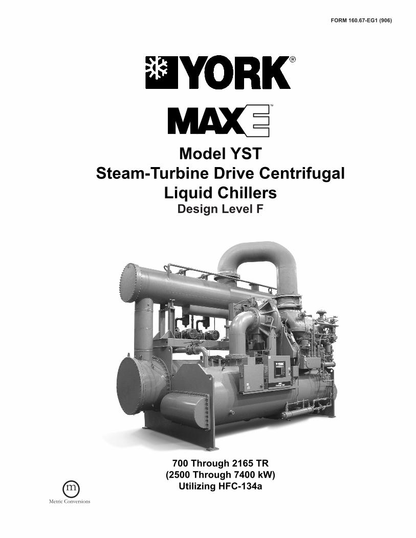
Introduction
TheYORKYSTMAXE™Chillersofferacompletecom-binationoffeaturesfortotalownersatisfaction .
MATCHED COMPONENTS MAXIMIZE EFFICIENCY
Overall chiller efficiency cannot be determined by analyz-ing the theoretical efficiency of any one chiller component. It requires a specific combination of heat exchanger, compressor, steam turbine and steam condenser perfor-mancetoachievethelowestsystemsteamrate .YORKYST MAXE chiller technology matches chiller systemcomponents to provide maximum chiller efficiency under actual-notjusttheoretical-operatingconditions .
REAL-WORLD ENERGY PERFORMANCE
YORKpioneeredtheterm“Real-WorldEnergy”toillus-trate the energy-saving potential of focusing on chillerperformanceduringoff-designconditions .Off-designisnot only part load, but full load operation as well, with re-ducedenteringrefrigerantcondenserwatertemperatures
(ECWTs). This is where chillers operate 99% of the time, andwhereoperatingcostsaddup .
The YST MAXE chillers are the only chillers designedtooperateonacontinuousbasiswithcoldECWTandfull refrigerant condenser flow at all load points, taking full advantage of Real-World conditions . This type ofoperation benefits the cooling tower as well; reducing cyclingofthefanmotorandensuringgoodcoverageofthe cooling fill.
YORKYSTMAXE chillers offer the most efficient Real-World operation of any chiller, meaning lower operating costsandanexcellentreturnonyourchillerinvestment .
OPEN DRIVE DESIGN
YORK YST MAXE centrifugal chillers utilize an opendrivecompressorthatenablestheuseofvariousdrives .Specifically, the YST uses a Steam Turbine to provide therotationalpowertodrivethechiller .Theuseofsteamas the motive energy provides owners the ability to take
4 JOHNSONCONTROLS
Introduction (continued)advantageofthemosteffectiveenergysourceavailableeitherbyusingsteamonlyorbycomplementingthiswithother“hybrid”energysourcessuchaselectricorgas .
HIGH-EFFICIENCY HEAT EXCHANGERS
YSTMAXEchillerheatexchangersofferthelatesttech-nologyinheattransfersurfacedesigntogivemaximumefficiency and compact design. Water, refrigerant and steamsidedesignenhancementsminimizebothenergyconsumptionandtubefouling .
SINGLE-STAGE COMPRESSOR DESIGN AND EFFICIENCY PROVEN IN THE MOST DEMANDING APPLICATIONS
Designed to be the most reliable chillers we’ve ever made, YORKYSTMAXEcentrifugalchillersincorporatesingle-stagecompressordesign .Withfewermovingpartsandstraightforward, efficient engineering, YORK single-stage compressors have proven durability records in hospitals, chemical plants, gas processing plants, the U.S. Navy, andinotherapplicationswhereminimaldowntimeisacrucialconcern .
In thousands of installations worldwide, YORK single-stage compressors are working to reduce energy costs. High strength, aluminum-alloy compressor impellers feature backward-curved vanes for high efficiency. Airfoil shaped, pre-rotation vanes minimize flow disruption for the most efficient part load performance. Precisely po-sitioned and tightly fitted, they allow the compressor to unloadsmoothlyfrom100%tominimumloadforexcellentoperationinairconditioningapplications .
MURRAY STEAM TURBINES - PROVEN EXPERIENCE AND HIGH EFFICIENCY
The YORK compressor, driven by a Murray Turbo-machinery multistage steam turbine provides the bestcombination of optimized efficiency and proven track record .Murraymultistageturbinesareusedtogetherwithinnovative, automated controls to integrate the turbine and compressorseamlessly .Theabilityofthesteamturbinetovaryrotationalspeedprovidesoptimalcompressoref-ficiency at all operating conditions and builds on YORK’s reputationforthebestin“Real-WorldEnergy” .Optionalautomated start and shutdown controls eliminate thetraditional manual intervention associated with steamturbinesystems .
FLEXIBILITY OF AN ITT STEAM CONDENSER PACKAGE
Unique to the YST chiller is the packaging of a steam
condensersuitableformountingonthechilleroralongsidedependingonsiterequirements .BydesigningthesteamcondenserformountingonthechillertheYSTfootprintisnolargerthanthatoftraditionalchillerssavingspaceandsimplifyingplantlayoutwhentheYSTchillerisusedincombinationwithotherYORKchillers .Thesamesteamcondenser package may be installed off the chiller, if re-quired, without modification or eliminated altogether where asteamcondensationsystemalreadyexistsonsite .
PRECISION CONTROL OF COMPRESSOR OIL PRESSURE
Utilizingourexpertiseinvariablespeeddrivetechnologyand applications, YORK has moved beyond the fixed headandbypassapproachofoilpressurecontrol .Theoldapproachonlyassuresoilpressureattheoutletofthepump rather than at the compressor, and allows no ad-justmentduringchilleroperation .TheYSTMAXEchillersfeature a variable speed drive oil pump, monitoring and providing the right amount of oil flow to the compressor onacontinuousbasis .Thisdesignalsoprovidessophisti-catedelectronicmonitoringandprotectionoftheoilpumpelectrical supply, ensuring long life and reliable operation oftheoilpumpmotor .Variablespeeddrivetechnologyreduces oil pump power consumption, running only at the speed required, rather than at full head with a pressure regulatingbypassvalve .
FACTORY PACKAGING REDUCES FIELD LABOR COSTS
YORKYSTMAXE centrifugal chillers are designed to keep installationcostslow .Whereinstallationaccessisnotaproblem, the chiller can be shipped completely packaged withsteamturbinedrivelinefactoryinstalled .Thesteamcondenser is a modular design, packaged to facilitate site installation on top of the refrigerant condenser orfloor mounted adjacent to the chiller, either arrangement requiringminimalpipingtocompletetheinstallation .Theentiresystemrequiresasinglepointpowerconnectiontominimizeonsitewiring .
TAKE ADVANTAGE OF COLDER COOLING TOWER WATER TEMPERATURES
YORKYSTMAXEcentrifugalchillershavebeendesignedto take full advantage of colder cooling tower water temperatures, which are naturally available during most operatinghours .Considerableenergysavingsareavail-able by letting tower water temperature drop, rather than artificially holding it above 75°F (24°C), especially at low load, as some chillers require.

FORM160 .67-EG1(906)
JOHNSONCONTROLS 5
RatingsCOMPUTERIZED PERFORMANCE RATINGS
Each chiller is custom-matched to meet the individualbuildingloadandenergyrequirements .Alargenumberofstandardheatexchangersandpassarrangementsareavailabletoprovidethebestpossiblematch .
Itisnotpracticaltoprovidetabulatedperformanceforeachcombination, as the energy requirements at both full and part load vary significantly with each heat exchanger and passarrangement .Computerized ratingsareavailablethrough each YORK sales office. These ratings can be tailored to specific job requirements.
OFF-DESIGN PERFORMANCE
Sincethevastmajorityofitsoperatinghoursarespentat off-design conditions, a chiller should be chosen not
only to meet the full load design, but also for its ability to perform efficiently at lower loads and lower tower water temperatures . It is not uncommon for chillers with thesame full load tohaveanoperating cost differenceofover10%duetopart-loadoperation .
Part load information can be easily and accurately gener-atedbyuseofthecomputer .Andbecauseitissoimpor-tant to an owner’s operating budget, this information has now been standardized in the form of an Integrated Part Load Value (IPLV), and Non-Standard Part Load Value (NPLV). The IPLV / NPLV formulas, in accordance with ARI Standard 550/590 guidelines, much more closely track actual chiller operations. A more detailed analysis must take into account actual building load profiles, and local weather data. Part load performance data should be obtainedforeachjobusingitsowndesigncriteria .
6 JOHNSONCONTROLS
Optiview Control CenterYST OPTIVIEW CONTROL CENTER
The YORK OptiView Control Center, furnished as stan-dard on each chiller, provides the ultimate in efficiency, automation, monitoring, data recording, chiller protection and operating ease . The Control Center is a factory-mounted, wired and tested state-of-the-art microproces-sorbasedcontrolsystemforR134acentrifugalchillers .The panel is configured with a 10.4" diagonal color Liquid Crystal Display (LCD) surrounded by “soft” keys, which are redefined with one keystroke based on the screen displayed at that time . This revolutionary developmentmakes chiller operation quicker and easier than ever before. Instead of requiring keystroke after keystroke to hunt for information on a small monochrome LCD screen, asinglebuttonrevealsawidearrayofinformationonalarge, full-color illustration of the appropriate component, which makes information easier to interpret.
TheLCDdisplayallowsgraphicanimateddisplayofthechiller, chiller sub-systems and system parameters; this allowsthepresentationofseveraloperatingparametersatonce .Thenoveluseofonscreenanimationenablesoperatorstomorereadilyidentifycomponentstatus .Inaddition, the operator may view a graphical representa-tionofthehistoricaloperationofthechilleraswellasthepresentoperation .AStatusBarisdisplayedatalltimesonallscreens .ItcontainstheSystem-StatusLineandDetails Line, the Control Source, Access Level, Time andDate .
During turbine slow roll, startup, operation and coast-down, the system status will indicate vital information availableatanytime .Thelocationsofvariouschillerpa-rameters are clearly marked and instructions for specific operationsareprovidedonmanyof thescreens .DatacanbedisplayedineitherEnglishorSIunits .
Security access is provided to prevent unauthorizedchanges of setpoints . This is accomplished with threedifferentlevelsofaccessandpasswordsforeachlevel .There are certain screens, displayed values, program-mablesetpointsandmanualcontrolsnotshownthatarefor servicing thechiller .Theyareonlydisplayedwhenloggedinatserviceaccesslevel .IncludedinthisistheAdvancedDiagnosticsand troubleshooting informationforthechillerandthepanel .
Thecontrolcenterpowersupplyisprovidedfromafused2KVAtransformerlocatedinthepowerpanel .
Thecontrolcenterisalsofusedtoprovideindividualover-currentprotectedpower for the remotemountedwaterpumpmotorstarters(suppliedbyothers)andthecontrols
installedonthechiller .Numberedterminalstripsforwir-ing such as Remote Start / Stop, Chilled Water Pump andLocalorRemoteCyclingdevicesareprovided .ThePanel also provides field interlocks that indicate the chiller status .ThesecontactsincludeaRemoteModeReady-to-Start, a Controlled Shutdown, a Safety Shutdown and achillerRuncontact .Systempressuresaremonitoredwithtransmitters(4-20mA)andtransducers(0-5VDC) .System temperatures are monitored using thermistorsandRTD’s .
Setpointscanbechangedfromaremotelocationvia0-10VDC and 4-20mA, contact closures or through serial communications .Theadjustableremoteresetrange[upto 20°F (11.1°C)] provides flexible, efficient use of remote signaldependingonresetneeds .Serialdata interfaceto the YORK ISN Building Automation System (BAS)is through the optional Microgateway Card, which can bemountedinsidetheControlCenter .Interfacesusingother industry standard protocols such as MODBUS RTU, Johnson NZ, BACnet MS/TP, LONMARK and ASCII are available .
The operating program is stored in non-volatile mem-ory to eliminate chiller failure due to AC power failure/battery discharge. Programmed setpoints are retained in lithium battery-backed RTC memory for 11 years minimum .
Smart Freeze Point Protection will run the chiller at 36°F (2.2°C) leaving chilled water temperature eliminating nuisancetripsonLowWaterTemperature .Thesophisti-catedprogramandsensorswillmonitorthechillerwaterandevaporatorrefrigerantliquidtemperaturestopreventfreezeup .Everyprogrammablepointhasapop-upscreenwith the allowable ranges, so that the chiller can not be programmedtooperateoutsideofitsdesignlimits .
Thecapacitycontrol logicprovidesstableoperationatmaximum efficiency at off design conditions by modulat-ing the turbine speed, compressor pre-rotation vanes and hotgasby-passvalve .
When the power is applied to the chiller, the HOME screen isdisplayed .Thisscreendisplaysavisualrepresentationofthechillerandacollectionofdatadetailingimportantoperations and parameters . The primary values thatneedtobemonitoredandcontrolledareshownonthisscreen. The owner can be confident that YORK’s OptiView control system for the YST is unequalled in its design, control features and protection systems . See “Equip-ment Specifications” for a more detailed description of OptiViewfeatures .

FORM160 .67-EG1(906)
JOHNSONCONTROLS 7
Equipment SpecificationsGENERAL
The YORK YST MaxE Centrifugal Liquid Chillers arecompletely factory-packaged including the evaporator, refrigerant condenser, compressor, steam turbine, lubri-cation systems, power panel, control center, and all inter-connectingunitpipingandwiring .Thesteamcondenserpackage is shipped separately suitable for direct mounting ontothechillerormountingalong-side .
Theinitialchargeofrefrigerantandoilissuppliedforeachchiller .Whentheoptionalrefrigerantcondenserisolationvalves are ordered, the unit may ship fully charged with refrigerantandoil .Actualshippingprocedureswilldependon a number of project-specific details.
The services of a YORK factory-trained, field service rep-resentative are incurred to supervise or perform the final leak testing, charging, the initial start-up, and concurrent operatorinstructions .
COMPRESSOR
Thecompressorisasingle-stagecentrifugaltypepow-eredbyasteamturbine .Thecasingisfullyaccessiblewithverticalcircularjointsandfabricatedofclose-graincastiron .Thecompleteoperatingassemblyisremovablefromthecompressorandscrollhousing .Therotorassemblyconsistsofaheat-treatedalloysteeldrive shaft and impeller shaft with a high strength, cast aluminum alloy, fully shrouded impeller. The impeller is designed for balanced thrust and is dynamically bal-anced and overspeed tested for smooth, vibration free operation .
Theinsert-typejournalandthrustbearingsarefabricatedof aluminum alloy and are precision bored and axiallygrooved. The specially engineered, single helical gears withcrownedteetharedesignedsothatmorethanonetoothisincontactatalltimestoprovideevendistributionofcompressorloadandquietoperation .Gearsareintegrallyassembled in the compressor rotor support and are film lubricated .Eachgearisindividuallymountedinitsownjournalandthrustbearingstoisolateitfromimpellerandturbineforces .
CAPACITY CONTROL
During part load operation at off design conditions, the chillercapacityisreducedtomaintainaconstantleavingchilled liquid temperature by first decreasing the speed, then closing the compressor pre-rotation vanes (PRV). This provides capacity reduction from 100% to 15%of design for normal air conditioning applications .The
speediscontrolledbyapneumaticallyactuatedgovernorvalve which throttles the inlet steam flow to the turbine to maintainthespeeddictatedbythecapacitycontrollogic .If the tower water temperatures must be held above 75°F for other chillers, the capacity control logic automatically limits the amount of speed reduction and PRV closure tomaintainstableoperation .Thehotgasby-passvalveisthenmodulatedtomaintainaconstantleavingchilledliquidtemperaturewithloadsdownto10%ofdesign .
The vanes are actuated by an external, electric PRV ac-tuator. Rugged, airfoil shaped, cast manganese bronze vanes are precisely positioned by solid vane linkages connectedtotheelectricactuator .
COMPRESSOR LUBRICATION SYSTEM
Lubrication oil is force-fed to all bearings, gears and rotatingsurfacesbyavariablespeeddrivepumpwhichoperates prior to startup, continuously during operation andduringcoastdown .Agravity-fedoilreservoirisbuiltintothetopofthecompressortoprovidelubricationduringcoastdownintheeventofapowerfailure .
An oil reservoir, separate from the compressor, contains the submersible oil pump, 2 HP pump motor and 3000 watt immersion-typeoilheater .Theoilheateristhermostati-callycontrolledtoremoverefrigerantfromtheoil .
Oil is filtered by an externally mounted 1/2 micron replace-able cartridge oil filter equipped with service valves. Oil is cooled via a shell and tube, water cooled oil cooler sizedtouserefrigerantcondenserwaterasthecoolingmedium .Theoilsideoftheoilcoolerisprovidedwithser-vicevalves .Oilpipingiscompletelyfactory-installed .Thewater side of the oil cooler is provided with service valves, inlet strainer and solenoid valve for automatic start/stop of cooling water flow. Water piping is factory installed with customerconnectionsconvenientlybroughttotheedgeof the chiller package and clearly tagged for installation. Anautomaticoilreturnsystemrecoversanyoilthatmayhavemigratedtotheevaporator .Oiltemperaturecontrolis by an Amot, three way temperature control valve.
STEAM TURBINE
The steam turbine is a high efficiency multistage de-signoperatingatanominal4500rpmdesignmaximumspeed .
The turbine is packaged on a driveline base, completely factory piped. The driveline base has a mating flange on shaft end of the package that will bolt directly to the compressor D-flange face providing a rigid interface between turbine package and compressor. Complete

� JOHNSONCONTROLS
Equipment Specifications (continued)turbine/compressor driveline is factory aligned prior to shipment .Turbinedriveshaftisdirectlyconnectedtothecompressor shaft with a flexible disc coupling. Coupling isofanallmetalconstructionwithnowearingpartsas-suringlonglifeandnolubricationrequirementsprovidinglowmaintenance .
Theturbinecasingishorizontallysplitdesignedtoallowlongitudinalthermalexpansionwithouttheaffectingalign-ment or efficiency of the turbine. The shaft and wheels are alloy steel with the wheels shrunk and keyed to the shaft. Theturbinebladesare403gradestainlesssteelandtheshaftisgroundthroughoutwithstainlesssteelsprayedinthecarbonringendglandcontactarea .Stainlesssteelnozzlesarefurnishedthroughouttheturbine .Carbonringendglandanddiaphragmsealsare furnished .Turbineend gland carbon ring seals (minimum five seals per end gland)areseparatedbypartitionsofstainlesssteel .
A stainless steel, inlet steam strainer with adequate size and mesh to minimize the pressure drop is supplied .Strainer is removable without breaking the steam piping connections .
Blanket insulation is furnished on the steam chest and barreloftheturbineforoperatorprotection .
The turbine speed is controlled by a governor valvewhichisintegratedwiththechillercontrols .Thevalveisofstainlesssteelwithstainlesssteelseatsanddesignedto control flow throughout the entire operating range of theturbine .Thesystememploysanoverspeedgovernordesigned to close an independent high performancebutterfly trip valve with a pneumatic actuator when the turbine speed exceeds 110 percent of the maximumcontinuousoperatingspeedoftheturbine .Activationoftheindependenttripvalvecausesthegovernorvalvetoalso close. A micro switch is furnished on the trip linkage forthecustomer’suse .
TURBINE LUBRICATION SYSTEMS
RingOil LubricatedTurbines -Drivepowers less than1700Hp (1268 kW) onlyThe bearings are steel backed, babbitt lined, split sleeve type .Thedesignissuchthatthebottomhalfisremov-able with the shaft in place . The bearing housing hasprovisionsforairpurgingofthehousingshaftseals .Thethrust bearing is an antifriction ball bearing, accessible andremovablewithoutliftingthetophalfoftheturbinecasing .Oilcoolingisbywatercooledbearinghousings .
External, Pressurized Lube System TurbinesThe bearings are steel backed, babbitt lined, split sleeve type .Thedesignissuchthatthebottomhalfisremov-
able with the shaft in place . The bearing housing hasprovisionsforairpurgingofthehousingshaftseals .Thethrust bearing is a double acting, Kingsbury type. The lubricationsystemisintegraltotheturbinedrivelinebaseand completely factory piped . The lubrication systemconsists of a shaft driven main oil pump, motor driven auxiliary oil pump, water cooled shell and tube oil cooler, 25 micron full flow oil filter and separate oil reservoir with level gauge. Oil temperature control is by an Amot, three waytemperaturecontrolvalve .
STEAM CONDENSER PACKAGE
A steam condenser is provided to condense exhauststeam at vacuum pressures to maintain efficient turbine operation .Thesteamcondenserwater circuit ispipedin series with the refrigerant condenser, eliminating a separatecoolingwatercircuitandisdesignedtominimizepressuredropforenergysavings .
The steam condenser is furnished fully packaged. The package includes a single hotwell pump, a single liquid ring vacuum pump for air removal, atmospheric relief valve and level control system. The package is factory piped, wired andmountedonacommonstructuralsteelframesuitablefor installation on the refrigerant condenser or floor mount-ingadjacenttothechillersystem .
Condensateleveliscontrolledbyalevelcontrolsystemwithtwo(2)pneumaticcontrolvalves-oneforre-circula-tionandtheotherforremovalofcondensate .Theliquidringvacuumpumpiscapableofdrawingthecondenserdowntooperatingpressureinapproximately10minutes .Hotwell pump is single-stage, end suction suitable for hotwellservice .Steamsideisdesignedfor15psig(100kPa) and 30" Hg Vac (760 mmHg).
Atmosphericreliefvalveisawatersealtypewithexternalhandwheel, sized in accordance with the Heat Exchange InstituteStandards(HEI)forprotectionofthesteamtur-bine exhaust, steam trunk and steam condenser.
All key control and monitoring parameters are integrated with the chiller control panel. In addition, auxiliary pres-suregaugesare locatedat the condenser steam inletand condensate pump discharge piping, and temperature gauges are located at the steam inlet, cooling water inlet and outlet, and the hotwell.
To facilitate rigging, condenser is separable from the skid by unbolting. Piping is outfitted with unions at suitable break-points. Both condenser and skid are outfitted with liftinglugsforbothverticalandhorizontallifting .
FORM160 .67-EG1(906)
JOHNSONCONTROLS 9
HEAT EXCHANGERSShells
Evaporator, refrigerant condenser and steam condenser shellsarefabricatedfromrolledcarbonsteelplateswithfusion welded seams. Carbon steel tube sheets, drilled and reamed to accommodate the tubes, are welded to the end of each shell . Intermediate tube supports arefabricated from carbon steel plates, drilled and reamed to eliminatesharpedges .Therefrigerantsideofeachshellisdesigned, tested, and stamped in accordance with ASME Boiler and Pressure Vessel Code, Section VIII - Division I, orotherpressurevesselcodeasappropriate .Thesteamsideofthesteamcondenserisdesignedinaccordancewith the Heat Exchange Institute (HEI), an industry stan-dardforsteamcondensertechnology .
Tubes
Refrigerant heat exchanger tubes are state-of-the-art, high-efficiency, externally and internally enhanced type to provideoptimumperformance .Tubesinboththeevapo-rator and refrigerant condenser are 3/4" O.D. (19 mm) copper alloy and utilize the “skip-fin” design, providing a smoothinternalandexternalsurfaceateachintermedi-ate tube support. This provides extra wall thickness (up to twice as thick) and non-work hardened copper at the support location, extending the life of the heat exchangers. Eachtubeisrollerexpandedintothetubesheetsprovidinga leak-proof seal, and is individually replaceable. Steam condenser tubes are copper, providing economical and efficient heat transfer.
Evaporator
The evaporator is a shell and tube, flooded type heat ex-changer .Adistributortroughprovidesuniformdistributionofrefrigerantovertheentireshelllengthtoyieldoptimumheat transfer. A suction baffle or aluminum mesh elimina-torsarelocatedabovethetubebundletopreventliquidrefrigerant carryover into the compressor. A 1-1/2" (38 mm)liquidlevelsightglassisconvenientlylocatedonthesideoftheshelltoaidindeterminingproperrefrigerantcharge .Theevaporatorshellcontainsadualrefrigerantrelief valve arrangement set at 180 psig (1241 kPa); or single-relief valve arrangement, if the chiller is supplied with the optional refrigerant isolation valves. A 3/4" (19 mm) flare male charging connection is provided.
Refrigerant Condenser
The refrigerant condenser is a shell and tube type, with a discharge gas baffle to prevent direct high velocity impinge-ment on the tubes. The baffle is also used to distribute the refrigerant gas flow properly for most efficient heat transfer. Anintegralsub-coolerislocatedatthebottomoftherefriger-antcondensershellprovidinghighlyeffectiveliquidrefriger-ant subcooling to provide the highest cycle efficiency. The refrigerantcondensercontainsdualrefrigerantreliefvalves
set at 235 psig (1620 kPa).
Steam Condenser
Steamcondenserconstructionisoftheshellandtubetypeof welded steel construction with 3/4" OD (19 mm) prime surface copper tubes, roller-expanded into tube sheets. Animpingementplatelocatedbelowthecentrallylocatedsteam inlet redirects steam flow to protect the tubes from highvelocitysteam .Subcoolingsectionsinthecondensercool non-condensibles sufficiently below the condensing temperaturetherebyreducingthevacuumpumpcapacityrequired. Water side is suitable for a maximum working pressure of 150 psig (1030 kPa). An atmospheric relief valve, sized per HEI to protect the condenser, is included. This relief valve is set to open at 1-2 psig (7-14 kPa) and willpreventpressureinthecondensershellfromexceed-ing 10 psig (69 kPa). Seal water is required to maintain a liquid seal in the valve. An inlet and overflow connection isprovidedonthevalveforthispurpose .
Water Boxes
Thewaterboxesarefabricatedfromsteelandaremarinestyle(compactormarineavailableonevaporator) .Thestandard design working pressure is 150 psig (1030 kPa) and the chiller boxes are tested at 225 psig (1550 kPa). Steam condenser boxes are tested at 215 psig (1480kPa). Integral steel water baffles are located and welded within thewaterboxtoprovidetherequiredpassarrangements .Stub-outwaternozzleconnectionswithVictaulicgroovesareweldedtothewaterboxes .Thesenozzleconnectionsare suitable for Victaulic couplings, welding or flanges, and are capped for shipment. Plugged 3/4" NPTI (19 mm) drain andventconnectionsareprovidedineachwaterbox .
REFRIGERANT FLOW CONTROL
Refrigerant flow to the evaporator is controlled by the YORK variable orifice control system. Liquid refrigerant level is continuously monitored to provide optimum subcooler, refrigerantcondenserandevaporatorperformance .Thevariable orifice electronically adjusts to all Real-World op-erating conditions, providing the most efficient and reliable operation of refrigerant flow control.
POWER PANEL
All motor contactors and circuit protectors, the compressor oilpumpvariablespeeddriveandthecontrolpowertrans-formerarecontainedinanenclosureinstalledadjacenttotheOptiViewcontrolcenter .Amainpowerdisconnectswitchissuppliedwhichprovidestheterminationpointsforcustomer’ssinglepointpowersupplywiring .
10 JOHNSONCONTROLS
Equipment Specifications (continued)OPTIVIEW CONTROL CENTERGeneral
Thechilleriscontrolledbyastand-alonemicroprocessorbasedcontrolcenter .Thechillercontrolpanelprovidescontrol of entire system, including turbine and steam condenseroperationandmonitoring .
The control panel includes a 10.4". diagonal color liquid crystal display (LCD) surrounded by “soft” keys which are redefined based on the screen displayed at that time, mounted in the middle of a keypad interface and installed in a locked enclosure. The screen details all operations and parameters, using a graphical representation of the chiller and its major components. Panel text is in English only .Datacanbedisplayed ineitherEnglishorMetricunits .Additionalfeaturesare:• Smart Freeze Point Protection capable of running
the chiller at 36°F (2.2°C) leaving chilled water temperatureeliminatingnuisancetripsonlowwatertemperature .Thesophisticatedprogramandsensorsmonitorthechillerwaterandevaporatorrefrigerantliquidtemperaturestopreventfreeze-up .
• Thepaneldisplayscountdowntimermessagessotheoperator knows when functions are starting and stop-ping .Everyprogrammablepointhasapop-upscreenwith the allowable ranges, so that the chiller can not be programmedtooperateoutsideofitsdesignlimits .
• Security access is built in to prevent unauthorizedchange of setpoints, to allow local or remote control of the chiller, and to allow manual operation of the pre-rotationvanesandoilpump .AccessisthroughIDand password recognition, which is defined by three different levels of user competence: view, operator, andservice .
• Trendingdataisavailablewiththeabilitytocustomizepointsfromonceeverysecondtoonceeveryhour .Thepanelwilltrendupto6differentparametersfroma list of over 140, without the need of an external monitoringsystem .
• The operating program is stored in non-volatilememorytoeliminatereprogrammingthechillerduetoAC power failure or battery discharge. Programmed setpoints are retained in lithium battery-backed RTC memory foraminimumof11yearswithpower re-movedfromthesystem .
• IncludesanRS-232porttooutputallsystemoperatingdata, shutdown/cycling message, and a record of the last 10 cycling or safety shutdowns to a field-supplied printer .Datalogstoaprinteratasetprogrammableinterval .Thisdatacanbeprepro-grammedtoprintfrom1minuteto1day .
• Thetextdisplayedwithinthesystemstatusandsys-tem details field is displayed as a color-coded mes-sage to indicate severity: red for safety fault, orange
for cycling faults, yellow for warnings, and green for normalmessages .
Thechillercontrolpanelprovidesamultitudeofdiagnosticandoperatingdatatoonumeroustocovercompletelyinthis guide. However, a general description of some of thedataavailableandexamplesofthevariousscreensprovidedfollows:
Somehighlights(notallinclusive)ofthedataavailableonthepanelareasfollows:SYSTEM OPERATING INFORMATIONEvaporator
• Leavingandreturnchilledwatertemperature• Refrigerantliquidtemperature-evaporator• Evaporatorpressure• Hotgascontrolstatus• Chilled water flow
Refrigerant Condenser
• Entering and leaving refrigerant condenser watertemperature
• Refrigerantliquidtemperature-refrigerantcondens-er
• Refrigerantcondenserpressure• Subcoolerrefrigerantliquidlevel• Subcoolerrefrigerantliquidlevelcontrolstatus• Refrigerant condenser water flow
Compressor
• Compressordischargetemperature• Compressoroiltemperature• Compressorsupplyoilpressure• Compressor thrust bearing proximity probe gap (J
compressorsonly)• Pre-rotation vanes (PRV) position
Steam Turbine
• Turbineshaftendbearingtemperature• Turbinegovernorendbearingtemperature• Turbineinletsteamtemperature• Turbineinletsteampressure• Turbine first stage steam pressure• Turbineexhaustpressure• Turbinespeed• Turbinegovernorcontrolstatus
Steam Condenser
• Hotwellcondensatelevel• Hotwelllevelcontrolstatus
SAFETY SHUTDOWNS (will prevent unit from starting or operating)

FORM160 .67-EG1(906)
JOHNSONCONTROLS 11
• Evaporator-lowpressure• Evaporator - low temperature (Smart Freeze Point
Protection)• Evaporator-transducerorleavingliquidprobefail-
ure• Evaporator-transducerortemperaturesensorfail-
ure• Refrigerant condenser - high pressure contacts
open• Refrigerantcondenser-highpressure• Refrigerantcondenser-pressuretransducerout-of-
range• Compressordischarge-hightemperature• Compressordischarge-lowtemperature• Compressoroil-hightemperature• Compressoroil-lowdifferentialtemperature• Compressoroil-highdifferentialpressure• Compressoroil -sumppressuretransducerout-of-
range• Compressoroil-differentialpressurecalibration• Compressor oil - variable speed pump - pressure
setpointnotachieved• Compressorthrustbearing-proximityprobeuncali-
brated(Jcompressorsonly)• Compressor thrustbearing-proximityprobeclear-
ance(Jcompressorsonly)• Compressorthrustbearing-proximityprobeout-of-
range(Jcompressorsonly)• Controlpanel-powerfailure• Turbinegovernorendbearinghightemperature• Turbineshaftendbearinghightemperature• Turbineoil-lowpressure• Turbineoil-hightemperature• Turbineunderspeed• Turbineexhausthighpressure• Standby hotwell pump fault (warning on failure of
primarypump)• Standby vacuum pump - no sealing water flow (warn-
ingonfailureofprimarysystem)• Standbyvacuumpump fault (warningon failureof
primarypump)• Hotwellcondensatehighlevel• Hotwellcondensatelowlevel
CODES AND STANDARDS
• ASME Boiler and Pressure Vessel Code - Section Vlll Division1 .
• Heat Exchange Institute (HEI), Industry Standard for SteamCondensers
• NEMA(SM23)SteamTurbinesforMechanicalDriveServices
• Expansion Joint Manufacturers Assoc., Inc. (EJMA)• ARI Standard 550/590• ASHRAE15-SafetyCodeforMechanicalRefrigera-
tion• ASHRAEGuideline3-ReducingEmissionofHaloge-
natedRefrigerantsinRefrigerationandAir-Condition-ingEquipmentandSystems
• N .E .C .-NationalElectricalCode• OSHA-OccupationalSafetyandHealthAct
ISOLATION MOUNTING
Theunitisprovidedwithfourvibrationisolationmountsconsisting of 1" (25.4 mm) thick neoprene isolation pads for field mounting under the steel mounting plates located onthetubesheets .
REFRIGERANT CONTAINMENT
Therefrigerantcircuithasbeendesignedasa factory-packaged system. As such, it has minimum joints from which refrigerant can leak. The entire assembly has been thoroughly leak tested at the factory prior to shipment. TheYORKchiller includesservicevalvesconvenientlylocated to facilitate transfer of refrigerant to a remoterefrigerant storage/recycling system. Optional refrigerant condenserisolationvalvesallowstorageofthechargeintherefrigerantcondenser .
PAINT
ExteriorsurfacesareprotectedwithonecoatofCaribbeanblue, durable alkyd-modified, vinyl enamel, machinery paint .
SHIPMENT
Protective covering is furnished on the control center. Water nozzles are capped with fitted plastic enclosures. Entire unit is protected with industrial-grade, reinforced shrink-wrapped covering.

12 JOHNSONCONTROLS
Accessories and ModificationsFLOOR MOUNTED STEAM CONDENSERAs an alternative to the standard packaged location, the steam condenser package can be ordered for floor mounting adjacent to the chiller package. Prefabricated piping kits for the steam trunk, water piping and wiring between chiller package and steam condenser are not included with a floor mounted arrangement. These in-terconnecting components must be designed, supplied andinstalledbycustomer .
Note: Interconnecting components may be orderedthrough the factoryviaaspecialquoteuponrequest(site arrangement details will be required at time ofrequestforquote) .
AUTO-START CONTROL FEATURES
When this option is ordered, the chiller is provided with all components and programming for the OptiViewmicropanel to automatically control the start-up andshutdownofthesystem .Allsolenoidsandautomatedcomponentsnecessaryforfullautomationareprovided .Somepartswill ship loose for installationat jobsite .Anautomaticpressurepoweredpumpisalsoprovidedfordrainingcondensatefromthesteamturbinecasingduringoperation .
DUAL PUMPS FOR STEAM CONDENSER PACKAGE
Factory installed secondary (100% standby duty)condensate and vacuum pumps, including all intercon-nectingpipingisavailable .Automaticswitchovertoastandbypumpintheeventofaprimarypumpfailureisincludedinthisoption .
STEAM TURBINE CASING DRAIN OPTIONS
Thesteamturbinecasingmustbeprovidedwithameansofdrainingduringoperation(whileundervacuum) .Fac-toryoptionsavailableforthisfunctionare:
•Automaticpressurepoweredpump• Manual condensate drain tank (by special quote) • Automatic condensate drain tank (by special quote)
Casingdrainequipmentisshippedlooseforinstallationatjobsite .
FACTORY INSULATION
Factory-applied thermal insulation of the flexible, closed-cell plastic type, 3/4" (19 mm) thick is attached with va-por-proof cement to the evaporator shell, flow chamber, tube sheets, suction connection, and (as necessary) to theauxiliary tubing . Not included is the insulationofcompactwaterboxesandnozzles .Thisinsulationwill
normally prevent condensation in environments withrelativehumiditiesupto75%anddrybulbtemperaturesranging from 50° to 90°F (10° to 32°C). 1-1/2" (38 mm) thick insulation is also available for relative humidities up to 90% and dry bulb temperatures ranging from 50° to 90°F (10° to 32°C).The turbine steam chest is insulated with a customfitted, fiberglass insulating blanket for protection of personnel .
WATER FLANGES
150 psig (1030 kPa) ANSI raised-face flanges for refrigerant condenser, evaporator and steam condenser water con-nections, are factory-welded to water nozzles. Companion flanges, bolts, nuts and gaskets are not included.
MARINE WATER BOXES
Marinewaterboxesallowserviceaccessforcleaningofthe heat exchanger tubes without the need to break the waterpiping .Bolted-oncoversarearrangedforconve-nient access. Victaulic nozzle connections are standard; flanges are optional. Marine water boxes are available fortheevaporator(limitedarrangementsonly) .
NOTE: Marine water boxes are standard scope of supply on the refrigerant and steam condensers.
KNOCK-DOWN SHIPMENTThe chiller can be shipped knocked down into major subassemblies (evaporator, refrigerant condenser, driveline, etc.) as required to rig into tight spaces. This isparticularlyconvenient forexistingbuildingswhereequipmentroomaccessdoesnotallowriggingafac-tory-packaged chiller.
NOTE: Vertical rigging if components not allowed unless special design is ordered by special quote (SQ).
REFRIGERANT ISOLATION VALVES
Optional factory-installed isolationvalves inthecom-pressor discharge line and refrigerant liquid line areavailable . This allows isolation and storage of therefrigerantcharge in thechiller refrigerantcondenserduring servicing, eliminating time-consuming transfers toremotestoragevessels .Bothvalvesarepositiveshut-off, assuring integrity of the storage system.
300 PSIG WATERSIDE DESIGN PRESSURE
Applications with greater than 150 psig (1030 kPa) water pressurecanbeaccommodatedbyspecialquoteuponrequest .Specialdesignrequiredforallheatexchanger
FORM160 .67-EG1(906)
JOHNSONCONTROLS 13
water boxes and turbine/compressor cooling water circuits .
BAS NETWORK INTERFACE
A communication interface permitting complete ex-changeofchillerdatawithanyBASSystemisavailablewithoptionalISNMicroGateway .TheMicro-GatewayalsoallowsaBASSystemtoissuecommandstothechillertocontrol itsoperation .Allcontroldatapointsare accessible to the BAS System. For full list of points, contact a York Controls Representative.
REFRIGERANT STORAGE / RECYCLING SYSTEM
A refrigerant storage/recycling system is a self-con-tained package consisting of a refrigerant compressor with oil separator, storage receiver, water-cooled con-denser, filter drier and necessary valves and hoses to remove, replace and distill refrigerant. All necessary controlsandsafetydevicesareapermanentpartofthesystem . Typicallynot required ifunit isolationvalvesareprovided .
14 JOHNSONCONTROLS
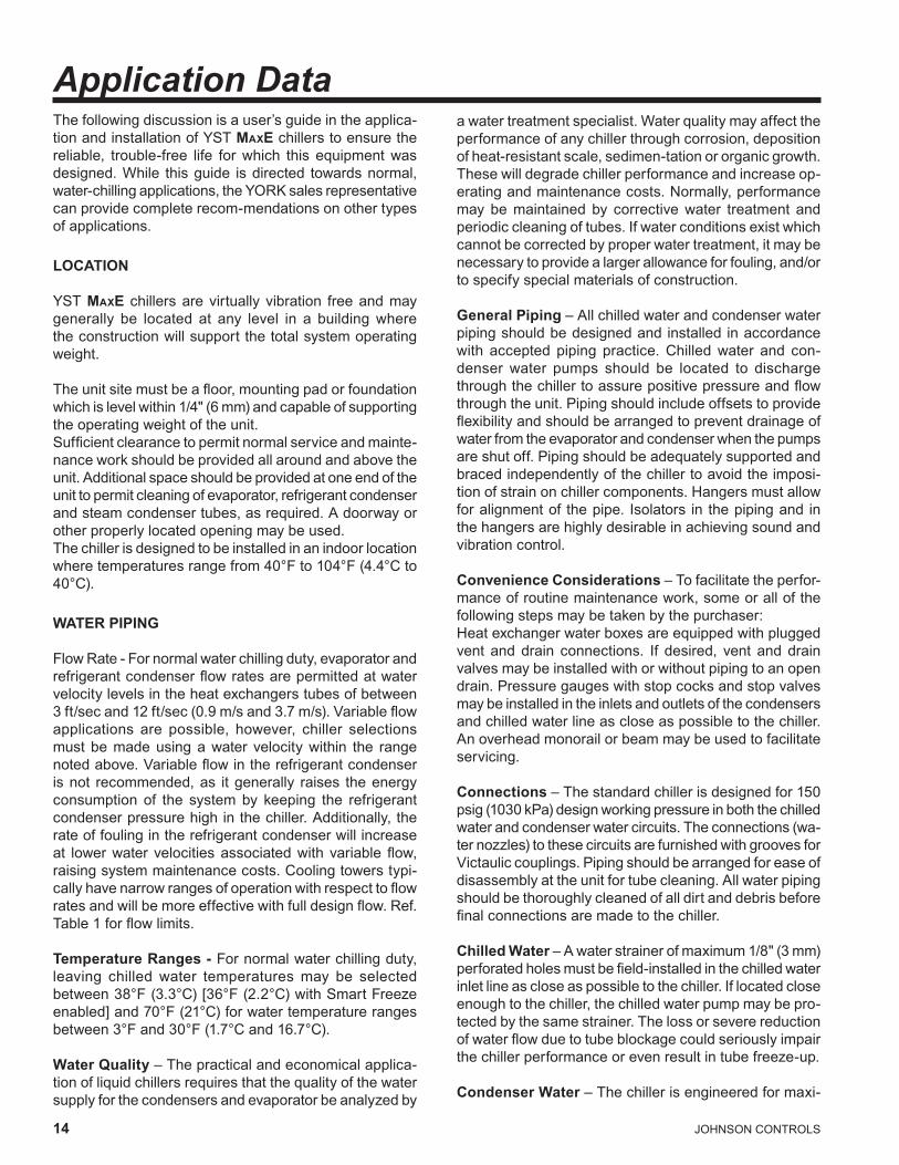
Application DataThefollowingdiscussionisauser’sguideintheapplica-tionandinstallationofYSTMaxEchillerstoensurethereliable, trouble-free life for which this equipment was designed. While this guide is directed towards normal, water-chilling applications, the YORK sales representative canprovidecompleterecom-mendationsonothertypesofapplications .
LOCATION
YSTMaxE chillersarevirtuallyvibration freeandmaygenerally be located at any level in a building wheretheconstructionwillsupportthetotalsystemoperatingweight .
The unit site must be a floor, mounting pad or foundation which is level within 1/4" (6 mm) and capable of supporting theoperatingweightoftheunit .Sufficient clearance to permit normal service and mainte-nance work should be provided all around and above the unit .Additionalspaceshouldbeprovidedatoneendoftheunit to permit cleaning of evaporator, refrigerant condenser and steam condenser tubes, as required. A doorway or otherproperlylocatedopeningmaybeused .Thechillerisdesignedtobeinstalledinanindoorlocationwhere temperatures range from 40°F to 104°F (4.4°C to 40°C).
WATER PIPING
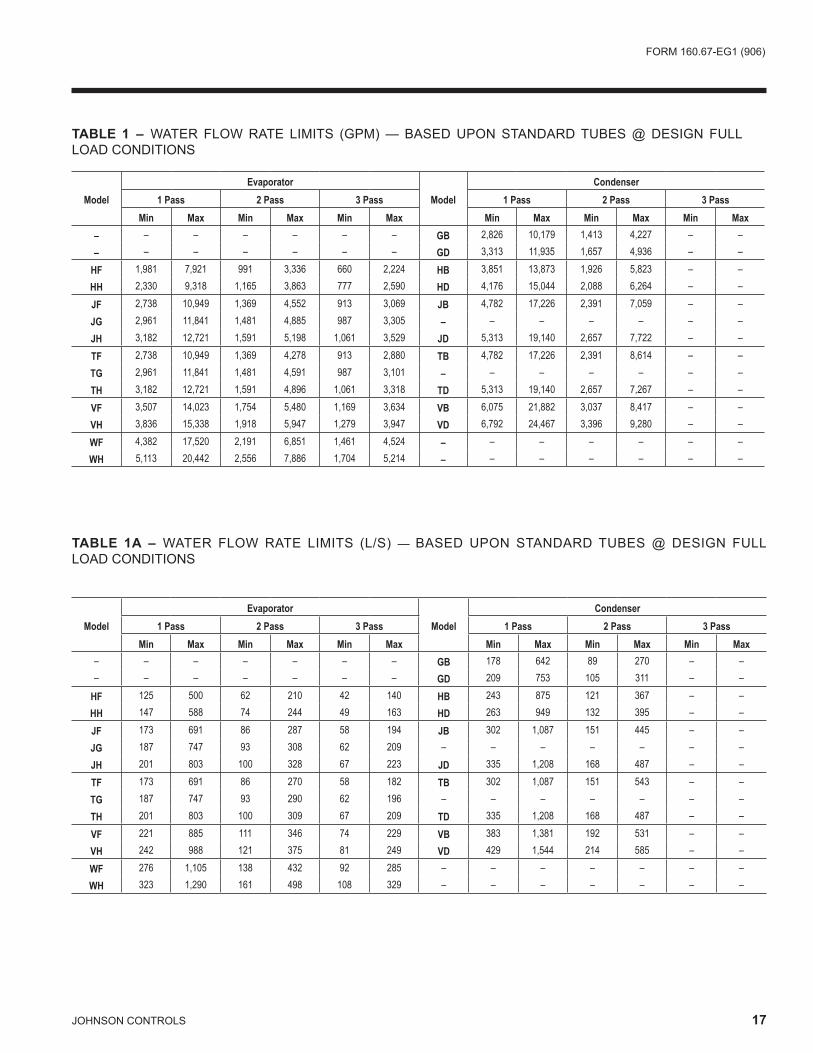
Flow Rate - For normal water chilling duty, evaporator and refrigerant condenser flow rates are permitted at water velocitylevelsintheheatexchangerstubesofbetween3 ft/sec and 12 ft/sec (0.9 m/s and 3.7 m/s). Variable flow applications are possible, however, chiller selections mustbemadeusingawater velocitywithin the rangenoted above. Variable flow in the refrigerant condenser is not recommended, as it generally raises the energy consumption of the system by keeping the refrigerant condenser pressure high in the chiller. Additionally, the rateoffoulingintherefrigerantcondenserwillincreaseat lower water velocities associated with variable flow, raisingsystemmaintenancecosts .Coolingtowerstypi-cally have narrow ranges of operation with respect to flow rates and will be more effective with full design flow. Ref. Table 1 for flow limits.
Temperature Ranges - For normal water chilling duty, leaving chilled water temperatures may be selectedbetween 38°F (3.3°C) [36°F (2.2°C) with Smart Freeze enabled] and 70°F (21°C) for water temperature ranges between 3°F and 30°F (1.7°C and 16.7°C).
Water Quality–Thepracticalandeconomicalapplica-tionofliquidchillersrequiresthatthequalityofthewatersupplyforthecondensersandevaporatorbeanalyzedby
awatertreatmentspecialist .Waterqualitymayaffecttheperformance of any chiller through corrosion, deposition of heat-resistant scale, sedimen-tation or organic growth. Thesewilldegradechillerperformanceandincreaseop-erating and maintenance costs. Normally, performance may be maintained by corrective water treatment andperiodiccleaningoftubes .Ifwaterconditionsexistwhichcannot be corrected by proper water treatment, it may be necessary to provide a larger allowance for fouling, and/or tospecifyspecialmaterialsofconstruction .
General Piping–Allchilledwaterandcondenserwaterpipingshouldbedesignedandinstalled inaccordancewith accepted piping practice . Chilled water and con-denser water pumps should be located to dischargethrough the chiller to assure positive pressure and flow through the unit. Piping should include offsets to provide flexibility and should be arranged to prevent drainage of waterfromtheevaporatorandcondenserwhenthepumpsare shut off. Piping should be adequately supported and bracedindependentlyofthechillertoavoidtheimposi-tionofstrainonchillercomponents .Hangersmustallowforalignmentof thepipe . Isolators in thepipingand inthehangersarehighlydesirableinachievingsoundandvibrationcontrol .
Convenience Considerations–Tofacilitatetheperfor-mance of routine maintenance work, some or all of the following steps may be taken by the purchaser: Heatexchangerwaterboxesareequippedwithpluggedvent and drain connections. If desired, vent and drain valvesmaybeinstalledwithorwithoutpipingtoanopendrain. Pressure gauges with stop cocks and stop valves maybeinstalledintheinletsandoutletsofthecondensersandchilledwaterlineascloseaspossibletothechiller .Anoverheadmonorailorbeammaybeusedtofacilitateservicing .
Connections–Thestandardchillerisdesignedfor150psig (1030 kPa) design working pressure in both the chilled waterandcondenserwatercircuits .Theconnections(wa-ternozzles)tothesecircuitsarefurnishedwithgroovesforVictaulic couplings. Piping should be arranged for ease of disassemblyattheunitfortubecleaning .Allwaterpipingshouldbethoroughlycleanedofalldirtanddebrisbeforefinal connections are made to the chiller.
Chilled Water – A water strainer of maximum 1/8" (3 mm) perforated holes must be field-installed in the chilled water inletlineascloseaspossibletothechiller .Iflocatedcloseenough to the chiller, the chilled water pump may be pro-tectedbythesamestrainer .Thelossorseverereductionof water flow due to tube blockage could seriously impair thechillerperformanceorevenresultintubefreeze-up .
Condenser Water–Thechillerisengineeredformaxi-

FORM160 .67-EG1(906)
JOHNSONCONTROLS 15
mum efficiency at both design and part load operation by taking advantage of the colder cooling tower water temperatures which naturally occur during the wintermonths . Appreciable power savings are realized fromthesereducedheads .Theminimumenteringcondenserwatertemperatureisprovidedbythefollowingequation:
In °F: minCondWT = LChilledWT - CondRange x (PCT-Load/100) + 5 + 12 x (PctLoad/100)In °C: minCondWT = LChilledWT - CondRange x (PCT-Load/ 100) + (5 + 12 x (PctLoad/100))/1.8
where:
minCondWT = entering condenser water temperatureLChilledWT = leaving chilled water temperatureCondRange = condenser water temperature range at design .PCTLoad = chiller load as % design
At initial startup, entering condensing water temperature may be as much as 25°F (14°C) colder than the standby chilledwatertemperatureaslongasitisabovethemini-mumenteringcondenserwatertemperatureallowed .A water strainer of maximum 1/8" (3 mm) perforated holes is recommended to be field-installed in the refrigerant con-denserwaterinletlineascloseaspossibletothechiller .If located close enough to the chiller, the condenser water pumpmaybeprotectedbythesamestrainer .Thelossorsevere reduction of water flow due to tube blockage could seriouslyimpairthechillerperformance .
STEAM AND CONDENSATE PIPING
Turbinesupplysteamandcondensatepipingconnectionstothechilleraretobesuppliedandinstalledbythesitepiping contractor. In addition, the turbine exhaust to the steamcondensershallbeinstalledbythepipingcontrac-tor, however, the design and supply of components may besuppliedbyYORKdependingontheoptionschosen .Piping should be adequately supported and braced inde-pendentlyofthechillers .Hangersmustallowforpipingalignment at the operation temperature. Piping contractor is responsible for the fit and form of the turbine steam piping. The piping must be installed with the flanges and boltholesproperlyaligned .Theboltsshouldbeabletobe inserted without any difficulty and no force should be applied to allow the bolts to be inserted or flanges aligned. When the flange bolts are tightened, they must not impose any force or moment on the turbine flanges. Contact your local YORK office for any additional information.
RELIEF PIPINGRefrigerant ReliefEachchillerisequippedwithdualpressurereliefvalves
ontherefrigerantcondenserandtwodualreliefvalvesonthe evaporator, or two single relief valves on the evapora-toriftheoptionalrefrigerantisolationvalvesareordered .Thedualreliefvalvesontherefrigerantcondenserareredundantandallowchangingofeithervalvewhiletheunitisfullycharged .Thepurposeofthereliefvalvesistoquickly relieve excess pressure of the refrigerant charge to the atmosphere, as a safety precaution in the event of an emergency such as fire. They are set to relieve at an internalpressureasnotedonthepressurevesseldataplate, and are provided in accordance with ASHRAE 15 safety code and ASME or applicable pressure vesselcode .
Sized to the requirements of applicable codes, a vent line mustrunfromthereliefdevicetotheoutsideofthebuild-ing. This refrigerant relief piping must include a cleanable, vertical-leg dirt trap to catch vent-stack condensation. Ventpipingmustbearrangedtoavoidimposingastrainon the relief connection and should include one flexible connection .
Steam ReliefEachsteamcondenserisequippedwithanatmosphericrelief valve, sized to relieve all the steam which can be admittedtoaturbineundermaximumpossiblefullthrottleconditions. The atmospheric relief valve is designed/selectedperHEIstandards forsteamcondensersandprovides protection for the steam turbine exhaust andexhaust trunk, as well as the steam condenser shell. Thedischargeoftheatmosphericreliefvalveshouldbepiped to direct a large volumetric flow of hot steam to a safe area, away from all personnel.
SOUND AND VIBRATION CONSIDERATIONS
AYSTMaxEchillerisnotasourceofobjectionablesoundand vibration in normal air conditioning applications .Neoprene isolation mounts are furnished as standardwitheachunit .
YST MaxE chiller sound pressure level ratings will befurnishedonrequest .
Control of sound and vibration transmission must be taken intoaccountintheequipmentroomconstructionaswellasintheselectionandinstallationoftheequipment .
THERMAL INSULATION
No appreciable operating economy can be achievedby thermally insulating the chiller. However, the chiller's coldsurfacesshouldbe insulatedwithavaporbarrierinsulation sufficient to prevent condensation. A chiller can be factory-insulated with 3/4" (19 mm) or 1-1/2" (38 mm) thick insulation, as an option. This insulation will

16 JOHNSONCONTROLS
Application Data (continued)normallypreventcondensationinenvironmentswithdrybulb temperatures of 50°F to 90°F (10°C to 32°C) and rela-tive humidities up to 75% [3/4" (19 mm) thickness] or 90% [1-1/2" (38 mm) thickness]. The insulation is painted and the surface is flexible and reasonably resistant to wear. It is intended for a chiller installed indoors and, therefore, noprotectivecoveringoftheinsulationisusuallyrequired .If insulation is applied to the water boxes at the job site, itmustberemovabletopermitaccesstothetubesforroutinemaintenance .Theturbinesteamchestisfactoryinsulated with a custom fitted, fiberglass insulating blanket for protection of personnel. The blanket is removable for maintenanceaccesstotheturbine .
VENTILATION
TheASHRAEStandard15SafetyCodeforMechanicalRefrigerationrequiresthatallmachineryroomsbeventedtotheoutdoorsutilizingmechanicalventilationbyoneormore power-driven fans. This standard, plus National Fire Protection Association Standard 90A, state, local and any other related codes should be reviewed for specific requirements .SincetheYSTMaxE chiller uses steam, ventilationshouldallowfortheremovalofheatradiatedfromthesteamturbine .
In addition, the ASHRAE Standard 15 requires a refriger-antvapordetectortobeemployedforallrefrigerants .Itis to be located in an area where refrigerant from a leak would be likely to concentrate. An alarm is to be acti-vatedandthemechanicalventilationstartedatavaluenogreater thantheTLV(ThresholdLimitValue)of therefrigerant .
CUSTOMER CONNECTIONS/INTERFACES (see product drawings for connection sizes)Water/Drains• Refrigerant condenser inlet/outlet**• Evaporator inlet/outlet• Turbine/Compressor cooling water manifold inlet/out-
let• Steam condenser inlet**/outlet• Steamcondenservacuumpumpsealwater:3 .5gpm
(0.2 L/s) @ approx. 60°F (15.6 °C)• Steamcondenservacuumpumpdischargeseparator
ventanddrain• Steam condenser relief valve seal water: trickle flow• Steamcondenserreliefvalvesealwaterdrain• Steamturbinecasingdrain• Steam turbine gland leak off drain• Steamturbinesteamringdrain• Steamcondensercondensateoverboardvalve:[note:
approx. 20 psig (138 kPa) discharge pressure avail-
ableatoutletofoverboardvalve .Ifdownstreampres-sure requirements exceed this, a custom condensate pump selection is required.]
• Steamcondenserhotwelllevelsystemdrain• Water box vents and drains - evaporator, refrigerant
condenserandsteamcondenserSteam/Vents• Steamturbinesteaminlet• Steam turbine steam exhaust**• Steam condenser steam inlet**• Steamcondenserreliefvalvevent• Steamturbineglandsealingsteam:150psig(1030
kPa) max. steam supply• SteamturbineglandsealreliefvalveRefrigerant Connections• Refrigerant drain/charging connection• Refrigerant transfer/service connections• Refrigerantcondenserreliefvalves(s)• Evaporatorreliefvalve(s)Air (Instrument Quality Air Source - ISA S7.3)• Steamturbinegovernorairsupplyandbearingseal
air purge: 80-150 psig (552 - 1030 kPa), approx. 13 SCFM (22 sm3/h).
• Steamcondenserlevelcontrolsystem:20-150psig(138 - 1030 kPa), approx. 0.5 SCFM (0.9 sm3/h).
Power• 460V single point power connection, approximately
28 .6KVA(KDturbine)or24 .2KVA(KGturbine) .RequiredAuxiliaryComponents(customersupplied)• Steam inlet strainer: Full flow strainer with fine [3/64"
(1.2 mm) perforations], stainless steel mesh, suitable forsteamservice .
• Steam inlet moisture separator: Steam supply toturbine must be dry & saturated for optimum effi-ciency .
• Steaminletthrottlingvalve:Manualglobevalveforinletsteamisolationandthrottling(duringstartup) .Note: This valve is York supplied when the system auto-startoptionisordered .
• Steamturbinecasingdrainoptions:Thesteamturbinecasingmustbeprovidedwithameansofdrainingduringoperation (whileundervacuum) . Customeroptions for this functionareanautomaticpressurepowered pump, a manual condensate drain tank or an automatic condensate drain tank.
Note: An automatic pressure powered pump is York supplied when the system auto-start option is ordered.
**York provided pre-fabricated piping for these connections
FORM160 .67-EG1(906)
JOHNSONCONTROLS 17
ModelEvaporator
ModelCondenser
1 Pass 2 Pass 3 Pass 1 Pass 2 Pass 3 PassMin Max Min Max Min Max Min Max Min Max Min Max
– – – – – – – GB 2,826 10,179 1,413 4,227 – –– – – – – – – GD 3,313 11,935 1,657 4,936 – –
HF 1,981 7,921 991 3,336 660 2,224 HB 3,851 13,873 1,926 5,823 – –HH 2,330 9,318 1,165 3,863 777 2,590 HD 4,176 15,044 2,088 6,264 – –
JF 2,738 10,949 1,369 4,552 913 3,069 JB 4,782 17,226 2,391 7,059 – –JG 2,961 11,841 1,481 4,885 987 3,305 – – – – – – –JH 3,182 12,721 1,591 5,198 1,061 3,529 JD 5,313 19,140 2,657 7,722 – –
TF 2,738 10,949 1,369 4,278 913 2,880 TB 4,782 17,226 2,391 8,614 – –TG 2,961 11,841 1,481 4,591 987 3,101 – – – – – – –TH 3,182 12,721 1,591 4,896 1,061 3,318 TD 5,313 19,140 2,657 7,267 – –
VF 3,507 14,023 1,754 5,480 1,169 3,634 VB 6,075 21,882 3,037 8,417 – –VH 3,836 15,338 1,918 5,947 1,279 3,947 VD 6,792 24,467 3,396 9,280 – –
WF 4,382 17,520 2,191 6,851 1,461 4,524 – – – – – – –WH 5,113 20,442 2,556 7,886 1,704 5,214 – – – – – – –
TABLE 1 – WATER FLOW RATE LIMITS (GPM) — BASED UPON STANDARD TUBES @ DESIGN FULL LOADCONDITIONS
ModelEvaporator
ModelCondenser
1 Pass 2 Pass 3 Pass 1 Pass 2 Pass 3 PassMin Max Min Max Min Max Min Max Min Max Min Max
– – – – – – – GB 178 642 89 270 – –– – – – – – – GD 209 753 105 311 – –
HF 125 500 62 210 42 140 HB 243 875 121 367 – –HH 147 588 74 244 49 163 HD 263 949 132 395 – –
JF 173 691 86 287 58 194 JB 302 1,087 151 445 – –JG 187 747 93 308 62 209 – – – – – – –JH 201 803 100 328 67 223 JD 335 1,208 168 487 – –
TF 173 691 86 270 58 182 TB 302 1,087 151 543 – –TG 187 747 93 290 62 196 – – – – – – –TH 201 803 100 309 67 209 TD 335 1,208 168 487 – –
VF 221 885 111 346 74 229 VB 383 1,381 192 531 – –VH 242 988 121 375 81 249 VD 429 1,544 214 585 – –
WF 276 1,105 138 432 92 285 – – – – – – –WH 323 1,290 161 498 108 329 – – – – – – –
TABLE 1A – WATER FLOW RATE LIMITS (L/S) — BASED UPON STANDARD TUBES @ DESIGN FULL LOADCONDITIONS
1� JOHNSONCONTROLS
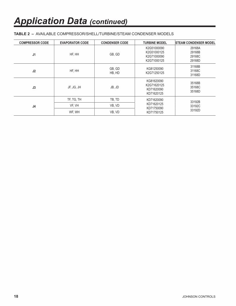
Application Data (continued)TABLE 2 – AVAILABLE COMPRESSOR/SHELL/TURBINE/STEAM CONDENSER MODELS
COMPRESSOR CODE EVAPORATOR CODE CONDENSER CODE TURBINE MODEL STEAM CONDENSER MODEL
J1 HF, HH GB, GD
K2G51000090K2G51000125K2G71000090K2G71000125
29168A29168B29168C29168D
J2 HF, HH GB, GDHB, HD
KG81250090K2G71250125
31168B31168C31168D
J3 JF, JG, JH JB, JD
KG81620090K2G71620125KD71620090KD71620125
35168B35168C35168D
J4
TF, TG, TH TB, TD KD71620090KD71620125KD71750090KD71750125
33192B33192C33192D
VF, VH VB, VD
WF, WH VB, VD
FORM160 .67-EG1(906)
JOHNSONCONTROLS 19
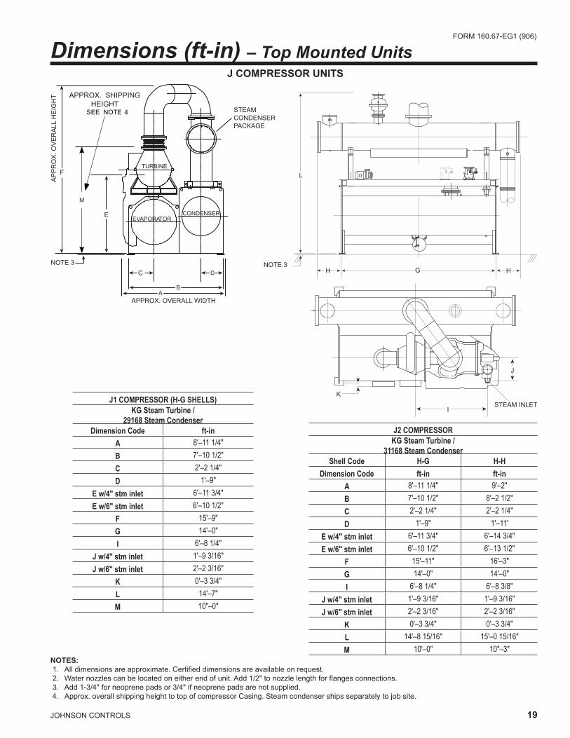
Dimensions (ft-in) – Top Mounted Units
NOTES: 1. All dimensions are approximate. Certified dimensions are available on request. 2. Water nozzles can be located on either end of unit. Add 1/2" to nozzle length for flanges connections. 3. Add 1-3/4" for neoprene pads or 3/4" if neoprene pads are not supplied.4 .Approx .overallshippingheighttotopofcompressorCasing .Steamcondensershipsseparatelytojobsite .
K
ISTEAM INLET
J
NOTE 3
EVAPORATORCONDENSER
TURBINE
APPROX. OVERALL WIDTH
AP
PR
OX
. OV
ER
ALL
HE
IGH
T
STEAMCONDENSERPACKAGE
E
F
C
SEE NOTE 4
M
APPROX. SHIPPING HEIGHT
L
H G HNOTE 3
j COMPRESSOR UNITS
J1 COMPRESSOR (H-G SHELLS)KG Steam Turbine /
29168 Steam CondenserDimension Code ft-in
A 8'–11 1/4"B 7'–10 1/2"C 2'–2 1/4"D 1'–9"
E w/4" stm inlet 6'–11 3/4"E w/6" stm inlet 6'–10 1/2"
F 15'–9"G 14'–0"I 6'–8 1/4"
J w/4" stm inlet 1'–9 3/16"J w/6" stm inlet 2'–2 3/16"
K 0'–3 3/4"L 14'–7"M 10"–0"
J2 COMPRESSORKG Steam Turbine /
31168 Steam CondenserShell Code H-G H-H
Dimension Code ft-in ft-inA 8'–11 1/4" 9'–2"B 7'–10 1/2" 8'–2 1/2"C 2'–2 1/4" 2'–2 1/4"D 1'–9" 1'–11'
E w/4" stm inlet 6'–11 3/4" 6'–14 3/4"E w/6" stm inlet 6'–10 1/2" 6'–13 1/2"
F 15'–11" 16'–3"G 14'–0" 14'–0"I 6'–8 1/4" 6'–8 3/8"
J w/4" stm inlet 1'–9 3/16" 1'–9 3/16"J w/6" stm inlet 2'–2 3/16" 2'–2 3/16"
K 0'–3 3/4" 0'–3 3/4"L 14'–8 15/16" 15'–0 15/16"M 10'–0" 10"–3"
20 JOHNSONCONTROLS
�
�
�
�
�
�
���������������������������������������������������
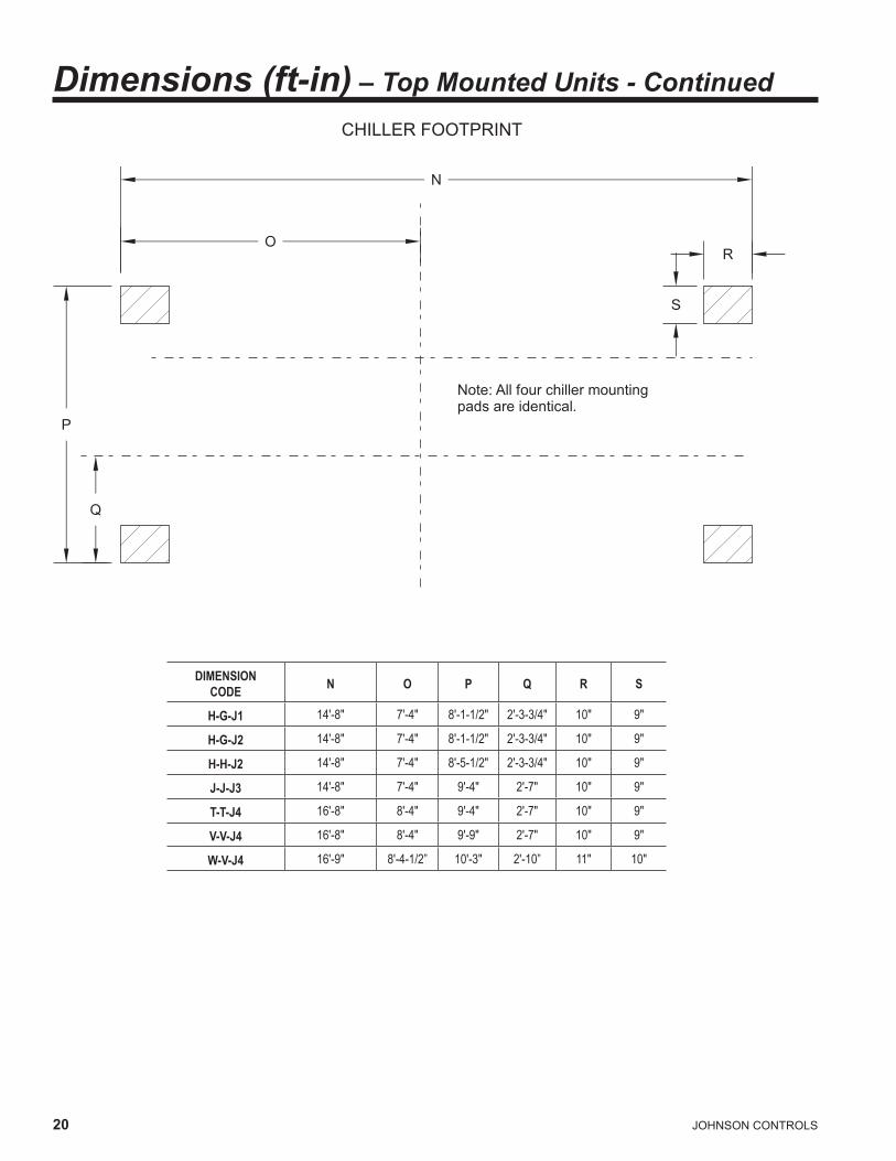
DIMENSIONCODE N O P Q R S
H-G-J1 14'-8" 7'-4" 8'-1-1/2" 2'-3-3/4" 10" 9"
H-G-J2 14'-8" 7'-4" 8'-1-1/2" 2'-3-3/4" 10" 9"
H-H-J2 14'-8" 7'-4" 8'-5-1/2" 2'-3-3/4" 10" 9"
J-J-J3 14'-8" 7'-4" 9'-4" 2'-7" 10" 9"
T-T-J4 16'-8" 8'-4" 9'-4" 2'-7" 10" 9"
V-V-J4 16'-8" 8'-4" 9'-9" 2'-7" 10" 9"
W-V-J4 16'-9" 8'-4-1/2” 10'-3" 2'-10” 11" 10"
Dimensions (ft-in) – Top Mounted Units - ContinuedCHILLER FOOTPRINT
FORM160 .67-EG1(906)
JOHNSONCONTROLS 21
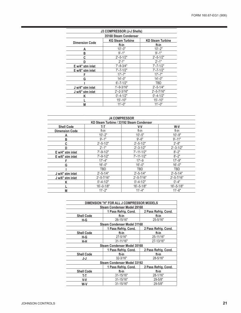
J3 COMPRESSOR (J-J Shells)35168 Steam Condenser
Dimension Code KG Steam Turbine KD Steam Turbineft-in ft-in
A 10'–0" 10'–2"B 9'–1" 9'–1"C 2'–5-1/2" 2'–5-1/2"D 2'-1" 2'–1"
E w/4" stm inlet 7'–8-3/4" 7'–7-1/2"E w/6" stm inlet 7'–7-1/2" 7'–7-1/2"
F 17'–7" 17'–7"G 14'–0" 14'–0"I 6'–7-1/2" TBD
J w/4" stm inlet 1'–9-3/16" 2'–5-1/4"J w/6" stm inlet 2'–2-3/16" 2'–5-7/16"
K 0'–4-1/2" 0'–4-1/2"L 15'–10" 15'–10"M 11'–0" 11'–0"
J4 COMPRESSORKD Steam Turbine / 33192 Steam Condenser
Shell Code T-T V-V W-VDimension Code ft-in ft-in ft-in
A 10'–2" 10'–5" 10'–9"B 9'–1" 9'–6" 9'–11"C 2'–5-1/2" 2'–5-1/2" 2'–8"D 2'–1" 2'–3-1/2" 2'–3-1/2"
E w/4" stm inlet 7'–9-1/2" 7'–11-1/2" 8'–2"E w/6" stm inlet 7'–9-1/2" 7'–11-1/2" 8'–2"
F 17'–4" 17'–9 17'–9"G 16'–0" 16'–0" 16'–0"I TBD TBD TBD
J w/4" stm inlet 2'–5-1/4" 2'–5-1/4" 2'–5-1/4"J w/6" stm inlet 2'–5-7/16" 2'–5-7/16" 2'–5-7/16"
K 0'–4-1/2" 0'–4-1/2" 0'–4"L 16'–0-1/8" 16'–5-1/8" 16'–5-1/8"M 11'–2" 11'–4" 11'–6"
DIMENSION "H" FOR ALL J COMPRESSOR MODELSSteam Condenser Model 29168
1 Pass Refrig. Cond. 2 Pass Refrig. Cond.Shell Code ft-in ft-in
H-G 26-15/16" 25-5/16"Steam Condenser Model 31168
1 Pass Refrig. Cond. 2 Pass Refrig. Cond.Shell Code ft-in ft-in
H-G 27-5/16" 25-11/16"H-H 31-11/16" 27-13/16"
Steam Condenser Model 351681 Pass Refrig. Cond. 2 Pass Refrig. Cond.
Shell Code ft-in ft-inJ-J 32-3/16" 28-5/16"
Steam Condenser Model 331921 Pass Refrig. Cond. 2 Pass Refrig. Cond.
Shell Code ft-in ft-inT-T 31-15/16" 28-1/16"V-V 31-15/16" 29-5/8"W-V 31-15/16" 29-5/8"

22 JOHNSONCONTROLS
FRONT
OF
UNIT
FRONT
OF
UNIT
FRONT
OF
UNIT
COMPRESSOR END TURBINE END
COMPRESSOR END TURBINE END
COMPRESSOR END TURBINE END
FLOOR
LINE
FLOOR
LINE
FLOOR
LINE
AA AA
BB BB
BB BB
FF
FF
FF FF
FF
FF1"
1"
1" 1"
1"
1"
A
B
F N
C J K
H
EE EE EE EE
1-PASS
2-PASS
3-PASS
Dimensions (ft-in) – Nozzle ArrangementsEVAPORATORS – COMPACT WATER BOXES – j COMPRESSOR UNITS
NOTES: 1. Standard water nozzles are furnished as welding stub-outs with Victaulic grooves, allowing the option of welding, flanges, or use of Victaulic
couplings. Factory-installed, class 150 (ANSI B16.5, round slip-on, forged carbon steel with 1/16" raised face), water flanged nozzles are optional (add 1/2" to nozzle length). Companion flanges, nuts, bolts, and gaskets are not furnished.
2. Add 1" if neoprene pads are supplied. 3. One-, two- and three-pass nozzle arrangements are available only in pairs shown and for all shell codes. Any pair of evaporator nozzles may
beusedincombinationwithanypairofcondensernozzles .4 . Connectedpipingshouldallowforremovalofcompactwaterboxesfortubeaccessandcleaning .
NOZZLEARRANGEMENTS
NO. OFPASSES
EVAPORATOR
IN OUT
1A HH A
NOZZLEARRANGEMENTS
NO. OFPASSES
EVAPORATOR
IN OUT
2
B CC BJ KK J
NOZZLEARRANGEMENTS
NO. OFPASSES
EVAPORATORIN OUT
3F NN F
EVAP.SHELLCODE
NOZZLE PIPE SIZEEVAPORATOR
NOZZLE DIMENSIONSNO. OF PASSES 1-PASS 2-PASS 3-PASS
1 2 3 AA2 FF BB2 EE FF BB2 FFHF 16" 12" 10" 2'–0-3/4" 2'–2-1/4" 2'–0-3/4" 11" 2'–2-1/4" 2'–0-3/4" 2'–2-1/4"HH 16" 12" 10" 2'–1-1/2" 2'–2-1/4" 2'–1-1/2" 11" 2'–2-1/4" 2'–1-1/2" 2'–2-1/4"J 18" 14" 12" 2'–1-3/4" 2'–5-1/2" 2'–1-3/4" 11" 2'–5-1/2" 2'–1-3/4" 2'–5-1/2"T 18" 14" 12" 2'–1-3/4" 2'–5-1/2" 2'–1-3/4" 11" 2'–5-1/2" 2'–1-3/4" 2'–5-1/2"V 20" 16" 12" 2'–5-1/4" 2'–5-1/2" 2'–5-1/4" 1'–1" 2'–5-1/2" 2'–5-1/4" 2'–5-1/2"W 20" 18" 14" 2'–7-1/4" 2'–8" 2'–7-1/4" 1'–3" 2'–8" 2'–7-1/4" 2'–8"
FORM160 .67-EG1(906)
JOHNSONCONTROLS 23
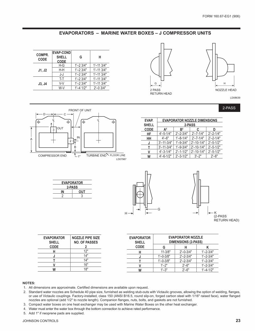
EVAPORATORS – MARINE WATER BOXES – j COMPRESSOR UNITS
A
B
3
TURBINE ENDCOMPRESSOR END FLOOR LINE
2
IN
OUT
D C
1"
FRONT OF UNIT2-PASS
LD07987
NOTES: 1. All dimensions are approximate. Certified dimensions are available upon request. 2. Standard water nozzles are Schedule 40 pipe size, furnished as welding stub-outs with Victaulic grooves, allowing the option of welding, flanges,
or use of Victaulic couplings. Factory-installed, class 150 (ANSI B16.5, round slip-on, forged carbon steel with 1/16" raised face), water flanged nozzles are optional (add 1/2" to nozzle length). Companion flanges, nuts, bolts, and gaskets are not furnished.
3 . CompactwaterboxesononeheatexchangermaybeusedwithMarineWaterBoxesontheotherheatexchanger .4 . Watermustenterthewaterboxthroughthebottomconnectiontoachieveratedperformance . 5. Add 1" if neoprene pads are supplied.
G
K
(2-PASS
RETURN HEAD)
H
LD08639
NOZZLE HEAD2 PASS
RETURN HEAD
G H
COMPR.CODE
EVAP-CONDSHELL CODE
G H
J1, J2H-G 1'–2 3/4" 1'–11 3/4"H-H 1'–2 3/4" 1'–11 3/4"J-J 1'–2 3/4" 1'–11 3/4"
J3, J4T-T 1'–2 3/4" 1'–11 3/4"V-V 1'–2 3/4" 1'–11 3/4"W-V 1'–4 1/2" 2'–0 3/4"
EVAP.SHELLCODE
EVAPORATOR NOZZLE DIMENSIONS2-PASS
A5 B5 C DHF 4'–5-1/4" 2'–2-3/4" 2'–7-1/4" 2'–2-1/4"HH 4'–6" 1'–8-1/4" 2'–7-1/4" 2'–2-1/4"J 3'–11-3/4" 1'–9-3/4" 2'–10-1/4" 2'–5-1/2"T 3'–11-3/4" 1'–9-3/4" 2'–10-1/4" 2'–5-1/2"V 4'–3-1/4" 2'–1-1/2" 2'–10-1/4" 2'–5-1/2"W 4'–6-1/2" 2'–3-1/2" 3'–2" 2'–6"
EVAPORATOR2-PASS
IN OUT2 3
EVAPORATORSHELLCODE
NOZZLE PIPE SIZENO. OF PASSES
2H 12"J 14"T 14"V 16"W 18"
EVAPORATORSHELLCODE
EVAPORATOR NOZZLEDIMENSIONS (2-PASS)
G H KH 11-3/8" 2'–0-3/4" 1'–2-3/4"J 1'–0-3/8" 2'–2-3/4" 1'–2-3/4"T 1'–0-3/8" 2'–2-3/4" 1'–2-3/4"V 1'–2" 2'–6" 1'–2-3/4"W 1'–3" 2'–6" 1'–4-1/2"

24 JOHNSONCONTROLS
CONDENSERS – MARINE WATER BOXES – j COMPRESSOR UNITS
LD07991
D
18
A 17
C
B
SEE NOTE 6
B
C
A12
13
D
1" 1" 1"1"
1"1"
COMPRESSOR END TURBINE END
COMPRESSOR END COMPRESSOR END
COMPRESSOR END
11 16
D D
FLOOR LINE FLOOR LINE
FLOOR LINE FLOOR LINE
A
11 16SEE NOTE 6
D D
A
FRONT OF UNIT FRONT OF UNIT
FRONT OF UNIT FRONT OF UNIT
1-PASS
2-PASS
1"1"
TURBINE END TURBINE END
TURBINE END
IN OUT
OUT
IN IN
OUT
OUT IN
NOTES: 1. All dimensions are approximate. Certified dimensions are available upon request. 2. Standard water nozzles are Schedule 40 pipe size, furnished as welding stub-outs with Victaulic grooves, allowing the option of welding, flanges, or
use of Victaulic couplings. Factory-installed, class 150 (ANSI B16.5, round slip-on, forged carbon steel with 1/16" raised face), water flanged nozzles are optional (add 1/2" to nozzle length). Companion flanges, nuts, bolts, and gaskets are not furnished.
3 . One-andtwo-passnozzlearrangementsareavailableonlyinpairsshownandforallshellcodes .Anypairofevaporatornozzlesmaybeusedincombinationwithanypairofcondensernozzles .CompactwaterboxesononeheatexchangermaybeusedwithMarineWaterBoxesontheotherheatexchanger .
4 . Condenserwatermustenter thewaterbox through thebottomconnection forproperoperationof thesub-cooler toachieve ratedperfor-mance .
5. Add 1" if neoprene pads are supplied. 6. “G” Condenser Water Boxes are square; other codes are round as shown.
COND.SHELLCODE
CONDENSER NOZZLE DIMENSIONS1-PASS 2-PASS
A5 D A5 B5 C DG 5'–9-3/4" 1'–9" 5'–9-3/4" 2'–8-3/4" 2'–5" 1'–9"H 5'–11" 1'–11" 5'–10-1/4" 2'–0-3/4" 2'–1" 1'–11"J 6'–3-3/8" 2'–1" 6'–2-3/8" 2'–1-1/2" 2'–1-1/8" 2'–1"T 6'–3-3/8" 2'–1" 6'–2-3/8" 2'–1-1/2" 2'–1-1/8" 2'–1"V 6'–8-3/4" 2'–3-1/2" 6'–8-1/8" 2'–1-3/4" 2'–5-3/8" 2'–3-1/2"
Dimensions (ft-in) – Nozzle Arrangements

FORM160 .67-EG1(906)
JOHNSONCONTROLS 25
CONDENSER1-PASS
IN OUT11 1616 11
CONDENSER2-PASS
IN OUT12 1317 18
CONDENSERSHELLCODE
COND. NOZZLEDIMENSIONS (1-PASS)
G HG 1'–1 1/4" 2'–4 3/8"H 1'–3 1/2" 2'–8 3/4"j 1'–3 1/2" 2'–8 7/8"T 1'–3 1/2" 2'–8 7/8"V 1'–3 1/2" 2'–9 3/8"
TUBE
SHEET
G
H
TUBE
SHEET
(2-PASS
RETURN HEAD)K
COND.SHELLCODE
NOZZLE PIPE SIZENO. OF PASSES
1 2G 16" 14"H 20" 16"J 20" 16"T 20" 16"V 20" 18"
CONDENSERSHELLCODE
COND. NOZZLEDIMENSIONS (2-PASS)
G H KG 1'–0 1/4" 2'–2 3/8" 0'–5 7/8"H 1'–1 5/8" 2'–5" 0'–11 5/8"J 1'–1 5/8" 2'–5 1/8" 1'–0 1/2"T 1'–1 5/8" 2'–5 1/8" 1'–0 1/2"V 1'–2 1/4" 2'–6 3/4" 1'–1 5/8"
CONDENSERS – MARINE WATER BOXES – j COMPRESSOR UNITS
26 JOHNSONCONTROLS
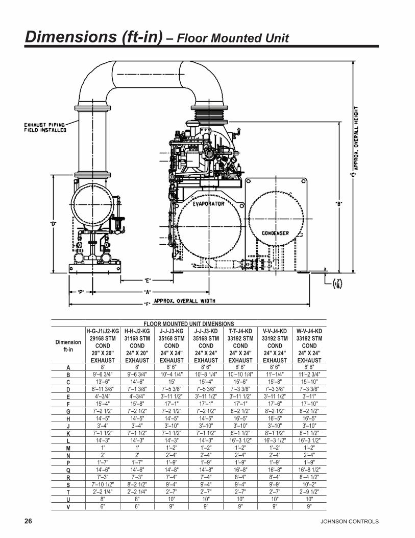
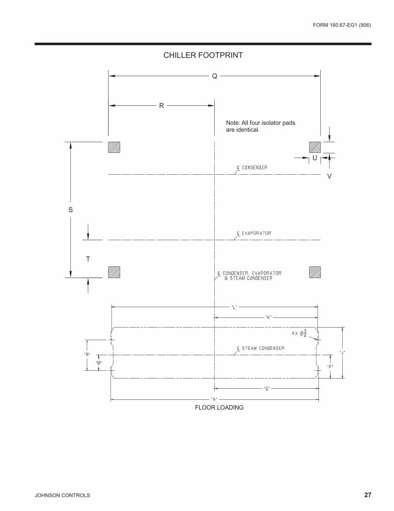
Dimensions (ft-in) – Floor Mounted Unit
FLOOR MOUNTED UNIT DIMENSIONS
Dimension ft-in
H-G-J1/J2-KG 29168 STM
COND 20" X 20" EXHAUST
H-H-J2-KG 31168 STM
COND 24" X 20" EXHAUST
J-J-J3-KG 35168 STM
COND 24" X 24" EXHAUST
J-J-J3-KD 35168 STM
COND 24" X 24" EXHAUST
T-T-J4-KD 33192 STM
COND 24" X 24" EXHAUST
V-V-J4-KD 33192 STM
COND 24" X 24" EXHAUST
W-V-J4-KD 33192 STM
COND 24" X 24" EXHAUST
A 8' 8' 8' 6" 8' 6" 8' 6" 8' 6" 8' 8" B 9'–6 3/4" 9'–6 3/4" 10'–4 1/4" 10'–8 1/4" 10'–10 1/4" 11'–1/4" 11'–2 3/4" C 13'–6" 14'–6" 15' 15'–4" 15'–6" 15'–8" 15'–10" D 6'–11 3/8" 7'–1 3/8" 7'–5 3/8" 7'–5 3/8" 7'–3 3/8" 7'–3 3/8" 7'–3 3/8" E 4'–3/4" 4'–3/4" 3'–11 1/2" 3'–11 1/2" 3'–11 1/2" 3'–11 1/2" 3'–11" F 15'–4" 15'–8" 17'–1" 17'–1" 17'–1" 17'–6" 17'–10" G 7'–2 1/2" 7'–2 1/2" 7'–2 1/2" 7'–2 1/2" 8'–2 1/2" 8'–2 1/2" 8'–2 1/2" H 14'–5" 14'–5" 14'–5" 14'–5" 16'–5" 16'–5" 16'–5" J 3'–4" 3'–4" 3'–10" 3'–10" 3'–10" 3'–10" 3'–10" K 7'–1 1/2" 7'–1 1/2" 7'–1 1/2" 7'–1 1/2" 8'–1 1/2" 8'–1 1/2" 8'–1 1/2" L 14'–3" 14'–3" 14'–3" 14'–3" 16'–3 1/2" 16'–3 1/2" 16'–3 1/2" M 1' 1' 1'–2" 1'–2" 1'–2" 1'–2" 1'–2" N 2' 2' 2'–4" 2'–4" 2'–4" 2'–4" 2'–4" P 1'–7" 1'–7" 1'–9" 1'–9" 1'–9" 1'–9" 1'–9" Q 14'–6" 14'–6" 14'–8" 14'–8" 16'–8" 16'–8" 16'–8 1/2" R 7'–3" 7'–3" 7'–4" 7'–4" 8'–4" 8'–4" 8'–4 1/2" S 7'–10 1/2" 8'–2 1/2" 9'–4" 9'–4" 9'–4" 9'–9" 10'–2" T 2'–2 1/4" 2'–2 1/4" 2'–7" 2'–7" 2'–7" 2'–7" 2'–9 1/2" U 8" 8" 10" 10" 10" 10" 10" V 6" 6" 9" 9" 9" 9" 9"
FORM160 .67-EG1(906)
JOHNSONCONTROLS 27
�������������
�
�
�
�
�������������������������������������������
�
�
CHILLER FOOTPRINT

2� JOHNSONCONTROLS
B
A
OUTLETRELIEFVALVE EXHAUST IN
INLET
C
D
APPROX. OVERALL WIDTH
E
OUTSIDE OF
CHILLER
INSIDE OF CHILLER
LD08001
Dimensions (ft-in) – Steam Condenser
STEAM CONDENSER MODEL29168 31168 35168 33192
Dimension Code ft-in ft-in ft-in ft-inB 14'–5" 14'–5" 14'–5" 16'–5"C 3'–4" 3'–4" 3'–10" 3'–10"D 4'–0" 4'–0" 4'–4" 4'–3"E 6'–11-3/8" 7'–1-3/8" 7'–5-3/8" 7'–3-3/8"F 2'–0" 2'–0" 2'–4" 2'–4"G 1'–0" 1'–0" 1'–2" 1'–2"H 1'–7" 1'–7" 1'–9" 1'–9"I 3'–4" 3'–4" 3'–10" 3'–10"J 14'–3" 14'–3" 14'–3" 16'–3"K 14'–5" 14'–5" 14'–5" 16'–5"
DIMENSION “A” FOR ALL MODELS
Model 1 Pass Refrig. Cond.ft-in
2 Pass Refrig. Cond.ft-in
29168 18–5-7/8” 18’–2-5/8”31168 w/H-G shells 18’–6-5/8” 18’–3-3/8”31168 w/H-H shells 19’–3-3/8” 18’–7-5/8”
35168 19’–4-3/8” 18’–8-5/8”33192 w/T-T shells 21’–3-7/8” 20’–8-1/8”33192 w/V-V shells 21’–3-7/8” 20’–11-1/4”33192 w/W-V shells 21’–3-7/8” 20’–11-1/4”
FORM160 .67-EG1(906)
JOHNSONCONTROLS 29
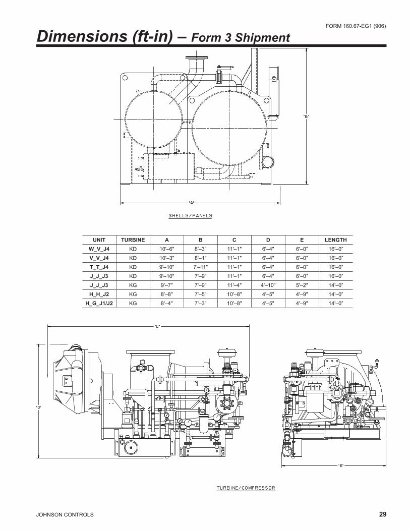
Dimensions (ft-in) – Form 3 Shipment
UNIT TURBINE A B C D E LENGTHW_V_j4 KD 10'–6" 8'–3" 11'–1" 6'–4" 6'–0” 16'–0”
V_V_j4 KD 10'–3" 8'–1" 11'–1" 6'–4" 6'–0” 16'–0”
T_T_j4 KD 9'–10" 7'–11" 11'–1" 6'–4" 6'–0” 16'–0”
j_j_j3 KD 9'–10" 7'–9" 11'–1" 6'–4" 6'–0” 16'–0”
j_j_j3 KG 9'–7" 7'–9" 11'–4" 4'–10" 5'–2" 14'–0”
H_H_j2 KG 8'–8" 7'–5" 10'–8" 4'–5" 4'–9" 14'–0”
H_G_j1/j2 KG 8'–4" 7'–3" 10'–8" 4'–5" 4'–9" 14'–0”

30 JOHNSONCONTROLS
UNIT TURBINE A B C D E F G LENGTHW_V_j4 KD 5'–10" 8'–3" 11'–1" 6'–4" 6'–0” 8'–1' 5’–11” 16'–0”
V_V_j4 KD 5'–5" 8'–1" 11'–1" 6'–4" 6'–0” 7'–11" 5’–9” 16'–0”
T_T_j4 KD 5'–5" 7'–11" 11'–1" 6'–4" 6'–0” 7'–8” 5’–4” 16'–0”
j_j_j3 KD 5'–5" 7'–9" 11'–1" 6'–4" 6'–0” 7’–7” 7’–7” 16'–0”
j_j_j3 KG 5'–5" 7'–9" 11'–4" 4'–10" 5'–2" 7’–7” 7’–7” 14'–0”
H_H_j2 KG 4'–10" 7'–5" 10'–8" 4'–5" 4'–9" 7’–1” 4’–11” 14'–0”
H_G_j1/j2 KG 4'–10" 7'–3" 10'–8" 4'–5" 4'–9" 6’–10” 4’–7” 14'–0”
Dimensions (ft-in) – Form 7 Shipment

FORM160 .67-EG1(906)
JOHNSONCONTROLS 31
INTENTIONALLYLEFTBLANK

32 JOHNSONCONTROLS
Dimensions (mm) – Top Mounted Unitj COMPRESSOR UNITS
NOTES: 1. All dimensions are approximate. Certified dimensions are available on request. 2. Water nozzles can be located on either end of unit. Add 13mm to nozzle length for flanges connections.3 . Add44mmforneoprenepadsor19mmifneoprenepadsarenotsupplied .4 .Approximateoverallshippingheighttotopofcompressorcasing .Steamcondensershippedseparatelytosite .
K
ISTEAM INLET
J
NOTE 3
EVAPORATORCONDENSER
TURBINE
APPROX. OVERALL WIDTH
AP
PR
OX
. OV
ER
ALL
HE
IGH
T
STEAMCONDENSERPACKAGE
E
F
C
SEE NOTE 4
M
APPROX. SHIPPING HEIGHT
L
H G HNOTE 3
LD08000
J1 COMPRESSOR (H-G SHELLS) KG Steam Turbine / 29168 Steam Condenser Dimension Code mm
A 2,725B 2,401C 667D 534
E w/4 stm inlet " 2,128E w/6 stm inlet " 2,096
F 4,801G 4,268I 2,039
J w/4 stm inlet " 539J w/6 stm inlet " 665
K 96L 4,445M 3,048
J2 COMPRESSOR KG Steam Turbine / 31168 Steam Condenser
Shell Code H-G H-H Dimension Code mm mm
A 2,725 2,794B 2,401 2,502C 667 667D 534 585
E w/4 stm inlet " 2,128 2,204E w/6 stm inlet " 2,096 2,172
F 4,852 4,953G 4,268 4,268I 2,039 2,042
J w/4 stm inlet " 539 539J w/6 stm inlet " 665 665
K 96 96L 4,495 4,596M 3,048 3,124
FORM160 .67-EG1(906)
JOHNSONCONTROLS 33
�
�
�
�
�
�
���������������������������������������������������
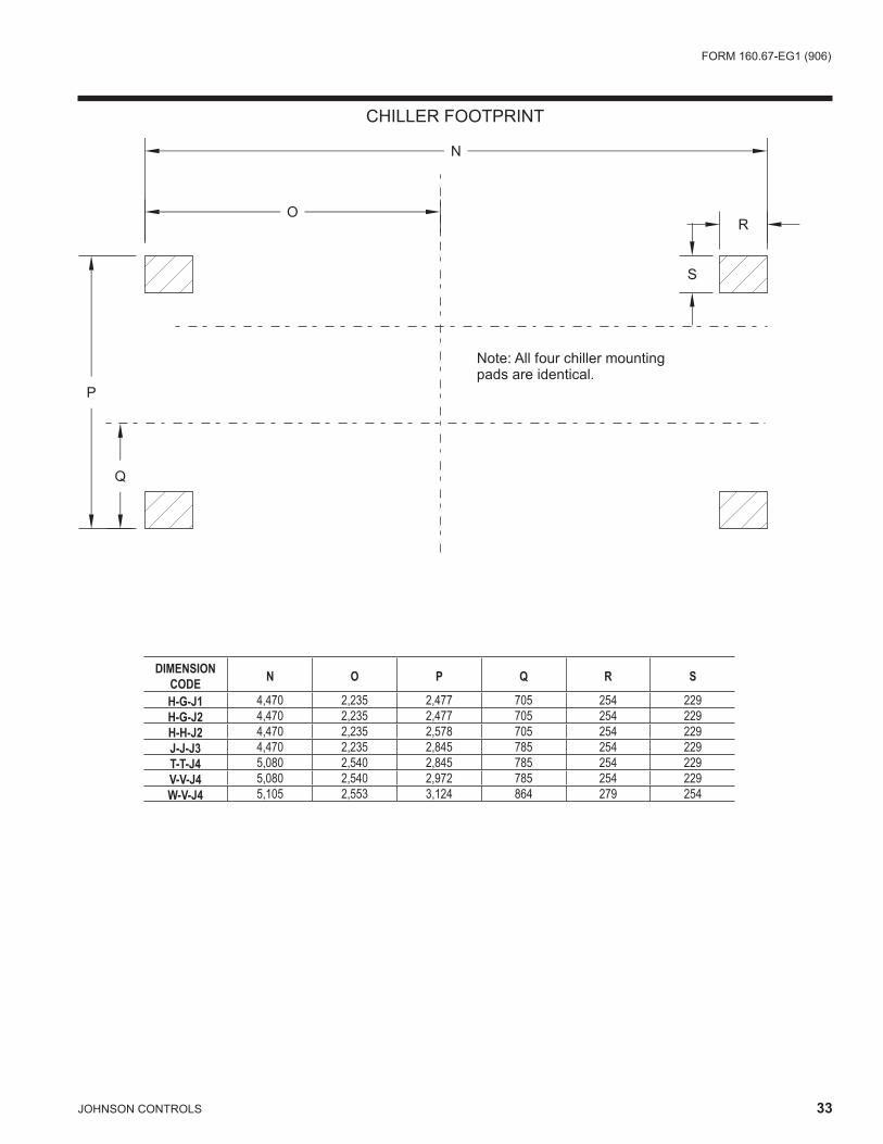
DIMENSIONCODE N O P Q R S
H-G-J1 4,470 2,235 2,477 705 254 229H-G-J2 4,470 2,235 2,477 705 254 229H-H-J2 4,470 2,235 2,578 705 254 229J-J-J3 4,470 2,235 2,845 785 254 229T-T-J4 5,080 2,540 2,845 785 254 229V-V-J4 5,080 2,540 2,972 785 254 229W-V-J4 5,105 2,553 3,124 864 279 254
CHILLER FOOTPRINT
34 JOHNSONCONTROLS
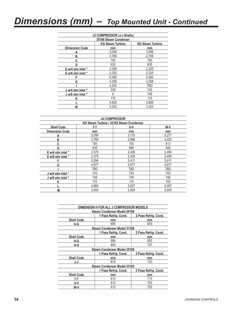
J3 COMPRESSOR (J-J Shells) 35168 Steam Condenser
KG Steam Turbine KD Steam Turbine Dimension Code mm mm
A 3,048 3,099B 2,769 2,769C 750 750D 635 635
E w/4 stm inlet " 2,356 2,325E w/6 stm inlet " 2,325 2,325
F 5,360 5,360G 4,268 4,268I 2,020 TBD
J w/4 stm inlet " 539 743J w/6 stm inlet " 6 748
K 115 115L 4,826 4,826M 3,353 3,353
J4 COMPRESSOR KD Steam Turbine / 33192 Steam Condenser
Shell Code T-T V-V W-V Dimension Code mm mm mm
A 3,099 3,175 3,277B 2,769 2,896 3,023C 750 750 813D 635 699 699
E w/4 stm inlet " 2,375 2,426 2,490E w/6 stm inlet " 2,375 2,426 2,490
F 5,284 5,411 5,411G 4,877 4,877 4,877I TBD TBD TBD
J w/4 stm inlet " 743 743 743J w/6 stm inlet " 748 748 748
K 115 115 102L 4,880 5,007 5,007 M 3,404 3,454 3,505
DIMENSION H FOR ALL J COMPRESSOR MODELS Steam Condenser Model 29168
1 Pass Refrig. Cond. 2 Pass Refrig. Cond. Shell Code mm mm
H-G 685 643Steam Condenser Model 31168
1 Pass Refrig. Cond. 2 Pass Refrig. Cond. Shell Code mm mm
H-G 694 653H-H 805 707
Steam Condenser Model 35168 1 Pass Refrig. Cond. 2 Pass Refrig. Cond.
Shell Code mm mm J-J 818 720
Steam Condenser Model 33192 1 Pass Refrig. Cond. 2 Pass Refrig. Cond.
Shell Code mm mm T-T 812 713V-V 812 753W-V 812 753
Dimensions (mm) – Top Mounted Unit - Continued

FORM160 .67-EG1(906)
JOHNSONCONTROLS 35
FRONTOF
UNIT
FRONTOF
UNIT
FRONTOF
UNIT
COMPRESSOR END TURBINEEND
COMPRESSOR END TURBINEEND
COMPRESSOR END TURBINEEND
FLOORLINE
FLOORLINE
FLOORLINE
AA AA
BB BB
BB BB
FF
FF
FF FF
FF
FF25
25
1" 1"
25
25
A
B
F N
C J K
H
EE EE EE EE
1-PASS
2-PASS
3-PASS
Dimensions (mm) – Nozzle ArrangementsEVAPORATORS – COMPACT WATER BOXES – j COMPRESSOR UNITS
LD07990A
NOZZLE ARRANGEMENTS NO. OF EVAPORATOR PASSES IN OUT 3 F N N F
EVAPORATOR EVAP. NOZZLE PIPE SIZE NOZZLE DIMENSIONS (mm) SHELL NO. OF PASSES 1-PASS 2-PASS 3-PASS CODE 1 2 3 AA2 F F BB2 EE FF BB2 FF H F 16" 12" 10" 629 667 629 279 667 629 667 HH 16" 12" 10" 648 667 648 279 667 648 667 j 18" 14" 12" 654 749 654 279 749 654 749 T 18" 14" 12" 654 749 654 279 749 654 749 V 20" 16" 12" 743 749 743 330 749 743 749 W 20" 18" 14" 794 813 794 381 813 794 813
NOZZLE ARRANGEMENTS NO. OF EVAPORATOR PASSES IN OUT 1 A H H A
NOZZLE ARRANGEMENTS NO. OF EVAPORATOR PASSES IN OUT B C 2 C B J K K J
NOTES: 1. Standard water nozzles are furnished as welding stub-outs with Victaulic grooves, allowing the option of welding, flanges, or use of Victaulic
couplings. Factory-installed, class 150 (ANSI B16.5, round slip-on, forged carbon steel with 1.6 mm raised face), water flanged nozzles are optional (add 13 mm to nozzle length). Companion flanges, nuts, bolts, and gaskets are not furnished.
2 . Add25mmifneoprenepadsaresupplied . 3. One-, two- and three-pass nozzle arrangements are available only in pairs shown and for all shell codes. Any pair of evaporator nozzles may
beusedincombinationwithanypairofcondensernozzles .4 . Connectedpipingshouldallowforremovalofcompactwaterboxesfortubeaccessandcleaning .
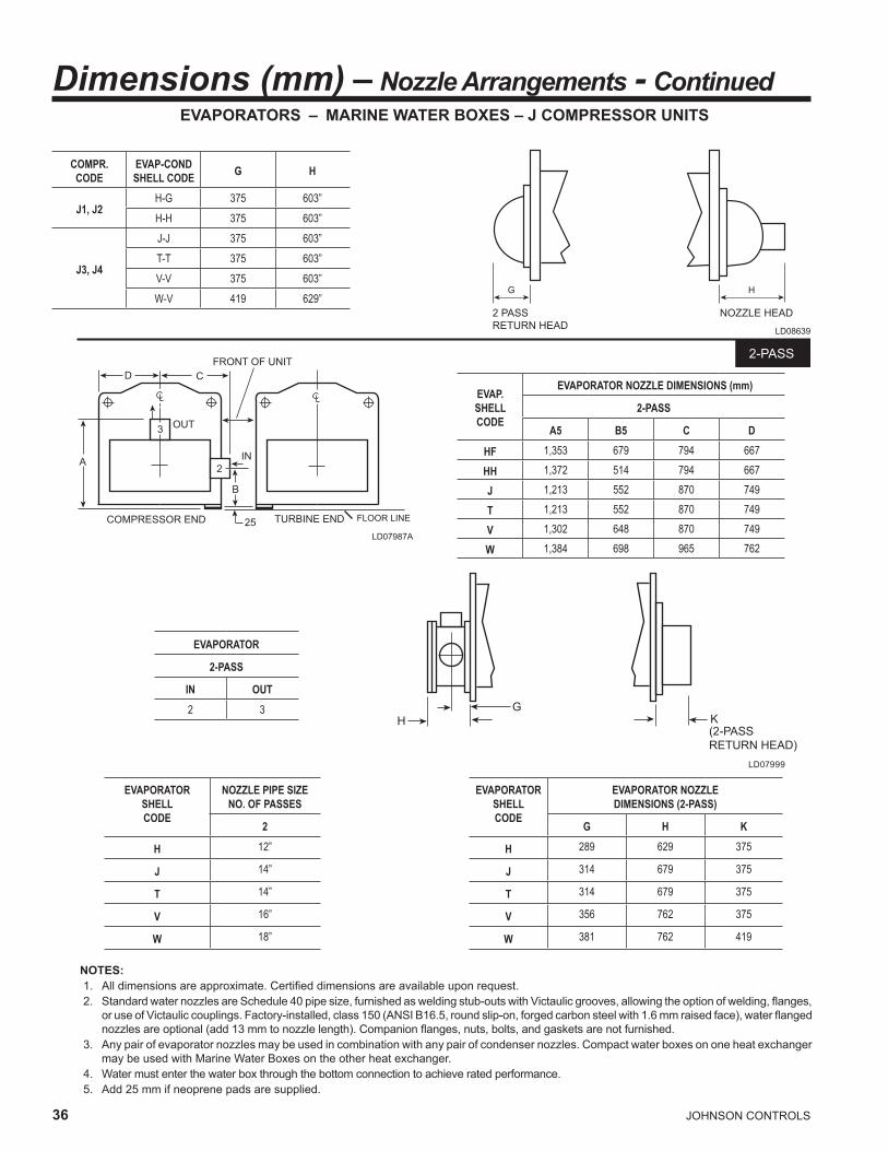
36 JOHNSONCONTROLS
A
B
3
TURBINE ENDCOMPRESSOR END FLOOR LINE
2
IN
OUT
D C
25
FRONT OF UNIT2-PASS
EVAPORATORS – MARINE WATER BOXES – j COMPRESSOR UNITS
LD07987A
NOTES: 1. All dimensions are approximate. Certified dimensions are available upon request. 2. Standard water nozzles are Schedule 40 pipe size, furnished as welding stub-outs with Victaulic grooves, allowing the option of welding, flanges,
or use of Victaulic couplings. Factory-installed, class 150 (ANSI B16.5, round slip-on, forged carbon steel with 1.6 mm raised face), water flanged nozzles are optional (add 13 mm to nozzle length). Companion flanges, nuts, bolts, and gaskets are not furnished.
3 . Anypairofevaporatornozzlesmaybeusedincombinationwithanypairofcondensernozzles .CompactwaterboxesononeheatexchangermaybeusedwithMarineWaterBoxesontheotherheatexchanger .
4 . Watermustenterthewaterboxthroughthebottomconnectiontoachieveratedperformance .5 . Add25mmifneoprenepadsaresupplied .
LD07999
G
K
(2-PASS
RETURN HEAD)
H
LD08639
NOZZLE HEAD2 PASS
RETURN HEAD
G H
Dimensions (mm) – Nozzle Arrangements - Continued
COMPR.CODE
EVAP-CONDSHELL CODE G H
J1, J2H-G 375 603”H-H 375 603”
J3, J4
J-J 375 603”T-T 375 603”V-V 375 603”W-V 419 629”
EVAP.SHELLCODE
EVAPORATOR NOZZLE DIMENSIONS (mm)
2-PASS
A5 B5 C D
HF 1,353 679 794 667
HH 1,372 514 794 667
J 1,213 552 870 749
T 1,213 552 870 749
V 1,302 648 870 749
W 1,384 698 965 762
EVAPORATOR
2-PASS
IN OUT2 3
EVAPORATORSHELLCODE
NOZZLE PIPE SIZENO. OF PASSES
2
H 12”
J 14”
T 14”
V 16”
W 18”
EVAPORATORSHELLCODE
EVAPORATOR NOZZLEDIMENSIONS (2-PASS)
G H K
H 289 629 375
J 314 679 375
T 314 679 375
V 356 762 375
W 381 762 419

FORM160 .67-EG1(906)
JOHNSONCONTROLS 37
CONDENSERS – MARINE WATER BOXES – j COMPRESSOR UNITS
LD07993
SeeNotesonfollowingpages .
D
18
A 17
C
B
SEE NOTE 6
B
C
A12
13
D
25 25 2525
2525
COMPRESSOR END TURBINE END
COMPRESSOR END COMPRESSOR END
COMPRESSOR END
11 16
D D
FLOOR LINE FLOOR LINE
FLOOR LINE FLOOR LINE
A
11 16SEE NOTE 6
D D
A
FRONT OF UNIT FRONT OF UNIT
FRONT OF UNIT FRONT OF UNIT
1-PASS
2-PASS
2525
TURBINE END TURBINE END
TURBINE END
IN INOUT OUT
OUTOUT
ININ
COND.SHELLCODE
CONDENSER NOZZLE DIMENSIONS
1-PASS 2-PASS
A5 D A5 B5 C D
G 1,772 533 1,772 832 737 533
H 1,803 584 1,784 629 635 584
J 1,915 635 1,889 648 638 635
T 1,915 635 1,889 648 638 635
V 2,051 699 2,035 654 746 699
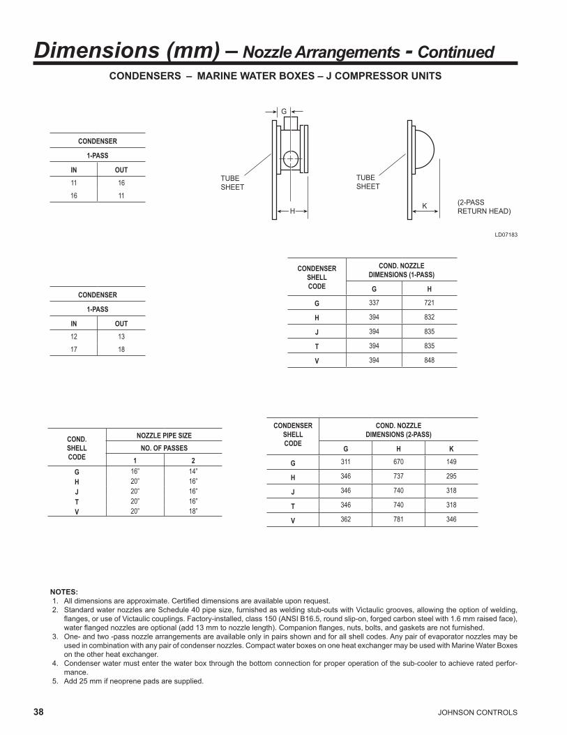
3� JOHNSONCONTROLS
NOTES: 1. All dimensions are approximate. Certified dimensions are available upon request. 2. Standard water nozzles are Schedule 40 pipe size, furnished as welding stub-outs with Victaulic grooves, allowing the option of welding,
flanges, or use of Victaulic couplings. Factory-installed, class 150 (ANSI B16.5, round slip-on, forged carbon steel with 1.6 mm raised face), water flanged nozzles are optional (add 13 mm to nozzle length). Companion flanges, nuts, bolts, and gaskets are not furnished.
3 . One-andtwo-passnozzlearrangementsareavailableonlyinpairsshownandforallshellcodes .Anypairofevaporatornozzlesmaybeusedincombinationwithanypairofcondensernozzles .CompactwaterboxesononeheatexchangermaybeusedwithMarineWaterBoxesontheotherheatexchanger .
4 . Condenserwatermustenterthewaterboxthroughthebottomconnectionforproperoperationofthesub-coolertoachieveratedperfor-mance .
5 . Add25mmifneoprenepadsaresupplied .
TUBE
SHEET
G
H
TUBE
SHEET
(2-PASS
RETURN HEAD)K
LD07183
COND.SHELLCODE
NOZZLE PIPE SIZENO. OF PASSES
1 2G 16” 14”H 20” 16”J 20” 16”T 20” 16”V 20” 18”
Dimensions (mm) – Nozzle Arrangements - ContinuedCONDENSERS – MARINE WATER BOXES – j COMPRESSOR UNITS
CONDENSER
1-PASS
IN OUT11 1616 11
CONDENSER
1-PASS
IN OUT12 1317 18
CONDENSERSHELLCODE
COND. NOZZLEDIMENSIONS (1-PASS)
G H
G 337 721
H 394 832
J 394 835
T 394 835
V 394 848
CONDENSERSHELLCODE
COND. NOZZLEDIMENSIONS (2-PASS)
G H K
G 311 670 149
H 346 737 295
J 346 740 318
T 346 740 318
V 362 781 346

FORM160 .67-EG1(906)
JOHNSONCONTROLS 39
INTENTIONALLYLEFTBLANK
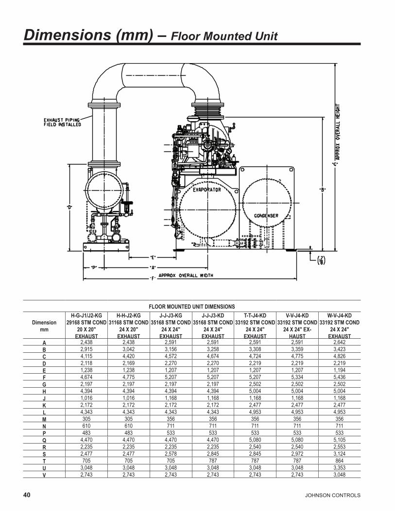
40 JOHNSONCONTROLS
FLOOR MOUNTED UNIT DIMENSIONS
Dimension mm
H-G-J1/J2-KG 29168 STM COND
20 X 20" EXHAUST
H-H-J2-KG 31168 STM COND
24 X 20" EXHAUST
J-J-J3-KG 35168 STM COND
24 X 24" EXHAUST
J-J-J3-KD 35168 STM COND
24 X 24" EXHAUST
T-T-J4-KD 33192 STM COND
24 X 24" EXHAUST
V-V-J4-KD 33192 STM COND
24 X 24" EX-HAUST
W-V-J4-KD 33192 STM COND
24 X 24" EXHAUST
A 2,438 2,438 2,591 2,591 2,591 2,591 2,642B 2,915 3,042 3,156 3,258 3,308 3,359 3,423C 4,115 4,420 4,572 4,674 4,724 4,775 4,826D 2,118 2,169 2,270 2,270 2,219 2,219 2,219E 1,238 1,238 1,207 1,207 1,207 1,207 1,194F 4,674 4,775 5,207 5,207 5,207 5,334 5,436G 2,197 2,197 2,197 2,197 2,502 2,502 2,502H 4,394 4,394 4,394 4,394 5,004 5,004 5,004J 1,016 1,016 1,168 1,168 1,168 1,168 1,168K 2,172 2,172 2,172 2,172 2,477 2,477 2,477L 4,343 4,343 4,343 4,343 4,953 4,953 4,953M 305 305 356 356 356 356 356N 610 610 711 711 711 711 711P 483 483 533 533 533 533 533Q 4,470 4,470 4,470 4,470 5,080 5,080 5,105R 2,235 2,235 2,235 2,235 2,540 2,540 2,553S 2,477 2,477 2,578 2,845 2,845 2,972 3,124T 705 705 705 787 787 787 864U 3,048 3,048 3,048 3,048 3,048 3,048 3,353V 2,743 2,743 2,743 2,743 2,743 2,743 3,048
Dimensions (mm) – Floor Mounted Unit
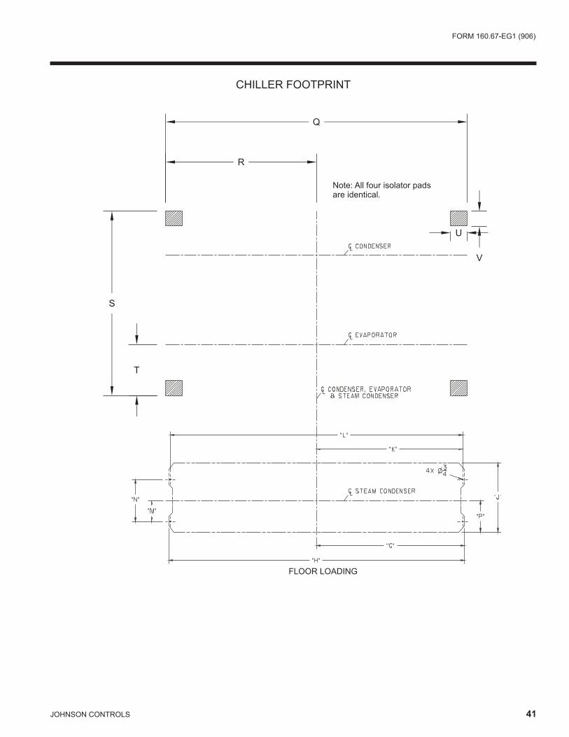
FORM160 .67-EG1(906)
JOHNSONCONTROLS 41
�������������
�
�
�
�
�������������������������������������������
�
�
CHILLER FOOTPRINT

42 JOHNSONCONTROLS
B
A
OUTLETRELIEFVALVE EXHAUST IN
INLET
C
D
APPROX. OVERALL WIDTH
E
OUTSIDE OF
CHILLER
INSIDE OF CHILLER
LD08001
Dimensions (mm) – Steam Condenser
STEAM CONDENSER MODEL29168 31168 35168 33192
Dimension Code mm mm mm mmB 4,395 4,395 4,395 5,004C 1,016 1,016 1,169 1,169D 1,220 1,220 1,321 1,296E 2,118 2,169 2,271 2,220F 610 610 711 711G 305 305 356 356H 483 483 533 533I 1,016 1,016 1168 1168J 4,343 4,343 4,343 4,953K 4,394 4,394 4,394 5,004
Model 1 Pass Refrig. Cond. 2 Pass Refrig. Cond. mm mm
29168 5,636 5,55431168 w/H-G shells 5,655 5,57331168 w/H-H shells 5,877 5,681
35168 5,903 5,70633192 w/T-T shells 6,500 6,30333192 w/V-V shells 6,500 6,38233192 w/W-V shells 6,500 6,382
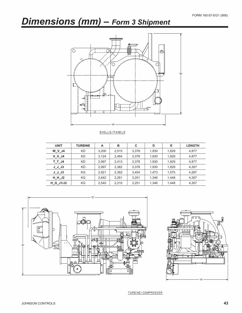
FORM160 .67-EG1(906)
JOHNSONCONTROLS 43
UNIT TURBINE A B C D E LENGTHW_V_j4 KD 3,200 2,515 3,378 1,930 1,829 4,877
V_V_j4 KD 3,124 2,464 3,378 1,930 1,829 4,877
T_T_j4 KD 2,997 2,413 3,378 1,930 1,829 4,877
j_j_j3 KD 2,997 2,362 3,378 1,930 1,829 4,267
j_j_j3 KG 2,921 2,362 3,454 1,473 1,575 4,267
H_H_j2 KG 2,642 2,261 3,251 1,346 1,448 4,267
H_G_j1/j2 KG 2,540 2,210 3,251 1,346 1,448 4,267
Dimensions (mm) – Form 3 Shipment

44 JOHNSONCONTROLS
UNIT TURBINE A B C D E F G LENGTHW_V_j4 KD 1,778 2,515 3,378 1,930 1,829 2,464 1,803 4,877
V_V_j4 KD 1,651 2,464 3,378 1,930 1,829 2,413 1,753 4,877
T_T_j4 KD 1,651 2,413 3,378 1,930 1,829 2,337 1,626 4,877
j_j_j3 KD 1,651 2,362 3,378 1,930 1,829 2,311 1,626 4,267
j_j_j3 KG 1,651 2,362 3,454 1,473 1,575 2,311 1,626 4,267
H_H_j2 KG 1,473 2,261 3,251 1,346 1,448 2,159 1,499 4,267
H_G_j1/j2 KG 1,473 2,210 3,251 1,346 1,448 2,083 1,397 4,267
Dimensions (mm) – Form 7 Shipment
FORM160 .67-EG1(906)
JOHNSONCONTROLS 45
Weights
CALCULATING SHIPPING AND OPERATING WEIGHTS
YST shipping and operating weights can be calculated by adding up the appropriate breakdown weights provided in Tables 3 through 11. Shipments are broken down as follows:
Form 1 ShipmentChillershipscompletewithrefrigerantandoilchargeshippedwithunit .Shippingweightshouldincludeallcomponentsexcept steam condenser and exhaust trunk piping. Steam condenser and exhaust trunk ship loose to field for siteinstallation. Operating weight should include steam condenser, exhaust trunk piping and all water weight.
Form 2 ShipmentChiller ships complete, but without refrigerant or oil. Shipping weight should include all components except steam con-denser and exhaust trunk piping. Steam condenser and exhaust trunk ship loose to field for site installation. Operating weight should include steam condenser, exhaust trunk piping, all water weight plus refrigerant and oil.
Form 3 Shipment - BreakdownChiller ships in three major pieces, the shell package (evaporator and refrigerant condenser), driveline (turbine and compressor) and the steam condenser. Suction elbow and exhaust trunk piping ship loose. Shipping weight should bedivided accordingly into these three major assemblies. Operating weight should include all components, exhaust trunk piping, all water weight plus refrigerant and oil.
Form 7 Shipment – BreakdownChiller ships in four major pieces, the evaporator, refrigerant condenser (includes the oil reservoir), the driveline (turbine and compressor) and the steam condenser. Suction elbow and exhaust trunk piping ship loose. Shipping weight should be divided accordingly into these four major assemblies. Operating weight should include all components, exhaust trunk piping, all water weight plus refrigerant and oil.
GeneralNotesregardingcalculationofweight:1. Steam condenser package weights include single pumps only. When the dual pump option is ordered, use the weight adder to determine total package weight.2. Miscellaneous weight includes steam exhaust trunk piping, steam trunk expansion joint,waterconnectionpipingbetweenrefrigerantcondenseroutletandsteamcondenserwaterinletandweightformiscellaneouscomponents .3. Suction elbow ships loose for Form 3 or 7 breakdown shipments.4 .Refrigerantcondenserweightsincludeoilreservoirdryweights(shipswithcondenseron breakdown shipments).5. Mechanical fittings for victaulic connections are NOT included in York scope of supply. All fittings are provided by field.6. Weights reflect victaulic groove only. Flange weight, if applicable, must be added separately.7 .Weightsshownfor2passwaterboxesincludesweightofreturnhead .8 .Weightsshownfor1or3passwaterboxesarethetotalofbothboxes .
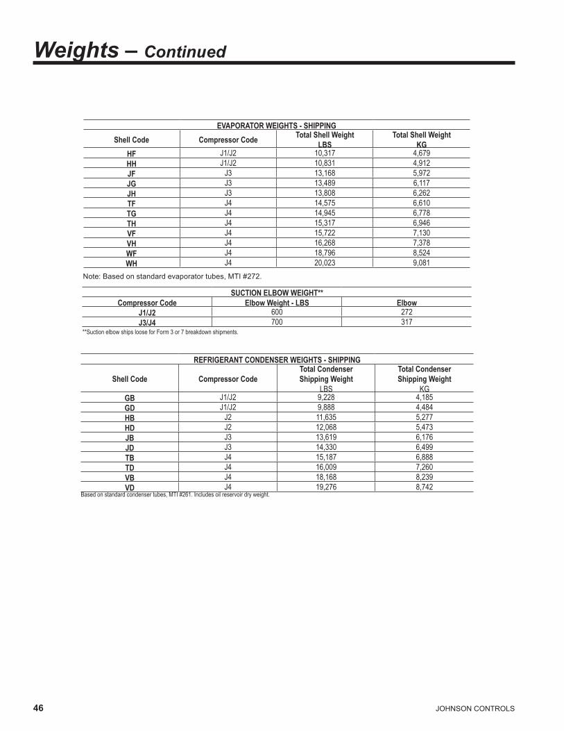
46 JOHNSONCONTROLS
Weights – Continued
EVAPORATOR WEIGHTS - SHIPPING Shell Code Compressor Code Total Shell Weight
LBS Total Shell Weight
KG HF J1/J2 10,317 4,679HH J1/J2 10,831 4,912JF J3 13,168 5,972JG J3 13,489 6,117JH J3 13,808 6,262TF J4 14,575 6,610TG J4 14,945 6,778TH J4 15,317 6,946VF J4 15,722 7,130VH J4 16,268 7,378WF J4 18,796 8,524WH J4 20,023 9,081
Note: Based on standard evaporator tubes, MTI #272.
SUCTION ELBOW WEIGHT** Compressor Code Elbow Weight - LBS Elbow
J1/J2 600 272J3/J4 700 317
**Suction elbow ships loose for Form 3 or 7 breakdown shipments.
REFRIGERANT CONDENSER WEIGHTS - SHIPPING
Shell Code Compressor Code Total Condenser Shipping Weight
LBS
Total Condenser Shipping Weight
KG GB J1/J2 9,228 4,185GD J1/J2 9,888 4,484HB J2 11,635 5,277HD J2 12,068 5,473JB J3 13,619 6,176JD J3 14,330 6,499TB J4 15,187 6,888TD J4 16,009 7,260VB J4 18,168 8,239VD J4 19,276 8,742
Based on standard condenser tubes, MTI #261. Includes oil reservoir dry weight.
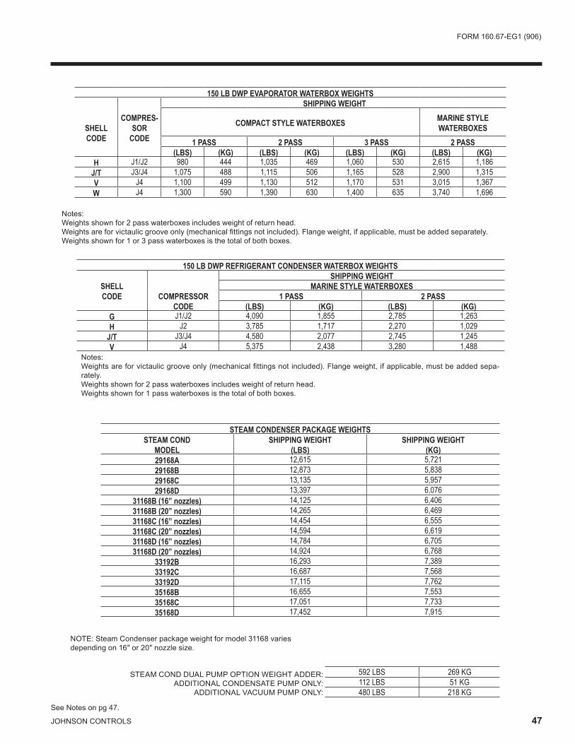
FORM160 .67-EG1(906)
JOHNSONCONTROLS 47
150 LB DWP EVAPORATOR WATERBOX WEIGHTS
SHELL CODE
COMPRES-SOR
CODE
SHIPPING WEIGHT
COMPACT STYLE WATERBOXES
MARINE STYLEWATERBOXES
1 PASS 2 PASS 3 PASS 2 PASS(LBS) (KG) (LBS) (KG) (LBS) (KG) (LBS) (KG)
H J1/J2 980 444 1,035 469 1,060 530 2,615 1,186J/T J3/J4 1,075 488 1,115 506 1,165 528 2,900 1,315V J4 1,100 499 1,130 512 1,170 531 3,015 1,367W J4 1,300 590 1,390 630 1,400 635 3,740 1,696
Notes:Weightsshownfor2passwaterboxesincludesweightofreturnhead .Weights are for victaulic groove only (mechanical fittings not included). Flange weight, if applicable, must be added separately.Weightsshownfor1or3passwaterboxesisthetotalofbothboxes .
150 LB DWP REFRIGERANT CONDENSER WATERBOX WEIGHTS
SHELL CODE
COMPRESSOR CODE
SHIPPING WEIGHT MARINE STYLE WATERBOXES
1 PASS 2 PASS (LBS) (KG) (LBS) (KG)
G J1/J2 4,090 1,855 2,785 1,263H J2 3,785 1,717 2,270 1,029
J/T J3/J4 4,580 2,077 2,745 1,245V J4 5,375 2,438 3,280 1,488
Notes:Weights are for victaulic groove only (mechanical fittings not included). Flange weight, if applicable, must be added sepa-rately .Weightsshownfor2passwaterboxesincludesweightofreturnhead .Weightsshownfor1passwaterboxesisthetotalofbothboxes .
STEAM CONDENSER PACKAGE WEIGHTS STEAM COND
MODEL SHIPPING WEIGHT
(LBS) SHIPPING WEIGHT
(KG) 29168A 12,615 5,72129168B 12,873 5,83829168C 13,135 5,95729168D 13,397 6,076
31168B (16” nozzles) 14,125 6,40631168B (20” nozzles) 14,265 6,46931168C (16” nozzles) 14,454 6,55531168C (20” nozzles) 14,594 6,61931168D (16” nozzles) 14,784 6,70531168D (20” nozzles) 14,924 6,768
33192B 16,293 7,38933192C 16,687 7,56833192D 17,115 7,76235168B 16,655 7,55335168C 17,051 7,73335168D 17,452 7,915
NOTE: Steam Condenser package weight for model 31168 variesdepending on 16" or 20" nozzle size.
592 LBS 269 KG 112 LBS 51 KG 480 LBS 218 KG
STEAM COND DUAL PUMP OPTION WEIGHT ADDER:ADDITIONAL CONDENSATE PUMP ONLY:
ADDITIONAL VACUUM PUMP ONLY:
SeeNotesonpg47 .
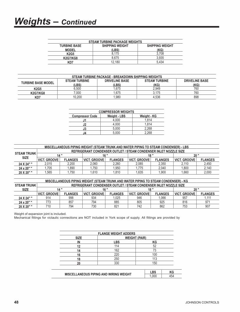
4� JOHNSONCONTROLS
STEAM TURBINE PACKAGE WEIGHTS TURBINE BASE
MODEL SHIPPING WEIGHT
(LBS) SHIPPING WEIGHT
(KG) K2G5 8,175 3,708
K2G7/KG8 8,675 3,935KD7 12,180 5,434
STEAM TURBINE PACKAGE - BREAKDOWN SHIPPING WEIGHTS TURBINE BASE MODEL STEAM TURBINE
(LBS) DRIVELINE BASE
(LBS) STEAM TURBINE
(KG) DRIVELINE BASE
(KG) K2G5 6,500 1,675 2,949 760
K2G7/KG8 7,000 1,675 3,175 760KD7 10,200 1,980 4,536 898
COMPRESSOR WEIGHTS Compressor Code Weight - LBS Weight - KG
J1 4,000 1,814J2 4,000 1,814J3 5,000 2,268J4 5,000 2,268
MISCELLANEOUS PIPING WEIGHT (STEAM TRUNK AND WATER PIPING TO STEAM CONDENSER) - LBS
STEAM TRUNK SIZE
REFRIGERANT CONDENSER OUTLET / STEAM CONDENSER INLET NOZZLE SIZE 14 " 16 " 18 " 20 "
VICT. GROOVE FLANGES VICT. GROOVE FLANGES VICT. GROOVE FLANGES VICT. GROOVE FLANGES 24 X 24" " 2,015 2,200 2,060 2,260 2,085 2,350 2,110 2,45024 x 20" " 1,705 1,890 1,750 1,950 1,775 2,040 1,800 2,14020 X 20" " 1,565 1,750 1,610 1,810 1,635 1,900 1,660 2,000
MISCELLANEOUS PIPING WEIGHT (STEAM TRUNK AND WATER PIPING TO STEAM CONDENSER) - KG
STEAM TRUNK SIZE
REFRIGERANT CONDENSER OUTLET / STEAM CONDENSER INLET NOZZLE SIZE 14 " 16 " 18 " 20 "
VICT. GROOVE FLANGES VICT. GROOVE FLANGES VICT. GROOVE FLANGES VICT. GROOVE FLANGES 24 X 24" " 914 998 934 1,025 946 1,066 957 1,11124 x 20" " 773 857 794 885 805 925 816 97120 X 20" " 710 794 730 821 742 862 753 907
Weightofexpansionjointisincluded .Mechanical fittings for victaulic connections are NOT included in York scope of supply. All fittings are provided by
FLANGE WEIGHT ADDERS SIZE WEIGHT (PAIR)
IN LBS KG 12 114 5214 162 7316 220 10018 250 11320 330 150
MISCELLANEOUS PIPING AND WIRING WEIGHT LBS KG 1,000 454
Weights – Continued

FORM160 .67-EG1(906)
JOHNSONCONTROLS 49
THERMAL INSULATION OPTION LBS KG 125 57
SHIPPING SKIDS LBS KG 400 181
SHELL PACKAGE OPERATING WEIGHT (ADDITIONAL WATER, REFRIGERANT AND OIL WEIGHT ONLY)
COMPR. SHELLS WATER WEIGHT REFRIGERANT WEIGHT OIL WEIGHT(LBS) (KG) (LBS) (KG) (LBS) (KG)
J1/J2 2,835 1,286 2625 1190
200 91
HFGD 3,095 1,404HHGB 3,065 1,390HHGD 3,325 1,508
J2 3,380 1,533 2825 1281HFHD 3,555 1,612
HHHB 3,615 1,639HHHD 3,785 1,717
J3
4,385 1,989 3495 1585JFJD 4,665 2,116JGJB 4,530 2,054JGJD 4,815 2,184JHJB 4,680 2,122JHJD 4,960 2,249
J4
5,010 2,272 3995 1812TFTD 5,330 2,417TGTB 5,180 2,349TGTD 5,500 2,494THTB 5,345 2,424THTD 5,670 2,571
J4 6,385
2,896 4150 1882VFVD 6,820 3,093VHVB 6,635 3,009VHVD 7,070 3,206
J4 7,050 3,197 4460 2023WFVD 7,490 3,397
WHVB 7,610 3,451WHVD 8,045 3,649
Water weights based on standard evaporator tube MTI #272 and standard condenser tube MTI #261.
150 LB DWP EVAPORATOR WATERBOX WEIGHTS
SHELL CODE
COMPRESSOR
CODE
OPERATING WEIGHT (ADDITIONAL WATER WEIGHT ONLY) COMPACT STYLE WATERBOXES
1, 2 OR 3 PASSMARINE STYLE WATERBOXES
2 PASS(LBS) (KG) (LBS) (KG)
H J1/J2 750 304 1,240 562J/T J3/J4 905 410 1,540 698V J4 1,020 463 1,800 816W J4 1,330 603 2,360 1,070
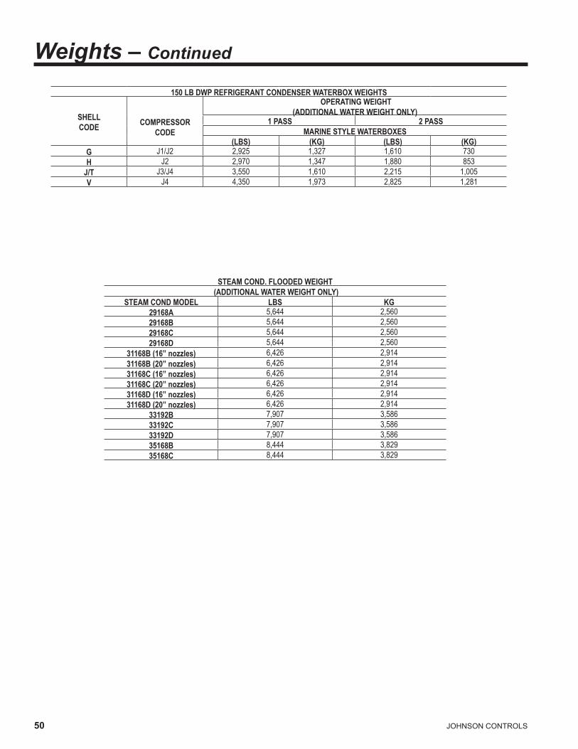
50 JOHNSONCONTROLS
150 LB DWP REFRIGERANT CONDENSER WATERBOX WEIGHTS
SHELL CODE
COMPRESSOR
CODE
OPERATING WEIGHT (ADDITIONAL WATER WEIGHT ONLY)
1 PASS 2 PASS MARINE STYLE WATERBOXES
(LBS) (KG) (LBS) (KG) G J1/J2 2,925 1,327 1,610 730H J2 2,970 1,347 1,880 853
J/T J3/J4 3,550 1,610 2,215 1,005V J4 4,350 1,973 2,825 1,281
STEAM COND. FLOODED WEIGHT (ADDITIONAL WATER WEIGHT ONLY)
STEAM COND MODEL LBS KG 29168A 5,644 2,56029168B 5,644 2,56029168C 5,644 2,56029168D 5,644 2,560
31168B (16” nozzles) 6,426 2,91431168B (20” nozzles) 6,426 2,91431168C (16” nozzles) 6,426 2,91431168C (20” nozzles) 6,426 2,91431168D (16” nozzles) 6,426 2,91431168D (20” nozzles) 6,426 2,914
33192B 7,907 3,58633192C 7,907 3,58633192D 7,907 3,58635168B 8,444 3,82935168C 8,444 3,829
Weights – Continued

FORM160 .67-EG1(906)
JOHNSONCONTROLS 51
Guide SpecificationsGENERALFurnishandinstallwhereindicatedonthedrawings____YORKYSTMaxECentrifugalLiquidChillingUnit(s) .Eachunit shall produce a capacity ____ of tonR, cooling ____ GPM of ____ from ____ °F to ____ °F when supplied with ____ GPM of condenser water at ____ °F. Steam consumption shall not exceed ____ lbs/hr with an IPLV (APLV) of ____. The evaporator shall be selected for____hrft2°F/BTU fouling factor and a maximum liquid pres-suredropof____ft .Watersideshallbedesignedfor___psig working pressure. The refrigerant condenser shall beselectedfor____hrft2°F/BTU fouling factor and the steamcondensershallhaveacleanlinessfactorof____ .Themaximumrefrigerantandsteamcondenserpressuredripshallbe____ft .Watersideshallbedesignedfor___psig working pressure. Steam shall be supplied to the turbine at ____ psig and ____ °F.
(or)
Furnish and install where indicated on the drawings___YORKYSTMaxECentrifugalLiquidChillingUnit(s) .Each unit shall produce a capacity of ____ kW, cool-ing ____ l/s of ____ from ____ °C to ____ °C when supplied with ____ l/s of condenser water at ____°C. Steam consumption shall not exceed ____ kg/hr with an IPLV (APLV) of ____. The evaporator shall be se-lected for ____ m2K/kW fouling factor and maximum liquid pressure drop of ____kPa. Waterside shall be designed for ___ barg working pressure. The refrig-erant condenser shall be selected for ____ m2K/kW fouling factor and the steam condenser shall have acleanliness factor of ____ . The maximum refrigerantand steam condenser pressure drop shall be ____kPa. Waterside shall be designed for ___ barg working pres-sure .Steamshallbesuppliedtotheturbineat____bargand ____ °C.
Each unit shall be factory-packaged including evaporator, refrigerant condenser, sub-cooler, compressor, steam turbine, lubrication system, Power Panel, Programmable ControlCenterandall inter-connectingunitpipingandwiring .Asteamcondensershallbeshippedseparatelyandwillbesuitableformountingontherefrigerantcon-denser. When specified, the steam condenser may be placed on the floor adjacent to the chiller (Customer to confirm which arrangement before the order is placed). Thechillershallbepaintedpriortoshipment .
The initial charge of oil and refrigerant shall be supplied, shipped in containers and cylinders for field installation orfactorychargedinthechiller .
POWER PANEL
All motor contactors and circuit protectors, the compres-soroilpumpvariablespeeddriveandthecontrolpowertransformershallbecontainedinanenclosureinstalledadjacent to theOptiViewcontrolcenter .Amainpowerdisconnectswitchshallbesuppliedwhichprovidestheterminationpointsforthecustomer’ssinglepointpowersupplywiring .
PROGRAMMABLE CONTROL CENTER
The Programmable Control Center shall be factory-mounted, wired and tested microprocessor based control system for R134a centrifugal chillers . The panel shallbe configured with a 10.4". diagonal color Liquid Crystal Display (LCD) surrounded by “soft” keys, which are rede-fined with one keystroke based on the screen displayed atthattime .
TheLCDdisplayshallprovideagraphicalandanimateddisplay of the chiller, chiller sub-systems and system pa-rameters, allowing the presentation of several operating parametersatonce .AStatusBarshallbedisplayedatalltimesonallscreenscontainingtheSystem-StatusLine and Details Line, the Control Source, Access Level, TimeandDate .
During turbine slow roll, startup, operation and coast-down, the system status shall indicate vital information availableatany time .Datashallbedisplayed ineitherEnglishorSIunits .
Securityaccessshallbeprovidedtopreventunauthor-izedchangesofsetpoints .Theremustbedifferentlevelsofaccessincludingaservicinglevelwhichshallprovidediagnosticsandtroubleshootinginformationforthechillerand panel. Password protection shall be provided for all accesslevels .
Thecontrolcenterpowersupplyisprovidedfromafused2KVAtransformerlocatedinthepowerpanel .
Thecontrolcenterisalsofusedtoprovideindividualover-current protectedpower for the remotemountedwaterpumpmotorstarters(suppliedbyothers)andthecontrolsinstalledonthechiller .Numberedterminalstripsforwir-ing such as Remote Start / Stop, Chilled Water Pump and LocalorRemoteCyclingdevicesshallbeprovided .ThePanel must also provide field interlocks that indicate the chillerstatus .ThesecontactsshallincludeaRemoteModeReady-to-Start, a Controlled Shutdown, a Safety Shutdown anda chillerRun contact . Systempressures shall be

52 JOHNSONCONTROLS
monitoredwithtransmitters(4-20mA)andtransducers(0-5VDC) .SystemtemperaturesshallbemonitoredusingthermistorsandRTD’s .
Setpointscanbechangeablefromaremotelocationvia0-10VDC and 4-20mA, contact closures or through se-rialcommunications .SerialdatainterfacetotheBuildingAutomationSystem(BAS)shallbethroughanoptionalMicrogatewayCardthatcanbemountedinsidetheCon-trolCenter .
The operating program shall be stored in non-volatilememorytoeliminatechillerfailureduetoACpowerfail-ure/battery discharge. Programmed setpoints shall be retained in lithium battery-backed RTC memory for 11 yearsminimum .
Control system shall allow the chiller to operate at 36°F (2.2°C) leaving chilled water temperature without nuisance tripsonlowwatertemperaturebymonitoringthechillerwaterandevaporatorrefrigerant liquidtemperaturestopreventfreezeup .
Everyprogrammablepointshallhaveapop-upscreenwith the allowable ranges, so that the chiller can not be programmedtooperateoutsideofitsdesignlimits .
Thecapacitycontrollogicshallprovidestableoperationat maximum efficiency at off design conditions by modu-lating the turbine speed, compressor pre-rotation vanes andhotgasby-passvalve .
When the power is applied to the chiller, the HOME screen shallbedisplayed . TheHOMEscreenshalldisplayavisual representation of the chiller and a collection ofdatadetailingimportantoperationsandparameters .Theprimaryvaluesthatneedtobemonitoredandcontrolledshallbeshownonthisscreen .
CAPACITY CONTROL
Thechillershallbedesigned tooperatewithcapacitiesfrom100%to10%ofdesigncapacity .
HOT GAS BY-PASS
The chiller shall be equipped with an external, hot gas by-passvalveprovidingoperationalcapabilityforpartloadsdownto10%ofdesign .Hotgasby-passvalveshallhaveanelectricactuatorandshallbeautomaticallycontrolledbythechillermicropaneltoopenonlywhenstablechilleroperationcannotbemaintainedthroughspeedreductionand PRV closure alone.
COMPRESSOR
Thecompressorshallbeasingle-stagecentrifugaltypedriven by a condensing steam turbine . The housingshall be fully accessible with vertical circular joints, with the complete operating assembly removable from thecompressor and scroll housing . Compressor castingsshall be designed for a minimum 200 psig (1379 kPa) working pressure and hydrostatically pressure tested at a minimum of 300 psig (2070 kPa). The rotor assembly shallconsistofaheat-treatedalloysteeldriveshaftandimpeller shaft with a cast aluminum, fully shrouded impel-ler. The impeller shall be designed for balanced thrust, dynamically balanced and overspeed tested for smooth, vibration-freeoperation . Insert-type journaland thrustbearings shall be fabricated of aluminum alloy, precision boredandaxiallygrooved .
Internalsinglehelicalgearswithcrownedteethshallbedesignedsothatmorethanonetoothisincontactatalltimestoprovideevenloaddistributionandquietoperation .Eachgearshallbeindividuallymountedinitsownjournalandthrustbearingstoisolateitfromimpellerandturbineforces. Shaft seal shall be provided in double bellows, double-seal, cartridge type. Capacity control shall be achievedbyuseofpre-rotationvanesandspeedcontroltoprovidefullymodulatingcontrolfromfullloadtomini-mum load for maximum energy efficiency. Control shall automaticallycompensateforadverseoperatingcondi-tions, such as fouled tubes, and adjust to prior operation aftercorrectionoftheseconditions .The unit shall be capable of continuous, reliable operation withlowECWTatallloadconditionsasoutlinedontheequipment schedule. An external, electric actuator shall automaticallycontrolpre-rotationvaneposition .
COMPRESSOR LUBRICATION SYSTEM
Lubricationoilshallbeforce-fedtoallcompressorbear-ings, gears, and rotating surfaces by an external variable speed oil pump. The oil pump shall vary oil flow to the compressor based on operating and stand-by conditions, ensuringadequatelubricationatalltimes .Theoilpumpshall operate prior to start-up, during compressor opera-tionandduringcoastdown .Compressorshallhaveaninternal, auxiliary reservoir at the top of the compressor housingtoprovidegravity fed lubricationduringcoast-downintheeventofapowerfailure .
An oil reservoir, separate from the compressor, shall contain the submersible 2 HP oil pump and a 3000 watt oil heater, thermostatically controlled to remove refriger-antfromtheoil .
Oil shall be filtered by an externally mounted 1/2 micron re-
Guide Specifications - Contin-

FORM160 .67-EG1(906)
JOHNSONCONTROLS 53
placeable cartridge oil filter equipped with service valves. Oil shall be cooled via a shell and tube, water cooled oil coolersizedtouserefrigerantenteringcondenserwater .TheoilsideoftheoilcoolershallbeprovidedwithservicevalvesandanAmotthreewaytemperaturecontrolvalve .Oilpipingshallbecompletelyfactory-installed .Thewaterside of the oil cooler shall be provided with service valves, inlet strainer and solenoid valve for automatic start/stop of cooling water flow. Water piping shall be factory installed with connections brought to the edge of the chiller pack-ageandclearlytaggedforinstallation .Anautomaticoilreturnsystemshallbeprovided to recoveranyoil thatmayhavemigratedtotheevaporator .
STEAM TURBINE DRIVELINESteam Turbine Package
The steam turbine shall be of a high efficiency multistage designoperatingatanominal4500rpmdesignmaxi-mumspeed .
The turbine shall be packaged on a driveline base, com-pletely factorypiped . Thedrivelinebaseshallhaveamating flange on shaft end of the package that will bolt directly to the compressor D-flange face providing a rigid interface between turbine package and compressor. Complete turbine/compressor driveline shall be factory aligned prior to shipment . Turbine drive shaft shall bedirectly connected to the compressor shaft with a flexible disccoupling .Couplingshallhaveallmetalconstructionwith no wearing parts to assure long life, and no lubrica-tionrequirementstoprovidelowmaintenance .
The turbinecasingshall behorizontally split designedto allow longitudinal thermal expansion without affect-ing alignment or efficiency of the turbine. The shaft and wheels shall be alloy steel with the wheels shrunk and keyed to the shaft. The turbine blades shall be of 403gradestainlesssteelandtheshaftshallbegroundthroughoutwithstainlesssteelsprayedinthecarbonringendglandcontactarea .Stainlesssteelnozzlesshallbefurnishedthroughouttheturbine .Carbonringendglandanddiaphragmsealsshallbefurnished .Turbineendglandcarbon ring seals (minimum five seals per end gland) shall beseparatedbypartitionsofstainlesssteel .
A stainless steel, inlet steam strainer with adequate size andmeshtominimizethepressuredropshallbesupplied .Strainer shall be removable without breaking the steam pipingconnections .
A fiberglass insulating blanket shall be provided on the steamchestandbarreloftheturbineforoperatorpro-tection .
Theturbinespeedcontrolshallbeachievedbyagover-norvalvethatisintegratedwiththechillercontrols .The
valveshallbeofstainlesssteelwithstainlesssteelseatsand designed to control flow throughout the entire oper-atingrangeoftheturbine .Thesystemshallemployanoverspeedgovernordesignedtoclosean independenthigh performance butterfly trip valve with a pneumatic actuatorwhentheturbinespeedexceeds110percentofthemaximumcontinuousoperatingspeedoftheturbine .Activationoftheindependenttripvalveshallcausethegovernor valve toalso close . Amicro switch shall befurnished on the trip linkage for the customer’s use.
TURBINE LUBRICATION SYSTEMS
RingOil LubricatedTurbines -Drivepowers less than1700Hp (1268 kW) onlyThe bearings shall be steel backed, babbitt lined, split sleevetype .Thedesignshallbesuchthatthebottomhalf is removablewith theshaft inplace . Thebearinghousingshallhaveprovisionsforairpurgingofthehousingshaftseals .Thethrustbearingshallbeanantifrictionballbearing, accessible and removable without lifting the top halfoftheturbinecasing .Oilcoolingwithwatercooledbearinghousingsshallbeprovided .
External, Pressurized Lube System TurbinesThe bearings shall be steel backed, babbitt lined, split sleevetype .Thedesignshallbesuchthatthebottomhalf is removablewith theshaft inplace . Thebearinghousingshallhaveprovisionsforairpurgingofthehousingshaft seals. The thrust bearing shall be a double acting, Kingsburytype .Thelubricationsystemshallbeintegraltotheturbinedrivelinebaseandcompletelyfactorypiped .The lubrication system shall consist of a turbine shaftdriven main oil pump, motor driven auxiliary oil pump, water cooled shell and tube oil cooler, 25 micron full flow oil filter and separate oil reservoir with level gauge. Oil temperaturecontrolshallbebyAmotthreewaytempera-turecontrolvalve .
STEAM CONDENSER PACKAGE
Asteamcondensershallbeprovidedtocondenseexhauststeam at vacuum pressures to maintain efficient turbine operation . The steam condenser water circuit shall bepiped in series with the refrigerant condenser, eliminating aseparatecoolingwatercircuitandshallbedesignedtominimizepressuredropforenergysavings .
The steam condenser shall be furnished fully packaged. The package shall include a single 5 HP hotwell pump, a single 7.5 HP liquid ring vacuum pump for air removal, atmosphericreliefvalveandlevelcontrolsystem .Thepackage shall be factory piped, wired and mounted on acommonstructuralsteelframesuitableforinstallationon the refrigerant condenser or floor mounting adjacent
54 JOHNSONCONTROLS
tothechillersystem .
Steam condenser construction shall be of the shelland tube type of welded steel construction with 3/4" OD (19 mm) prime surface copper tubes, roller-expanded into tubesheets .Watersideshallbesuitableforamaximumworking pressure of 150 psig (1030 kPa). Steam side shall be designed for 15 psig (100 kPa) and 30" Hg vac (760 mmHg) .Waterboxesshallbeweldedsteelwithremov-ablecovers .Condensatelevelshallbecontrolledbyalevelcontrolsystemwithtwo(2)pneumaticcontrolvalves-oneforre-circulationandtheotherforremovalofcon-densate .Theliquidringvacuumpumpshallbecapableofdrawingthecondenserdowntooperatingpressureinapproximately10minutes .Hotwellpumpshallbesingle-stage, end suction suitable for hotwell service.
Atmosphericreliefvalveshallbeawatersealtypewithexter-nal handwheel, sized in accordance with the Heat Exchange InstituteStandards(HEI)forprotectionofthesteamturbineexhaust, steam trunk and steam condenser.
All key control and monitoring parameters shall be integral to the chiller control panel. In addition, auxiliary pressure gaugesshallbelocatedatthecondensersteaminletandcondensate pump discharge piping, and temperature gauges shall be located at the steam inlet, cooling water inlet and outlet, and the hotwell.
To facilitate rigging, condenser shall be separable from the skid by unbolting. Insofar as practical, piping shall be outfitted with unions at reasonable break-points. Both condenser and skid shall be outfitted with lifting lugs for bothverticalandhorizontallifting .
EVAPORATOREvaporator shall be of the shell-and-tube, flooded type designed for a minimum of 180 psig (1241 kPa); working pressureontherefrigerantside .Shellshallbefabricatedfrom rolled carbon steel plates with fusion weldedseams, carbon steel tube sheets, drilled and reamed to accommodate the tubes, and intermediate tube supports spaced no more than four feet apart . The refrigerantside of each shell is designed, tested and stamped in accordance with ASME Boiler and Pressure Vessel Code, Section VIII - Division I, or other pressure vessel code asappropriate .
Heat exchanger tubes shall be high-efficiency, externally and internally enhanced type. Tubes shall utilize the “skip-fin” design, providing a smooth internal and external surfaceateachintermediatetubesupport .Thisprovidesextra wall thickness and non-work hardened copper at the support location, extending the life of the heat exchangers.
If skip-fin tubes are not used, minimum tube wall thick-ness shall be 0.035" (0.889 mm). Each tube shall be roller expanded into the tube sheets providing a leak-proof seal, andbeindividuallyreplaceable .Watervelocitythroughthetubes shall not exceed 12 ft./sec. (3.7 m/s). A liquid level sightglassshallbeprovidedonthesideoftheshelltoaid in determining proper refrigerant charge and to check condition of the refrigerant charge. A suction baffle or aluminummesheliminatorsshallbe locatedabovethetubebundletopreventliquidrefrigerantcarryovertothecompressor .TheevaporatorshallhavearefrigerantreliefdevicesizedtomeettherequirementsoftheASHRAE15SafetyCodeforMechanicalRefrigeration .Waterboxesshallberemovabletopermittubecleaningand replacement . Stub-out water connections havingVictaulicgroovesshallbeprovided .
Water boxes shall be designed for 150 psig (1030 kPa) design working pressure and be tested at 225 psig (1550 kPa). Vent and drain connections with plugs shall be pro-videdoneachwaterbox .
(Option)Thewaterboxesshallbesuitablefor300psig(2070 kPa) and be tested at 450 psig (3103 kPa). Vent anddrainconnectionswithplugsshallbeprovidedoneachwaterbox .
REFRIGERANT CONDENSER
Refrigerant condenser shall be of the shell-and-tube type, designed for a minimum of 235 psig (1620 kPa) working pressure on the refrigerant side . Shell shall be fabri-catedfromrolledcarbonsteelplateswithfusionweldedseams. Carbon steel tube sheets, drilled and reamed to accommodate the tubes, are welded to the end of each shell .Intermediatetubesupportsaredrilledandreamedto eliminate sharp edges, fabricated from carbon steel plates. The refrigerant side of each shell is designed, testedandstampedinaccordancewithASMEBoilerandPressure Vessel Code, Section VIII - Division I, or other pressurevesselcodeasappropriate .
Heat exchanger tubes shall be high efficiency, externally and internally enhanced type. Tubes shall utilize the “skip-fin” design, providing a smooth internal and external surfaceateachintermediatetubesupport .Thisprovidesextra wall thickness and non-work hardened copper at the support location, extending the life of the heat exchang-ers. If skip-fin tubes are not used, minimum tube wall thickness shall be 0.035" (0.889 mm). Each tube shall be roller expanded into the tube sheets providing a leak-proof seal, and be individually replaceable. Water velocity through the tubes shall not exceed 12 ft/sec (3.7 m/s). A liquidlevelsightglassshallbeprovidedonthesideofthe
Guide Specifications - Continued
FORM160 .67-EG1(906)
JOHNSONCONTROLS 55
shelltoaidindeterminingproperrefrigerantchargeandto check condition of the refrigerant charge. The refriger-ant condenser shall have dual refrigerant relief devices; eachsizedtomeettherequirementsoftheASHRAE15SafetyCodeforMechanicalRefrigeration .Arrangementshallalloweithervalvetobeisolatedandreplacedwithoutremovingtheunitrefrigerantcharge .
(Option)Therefrigerantcondensershallbeprovidedwithpositiveshutoffvalvesinthecompressordischargelineandintheliquidlineleavingthecondenser .Thiswillallowpumpdownandstorageoftherefrigerantchargeintherefrigerantcondenser .
Waterboxes shall be removable topermit tubeclean-ingandreplacement .StuboutwaterconnectionshavingVictaulicgroovesshall beprovided .Waterboxesshallbe designed for 150 psig (1030 kPa) design working pressure and be tested at 225 psig (1550 kPa). Vent and drainconnectionswithplugsshallbeprovidedoneachwaterbox .
REFRIGERANT FLOW CONTROL
A variable orifice valve shall control refrigerant flow to the evaporator .Thisvalvecontrolshallautomaticallyadjusttomaintainproperrefrigerantlevelintherefrigerantcon-
denserandshallbecontrolledbymonitoringrefrigerantliquid level, assuring optimal subcooler performance.
PORTABLE REFRIGERANT STORAGE RECYCLING SYSTEM
A portable, self-contained refrigerant storage / recycling systemshallbeprovidedconsistingofarefrigerantcom-pressor with oil separator, storage receiver, water-cooled condenser, filter drier and necessary valves and hoses to remove, replace and distill refrigerant. All necessary controlsandsafetydevicesshallbeapermanentpartofthesystem .
START-UP AND OPERATOR TRAINING
Thechillermanufacturershallincludetheservicesofafactory-trained, field service representative to supervise the final leak testing, charging and the initial startup and concurrentoperatorinstruction .

SI Metric Conversion
MEASUREMENT MULTIPLY THIS BY TO OBTAIN THIS ENGLISH VALUE METRIC VALUE
CAPACITY TONS REFRIGERANT EFFECT (ton) 3.516 KILOWATTS (kW) POWER KILOWATTS (kW) NO CHANGE KILOWATTS (kW) HORSEPOWER (hp) 0.7457 KILOWATTS (kW) FLOW RATE GALLONS / MINUTE (gpm) 0.0631 LITERS / SECOND (L/s) LENGTH FEET(ft) 304 .8 MILLIMETERS(mm) INCHES(in) 25 .4 MILLIMETERS(mm) WEIGHT POUNDS (lb) 0.4536 KILOGRAMS (kg) VELOCITY FEET / SECOND (fps) 0.3048 METERS / SECOND (m/s)
PRESSURE DROP FEET OF WATER (ft) 2.989 KILOPASCALS (k Pa) POUNDS / SQ. INCH (psi) 6.895 KILOPASCALS (k Pa)
Values provided in this manual are in the English inch-pound (I-P) system. ThefollowingfactorscanbeusedtoconvertfromEnglishtothemostcommonSlMetricvalues .
TEMPERATURE
To convert degrees Fahrenheit (°F) to degrees Celsius (°C), subtract 32° and multiply by 5/9 or 0.5556.
To convert a temperature range (i.e., 10°F or 12°F chilled water range) from Fahrenheit to Celsius, multiply by 5/9 or0 .5556 .
EFFICIENCY
In the English l-P system, chiller efficiency is measured in kW / ton:
kW / ton = kW input tonsrefrigeranteffect
In the Sl Metric system, chiller efficiency is measured in Coefficient of Performance (COP).
COP = kW refrigeration effect kW input
kW / ton and COP are related as follows:
kW/ton = 3 .516 COP
COP = 3 .516 kW/ton
FOULING FACTOR
ENGLISH l-P EQUIVALENT Sl METRIC (fl2 °F hr/Btu) (m2 k/kW)
0 .0001 .018 0 .00025 .044 0 .0005 .088 0 .00075 .132
For Steam systems (I-P system):
COP = Refrigeration effect (Btu/hr) Steam flow (lb/hr) x (Steam supply (Btu/lb) - condensate return (Btu/lb))
ForSteamsystems(SIsystem):
COP = Refrigeration effect (kW) Steam flow (kg/s) x (Steam supply (kJ/kg) - condensate return (kJ/kg))
�������������������������������������������������� �������������������������������
������������������������������������������������������������������������
Form160 .67-EG1(905)Supersedes:160 .67-EG1(205)FileinET4