model Ypc Paraflow Two-stage Direct-fired Absorption Chiller · Model YPC ParaFlow Two-Stage...
36
Model YPC ParaFlow Two-Stage Direct-Fired Absorption Chiller-Heaters Style A Models YPC‑DF‑12SC through YPC‑DF‑19S 200 through 675 Tons 703 kW through 2372 kW FORM 155.17‑EG4 (1108)
Transcript of model Ypc Paraflow Two-stage Direct-fired Absorption Chiller · Model YPC ParaFlow Two-Stage...
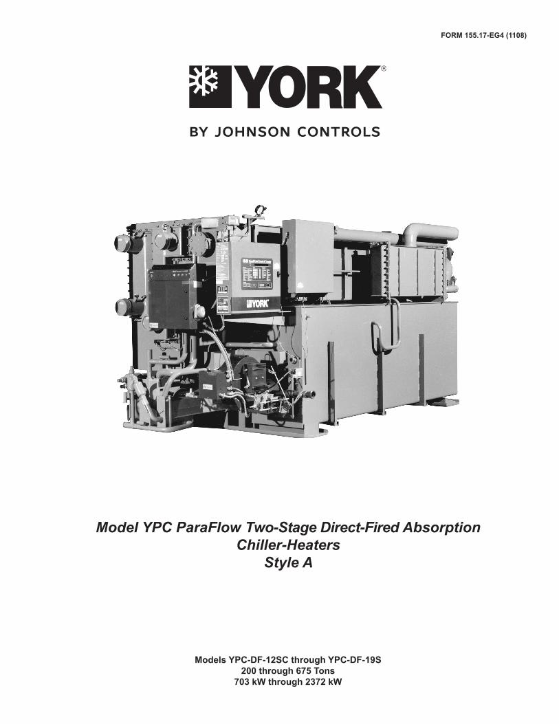
Model YPC ParaFlow Two-Stage Direct-Fired Absorption Chiller-Heaters
Style A
Models YPC‑DF‑12SC through YPC‑DF‑19S200 through 675 Tons
703 kW through 2372 kW
FORM 155.17‑EG4 (1108)

JOHNSON CONTROLS�
NOMENCLATURE
The model number denotes the following characteristics of the unit:
Model Tube Code
Heat Source Heater Code
Size Code Electrical Code
YPC - FN - 14SC - 46 - H - A
Table of ContentsFORM 155.17-EG4 (1108) ..................................................................................................................................................................................... 1Introduction ........................................................................................................................................................................................................... 3How It Works ........................................................................................................................................................................................................ 4Ratings .................................................................................................................................................................................................................. 8MicroComputer Control Center ........................................................................................................................................................................... 9Mechanical Specifications ..................................................................................................................................................................................11Application Data ................................................................................................................................................................................................. 15Dimensions ......................................................................................................................................................................................................... 24Electrical Data ..................................................................................................................................................................................................... 26Nozzle Arrangements: 12SC - 14SC ................................................................................................................................................................. 28Nozzle Arrangements: 15SL and Larger........................................................................................................................................................... 29Guide Specifications .......................................................................................................................................................................................... 30

FORM 155.17‑EG4 (1108)
�JOHNSON CONTROLS
YPC ParaFlow Two-Stage Direct-Fired Absorption Chiller-HeatersStyle A
The YORK ParaFlow YPC Direct-Fired Absorption Chiller offers an environmentally-friendly alternative to electric energy. Since a YPC Direct-Fired Chiller uses inexpensive natural gas rather than electricity, owners can balance their energy needs and take advantage of the competi-tion in an open energy market. And, because the unit also provides hot water for heating, typical applications will not require a boiler – saving even more money. With today’s energy and environmental considerations, the YPC Direct-Fired Absorption Chiller is the ideal choice for a wide range of applications.
U.S. made YPC Direct-Fired Chillers come equipped with the same sophisticated microprocessor controls found throughout Johnson Controls’ product lines, making the YPC Direct-Fired Chiller the smartest absorber on today’s market.
With its high efficiency, “Smart Controls,” proven reliability and the guaranteed quality of a standard performance test, U.S. made units are the ideal choice for today’s demand-ing specifications.
Introduction

JOHNSON CONTROLS4
CHILLING CYCLE
YPC’s remarkably efficient two‑stage absorption refrig-eration cycle uses water as the refrigerant and lithium bromide as the absorbent. It is the strong affinity these two substances have for each other that makes the cycle work. The entire process occurs in hermetic vessels in an almost complete vacuum.
The large diagram above indicates the complete chilling cycle. The six steps are detailed here and on the next page, with corresponding numbers in the diagram to show where each step takes place. YPC’s two-stage absorption chilling cycle is continuous; however, for the sake of clarity and simplicity, it is divided into six steps.
1. Solution Pump/Heat Exchangers
A dilute solution of lithium bromide and water descends from the Absorber to the Solution Pump. This flow of dilute solution is split into two streams and pumped through
How It Works
heat exchangers to the First-Stage Generator and to the Second-Stage Generator.YPC’s exclusive two‑way split of solution flow virtually eliminates the possibility of crystallization (solidification) by allowing the unit to operate at much lower solution con-centration and temperatures than series flow systems.
2. First‑Stage Generator
A heat source heats dilute lithium bromide coming from the Solution Pump/Heat Exchangers. This produces hot refrigerant vapor which is sent to the Second-Stage Gen-erator, leaving a concentrated solution that is returned to the Heat Exchangers.
3. Second‑Stage GeneratorThe energy source for the production of refrigerant vapor in the Second-Stage Generator is the hot refrigerant vapor produced by the First-Stage Generator.
CHILLING CYCLE

FORM 155.17‑EG4 (1108)
�JOHNSON CONTROLS
This is the heart of Johnson Controls’ remarkably efficient two-stage absorption effect. The refrigerant vapor pro-duced in the First-Stage Generator is increased by 40% – at no additional expense of fuel. The result is much higher efficiency than in conventional systems.
This additional refrigerant vapor is produced when dilute solution from the Heat Exchanger is heated by refriger-ant vapor from the First-Stage Generator. The additional concentrated solution that results is returned to the Heat Exchanger. The refrigerant vapor from the First-Stage Generator condenses into liquid giving up its heat, and continues to the Condenser.
4. CondenserRefrigerant from two sources – (1) liquid resulting from the condensing of vapor produced in the First-Stage Genera-tor and (2) vapor produced by the Second‑Stage Genera-tor – enters the Condenser. As the liquid refrigerant enters the low pressure of the condenser it flashes to vapor. The two sources of refrigerant vapor combine and condense to liquid as they are cooled by the condenser water. The liquid then flows down to the Evaporator.
5. EvaporatorRefrigerant liquid from the Condenser passes through a metering valve and flows down to the Refrigerant Pump, where it is pumped up to the top of the Evaporator. Here the liquid is sprayed out as a fine mist over the Evaporator
tubes. Due to the extreme vacuum (6 mm Hg) in the Evapo-rator, some of the refrigerant liquid vaporizes, creating the refrigerant effect. (This vacuum is created by hydroscopic action – the strong affinity lithium bromide has for water – in the Absorber directly below.)
The refrigerant effect cools the returning system chilled water in the Evaporator tubes. The refrigerant liquid/vapor picks up the heat of the returning chilled water, cooling it from 54°F to 44°F (12.2°C to 6.6°C). The chilled water is then supplied back to the system.
6. AbsorberAs the refrigerant liquid/vapor descends to the Absorber from the Evaporator, a concentrated solution coming from the Heat Exchanger is sprayed out into the flow of descending refrigerant. The hydroscopic action between lithium bromide and water-and the related changes in concentration and temperature-result in the creation of an extreme vacuum in the Evaporator directly above. The dissolving of the lithium bromide in water gives off heat, which is removed by condenser water entering from the cooling tower at 85°F (29.4°C) and leaving for the Condenser at 92°F (33.3°C). The resultant dilute lithium bromide solution collects in the bottom of the Ab-sorber, where it flows down to the Solution Pump.
The chilling cycle is now completed and begins again at Step 1.
Note: There are two heat exchangers, but only one is shown for illustrative purposes.

JOHNSON CONTROLS6
HEATING CYCLE WITHOUT HOT WATER HEAT ExCHANGER
1. First‑Stage GeneratorAn energy source heats dilute lithium bromide solution in the First-Stage generator. This produces hot refrigerant vapor which travels through the open valve VD and also moves through the Second-Stage generator and Con-denser to the evaporator.
2. EvaporatorThe hot refrigerant vapor travels through the evapora-tor where it gives up heat to the system hot water, and changes state from vapor to liquid as its heat is removed. The refrigerant liquid collects in the bottom of the evapo-rator.
3. Refrigerant PumpThe refrigerant pump removes the refrigerant liquid from the evaporator and pumps it into the second stage gen-erator where it mixes with intermediate lithium bromide solution to form dilute lithium bromide solution.
4. Heat Exchangers/AbsorberThe dilute lithium bromide flows to the solution heat ex-changer where it combines with the concentrated solu-tion from the First Stage generator to form intermediate solution. The intermediate solution then flows through the absorber.
5. Solution Pump/Heat ExchangersThe solution pump moves the intermediate solution from the absorber through the solution heat exchangers and into the first and second stage generators and the process begins again.
HEATING CYCLE WITHOUT HOT WATER HEAT ExCHANGER
How It Works - continued

FORM 155.17‑EG4 (1108)
�JOHNSON CONTROLS
HEATING CYCLE WITH OPTIONAL HOT WATER HEAT ExCHANGER
1. First‑Stage GeneratorDilute lithium bromide solution is heated by the energy source in the First-Stage Generator. This drives off refrig-erant vapor and leaves concentrated solution.
2. Hot Water Heat ExchangerThe hot refrigerant vapor from the first stage generator gives up its heat to the System Hot Water Heat Exchanger and condenses to liquid as the heat is removed. The condensed refrigerant liquid returns to the First-Stage Generator and the cycle begins again.
HEATING CYCLE WITH OPTIONAL HOT WATER HEAT ExCHANGER

JOHNSON CONTROLS�
COMPUTERIzED PERFORMANCE RATINGS
Each chiller selection is custom-matched to meet the individual application requirements. It is not practical to provide tabulated information for all possible combina-tions. Computerized performance ratings are available through each Johnson Controls Sales Office.
Ratings
* Shows the part load performance of the YORK ParaFlow YPC chiller‑heater. The highest efficiency is achieved between 50 and 100 percent chilling capacity. Valid for leaving chilled water temperature 42°‑ 52°F (6.6°C ‑ 12.2°C).
Fig. 1 details the high efficiency part load performance of the YPC Absorption Chiller. At both constant tower water temperatures and ARI adjusted entering tower tem-peratures, the unique ParaFlow design delivers superior economy at low loads.
FIG. 1 – ENERGY INPUT VS. OUTPUT*
TABLE 1 – IPLV ANALYSIS**
** IPLV (expressed as a COP) = 1.10
LOAD (%) COP
°F °C
100 85.0 29.4 1.00 0.17 0.17
75 78.8 26.0 1.10 0.39 0.43
50 72.5 22.6 1.17 0.33 0.39
25 68.0 20.0 1.09 0.11 0.12
ENTERING COND. WATER TEMP.
WEIGHTING
FACTOR (FROM ARI 560-92)
WEIGHTED AVERAGE COP
FORM 155.17‑EG4 (1108)
�JOHNSON CONTROLS
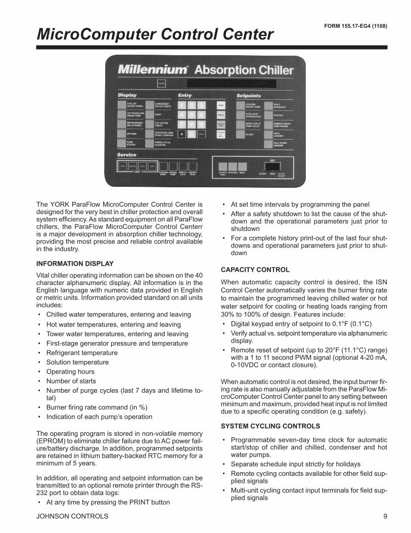
MicroComputer Control Center
The YORK ParaFlow MicroComputer Control Center is designed for the very best in chiller protection and overall system efficiency. As standard equipment on all ParaFlow chillers, the ParaFlow MicroComputer Control Centerr is a major development in absorption chiller technology, providing the most precise and reliable control available in the industry.
INFORMATION DISPLAY
Vital chiller operating information can be shown on the 40 character alphanumeric display. All information is in the English language with numeric data provided in English or metric units. Information provided standard on all units includes: • Chilled water temperatures, entering and leaving • Hot water temperatures, entering and leaving • Tower water temperatures, entering and leaving • First-stage generator pressure and temperature • Refrigerant temperature • Solution temperature • Operating hours • Number of starts • Number of purge cycles (last � days and lifetime to-
tal) • Burner firing rate command (in %) • Indication of each pump’s operation
The operating program is stored in non-volatile memory (EPROM) to eliminate chiller failure due to AC power fail-ure/battery discharge. In addition, programmed setpoints are retained in lithium battery-backed RTC memory for a minimum of � years.
In addition, all operating and setpoint information can be transmitted to an optional remote printer through the RS-��� port to obtain data logs: • At any time by pressing the PRINT button
• At set time intervals by programming the panel • After a safety shutdown to list the cause of the shut-
down and the operational parameters just prior to shutdown
• For a complete history print-out of the last four shut-downs and operational parameters just prior to shut-down
CAPACITY CONTROL
When automatic capacity control is desired, the ISN Control Center automatically varies the burner firing rate to maintain the programmed leaving chilled water or hot water setpoint for cooling or heating loads ranging from �0% to 100% of design. Features include: • Digital keypad entry of setpoint to 0.1°F (0.1°C) • Verify actual vs. setpoint temperature via alphanumeric
display. • Remote reset of setpoint (up to 20°F (11.1°C) range)
with a 1 to 11 second PWM signal (optional 4-�0 mA, 0‑10VDC or contact closure).
When automatic control is not desired, the input burner fir-ing rate is also manually adjustable from the ParaFlow Mi-croComputer Control Center panel to any setting between minimum and maximum, provided heat input is not limited due to a specific operating condition (e.g. safety).
SYSTEM CYCLING CONTROLS
• Programmable seven-day time clock for automatic start/stop of chiller and chilled, condenser and hot water pumps.
• Separate schedule input strictly for holidays • Remote cycling contacts available for other field sup-
plied signals • Multi‑unit cycling contact input terminals for field sup-
plied signals

JOHNSON CONTROLS10
WARNING CONDITIONS/INHIBITED UNIT LOADING
The ParaFlow MicroComputer Control Center provides a warning display message and, when beneficial to the machine, will limit heat input to �0% or 60% when operat-ing conditions indicate the unit is moving towards a safety shutdown. This gives the operator the opportunity to fix a problem before it leads to a complete safety shutdown. Warnings include the following: • Low refrigerant temperature • High generator pressure or temperature • High or low entering condenser water temperature • Purge pump current overload • Faulty solution dilution temperature sensor
SHUTDOWN CONTROLS
The following conditions will lead to unit shutdown. After a shutdown, the reason for the shutdown is displayed in English on the alphanumeric display. Each annunciation details the day, time, reason for shutdown and the type of restart required.
Cycling – those controls which automatically reset and permit auto restart of the system. • Loss of condenser water flow • Low leaving chilled water temperature • Power failure (when automatic restart is selected)Safety – those controls which (when employed) require
a manual operation to restart the system. • Solution pump thermal or current overload • Refrigerant pump thermal or current overload • Low refrigerant temperature • First stage generator high temperature or pressure • First stage generator low solution level • Burner alarm indication • Burner Panel malfunction (combustion-related mal-
function) • Loss of chilled water flow • Power failure (when automatic restart not used) • Incomplete dilution cycle due to any of the following: • Power failure • Solution/refrigerant pump overloads • Low refrigerant temperature • Loss of chilled water flow • Auxiliary safety shutdown terminals for field supplied
signals
CONCENTRATION CALCULATOR
The micropanel monitors the first‑stage generator concen-tration to prevent operation at an unsafe concentration. Concentration is tied into both the Warning Conditions and Safety Shutdown systems discussed in this section. Also
included is an operator interface concentration calcula-tor. When in the Program mode, an operator can use the concentration calculator to determine concentration by inputting set of conditions. The operator must input any two of three parameters (bromide solution temperature, saturation temperature, and pressure) and the micropanel will display the concentration. The display will also indicate if the input conditions are in the crystallization zone.Control Mode Selection
The ParaFlow MicroComputer Control Center includes secure programming and servicing capabilities. There are three keys for the selection of the control center modes:
• ACCESS CODE permits access to the control center PROGRAM button when the proper password is given
• PROGRAM permits operator to program the setpoints and select desired MODE:
• LOCAL allows manual unit start and purging. • REMOTE allows remote start and stop of the unit
remote reset of the chilled water temperature limit, while still allowing manual purging at the chiller.
• SERVICE allows manual operation of the burner firing rate, including LOAD, UNLOAD, HOLD, and AUTO keys. Manual operation of all pumps is also included.
ENERGY MANAGEMENT INTERFACE
By connecting with the YORK Integrated Systems Network, the ParaFlow MicroComputer Control Center can communicate all data accessible from the keypad (including all temperatures, pressures, alarms and oper-ating data) to a remote DDC processor through a single shielded cable. In remote mode, the DDC processor may issue all operating commands available at the keypad to the control center through the same shielded cable. With an ISN translator panel, other BAS systems can receive this same information.
The ParaFlow MicroComputer Control Center also pro-vides a direct hard wire interface capability with other building automation systems using a 1-11 PWM standard signal (4‑20 mA, 0‑10VDC or contact closure optional) including the following: • Remote unit start/stop • Remote chilled water temperature reset • Remote hot water temperature reset • Remote read out of status including: • Unit ready to start • Unit operating • Unit safety shutdown • Unit cycling shutdown

FORM 155.17‑EG4 (1108)
11JOHNSON CONTROLS
Mechanical SpecificationsGENERAL
The YORK ParaFlow YPC Direct-Fired Absorption Liquid Chiller-Heater is completely factory-packaged, including a first‑stage (high temperature) generator, burner, burner panel, solution heat exchangers, main shell, hot water heater, microprocessor controls and all interconnecting unit piping and wiring.
All models are shipped as a single piece complete with al factory balanced LiBr and refrigerant charge inside of the unit to simplify and expedite start up. The unit is also shipped with a nitrogen charge to eliminate the possibility of air entering the machine during shipment. Burner and Burner panel on each unit are factory mounted, wired and tested and ship preinstalled as integral components of the Chiller-Heater.
The purchase price includes the services of a Johnson Controls factory‑trained, field service representative to supervise the initial start-up of the machine.
SOLUTION FLOW
The solution flow is divided into two parallel paths, one leading to the first stage generator and one to the second stage generator. In this way, each stream is concentrated only once, allowing for a more safe and efficient operation. The balance of flow between the two streams is pre‑set at the factory and fine‑tuned at start up to ensure maximum efficiency for any given application.
MAIN SHELL
The main shell consists of four separate shell and tube heat exchangers – the absorber, evaporator, condenser and second stage (low temperature) generator – all housed in a single carbon steel shell divided into low pressure and intermediate pressure sections. The shell is fabricated from formed carbon steel plates with fusion welded seams. Carbon steel tube sheets, drilled and reamed to accommodate the tubes, are welded to the end of the shell. Intermediate tube supports are fabricated of carbon steel plates. Each tube is roller expanded into the tube sheets to provide a leak tight seal; each tube is individually replaceable. The solution side of the shell is designed for a working pressure of 60 mm Hg absolute.The portion of the shell opposite the burner houses the low pressure section of the machine which includes the evaporator and the absorber. Both the absorber and the evaporator are drip‑type heat exchangers with 5/8” (16 mm) OD, .025” (0.6 mm) wall copper tubing for the 12SC‑14SC, and 3/4” (19 mm) OD, 0.028” (0.7 mm) wall for the 1�SL and larger. Tubes are externally enhanced where necessary to achieve desired capacity. The absorber and evaporator are separated by finned eliminator baffles designed to allow water in the vapor state to pass to the absorber.
The burner side of the shell contains the intermediate pressure section of the machine consisting of the con-denser and second stage generator. The second stage generator is a drip‑type heat exchanger with 5/8” (16 mm), .025” (0.635 mm) wall, copper tubing for the 12SC‑14SC, and 3/4” (19 mm) OD, .028” (0.7 mm) wall for the 15SL and larger. Generator and condenser are separated by baffling which prevents liquid carryover to the condenser. Condenser tubing is 5/8” (16 mm), .025” (0.635 mm) wall copper tubing for the 12SC‑14SC, and 3/4” (19 mm) OD, .028” (0.7 mm) wall for the 15SL and larger.
The removable compact water boxes are fabricated of steel. The design working pressure is 150 PSIG (1 MPa) and the boxes are tested at 225 PSIG (1.6 MPa). Integral steel water baffles are located and welded within the water box to provide the required pass arrangements. Stub-out water nozzles connections with ANSI/AWWA C-606 grooves are welded to the water boxes. These nozzles are suitable for ANSI/AWWA C-606 couplings, welding or flanges, and are capped for shipment. Plugged vent and drain connections and lifting lugs are provided on each water box.
FIRST STAGE GENERATOR
The first stage generator is a single flooded heat ex-changer using vertical carbon steel boiler tubes. The shell side is fabricated from carbon steel plate with fusion welded seams, and is designed for a working pressure of 13.5 PSIA (93 kPa). The unit bursting disk is designed to fail at 12 PSIG (83 kPa). Carbon steel eliminator baffles prevent solution carryover over with the refrigerant va-por. The generator uses a series of bare and enhanced vertically-oriented, carbon-steel boiler tubes to enhance heat transfer. Hot combustion gases flow from the com-bustion chamber across the tubes to provide the neces-sary heat input.
The high temperature generator contains a solution float valve which controls the level of solution in the genera-tor. This limits the amount of sensible heating at part load conditions, resulting in much better performance.
SOLUTION HEAT ExCHANGER
The solution heat exchanger is a shell and tube design with geometrically‑enhanced 5/8” (16 mm) OD for the 12SC‑14SC, and 0.578” (15 mm) OD for the 15SL and larger, �0/10 cupro-nickel tubing. The shell is formed from carbon steel plate with fusion welded seam. Tubes are roller expanded into carbon steel tube sheets. BURNER
The burner is a forced draft, flame retention burner listed by Underwriters Laboratories (IRI, FM and other codesavailable as options) and capable of operating on natu-ral gas, propane, or No. 2 oil (as specified by the cus-tomer).

JOHNSON CONTROLS1�
The burner is made of welded steel and the combusion-head incorporates a multi‑blade stainless steel, flame retention diffuser. Minimum turndown ratio is � to 1.
Combustion air is supplied by an integrally-mounted blower assembly incorporating a direct-drive, �-phase motor. The burner uses a full-modulation-type fuel/air control system.
The gas control train is prepiped and prewired with suit-able junction boxes and terminal strips to burner panel terminal connections. The gas train contains the following components: manual shutoff cock, main gas pressure regulator, low and high gas pressure switches, two (2) UL listed leak test cocks, burner manifold gas pressure gauge, two (2) main motorized gas valves (for gas inputs of 5.0 MMBTU/HR and lower), two (2) main motorized gas valves – one (1) with proof of closure interlock switch (for gas inputs above 5.0 MMBTU/HR), and one (1) normally open vent valve sized according to IRI requirements.
The oil control train (when specified) incorporates U.L. approved components supplied by the burner manufac-turer to provide the specified fuel/air control operation. The system uses a single high pressure oil nozzle of the internal-bypass type. The nozzle oil train includes one (1) 300 lb. (2.1 MPa) gauge to read nozzle return oil pressures.
The high pressure nozzle supply oil pump is a two (2) gear type capable of producing 300 PSIG (2.1 MPa) dis-charge pressure and 15 inches (381 mm) Hg. vacuum. It is a separate unit mounted on its own support base with a direct drive motor. The oil pump unit comes complete with removable mesh-type oil strainer, 0-�00 PSIG (�.1 MPa) oil nozzle pressure gauge, nozzle line, main and auxiliary solenoid safety shutoff oil valves and low oil pressure switch. The oil nozzle bypass line uses dual check valves.
The flame safeguard control includes fully automatic pre-purge and post-purge sequencing of the burner blower motor, interrupted ignition system, and fuel/air flow com-ponents with an ultraviolet sensor for flame detection.
PUMPS
Solution and refrigerant pumps are hermetically sealed, self-lubricating, totally enclosed, liquid cooled, facto-ry-mounted, wired and tested. Motor windings are not exposed to LiBr or water. The suction and discharge connections for each pump are fully welded to the unit piping to minimize the opportunity for leaks. Suction and discharge connections are also equipped with factory installed isolation valves to permit quick and easy servic-ing of pumps. AII YPC units include one or two solution pump(s) and a refrigerant pump. Pumps are designed to operate for a total of ��,000 hours between service inspections.
VALVES
All valves used for adjusting the solution are fully welded or brazed to prevent leakage of air into the unit. Valve actuators are covered with a seal cap to eliminate the possibility of air leakage through the stem. Additionally, all connections of valves to unit piping are fully welded.
SOLUTION AND REFRIGERANT
Each ParaFlow unit is charged with lithium bromide solution with non-toxic lithium molybdate as a corrosion inhibitor. Refrigerant is deionized water. A small amount of �-ethyl hexanol is added as a heat and mass transfer enhancer.
PURGE SYSTEM
The purge system automatically and constantly removes noncondensible vapors generated in the absorption pro-cess through the use of an eductor. Noncondensibles are then stored in a purge chamber until they can be removed through the use of a purge pump. The purge pump is an oil, rotary, two-stage vacuum pump with a 1/4 HP, �-Phase, ODP motor.
The chiller control panel includes a SmartPurge system that will automatically sense the amount of non-conden-sibles in the purge chamber and empty the tank whenever necessary. The SmartPurge system eliminates the need for an operator to ever manually empty the purge cham-ber. In addition, the control panel monitors the frequency of purge cycles and alerts the chiller operator, through a unique control panel warning message, if the number if purges exceeds normal levels.
CAPACITY CONTROL
Capacity control is accomplished by modulating the burner’s firing rate. The YPC Direct‑Fired unit is capable of modulating capacity from �0% to 100%.
The two‑stage chiller design incorporates a float valve that limits solution flow to the generator as the cooling load decreases. This maintains optimum solution level through-out the operating range. In addition, manual control valves are used by Johnson Controls technicians in the factory and/or at start‑up to fine tune solution and refrigerant flows to match the jobsite needs at peak efficiency.
POWER PANEL
The power panel enclosure includes the following: single point wiring connection for the incoming power supply; non-fused disconnect switch; motor starters, complete with current and thermal-overload protection for solution pump(s), refrigerant pump, and purge pump (current overloads only); 115VAC 50/60 Hz control power trans-former.
Mechanical Specifications - continued

FORM 155.17‑EG4 (1108)
1�JOHNSON CONTROLS
PARAFLOW MICROCOMPUTER CONTROL CENTER
The microprocessor based control center is factory-mount-ed, wired and tested. The electronic panel automatically controls the operation of the unit in meeting system cooling or heating requirements while minimizing energy usage. Chiller operating parameters are sensed by either therm-istors or transducers and displayed on the keypad. All pressures are taken as absolute to alleviate typical gauge pressure inaccuracies. Temperatures and pressures can be displayed in English (F, PSIA) or metric (C, KPa) units depending on the application. Display of all information is shown in the English language on a 40-character al-phanumeric display.
Available operating information includes return/leaving chilled water temperatures, return/leaving tower water temperatures, first stage generator pressure and tem-perature, refrigerant and solution temperatures, operat-ing hours, burner firing rate and number of starts and purges.
Warning Conditions – The ParaFlow MicroComputer Control Center provides a warning annunciation and, when appropriate, limits heat input under the following conditions: low refrigerant temperature, high generator pressure or temperature, high or low entering condenser water temperature, purge pump current overload, faulty solution dilution temperature sensor.
Safety Controls – The control center includes unique safety logic designed to protect the YPC chiller from damaging malfunctions. Complete safety annunciation is displayed for each shut-down by pressing the status key. This information includes day, time and reason for shutdown. These include: solution- or refrigerant-pump thermal or current overload, low refrigerant temperature, first‑stage generator high pressure or temperature, loss of chilled water flow, power failure, burner safety shut-down, auxiliary safety shutdown, incomplete dilution cycle and power failure if manual restart after power failure is selected.
Operating Controls – Background messages are displayed while the unit is running to signal operator of controlling conditions such as leaving chilled water tem-perature control and non-critical sensor error. System cycling messages display day, time, cause of cycling shutdown, and autostart indication. These include loss of condenser water (or hot water) flow, low‑leaving chilled water (or high leaving hot water) temperature, and power failure (when autostart is selected).
Digital programming of operating setpoints from the key-pad include leaving chilled water (or hot water) tempera-ture, pulldown demand limiting, remote reset temperature range daily start/stop scheduling of chiller and water
pumps with separate holiday schedule.
Security access code is provided for operator to program setpoints or to choose local, remote, or service modes of operation. Manual control of the burner firing rate and all pumps is provided through separate buttons in the service mode of operation.
Data Logging – All operating and setpoint information can be transmitted to a remote printer (by others) through the RS-��� port in the control center to obtain data logs. This can be accomplished at any time by pressing the “Print” button on the control center, or automatically at predetermined intervals by programming the panel’s data logger. The printer will automatically record time and cause of any safety or cycling shutdown along with all chiller operating data monitored by the panel just prior to shutdown. A “History Print” button also allows the printout of the last four causes of cycling or safety shutdowns plus operating data for each shutdown.
BAS Interface – The ParaFlow MicroComputer Control Center is compatible with remote Building Automation Sys-tems (BAS). The standard design allows remote start and stop; leaving chilled-water temperature reset and steam demand limit through PWM signal; and “ready‑to‑start,” “unit running”, “safety” and “cycling” shutdown status contacts. For designed-in features and reliability, Johnson Controls provides a full line of BAS controls.
FACTORY LEAk TEST
Each ParaFlow unit is subjected to a series of four rigorous leak tests, culminating in a vacuum leak test measured by a mass spectrometer and conducted while the unit is immersed in an atmosphere of low-density helium.Codes and Standards • CSD-1 • U.L. (other codes as an option for burner/gas train
system) • ARI �60-�� NEC - National Electrical Code • OSHA – Occupational Safety and Health Act Paint
Exterior surfaces are protected by an initial coat of red oxide primer with a single finish coat of Caribbean‑blue, air-drying, high-solids, enamel machinery paint.
SHIPMENT
Protective covering is furnished on the microprocessor controls, burner and other electric devices. Water nozzles are capped prior to shipment.

JOHNSON CONTROLS14
SPECIAL TUBE MATERIALS AND WALL THICk‑NESSES
YPC units are designed for long life with the standard tube materials and wall thicknesses in each heat exchanger. For special applications where different tube specifications are required, Johnson Controls offers copper tubing with .028” (0.71 mm) (where .025” (0.635 mm) is standard) and .035” (0.89 mm) wall thicknesses. Also, 90/10 cupro‑nickel tubes are available for the absorber, evaporator, and con-denser in both the standard and the above-listed optional tube-wall thickness.
WATER FLANGES
150 lb. (68 kg) ANSI raised‑faced flanges for the evapora-tor and/or absorber/condenser water connection are fac-tory welded to water nozzles. Companion flanges, bolts, nuts and gaskets are not included.
WATER FLOW SWITCH
This is a paddle‑type, vapor‑proof water flow switch suitable for 150 PSIG (1.0 MPa) DWP (300 PSIG [2.1 MPa] available) for the absorber/condenser water circuit (chilled‑water flow switch is standard).
SPARE PUMPS
A complete set of replacement solution and refrigerant pumps ships alongside the unit for local spare parts inventory.
REMOTE RESET CONTROLS
An optional board allows for continuous reset of leaving chilled-water temperature using a 4 to �0 mA, O to 10 VDC, or contact closure as opposed to the standard 1 to 11 second PWM signal. These signals may be wired directly to the panel terminal block on the card file without any external interfacing.
SHIP WITH SEPARATE CHARGE
All models ship with the LiBr and refrigerant charge in the unit. For applications which require light rigging loads, the charge can be removed and shipped alongside the unit for recharging in the field.
LOW NOx BURNER
For areas with restrictive clean air requirements, Johnson Controls offers a burner with low (<30 ppm) nitrous oxide emissions.
SPECIAL BURNER CODES
Many localities have their own code requirements for equipment with burners. When specified, Johnson Con-trols can provide a burner built to meet special code requirements.
175°F HOT WATER OPTION
This option includes an external heater which allows up to 175°F (79.4°C) leaving hot water temperature, and allows simultaneous heating and cooling (See Figs. 3 and 4).
MARINE WATER BOxES
Marine water boxes allow service access for cleaning of the heat exchanger tubes without the need to break the water piping. Bolted-on covers are arranged for conve-nient access.Victaulic nozzle connections are standard; flanges are optional. Marine water boxes are available for the evaporator or the absorber/condenser circuits. Marine water boxes are only available for circuits with 1�0 PSIG (1.0 MPa) working pressures.
HIGH PRESSURE WATER CIRCUITS
For applications with working pressures which exceed 1�0 PSIG (1.0 MPa), high pressure water boxes are available. These compact water boxes are rated for �00 PSIG (�.1 MPa) DWP and tested at 450 PSIG (3.1 MPa).
OPTIONAL FEATURES

FORM 155.17‑EG4 (1108)
1�JOHNSON CONTROLS
The following discussion is a user guide in the application and installation of ParaFlow YPC Chiller-Heaters to ensure the reliable, trouble-free life for which this equipment was designed. While this guide is directed towards normal water-chilling applications, your local Johnson Controls sales representative can provide complete recommenda-tions on other types of applications.
LOCATION
YPC units make very little noise or vibration and may generally be located at any level in a building where the construction will support the total system operating weight. The unit site should be a floor, mounting pad or foundation which is level and capable of supporting the operating weight of the chiller. The unit will operate properly and produce maximum output only if it is installed level within 1/1000 of unit length in the lengthwise direction and 1/1000 of unit width in the widthwise direction.
Leave between 46 and 60 inches (1.17 ‑ 1.52 m) of space around the machine for servicing, reading instruments, and performing tests. If there are flammable materials near the machine, leave at least 20 inches (0.5 m) of space above the machine and at least 40 inches (1.02 m) above the first stage generator. Required tube pull space is equal to the unit length on either end of the machine, with 40 inches (1.02 m)on the opposite end.
Absorption chillers are not suitable for outdoor installa-tion. The machine room must be enclosed and properly ventilated to keep its temperature no higher than 104°F (40°C), and no lower than 35°F (1.7°C).
WATER CIRCUITS
Flow rate – For normal water chilling duty, chilled and tower water flows are permitted at any velocity between 4.9 and 10 fps (1.5 and 3.05 m/s). YPC chillers are de-signed for constant flow systems. Applications involving chilled and condenser water flow rates which vary by more than +/- 10% from design will require special consider-ation. Contact your Johnson Controls representative for flow limits at specific design conditions.
Temperature ranges – For normal chilling duty, leav-ing chilled water temperatures may be selected between 42°F and 60°F (5.55°C and 15.5°C) for water temperature ranges between 8°F and 20°F (4.4°C and 11.1°C).
Water quality – The practical and economical applica-tion of liquid chillers requires that the quality of the water supply for the evaporator and the absorber/condenser be analyzed by a water-treatment specialist. Water quality may affect the performance of any chiller through corro-sion, depositions of heat-resistant scale, sedimentation or organic growth. These will hurt chiller performance and
increase operating and maintenance costs. Normally, performance may be maintained by corrective water treat-ment and periodic cleaning of tubes. If water conditions exist which cannot be corrected by proper water treatment, it may be necessary to provide a larger allowance for foul-ing, and/or specify special materials of construction.
General water piping – All chilled water and tower water piping should be designed and installed in accordance with accepted piping practice. Chilled water and tower water pumps should be located to discharge through the unit to assure positive pressure and flow through the unit. Piping should include offsets to provide flexibility and should be arranged to prevent drainage of water from the evaporator and condenser when the pumps are shut down. Piping should be adequately supported and braced independent of the chiller to avoid imposition of strain on chiller components. Hangers must allow for alignment of the pipe. Isolators in the piping and in the hangers are highly desirable in achieving sound and vibration control.
Convenience considerations – With a view to facilitat-ing the performance of routine maintenance work, some or all of the following steps may be taken by the purchaser. Evaporator and condenser water boxes are equipped with plugged vent and drain connections. If desired, vent and drain valves may be installed with or without piping to an open drain. Pressure gauges with stop cocks, and stop valves, may be installed in the inlets and outlets of the tower and chilled water lines as close as possible to the chiller. An overhead monorail crane or beam may be used to facilitate servicing.
Connections – The standard unit is designed for 1�0 PSIG (1.0 MPa) design working pressure in both the chilled and tower water circuits. The connections (water nozzles) to these circuits are furnished with grooves for Victaulic couplings (ANSI flanges are optional). Piping should be arranged for ease of disassembly at the unit for performance of such routine maintenance as tube cleaning. A crossover pipe to route the tower water from the absorber into the condenser is integral to the machine construction for the 1�SC-14SC. Models 1�SL and larger require an external crossover pipe from absorber to con-denser. External crossovers are provided by Johnson Controls and will ship mounted on the chiller. All water piping should be thoroughly cleaned of all dirt and debris before final connections are made to the machine.
Pump on/off control - Contacts are provided in the ParaFlow MicroComputer Control Center to start/stop chilled and tower water pumps. The contacts can be used to supply 11�V power to a pump motor starter relay, or as dry contacts to signal a building automation system to start/stop flow through the chiller. Johnson Controls
Application Data

JOHNSON CONTROLS16
recommends that these contacts be used for all installa-tions whether they directly control the pumps or they are used as inputs that tell the building automation system when to supply flow. Absorption chillers require flow at shutdown to perform a dilution cycle that will vary in length depending on operating conditions at shutdown. Without flow, the dilution cycle will terminate early, which can lead to crystallization.
Chilled water – The chilled water circuit should be de-signed for constant flow. A flow switch, provided standard with the unit, must be installed in the chilled water line of every unit. The switch must be located in the horizontal piping close to the unit, where the straight horizontal runs on each side of the flow switch are at least five pipe diameters in length. The switch must be electrically con-nected to the chilled water interlock position in the unit control center. A water strainer, of maximum 1/8” mesh should be field‑installed in the chilled water inlet line as close as possible to the chiller. If located close enough to the chiller, the chilled water pump may be protected by the same strainer. The flow switch and strainer assure chilled water flow during unit operation. The loss or severe reduction of water flow could seriously impair performance or even result in tube freezeup.
Condenser water – Like the chilled water circuit, the tower water circuit requires a means of proving flow. The recommended method of proving flow is a tower water flow switch (not in standard supply scope, but available from Johnson Controls) installed in the tower water pip-ing in the same manner as the chilled‑water flow switch (above).
The YPC Chiller is engineered for maximum efficiency at both design and part load operation by taking advantage of the colder cooling tower water temperatures which naturally occur in the winter months. In its standard con-figuration, YPC absorbers can tolerate entering tower water temperatures as low as 68°F (20°C). Because the unit flow rates must be maintained, the recommended method of tower water temperature control is a three-way mixing valve.
At the initial startup, entering tower water temperature may be as low as 59°F (15°C), provided the water temperature rises to 68°F (20°C) within twenty minutes.
ON/OFF CYCLING
Once the chiller reaches its minimum operating load, if the cooling load decreases, the leaving chilled water temperature will fall below the setpoint. When the leaving chilled water temperature falls �°F below the setpoint, the chiller will cycle off. During a cycling shutdown, the
Control Center continues to monitor the leaving chilled water temperature; when the temperature rises 1°F above the setpoint, the chiller will cycle on. The on/off cycling band used causes no noticeable effect for most cooling applications. To prevent wear damage associated with starting and stopping, it is recommended that installations be designed to prevent the two-stage absorption chiller from cycling more than twice per hour.
RUPTURE DISk PIPING
All YPC Chillers ship with a rupture disk(s) designed to fail at 12 PSIG (0.83 bar). The purpose of the rupture disk is to quickly relieve excess pressure as a precaution in the event of an emergency such as a fire. Refer to factory submittal for rupture disk size.
A CPVC or fiberglass discharge pipe should run from the rupture disk to a drain. Steel rupture disk piping is not rec-ommended unless extra care is taken to support the piping and isolate any stress from the rupture disk.The discharge piping must supported independent of the unit.
SOUND AND VIBRATION CONSIDERATIONS
Since the unit generates very little vibration, vibration elimi-nating mounts are not usually required. However, when the machine is installed where even mild noise is a problem, mounts or pads can be used. The use of anchoring bolts on the machine legs is not normally necessary.
THERMAL INSULATION
YPC units require thermal insulation (by others) on both hot and cold surfaces in order to achieve maximum ef-ficiency and prevent sweating. Required insulation area is tabulated on p. ��.
SIMULTANEOUS OPERATION
YPC Chiller-Heaters equipped with an optional hotwater heat exchanger can provide both chilled water and hot water simultaneously. An understanding of the simulta-neous operation feature and its limitations is required to ensure proper application. Simultaneous operation can take place only if there is a basic demand for chilled water and when an optional high temperature heater is provided. The chillers operation of the machine during simultaneous operation is initiated and controlled by the chilling load, and it is essentially the same as the nor-mal chilling operation. The only difference is that during simultaneous operation some of the vapor generated in the first‑stage generator is utilized to make hot water. To control the hot water temperature, a motorized mixing valve and two temperature controllers must be supplied and installed in the hot water circuit by the installer as
Application Data - continued

FORM 155.17‑EG4 (1108)
1�JOHNSON CONTROLS
FIG. 3 – SIMULTANEOUS OPERATION
FIG. 4 – SUGGESTED PIPING SCHEMATIC FOR SIMULTANEOUS OPERATION (All piping and Controls by Others)

JOHNSON CONTROLS1�
FIG. 5 – HEATING MODE – STANDARD HEATER (TWO PIPE SYSTEM)
FIG. 6 – TYPICAL NOISE LEVELS
LD0161�
LD01616
NOISE LEVEL *Location 1 82 dB(A)Location 2 81 dB(A)Location 3 83 dB(A)Location 4 83 dB(A)
* Measured 1 meter from the machine
Application Data - continued

FORM 155.17‑EG4 (1108)
1�JOHNSON CONTROLS
shown in the sketch in Fig. 4. One controller senses the leaving hot water temperature and positions the mixing valve to maintain that temperature. The other controller acts as a limit switch and will abort simultaneous opera-tion by placing the mixing valve in the full by-pass position and stopping the hot-water circulating pump if the leaving chilled-water temperature rises to a pre-set level (usually 50°F (10°C)), indicating that too much energy is being used to make hot water and the chiller cannot meet the chilling demand.
Since the machine operation is controlled by the chilling load, the amount of available heating capacity as well as the hot water temperature will vary as the chilling load varies. The graph in Fig. � shows the relationship between chilling capacity and heating capacity at varying energy input rates.
For example, at 100% energy input rate (top curve), the machine will produce 100% chilling and no heating or, �0% chilling and �0% heating, or �0% chilling and 4�% heating, etc. At �0% energy input rate, the machine will produce �0% of the rated chilling capacity and no heating, or �0% chilling and approximately ��% heating, etc.
WARNING – When the YPC Chiller/Heater is in the heating only (not simultaneous) mode, the mixing valve must be in the open position to allow full flow through the hot water heat exchanger. The hot water controller will then modulate the burner to meet load variations and the machine will operate in the normal manner.
A standard heater is designed for a two pipe system, thus simultaneous is not possible. Heating is accomplished in the evaporator (See Fig. 5).
AIR SUPPLY AND CHIMNEY SYSTEM
Air Supply – As with any natural gas or No. 2 Oil‑fired appliance, adequate combustion air supply must be pro-vided for proper and complete combustion. As a general rule, 12 standard cubic feet (0.34 standard cubic meters) of air are required for every 1000 Btu (1054 kJ) of fuel burned, assuming combustion with �0% excess air.
In addition to direct combustion air, outside air is also needed for ventilation and as make up to any machine room air which is induced up the chimney through a baro-metric draft regulator.
Air supply openings of adequate size must be provided to the machine room in accordance with local codes and standards. The specific location and size should be suf-ficient to allow an unobstructed flow of fresh air to the burner. Under no circumstances should the static pres-sure in the mechanical room become negative (below atmospheric pressure).
Contacts are provided in the burner panel (supplied mounted on the YORK chiller‑heater) to tie in the open-ing and closing of fresh air dampers into the start/stop sequence of the chiller. If the fresh air dampers do not open within 60 seconds, the ParaFlow MicroComputer Control Center will shut the chiller down, preventing an unsafe operating condition.
Chimney Draft Theory – Draft control serves two im-portant functions for YPC Direct Fired chiller-heaters: 1. It removes the combustion products from the living or work space, and �. Minimizes excess draft which pulls useful heat out of the unit and lowers its efficiency.
Draft depends on two important factors: 1. The tempera-ture difference between the flue gas and the outside air, and �. The height of the chimney. Higher temperature differences between the flue gas and the outside air, and higher chimneys both create more draft.
Chimney draft is the force created by the difference in temperature between the flue gases and the outside am-bient air. The magnitude of this temperature difference is directly proportional to the draft created. Temperature dif-ference causes draft because gases, such as air, occupy different volumes at different temperatures. For example: One cubic foot of air weighs 0.0834 pounds (37.8 grams) at a temperature of 0°F. This same cubic foot of air at 450°F (232°C) weighs only 0.0422 Ibs. (19.1 grams). The amount of mass per specific volume is referred to as density. Density decreases as temperature increases and lighter (lower density) air rises while heavier, more dense air sinks. This is the same phenomena that leads to air stratification in buildings. The temperature in a room at the thermostat may be 70°F (21.1°C) but the temperature near the ceiling may be 80°F (26.7°C).
Heated combustion gases being less dense than the cooler outside air rise and flow out of the top of the chimney and create a partial vacuum. This causes a negative pressure at the chimney inlet that pulls in more gas for venting. This pulling force is referred to as chimney draft.
Because the direct‑fired chiller‑heaters are capable of op-erating in both the heating and cooling modes, the outdoor air temperatures will change significantly from the summer (cooling season) to the winter (heating season). These wide temperature swings must be accounted for during system design. The larger the temperature difference the greater the draft. Therefore, when the unit is operating during the colder months more draft will be produced. It is essential that the chimney system be designed using summer ambient conditions so as to avoid undersizing the draft system.

JOHNSON CONTROLS�0
Chimney Design Theory – The following is a discus-sion of the basic terms and approach used in chimney design. It is not the intent of this section to address the fine details of proper chimney design. Because of the large number of variables, this must be addressed on an application specific basis by an experienced designer knowledgeable in chimney systems, draft control, and local code requirements.
Theoretical Draft (Dt) – The definition of Theoretical Draft is the natural draft or “Chimney Effect” produced by difference in densities of hot exhaust gas relative to cooler ambient air.
Available Draft (Da) – The Available Draft is the draft required at the outlet exhaust flange of the YORK High Temperature Generator.
Pressure Drop (dP) – Frictional losses in the chimney system which act against theoretical draft. The chimney draft needed to overcome chimney frictional losses is described as follows:
Dt = dP + Da
Proper chimney design balances the theoretical draft (Dt) against the pressure drop (dP) of the chimney system in order to provide the required available pressure(Da) at the outlet of the chiller-heater.
Proper chimney design must provide the required (Da) under all operating conditions. Because the difference between summer and winter ambient conditions can result in Dt variations of �0% and greater, some method of draft control is usually required in order to maintain Da.
Chimney Application – The YORK ParaFlow YPC direct‑fired chillerheater is equipped with a forced draft burner capable of firing on a variety of fuels, including natural gas and/or No. � oil and/or propane. As such, the unit will require a properly designed chimney system to control draft and discharge flue gases from the unit to the atmosphere.
The combustion chamber of the chiller-heater is engi-neered to product a positive gauge pressure of 0.0� to 0.15 in. of water (1.27 ‑ 3.81 kg/m2) at the outlet of the first stage generator with an exhaust temperature of 400°F+/‑50°F (204°C +/‑ 28°C). As such the chimney de-sign must provide a method for maintaining the pressure at all ambient conditions. Because YORK chiller-heaters operate at “high fire” throughout the summer months, it is important to design the chimney system for summer ambient design conditions to avoid undersizing. It is rec-ommended that the chimney itself should be designed for a Da of 0 (zero) in. (0 mm) of water column. This will
prevent the chimney from becoming pressurized at any point along the flue gas path.
Caution – If the stack/chimney pressure is ever above 0 (zero) in. of water column there is a chance of flue gas being leaked into the equipment room.
There are two commonly used ways to maintain the pres-sure at the outlet of the chiller-heater. Either manual or automatic/motorized draft control can be used. All YORK direct-fired chiller-heaters will come standard with a manual draft control damper. This damper can be modified for motorized operation either in the factory (if ordered) or in the field if site conditions require.
Manual Draft Control – Manual draft control is suitable for applications where each gas fired appliance will have its own dedicated chimney and draft control system. Fig. � depicts a simple yet effective means of controlling draft. With this system, a (field supplied) barometric draft regu-lator is used in series with the factory supplied manual backdraft damper. With maximum economy employed in the chimney design, Dt would exactly equal dP + Da during the summer design ambient conditions with the barometric regulator closed. In reality, some degree of conservatism should exist in the design, causing the barometric regula-tor to be open slightly even during summer design condi-tions. As ambient temperatures drop, Dt would increase, if not for the barometric draft regulator. With the regulator in place, mechanical room air is introduced into the chimney system in response to the impressed draft, thus stabiliz-ing the gauge pressure just upstream of the barometric regulator. Most barometric regulators can maintain -0.06 in. water column gauge pressure when properly sized for a particular application.
With the gauge pressure stabilized upstream of the baro-metric regulator, the factory supplied manual backdraft damper can be adjusted to a fixed position which will provide the pressure drop to yield the required positive pressure at the exhaust flange of the chiller‑heater.
Motorized Draft Control – Motorized draft control is suitable for applications where multiple gas fired appli-ances will be ducted into one common chimney system. In this case each unit will require its own draft control system. (Motorized draft control may be used for one chil-ler-heater/one chimney applications as well if it is desired over manual control.) Fig. 8 depicts a sequential draft control system which incorporates a motorized damper whose position is automatically adjusted as a function of available draft at the outlet of the chiller. The Johnson Controls supplied backdraft damper at the outlet of the chiller can be modified (in the factory if ordered, or in the field) to mount the motor driver. The motor is controlled from a draft control panel which senses the pressure at
Application Data - continued
FORM 155.17‑EG4 (1108)
�1JOHNSON CONTROLS
the outlet of the chiller-heater. The draft control panel is available from Johnson Controls to ship with the chiller. The panel is wired to the burner panel and damper motor in the field, and the pressure is sensed through a small line field connected to the outlet of the chiller‑heater.Special Problems and Maintenance – Factors causing draft variations during normal operation include: wind and weather factors, inadequate chimney construction or system installation, location of installation, or inadequate system maintenance.
Wind and weather – Windy conditions will tend to increase the draft in the chimney as the wind helps to remove the combustion products leaving the chimney at a much faster rate. Down draft may occur causing a temporary positive pressure in the chimney system. The stack should be designed to prevent not only wind, but rain and snow from entering the stack. A flue cap should be installed.
Inadequate System Installation – If the diameters of the chimney system are too restrictive, the combustion products and flue gases may not be allowed to leave the system. On the other hand if the flue passages are too large, the chimney is never given a chance to completely warm due to the large surface area of the flue. This situa-tion may cause poor draft and flue gas condensation which can corrode the chimney. To allow the chimney system to heat up faster, insulation should be installed on all exposed flue piping. Insulation is also a good safety measure (often required by code) as the breaching and flue pipes will heat to temperatures in excess of 400°F (204°C).
Location of installation – Consideration should be given to the location of the stack in comparison to building intake and exhaust vents, cooling towers, etc. The effect of wind patterns around a building can create surface pressures and eddy currents that could lead to draft problems or contamination of other systems.
Inadequate System Maintenance – Inadequate system maintenance may lead to burner sooting. If left unattended for long periods of time, the flue passages can become restricted reducing the draft. Flue gas should be sampled on a regular basis to check for proper fuel/air ratios.
For More Information – For information regarding chim-ney and breaching design procedures, refer to ASHRAE 1��� Systems and Equipment Handbook, Chapter �1 and the National Fuel gas code (NFPA 541992). For informa-tion regarding the effects of airflow around buildings refer to ASHRAE 1��� Fundamentals Handbook chapter 14.Also, independent companies exist which design and supply stack materials. These companies have engineer-ing programs to design chimneys for specific application considerations. When contacting such a company expect to need certain information including: Fuel type and con-sumption, design ambient temp. (it is best to design for the hottest summer day), flue gas temp., expected height of stack, number of expected fittings (elbows, T’s, etc.).
ELECTRICAL DATA
Table 4 contains unit electrical data. Total kW includes power requirements for the system solution and refrigerant pumps. Each model has one solution and one refrigerant pump.

JOHNSON CONTROLS��
NOTES: 1. dP between A and B due to transition piece
and properly positioned backdraft damper. Damper adjusted to maintain +0.0� to +0.1� in. (+1.�� to +�.�1 kg/m�) water at A.
2. Maximum draft (minimum gauge pressure) occurs at base of vertical section of chimney (B). Barometric regulator will maintain steady gauge pressure at C. Maximum gauge pres-sure attainable with a barometric draft regula-tor is typically -0.06 in. water (-1.�� kg/m�).
FIG. 7 – BAROMETRIC CONTROL
Gauge Pressure Profile – Chimney System with Barometric Control
Application Data - continued

FORM 155.17‑EG4 (1108)
��JOHNSON CONTROLS
FIG. 8 – MOTORIZED DRAFT CONTROL
Gauge Pressure Profile – Chimney System with Motorized Draft Control
NOTES: 1. dP between A and B due to transition piece and
motorized damper. Damper automatically con-trols to maintain +0.0� to +0.1� in. (+1.�� to �.�1 kg/m�) of water at A. The actual dP is variable and depends on the momentary gauge pressure C.
2. Maximum draft (minimum gauge pressure) occurs
at base of vertical section of chimney (C). With sequential draft control, this value is allowed to drift with prevailing ambient conditions. Motor-ized damper controls to maintain steady gauge pressure at A.

JOHNSON CONTROLS�4
Dimensions
TABLE 3 – DIMENSIONAL DATA
LENGTH WIDTH HEIGHT
Rigging WeightINSULATION AREAS
COLD HOT
in. mm in. mm in. mm lbs kg lbs kg lbs kg
12SC 156 3963 73 1854 90 2286 19,800 8981 17,400 7893 20.9 9480 86 8 172 16
13SC 157 3988 73 1854 90 2286 22,000 9979 19,300 8754 23,400 10,614 86 8 194 18
14SC 195 4953 74 1877 91 2311 25,200 11,431 22,000 9979 26,700 12,111 118 11 258 24
15SL 197 5004 89 2261 108 2743 35,835 16,254 32,150 14,583 38,230 17,341 140 13 355 33
16S 197 5004 89 2261 108 2743 36,325 16,477 32,600 14,787 38,705 17,556 140 13 355 33
16SL 235 5969 91 2312 111 2820 43,630 19,790 39,100 17,735 46,635 21,153 172 16 398 37
17S 235 5969 91 2312 111 2820 44,440 20,158 39,900 18,098 47,635 21,562 172 16 398 37
18S 274 6960 93 2362 118 2997 51,750 23,473 46,300 21,001 55,475 25,163 205 19 474 44
19S 314 7976 93 2362 118 2997 61,145 27,735 54,800 24,857 65,455 29,690 237 22 506 47
UNIT TYPE
OPERATING WEIGHT Shipped with
Charge
Shipped without Charge
ft2 m2 ft2 m2

FORM 155.17‑EG4 (1108)
��JOHNSON CONTROLS
INTENTIONALLY LEFT BLANK

JOHNSON CONTROLS�6
NOTES:
1. Incoming wire to chiller must be copper only. Aluminum wiring is not permined. �. Lugs in Power Panel will accept incoming wire range of #14 AWG through #1 AWG �. Electrical system must be securely grounded. 4. Field wiring must conform to NEC and all other applicable local codes. 5. Data is for chillers using Powerflame burners
TABLE 4 – ELECTRICAL DATA
Electrical Data
WIRE VOLTAGE
NON-FUSED AMP. MAX DUAL DISCONNECT SWITCH ELEMENT FUSE
Gas only Gas only Gas only
1 2SC
-17 200/208V-3PH-60HZ 48.8 52.8 46.8 50.8 60A/240V 60A/240V 60A/240V 60A/240V 70A/250V 70A/250V 60A/250V 70A/250V
-28 230V-3PH-60HZ 44.0 47.6 42.2 45.8 60A/240V 60A/240V 60A/240V 60A/240V 60A/250V 60A/250V 60A/250V 60A/250V
-50 380V-3PH-50HZ 24.0 25.7 23.2 24.8 30A/480V 30A/480V 30A/480V 30A/480V 30A/480V 30A/600V 35A/600V 35A/600V
-46 460V-3PH-60HZ 22.1 23.9 21.2 23.0 30A/480V 30A/480V 30A/480V 30A/480V 30A/600V 30A/600V 30A/600V 30A/600V
-17 200/208V-3PH-60HZ 51.2 55.2 48.6 52.6 60A/240V 60A/240V 60A/240V 60A/240V 70A/250V 70A/250V 60A/250V 70A/250V
-28 230V-3PH-60HZ 46.2 49.8 43.8 47.4 60A/240V 60A/240V 60A/240V 60A/240V 60A/250V 60A/250V 60A/250V 60A/250V
-50 380V-3PH-50HZ 25.0 26.6 23.9 25.6 30A/480V 30A/480V 30A/480V 30A/480V 35A/600V 35A/600V 30A/600V 35A/600V
-46 460V-3PH-60HZ 23.2 25.0 22.0 23.8 30A/480V 30A/480V 30A/430V 30A/430V 30A/600V 30A/600V 30A/600V 30A/600V
15SL & 16S
-17 200/208V-3PH-60HZ 68.6 72.6 65.3 69.3 100A/240V 100A/240V I00A/240V 100A/240V 90A/250V 100A/250V 80A/250V 90A/250V
-28 230V-3PH-60HZ 63.1 66.7 60.0 63.6 100A/240V 100A/240V 100A/240V 100A/240V 80A/250V 90A/250V 90/V250V 80A/250V
-50 380V-3PH-50HZ 35.6 37.2 34.2 35.8 60A/480V 60A/480V 60A/480V 60A/480V 50A/600V 50A/600V 45A/600V 50A/600V
-46 460V-3PH-60HZ 31.6 33.4 30.1 31.9 60A/480V 60A/480V 60A/480V 60A/480V 40A/600V 45A/600V 40A/600V 40A/600V
-17 200V-3PH-60HZ 97.5 97.5 97.5 97.5 200A/240V 200A/240V 100A/240V 200A/240V 125A/250V 125A/250V 125A/250V 125A/250V
-28 230V-3PH-60HZ 90.3 90.3 90.3 90.3 100A/240V 100/A240V 100A/240V 100A/240V 125A/250V 125A/250V 100A/250V 125A/250V
-50 380V-3PH-50HZ 54.0 54.0 54.0 54.0 60A/480V 60A/480V 60A/480V 60A/480V 60A/600V 60A/600V 60A/600V 60A/600V
-46 460A-3PH-60HZ 45.6 45.6 45.6 45.6 60A/480V 60A/480V 60A/480V 60A/480V 60A/600V 60A/600V 60A/600V 60A/600V
19S
-17 200V-3PH-60HZ 115.2 115.2 115.2 115.2 200A/240V 200A/240V 200A/240V 200A/240V 125A/250V 125A/250V 125A/250V 125A/250V
-28 230V-3PH-60HZ 108.0 108.0 108.0 108.0 200A/240V 200A/240V 200A/240V 200A/240V 125A/250V 125A/250V 125A/250V 125A/250V
-50 380V-3PH-50HZ 63.8 63.8 63.8 63.8 100A/480V 100A/480V 100A/480V 100A/480V 80A/600V 80A/600V 80A/600V 80A/600V
-46 460A-3PH-60HZ 54.4 54.4 54.4 54.4 100A/480V 100A/480V 100A/480V 100A/480V 70A/600V 70A/600V 60A/600V 70A/600V
CHILLER
MODEL
VOLT
CODE Dual
fuel / oil
only
Dual fuel
low NOx
Gas only
low NOx
Dual fuel /
oil only
Dual fuel
low NOx
Gas only
low NOx
Dual fuel /
oil only
Dual fuel
low NOx
Gas only low
NOx
13SC &
14SC
16SL, 17S &
18S

FORM 155.17‑EG4 (1108)
��JOHNSON CONTROLS
BURNER PANEL FLA TOTAL CURRENT TOTAL KW
Gas only Gas only Gas only
22.0 6.2 1.7 — 5.0 8.4 12.4 6.4 10.4 43.3 47.4 41.3 45.3 9.5 10.7 9.0 10.1
20.0 5.6 1.5 — 4.3 7.6 11.2 5.8 9.4 39.0 42.7 37.2 40.9 9.7 10.8 9.1 10.2
11.0 3.1 0.9 — 2.6 3.4 5.1 2.6 4.2 21.0 22.7 20.4 21.9 9.5 10.3 9.0 9.9
10.0 2.8 0.8 — 2.2 3.8 5.6 2.9 4.7 19.5 21.3 18.7 20.4 9.7 10.8 9.0 10.3
22.0 6.2 1.7 — 5.0 10.8 14.8 8.2 12.2 45.7 49.7 43.1 47.1 10.8 12.5 10.0 11.2
20.0 5.6 1.5 — 4.3 9.8 13.4 7.4 11.0 41.2 44.8 38.8 42.4 11.3 12.7 10.3 11.8
11.0 3.1 0.9 — 2.6 4.4 6.0 3.3 5.0 22.0 23.7 21.1 22.6 10.5 11.7 9.8 11.0
10.0 2.8 0.8 — 2.2 4.9 6.7 3.7 5.5 20.6 22.4 19.5 21.2 11.3 12.7 10.3 11.8
27.6 13.8 1.7 — 5.0 15.4 19.4 12.1 16.1 63.5 67.6 58.4 64.2 15.9 17.8 14.9 17.5
25.0 12.0 1.5 — 4.3 14.0 17.6 10.9 14.5 56.8 60.4 53.7 57.3 16.7 28.1 15.4 21.1
15.0 7.0 0.9 — 2.6 6.3 7.9 4.9 6.5 31.8 33.5 30.4 32.0 15.6 16.7 14.6 16.4
12.5 6.0 0.8 — 2.2 7.0 8.8 5.5 7.3 28.4 30.2 27.0 28.7 16.7 18.1 15.5 14.0
40.6 13.8 1.7 13.2 5.0 15.4 19.4 12.1 16.1 89.7 93.8 73.7 90.4 20.3 22.2 19.3 26.7
36.8 12.0 1.5 12.0 4.3 14.0 17.6 10.9 14.5 80.6 84.2 72.4 81.1 21.1 22.5 19.8 27.1
19.0 7.0 0.9 7.0 2.2 6.3 7.9 4.9 6.5 42.8 44.5 44.0 43.0 20.6 21.7 19.6 18.8
18.4 6.0 0.8 6.0 2.6 7.0 8.8 5.5 7.3 40.3 42.1 36.7 40.6 21.1 22.5 19.9 20.6
40.6 13.8 1.7 33.1 5.0 27.9 31.9 24.5 28.3 122.1 126.2 108.3 122.5 28.9 31.2 27.7 42.6
36.8 12.0 1.5 30.0 4.3 25.3 28.9 21.9 25.6 109.9 113.5 101.7 110.2 30.2 31.6 28.8 30.3
19.0 7.0 0.9 17.0 2.2 13.0 13.0 13.0 13.0 59.5 59.5 59.1 59.5 30.2 30.2 30.2 30.2
18.4 6.0 0.8 15.0 2.6 12.6 14.4 11.0 12.8 54.9 56.8 51.3 55.1 30.1 31.6 28.9 30.3
SOL.
PUMP
FLA
REFRIG.
PUMP
FLA
PURGE
PUMP
FLA
SPRAY
PUMP
FLA
ELEC.
PNL FLA Dual fuel
/ oil only
Dual fuel
low NOx
Gas only
low NOx
Dual fuel
/ oil only
Dual fuel
low NOx
Gas only
low NOx
Dual fuel
/ oil only
Dual fuel
low NOx
Gas only
low NOx

JOHNSON CONTROLS��
Nozzle Arrangements: 12SC - 14SC
TOWER WATER NOzzLE ARRANGEMENTS NOzzLE SIzES
* Number of passes refers to the number of absorber passes only. The condenser is always one-pass with nozzle sizes that match the absorber.
Notes:1. Choose desired nozzle arrangement – water boxes are not interchangeable.2. Standard water nozzles are furnished as welding stub‑outs with Victaulic grooves, allowing the option of welding, flanges, or the use of Vic-
taulic couplings. Factory installed, class 150 (ANSI B.16.5, round skip on, forged steel with 1/16” inch raised face), water flanged nozzles are optional. Companion flanges, nuts, bolts, and gaskets are not furnished.
�. Connected piping should allow for removal of compact water box for tube access and cleaning.4. Tower water must enter the absorber first for proper performance.�. Nozzle L faces upward.
EVAPORATOR NOzzLE ARRANGEMENTS HEATER NOzzLE ARRANGEMENTS
NO. OF PASSES IN OUT
3E1 A D
E4 C B
2, 4E5 A B
E7 C D
NOZZLE
ARRANGEMENT NO. OF PASSES IN OUT
2 HW2 K J
3 HW3 L J
4 HW4 K J
NOZZLE
ARRANGEMENT
IN OUT
1,3C1 E F
C2 H G
2C3 E G
C4 H F
NO. OF ABS.
PASSES
NOZZLE
ARRANGEMENT EVAP. ABS./COND.
NUMBER OF PASSES
2 3 4 1* 2* 3* 2 3 4
12SC 6” 6” 4” 6” 6” 4” 4” 4” 3”
13SC 6” 6” 4” 6” 6” 4” 4” 4” 3”
14SC 6” 6” 4” 6” 6” 4” 4” 4” 3”
YPC-
DF
HIGH TEMP HOT
WATER HEATER

FORM 155.17‑EG4 (1108)
��JOHNSON CONTROLS
Nozzle Arrangements: 15SL and Larger
TOWER WATER NOzzLE ARRANGEMENTS
Same Notes as other Nozzle Arrange-ments apply. See pg. �6.
* Number of passes refers to the number of absorber passes only. The condenser is always one-pass with nozzle sizes that match the ab-sorber.
EVAPORATOR NOzzLE ARRANGEMENTS HEATER NOzzLE ARRANGEMENTS
NOzzLE SIzES
NO. OF PASSES IN OUT
3E1 A D
E4 C B
2, 4E5 A B
E7 C D
NOZZLE
ARRANGEMENTNO. OF PASSES IN OUT
1 HW1 R S
2 HW2 P N
3 HW3 Q N
4 HW4 P N
NOZZLE
ARRANGEMENT
YPC-DF
EVAPORATOR ABS./COND. HIGH TEMP. HOT WATER HEATER
NUMBER OF PASSES
2 3 4 1* 2* 3* 1 2 3 4
15SL/16S 8” 6” 6” N/A 10” 8” — 6” 6” 4”
16SL/17S 8” 6” 6” N/A 10” 8” 8” 6” 6” —
18S 8” 6” 6” N/A 10” 8” 8” 6” 6” —
19S 8” 6” 6” 12” 10” 8” 8” 6” 6” —
ABSORBER CONDENSER
IN OUT IN OUT
1C1 F H M L
C2 H F L M
2C3 E F L M
C4 G H M L
3C1 E H M L
C2 G F L M
NO. OF
PASSES
NOZZLE
ARRANGEMENT
JOHNSON CONTROLS�0
Guide SpecificationsGENERAL
Provide YORK ParaFlow YPC Direct-Fired Two-Stage Absorption Chiller‑Heater(s) capable of producing chilled water and/or hot water per the capacities shown on draw-ings and schedules.
Each chiller-heater shall be of hermetic design, and un-dergo a series of leak tests finishing with helium/mass spectrometer test.
Chiller-heater unit, including combustion components, shall be listed by Underwriter’s Laboratories as a package and shall bear the appropriate U.L. label.
Chiller-heater shall ship as a one-piece assembly ready for connection to the building water, fuel, and electrical systems. Purge pump, chilled‑water flow switch, gas train and exhaust-gas temperature sensor shall be shipped loose for field installation.
The burner and burner-control panel shall be factory mounted, wired, tested, and shipped preinstalled as in-tegral components of the chiller-heater.
Chiller-heater to ship complete with factory-balanced LiBr and refrigerant precharged in unit in order to sim-plify and expedite field start up. Unit shall ship with a nitrogen gas holding charge to eliminate the possibility of air entering unit during transport and to permit the verification of a leak tight unit upon delivery.
Purchase price to include parts and labor warranty for a period of one year from start up or eighteen months from delivery, whichever occurs first.
CONSTRUCTION
The chiller‑heater unit to consist of one first‑stage (high temperature) generator, solution heat exchangers, and main shell. The main shell shall include the condenser, second stage (low temperature) generator, evaporator, and absorber.
Crossover routing cooling water from the absorber to the condenser (for Models 1�SC-14SC: shall be integral to machine design)(Models 15SL and larger: shall be an external crossover provided by the manufacturer), eliminating the need for a customer supplied crossover pipe.
The flow of solution shall be initiated by a hermetic solu-tion pump, located beneath the absorber, and shall be divided into two parallel paths, one leading to the first stage generator and the other to the second stage gen-erator. This parallel flow design shall permit each stream of solution to be concentrated only once in order to limit the maximum concentration of LiBr and thus minimize the risk of crystallization.
TUBE MATERIALS
The first‑stage generator tubes shall be seamless carbon steel boiler tubes, 0.138” (3.5 mm) wall thickness. The evaporator, absorber, and condenser shall all be seam-less copper 5/8” (15.875 mm) OD, .025” (0.635 mm) wall for Models 12SC‑14SC and 3/4” (19.05 mm) OD, .028” (0.71 mm) wall for Models 15SL and larger, with enhanced surface as required to meet given capacity. The second-stage generator tubes shall be copper 5/8” (15.875 mm) OD, .025” (0.635 mm) wall for Models 12SC‑14SC, and 3/4” (19.05 mm) OD, .028” (0.71 mm) wall for Modesl 1�SL and larger.
WATER BOxES
Water boxes shall be removable to permit tube cleaning and replacement. Water-circuit tubing to be replaceable from either end of chiller-heater unit. Stubout water con-nections having Victaulic grooves shall be provided as standard (ANSI flanged connections are optional). All water boxes and associated water-circuit nozzles and tube bundles shall be designed for 150 PSIG (1.0 MPa) working pressure and shall be hydrostatically tested to 225 PSIG (1.6 MPa). Vent and drain connections shall be provided on each water box.
SIGHT GLASSES
Unit shall be equipped with no fewer than six (6) sight glasses to permit exact adjustment of solution and refrig-erant levels under full load conditions to ensure efficient and trouble free operation. Sight glasses to be located as follows: upper evaporator, lower evaporator, first‑stage generator, second-stage generator, absorber, oil trap.
SPRAY DISTRIBUTION
Solution and refrigerant distribution shall be accomplished by use of a drip apparatus which produces a fine, laminar film on the outside of the tube bundles.
PUMPS
Solution and refrigerant pumps shall be hermetically-sealed, self-lubricating, totally-enclosed, liquid-cooled, factory-mounted, wired, and tested. Suction and discharge connections of solution and refrigerant pumps shall be welded to chiller-heater unit piping. Flanged pump con-nections are not acceptable.
ISOLATION VALVES
Suction and discharge connections for the solution and refrigerant pumps shall be equipped with factory welded isolation valves to permit the servicing of hermetic pump assemblies without any loss of solution or leakage of air into the chiller-heater.

FORM 155.17‑EG4 (1108)
�1JOHNSON CONTROLS
SOLUTION VALVES
Valves used for adjusting solution flow shall be fully welded or brazed to prevent leakage of air into unit. Valve operator shall be covered with a seal cap to eliminate the possibility of stem leakage. Fittings between valve body and unit piping to be welded. Threaded valve connections are not acceptable.
PURGING SYSTEM
Chiller-heater shall be equipped with a purge system which will constantly remove noncondensible vapors from the unit during operation using an eductor. Nonconden-sibles shall be stored in a purge chamber until they can be removed through the use of a purge pump.
The chiller control panel shall include a SmartPurge system that will automatically sense the amount of non-condensibles in the purge chamber and empty the tank whenever necesary. The SmartPurge system shall elimi-nate the need for an operator to ever manually empty the purge chamber. In addition, the control panel shall monitor the frequency of purge cycles and alert the chiller operator, through a unique control panel warning message, if the number of purges exceeds normal levels.
Purge systems that utilize a palladium cell (for venting hy-drogen) on the purge chamber to prolong the time between emptying the purge chamber shall not be acceptable, since the vented hydrogen is the major byproduct of the corrosion caused by a leak. If a system with a palladium cell is offered, the purchase price must include a contract for quarterly leak checking of the machine.The purge pump shall be of an oil rotary two stage design, and shall be furnished complete with a 1/4 HP, �-Phase, ODP motor, and all required accessories including base, pulleys, and belt guard. Purge pump shall be equipped with stainless steel vanes.
LITHIUM BROMIDE AND REFRIGERANT CHARGE
Lithium-bromide solution shall contain a corrosion in-hibitor additive, lithium molybdate, to minimize the rate of copper and ferrous metal corrosion on the solution side of the unit. The corrosion inhibitor, when applied at the concentrations prescribed by the unit manufacturer, shall not cause the inhibited lithium-bromide solution to be classified as a hazardous waste under the Resource Conservation and Recovery Act. Lithium-bromide solu-tions containing chromates or arsenites as a corrosion inhibitors shall not be acceptable. If systems are bid that include lithium-bromide solutions containing chromate or arsenate inhibitors the purchase price shall include a contract supplying disposal services for removal of bro-mide as a result of regular service or when the machine is being taken out of commission.
BURNER
Each chiller-heater unit to be furnished complete with a forced‑draft flame‑retention burner capable of firing on one or more of the following fuels (as specified): • Natural gas • Propane • No. � fuel oilBurner shall ship premounted and prewired to chillerheater unit and shall have been factory performance tested by the chiller-heater manufacturer prior to shipment.
Minimum turndown ratio, while maintaining efficient combustion throughout the entire firing range, will be 3 to 1. Fuel changeover shall be accomplished by a manual fuel-changeover switch (automatic fuel changeover is optional). There shall be no need for mechanical changes or other adjustments when switching from one fuel to another.
Burner shall be listed by Underwriters Laboratories and shall bear the appropriate U.L. label. Burner shall also meet the requirements of CSD-1 as standard. (IRI, FM, and other code approvals are available as an option).
Burner shall be of welded steel construction. The combus-tion head shall incorporate a multi-blade, stainless-steel, flame‑retention diffuser. The gas firing head shall be of the multiport type and constructed such as to place annular gas distribution openings between two parallel air flow streams to achieve maximum fuel/air mixing.
Burner shall be capable of being retrofited to low NOx operation without modification to, or replacement of any major component assemblies initially supplied. The origi-nal burner blower housing, blower, blast tube (head), and diffuser assembly shall be used. Future retrofit hardware shall be limited to a factory supplied, bolt on, low NOx kit that shall be U.L. approved for field retrofit. The completed retrofit shall be in accordance with the U.L. listed low NOx system normally supplied by the burner manufacturer for new applications.
Low NOx retrofit shall be accomplished without the need fot derating the burner input or output, and without the need to increase gas supply pressure or electrical power supply.
The design shall be of the “multi‑nozzle, dual‑annular” type which includes an adjustable premix air/gas chamber constructed such that a mixture of primary air and gas will be introduced into the combustion area, upstream of the secondary combustion air and ignition introduction zone.

JOHNSON CONTROLS��
Guide Specifications - continued
Combustion air shall be supplied by an integral-ly-mounted blower assembly incorporating a di-rect-drive, �-phase motor. A dual-blade damper as sembly located on the inlet side of the blower wheel shall meter the combustion air flow. Design shall permit the disconnecting and locking of either damper if firing rates are at minimum burner input ratings. Damper-blade axle shafts shall utilize brass sleeve bearings. Contacts shall be provided in the burner panel to open/close fresh air dampers that allow combustion air supply into the me-chanical room.
The burner ignition system which will light either the main gas or oil flame shall utilize (natural or propane) gas as the pilot fuel source. The gas pilot-system component shall include spark-ignited pilot assembly, 600 Volt igni-tion transformer, pilot solenoid valve, pilot gas pressure regulator and manual gas shutoff cock. The flame proving system shall incorporate an ultra violet flame detector which will monitor both the pilot and main flames. The pilot assembly shall fit within the confines of the blast tube avoiding special burner front plate pilot cut outs.
The fuel/air control system shall be of the full modulation type. The main On-Off gas supply shall be controlled by dual-motorized gas valves. The main On-Off oil supply shall be controlled by dual-solenoid oil valves. A modulat-ing motor shall control the modulated positioning of the air inlet dampers, butterfly‑type, gas proportioning valve and a metering-type, oil valve to best meet system load conditions.
A VaricamTM cam-actuated, characterized fuel metering device shall be provided as an intergral part of the burner fuel metering system. The system shall be U.L. listed and capable of providing an adjustable and accurately repeat-able fuel/air ratio throughout the entire firing range of both gas and liquid fuels. The system shall be capable of providing a constant or a linearly adjusted fuel/air ratio in order to satisfy individual application requirements. Each system shall be complete with fourteen (14) separately‑adjustable, cam-development set points. Each setpoint shall be complete with locking set screw. The cam fol-lower shall be equipped with a double spring set in order to ensure maximum reliability. All bearing points shall be provided with oil-impregnated bronze bushings requiring no field lubrication.
The positioning of the modulating motor shall be con-trolled by a 4-�0 mA control signal emanating from the chiller-heater unit’s microcomputer control center panel. When the operating control is satisfied the burner shall shut off and return to the low‑fire start position. The modu-lating motor shall provide an electrical interlock to ensure a guaranteed low‑fire start position prior to the pilot trial for ignition sequence.
The gas control train shall be prepiped and prewired with suitable junction boxes and terminal strips to burner panel terminal connections. The gas train shall contain the following components: manual-shutoff cock, main gas-pressure regulator, low and high gas-pressure switches, two (2) U.L. listed leak test cocks, Burner manifold gas‑pressure gauge, two (2) main, motorized, gas valves (for gas inputs of 5.0 MMBTU/HR and lower), two (2) main, motorized, gas valves – one (1) with proof of closure interlock switch (for gas inputs above 5.0 MMBTU/HR), and one (1) normally‑open vent valve sized according to IRI requirements.
The oil control train (when specified) shall incorporate U.L. approved components supplied by the burner manufac-turer to provide the specified fuel/air control operation. The system shall utilize a single high-pressure oil nozzle of the internal bypass type. The nozzle oil train shall include one (1) 300# (136.1 kg) gauge to read nozzle return‑oil pressures.
The high-pressure, nozle-supply oil pump shall be a two (2) gear type capable of producing 300 PSIG (2.1 MPa) discharge pressure and 1� inches Hg. vacuum. It shall be a separate unit mounted on its own support base with direct drive motor. The oil pump unit shall be com-plete with removable mesh-type oil strainer, 0-�00 PSIG (2.1 MPa) oil‑nozzle pressure gauge, nozzle line, main and auxiliary-solenoid safety-shutoff oil valves and low oil-pressure switch. Oil nozzle bypass line shall utilize dual check valves.
Prepurge operation of the modulating motor shall provide an electrical interlock at the 60% air flow position of the burner damper and another electrical interlock at the damper low fire start position before the ignition sequence will begin.
The flame safeguard control shall provide fully automatic prepurge and post-purge sequencing of the burner blower motor, interrupted ignition system, and fuel/air flow com-ponents with an ultra violet sensor for flame detection. The flame safeguard control shall be Honeywell Model RM ��40L.
UNIT CONTROLS
Each unit shall be furnished complete with a factory-mounted and prewired control system. Unit controls to be furnished shall include a total of three (3) enclosures; a Power Panel, a Burner Control Panel, and a ISN ParaFlow MicroComputer Control Center Panel.
Power Panel – The Power Panel enclosure shall be NEMA 1 and shall house the following components: single-point wiring connection for incoming power supply;

FORM 155.17‑EG4 (1108)
��JOHNSON CONTROLS
non-fused disconnect switch; motor starters, complete with current and thermal overload protection, for solu-tion pump, refrigerant pump, and purge pump (current overloads only); and a 115VAC 50/60 Hz Control Power Transformer.
Burner Control Panel – The Burner Control Panel en-closure shall be constructed of 16 gauge steel and shall be equipped with a hinged and removable front-access door and shall house all combustion related safeties and control logic. The Burner Panel shall be designed to interface directly with the ISN ParaFlow MicroComputer Control Center Panel to provide integrated burner control for the chillerheater. The Burner Control Panel shall be premounted and prewired to the chiller-heater and shall include the following components: • Honeywell RM 7840L flame safeguard • Burner On/Off switch • 11�V control power transformer • Motor starters, complete with current overload protec-
tion for blower motor and remote oil plump (if used) • Electrical transient suppressors • Alarm bell • Fresh air damper open/close contacts • Flame failure indication contacts • Exhaust gas temperature limit switch
NOTE: Remote exhaust gas temperature sensor to be field wired and installed in exhaust breaching
• Indicating lamps, labeled as follows: • Call for Operation • Ignition On • Main Fuel
ParaFlow MicroComputer Control Center Panel – The ISN ParaFlow MicroComputer Control Center enclosure shall be NEMA 1 and be equipped with hinged access door with lock and key. All temperature sensors, pressure trans-ducers, and other control devices necessary to sense unit operating parameters to be factory-mounted and wired to panel. The ISN ParaFlow MicroComputer Control Center Panel shall include a 40 character alphanumeric display showing all system parameters in the English language with numeric data in English (or metric) units (°F, PSIA, or °C, KPa respectively).
11�V control voltage will be supplied through a 1 KVA power transformer located in the Power Panel and will be factory wired to the ISN ParaFlow MicroComputer Control Center Panel.
Terminal blocks will be provided for all external safety and control interlocks.
The operating program shall be stored in non-volatile memory (EPROM) to eliminate chiller failure due to AC power failure/battery discharge. In addition, programmed setpoints shall be retained in lithium battery-backed RTC memory for a minimum of � years.All wiring and control interlocks between the ISN ParaFlow MicroComputer Control Center Panel and the Burner Control Panel shall be factory installed and tested prior to unit shipment.
System Operating Information – During normal operation the following operating parameters shall be accessible via the ISN ParaFlow MicroComputer Control Center Panel: • Return and leaving chilled-water temperatures • Return and leaving hot-water temperatures • Return and leaving condenser-water temperatures • First-stage generator pressure • First-stage generator temperature • Refrigerant temperature • Solution temperature • Indication of refrigerant/solution/purge pump/manual
dilutions cycle operation • Operating hours • Number of starts • Number of Purge Cycles (last � days and total cumula-
tive) • Burner firing‑rate command (in %)
Capacity Control – The ISN ParaFlow MicroComputer Control Center Panel shall automatically control the burner firing rate to maintain the programmed leaving chilled water or hot water setpoints for cooling or heating loads ranging from 30% to 100% of design. The burner firing rate shall also be adjustable manually from the ISN Para-Flow MicroComputer Control Center Panel to any setting between �0% and maximum when automatic operation is not desired and when the burner firing rate is not being inhibited by a specific operating condition.
Safety Shutdowns – Panel shall be pre-programmed to shut the unit down and close “safety shutdown” contacts under any of the following conditions: • Refrigerant- or Solution-pump thermal or current over-
load • Low refrigerant temperature • First-stage generator high temperature or pressure • First-stage generator low solution level • Burner alarm indication • Burner Panel malfunction (i.e. any combustion related
safety shutdown)

JOHNSON CONTROLS�4
Guide Specifications - continued
• Loss of chilled water flow • Power failure (when “Automatic Restart after Power
Failure” option is not utilized) • Incomplete dilution cycle operation due to one of the
following conditions: • Power failure • Solution/refrigerant pump overloads • Low refrigerant temperature • Loss of chilled water flow • Auxiliary safety shutdown for field supplied signals
All safety shutdowns will require unit to be manually restarted.
Whenever a safety shutdown occurs the ISN ParaFlow MicroComputer Control Center Panel shall record the fol-lowing information and store it in memory (or communicate it to remote printer): day and time of shutdown; reason for shutdown; type of restart required (automatic restart is displayed, manual restart is implied); all system operating information displayed just prior to shutdown.
Warning Conditions – ISN ParaFlow MicroComputer Control Center Panel shall close warning contacts and generate a unique warning message whenever one of the Following operating conditions is detected: • Low refrigerant temperature • High generator temperature or pressure • High or low entering condenser-water temperature • Purge-pump current overload • Faulty solution dilution temperature sensor
Unit shall not shut down under a warning condition but shall have its heat input (i.e. input burner firing rate) in-hibited in an attempt to prevent an actual safety shutdown from occuring.
Cycling Shutdowns – Control center panel shall be preprogrammed to shut unit down whenever one of the following conditions is detected:In Cooling Mode: • Loss of condenser water flow • Low leaving chilled-water temperature • Power failure (when “Automatic Restart after Power
Failure” option is selected).
In Heating Mode: • Loss of hot‑water flow • High leaving hot water temperature
• Power failure (when “Automatic Restart after Power Failure” option is selected).
Cycling shutdowns shall permit unit to automatically restart when pre-programmed thresholds are reached. Follow-ing a cycling shutdown, cycling shutdown contacts shall close and cycling shutdown messages shall be displayed and recorded in a similar fashion as safety shutdown messages.
Programmable Setpoints – The following parameters shall be programmable directly from the key pad using a securtiy access code to prevent unauthorized changes: • Leaving chilled‑water temperature in 0.1°F (0.1°C)
increments • Leaving hot‑water temperature in 0.1°F (0.1°C) incre-
ments • Remote-reset chilled-water temperature range Remote-reset hot-water temperature range • � day schedule for unit start/stop • Holiday schedule for unit start/stop Pull down demand • Time clock/calendar date
Remote reset signals for leaving chilled- and hot-water temperature setpoints shall be 1 to 11 second pulse width modulated (PWM) as standard. An optional field‑installed card file shall be available to permit the following reset signals to be used in lieu of a 1 to 11 second PWM signal: 4-�0 mA DC, 0-10VDC, and contact closure.
� day scheduling shall permit one unit start and stop to be made each day at discrete times over a seven day calendar basis through the use of an integral timeclock. In addition, a separate holiday schedule shall be pro-grammable up to one week in advance. All major system components such as chilled water pumps, condenser water pumps, and hot water pumps shall be able to be controlled from the ISN ParaFlow MicroComputer Control Center Panel to start and stop with the chiller-heater to minimize system energy usage.
The pull-down demand feature shall permit ramp loading of burner firing rate upon unit start up. Programmable inputs include initial firing rate (30% to maximum), final firing rate (30% to maximum), and duration of pulldown demand period (0 to 255 minutes).
Concentration Calculator – The micropanel shall monitor the first stage generator concentration to prevent operation at an unsafe concentration. Concentration shall be tied into both the Warning Conditions and Safety Shutdown systems. Also included shall be an operator

FORM 155.17‑EG4 (1108)
��JOHNSON CONTROLS
interface concentration calculator. An operator shall be able to use the concentration calculator to determine concentration by inputting set of conditions. When an operator inputs any two of three parameters (bromide solution temperature, saturation temperature, and pres-sure) and the micropanel shall display the concentration. The display shall also indicate if the input conditions are in the crystallization zone.
Data Logging – The ISN ParaFlow MicroComputer Control Center Panel shall contain an RS-��� port to enable the transmission of all operating, setpoint, and shutdown information to a remote printer (by others). This transmission can occur as needed or automatically on predetermined intervals.In the case of a safety or cycling shutdown, the RS-��� port shall transmit all operating data detected prior to the shutdown as well as the time and cause of the shutdown. In addition, a history of the last four safety or cycling shutdowns, with the exception of power failures, shall be retained in memory and can be printed as well.
Energy Management Interface – When connected to an Integrated Systems Network provided by the chill-er-heater manufacturer, the ISN ParaFlow MicroComputer Control Center Panel shall be able to communicate all data accessible from the keypad to a remote integrated DDC processor through a single shielded cable. This informa-
tion will include all unit temperatures, pressures, safety alarms, and status readouts for complete integrated plant control, data logging, and local/remote display of operator information. The single shielded cable shall also allow the remote integrated DDC processor to issue operating commands to the ISN ParaFlow MicroComputer Control Center including but not limited to the following: • Remote unit start/stop • Remote chilled-water temperature reset • Remote hot-water temperature reset
The ISN ParaFlow MicroComputer Control Center Panel shall also be capable of providing a limited interface to other building automation systems in order to permit the following operations: • Remote unit start/stop • Remote chilled-water temperature reset • Remote hot-water temperature reset • Remote readout of status including
• Unit ready to start • Unit operating • Unit safety shutdown • Unit cycling shutdown

Printed on recycled paper
© 2008 Johnson Controls, Inc. P.O. Box 423, Milwaukee, WI 53201 Printed in USAwww.johnsoncontrols.com
Form 155.17‑EG4 (1108) Supersedes: 155.17‑EG4 (697)