Model YK-EP Energy Plus Centrifugal Liquid Chillers …ecochillers.com/manual/York...
100
FORM 160.77-EG2 (1015) MODEL YK-EP EFFICIENCY PLUS CENTRIFUGAL LIQUID CHILLERS STYLE B 2500 THROUGH 3500 TONS (8800 through 12300 kW) Utilizing R-134a
Transcript of Model YK-EP Energy Plus Centrifugal Liquid Chillers …ecochillers.com/manual/York...

LD18970
FORM 160.77-EG2 (1015)
MODEL YK-EP EFFICIENCY PLUS CENTRIFUGAL LIQUID CHILLERS
STYLE B2500 THROUGH 3500 TONS
(8800 through 12300 kW)Utilizing R-134a

JOHNSON CONTROLS
FORM 160.77-EG2 (1015)
2
Approvals
• ASME Boiler and Pressure Vessel Code – Section Vlll Division 1
• AHRI Standard 550/590 or 551/591 (When applicable up to 3,000 tons or 10.500 kW)
• UL 1995 – Heating and Cooling Equipment
• ASHRAE 15 – Safety Code for Mechanical Refrigeration
• ASHRAE Guideline 3 – Reducing Emission of Halogenated Refrigerants in Refrigeration and Air-Conditioning Equipment and Systems
• N.E.C. – National Electrical Code
• OSHA – Occupational Safety and Health Act
Nomenclature
YK-EP BD BD K7 Q3 - DL - EF B S
SPECIAL FEATURES
DESIGN LEVEL
CONDENSER CODE
EVAPORATOR CODE
UNIT TYPE YORK YK-EP EFFICIENCY PLUS
PRIMARYCOMPRESSORCODE
ECONOMIZERCOMPRESSORCODE
PRIMARYPOWERSUPPLY- = 60 HZ5 = 50 HZ
ECONOMIZERPOWERSUPPLY- = 60 HZ5 = 50 HZ
PRIMARYMOTORCODE ECONOMIZER
MOTORCODE

FORM 160.77-EG2 (1015)
JOHNSON CONTROLS 3
Table Of ContentsINTRODUCTION ...................................................................................................................................................... 5
SUSTAINABILITY FOCUS ...................................................................................................................................... 8
UNIT COMPONENTS ............................................................................................................................................ 12
EQUIPMENT OVERVIEW ...................................................................................................................................... 15
SYSTEM FLOW DIAGRAM ................................................................................................................................... 20
OPTIVIEW CONTROL CENTER ........................................................................................................................... 24
STARTERS AND DRIVES ..................................................................................................................................... 34
ACCESSORIES AND MODIFICATIONS ............................................................................................................... 42
APPLICATION DATA ............................................................................................................................................. 45
ELECTRICAL CONSIDERATIONS ....................................................................................................................... 53
DIMENSIONS ......................................................................................................................................................... 64
ISOLATORS ........................................................................................................................................................... 78
WEIGHTS ............................................................................................................................................................... 82
GUIDE SPECIFICATIONS ..................................................................................................................................... 83
SI METRIC CONVERSION .................................................................................................................................... 98

JOHNSON CONTROLS
FORM 160.77-EG2 (1015)
4
THIS PAGE INTENTIONALLY LEFT BLANK.

FORM 160.77-EG2 (1015)
JOHNSON CONTROLS 5
The YORK® YK-EP Chiller extends the range of the YORK single-stage centrifugal chiller product range by providing additional capacity and greater efficiency through an econo-mized cycle. This is the only product available that uses a second single-stage compres-sor to perform half lift in parallel. The advantage of this cycle is greater control flexibility to move the intermediate pressure to maximize efficiency or extend cooling capacity.
MATCHED COMPONENTS MAXIMIZE EFFICIENCY
Actual chiller efficiency cannot be determined by analyzing the theoretical efficiency of any one chiller component. It requires a specific combination of heat exchanger, compres-sor, and motor performance to achieve the lowest system kW/ton. YORK YK-EP chiller technology matches chiller system components to provide maximum chiller efficiency un-der actual – not just theoretical – operating conditions.
REAL-WORLD ENERGY PERFORMANCE
Johnson Controls pioneered the term “Real-World Energy” to illustrate the energy-saving potential of focusing on chiller performance during off-design conditions. Off-design is not only part load, but full load operation as well, with reduced entering condenser water tem-peratures (ECWTs). This is where chillers operate 99% of the time, and where operating costs add up.
The YORK YK-EP chillers are designed to operate on a continuous basis with cold ECWT and full condenser flow at all load points, taking full advantage of Real-World conditions. This type of operation benefits the cooling tower as well; reducing cycling of the fan motor and ensuring good coverage of the cooling tower fill.
YORK YK-EP chillers offer the most efficient Real-World operation of any chiller, meaning lower operating costs and an excellent return on your chiller investment.
OPEN-DRIVE DESIGN
Hermetic motor burnout can cause catastrophic damage to a chiller. The entire chiller must be cleaned, and the refrigerant replaced. YORK YK-EP centrifugal chillers eliminate this risk by utilizing air-cooled motors. Refrigerant never comes in contact with the motor, preventing contamination of the rest of the chiller. Insurance companies that offer policies on large air conditioning equipment often consider air-cooled motors a significant advan-tage over hermetic refrigerant-cooled units.
HIGH EFFICIENCY HEAT EXCHANGERS
YK-EP chiller heat exchangers offer the latest technology in heat transfer surface design to give you maximum efficiency and compact design. Waterside and refrigerant side de-sign enhancements minimize both energy consumption and tube fouling.
Introduction

JOHNSON CONTROLS
FORM 160.77-EG2 (1015)
6
SINGLE-STAGE COMPRESSOR DESIGN AND EFFICIENCY PROVEN IN THE MOST DEMANDING APPLICATIONS
Designed to be the most reliable chillers we’ve ever made, YORK centrifugal chillers incorporate a single-stage compressor design. With fewer moving parts and straightfor-ward, efficient engineering, YORK single-stage compressors have proven durability re-cords in hospitals, chemical plants, gas processing plants, the U.S. Navy, and in other applications where minimal downtime is a crucial concern.
In thousands of installations worldwide, YORK single-stage compressors are working to reduce energy costs. High strength aluminum-alloy compressor impellers feature back-ward curved vanes for high efficiency. Airfoil shaped pre rotation vanes minimize flow dis-ruption for the most efficient part load performance. Precisely positioned and tightly fitted, they allow the compressor to unload smoothly from 100% to minimum load for excellent operation in air conditioning applications.
PRECISION CONTROL OF COMPRESSOR OIL PRESSURE
Utilizing our expertise in variable-speed drive technology and applications, Johnson Con-trols has moved beyond the fixed head and bypass approach of oil pressure control. The old approach only assures oil pressure at the outlet of the pump rather than at the com-pressor, and allows no adjustment during chiller operation. The YK-EP chillers feature a variable-speed drive oil pump for each compressor, monitoring and providing the right amount of oil flow to the compressors on a continuous basis. This design also provides sophisticated electronic monitoring and protection of the oil pump electrical supply, ensur-ing long life and reliable operation of the oil pump motor. Variable-speed drive technology reduces oil pump power consumption, running only at the speed required, rather than at full head with a pressure regulating bypass valve.
TAKE ADVANTAGE OF COLDER COOLING TOWER WATER TEMPERATURES
YORK YK-EP centrifugal chillers have been designed to take full advantage of colder cooling tower water temperatures, which are naturally available during most operating hours. Considerable energy savings are available by letting tower water temperature drop, rather than artificially holding it above 75°F (23.9°C), especially at low load, as some chillers require.
AHRI CERTIFICATION PROGRAM
The performance of YORK YK-EP chillers has been certified to the Air Conditioning and Refrigeration Institute (AHRI) as complying with the certification sections of the latest is-sue of AHRI Standard 550/590. Under this Certification Program, chillers are regularly tested in strict compliance with this Standard. This provides an independent, third-party verification of chiller performance.
OFF DESIGN PERFORMANCE
Since the vast majority of its operating hours are spent at off design conditions, a chiller should be chosen not only to meet the full load design, but also for its ability to perform efficiently at lower loads and lower tower water temperatures. It is not uncommon for chillers with the same full load kW/ton to have an operating cost difference of over 10% due to part load operation.
Introduction (Cont'd)
The YK-EP chillers feature two vari-able speed drive oil pumps, monitoring and providing the right amount of oil flow to each compres-sor on a continuous basis.

FORM 160.77-EG2 (1015)
JOHNSON CONTROLS 7
Part load information can be easily and accurately generated by use of the computer. And because it is so important to an owner’s operating budget, this information has now been stan-dardized within the AHRI Certification Program in the form of an Integrated Part Load Value (IPLV), and Non Standard Part Load Value (NPLV).
The IPLV/NPLV formulas from AHRI Standard 550/590 much more closely track actual chiller operations. A more detailed analysis must take into account actual building load profiles, and local weather data. Part load performance data should be obtained for each job using its own design criteria.
AHRI CERTIFICATION PROGRAM
YORK YK-EP chillers have been tested and certified by Air- Conditioning, Heating and Refrig-eration Institute (AHRI) in accordance with the latest edition of AHRI Standard 550/590 (I-P) & 551/591 ( up to 3,000 tons or 10.550 kW). Under this Certification Program, chillers are regularly tested in strict compliance with this Standard. This provides an independent, third-party verification of chiller performance. Refer to the AHRI site at: www.ahrinet.org/water_chilling+packages+using+vapor+compressioncycle+_water_cooled_.aspx for complete Program Scope, Inclusions, and Exclusions as some options listed herein fall outside the scope of the AHRI certification program. For verification of certification, go to the AHRI Directory at www.ahridirectory.org.
UL COMPLIANCE – YOUR ASSURANCE OF RELIABILITY
YORK YK-EP centrifugal chillers are approved to UL Standard 1995 for listing by a quali-fied nationally recognized testing laboratory for the United States and Canada. Recognition of safety and reliability is your assurance of trouble free performance in day today building operation. Some chiller options or modifications may affect the UL compliance of the chiller. Some examples include: special motor enclosures (like TEFC, TEWAC, or TEAAC) or special panels (NEMA 4X) or special unit wiring options (anything other than NEMA 1). For further clarification, contact your local Johnson Controls Sales Office.
COMPUTERIZED PERFORMANCE RATINGS
Each chiller is custom matched to meet the individual building load and energy require-ments. Several standard heat exchanger tube bundle sizes and pass arrangements are available to provide the best possible match.
It is not practical to provide tabulated performance for each combination, as the energy requirements at both full and part load vary significantly with each heat exchanger and pass arrangement. Computerized ratings are available through each Johnson Controls Sales Office. These ratings can be tailored to specific job requirements.
Introduction (Cont'd)

JOHNSON CONTROLS
FORM 160.77-EG2 (1015)
8
Sustainability Focus
OZONE-DEPLETION POTENTIAL (ODP)
The YORK YK-EP chiller employs one the most environmentally friendly refrigerants available today, HFC-134a, with no Ozone Depletion Potential (ODP) and no phase out date per the Montreal Protocol.
Ozone is a very small part of the atmosphere, but its presence is nevertheless vital to human well-being. Most ozone resides in the upper part of the atmosphere. This region, called the stratosphere, is more than 10 kilometers (6 miles) above the Earth’s surface. There, about 90% of atmospheric ozone is contained in the “ozone layer,” which shields us from harmful ultraviolet radiation from the sun. However, it was discovered in the mid-1970s that some human-produced chemicals could destroy ozone and deplete the ozone layer. The resulting increase in ultraviolet radiation at the Earth’s surface may increase the incidences of skin cancer and eye cataracts. Following the discovery of this environmental issue, researchers focused on gaining a better understanding of this threat to the ozone layer.
TABLE 1 - PHASEOUT AND GLOBAL USAGE OF REFRIGERANTS
REFRIGERANTCOMMON
USEODP GWP STATUS
2007 GLOBAL USAGE (TONS)
CFC
CFC-11 Centrifugals 1.00 5000 Phased Out TraceCFC-12 Centrifugals 0.80 8500 Phased Out Trace
HC
FC HCFC-22Scrolls, Screws, Unitary products
0.05 1700 Phasing Out 700,000
HCFC-123 Centrifugals 0.02 120 Phasing Out 4,000
HFC
HFC-134a Centrifugals, Screws - 1300 No Phase Out 250,000HFC-407c Screws, Scrolls - 1600 No Phase Out
100,000HFC-410AScrolls,
Unitary products- 1890 No Phase Out
HFC-404A - 3750 No Phase OutHFC-245fa Centrifugals - 1020 No Phase Out Trace
HFO HFO-1234yf Centrifugals - 4 No Phase Out New
HC
(Nat
ural
Ref
r.)
HC-717 (NH3) Screws, Centrifugals - 1 No Phase Out
HC-718 (water)Absorption, Vapor
Compression- 0 No Phase Out
HC-290 (propane)
- 3 No Phase Out
HC-600a (butane)
- 3 No Phase Out
HC-744 (CO2) - 1 No Phase Out
FORM 160.77-EG2 (1015)
JOHNSON CONTROLS 9
Monitoring stations showed that ozone-depleting chemicals were steadily increasing in the atmosphere. These trends were linked to growing production and use of chemicals like chlorofluorocarbons (CFCs) for refrigeration and air conditioning, foam blowing, and industrial cleaning. Measurements in the laboratory and the atmosphere characterized the chemical reactions that were involved in ozone destruction. Computer models em-ploying this information could predict how much ozone depletion was occurring and how much more could occur in the future.
Observations of the ozone layer showed that depletion was indeed occurring. The most severe and most surprising ozone loss was discovered to be recurring in springtime over Antarctica. The loss in this region is commonly called the “ozone hole” because the ozone depletion is so large and localized. A thinning of the ozone layer also has been observed over other regions of the globe, such as the Arctic and northern middle latitudes. The work of many scientists throughout the world has provided a basis for building a broad and solid scientific understanding of the ozone depletion process. With this understanding, we know that ozone depletion is occurring and why. And, most importantly, we know that if ozone-depleting gases were to continue to accumulate in the atmosphere, the result would be more depletion of the ozone layer. In response to the prospect of increasing ozone depletion, the governments of the world crafted the 1987 United Nations Montreal Protocol as a global means to address this global issue. As a result of the broad compli-ance with the Protocol and its Amendments and Adjustments and, of great significance, industry’s development of “ozone friendly” substitutes for the now-controlled chemicals, the total global accumulation of ozone-depleting gases has slowed and begun to de-crease. This has reduced the risk of further ozone depletion.
THE MONTREAL PROTOCOL ADDRESSED CFC’S AND HCFC’S
The Montreal Protocol (MP) addressed CFC’s and HCFC’s with phase out schedule for all member parties of the MP based on the ODP characteristics. So this affects the first two categories of refrigerants listed in the table. Manufacturers in developed nations are in the final processes of converting from HCFC’s to HFC’s in accordance with the Montreal Protocol treaty. Markets in developing countries are already seeing a transition away from HCFC’s ahead of legislative requirements.
HCFC’s were used as a transitional refrigerant as they were a “Lesser Evil” and allowed the HVAC industry to quickly transition away from CFCs while maintaining energy efficien-cy. The fact remains that they destroy the ozone layer and are legislated to be completely phased out.
The Montreal Protocol does not extend to HFC’s as they have no ODP nor does it extend to natural refrigerants for the same reason.
Sustainability Focus (Cont'd)

JOHNSON CONTROLS
FORM 160.77-EG2 (1015)
10
The typical usage of the refrigerant, the phase-out status by the Montreal Protocol and the global usage of refrigerant in tons is shown in the table below.
The chart to the below shows the growing use of HFC-134a in centrifugal chillers from 1995 up to 2010 and the forecast until the phase-out of HCFC’s.
������
��������
��������
�������
������
����������
����������
���������
��������
������
������
����������
����������
���������
������
����������
����������
�������
������
����������
�������������
��������
������
������
�������
��������
��������
�����������
GLOBAL WARMING POTENTIAL (GWP)
Another main environmental topic is Global Warming potential (GWP), and when we talk about global warming we’re primarily talking about smoke stacks and tail pipes. 85% of GWP is attributed to CO2 emissions, while only about 2% is related to HFC’s.
However, when we talk about the direct impact our YORK YK-EP Centrifugal Chiller has on the environment we can make strides forward, like ensuring leak tight designs are cre-ated, and manufacturers are working to reduce refrigerant charges as much as possible.
�������
������ �
������ �
������������ ����
��
Sustainability Focus (Cont'd)

FORM 160.77-EG2 (1015)
JOHNSON CONTROLS 11
DIRECT & INDIRECT GLOBAL WARMING POTENTIAL
98% of the global warming potential of a centrifugal chiller is from the indirect effect or the greenhouse gases produced to generate the electricity to run the chiller. The YORK YK-EP centrifugal chiller and its superior efficiency levels dramatically reduces the indirect GWP. 2% of the GWP is from the direct effect or release of the refrigerant gases into the atmosphere.
Minimizing the total climatic impact (direct and indirect GWP) requires a comprehensive approach to refrigerant choice.
,
Sustainability Focus (Cont'd)

JOHNSON CONTROLS
FORM 160.77-EG2 (1015)
12
Unit Components
COMPONENT DESCRIPTION1 PRIMARY COMPRESSOR2 OPEN DRIVE MOTOR (PRIMARY)3 LIFTING OPENING4 EVAPORATOR5 CONTROL PANEL6 SIGHT GLASS7 MARINE WATER BOXES (OPTIONAL)8 HOT GAS BYPASS (OPTIONAL)9 OPEN DRIVE MOTOR (ECONOMIZER)
10 ECONOMIZER COMPRESSOR
FIGURE 1 - CHILLER FRONT VIEW
LD18971
1
2
3
4
567
8
109

FORM 160.77-EG2 (1015)
JOHNSON CONTROLS 13
COMPONENT DESCRIPTION1 ECONOMIZER Solid-State-Starter2 OIL PUMP3 CONDENSER4 ISOLATION VALVE5 ECONOMIZER (NOT SHOWN)
Unit Components (Cont'd)
FIGURE 2 - CHILLER REAR VIEW
LD18972
1
23
45

JOHNSON CONTROLS
FORM 160.77-EG2 (1015)
14
THIS PAGE INTENTIONALLY LEFT BLANK.

FORM 160.77-EG2 (1015)
JOHNSON CONTROLS 15
GENERAL
The YORK YK-EP Centrifugal Liquid Chillers are factory-packaged including the evapo-rator, condenser, economizer, compressors, motors, lubrication system, control center, interconnecting unit piping and wiring knocked down for shipment.
The initial charge of refrigerant and oil is supplied for each chiller. Actual shipping proce-dures will depend on a number of project-specific details.
The services of a Johnson Controls factory-trained, field service representative are in-curred to supervise or perform the final leak testing, charging, the initial start-up, and concurrent operator instructions.
COMPRESSORS
Two centrifugal compressors are provided, operating partially in parallel and discharging to a common condenser on the chiller. Check valves are supplied on the discharge of the economizer compressor to control refrigerant flow during single compressor operation.
Each of the YK-EP’s two compressors is a single-stage centrifugal type powered by an open-drive electric motor. The casing is fully accessible with vertical circular joints and fabricated of close-grain cast iron. The complete operating assembly is removable from the compressor and scroll housing.
The rotor assembly consists of a heat-treated alloy steel drive shaft and impeller shaft with a high strength, cast aluminum alloy, fully shrouded impeller. The impeller is designed for balanced thrust and is dynamically balanced and overspeed tested for smooth, vibration free operation.
The insert-type journal and thrust bearings are fabricated of aluminum alloy and are precision bored and axially grooved. The specially engineered, single helical gears with crowned teeth are designed so that more than one tooth is in contact at all times to pro-vide even distribution of compressor load and quiet operation. Gears are integrally as-sembled in the compressor rotor support and are film lubricated. Each gear is individually mounted in its own journal and thrust bearings to isolate it from impeller and motor forces.
OPTISOUND™ CONTROL
The YORK OptiSound Control is a patented combination of centrifugal-chiller hardware and software that reduces operational sound levels, expands the chiller operating range, and improves chiller performance. The OptiSound Control feature continuously monitors the characteristics of the compressor-discharge gas and optimizes the diffuser spacing to minimize gas-flow disruptions from the impeller. This innovative technology improves operating sound levels of the chiller an average of 7 dBA, and up to 13 dBA. It can also reduce part-load sound levels below the full-load level.
Equipment Overview
Lubrication oil is force-fed to all bear ings, gears and rotat ing surfaces by a variable speed drive pump which operates prior to startup...

JOHNSON CONTROLS
FORM 160.77-EG2 (1015)
16
Equipment Overview (Cont'd)
The YORK OptiSound Control is a patented combination of centrifugal-chiller hardware and software that reduces operational sound levels, expands the chiller operating range, and improves chiller performance. The OptiSound Control feature continuously monitors the characteristics of the compressor-discharge gas and optimizes the diffuser spacing to minimize gas-flow disruptions from the impeller. This innovative technology improves operating sound levels of the chiller an average of 7 dBA, and up to 13 dBA. It can also reduce part-load sound levels below the full-load level.
CAPACITY CONTROL
Pre-rotation vanes (PRV) modulate chiller capacity from 100% to 15% of design for nor-mal air conditioning applications. Operation is by an external, electric PRV motor-actuator which automatically controls the vane position to maintain a constant leaving chilled liquid temperature. Rugged airfoil-shaped, cast-manganese-bronze vanes are precisely posi-tioned by solid vane linkages connected to the electric actuator.
For units equipped with Variable Speed Drives (VSD), the capacity control will be achieved by the combined use of variable speed control and pre-rotation vanes (PRV) to provide fully modulating control from maximum to minimum load. For each condition the speed and the PRV position will be automatically optimized to maintain a constant leaving chilled liquid temperature.
LUBRICATION SYSTEM
Lubrication oil is force-fed to all bearings, gears and rotating surfaces by a variable speed drive pump which operates prior to startup, continuously during operation and during coastdown. A gravity fed oil reservoir is built into the top of the compressor to provide lubrication during coastdown in the event of a power failure.
FIGURE 3 - TYPICAL CENTRIFUGAL COMPRESSOR

FORM 160.77-EG2 (1015)
JOHNSON CONTROLS 17
Equipment Overview (Cont'd)An oil reservoir, separate from the compressor, contains the submersible oil pumps for each compressor, 2 HP (1.5 kW) pump motors and immersion type oil heaters. The oil heater is thermostatically controlled to remove refrigerant from the oil. Oil is filtered by an externally mounted 1/2 micron replaceable cartridge oil filter equipped with service valves. Oil is cooled via a refrigerant-cooled oil cooler, eliminating the requirement for field water piping. The oil side of the oil cooler is provided with service valves. An automatic oil return system recovers any oil that may have migrated to the evaporator. Oil piping is completely factory-installed.
MOTOR DRIVELINE
The compressor motors are open drip-proof, squirrel-cage, induction type constructed (by others) to Johnson Controls design specifications. 60 hertz motors operate at 3570 rpm. The 50 hertz motors operate at 2975 rpm.
The open motors are provided with a D-flange, and are factory-mounted to a cast iron adapter mounted on the compressor. This unique design allows the motor to be rigidly coupled to the compressor to provide factory alignment of motor and compressor shafts.
Motor drive shaft is directly connected to the compressor shaft with a flexible disc cou-pling. Coupling has all metal construction with no wearing parts to assure long life, and no lubrication requirements to provide low maintenance.
A large, steel terminal box with gasketed front access cover is provided on each motor for field-connected conduit. There are six terminals (three for medium voltage) brought through the motor casing into the terminal box. Jumpers are furnished for three-lead types of starting. Motor terminal lugs are not furnished.
FLASH ECONOMIZER (INTERCOOLER)
Single-stage type, consisting of a horizontal pressure vessel with internally mounted baf-fles and liquid spray pipe, an externally mounted level transmitter located with a liquid lev-el pipe assembly and an external control valve mounted in the liquid outlet to the evapora-tor. Refrigerant from the condenser, after expanding through the condenser level control valve, enters through the internal spray pipe, where flash gas is removed and channeled through baffles, out the top and on to the economizer compressor section. The remaining liquid feeds out of the economizer through a liquid level control valve to the evaporator.
HEAT EXCHANGERS
Shells - Evaporator and condenser shells are fabricated from rolled carbon steel plates with fusion welded seams or carbon steel pipe. Carbon steel tube sheets, drilled and reamed to accommodate the tubes, are welded to the end of each shell. Intermediate tube supports are fabricated from carbon steel plates, drilled and reamed to eliminate sharp edges, and spaced no more than four feet apart. The refrigerant side of each shell is de-signed, tested, and stamped in accordance with ASME Boiler and Pressure Vessel Code, Section VIII – Division I, or other pressure vessel code as appropriate.

JOHNSON CONTROLS
FORM 160.77-EG2 (1015)
18
Equipment Overview (Cont'd)Tubes - Heat exchanger tubes are state-of-the-art, high-efficiency, externally and inter-nally enhanced type to provide optimum performance. Tubes in both the evaporator and condenser are 3/4” (19 mm) O.D. standard or 1” (25.4 mm) copper alloy and utilize the “skip-fin” design, providing a smooth internal and external surface at each intermediate tube support. This provides extra wall thickness (nearly twice as thick) and non work-hardened copper at the support location, extending the life of the heat exchangers. Each tube is roller expanded into the tube sheets providing a leak-proof seal, and is individually replaceable.
Evaporator - The evaporator is a shell and tube, flooded type heat exchanger. A distribu-tor trough provides uniform distribution of refrigerant over the entire shell length to yield optimum heat transfer. Aluminum mesh eliminators are located above the tube bundle to prevent liquid refrigerant carry over into the compressor. A 1 1/2” (38 mm) liquid level sight glass is conveniently located on the side of the shell to aid in determining proper refriger-ant charge. The evaporator shell contains a dual refrigerant relief valve arrangement set at 180 psig (12.4 barg); or single-relief valve arrangement, if the chiller is supplied with the optional refrigerant isolation valves. A 1” (25.4 mm) refrigerant charging valve is provided.
Condenser - The condenser is a shell and tube type, with a discharge gas baffle to pre-vent direct high velocity impingement on the tubes. The baffle is also used to distribute the refrigerant gas flow properly for most efficient heat transfer. An optional cast steel condenser inlet diffuser may be offered in lieu of the baffle, to provide dynamic pressure recovery and enhanced chiller efficiency. An integral subcooler is located at the bottom of the condenser shell providing highly effective liquid refrigerant subcooling to provide the highest cycle efficiency. The condenser contains dual refrigerant relief valves set at 235 psig (16.2 barg).
Water Boxes - The removable water boxes are fabricated of steel. The design working pressure is 150 psig (10.3 barg) and the boxes are tested at 225 psig (15.5 barg). Integral steel water baffles are located and welded within the water box to provide the required pass arrangements. Stub out water nozzle connections with ANSI/AWWA C-606 grooves are welded to the water boxes. These nozzle connections are suitable for ANSI/AWWA C-606 couplings, welding or flanges, and are capped for shipment. Plugged 3/4” (19 mm) drain and vent connections are provided in each water box.
WATER FLOW SWITCHES
Thermal-type water flow switches are factory mounted in the chilled and condenser water nozzles, and are factory wired to the control panel. These solid state flow sensors have a small internal heating element. They use the cooling effect of the flowing fluid to sense when an adequate flow rate has been established. The sealed sensor probe is 316 stain-less steel, which is suited to very high working pressures.
REFRIGERANT FLOW CONTROL
Refrigerant flow to the evaporator is controlled by the economizer level control. Liquid refrigerant level is continuously monitored to provide optimum subcooler, condenser and evaporator performance. The economizer level control electronically adjusts to all Real-World operating conditions, providing the most efficient and reliable operation of refriger-ant flow control.

FORM 160.77-EG2 (1015)
JOHNSON CONTROLS 19
Equipment Overview (Cont'd)REFRIGERANT ISOLATION VALVES
Optional factory-installed isolation valves in the compressor discharge line and refrigerant liquid line are available. This allows isolation and storage of the refrigerant charge in the chiller condenser during servicing, eliminating time-consuming transfers to remote stor-age vessels. Both valves are positive shut-off, assuring integrity of the storage system.
ISOLATION MOUNTING
The unit is provided with eight vibration isolation mounts of nominal 1” operating height. The pads have a neoprene pad to contact the foundation, bonded to a steel plate. The vibration isolation pads assemblies mount under steel plates affixed to the chiller tube sheets.
REFRIGERANT CONTAINMENT
The standard unit has been designed as a complete and compact factory-packaged chill-er. As such, it has minimum joints from which refrigerant can leak. The entire assembly has been thoroughly leak tested at the factory prior to shipment. The YORK YK-EP chiller includes service valves conveniently located to facilitate transfer of refrigerant to a remote refrigerant storage/recycling system. Optional condenser isolation valves allow storage of the charge in the condenser.
PAINT
Exterior surfaces are protected with one coat of Caribbean blue, durable alkyd modified, vinyl enamel, and machinery paint.
SHIPMENT
Protective covering is furnished on the motor starter, Control Center VSD and unit mount-ed controls. Water nozzles are capped with fitted plastic enclosures. Entire unit is pro-tected with industrial-grade, reinforced shrink-wrapped covering.
KNOCK-DOWN SHIPMENT
The chiller is shipped knocked down into major subassemblies (evaporator, condenser, driveline, etc.) as required to rig into tight spaces. This is particularly convenient for exist-ing buildings where equipment room access does not allow rigging a factory-packaged chiller. In case of international shipment may ship as a complete assembly. (Contact John-son Controls Sales Office).

JOHNSON CONTROLS
FORM 160.77-EG2 (1015)
20
System Flow Diagram
LEGEND A HIGH PRESSURE VAPOR B HIGH PRESSURE LIQUID REFRIGERANT
C LOW PRESSURE VAPOR
D LOW PRESSURE LIQUID REFRIGERANT E INTERMEDIATE PRESSURE VAPOR F INTERMEDIATE PRESSURE LIQUID REFRIGERANT
FIGURE 4 - REFRIGERANT FLOW THRU CROSS SECTION DIAGRAM
PRIMARYSUCTION
EVAPORATOR
CONDENSER
SUB-COOLER
SUCTIONELIMINATOR
PRIMARYCOMPRESSOR
ISOLATIONVALVE
ISOLATIONVALVE
DISTRIBUTOR
ECONOMIZERCOMPRESSOR
PRIMARYDISCHARGE
ECONOMIZERDISCHARGE
ECONOMIZERSUCTION
HOT GAS BYPASSCONTROL VALVE
HOT GASBYPASS LINE
ECONOMIZER ECONOMIZERLIQUID LEVELCONTROL VALVE
CONDENSERLIQUID LEVELCONTROL VALVE
A
A
A
A
B
C
C
D
E
F
LD18786

FORM 160.77-EG2 (1015)
JOHNSON CONTROLS 21
CONDENSER
CONDENSER
System Flow Diagram (Cont'd)
FIGURE 5 - REFRIGERANT INSTRUMENTAION DIAGRAM

JOHNSON CONTROLS
FORM 160.77-EG2 (1015)
22
FIGURE 6 - REFRIGERANT FLOW DIAGRAM
PRIMARYSUCTION
EVAPORATOR
CONDENSER
SUB-COOLER
SUCTIONELIMINATOR
PRIMARYCOMPRESSOR
ISOLATIONVALVE
ISOLATIONVALVE
DISTRIBUTOR
ECONOMIZERCOMPRESSOR
PRIMARYDISCHARGE
ECONOMIZERDISCHARGE
ECONOMIZERSUCTION
HOT GAS BYPASSCONTROL VALVE
HOT GASBYPASS LINE
ECONOMIZER ECONOMIZERLIQUID LEVELCONTROL VALVE
CONDENSERLIQUID LEVELCONTROL VALVE
2
5
3
1
4
LD18786a
System Flow Diagram (Cont'd)

FORM 160.77-EG2 (1015)
JOHNSON CONTROLS 23
HOW IT WORKS
The YORK YK-EP chiller operates much the same as the YORK YK Single Stage chiller. The only exception is a small economizer loop to compress partially expanded gas to extend capacity and improve efficiency.
Step 1. Evaporator
Liquid refrigerant (R-134a) flows into the evaporator and is distributed for contact to a bun-dle of tubes that carry the chilled liquid for the system. The low pressure liquid refrigerant absorbs heat from the chilled liquid causing the refrigerant to boil. The boiled refrigerant rises to the top of the tube bundle as vapor and passes through a mesh pad that prevents liquid refrigerant droplets from being drawn into the compressor.
Step 2. Primary Compressor
The refrigerant vapor that has passed through the mesh pad is drawn up to the compres-sor. Centrifugal compression is used to pressurize the refrigerant and develop flow. The high pressure refrigerant vapor is then discharged from the compressor to the condenser.
Step 3. Condenser
The high pressure refrigerant vapor is distributed across a bundle of tubes carrying cool-ing liquid in the condenser. The high temperature and high pressure refrigerant vapor rejects heat to the cooling liquid that is passing through the tubes. The cooling liquid will generally later reject its heat to the environment in a cooling tower. When the refrigerant vapor gives up its heat to the cooling liquid, it condenses on the outside of the tubes and drips down to the sub-cooler. The liquid refrigerant passes through the sub-cooler where it rejects a little more heat to the cooling liquid as the refrigerant temperature is reduced.
Step 4. Expansion And Economizer
The refrigerant liquid from the condenser is partially expanded to a pressure intermedi-ate to the evaporator and condenser. The partially expanded two phase refrigerant is separated to liquid and vapor streams in the economizer. The liquid stream is expanded a second time to repeat the cycle in the evaporator. The vapor stream is drawn out of the economizer by the economizer compressor. Note that the quality of refrigerant delivered to the evaporator as a result of economizing extends the refrigerating effect of the flow through the evaporator and primary compressor.
Step 5. Economizer Compressor
The economizer compressor draws the refrigerant vapor from the economizer. The ef-ficiency benefit of the cycle is a result of not having to compressor this gas over the full head of the chiller system. As in the primary compressor, centrifugal compression is used to pressurize the refrigerant and develop flow. The high pressure vapor refrigerant is then discharged from the economizer compressor to the condenser.
System Flow Diagram (Cont'd)

JOHNSON CONTROLS
FORM 160.77-EG2 (1015)
24
NOTE: Please refer to the OptiVew Control Center Operator's Manual for a complete de-scription of features and functionality.
The YORK OptiView Control Center is a factory mounted, wired and tested microproces-sor based control system for HFC-134a centrifugal chillers. For the YK-EP, it controls the leaving chilled liquid temperature and limits the motor current via control of the Variable Geometry Diffuser (VGD) and Variable Speed Drive (VSD if used).
FIGURE 7 - OPTIVIEW CONTROL CENTER
The panel comes configured with a full screen LCD Graphic Display mounted in the mid-dle of a keypad interface with soft keys, which are redefined with one keystroke based on the screen displayed at the time. The graphic display allows the presentation of several operating parameters at once. In addition, the operator may view a graphical represen-tation of the historical operation of the chiller as well as the present operation. For the novice user, the locations of various chiller parameters are clearly and intuitively marked. Instructions for specific operations are provided on many of the screens. To prevent unau-thorized changes of set points and operating conditions, security access is provided with three different levels of access and passwords.
The graphic display also allows information to be represented in both English (tempera-tures in °F and pressures in PSIG) and Metric (temperatures in °C and pressures in kPa) mode. The advantages are most apparent, however, in the ability to display many lan-guages.
The Control Center continually monitors the system operation and records the cause of any shutdowns (Safety, Cycling or Normal). This information is recorded in memory and is preserved even through a power failure condition. The user may recall it for viewing at any time. During operation, the user is continually advised of the operating conditions by various status and warning messages. In addition, it may be configured to notify the user of certain conditions via alarms. The Control Center expands the capabilities of remote control and communications. By providing a common networking protocol through the Building Automation System (BAS), YORK Chillers not only work well individually, but
OptiView Control Center
LD18607

FORM 160.77-EG2 (1015)
JOHNSON CONTROLS 25
OptiView Panel (Cont'd)also as a team. This new protocol allows increased remote control of the chiller, as well as 24-hour performance monitoring via a remote site. In addition, compatibility is maintained with the present network of BAS communications. The chiller also maintains the standard digital remote capabilities as well. Both of these remote control capabilities allow for the standard Energy Management System (EMS) interface:
1. Remote Run/Stop
2. Remote Leaving Chilled Liquid Temperature Setpoint adjustment (0 to 10VDC, 2 to 10VDC, 0 to 20mA or 4 to 20mA) or Pulse Width Modulation
3. Remote Current Limit Setpoint adjustment (0 to 10VDC, 2 to 10VDC, 0 to 20mA or 4 to 20mA) or Pulse Width Modulation
4. Remote READY TO START Contacts
5. Safety Shutdown Contacts
6. Cycling Shutdown Contacts
The following are few examples of the information displayed on some of the more impor-tant screens:
HOME SCREEN
This screen gives a general overview of common chiller parameters.
JOHNSON CONTROLS
FORM 160.77-EG2 (1015)
26
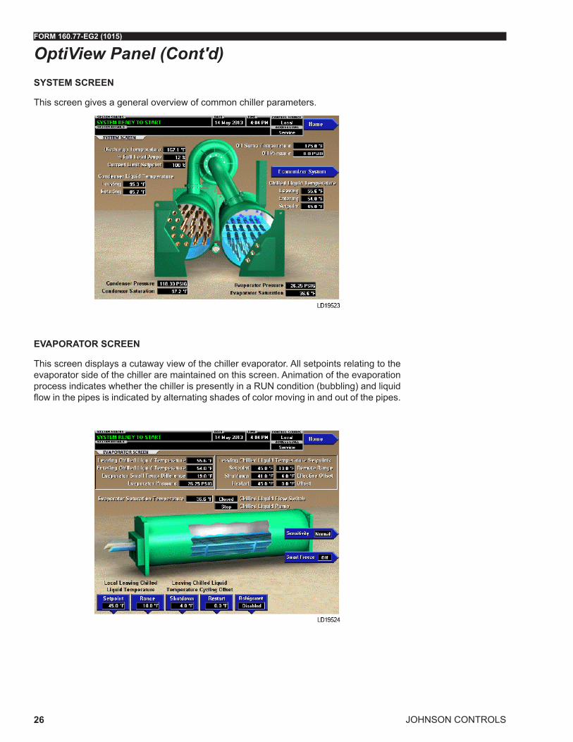
SYSTEM SCREEN
This screen gives a general overview of common chiller parameters.
EVAPORATOR SCREEN
This screen displays a cutaway view of the chiller evaporator. All setpoints relating to the evaporator side of the chiller are maintained on this screen. Animation of the evaporation process indicates whether the chiller is presently in a RUN condition (bubbling) and liquid flow in the pipes is indicated by alternating shades of color moving in and out of the pipes.
OptiView Panel (Cont'd)

FORM 160.77-EG2 (1015)
JOHNSON CONTROLS 27
CONDENSER SCREEN
This screen displays a cutaway view of the chiller condenser. All setpoints relating to the condenser side of the chiller are maintained on this screen. Animation indicates con-denser liquid flow.
ECONOMIZER SYSTEM SCREEN
This screen displays a cutaway of the chiller economizer.
OptiView Panel (Cont'd)

JOHNSON CONTROLS
FORM 160.77-EG2 (1015)
28
COMPRESSOR SCREEN
This screen displays a cutaway view of the chiller compressor, revealing the impeller, and shows all conditions associated with the compressor. Animation of the compressor impel-ler indicates whether the chiller is presently in a RUN condition. This screen also serves as a gateway to subscreens Hot Gas Bypass, Surge Protection, Compressor Capacity Cycling Setup and viewing and calibration of individual compressor functions.
OptiView Panel (Cont'd)
Primary Compressor Screen
Economizer Compressor Screen
FORM 160.77-EG2 (1015)
JOHNSON CONTROLS 29
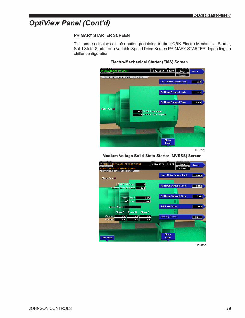
PRIMARY STARTER SCREEN
This screen displays all information pertaining to the YORK Electro-Mechanical Starter, Solid-State-Starter or a Variable Speed Drive Screen PRIMARY STARTER depending on chiller configuration.
OptiView Panel (Cont'd)
Electro-Mechanical Starter (EMS) Screen
Medium Voltage Solid-State-Starter (MVSSS) Screen

JOHNSON CONTROLS
FORM 160.77-EG2 (1015)
30
Medium Voltage Variable Speed Drive (MVVSD) Screen
HISTORY SCREEN
This screen allows the user to browse through the faults. In order to get a more thorough reporting of the system conditions at the time of the recorded shutdown, move to the sub-screen HISTORY DETAILS.
OptiView Panel (Cont'd)

FORM 160.77-EG2 (1015)
JOHNSON CONTROLS 31
OptiView Panel (Cont'd)SETPOINTS
This screen provides a convenient location for programming the most common chiller control setpoints. Changing setpoints and setup requires proper password access. This screen also serves as a gateway to a subscreen for defining the setup of general system parameters.
OPERATIONS
This screen allows definition of general parameters having to do with the operation of the chiller.

JOHNSON CONTROLS
FORM 160.77-EG2 (1015)
32
SCHEDULE SCREEN
This screen allows the user to program the Start/Stop times for any day of the week up to 6 weeks in advance. The user also has the ability to define a standard set of Start/Stop times that are utilized every week or specify exceptions to create a special week.
USER SCREEN
This screen allows definition of the language for the chiller to display and defines the unit of measure.
OptiView Panel (Cont'd)

FORM 160.77-EG2 (1015)
JOHNSON CONTROLS 33
SALES ORDER SCREEN
This screen displays the order parameters. This information is loaded at the factory or by the installation/service technician.
TRENDING SCREEN
On this screen, up to 6 user-selected parameters selected from a list of over 140, can be plotted in a time line graph format. The graph can be customized to record points once every second up to once every hour. There are two types of charts that can be created: a single or continuous screen. The single screen collects data for one screen width (450 data points across the X-axis) then stops. The continuous screen keeps collecting the data but the oldest data drops off the graph from left to right at the next data collection interval. For ease of identification, each plotted parameter, title and associated Y-axis labeling is color coordinated.
OptiView Panel (Cont'd)

JOHNSON CONTROLS
FORM 160.77-EG2 (1015)
34
Starters and Drives
MOTOR STARTER AND DRIVES
The YORK YK-EP is available with a variety of starter op tions for the primary compres-sor motor (See Table 2). The economizer compressor motor is always equipped with unit mounted, low voltage, YORK Solid-State-Starter (SSS).
OPTIONS FOR THE PRIMARY COMPRESSOR MOTOR STARTER JOHNSON CONTROLS MEDIUM VOLTAGE OPTISPEED™ DRIVE STARTER
When a YK-EP centrifugal chiller is equipped with the OptiSPEED variable speed drive, it incorporates advanced Adaptive Capacity Control logic, which continually optimizes chiller operation. It closely examines critical operating parameters, and then determines the most efficient way to operate. In addition, it allows optimized savings when using intelligent control strategies, such as chilled-water reset. Adaptive Capacity Control logic also accommodates the characteristics of the refrigerant used in the chiller — today and tomorrow.
The OPTISPEED variable speed drive is designed to vary the compressor motor speed by controlling the frequency and voltage of the electrical power to the motor. The capacity control logic automatically adjusts motor speed and compressor pre-rotation vane posi-tion independently for maximum part load efficiency by analyzing information fed to it by sensors located throughout the chiller.
The variable speed drive was specifically developed for commercial air-conditioning ap-plications. No one matches Johnson Controls experience in the application of variable
TABLE 2 - YORK YK-EP PRIMARY COMPRESSOR MOTOR STARTER OPTIONS
STARTER OPTIONSVOLTAGE/FREQUENCY
2300/50-60
3300/50-60
4000/60
4160/60
6000/50-60
6600/50-60
10000/50
11000/50
13200/60
MEDIUM VOLTAGE OPTISPEED VSD WITH FILTER X X X X X X X X
MEDIUM VOLTAGE SSS (UNIT MOUNTED)
X X X X
MEDIUM VOLTAGE SSS (FLOOR MOUNTED)
X X X X
AUTOTRANSFORMER 65% X X* X X Y Y Y Y Y
AUTOTRANSFORMER 80% X X X X Y Y Y Y Y
PRIMARY REACTOR 65% X X X X
PRIMARY REACTOR 80% X X X X
ACROSS THE LINE (ACL) X X X X Y Y Y Y Y
X = AvailableY = Available by Special Quote (SQ)* = Not available with 5DJ motor

FORM 160.77-EG2 (1015)
JOHNSON CONTROLS 35
Starters and Drives (Cont'd)
FIGURE 8 - OPTISPEED™ MEDIUM VOLTAGE VSD
speed drive technology to chillers. Since pioneering the concept in 1978, Johnson Con-trols has installed more variable speed drive chillers than all other chiller manufacturers combined.
Variable speed drives will save in both single-chiller installations and multiple-chiller in-stallations. In multiple-chiller installations, cycling chillers off as the building load falls will result in higher loads on the remaining chillers. This would seem to reduce the opportunity for drives to save energy. However, even though chiller loads remain high, entering con-denser-water temperature has most likely fallen. And, reductions in entering condenser water temperature offer a far greater potential to enhance chiller efficiency than do load reductions. Therefore, variable speed drive will deliver major energy savings in multiple-chiller plants, too.
The variable speed drive is factory-packaged and configured for easy remote mounting. It is designed to vary the compressor motor speed by controlling the frequency and volt-age of the electrical power to the motor. The capacity control logic automatically adjusts motor speed and compressor pre-rotation vane position independently for maximum part load efficiency by analyzing information fed to it by sensors located throughout the chiller
The variable speed drive is mounted in a NEMA-1 enclosure and comes with a certifica-tion label from a nationally recognized testing laboratory. The connection points between the drive and chiller are factory labeled. Electrical lugs for incoming power wiring are NOT provided.

JOHNSON CONTROLS
FORM 160.77-EG2 (1015)
36
FIGURE 9 - TYPICAL OPTISPEED MVVSD 1000-2000 HP - 4160V
The variable speed drive provides automatic displacement power factor correction to 0.98 or better at all load conditions. Separate displacement power factor correction capacitors are not required.
Standard features include: a lockable door interlocked disconnect switch; UL listed ground fault protection; over-voltage and under-voltage protection; 3-phase sensing motor over-current protection; single-phase protection; insensitive to phase rotation; over-tempera-ture protection; digital readout at the Control Center of:
• Output frequency
• 3-phase output voltage
• 3-phase output current
• Input power (kW)
• Self diagnostic service parameters
• Kilowatt-hours (kWH)
• Input kVa
• Total power-factor
• 3-phase input voltage
• 3-phase input current
• Self diagnostic service parameters
The OptiSpeed Medium Voltage Variable Speed Drive has the following advantages:
• Lowest chiller life cycle through part load energy savings.
• Application-specific designs enable efficient , precise load control and seamless in-tegration with equipment control panel and BAS.
• Soft start with input current lower than full load current.
• Smooth acceleration reduces stresses at most operating conditions.
• Reduces compressor sound levels at most operating conditions.
Starters and Drives (Cont'd)
LD12119

FORM 160.77-EG2 (1015)
JOHNSON CONTROLS 37
• Rugged and reliable with no moving parts.
• IEEE-519 2014 compliant. No optional filter needed.
• Multi-level PWM output closely simulates a true sine wave, allowing the use of stan-dard motors and bearings.
MEDIUM VOLTAGE SOLID-STATE-STARTER
The Medium Voltage Solid-State-Starter is a reduced voltage in-line bypass starter that controls and maintains a constant current flow to the motor during startup. Power and control wiring between the starter and the chiller for the unit mounted version is factory-installed. Available for 2300 - 4160 volts Table 3 - Medium Voltage Solid-State-Starter Voltages on page 37, the starter enclosure is NEMA-1, with a hinged access door with lock and key. Electrical lugs for incoming power wiring are not provided.
Standard Features include digital readout at the Control Center of the following:
Display Only
• 3-phase input voltage
• 3-phase current
• Input Power (kW)
• Killowatt-Hours (kWh)
• Starter Model
• Motor Run (LED)
• Motor Current % Full Load Amps
• Current Limit Setpoints
• Pulldown Demand Time Left
Programmable
• Local Motor Current Limit
• Pulldown Demand Limit
• Pulldown Demand Time
TABLE 3 - MEDIUM VOLTAGE SOLID-STATE-STARTER VOLTAGESMEDIUM VOLTAGE
SOLID-STATE-STARTER 60 HZ 50 HZ
2300V 3300V 4000V 4160V 3300V
UNIT MOUNTED X X X X X
FLOOR MOUNTED X X X X X
X = Available
Starters and Drives (Cont'd)

JOHNSON CONTROLS
FORM 160.77-EG2 (1015)
38
FIGURE 10 - UNIT MOUNTED MV SOLID -STATE-STARTER
Other features include: low line voltage; 115-volt control transformer; three-leg motor current sensing overloads; phase rotation and single-phase failure protection; high tem-perature safety protection; motor current imbalance and under-voltage safeties; open and shorted SCR protection; momentary power interruption protection. The Solid-State-Starter is air cooled generating about the same heat as an auto-transformer E-M starter. Ground fault protection and surge protection are also standard features. The 50,000 amp short circuit withstand rating is in accordance with UL Standard 508.
The Medium Voltage Solid-State-Starter has the following advantages: • Smooth, controlled start profile
• Unit mounted, factory wired and tested
• Rugged & reliable with no moving parts
• Adjustable acceleration time
• Application-specific designs enable seamless integration with equipment control panel and BAS
FLOOR MOUNTED ELECTRO-MECHANICAL STARTER - (FIELD-INSTALLED BY OTHERS)
Characteristics
For comparison purposes, here is a description of some of the general characteristics of electromechanical starters. Until the development of the Solid-State-Starter, all centrifu-gal chillers required the use of starters using electro-mechanical contactors, which are limited to operating totally ON, or totally OFF. There was no alternative to this mechanical equipment with its inability to control applied voltage or power. This contrasts markedly with the YORK Medium Voltage Solid-State-Starter, which automatically maintains a pre-determined current during starting, regardless of variations in line voltage or motor load,
Starters and Drives (Cont'd)
LD13585

FORM 160.77-EG2 (1015)
JOHNSON CONTROLS 39
TABLE 4 - ELECTRO-MECHANICAL STARTER VOLTAGESSTARTER OPTIONS MEDIUM VOLTAGE / FREQUENCY
MV ACROSS THE LINE (ACL)
(FLOOR MOUNTED)
60HZ 50HZ2300 3300 4000 4160 6000 6600 13800 2300 3000 3300 6600 10000 11000
X X X X Y Y Y X X X Y Y YMV AUTOTRANSFORMER
65%(FLOOR MOUNTED)
60HZ 50HZ2300 3300 4000 4160 6000 6600 13800 2300 3000 3300 6600 10000 11000
X X X X Y Y Y X X* X* Y Y YMV AUTOTRANSFORMER
80%(FLOOR MOUNTED)
60HZ 50HZ2300 3300 4000 4160 6000 6600 13800 2300 3000 3300 6600 10000 11000
X X X X Y Y Y X X X Y Y YX = Available Y= available by Special Quote (SQ)* Not available with 5DJ motor
to give optimum acceleration without surges. Even with the addition of transformers, re-actors, resistors and additional contactors, timers and relays, the mechanical controllers offer limited adjustment, no positive control during starting and impose an objectionable transition spike. Some also require modified motors. A field-installed, electro-mechanical compressor motor starter is available, selected for proper size and type for job require-ments and in accordance with Johnson Controls Engineering Standard (R-1132) for Start-ers.
The most common failure mode of mechanical contactors is OFF. This occurs due to the coil open-circuiting or failure of a pole to make an electrical contact when it closes. How-ever, failure in the ON mode is not completely uncommon and can be a more dramatic type of failure, particularly if this failure mode exists at the same time that equipment safety controls are demanding a shutdown.
When contacts are “made,” the current builds up to its maximum value from zero, but when contacts are separated the current tends to flow through the gap thus formed and causes an arc. This arcing depends upon the voltage between the separating contacts. For medium voltage the use of vacuum contactors mitigates this problem somewhat by providing an environment to extinguish the arc. In the alternating current circuit, the sepa-ration of contacts may take place when the current is zero or maximum or at any value in between. An alternating current passes through zero and reverses its polarity twice during each cycle. If two or more contacts, one in each leg of a polyphase system, are separated simultaneously, the current values in each will vary. In a three-phase system, if one contact has zero current when opened, the other two contacts will have 86.6% of their maximum values, as an example. Additionally, when inductive circuits are broken, the voltage is increased at the contacts due to the counter (induced) EMF of the circuit. The instant the contacts separate, the voltage between them momentarily rises from zero to the maximum of the circuit, or higher if inductance is present in the circuit. In practice, every time the contacts close, they bounce. When they bounce, they arc. The arcing that occurs as the contacts make or break may result in rapid and excessive erosion of the contacts, causing prematurely short contact life.
Starters and Drives (Cont'd)

JOHNSON CONTROLS
FORM 160.77-EG2 (1015)
40
Types
YORK chillers are designed for use with the following types of electro-mechanical start-ers, here briefly described.
Across-the-Line (ACL) – These are the simplest and lowest-cost starters available. They apply full voltage to the three motor leads at the instant of starting. Since inrush is 100% of LRA and starting torque is 100%, this is the roughest type of starting on the motor and drive-line. In physical size, the ACL is the smallest of electro-mechanical starters and there is no transition surge. In most areas, utilities will not permit the use of this type of starter for chiller-size motors because of their large current draw on startup.
Auto-Transformer (AT) – These starters are reduced-voltage starters. Transformers are used to step down the voltage to the motor during startup. The result is reduced inrush current and starting torque at the level of 42% or 64% depending upon whether 65% or 80% voltage taps are used. They provide closed transition (with three-lead motors) with reduced line disturbance
ECONOMIZER COMPRESSOR MOTOR STARTER LOW VOLTAGE SOLID-STATE-STARTER
The YORK YK-EP centrifugal chiller uses a Low Voltage Solid-State-Starter in the econo-mizer motor. The Solid-State-Starter is compact and mounted on the unit. Power and control wiring between the starter and the chiller are factory-installed. Available for 200 - 575 volts Table 5 - Low Voltage Economizer Motor Starter Voltages on page 40, the starter enclosure is NEMA-1, with a hinged access door with lock and key. Electrical lugs for incoming power wiring are provided.
TABLE 5 - LOW VOLTAGE ECONOMIZER MOTOR STARTER VOLTAGESLOW VOLTAGE SOLID-STATE-
STARTER(UNIT MOUNTED)
380V 440V 460V 480V 575V 380V 400V 415V
X X X X X X X X
X=Available
FIGURE 11 - UNIT MOUNTED ECONOMIZER LV SOLID-STATE-STARTER
Starters and Drives (Cont'd)
00283vip

FORM 160.77-EG2 (1015)
JOHNSON CONTROLS 41
Standard Features include digital readout at the Control Center of the following:
Display Only
• 3-phase input voltage
• 3-phase current
• Input Power (kW)
• Killowatt-Hours (kWH)
• Starter Model
• Motor Run (LED)
• Motor Current % Full Load Amps
• Current Limit Setpoints
• Pulldown Demand Time Left
Programmable
• Local Motor Current Limit
• Pulldown Demand Limit
• Pulldown Demand Time
Other features include: low line voltage; 115-volt control transformer; three-leg, motor-current-sensing overloads; phase rotation and single-phase failure protection; high tem-perature safety protection; motor current imbalance and under-voltage safeties; open and shorted SCR protection; momentary power interruption protection. The Solid-State-Start-er is cooled by a closed-loop, fresh-water-circuit consisting of a water-to-water heat ex-changer and a fractional horsepower circulating pump. All interconnecting water piping is factory-installed and rated for 150 psig (10.3 barg) working pressure. Optional electronic trip circuit UL listed circuit breaker with integral ground fault protection is available with short circuit withstand ratings of:
• 65KA for 460V 200V, 400V models
• 50KA for 33L 575V models
• 35KA for 14L 575V models
• 22KA for 7L 575V models
A non-fused disconnect switch is also available. Both options are lockable.
Starters and Drives (Cont'd)

JOHNSON CONTROLS
FORM 160.77-EG2 (1015)
42
BAS REMOTE CONTROL
A communication interface permitting an exchange of chiller data with a BACnet MS/TP, Modbus RTU, LONworks or N2 Metasys network is available by means of an optional E-Link® Gateway. The Johnson Controls E-Link® Gateway mounts conveniently inside the Optiview panel and allows remote BAS networks to monitor values and issue commands to the chiller to control operation.
FACTORY INSULATION OF EVAPORATOR
Factory applied thermal insulation of the flexible, closed cell plastic type, 3/4" (19 mm) thick is attached with vapor proof cement to the evaporator shell, tube sheets, suction connection, and (as necessary) to the auxiliary tubing. Not included is the insulation of wa-terboxes and nozzles. This insulation will normally prevent condensation in environments with relative humidities up to 75% and dry bulb temperatures ranging from 50° to 90°F (10° to 32.2°C). 1 1/2" (38 mm) thick insulation is also available for relative humidities up to 90% and dry bulb temperatures ranging from 50° to 90°F (10° to 32.2°C).
KNOCK DOWN SHIPMENT
The YORK YK-EP chiller can be shipped diassembled into major subassemblies (evapo-rator, condenser, driveline, etc.) as required to rig into tight spaces. This is particularly convenient for existing buildings where equipment room access does not allow rigging a factory packaged chiller.
HIGH AMBIENT TEMPERATURE
Chiller modifications are available to allow for installation in areas where the ambients exceed 122°F (50°C). Special drive motors are required above 104°F (40°C). Evapora-tor design pressures must be increased for ambient temperatures above 112.8°F (45°C). The control panel is suited for 122°F (50°C) ambient. Medium voltage Solid-State-Starters must be derated and/or modified above 110°F (43.3°C). The free standing MVVSD option must be de-rated above it’s standard 104°F (40°C) limit.
HINGES AND DAVIT ARMS
Hinges and/or davit arms are available to ease serviceability. Hinges on the nozzle end of a compact water box still require that facility water piping be disconnected.
MARINE WATER BOXES
Marine water boxes allow service access for cleaning of the heat exchanger tubes without the need to break the water piping. Bolted on covers are arranged for convenient access. ANSI/AWWA C-606 couplings nozzle connections are standard; flanges are optional. Ma-rine water boxes are available for condenser and/or evaporator.
Accessories and Modifications

FORM 160.77-EG2 (1015)
JOHNSON CONTROLS 43
REFRIGERANT STORAGE/RECYCLING SYSTEM
A refrigerant storage/recycling system is a self contained package consisting of a refriger-ant compressor with oil separator, storage receiver, water cooled condenser, filter drier and necessary valves and hoses to remove, replace and distill refrigerant. All necessary controls and safety devices are a permanent part of the system.
SPRING ISOLATION MOUNTING
Spring isolation mounting is available instead of standard isolation mounting pads when desired. Four level adjusting, spring type vibration isolator assemblies with non skid pads are provided for field installation. Isolators are designed for one inch (25 mm) deflection.
SPECIAL MOTORS ENCLOSURES
Weather-Protected Type I Motors (WP-I)
A Weather-Protected Type I motor is an open machine with its ventilating passages con-structed to prevent the passage of a cylindrical rod ¾” in diameter. This affords protection against intrusion of rodents and some types of debris. These are regularly used in the pulp industry and where grime is present.
Weather-Protected Type II Motors (WP-II)
A Weather-Protected Type II motor has, in addition to the enclosure defined for Weather- Protected Type I motor, ventilating passages at both intake and exhaust so arranged that high-velocity air and airborne particles, blown into the motor, can be discharged without entering the internal ventilating passages leading directly to the electric parts of the ma-chine itself. Space heaters are required with WP-II.
Totally Enclosed Fan-Cooled Motors (TEFC)
TEFC motors are used where the location is extremely dirty, dusty, or wet, both indoors and outdoors. A totally enclosed fan-cooled unit is enclosed to prevent the free exchange of air between the inside and outside of the case but not sufficiently enclosed as to be termed air-tight. It is air-cooled by means of a fully guarded fan blowing cooling air over the outside of the motor. The fan is externally mounted on the motor shaft.
Totally Enclosed Air-to-Air Cooled (TEAAC)
TEAAC motors are used when the environment is dirty or corrosive. A TEAAC motor is a totally enclosed motor, cooled by circulating the internal air through an air-to-air heat exchanger.
Totally Enclosed Water-to-Air Cooled (TEWAC)
TEWAC motors are used when the environment is dirty or corrosive, in hazardous ar-eas, or where minimum noise levels are required. A TEWAC motor is a totally enclosed machine which is cooled by circulating internal air which, in turn, is cooled by circulating water. It is provided with an internal water-cooled heat exchanger for cooling the internal air and fans, integral with the rotor shaft for circulating the internal air.
There are job applications, primarily in manufacturing plants, and process applications, where more motor protection is required. Listed below are several alternatives. NOTE: Chiller certification to UL by a third party could be affected. Contact a Johnson Controls sales office for a specific selection.
Accessories and Modifications (Cont'd)

JOHNSON CONTROLS
FORM 160.77-EG2 (1015)
44
TUBE AND/OR TUBE SHEET MATERIALS AND/OR WATERBOX COATING
Alternate copper-nickel or titanium tubes can be provided in lieu of standard copper for condenser and/or evaporator for protection against aggressive water conditions. Tube sheets may be of the clad type. Epoxy or ceramic coating may be applied to water boxes or to tubesheet and water boxes.
WATER FLANGES
Four 150 lb. ANSI raised-face flanges for condenser and evaporator water connections are factory-welded to water nozzles. Companion flanges, bolts, nuts and gaskets are not included.
Accessories and Modifications (Cont'd)

FORM 160.77-EG2 (1015)
JOHNSON CONTROLS 45
Application Data
The following discussion is a user’s guide in the application and installation of YK-EP chill-ers to ensure the reliable, trouble free life for which this equipment was designed. While this guide is directed towards normal, water chilling applications, the Johnson Controls sales representative can provide complete recommendations on other types of applica-tions.
BRINE APPLICATIONS
Various types of brine can be used in both the evaporator and condenser in lieu of water. The OptiView panel is programmed in the factory to allow extending the evaporator leav-ing brine temperature setpoint below 36°F (2.2°C). The low evaporator pressure cutout is factory programmed to the appropriate value depending on the percentage concentration and type of brine solution.
When the chiller is not running, brine should not be flowing through the evaporator. How-ever, if there is brine flowing through the evaporator, there must be flow through the con-denser to prevent tubes from freezing. In brine applications, the condenser pump control will close when the condenser saturation temperature reaches 35°F (1.7°C) and the pump will shut off when the temperature increases to 40°F (4.4°C). This is applicable if tied to the condenser pump control.
LOCATION
YORK YK-EP chillers are virtually vibration free and may generally be located at any level in a building where the construction will support the total system operating weight.
The unit site must be a floor, mounting pad or foundation which is level within 1/4" (6.4 mm) and capable of supporting the operating weight of the unit.
Sufficient clearance to permit normal service and maintenance work should be provided all around and above the unit. Additional space should be provided at one end of the unit to permit cleaning of evaporator and condenser tubes as required. A doorway or other properly located opening may be used.
The chiller should be installed in an indoor location where temperatures range from 40°F to 104°F (4.4°C to 40°C). The dew point temperature in the equipment room must be be-low the entering condenser water temperature to prevent condensing water vapor inside of the solid-state-starter or low voltage variable speed drive cabinet (if applicable). Appli-cations using cooling sources other than evaporative or closed loop air exchange meth-ods need to request a factory-supplied temperature control valve to prevent condensation inside the solid-state-starter or low voltage variable speed drive cabinet (if applicable). Other areas susceptible to water vapor condensate are outside of the condenser shell and condenser water boxes. Example applications include when the condenser water comes from chilled water, wells, river, or other low temperature fluids.

JOHNSON CONTROLS
FORM 160.77-EG2 (1015)
46
Application Data (Cont'd)MULTIPLE UNITS
Selection – Many applications require multiple units to meet the total capacity requirements as well as to provide flexibility and some degree of protection against equipment shutdown. There are several common unit arrangements for this type of application. The YK-EP chiller has been designed to be readily adapted to the requirements of these various arrangements.
Parallel Arrangement (Refer to Figure 12 - PARALLEL EVAPORATORS PARALLEL CON-DENSERS on page 46) – Chillers may be applied in multiples with chilled and condenser water circuits connected in parallel between the units. Fig. 2 represents a parallel arrangement with two chillers. Parallel chiller arrangements may consist of equally or unequally sized units. When multiple units are in operation, they will load and unload at equal percentages of design full load for the chiller.
COND. 1
COND. 2
EVAP. 1
EVAP. 2
LD18370
S – Temperature Sensor for Chiller Capacity Control
T – Thermostat for Chiller Capacity Control
FIGURE 12 - PARALLEL EVAPORATORS PARALLEL CONDENSERS
Depending on the number of units and operating characteristics of the units, loading and unloading schemes should be designed to optimize the overall efficiency of the chiller plant. It is recommended to use an evaporator bypass piping arrangement to bypass fluid around evaporator of any unit which has cycled off at reduced load conditions. It is also recommended to alternate the chiller cycling order to equalize chiller starts and run hours.
Series Arrangement (Refer to Figure 13 - SERIES EVAPORATORS PARALLEL CON-DENSERS on page 47) – Chillers may be applied in pairs with chilled water circuits connected in series and condenser water circuits connected in parallel. All of the chilled water flows through both evaporators with each unit handling approximately one half of the total load. When the load decreases to a customer selected load value, one of the units will be shut down by a sequence control. Since all water is flowing through the oper-ating unit, that unit will cool the water to the desired temperature.

FORM 160.77-EG2 (1015)
JOHNSON CONTROLS 47
Application Data (Cont'd)
EVAP. 1 EVAP. 2
T S1 S2
COND. 1
COND. 2
LD18371
FIGURE 13 - SERIES EVAPORATORS PARALLEL CONDENSERS
Series Counter Flow Arrangement (Refer to Figure 14 - SERIES EVAPORATORS SERIES-COUNTER FLOW CONDENSERS on page 47) - Chillers may be applied in pairs with chilled water circuits connected in series and with the condenser water in series counter flow. All of the chilled water flows through both evaporators. All of the condenser water flows through both condensers. The water ranges are split, which allows a lower temperature difference or “head” on each chiller, than multiple units in parallel. For equal chillers, the machine at higher temperature level will typically provide slightly more than half the capacity. The compressor motors and gear codes on the two chillers are often matched, such that the high temperature machine can operate at the low temperature conditions when one unit is cycled off at part loads (as compared to series-parallel chillers which are typically not identical).
LD18372
S – Temperature Sensor for Chiller Capacity Control
T – Thermostat for Chiller Capacity Control
FIGURE 14 - SERIES EVAPORATORS SERIES-COUNTER FLOW CONDENSERS
Series counter flow application can provide a significant building energy savings for large capacity plants which have chilled and condenser water temperature ranges greater than typical AHRI design conditions.
REFRIGERANT RELIEF PIPING
Each chiller is equipped with dual pressure relief valves on the condenser and two dual relief valves on the evaporator, or two single relief valves on the evaporator if the optional refrigerant isolation valves are ordered. The dual relief valves on the condenser are re-dundant and allow changing of either valve while the unit is fully charged. The purpose

JOHNSON CONTROLS
FORM 160.77-EG2 (1015)
48
of the relief valves is to quickly relieve excess pressure of the refrigerant charge to the atmosphere, as a safety precaution in the event of an emergency such as fire. They are set to relieve at an internal pressure as noted on the pressure vessel data plate, and are provided in accordance with ASHRAE 15 safety code and ASME or applicable pressure vessel code.
Sized to the requirements of applicable codes, a vent line must run from the relief device to the outside of the building. This refrigerant relief piping must include a cleanable, verti-cal leg dirt trap to catch vent stack condensation. Vent piping must be arranged to avoid imposing a strain on the relief connection and should include one flexible connection.
SOUND AND VIBRATION CONSIDERATIONS
A YK-EP chiller is not a source of objectionable sound and vibration in normal air condi-tioning applications. Neoprene isolation mounts are furnished as standard with each unit. Optional level adjusting spring isolator assemblies designed for 1” (25 mm) static deflec-tion are available from Johnson Controls.
YK-EP chiller sound pressure level ratings will be furnished on request.
Control of sound and vibration transmission must be taken into account in the equipment room construction as well as in the selection and installation of the equipment.
THERMAL INSULATION
No appreciable operating economy can be achieved by thermally insulating the chiller. However, the chiller’s cold surfaces should be insulated with vapor barrier insulation suf-ficient to prevent condensation. A chiller can be factory-insulated with 3/4” (19 mm) or 1 1/2” (38 mm) thick insulation, as an option. This insulation will normally prevent condensa-tion in environments with dry bulb temperatures of 50°F to 90°F (10°C to 32°C) and rela-tive humidities of up to 75% [3/4” (19 mm) thickness] or 90% [1 1/2” (38 mm) thickness]. The insulation is painted and the surface is flexible and reasonably resistant to wear. It is intended for a chiller installed indoors and, therefore, no protective covering of the insula-tion is usually required. If insulation is applied to the water boxes at the job site, it must be removable to permit access to the tubes for routine maintenance.
VENTILATION
The ASHRAE Standard 15 Safety Code for Mechanical Refrigeration requires that all ma-chinery rooms be vented to the outdoors utilizing mechanical ventilation by one or more power driven fans. This standard, plus National Fire Protection Association Standard 90A, state, local and any other related codes should be reviewed for specific requirements. Since the YK-EP chiller motors are air cooled, ventilation should allow for the removal of heat from the motor.
In addition, the ASHRAE Standard 15 requires a refrigerant vapor detector to be em-ployed for all refrigerants. It is to be located in an area where refrigerant from a leak would be likely to concentrate. An alarm is to be activated and the mechanical ventilation started at a value no greater than the TLV (Threshold Limit Value) of the refrigerant.
Application Data (Cont'd)

FORM 160.77-EG2 (1015)
JOHNSON CONTROLS 49
WATER CIRCUITS
Flow Rate – For normal water chilling duty, evaporator and condenser flow rates are per-mitted at water velocity levels in the heat exchangers tubes of between 3 ft/sec and 12 ft/sec (0.91 m/s and 3.66 m/s) for constant flow applications. Variable flow applications are possible, and initial chiller selections should be made accordingly to allow proper range of flow while maintaining the minimum velocity indicated at the certified rating for the unit. Variable flow in the condenser is not recommended, as it generally raises the energy con-sumption of the system by keeping the condenser pressure high in the chiller. Additionally, the rate of fouling in the condenser will increase at lower water velocities associated with variable flow, raising system maintenance costs. Cooling towers typically have narrow ranges of operation with respect to flow rates, and will be more effective with full design flow. For normal water chilling duty, leaving chilled water temperatures may be selected between 38°F (3.3°C) [36°F (2.2°C) with Smart Freeze enabled] and 70°F (21.1°C) to obtain temperature deltas between entering chilled and leaving chilled water temperature of 3°F up to 30°F (1.7°C and 16.7°C).
Convenience Considerations – To facilitate the performance of routine maintenance work, some or all of the following steps may be taken by the purchaser. Evaporator and condenser water boxes are equipped with plugged vent and drain connections. If desired, vent and drain valves may be installed with or without piping to an open drain. Pressure gauges with stopcocks and stop valves may be installed in the inlets and outlets of the condenser and chilled water line as close as possible to the chiller. An overhead monorail or beam may be used to facilitate servicing.
Connections – The standard chiller is designed for 150 PSIG (10.3 bar) design working pressure in both the chilled water and condenser water circuits. The connections (water nozzles) to these circuits are furnished with grooves to ANSI/AWWA C 606 Standard for grooved and shouldered joints. Piping should be arranged for ease of disassembly at the unit for tube cleaning. All water piping should be thoroughly cleaned of all dirt and debris before final connections are made to the chiller.
Fluid Strainer – A fluid strainer with perforated holes no larger than 1/8” (3.2 mm) must be field installed in the chilled fluid inlet line as close as possible to the chiller. If located close enough to the chiller, the chilled fluid pump may be protected by the same strainer. The strainer is to protect the chiller from debris or objects which could block flow through indi-vidual heat exchanger tubes. A reduction in flow through tubes could seriously impair the chiller performance or even result in tube freeze up. A thermal-type flow switch is factory installed in the evaporator nozzle and connected to the OptiView panel, which assures adequate chilled fluid flow during operation.
Low Entering Condenser Temperature – The unique design of YORK YK-EP chillers in the HVAC industry allows cold condenser fluid starts, without the nuisance trips experi-enced by most other manufacturers, as detailed below:
1. The condenser shell is higher than the evaporator, thus when the chiller is not in operation, gravity moves refrigerant from the condenser into the evaporator. On start-up, the compressor begins pumping refrigerant gas from the evaporator into the condenser and thus builds head pressure.
Application Data (Cont'd)

JOHNSON CONTROLS
FORM 160.77-EG2 (1015)
50
2. The butterfly type liquid expansion valve (variable orifice valve) is controlled by the condenser liquid level at the sub-cooler inlet. As that level increases, the valve would be driven open to allow maximum refrigerant flow. An additional expansion valve (variable orifice valve) is controlled by the liquid level in the economizer.
3. YORK YK-EP centrifugal chillers start-up with vanes closed, which reduces the amount of refrigerant gas pumped out of the evaporator over time.
4. The control system is set to stop the vanes from further opening if the evaporator fluid temperature achieves 1°F ( 0.6°C) above the trip set-point for low water tem-perature cut-out, typically 4°F (2.2°C) below set point.
At initial start-up, entering condenser water temperature may be 25° F (13.9° C) colder than standby chilled water temperature, but the minimum temperature should be above the freezing point of the chilled liquid.
Handling cold condenser fluid at the onset of changeover from free cooling with tower/heat exchangers is often a realistic requirement. The chiller will start and continue to oper-ate because pressure differential increases quickly, thus preventing nuisance trips on low evaporator pressure usually caused by: system depression, refrigerant stack-up in the condenser, and starvation of the evaporator.
For continuous operation, the minimum entering condenser fluid temperature for both full and part load conditions is provided by the following equation:
English
Min. ECWT = LCHWT – C RANGE + 5°F + 12 ( %Load )100
SI
Min. ECWT = LCHWT – C RANGE + 2.8°C + 6.6 ( %Load )100
Where:
ECWT = entering condensing water temperature
LCHWT = leaving chilled water temperature
C RANGE = condensing water temperature range at the given load condition.
Examples:
a. 2000 TR (7032 kW) chiller
b. 44°F (6.7°C) leaving chilled fluid temperature
c. 85/94.3°F (29.4/34.6°C) condenser fluid temperature range @ full load
English Example
Application Data (Cont'd)

FORM 160.77-EG2 (1015)
JOHNSON CONTROLS 51
At full load: Min. ECFT = 44 – (94.3 - 85) + 5 + 12 ( 100 ) = 44 – 9.3 + 5 + 12 =100
Min. ECFT = 51.7 °F
At 20% load:
Min. ECFT = 44 – (87 - 85) + 5 + 12 ( 20 ) = 44 – 2 + 5 + 2.4 =100
Min. ECFT = 49.4 °F
SI Example
At full load: Min. ECFT = 6.7 – (34.6 - 29.4) + 2.8 + 6.6 ( 100 )100
= 6.7 – 5.2 + 2.8 + 6.6 =
Min. ECFT = 10.9°C
At 20% load:
Min. ECFT = 6.7 – (30.6 - 29.4) + 2.8 + 6.6 ( 20 )100
= 6.7 – 1.2 + 2.8 + 1.3 =
Min. ECFT = 9.6 °C
Application Data (Cont'd)

JOHNSON CONTROLS
FORM 160.77-EG2 (1015)
52
TABLE 6 - WATER FLOW RATE LIMITS GPM (L/S) BASED ON CONSTANT FLOW APPLICATION AND STANDARD TUBES
COMPLENGTH
(FT)FLOW/PD
EVAPORATOR CONDENSERSHELL CODE
1 PASS 2 PASS 3 PASS SHELL CODE
1 PASS 2 PASS 3 PASSMIN MAX MIN MAX MIN MAX MIN MAX MIN MAX MIN MAX
K7 22
GPM
BB
3170 12680 1580 3850 1050 2550
BB
5360 19260 2690 6840 1789 4610 (L/S) 200 800 100 243 66 161 338 1215 170 432 113 291
Ft 4.9 59.2 9.0 45.0 13.3 67.5 4.7 46.1 9.4 45.0 20.9 67.5 (kPa) 15 177 27 134 40 202 14 138 28 134 62 202 GPM
BC
3910 15650 1950 4710 1300 3130
BC
5880 21230 2940 7450 1964 5050 (L/S) 247 987 123 297 82 197 371 1339 185 470 124 319
Ft 5.1 62.7 9.2 45.0 13.7 67.5 4.8 47.9 8.6 45.0 19.4 67.5 (kPa) 15 187 27 134 41 202 14 143 26 134 58 202 GPM
BD
4720 18820 2360 5630 1570 3730
BD
6400 23080 3200 8050 (L/S) 298 1187 149 355 99 235 404 1456 202 508
Ft 5.4 66.5 9.4 45.0 14.0 67.5 5.0 49.4 8.7 45.0 (kPa) 16 199 28 134 42 202 15 148 26 134 GPM
B5
3240 12980 1610 5120 1080 3360
B5
4250 15320 2130 7120 1417 4890 (L/S) 204 819 102 323 68 212 268 967 134 449 89 309
Ft 3.1 39.2 5.4 45.0 8.2 67.5 3.1 31.0 8.1 45.0 18.0 67.5 (kPa) 9 117 16 134 24 202 9 93 24 134 54 202 GPM
B6
3880 15540 1830 6070 1290 4010
B6
5260 18850 2630 8600 1753 5950 (L/S) 245 980 115 383 81 253 332 1189 166 543 111 375
Ft 3.3 42.2 5.6 45.0 8.4 67.5 3.3 32.8 5.8 45.0 17.2 67.5 (kPa) 10 126 17 134 25 202 10 98 17 134 51 202 GPM
B7
4380 17570 2190 6800 1460 4500
B7
6140 22107 3070 9800 2047 6820 (L/S) 276 1108 138 429 92 284 387 1395 194 618 129 430
Ft 3.4 44.9 5.7 45.0 8.5 67.5 3.5 35.4 5.5 45.0 15.5 67.5 (kPa) 10 134 17 134 25 202 10 106 16 134 46 202 GPM
B8 B8
6780 24333 3390 10650 (L/S) 428 1535 214 672
Ft 3.6 37.2 5.7 45.0 (kPa) 11 111 17 134 GPM
CJ
4870 19380 2450 5790 1630 3770
CJ
6230 22440 3110 7990 2080 5320 (L/S) 307 1223 155 365 103 238 393 1416 196 504 131 336
Ft 5.5 67.4 9.5 45.0 14.2 67.0 4.9 48.8 8.5 45.0 18.5 67.5 (kPa) 16 201 28 134 42 200 15 146 25 134 55 202 GPM
CK
5380 21400 2690 6360 1800 4170
CK
6950 25010 3480 8550 2320 5900 (L/S) 339 1350 170 401 114 263 438 1578 220 539 146 372
Ft 5.7 70.6 9.5 45.0 14.4 66.4 5.1 51.1 8.6 45.0 16.8 67.5 (kPa) 17 211 28 134 43 198 15 153 26 134 50 202 GPM
CL
5560 23350 2930 6870 1960 4490
CL
7890 28240 3940 9900 (L/S) 351 1473 185 433 124 283 498 1782 249 625
Ft 5.9 74.3 9.7 45.0 14.6 65.8 5.4 54.1 8.8 45.0 (kPa) 18 222 29 134 44 197 16 162 26 134 GPM
C6
4040 16190 2030 6300 1350 4150
C6
4140 14910 2070 7050 1380 4770 (L/S) 255 1021 128 397 85 262 261 941 131 445 87 301
Ft 3.6 43.0 5.6 45.0 8.4 67.0 3.1 30.8 8.2 45.0 17.5 67.5 (kPa) 11 128 17 134 25 200 9 92 24 134 52 202 GPM
C7
4870 19400 2470 7470 1630 4900
C7
4970 17910 2850 8350 1650 5640 (L/S) 307 1224 156 471 103 309 314 1130 180 527 104 356
Ft 3.6 47.3 5.9 45.0 8.7 66.2 3.2 32.5 6.6 45.0 15.7 67.5 (kPa) 11 141 18 134 26 198 10 97 20 134 47 202 GPM
C8
5760 22830 2880 8660 1920 5710
C8
6480 23140 3250 10620 2160 7180 (L/S) 363 1440 182 546 121 360 409 1460 205 670 136 453
Ft 4.0 52.7 6.0 45.0 8.9 66.4 3.5 35.9 5.4 45.0 10.2 67.5 (kPa) 12 157 18 134 27 198 10 107 16 134 30 202 GPM
C9
6420 25560 3210 9550 3140 6290
C9
8090 29122 4050 12800 (L/S) 405 1613 203 603 198 397 510 1837 256 808
Ft 4.3 58.2 6.1 45.0 9.2 66.6 5.0 42.0 5.7 45.0 (kPa) 13 174 18 134 27 199 15 125 17 134
Application Data (Cont'd)

FORM 160.77-EG2 (1015)
JOHNSON CONTROLS 53
Electrical ConsiderationsSTARTERS
The primary motor of the YORK YK-EP can be supplied with a Variable Speed Drive (VSD). The chillers are also available with a factory-mounted and wired YORK Solid-State-Starter for medium voltage applications. Other types of remote mounted starters are available. Electro-mechanical starters can be furnished in accordance with YORK Stan-dard Specifications (R-1132). This will ensure that starter components, controls, circuits, and terminal markings will be suitable for required overall system performance. Remote-mounted medium voltage YORK Solid-State-Starters are also available. The economizer motor will always be equipped with a factory-mounted and wired YORK Low Voltage Solid-State-Starter.
Motor Voltage – The low voltage economizer motor (380 to 575 volts) is furnished with six leads (or multiples of six leads). Medium voltage (2300 and above) primary motors have three leads. Motor circuit conductor size must be in accordance with the National Electrical Code (N.E.C.), or other applicable codes, for the motor full load amperes (FLA). Flexible conduit should be used for the last several feet to the chiller in order to provide vibration isolation. Table 7 lists the allowable variation in voltage supplied to the chiller motor. The unit name plate is stamped with the specific motor voltage, and frequency for the appropriate motor.
TABLE 7 - MOTOR VOLTAGE VARIATIONS*
FREQUENCYRATED
VOLTAGENAMEPLATE
VOLTAGE
OPERATING VOLTAGEMIN. MAX.
60HZ
380 380 342 415460 440/460/480 414 508575 575/600 520 6352300 2300 2070 25303300 3300 2970 36304000 4000/4160 3600 4576
50HZ
380 380/400 342 423415 415 374 440
2300 2300 2070 25303300 3300 2970 3630
* For motor voltages above 4160V/60Hz and 3300V/50Hz, contact your local Johnson Controls Sales office for a specific selection
Copper Conductors – Only copper conductors should be connected to compressor mo-tors and starters. Aluminum conductors have proven to be unsatisfactory when connected to copper lugs. Aluminum oxide and the difference in thermal conductivity between copper and aluminum cannot guarantee the required tight connection over a long period of time.
Power Factor Correction Capacitors – Capacitors can be applied to a chiller for the purpose of power factor correction. For remote-mounted electro-mechanical starters, the capacitors should be located on the load side of the starter. The capacitors must be sized and installed to meet the National Electrical Code and be verified by Johnson Controls.

JOHNSON CONTROLS
FORM 160.77-EG2 (1015)
54
Power Supply for Controls and Motors:
YK-EP model “B” using a Floor-Mounted MV-VSD as Primary Starter:
• Primary Driveline:
• Floor-mounted Primary MV-VSD Starter: Power supplied by Customer. (MV/3P/50-60Hz + 115V/1P/50-60Hz (2kVa)
• Primary MV Motor: Powered from MV VSD: Field wiring connection provided by Customer. (MV/3P/50-60Hz)
• Economizer Motor Space Heater: Optionally powered by Optiview Control Pan-el: Wiring is factory connected, but if this option is not ordered, the power and wiring connection will be supplied by Customer. (115V/1P/50-60Hz for 500W or less)
• Primary Variable Speed Oil Pump Panel (VSOP): Powered from Primary MV-VSD Starter. Field wiring connection provide by Customer. (LV/3P/50-60Hz)
• Economizer Driveline:
• Unit-Mounted Economizer LV Solid-State-Starter: Power supplied by Custom-er. (LV/3P/50-60Hz)
• Economizer LV motor: Powered from Economizer LV Solid-State-Starter: Fac-tory wiring connected. (LV/3P/50- 60Hz)
• Economizer Motor Space Heater: Optionally powered by Optiview Control Pan-el: Wiring is factory connected, but if this option is not ordered, the power and wiring connection will be supplied by Customer. (115V/1P/50-60Hz for 500W or less)
• Economizer Variable Speed Oil Pump Control Panels (VSOP): Powered from Primary LV Solid-State-Starter. Factory wiring connected. (LV/3P/50-60Hz)
• OptiSpeed™ Control Panel: Powered by Economizer Compressor VSOP and by Primary Compressor VSOP. Factory wiring connected. (115V/1P/50-60Hz)
YK-EP model “B” using a Unit-Mounted MV Solid-State-Starter as Primary Starter:
• Primary Driveline:
• Floor-mounted Primary MV Solid-State-Starter: Power supplied by Customer. (MV/3P/50-60Hz + 115V/1P/50-60Hz (2kVa)
• Primary MV Motor: Powered from MV Solid-State-Starter: Factory wiring con-nected. (MV/3P/50-60Hz)
• Economizer Motor Space Heater: Optionally powered by Optiview Control Pan-el: Wiring is factory connected, but if this option is not ordered, the power and wiring connection will be supplied by Customer. (115V/1P/50-60Hz for 500W or less)
• Primary Variable Speed Oil Pump Panel (VSOP): Powered from Primary MV Solid-State-Starter. Factory wiring connected. (LV/3P/50-60Hz)
Electrical Considerations (Cont'd)

FORM 160.77-EG2 (1015)
JOHNSON CONTROLS 55
• Economizer Driveline:
• Unit-Mounted Economizer LV Solid-State-Starter: Power supplied by Custom-er. (LV/3P/50-60Hz)
• Economizer LV motor => Powered from Economizer LV Starter: Factory wiring connected. (LV/3P/50- 60Hz)
• Economizer Motor Space Heater: Optionally powered by Optiview Control Pan-el: Wiring is factory connected, but if this option is not ordered, the power and wiring connection will be supplied by Customer. (115V/1P/50-60Hz for 500W or less)
• Economizer Variable Speed Oil Pump Control Panels (VSOP): Powered from Primary LV Solid-State-Starter. Factory wiring connected. (LV/3P/50-60Hz)
• OptiSpeed™ Control Panel: Powered by Economizer Compressor VSOP and by Primary Compressor VSOP. Factory wiring connected. (115V/1P/50-60Hz)
YK-EP model “B” using a MV Starter (Electro-Mechanical) as Primary Starter:
• Primary Driveline:
• Floor-mounted Primary MV Starter (Electro-Mechanical): Power supplied by Customer. (MV/3P/50-60Hz + 115V/1P/50-60Hz (2kVa)
• Primary MV Motor: Powered from MV Starter (Electro Mechanical): Field wir-ing connection provided by Customer. (MV/3P/50-60Hz)
• Economizer Motor Space Heater: Optionally powered by Optiview Control Pan-el: Wiring is factory connected, but if this option is not ordered, the power and wiring connection will be supplied by Customer. (115V/1P/50-60Hz for 500W or less)
• Primary Variable Speed Oil Pump Control Panels (VSOP): Powered from Pri-mary MV Starter (Electro Mechanical). Field wiring connection provided by Customer. (LV/3P/50-60Hz)
• Economizer Driveline:
• Unit-Mounted Economizer LV Solid-State-Starter: Power supplied by Custom-er. (LV/3P/50-60Hz)
• Economizer LV motor: Powered from Economizer LV Starter: Factory wiring connected. (LV/3P/50- 60Hz)
• Economizer Motor Space Heater: Optionally powered by Optiview Control Pan-el: Wiring is factory connected, but if this option is not ordered, the power and wiring connection will be supplied by Customer. (115V/1P/50-60Hz for 500W or less)
• Economizer Variable Speed Oil Pump Panel (VSOP): Powered from Primary LV Solid-State-Starter. Factory wiring connected. (LV/3P/50-60Hz)
• OptiSpeed Control Panel: Powered by Economizer Compressor VSOP and by Primary Compressor VSOP. Factory wiring connected. (115V/1P/50-60Hz)
Electrical Considerations (Cont'd)

JOHNSON CONTROLS
FORM 160.77-EG2 (1015)
56
Ampacity on Load Side of Starter – Electrical power wire size to the chiller is based on the minimum unit ampacity. For remote starters, the National Electrical Code defines the calculation of ampacity, as summarized below. More specific information on actual amper-age ratings will be supplied with the submittal drawings.
• Three lead type of starting (Across the Line, Autotransformer and Primary Reactor) Minimum circuit ampacity per conductor (1 of 3):
Ampacity = 1.25 x compressor motor amps
Ampacity on Line Side of Starter – The only load applied to the starter is the compres-sor motor load. All other low voltage devices must be fed by an additional power supply feed.
Minimum Circuit Ampacity - 125% of compressor motor amps.
Branch Circuit Over-current Protection – The branch circuit over-current protection device(s) should be a time-delay type, with a minimum rating equal to the next standard fuse/breaker rating above the calculated value. It is calculated taking into account the compressor motor amps and may also include the control transformer and oil pump motor. Refer to submittal drawings for the specific calculations for each application.
Variable Speed Oil Pump (VSOP) Control Panel Power Supply – Controls – For re-mote starters or medium voltage variable speed drive a 115 volt, single phase, 60 or 50 Hz 2 kVa power supply must be furnished at the starter. For chillers with a unit mounted solid- state-starter, the variable speed oil pump control panel power will not require an additional control power transformer, but will be included in the Johnson Controls furnished primary starter. For chillers without a unit-mounted primary starter, a 3-phase supply will be re-quired for the auxiliary power (heater and oil pump).The economizer compressor auxiliary power is always sourced from the economizer starter which is factory unit-mounted.
MOTOR ELECTRICAL DATA
Select the smallest motor available which equals or exceeds the input power (kW) from the chiller rating program in Table 9 - 60 HZ Electrical Data For Primary Motor on page 57. The full load amperes (FLA) listed in the tables are the maximum values and corre-spond to the maximum motor kW listed. When the input power (kW) is less than maximum motor kW, the FLA should be reduced per the following equation:
FLA =Motor kW x Max. Motor FLA
Max. Motor kW
The benefit from the FLA correction is the possible use of smaller power wiring and/or starter size.
The locked rotor amperes (LRA) are read directly from Tables 6 and 7 for specific Motor Code and voltage. This is because the LRA is dependent only on motor size and voltage and is independent of input power (kW).
Inrush amperes (IRA) depend on LRA and the type of starter applied. The inrush can be calculated using a percentage of LRA shown in Table 13 - Primary And Economizer Com-pressor Motor Starters on page 59.
Electrical Considerations (Cont'd)
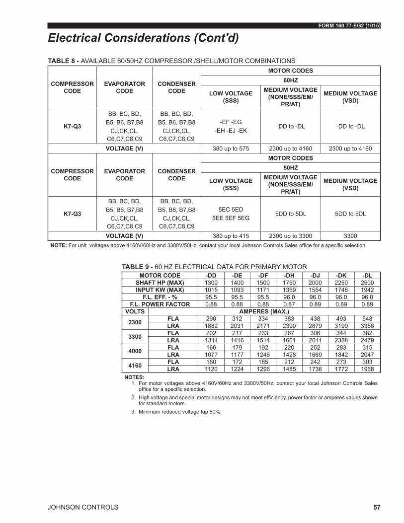
FORM 160.77-EG2 (1015)
JOHNSON CONTROLS 57
TABLE 8 - AVAILABLE 60/50HZ COMPRESSOR /SHELL/MOTOR COMBINATIONS
COMPRESSOR CODE
EVAPORATOR CODE
CONDENSER CODE
MOTOR CODES60HZ
LOW VOLTAGE (SSS)
MEDIUM VOLTAGE (NONE/SSS/EM/
PR/AT)
MEDIUM VOLTAGE (VSD)
K7-Q3
BB, BC, BD, B5, B6, B7,B8
CJ,CK,CL, C6,C7,C8,C9
BB, BC, BD, B5, B6, B7,B8
CJ,CK,CL, C6,C7,C8,C9
-EF -EG -EH -EJ -EK
-DD to -DL -DD to -DL
VOLTAGE (V) 380 up to 575 2300 up to 4160 2300 up to 4160
COMPRESSOR CODE
EVAPORATOR CODE
CONDENSER CODE
MOTOR CODES50HZ
LOW VOLTAGE (SSS)
MEDIUM VOLTAGE (NONE/SSS/EM/
PR/AT)
MEDIUM VOLTAGE (VSD)
K7-Q3
BB, BC, BD, B5, B6, B7,B8
CJ,CK,CL, C6,C7,C8,C9
BB, BC, BD, B5, B6, B7,B8
CJ,CK,CL, C6,C7,C8,C9
5EC 5ED 5EE 5EF 5EG
5DD to 5DL 5DD to 5DL
VOLTAGE (V) 380 up to 415 2300 up to 3300 3300NOTE: For unit voltages above 4160V/60Hz and 3300V/50Hz, contact your local Johnson Controls Sales office for a specific selection
TABLE 9 - 60 HZ ELECTRICAL DATA FOR PRIMARY MOTORMOTOR CODE -DD -DE -DF -DH -DJ -DK -DL
SHAFT HP (MAX) 1300 1400 1500 1750 2000 2250 2500INPUT KW (MAX) 1015 1093 1171 1359 1554 1748 1942
F.L. EFF. - % 95.5 95.5 95.5 96.0 96.0 96.0 96.0F.L. POWER FACTOR 0.88 0.88 0.88 0.87 0.89 0.89 0.89
VOLTS AMPERES (MAX.)
2300 FLA 290 312 334 383 438 493 548LRA 1882 2031 2171 2390 2879 3199 3356
3300 FLA 202 217 233 267 306 344 382LRA 1311 1416 1514 1661 2011 2388 2479
4000 FLA 166 179 192 220 252 283 315LRA 1077 1177 1246 1428 1669 1842 2047
4160 FLA 160 172 185 212 242 273 303LRA 1120 1224 1296 1485 1736 1772 1968
NOTES:1. For motor voltages above 4160V/60Hz and 3300V/50Hz, contact your local Johnson Controls Sales
office for a specific selection.2. High voltage and special motor designs may not meet efficiency, power factor or amperes values shown
for standard motors.3. Minimum reduced voltage tap 80%.
Electrical Considerations (Cont'd)

JOHNSON CONTROLS
FORM 160.77-EG2 (1015)
58
TABLE 10 - 50 HZ ELECTRICAL DATA FOR PRIMARY MOTORMOTOR CODE 5DD 5DE 5DF 5DG 5DH 5DJ 5DK 5DL
SHAFT HP (MAX) 1300 1400 1500 1650 1750 2000 2250 2500INPUT KW (MAX) 1015 1093 1171 1288 1359 1554 1748 1942
F.L. EFF. - % 95.5 95.5 95.5 95.5 96.0 96.0 96.0 96.0F.L. POWER FACTOR 0.88 0.88 0.88 0.88 0.89 0.89 0.89 0.89
VOLTS AMPERES (MAX.)
3300 FLA 202 217 233 256 267 306 344 382LRA 1135 1415 1415 1415 1667 1836 2233 2481
NOTES:1. For motor voltages above 4160V/60Hz and 3300V/50Hz, contact your local Johnson Controls Sales of-
fice for a specific selection.2. High voltage and special motor designs may not meet efficiency, power factor or amperes values shown
for standard motors.3. Minimum reduced voltage tap 80%.
TABLE 11 - 60 HZ ELECTRICAL DATA FOR ECONOMIZER MOTORMOTOR CODE -EF -EG -EH -EJ -EK
SHAFT HP (MAX) 154 177 201 237 270INPUT KW (MAX) 122 139 158 185 211
F.L. EFF. - % 94.5 95 95 95.4 95.4F.L. POWER FACTOR 0.88 0.88 0.88 0.88 0.88
VOLTS AMPERES (MAX.)
380 FLA 210 240 272 320 364LRA 1482 1646 1730 2153 2500
440 FLA 181 207 235 276 315LRA 1177 1301 1320 1655 1865
460 FLA 173 198 225 264 301LRA 1230 1360 1380 1730 1950
480 FLA 166 190 216 253 288LRA 1283 1419 1440 1805 2035
575 FLA 139 159 180 211 241LRA 979 1088 1100 1384 1556
NOTE: These motors are designed to meet or exceed NEMA Premium and European IE2 efficiency requirements.
Electrical Considerations (Cont'd)

FORM 160.77-EG2 (1015)
JOHNSON CONTROLS 59
TABLE 12 - 50 HZ ELECTRICAL DATA FOR ECONOMIZER MOTORMOTOR CODE 5EC 5ED 5EE 5EF 5EG
SHAFT HP (MAX) 148 168 198 225 252INPUT KW (MAX) 117 133 156 177 198
F.L. EFF. - % 94.3 94.5 94.7 94.9 95.0F.L. POWER FACTOR 0.88 0.88 0.88 0.88 0.88
VOLTS AMPERES (MAX.)
380 FLA 202 229 269 305 342LRA 1385 1385 1640 1890 2144
400 FLA 192 217 256 290 324LRA 1458 1458 1726 1989 2257
415 FLA 185 210 246 280 313LRA 1283 1385 1502 1700 2031
NOTE: These motors are designed to meet or exceed NEMA Premium and European IE2 efficiency requirements.
TABLE 13 - PRIMARY AND ECONOMIZER COMPRESSOR MOTOR STARTERSTYPE STARTER SOLID STATE AUTO
TRANSFORMERACROSS-THE-LINE
PRIMARY REACTOR
VARIABLE SPEED DRIVE
DRIVELINE Econo-mizer Primary Primary Primary Primary Econo-
mizer Primary
VOLTAGE IN 60HZ 380-575 2300-4160 2300-4160 2300-4160 2300-4160 380-575 2300-4160VOLTAGE IN 50HZ 380-415 2300-3300 2300-3300 2300-3300 2300-3300 380-415 2300-3300
TRANSITION - CLOSED - CLOSED -% TAP - 65 80 - 65 80 -
INRUSH AS % OF LRA 45 42.3 64 100 65 80 -
NOTES:1. For motor starters above 4160V/60Hz and 3300/50Hz contact the Johnson Controls Sales Office for a specific selection.2. Minimum tap for 5DJ motor is 80%.
Electrical Considerations (Cont'd)

JOHNSON CONTROLS
FORM 160.77-EG2 (1015)
60
TABLE 14 - MEDIUM VOLTAGE VARIABLE SPEED DRIVE FOR PRIMARY MOTORS
MV-VSD MAX. MOTOR HP MAX. FLA VOLTAGE PHASE HZ
MVVSD0500RK-80 500 107
2300 3 60
MVVSD0600RK-80 600 129MVVSD0700RK-80 700 157MVVSD0800RK-80 800 172MVVSD0900RK-80 900 202MVVSD1000RK-80 1000 224MVVSD1250RK-80 1250 280MVVSD1500RK-80 1500 336MVVSD1750RK-80 1750 392MVVSD2000RK-80 2000 438MVVSD2250RK-80 2250 494MVVSD2500RK-80 2500 561MVVSD0500RK-94 500 78
3300 3 60
MVVSD0600RK-94 600 93MVVSD0700RK-94 700 110MVVSD0800RK-94 800 124MVVSD0900RK-94 900 141MVVSD1000RK-94 1000 156MVVSD1250RK-94 1250 195MVVSD1500RK-94 1500 235MVVSD1750RK-94 1750 274MVVSD2000RK-94 2000 312MVVSD2250RK-94 2250 345MVVSD2500RK-94 2500 391
MVVSD0500RK-92S 500 62
4160 3 60
MVVSD0600RK-92S 600 74MVVSD0700RK-92S 700 87MVVSD0800RK-92S 800 99MVVSD0900RK-92S 900 112MVVSD1000RK-92S 1000 125MVVSD1250RK-92S 1250 155MVVSD1500RK-92S 1500 186MVVSD1750RK-92S 1750 217MVVSD2000RK-92S 2000 248MVVSD2250RK-92S 2250 274MVVSD2500RK-92S 2500 310MVVSD0500RK-92 500 78
3300 3 50
MVVSD0600RK-92 600 93MVVSD0700RK-92 700 110MVVSD0800RK-92 800 124MVVSD0900RK-92 900 141MVVSD1000RK-92 1000 156MVVSD1250RK-92 1250 195MVVSD1500RK-92 1500 235MVVSD1750RK-92 1750 274MVVSD2000RK-92 2000 312MVVSD2250RK-92 2250 345MVVSD2500RK-92 2500 391
Electrical Considerations (Cont'd)

FORM 160.77-EG2 (1015)
JOHNSON CONTROLS 61
Electrical Considerations (Cont'd)
��������������������������������������������������������������
�������������� ������������� ����������{ { {
��������������������������� ���� �������
��������������
�����������������������
������������������������������������ ����������������
������������ ������������ �� ������������������������������������������
TABLE 15 - MEDIUM VOLTAGE UNIT MOUNTED SOLID-STATE-STARTER FOR PRIMARY MOTORS
MODEL UNIT MOUNTED MV-SSS
MAXIMUMFLA
MAXIMUMLRA
RATED VOLTAGE &
FREQUENCYUMVSSS0853K105-V V 105 1896
2300/60HZ 3300/50Hz 4160/60HZ
UMVSSS0853K190-V V 190 1896
UMVSSS0853K280-V V 280 1896
UMVSSS0853K389-V V 389 1896
UMVSSS1708K389-V V 389 3796
LD19682
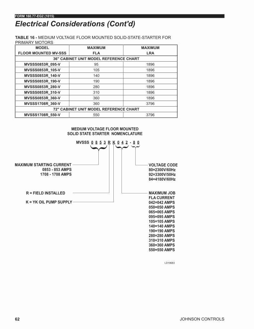
JOHNSON CONTROLS
FORM 160.77-EG2 (1015)
62
Electrical Considerations (Cont'd)
{ { {
TABLE 16 - MEDIUM VOLTAGE FLOOR MOUNTED SOLID-STATE-STARTER FOR PRIMARY MOTORS
MODEL FLOOR MOUNTED MV-SSS
MAXIMUMFLA
MAXIMUMLRA
36" CABINET UNIT MODEL REFERENCE CHARTMVSSS0853R_095-V 95 1896MVSSS0853R_105-V 105 1896MVSSS0853R_140-V 140 1896MVSSS0853R_190-V 190 1896MVSSS0853R_280-V 280 1896MVSSS0853R_310-V 310 1896MVSSS0853R_360-V 360 1896MVSSS1708R_360-V 360 3796
72" CABINET UNIT MODEL REFERENCE CHARTMVSSS1708R_550-V 550 3796
LD19683

FORM 160.77-EG2 (1015)
JOHNSON CONTROLS 63
Electrical Considerations (Cont'd)TABLE 17 - LOW VOLTAGE UNIT MOUNTED SOLID-STATE-STARTER FOR ECONOMIZER MOTORSMODEL
SSS-MAXIMUM
LRAMINIMUM
FLAMAXIMUM
FLARATED
VOLTAGEACTUAL
VOLTAGE PHASE HZ
7L-40B 1556 35 260 380 380 3 607L-46B 1556 35 260 460 440/460/480 3 607L-50B 1556 35 260 400 380/400/415 3 507L-58B 1556 35 260 575 575 3 60
14L-40B 3111 65 510 380 380 3 6014L-46B 3111 65 510 460 440/460/480 3 6014L-50B 3111 65 510 400 380/400/415 3 5014L-58B 3111 65 510 575 575 3 60

JOHNSON CONTROLS
FORM 160.77-EG2 (1015)
64
Dimensions
NOTES: 1. All dimensions are approximate. Certified dimensions are available on request. 2. Water nozzles can be located on either end of unit. Add 1/2” (13mm) to nozzle length for flanges connec-
tions. 3. To determine overall height, add dimension “M” for the appropriate isolator type. 4. Use of motors with motor hoods may increase overall unit dimensions. 5. Tubesheets are provided with jacking point notches
EVAPORATOR
CONDENSER
AOVERALL WIDTH OF UNIT
DC
F
ME
34-7/8”(885)
BOVERALL
HEIGHT OF UNIT
CONTROLPANEL
4’ 3”(1295)
11’ 1/4”(3359)
22’ 1/4”(6712)
25’ 9-1/4”(8520)
OVERALL LENGTH
PRIMARYMOTOR
PRIMARYCOMPRESSOR
ECONOMIZERMOTOR
ECONOMIZERCOMPRESSOR
LD18788a

FORM 160.77-EG2 (1015)
JOHNSON CONTROLS 65
Dimensions (Cont'd)
ADDITIONAL OPERATING HEIGHT CLEARANCE TO FLOOR INCHES (mm)TYPE OF CHILLER MOUNTING MNEOPRENE PAD ISOLATORS 1-3/4" (44)SPRING ISOLATORS 1" DEFLECTION 1" (25)DIRECT MOUNT 3/4" (19)
EVAPORATOR - CONDENSER SHELL CODES FT-IN (mm)B-B C-C
A12’-3 1/4”
(3753)13’-3 1/4”
(4058)
B12’-10 3/8”
(3922)13’-6 3/8”
(4125)
C2’-10”(864)
3’-1 1/2”(954)
D2’-7 1/2”
(802)2’-10”(864)
E5’-8”
(1728)6’-3”
(1905)
F10’-11”(3328)
11’-11”(3633)

JOHNSON CONTROLS
FORM 160.77-EG2 (1015)
66
AA
C C
BB
DD
C C
EEEEEEEE
BB
DD
C C
LD07173aEN
EVAPORATORS – COMPACT WATER BOXES
1 PASSIN OUTA HH A
2 PASS
IN OUTD CE BL KM J
3 PASSIN OUTG NP F
Dimensions (Cont'd)

FORM 160.77-EG2 (1015)
JOHNSON CONTROLS 67
COMPACT WATER BOXES - 150 PSI (10 bar)
EVAPORATOR SHELL CODE
NOZZLE PIPE SIZE(IN) EVAPORATOR NOZZLE DIMENSIONS FT-IN (mm)NO. OF PASSES 1-PASS 2-PASS 3-PASS
1 2 3 C AA5 BB5 DD5 EE BB5 DD5
B- 20” 18” 14”2’-10”(864)
3’-7 1/4”(1099)
2’-5 1/4”(743)
4’-11 3/4”(1519)
0’-10 1/2”(268)
2’-1 3/4”(656)
5’-3” 1/4”(1607)
C- 20” 18” 14”3’-1 1/2”
(954)3’-11 3/4”
(1214)2’-9 3/4”
(859)5’-4”
(1626)0’-11”(280)
2’-9 3/4”(859)
5’-9” 7/8”(1776)
EVAPORATORS – COMPACT WATER BOXES
Dimensions (Cont'd)
NOTES: 1. Standard water nozzles are furnished as welding stub-outs with ANSI/AWWA C-606 grooves, allowing the option of welding, flanges,
or use of ANSI/AWWA C-606 couplings. Factory-installed, class 150 (ANSI B16.5, round slip-on, forged carbon steel with 1/16” (2mm) raised face), water flanged nozzles are optional (add 1/2” (13mm) to nozzle length). Companion flanges, nuts, bolts, and gaskets are not furnished.
2. One-, two- and three-pass nozzle arrangements are available only in pairs shown and for all shell codes. Any pair of evaporator nozzles may be used in combination with any pair of condenser nozzles.
3. Evaporator and condenser water must enter the water box through the bottom connection to achieve rated performance. 4. Connected piping should allow for removal of compact water boxes for tube access and cleaning. 5. Add dimension “M” as shown in ADDITIONAL OPERATING HEIGHT CLEARANCE TO FLOOR INCHES (mm) on page 65 for the ap-
propriate isolator type. 6. Standard 150 PSI (10 bar) design pressure boxes shown.

JOHNSON CONTROLS
FORM 160.77-EG2 (1015)
68
C
M D D M
C
BEBE
DM D M
BE
D M
BE
DM
LD07131aEN
1 PASSIN OUTP QQ P
2 PASSIN OUTR ST U
3 PASSIN OUTV YX W
CONDENSERS – COMPACT WATER BOXES
Dimensions (Cont'd)

FORM 160.77-EG2 (1015)
JOHNSON CONTROLS 69
NOTES: 1. Standard water nozzles are furnished as welding stub-outs with ANSI/AWWA C-606 grooves, allowing the option of welding, flanges, or
use of ANSI/AWWA C-606 couplings. Factory-installed, class 150 (ANSI B16.5, round slip-on, forged carbon steel with 1/16” (2mm) raised face), water flanged nozzles are optional (add 1/2” to nozzle length). Companion flanges, nuts, bolts, and gaskets are not furnished.
2. One-, two- and three-pass nozzle arrangements are available only in pairs shown and for all shell codes. Any pair of evaporator nozzles may be used in combination with any pair of condenser nozzles.
3. Evaporator and condenser water must enter the water box through the bottom connection to achieve rated performance. 4. Connected piping should allow for removal of compact water boxes for tube access and cleaning. 5. Add dimension “M” as shown in ADDITIONAL OPERATING HEIGHT CLEARANCE TO FLOOR INCHES (mm) on page 65 for the ap-
propriate isolator type. 6. Standard 150 PSI (10 bar) design pressure boxes shown.
COMPACT WATER BOXES - 150 PSI (10 bar)
CONDENSER SHELL CODE
NOZZLE PIPE SIZE(IN) CONDENSER NOZZLE DIMENSIONS FT-IN (mm)NO. OF PASSES 1-PASS 2-PASS 3-PASS
1 2 3 D C5 B5 E5 B5 E5
B- 24" 18" 16"2’-7 1/2”
(802)4’-6 5/8”(1389)
3’-4 1/8”(1020)
5’-9 1/8”(1756)
3’-4 1/8”(943)
5’-9 1/8”(1756)
C- 24" 20" 16"2’-10”(864)
4’-8 3/8”(1432)
3’-4 3/8”(1026)
6’-0 3/8”(1839)
3’-4 3/8”(1026)
6’-0 3/8”(1839)
CONDENSERS – COMPACT WATER BOXES
Dimensions (Cont'd)

JOHNSON CONTROLS
FORM 160.77-EG2 (1015)
70
EVAPORATORS – COMPACT WATER BOXES
WATERBOX DIMENSIONS FT-IN (mm)EVAPORATOR SHELL CODE
A B
B- 2’-0 5/8” (627)
1’-4 3/4” (427)
C- 2’-1 3/4” (656)
1’-5 3/4” (452)
Dimensions (Cont'd)
A A
A A
AB
LD07619a
ONE PASS
THREE PASS
TWO PASS

FORM 160.77-EG2 (1015)
JOHNSON CONTROLS 71
CONDENSERS – COMPACT WATER BOXES
WATERBOX DIMENSIONS FT-IN (mm)CONDENSERSHELL CODE
A B
B- 1’-10 1/2” (573)
1’-3 3/8” (391)
C- 1’-11 5/8” (602)
1’-4 3/8” (416)
Dimensions (Cont'd)
A A
A A
AB
LD07619a
ONE PASS
THREE PASS
TWO PASS

JOHNSON CONTROLS
FORM 160.77-EG2 (1015)
72
C C
C
C C C
C
CC
R
RR
R
P P
Q Q
Q
Q Q
P
PP
P
LD07175a
EVAPORATORS – MARINE WATER BOXES
1 PASS 2 PASS 3 PASSIN OUT IN OUT IN OUT1 6 2 3 5 106 1 7 8 9 4
Dimensions (Cont'd)

FORM 160.77-EG2 (1015)
JOHNSON CONTROLS 73
MARINE WATER BOXES - 150 PSI (10 bar)
EVAPORATOR SHELL CODE
NOZZLE PIPE SIZE EVAPORATORS NOZZLE DIMENSIONS FT-IN (mm)NO. OF PASSES 1-PASS 2-PASS 3-PASS1 2 3 C P5 P5 Q5 R P5 Q5 R
B- 20” 18” 14”2’-10” (864)
6’-9 5/8” (2075)
6’-9 5/8” (2075)
1’-7 1/2” (497)
3’- 0 1/8” (918)
6’-9 5/8” (2075)
1’-7 1/2” (497)
3’-0 1/8” (918)
C- 20” 18” 14”3’-1 1/2”
(954)7’ 5 1/8” (2264)
7’ 5 1/8” (2264)
2’ - 1” (635)
3’- 0 3/4” (935)
7’ 5 1/8” (2264)
2’ - 1” (635)
3’-0 3/4” (935)
NOTES: 1. All dimensions are approximate. Certified dimensions are available upon request. 2. Standard water nozzles are Schedule 40 pipe size, furnished as welding stub-outs with ANSI/AWWA C-606 grooves, allowing the option
of welding, flanges, or use of ANSI/AWWA C-606 couplings. Factory-installed, class 150 (ANSI B16.5, round slip-on, forged carbon steel with 1/16" (2 mm) raised face), water flanged nozzles are optional (add 1/2" (13 mm) to nozzle length). Companion flanges, nuts, bolts, and gaskets are not furnished.
3. One-, two-, and three-pass nozzle arrangements are available only in pairs shown and for all shell codes. Any pair of evaporator nozzles may be used in combination with any pair of condenser nozzles. Compact water boxes on one heat exchanger may be used with Marine Water Boxes on the other heat exchanger.
4. Condenser water must enter the water box through the bottom connection for proper operation of the sub-cooler to achieve rated perfor-mance.
EVAPORATORS – MARINE WATER BOXES
Dimensions (Cont'd)

JOHNSON CONTROLS
FORM 160.77-EG2 (1015)
74
1 PASS 2 PASS 3 PASSIN OUT IN OUT IN OUT11 16 12 13 15 2016 11 17 18 19 14
LD07178a
CONDENSERS – MARINE WATER BOXES
Dimensions (Cont'd)
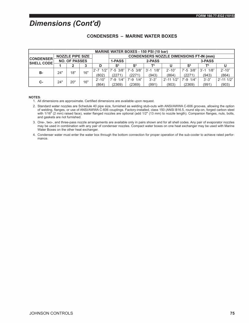
FORM 160.77-EG2 (1015)
JOHNSON CONTROLS 75
MARINE WATER BOXES - 150 PSI (10 bar)
CONDENSER SHELL CODE
NOZZLE PIPE SIZE CONDENSERS NOZZLE DIMENSIONS FT-IN (mm)NO. OF PASSES 1-PASS 2-PASS 3-PASS1 2 3 D S5 S5 T5 U S5 T5 U
B- 24" 18" 16"2’-7 1/2”
(802)7’-5 3/8” (2271)
7’-5 3/8” (2271)
3’-1 1/8” (943)
2’-10” (864)
7’-5 3/8” (2271)
3’-1 1/8” (943)
2’-10” (864)
C- 24" 20" 16"2’-10” (864)
7’-9 1/4” (2369)
7’-9 1/4” (2369)
3’-3” (991)
2’-11 1/2” (903)
7’-9 1/4” (2369)
3’-3” (991)
2’-11 1/2” (903)
CONDENSERS – MARINE WATER BOXES
NOTES: 1. All dimensions are approximate. Certified dimensions are available upon request. 2. Standard water nozzles are Schedule 40 pipe size, furnished as welding stub-outs with ANSI/AWWA C-606 grooves, allowing the option
of welding, flanges, or use of ANSI/AWWA C-606 couplings. Factory-installed, class 150 (ANSI B16.5, round slip-on, forged carbon steel with 1/16" (2 mm) raised face), water flanged nozzles are optional (add 1/2" (13 mm) to nozzle length). Companion flanges, nuts, bolts, and gaskets are not furnished.
3. One-, two-, and three-pass nozzle arrangements are available only in pairs shown and for all shell codes. Any pair of evaporator nozzles may be used in combination with any pair of condenser nozzles. Compact water boxes on one heat exchanger may be used with Marine Water Boxes on the other heat exchanger.
4. Condenser water must enter the water box through the bottom connection for proper operation of the sub-cooler to achieve rated perfor-mance.
Dimensions (Cont'd)

JOHNSON CONTROLS
FORM 160.77-EG2 (1015)
76
EVAPORATORS – MARINE WATER BOXES
EVAPORATORSHELL CODE
PASSEVAPORATOR NOZZLE
DIMENSIONS FT-IN (mm)A B C
B- 12’-8”(813)
1’-2 5/8”(373)
N/A
B- 22’-6”(762)
1’-1 5/8”(348)
1’-2 1/2”(370)
B- 32’-6”(762)
1’-1 5/8”(348)
N/A
C- 12’-9”(839)
1’-2 5/8”(373)
N/A
C- 22’-6”(762)
1’-1 5/8”(348)
1’-2 5/8”(370)
C- 32’-6”(762)
1’-1 5/8”(348)
N/A
Dimensions (Cont'd)
BA C
LD19211
NOTES: 1. All dimensions are approximate. Certified dimensions are available upon request. 2. Standard water nozzles are Schedule 40 pipe size, furnished as welding stub-outs with ANSI/AWWA
C-606 grooves, allowing the option of welding, flanges, or use of ANSI/AWWA C-606 couplings. Factory-installed, class 150 (ANSI B16.5, round slip-on, forged carbon steel with 1/16" (2 mm) raised face), water flanged nozzles are optional (add 1/2" (13 mm) to nozzle length). Companion flanges, nuts, bolts, and gaskets are not furnished.
3. One-, two-, and three-pass nozzle arrangements are available only in pairs shown and for all shell codes. Any pair of evaporator nozzles may be used in combination with any pair of condenser nozzles. Compact water boxes on one heat exchanger may be used with Marine Water Boxes on the other heat exchanger.
4. Condenser water must enter the water box through the bottom connection for proper operation of the sub-cooler to achieve rated performance.

FORM 160.77-EG2 (1015)
JOHNSON CONTROLS 77
CONDENSERS – MARINE WATER BOXES
CONDENSERSHELL CODE
PASSCONDENSER NOZZLE
DIMENSIONS FT-IN (mm)A B C
B- 13'
(915)1'-4 1/2"
(421)N/A
B- 22'-6"(762)
1'-1 1/2"(344)
11"(280)
B- 32'-6"(762)
1'-1 1/2"(344)
N/A
C- 13'
(915)1'-4 5/8"
(424)N/A
C- 22'-8"(813)
1'-2 5/8"(373)
11"(280)
C- 32'-6"(762)
1'-2"(356)
N/A
Dimensions (Cont'd)
BA C
LD19211
NOTES: 1. All dimensions are approximate. Certified dimensions are available upon request. 2. Standard water nozzles are Schedule 40 pipe size, furnished as welding stub-outs with ANSI/AWWA
C-606 grooves, allowing the option of welding, flanges, or use of ANSI/AWWA C-606 couplings. Factory-installed, class 150 (ANSI B16.5, round slip-on, forged carbon steel with 1/16" (2 mm) raised face), water flanged nozzles are optional (add 1/2" (13 mm) to nozzle length). Companion flanges, nuts, bolts, and gaskets are not furnished.
3. One-, two-, and three-pass nozzle arrangements are available only in pairs shown and for all shell codes. Any pair of evaporator nozzles may be used in combination with any pair of condenser nozzles. Compact water boxes on one heat exchanger may be used with Marine Water Boxes on the other heat exchanger.
4. Condenser water must enter the water box through the bottom connection for proper operation of the sub-cooler to achieve rated performance.
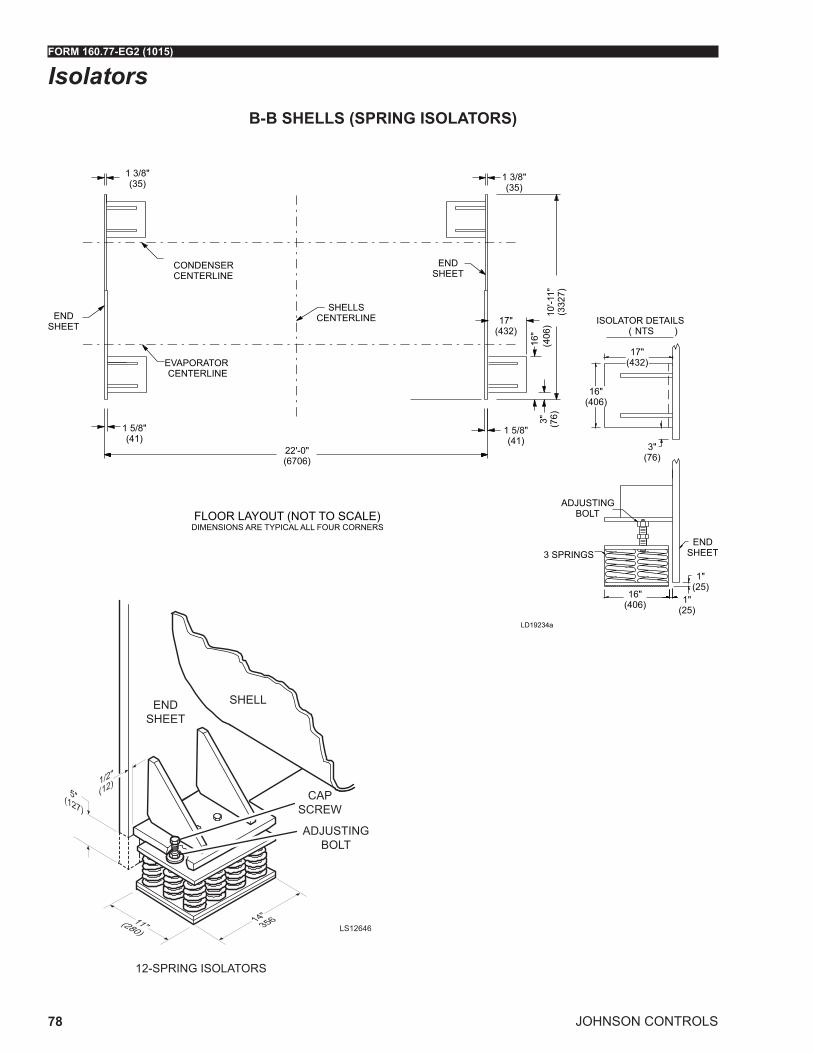
JOHNSON CONTROLS
FORM 160.77-EG2 (1015)
78
Isolators
FLOOR LAYOUT (NOT TO SCALE)DIMENSIONS ARE TYPICAL ALL FOUR CORNERS
1 3/8"(35)
ENDSHEET
CONDENSERCENTERLINE
EVAPORATORCENTERLINE
1 5/8"(41)
22'-0"(6706)
ENDSHEET
SHELLSCENTERLINE
1 3/8"(35)
16"
(406
)3" (76)
1 5/8"(41)
17"(432)
10'-1
1"(3
327)
ISOLATOR DETAILS( NTS )
16"(406)
17"(432)
3"(76)
ADJUSTINGBOLT
3 SPRINGSEND
SHEET
16"(406) 1"
(25)
1"(25)
LD19234a
SHELL
12-SPRING ISOLATORS
ENDSHEET
CAP SCREW
ADJUSTING BOLT
LS12646
B-B SHELLS (SPRING ISOLATORS)

FORM 160.77-EG2 (1015)
JOHNSON CONTROLS 79
Isolators (Cont'd)
ISOLATORDETAILS11"
(279)10"
(254)
10"(254)
9"(229)
1/2"(13)
1/2"(13)
ISOLATOR TO BE CENTEREDUNDER SUPPORT FOOT
1" (254) DEFLECTEDHEIGHT
RUBBER PAD
STEEL PLATE3/8"(10)
ENDSHEET
1 3/8"(35)
CONDENSERCENTERLINE
EVAPORATORCENTERLINE
1 5/8"(41)
22'-0"(6706)
FLOOR LAYOUT (NOT TO SCALE)DIMENSIONS ARE TYPICAL FOR ALL EIGHT PADS
SUPPORTFOOT
10"
(254
)4"
(102
)
1 3/8"(35)
ENDSHEET
4"(1
02)
3"(76)8"
(203)7/8" DIA.
HOLE
5"(1
27)
1"(25)1 5/8"(41)
5'-8
"(1
727)
10'-1
1"(3
327)
SHELLSCENTERLINE
LD19235
SHELL
END SHEETDIA. HOLE
LD12642
B-B SHELLS (NEOPRENE PAD ISOLATORS)

JOHNSON CONTROLS
FORM 160.77-EG2 (1015)
80
Isolators (Cont'd)
FLOOR LAYOUT (NOT TO SCALE)DIMENSIONS ARE TYPICAL ALL FOUR CORNERS
1 3/8"(35)
ENDSHEET
CONDENSERCENTERLINE
EVAPORATORCENTERLINE
1 5/8"(41)
22'-0"(6706)
ENDSHEET
SHELLSCENTERLINE
1 3/8"(35)
16"
(406
)3" (76)
1 5/8"(41)
17"(432)
11'-1
1"(3
632)
ISOLATOR DETAILS( NTS )
16"(406)
17"(432)
3"(76)
ADJUSTINGBOLT
3 SPRINGSEND
SHEET
16"(406) 1"
(25)
1"(25)
LD19234b
SHELL
12-SPRING ISOLATORS
ENDSHEET
CAP SCREW
ADJUSTING BOLT
LS12646
C-C SHELLS (SPRING ISOLATORS)
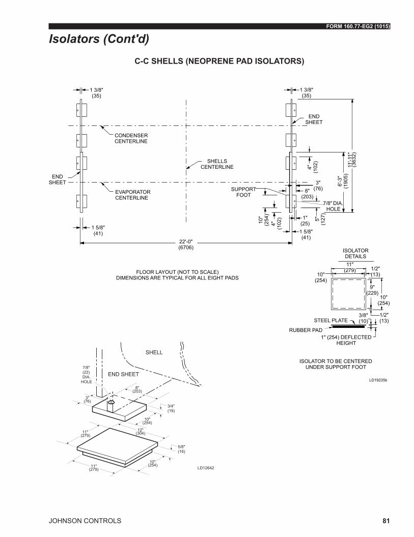
FORM 160.77-EG2 (1015)
JOHNSON CONTROLS 81
Isolators (Cont'd)
ISOLATORDETAILS11"
(279)10"
(254)
10"(254)
9"(229)
1/2"(13)
1/2"(13)
ISOLATOR TO BE CENTEREDUNDER SUPPORT FOOT
1" (254) DEFLECTEDHEIGHT
RUBBER PAD
STEEL PLATE3/8"(10)
ENDSHEET
1 3/8"(35)
CONDENSERCENTERLINE
EVAPORATORCENTERLINE
1 5/8"(41)
22'-0"(6706)
FLOOR LAYOUT (NOT TO SCALE)DIMENSIONS ARE TYPICAL FOR ALL EIGHT PADS
SUPPORTFOOT
10"
(254
)4"
(102
)
1 3/8"(35)
ENDSHEET
4"(1
02)
3"(76)8"
(203)7/8" DIA.
HOLE
5"(1
27)
1"(25)1 5/8"(41)
6'-3
"(1
905)
11'-1
1"(3
632)
SHELLSCENTERLINE
LD19235b
SHELL
END SHEETDIA. HOLE
LD12642
C-C SHELLS (NEOPRENE PAD ISOLATORS)

JOHNSON CONTROLS
FORM 160.77-EG2 (1015)
82
TABLE 13 - APPROXIMATE UNIT WEIGHT INCLUDING MOTOR
SHELLS SHIPPING WEIGHT LBS (kg)
OPERATING WEIGHT LBS (kg)
EST REFRIGERANT CHARGE LBS (kg)
BB-B 89953 (40762) 115154 (52181) 10968 (4970) BC-B 91597 (41507) 116953 (52996) 10382 (4704) BD-B 93415 (42330) 118943 (53898) 9733 (4410) B5-B 88072 (39909) 113646 (51498) 11248 (5097) B6-B 89083 (40367) 114836 (52037) 10784 (4887) B7-B 89884 (40730) 116380 (52737) 10417 (4720) B8-B 90706 (41103) 116752 (52905) 10032 (4546) CJ-C 91667 (41538) 119365 (54089) 12225 (5539) CK-C 92769 (42038) 120574 (54637) 11819 (5356) CL-C 93797 (42504) 121702 (55148) 11440 (5184) C6-C 87325 (39571) 115279 (52238) 13282 (6019) C7-C 88583 (40141) 116770 (52914) 12683 (5747) C8-C 89929 (40751) 118367 (53637) 12041 (5456) C9-C 90927 (41203) 119550 (54173) 11564 (5240)
TABLE 14 - EVAPORATOR WATER BOX WEIGHTS (TO BE ADDED TO STANDARD UNIT WEIGHTS AS SHOWN ON TABLE 13)
SHELLSSHIPPING WEIGHT INCREASE
LBS (kg)OPERATING WEIGHT INCREASE
LBS (kg)1-PASS 2-PASS 3-PASS 1-PASS 2-PASS 3-PASS
B-B4800
(2180)2700
(1230)4910
(2230)8520
(3870)4520
(2050)8190
(3720)
C-C7090
(3220)3660
(1660)7240
(3300)11550(5250)
5510(2500)
11250(5110)
TABLE 15 - CONDENSER WATER BOX WEIGHTS (TO BE ADDED TO STANDARD UNIT WEIGHTS AS SHOWN ON TABLE 13)
SHELLSSHIPPING WEIGHT INCREASE LBS (kg)
OPERATING WEIGHT INCREASE LBS (kg)
1-PASS 2-PASS 3-PASS 1-PASS 2-PASS 3-PASS
B-B5200
(2360)2600
(1180)5200
(2360)9160
(4160)4010
(1820)8220
(3730)
C-C5840
(2650)2960
(1340)5380
(2450)9900
(4500)4650
(2110)8100
(3680)
Weights

FORM 160.77-EG2 (1015)
JOHNSON CONTROLS 83
Guide Specifications
Furnish and install where indicated on the drawings____ YORK YK-EP Centrifugal Liquid Chilling Unit(s). Each unit shall produce a capacity ____ of tons, cooling ____ GPM of ___ from ____ °F to ____ °F when supplied with ____ GPM of condenser water at ____ °F. Power input shall not exceed ____ kW with an IPLV (NPLV) of ____ . The evaporator shall be selected for___ fouling factor and a maximum liquid pressure drop of ____ ft. Water side shall be designed for 150 psig working pressure. The condenser shall be selected for ____ fouling factor and maximum liquid pressure drop of ____ ft. Waterside shall be designed for 150 psig working pressure. Power shall be supplied to the primary compres-sor motor at ____ volts – 3-phase – (60) Hertz and to the economizer compressor motor solid-state-starter at ____ volts – 3-phase – (60) Hertz. Power also shall be supplied to the Control Panel – For remote starters or medium voltage variable speed drive a 115 volt, single phase, 60 Hertz 2 kVa power supply must be furnished at the starter. For chillers with unit mounted united mounted solid-state-starter, the variable speed oil pump power panel will not require an additional control power transformer, but will be included in the YORK furnished Primary starter. For chillers without a unit-mounted primary starter, a 3-phase supply will be required for the auxiliary power (heater and oil pump).The econo-mizer compressor auxiliary power is always sourced from the economizer starter which is unit-mounted.
or
Furnish and install where indicated on the drawings ___ YORK YK-EP Centrifugal Liquid Chilling Unit(s). Each unit shall produce a capacity of ____ kW, cooling ____ l/s of ____ from ____ °C to ____ °C when supplied with ____ l/s of condenser water at ____°C. Power input shall not exceed ____ kW with an IPLV (NPLV) of ____. The evaporator shall be selected for ____m2 C/W fouling factor and maximum liquid pressure drop of ____kPa. Waterside shall be designed for 10.3 barg working pressure. The condenser shall be se-lected for ____ fouling factor and maximum liquid pressure drop of ____ kPa. Waterside shall be designed for 10.3 barg working pressure. Power shall be supplied to the primary compressor motor at ____ volts – 3-phase – (50) Hertz and to the economizer compres-sor motor solid-state-starter at ____ volts – 3-phase – (50) Hertz. Power also shall be sup-plied to the Control Panel – For remote starters or medium voltage variable speed drive a 115 volt, single phase, 50 Hertz 2 kVa power supply must be furnished at the starter. For chillers with unit mounted united mounted solid-state-starter, the variable speed oil pump power panel will not require an additional control power transformer, but will be included in the YORK furnished Primary starter. For chillers without a unit-mounted primary starter, a 3-phase supply will be required for the auxiliary power (heater and oil pump).The econo-mizer compressor auxiliary power is always sourced from the economizer starter which is unit-mounted.
COMPRESSORS
Two centrifugal compressors shall be provided, operating partially in parallel and dis-charging to a common condenser on the chiller. Check valves will be supplied on the discharge economizer compressor to control refrigerant flow during single compressor operation.

JOHNSON CONTROLS
FORM 160.77-EG2 (1015)
84
Guide Specifications (Cont'd)Each compressor shall be a single-stage centrifugal type, powered by an open-drive elec-tric motor. The housing shall be fully accessible with vertical circular joints, with the com-plete operating assembly removable from the compressor and scroll housing. Castings on both the primary and economizer compressors shall be designed for a minimum 235 PSIG working pressure and hydrostatically pressure tested at a minimum of 352 PSIG. The rotor assembly shall consist of a heat-treated alloy steel drive shaft and impeller shaft with a cast aluminum, fully shrouded impeller. The impeller shall be designed for balanced thrust, dynamically balanced and over-speed tested for smooth, vibration-free operation. Insert-type journal and thrust bearings shall be fabricated of aluminum alloy, precision bored and axially grooved.
Internal single helical gears with crowned teeth shall be designed so that more than one tooth is in contact at all times to provide even load distribution and quiet operation. Each gear shall be individually mounted in its own journal and thrust bearings to isolate it from impeller and motor forces. Shaft seal shall be provided in double bellows, double-seal, cartridge type. A gravity-fed oil reservoir shall be built into the top of the compressor to provide lubrication during coast-down in the event of a power failure.
Fixed Speed Drive - Capacity control shall be achieved by use of pre-rotation vanes to provide fully modulating control from full load to minimum load.
Variable Speed Drive - Capacity control shall be accomplished by the Adaptive Capacity Control (ACC), providing optimal relationship between compressor speed and inlet pre-rotation vane position for maximum energy efficiency. Control shall automatically compen-sate for adverse operating conditions, such as fouled tubes, and adjust to prior operation after correction of these conditions.
The unit shall be capable of continuous, reliable operation with low ECWT at all load conditions as outlined on the equipment schedule. An external electric actuator shall au-tomatically control pre-rotation vane position.
LUBRICATION SYSTEM
Lubrication oil shall be force-fed to all compressor bearings, gears, and rotating surfaces by an external variable speed oil pump. The oil pumps shall vary oil flow to the com-pressor based on operating and stand-by conditions, ensuring adequate lubrication at all times. The oil pumps shall operate prior to start-up, during compressor operation and dur-ing coastdown. Compressors shall each have an auxiliary reservoir to provide lubrication during coastdown in the event of a power failure.
An oil reservoir, separate from the compressor, shall contain the two submersible 2 HP oil pumps and a oil heaters, thermostatically controlled to remove refrigerant from the oil. The oil reservoir shall be listed as part of the chiller by a nationally recognized testing labora-tory and shall be factory air strength tested at 1.1 times design working pressure.
Oil shall be filtered by an externally mounted 1/2 micron replaceable cartridge oil filter equipped with service valves. Oil cooling shall be done via a refrigerant cooled oil cooler, with all piping factory-installed. Oil side of the oil cooler shall be provided with service valves.
An automatic oil return system to recover any oil that may have migrated to the evaporator shall be provided. Oil piping shall be completely factory-installed and tested.

FORM 160.77-EG2 (1015)
JOHNSON CONTROLS 85
Guide Specifications (Cont'd)MOTOR DRIVELINE
Each compressor motor shall be an open drip-proof, squirrel cage, induction type operat-ing at 3570 rpm (2975 rpm for 50 Hz operation).
Each open motor shall be provided with a D-flange, bolted to a cast iron adaptor mounted on the compressor to allow the motor to be rigidly coupled to the compressor to provide factory alignment of motor and compressor shafts.
Each motor drive shaft shall be directly connected to its compressor shaft with a flex-ible disc coupling. The coupling shall have all metal construction with no wearing parts to assure long life, and no lubrication requirements to provide low maintenance. A large steel terminal box with gasketed front access cover shall be provided for field-connected conduit.
EVAPORATOR
Evaporator shall be of the shell-and-tube, flooded type designed for a minimum of 180 PSIG (1241 kPa) working pressure on the refrigerant side. Shell shall be fabricated from rolled carbon steel plates with fusion welded seams, carbon steel tube sheets, drilled and reamed to accommodate the tubes, and intermediate tube supports spaced no more than four feet apart. The refrigerant side of each shell is designed, tested and stamped in ac-cordance with ASME Boiler and Pressure Vessel Code, Section VIII – Division I, or other pressure vessel code as appropriate.
Heat exchanger tubes shall be high-efficiency, externally and internally enhanced type. Tubes shall utilize the “skip-fin” design, providing a smooth internal and external surface at each intermediate tube support. This provides extra wall thickness and non-work hard-ened copper at the support location, extending the life of the heat exchangers. If skip-fin tubes are not used, minimum tube wall thickness shall be 0.035” (0.889 mm). Each tube shall be roller expanded into the tube sheets providing a leak-proof seal, and be individu-ally replaceable. Water velocity through the tubes shall not exceed 12 ft./sec. (3.65 m/sec). A liquid level sight glass shall be provided on the side of the shell to aid in deter-mining proper refrigerant charge and to check condition of the refrigerant charge. Alumi-num mesh eliminators shall be located above the tube bundle to prevent liquid refrigerant carryover to the compressor. The evaporator shall have a refrigerant relief device sized to meet the requirements of the ASHRAE 15 Safety Code for Mechanical Refrigeration.
Water boxes shall be removable to permit tube cleaning and replacement. Stub-out water connections having ANSI/AWWA C-606 grooves shall be provided. Water boxes shall be designed for 150 PSIG (1034 kPa) design working pressure and be tested at 225 PSIG (1551 kPa). Vent and drain connections with plugs shall be provided on each water box. Low flow protection shall be provided by a thermal-type flow sensor, factory mounted in the water nozzle connection and wired to the chiller panel.
CONDENSER
Condenser shall be of the shell-and-tube type, designed for a minimum of 235 psig (16.2 barg) working pressure on the refrigerant side. Shell shall be fabricated from rolled carbon steel plates with fusion welded seams. Carbon steel tube sheets, drilled and reamed to accommodate the tubes, are welded to the end of each shell. Intermediate tube supports are drilled and reamed to eliminate sharp edges, fabricated from carbon steel plates. The refrigerant side of each shell is designed, tested and stamped in accordance with ASME Boiler and Pressure Vessel Code, Section VIII – Division I, or other pressure vessel code as appropriate.

JOHNSON CONTROLS
FORM 160.77-EG2 (1015)
86
Guide Specifications (Cont'd)Heat exchanger tubes shall be high efficiency, externally and internally enhanced type. Tubes shall utilize the “skip-fin” design, providing a smooth internal and external surface at each intermediate tube support.
This provides extra wall thickness and non-work hardened copper at the support loca-tion, extending the life of the heat exchangers. If skip-fin tubes are not used, minimum tube wall thickness shall be 0.035” (~1 mm). Each tube shall be roller expanded into the tube sheets providing a leak-proof seal, and be individually replaceable. Water velocity through the tubes shall not exceed 12 ft./sec. (3.7 m/sec.). A liquid level sight glass shall be provided on the side of the shell to aid in determining proper refrigerant charge and to check condition of the refrigerant charge. The condenser shall have dual refrigerant relief devices; each sized to meet the requirements of the ASHRAE 15 Safety Code for Me-chanical Refrigeration. Arrangement shall allow either valve to be isolated and replaced without removing the unit refrigerant charge.
The condenser shall be provided with positive shutoff valves in the compressor discharge line to the condenser and in the liquid line leaving the condenser. This will allow pump-down and storage of the refrigerant charge in the condenser. Due to the possibility of not seating properly, check valves are not acceptable for isolation purposes. If a check valve is used, a positive shutoff valve must be provided in series with the check valve.
Water boxes shall be removable to permit tube cleaning and replacement. Stubout water connections having ANSI/AWWA C-606 grooves shall be provided. Water boxes shall be designed for 150 psig (10.3 barg) design working pressure and be tested at 225 psig (15.5 barg). Vent and drain connections with plugs shall be provided on each water box.
REFRIGERANT FLOW CONTROL
Refrigerant flow shall be controlled by a variable orifice. The variable orifice controls shall automatically adjust to maintain proper refrigerant level in the condenser, economizer, and evaporator. This shall be controlled by monitoring refrigerant level in the condenser and economizer, assuring optimal subcooler and economizer performance.
FLASH ECONOMIZER (INTERCOOLER)
A single stage, horizontal type, flash economizer (intercooler) shall be provided with in-ternally mounted baffles, liquid spray pipe, an externally mounted level transmitter and an external control valve.
CONTROL CENTER
General – The chiller shall be controlled by a single microprocessor based control cen-ter. The chiller control panel shall provide control of chiller operation and monitoring of chiller sensors, actuators, relays and switches. The chiller panel shall provide capacity control operation of the compressors, and shall provide cycling of primary compressor in response to load requirements.
Control Panel – The control panel shall include a 10.4 in. diagonal color liquid crystal dis-play (LCD) surrounded by "soft" keys which are redefined based on the screen displayed at that time. This shall be mounted in the middle of a keypad interface and installed in a locked enclosure. The screen shall detail all operations and parameters, using a graphical representation of the chiller and its major components. Panel verbiage shall be available in other languages as an option, with English always available. Data shall be displayed

FORM 160.77-EG2 (1015)
JOHNSON CONTROLS 87
Guide Specifications (Cont'd)in either English or Metric units. Smart Freeze Point Protection shall run the chiller at 36°F (2.2°C) leaving chilled water temperature, and not have nuisance trips on low water temperature. The sophisticated program and sensor shall monitor the chiller water tem-perature to prevent freeze up. The panel shall display countdown timer messages so the operator knows when functions are starting and stopping. Every programmable point shall have a pop up screen with the allowable ranges, so that the chiller cannot be programmed to operate outside of its design limits.
The chiller control panel shall also provide:
A. System operating information including:
• Entering and leaving chilled water temperature.
• Entering and leaving condenser water temperature.
• Evaporator and condenser saturation temperature.
• Differential oil pressure (both compressors).
• Percent motor current (both motors).
• Compressor discharge temperature (both compressors).
• Oil reservoir temperature.
• Compressor thrust bearing position (primary compressors).
• Chiller operating hours, and operating hours.
• Number of unit starts, and number of starts each compressor.
B. Local programming of setpoints through the universal keypad including:
• Leaving chilled water temperature.
• Percent current limit.
• Pull down demand limiting.
• Six week schedule for starting and stopping the chiller, pumps and tower.
• Remote reset temperature range.
C. Status messages indicating: System ready to start
• System running.
• System coast down.
• System safety shutdown – manual restart.
• System cycling shutdown – auto restart.
• System prelube.
• Start inhibit.
D. The text displayed within the system status and system details field shall be displayed as color coded message to indicate severity: red for safety fault, orange for cycling faults, yellow for warnings, and green for normal messages.

JOHNSON CONTROLS
FORM 160.77-EG2 (1015)
88
E. Safety shutdowns enunciated through the display and the status bar, and consist of system status, system details, day, time, cause of shutdown, and type of restart re-quired. Safety shutdowns shall include:
• Evaporator – low pressure.
• Evaporator – transducer or leaving liquid probe.
• Evaporator – transducer or temperature sensor.
• Discharge – high pressure contacts open (each compressor).
• Condenser – high pressure.
• Condenser – pressure transducer out of range.
• Auxiliary safety – contacts closed.
• Discharge – high temperature (each compressor).
• Discharge – low temperature (each compressor).
• Oil – high temperature.
• Oil – low differential pressure (each compressor).
• Oil – high differential pressure (each compressor).
• Oil – sump pressure transducer out of range.
• Oil – differential pressure calibration (each compressor).
• Oil – variable speed pump – pressure setpoint not achieved (two).
• Thrust bearing – proximity probe clearance (primary compressor).
• Thrust bearing – proximity probe out of range (primary compressor).
• Thrust bearing – proximity probe uncalibrated (primary compressor).
• Watchdog – software reboot.
• Surge detection – excess surge.
F. Cycling shutdowns enunciated through the display and the status bar, and consists of system status, system details, day, time, cause of shutdown, and type of restart required. Cycling shutdowns shall include:
• Multi unit cycling – contacts open.
• System cycling – contacts open.
• Oil – low temperature differential.
• Oil – low temperature.
• Control panel – power failure.
• Leaving chilled liquid – low temperature.
• Leaving chilled liquid – flow switch open.
Guide Specifications (Cont'd)

FORM 160.77-EG2 (1015)
JOHNSON CONTROLS 89
• Motor controller – contacts open (each motor).
• Motor controller – loss of current (each motor).
• Power fault for each motor.
• Control panel – schedule.
• Proximity probe – low supply voltage. (Primary compressor)
• Oil – variable speed pump – drive contacts open (each pump).
G. Security access to prevent unauthorized change of setpoints, to allow local or remote control of the chiller, and to allow manual operation of the pre rotation vanes and oil pump. Access shall be through ID and password recognition, which is defined by three different levels of user competence: view, operator, and service.
H. Trending data with the ability to customize points of once every second to once every hour. The panel shall trend up to 6 different parameters from a list of over 140, without the need of an external monitoring system.
I. The operating program stored in non volatile memory (Flash) to eliminate reprogram-ming the chiller due to AC power failure. Programmed setpoints shall be retained in lithium battery backed RTC memory for a minimum of 11 years with power removed from the system.
J. A fused connection through a transformer mounted on the variable speed oil pump panel shall provide individual over current protected power for all controls.
K. A numbered terminal strip for all required field interlock wiring.
L. An RS-232 port to output current Status Report, History Reports, and Data Logging and a record of the last 10 cycling or safety shutdowns to a field supplied printer. Data logs to a printer or a computer at a set programmable interval. This data can be pre-programmed to print from 1 minute to 1 day.
M. The capability to interface with a building automation system to provide:
• Remote chiller start and stop.
• Remote leaving chiller liquid temperature adjust.
• Remote current limit setpoint adjust.
• Remote ready to start contacts.
• Safety shutdown contacts.
• Cycling shutdown contacts.
• Run contacts.
Guide Specifications (Cont'd)
JOHNSON CONTROLS
FORM 160.77-EG2 (1015)
90
MEDIUM VOLTAGE VSD STARTER (OPTION FOR PRIMARY COMPRESSOR)
The Variable Speed Drive will be remote floor mounted. It will vary the compressor motor speed by controlling the frequency and voltage of the electrical power to the motor. The capacity control logic shall automatically adjust motor speed and compressor pre-rotation vane position independently for maximum part-load efficiency by analyzing information fed to it by sensors located throughout the chiller.
Definitions
For the purpose of this Specification, the following definitions apply:
• VSD - Variable speed drive is a device that is used to vary the speed of a previously fixed speed motor.
• NPC - Neutral Point Clamp is an VSD topology that has the advantage of reducing the high line to neutral voltage that can occur in other traditional drive designs that can reach 2.7 to 3.3 times normal levels.
• PWM - Pulse Width Modulation is a method of controlling power devices to convert voltage levels. PWM is a popular method of control for converting DC voltage to AC voltage.
• IGBT- Insulated Gate Bipolar Transistor is a high speed electrical switching power device. It is very efficient requiring very low power for control circuits
• HCT - Hall Effect Current Transformer are used for detection of currents over a fre-quency range of DC to high frequency without direct contact or shunts.
• CPT- Control Power Transformer is typically used to power control circuits and relays for the VSD.
• FLA - Full Load Amps.
Components
The VSD shall consist of the following components:
• Incoming Disconnect.
• A 24 pulse input Isolation Transformer with Rectifier that limits electrical power sup-ply distortion.
• Frequency Converter/Inverter.
• VSD Protective System/Devices.
• Output filter or reactor (when required to limit reflected voltage).
• Output Disconnect(s) or bypass (when specified on Data Sheet).
• Diagnostics and Control Circuits.
• Two control power transformers, for the Control Center and for chiller oil pump opera-tion.
Guide Specifications (Cont'd)

FORM 160.77-EG2 (1015)
JOHNSON CONTROLS 91
Features
The following features will be provided:
• PWM type utilizing IGBT’s with a power factor of 0.95 or better at all loads and speeds.
• Door interlocked circuit breaker capable of being padlocked.
• UL listed ground fault protection.
• Over voltage and under voltage protection.
• 3-phase sensing motor over current protection.
• Single phase protection.
• Insensitive to phase rotation.
• Over temperature protection.
• 3-phase sensing motor over current protection.
• Single phase protection.
• Insensitive to phase rotation.
• Over temperature protection.
• Digital readout at the chiller unit control panel of output frequency, output voltage, 3-phase output current, input Kilowatts and Kilowatt-hours, self-diagnostic service parameters, Elapsed Time Meter.
• Separate meters for this information will not be acceptable.
General Design and Fabrication
The VSD inverter/chopper shall be of the pulse width modulated (PWM) Neutral Point Clamp (NPC) type. The output devices shall be Insulated Gate Bipolar Transistors (IG-BT’s) with a minimum voltage rating of 3300V. Use of lower rated devices is unacceptable due to the quantity of devices required in the design.
All components and material shall be new and of the latest field proven design and in current production. Obsolete components or components scheduled for immediate dis-continuation shall not be used.
The equipment shall be completely factory built, assembled, wired, and tested. When it is necessary to disassemble the units for ease of transportation, adequate materials and instructions shall be provided for easy field reassembling.
For VSD applications where the line voltage is higher than 6600V and the drive uses an input voltage of 6600V or less then any transformer used to reduce the line voltage from greater than 6600V to less than 6600V must have the transformer inefficiencies included in the chiller energy analysis.
The VSD shall be capable of continuous operation up to altitudes of 5000 ft.
Guide Specifications (Cont'd)

JOHNSON CONTROLS
FORM 160.77-EG2 (1015)
92
Enclosures and Cooling
The VSD enclosure shall be suitable for installation in an indoor, unclassified area.
All enclosure openings exceeding 0.25 inch (6 mm) in width shall be provided with screens to prevent the entrance of snakes, rodents, etc. The maximum screen mesh opening width shall be 0.25 inch (6 mm).
A “loss of cooling” fault shutdown shall be furnished with this forced cooled equipment. In the event of clogged filters or fan failure, the drive will shut down safely without electronic component failure.
Air filters shall be of a reusable type that can be easily cleaned. All doors or front panels will be fully gasketed. Air exhaust from cooling fans will be at the top of the enclosure away from personnel in front of the equipment.
Fan motors shall be protected by an input circuit breaker. Metal squirrel cage ball bearing 460V three phase fan motors are to be used in the drive design. Plastic muffin fans are not acceptable. As specified on the data sheet, fan power will be obtained from a remote 460V three-phase power or from the primary 2300 /3300/ 4160V power through a tap on the input transformer.
The maximum noise level of the unit shall not exceed 80 dBA at a distance of 1 meter from the unit and at a height of 1.5 meters from the floor.
Painting
Use Manufacturer’s standard finish.
Operational Controls
All operator controls and adjustments are through the Chiller control center.
The VSD shall include necessary components to protect the VSD and motor against mo-tor overload, internal faults in either the motor or VSD and disturbances in the incoming AC line.
The following conditions shall cause the VSD to be shut down with the output voltage reduced to zero. The failure shall be annunciated on the Chiller control center.
• Cooling fan loss.
• Input transformer over temperature.
• Heatsink over temperature.
• Motor current overload.
• Output current imbalance.
• High output frequency.
• Input phase loss.
• DC Link Voltage imbalance.
• DC Link Voltage overvoltage.
Guide Specifications (Cont'd)

FORM 160.77-EG2 (1015)
JOHNSON CONTROLS 93
• DC Link Voltage undervoltage.
• Ground fault.
• Power supply fault.
• IGBT gate drive fault.
• Communications fault.
• Cabinet doors interlock.
Input Power Transformer and Rectifier
• The VSD shall contain an incoming isolation transformer whose primary voltage shall be as specified on the Data Sheet.
• The transformer shall contain 12 three phase secondary windings that provide the proper phase shifting to develop a 24-pulse rectification to reduce harmonic currents and voltages reflected to the primary power system.
• The transformer shall be copper wound and shall have a 220°C insulation system to operate at 115° C rise at full load conditions.
• The transformer and rectifier shall be an integral part of the VSD assembly along with primary disconnect switch, input vacuum contactor and secondary fusing eliminating the need for separate components field installation or wiring.
• Soft charge of the DC bus capacitors is accomplished by use of an input reactor on the primary of the input transformer. A vacuum contactor rated for drive full load amps will short the reactor after charge is accomplished.
Control Power Transformers
An 115V single phase nominal 2.0kVa transformer will be supplied for chiller controls.
A 400/460V three phase 50/60Hz up to 3kVa transformer will be supplied for chiller oil pump operation.
Operator Panel Displays:
All operator displays are through the Chiller control center.
The following items will be monitored and displayed:
• Output frequency.
• Output voltage.
• Motor current.
• Input voltage.
• Input power.
• Energy consumption KWH.
Guide Specifications (Cont'd)

JOHNSON CONTROLS
FORM 160.77-EG2 (1015)
94
Power Requirements
• The VSD shall be capable of providing rated output for continuous voltage deviations of +10%.
• The VSD input short circuit withstand rating shall be 50,000A.
• The VSD shall be able to ride through voltage dips down to 10% of minimum, such as those experienced during motor starting.
• The VSD 40 second overload current rating shall be set at 105% of rated compres-sor current.
• The VSD shall comply with the requirements of IEEE 519-2014.
• Voltage distortion shall not exceed 3% and current distortion shall not exceed 5% at the input lugs of the VSD over an operating power range of 30% to 100% of rated power with phase voltage imbalance per the 3% specification.
• The VSD converter section shall be configured as a 24 pulse or greater to eliminate the need for harmonic filters.
Power Bus
• All power bus bars, when part of the standard design and other current carrying parts shall be tin-plated copper for corrosion resistance. Power bus bar joints shall be tin plated.
• Bus bars shall be braced to withstand short circuit currents shown on the Data Sheet with a minimum of 50KAIC.
• Input and output connections shall be either top or bottom access in the standard design.
Inverter Section Design
• The VSD inverter section shall consist of three cells where each cell has two series DC power supplies per phase. Each DC supply is derived from a phase shifted sec-ondary of the input transformer that cancels reflected harmonics back to the power line. The DC power supply is filtered by long lasting oil filled capacitors. Electrolytic capacitors are not permitted.
• Each cell has eight 3300V Insulated Gate Bipolar Transistors (IGBT’s) in a single phase bridge connection such that when in combination with the other bridges, a 5 level output voltage is constructed to the motor. A bridge neutral point is jumpered to each of the three cells. This configuration called Neutral Point Clamp (NPC) pro-vides a normal phase to ground level voltages that are superior to other direct PWM or multi-level twelve cell VSD designs that can cause 1.8 to 3.3 times normal line to ground voltage.
• Each power device communicates to the microprocessor with fiber optic communica-tions. No other isolation method is allowed.
• A high resistance ground detection circuit at the neutral point is used for system shut-downs in the event the load has a ground fault.
• Two Hall Effect Current Transformers (HCT) are used for current feedback on the VSD output.
Guide Specifications (Cont'd)

FORM 160.77-EG2 (1015)
JOHNSON CONTROLS 95
• PWM firing pulses will result in an output voltage and current waveform that will result in less than 2% torque ripple over a 20 to 1 speed range on the motor.
Disconnects
The VSD shall include a main disconnect device with an interlocked and padlockable han-dle mechanism. The disconnecting device shall be a medium voltage vacuum contactor with a bolted pressure disconnect switch whose blades are externally visible from outside the enclosure. The disconnect device shall have a momentary withstand rating greater than the available fault current indicated on the Data Sheet.
When multiple doors are supplied, all doors shall be electrically interlocked with the dis-connect device. The interlocks shall include provisions to manually override for test and repair.
Wiring and Terminations
Bus bar with standard four-hole pattern to be supplied for input and output shall be provid-ed for connection of external wiring and shall be conveniently located, clearly numbered, and identified.
Control wire terminal blocks for external wiring terminations shall be compression screw type, designed to accommodate stripped insulation bare wire ends, and shall accept a minimum of two No. 14 AWG wires
Connection points for inputs and outputs of different voltage levels shall be segregated to reduce possibility of electrical noise. If necessary, this may be accomplished through the use of terminal barriers and covers.
Where wiring is run through sheet metal or any barrier, bushings, grommets or other me-chanical protection around the sheet or barrier opening shall be provided.
All internal wiring shall be terminated with no more than two (2) conductors per terminal block point.
The VSD shall have an internal mechanical ground connection suitable for terminating a stranded copper ground conductor of the same size as the incoming phase conductors. Ground connections shall be near the incoming and outgoing power cable termination points and control wiring connections.
Minimum wire bending space shall meet or exceed the value shown in NEC Table 430 10 (b) for termination of the power cable and shall be documented on Manufacturer’s draw-ings.
Inspection and Testing
Manufacturer’s standard tests shall be performed. Minimum testing shall include:
Power semiconductors shall be thermally cycled and printed circuit boards shall be burned in prior to final assembly into the VSD.
Individual power cells shall undergo a visual inspection, an electrical inspection, and a complete full load test prior to final assembly into the VSD. A test record for each power cell shall be furnished as part of the final data requirements if requested on the data sheets.
Guide Specifications (Cont'd)

JOHNSON CONTROLS
FORM 160.77-EG2 (1015)
96
Mechanical operation tests shall be performed for each VSD to verify satisfactory opera-tion. These tests shall include checking operating mechanisms and interlock devices.
Electrical function tests shall be performed to ensure proper operation of all devices and components including operation of the VSD at full load conditions. Instrumentation, soft-ware, and monitoring tests shall be included.
The final assembly will be tested at full load and voltage by a power back method that returns drive output power to the power line. An unloaded full voltage motor will also be used during testing.
Shipping
Preparation for shipment shall be in accordance with Manufacturer’s standards.
Loose equipment shall be appropriately packaged and secured for shipment inside the enclosure or shipping container. These items shall be properly tagged for easy identifica-tion.
Documentation
Manufacturer Drawings and Data.
Equipment shall be shipped with one set of installation, operation, and maintenance man-uals.
FACTORY-INSTALLED MEDIUM VOLTAGE SOLID-STATE PRIMARY COMPRESSOR STARTER (2300V & 4160V/3/60HZ OR 3300V/3/50HZ) (OPTION)
The chiller manufacturer shall furnish a reduced-volt-age, Medium Voltage Solid-State-Starter, in accordance with the chiller manufacturer’s starter specifications. The starter shall be of modular construction with complete access to all parts. The starter shall be tested and the design starting current and overload settings adjusted at the factory. The starter shall provide, through the use of six in-line (not inside the Delta) silicon controlled rectifiers (2 per phase), a smooth acceleration of the motor without current transitions or transients.
The following protective devices and convenience items shall be factory mounted and wired to the starter:
1. Three leg sensing electronic overloads – shuts unit down if current exceeds 105% of FLA to protect the motor windings.
2. Phase rotation protection circuit – denies start-up when detecting incorrect power wiring phase sequence to the starter which could cause reverse motor rotation and damage the equipment.
3. Single-phase failure protection circuit – ensures against motor burnout by shutting the unit down if power loss occurs in any of the incoming lines during start-up.
Guide Specifications (Cont'd)

FORM 160.77-EG2 (1015)
JOHNSON CONTROLS 97
4. High temperature safety protection system – temperature activated switches on heat sinks will shut the unit down if the SCR temperature exceeds acceptable limits.
5. Three phase digital ammeter and digital voltmeter readout via control center – easily cross-check design current and voltage limitations against supply characteristics.
6. Starter mounted load break rated input disconnect switch with interlocked padlock-able handle. Positive disconnecting means shall be visible from outside the enclo-sure, in operator area. All doors shall be interlocked with the disconnecting means.
7. Open/Shorted SCR Protection – Failed semiconductor devices are automatically detected and reported via the Control Center.
8. Power Fault Protection – momentary power interruption protection detects power in-terruptions within 3 line cycles and interrupts power to the compressor motor within 1 additional line cycle
9. Electrical connections – these tin-plated or copper bus bars provide easy connec-tion to incoming copper power lines.
10. Wattmeter – An instantaneous wattmeter tells the customer how much power the chiller is consuming. A kilowatt-hour energy meter is also provided to measure pow-er consumption over a period of time.
11. Shut down History – The Medium Voltage Solid-State-Starter shall provide the system control panel with ten histories of previous unit shutdowns initiated by the starter.
In addition, the Starter shall include as standard, the following convenience items already mounted and wired to the starter at the factory:
• Auxiliary control supply transformer – eliminates the need for running separate 115V - 1 ph - 50/60 Hz power source wiring to the chiller Control Center.
REMOTE ELECTRO-MECHANICAL COMPRESSOR MOTOR STARTER (OPTION)
A remote mounted electro-mechanical starter shall be furnished for each compressor mo-tor. The starter shall be furnished in accordance with the chiller manufacturer’s starter specifications R 1137, and as specified elsewhere in these specifications.
PORTABLE REFRIGERANT STORAGE / RECYCLING SYSTEM (OPTION)
A portable, self contained refrigerant storage/recycling system shall be provided consist-ing of a refrigerant compressor with oil separator, storage receiver, water cooled condens-er, filter drier and necessary valves and hoses to remove, replace and distill refrigerant. All necessary controls and safety devices shall be a permanent part of the system.
Guide Specifications (Cont'd)
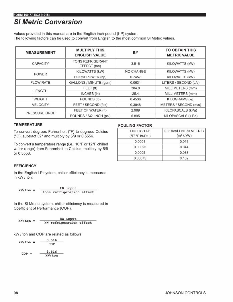
JOHNSON CONTROLS
FORM 160.77-EG2 (1015)
98
SI Metric ConversionValues provided in this manual are in the English inch-pound (I-P) system. The following factors can be used to convert from English to the most common Sl Metric values.
TEMPERATURE
To convert degrees Fahrenheit (°F) to degrees Celsius (°C), subtract 32° and multiply by 5/9 or 0.5556.
To convert a temperature range (i.e., 10°F or 12°F chilled water range) from Fahrenheit to Celsius, multiply by 5/9 or 0.5556.
EFFICIENCY
In the English l-P system, chiller efficiency is measured in kW / ton:
kW/ton = kW inputtons refrigeration effect
In the Sl Metric system, chiller efficiency is measured in Coefficient of Performance (COP).
kW/ton = kW inputkW refrigeration effect
kW / ton and COP are related as follows:
kW/ton = 3.516COP
COP = 3.516kW/ton
MEASUREMENT MULTIPLY THISENGLISH VALUE BY TO OBTAIN THIS
METRIC VALUE
CAPACITYTONS REFRIGERANT
EFFECT (ton)3.516 KILOWATTS (kW)
POWERKILOWATTS (kW) NO CHANGE KILOWATTS (kW)
HORSEPOWER (hp) 0.7457 KILOWATTS (kW)FLOW RATE GALLONS / MINUTE (gpm) 0.0631 LITERS / SECOND (L/s)
LENGTHFEET (ft) 304.8 MILLIMETERS (mm)
INCHES (in) 25.4 MILLIMETERS (mm)WEIGHT POUNDS (lb) 0.4536 KILOGRAMS (kg)
VELOCITY FEET / SECOND (fps) 0.3048 METERS / SECOND (m/s)
PRESSURE DROPFEET OF WATER (ft) 2.989 KILOPASCALS (kPa)
POUNDS / SQ. INCH (psi) 6.895 KILOPASCALS (k Pa)
FOULING FACTORENGLISH l-P(fT2 °F hr/Btu)
EQUIVALENT Sl METRIC (m2 k/kW)
0.0001 0.0180.00025 0.0440.0005 0.088
0.00075 0.132

FORM 160.77-EG2 (1015)
JOHNSON CONTROLS 99
Notes

Printed on recycled paperForm 160.77-EG2 (1015) New Release© 2015 Johnson Controls, Inc. P.O. Box 423, Milwaukee, WI 53201 Printed in USAwww.johnsoncontrols.comIssued on 10/12/2015