
MODEL YD DUAL CENTRIFUGAL COMPRESSOR CHILLERS STYLE D · one compressor runs, as the chiller...
122
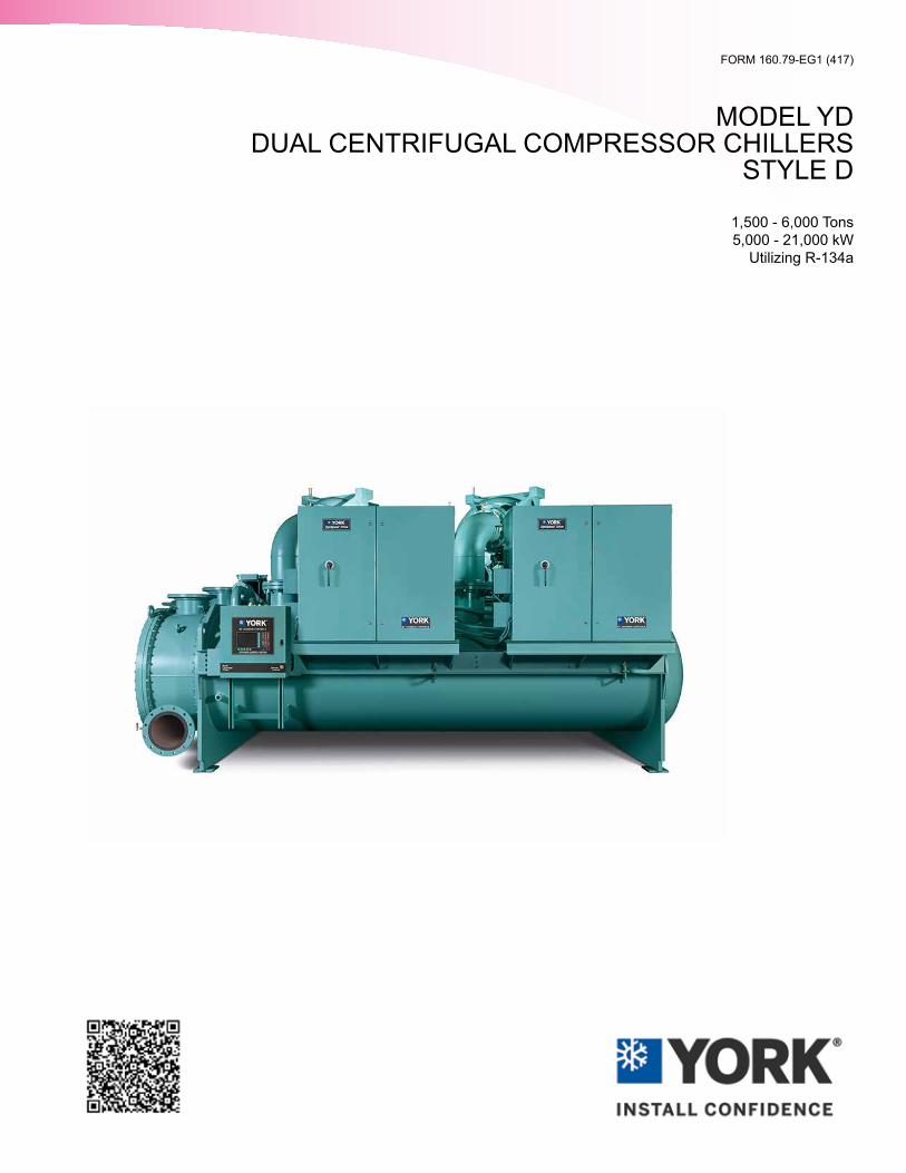
FORM 160.79-EG1 (417) MODEL YD DUAL CENTRIFUGAL COMPRESSOR CHILLERS STYLE D 1,500 - 6,000 Tons 5,000 - 21,000 kW Utilizing R-134a
Transcript of MODEL YD DUAL CENTRIFUGAL COMPRESSOR CHILLERS STYLE D · one compressor runs, as the chiller...
FORM 160.79-EG1 (417)
MODEL YD DUAL CENTRIFUGAL COMPRESSOR CHILLERS
STYLE D
1,500 - 6,000 Tons 5,000 - 21,000 kW
Utilizing R-134a
JOHNSON CONTROLS
FORM 160.79-EG1 (417)
2
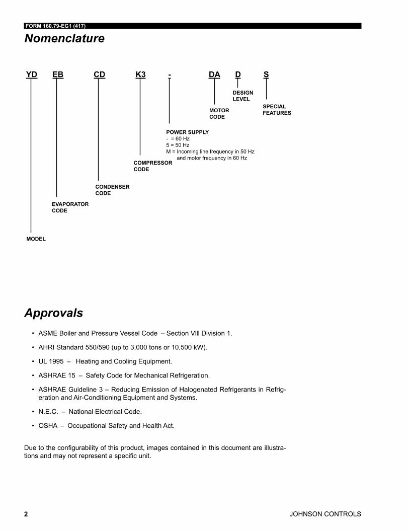
Nomenclature
Approvals• ASME Boiler and Pressure Vessel Code – Section Vlll Division 1.
• AHRI Standard 550/590 (up to 3,000 tons or 10,500 kW).
• UL 1995 – Heating and Cooling Equipment.
• ASHRAE 15 – Safety Code for Mechanical Refrigeration.
• ASHRAE Guideline 3 – Reducing Emission of Halogenated Refrigerants in Refrig-eration and Air-Conditioning Equipment and Systems.
• N.E.C. – National Electrical Code.
• OSHA – Occupational Safety and Health Act.
Due to the configurability of this product, images contained in this document are illustra-tions and may not represent a specific unit.
YD EB CD K3 - DA D S
MODEL
EVAPORATOR CODE
POWER SUPPLY- = 60 Hz5 = 50 HzM = Incoming line frequency in 50 Hz
and motor frequency in 60 Hz
MOTORCODE
SPECIAL FEATURES
CONDENSERCODE
COMPRESSORCODE
DESIGNLEVEL
FORM 160.79-EG1 (417)
JOHNSON CONTROLS 3
Table of ContentsNOMENCLATURE ................................................................................................................................................... 2
INTRODUCTION ...................................................................................................................................................... 5
SUSTAINABILITY FOCUS ...................................................................................................................................... 9
UNIT COMPONENTS ............................................................................................................................................ 13
EQUIPMENT OVERVIEW ...................................................................................................................................... 15
SYSTEM FLOW DIAGRAM .................................................................................................................................. 20
OPTIVIEW CONTROL CENTER ........................................................................................................................... 22
STARTERS AND DRIVES ..................................................................................................................................... 34
ACCESSORIES AND MODIFICATIONS ............................................................................................................... 45
APPLICATION DATA ............................................................................................................................................. 48
ELECTRICAL CONSIDERATIONS ....................................................................................................................... 61
DIMENSIONS ......................................................................................................................................................... 74
ISOLATORS ........................................................................................................................................................... 95
COMPONENT DIMENSIONS ................................................................................................................................ 99
WEIGHTS ............................................................................................................................................................. 102
GUIDE SPECIFICATIONS ................................................................................................................................... 103
SI METRIC CONVERSION .................................................................................................................................. 120

JOHNSON CONTROLS
FORM 160.79-EG1 (417)
4
THIS PAGE INTENTIONALLY LEFT BLANK.
FORM 160.79-EG1 (417)
JOHNSON CONTROLS 5
Introduction
The YORK® YD™ chillers offer a complete combination of features for total owner satisfac-tion. The YD line of chillers utilize two YORK centrifugal compressors operating in parallel on a common set of heat exchanger shells to obtain large chiller capacities, and efficient part load operation.
MATCHED COMPONENTS MAXIMIZE EFFICIENCY
Actual chiller efficiency cannot be determined by ana lyzing the theoretical efficiency of any one chiller com ponent. It requires a specific combination of heat exchanger, compressor, and motor performance to achieve the lowest system kW/ton. YORK YD chiller technology matches chiller system components to provide maximum chiller efficiency under actual – not just theoretical – operating conditions.
REAL WORLD ENERGY PERFORMANCE
Johnson Controls pioneered the term “Real World Energy” to illustrate the energy saving potential of focusing on chiller performance during off design conditions. Off design is not only part load, but full load operation as well, with reduced entering condenser water tem-peratures (ECWTs). Where chillers operate 99% of the time, operating costs add up.
YORK YD chillers are designed to operate on a continuous basis with cold ECWTs and full condenser flow at all load points, taking full advantage of Real-World conditions. This type of operation benefits the cooling tower as well; reducing cycling of the fan motor and ensuring good coverage of the cooling tower fill.
The YD dual compressor chiller provides further energy savings by running in single com-pressor mode to achieve the best operational performance. At part loads below 40%, only one compressor runs, as the chiller operates more efficiently by running a single more fully loaded compressor. Between 40% and 60% part load, the second compressor could be on or off depending on best performance. Part loads above 60% require both compressors to share the load. The two compressors share a common refrigerant circuit, thereby utilizing the full heat transfer surface available for part load single compressor operation.
YORK YD chillers offer the most efficient Real World operation of any chiller, meaning lower operating costs and an excellent return on your chiller investment.
OPEN DRIVE DESIGN
Hermetic-motor burnout can cause catastrophic dam age to a chiller. The entire chiller must be cleaned and the refrigerant replaced. YORK YD centrifugal chillers eliminate this risk by utilizing air-cooled motors. Refrigerant never comes in contact with the motor, preventing contamination of the rest of the chiller.
Insurance companies that offer policies on large air conditioning equipment often consider air-cooled mo tors a significant advantage over hermetic refrigerant cooled units.
The YD chiller uses two motors, each roughly half the size of a motor used on an equivalent size single compressor chiller. By staggering the start of these motors, the starting in-rush current of each smaller motor is less (Electromechanical and Solid State Starter only). This provides a lower burden on the building electrical system. Also, using two smaller motors allows low voltage compressor drive motors to be applied on larger chillers. This can be an advantage for applications where medium voltage power sources are not available.
Off-design is not only part load, but full load operation as well, with reduced entering condenser water temperatures (ECWTs)
JOHNSON CONTROLS
FORM 160.79-EG1 (417)
6
Introduction (Cont'd)
The YD chillers feature two variable speed drive oil pumps, moni-toring and providing the right amount of oil flow to each compres-sor on a continuous basis.
HIGH-EFFICIENCY HEAT EXCHANGERS
YD chiller heat exchangers offer the latest tech nology in heat transfer surface design to give you maxi mum efficiency and compact design. Waterside and refrigerant-side design enhancements minimize both energy consumption and tube fouling.
SINGLE-STAGE COMPRESSOR DESIGN AND EFFICIENCY PROVEN IN THE MOST DEMANDING APPLICATIONS
Designed to be the most reliable chillers we’ve ever made, YORK YD centrifugal chillers incorporate single stage compressor design. With fewer moving parts and straightforward, efficient engineering, YORK single stage compressors have proven durability records in the U.S. Navy, hospitals, chemical plants, gas processing plants, and in other applications where minimal downtime is a crucial concern.
In thousands of installations worldwide, YORK single stage compressors are working to reduce energy costs. High strength aluminum alloy compressor impel lers feature back-ward-curved vanes for high efficiency. Airfoil shaped pre-rotation vanes minimize flow disrup tion for the most efficient part load performance. Pre cisely positioned and tightly fit-ted, they allow the compressor to unload smoothly from 100% to minimum load for excellent operation in air conditioning applications.
PRECISION CONTROL OF COMPRESSOR OIL PRESSURE
Utilizing our expertise in variable speed drive technology and applications, Johnson Con-trols has moved beyond the fixed head and bypass approach of oil pressure control. The old approach only assures oil pressure at the outlet of the pump rather than at the compres-sor, and allows no adjustment during chiller operation. The YD chillers feature two variable speed drive oil pumps, monitoring and providing the right amount of oil flow to each com-pressor on a continuous basis. This design also provides sophisticated electronic monitor-ing and protection of the oil pump electrical supply, ensuring long life and reliable operation of the oil pump motor. Variable speed drive technology reduces oil pump power consump-tion, running only at the speed required, rather than at full head with a pressure regulating bypass valve.
FACTORY PACKAGING REDUCES FIELD LABOR COSTS
YORK YD centrifugal chillers are designed to keep installation costs low. Installation access could or could not be a problem, so the H9, K1, and K2 compressor size YD dual compres-sor chillers may be shipped using Form 2, Form 3, or Form 7 methods. Form 2 shipment allows the chiller to be shipped completely packaged as one assembly. Form 3 shipment requires the two drive lines to ship separate from the shells as three major assemblies. When installation requirements are non-trivial, Form 7 shipment ensures the evaporator and condenser shells are split apart, separate from the two drive lines into four major as-semblies. In order to save on shipping and rigging costs, larger K3, K4, and K7 compressor size units mandate the use of Form 7 shipment. In all three shipping methods, refrigerant and oil charges are shipped separately, connections are closed/flanged, wiring connections are simple plug-type to ensure a simple chiller commissioning utilizing a starter, and heat exchanger refrigerant sides are charged with nitrogen.
FORM 160.79-EG1 (417)
JOHNSON CONTROLS 7
Introduction (Cont'd)TAKE ADVANTAGE OF COLDER COOLING TOWER WATER TEMPERATURES
YORK YD centrifugal chillers have been de signed to take full advantage of colder cool-ing tower water temperatures, which are naturally available dur ing most operating hours. Considerable energy savings are available by letting tower water temperature drop, rather than artificially holding it above 75°F (23.9°C), especially at full load and full condenser flow, as some chillers require. 50°F (10°C) is used as the rule of thumb in many scenarios depending on the conditions, but this Min. ECWT should be validated using the formula on page 53.
OFF DESIGN PERFORMANCE
Since the vast majority of its operating hours are spent at off-design conditions, a chiller should be chosen not only to meet the full load design, but also for its ability to perform efficiently at lower loads and lower tower water temperatures. It is not uncommon for chill-ers with the same full load kW/ton to have an operating cost difference of over 10% due to part-load operation.
Part load information can be easily and accurately generated by use of the computer. And because it is so important to an owner’s operating budget, this informa tion has now been standardized within the AHRI Certifi cation Program in the form of an Integrated Part Load Value (IPLV), and Non Standard Part Load Value (NPLV).
The IPLV/NPLV formulas from AHRI Standard 550/590 much more closely track actual chill-er operations. A more detailed analysis must take into account actual build ing load profiles, and local weather data. Part load performance data should be obtained for each job using its own design criteria.
AHRI CERTIFICATION PROGRAM
YORK YD chillers have been tested and certified by Air Conditioning, Heating and Refrig-eration Institute (AHRI) in accordance with the latest edition of AHRI Standard 550/590 (I-P) & 551/591 (up to 3,000 tons or 10.550 kW). Under this Certification Program, chillers are regularly tested in strict compliance with this Standard. This provides an independent, third-party verification of chiller performance. Refer to the AHRI site at: www.ah rinet.org/water_chilling+packages+using+vapor+compression+cycle+_water_cooled_.aspx for complete Pro-gram Scope, Inclusions, and Exclusions as some options listed herein fall outside the scope of the AHRI certification program. For verification of certification, go to the AHRI Directory at www.ahridirectory.org.
UL COMPLIANCE – YOUR ASSURANCE OF RELIABILITY
YORK YD centrifugal chillers are approved to UL Standard 1995 for listing by a qualified nationally recognized testing laboratory for the United States and Canada. Recognition of safety and reliability is your assurance of trouble free performance in day today building operation. Some chiller options or modifications may affect the UL compliance of the chiller. Some examples include: special motor enclosures (like TEFC, TEWAC, or TEAAC) or spe-cial panels (NEMA 4X) or special unit wiring options (anything other than NEMA 1). For further clarification, contact your local Johnson Controls Sales Office.
JOHNSON CONTROLS
FORM 160.79-EG1 (417)
8
Introduction (Cont'd)COMPUTERIZED PERFORMANCE RATINGS
Each chiller is custom-matched to meet the individual building load and energy require-ments. Several standard heat exchanger tube bundle sizes and pass arrangements are available to provide the best possible match.
It is not practical to provide tabulated performance for each combination, as the energy requirements at both full and part load vary significantly with each heat exchanger and pass arrangement. Computerized ratings are available through each Johnson Controls Sales Of-fice. These ratings can be tailored to specific job requirements.

FORM 160.79-EG1 (417)
JOHNSON CONTROLS 9
Sustainability Focus
OZONE-DEPLETION POTENTIAL (ODP)
The YORK YD chiller employs one of the most environmentally friendly refrigerants avail-able today, HFC-134a, with no Ozone-Depletion Potential (ODP) and no phase out date per the Montreal Protocol.
Ozone is a very small part of the atmosphere, but its presence is nevertheless vital to hu-man well-being. Most ozone resides in the upper part of the atmosphere. This region, called the stratosphere, is more than 6 miles (10 km) above the Earth’s surface. There, about 90% of atmospheric ozone is contained in the “ozone layer,” which shields us from harmful ultraviolet radiation from the sun. However, it was discovered in the mid-1970s that some human-produced chemicals could destroy ozone and deplete the ozone layer. The resulting increase in ultraviolet radiation at the Earth’s surface may increase the incidences of skin cancer and eye cataracts. Following the discovery of this environmental issue, researchers focused on gaining a better understanding of this threat to the ozone layer.
Monitoring stations showed that ozone-depleting chemicals were steadily increasing in the atmosphere. These trends were linked to growing production and use of chemicals like chlo-rofluorocarbons (CFCs) for refrigeration and air conditioning, foam blowing, and industrial cleaning. Measurements in the laboratory and the atmosphere characterized the chemical reactions that were involved in ozone destruction. Computer models employing this infor-mation could predict how much ozone depletion was occurring and how much more could occur in the future.
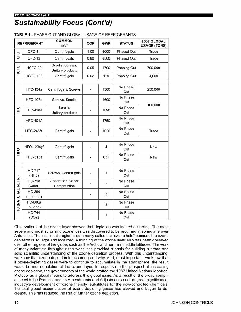
The typical usage of the refrigerant, the phase-out status by the Montreal Protocol and the global usage of refrigerant in tons is shown in the Table 1 on page 10.
JOHNSON CONTROLS
FORM 160.79-EG1 (417)
10
Sustainability Focus (Cont'd)TABLE 1 - PHASE OUT AND GLOBAL USAGE OF REFRIGERANTS
REFRIGERANTCOMMON
USEODP GWP STATUS 2007 GLOBAL
USAGE (TONS)
CFC
CFC-11 Centrifugals 1.00 5000 Phased Out Trace
CFC-12 Centrifugals 0.80 8500 Phased Out Trace
HC
FC HCFC-22Scrolls, Screws, Unitary products
0.05 1700 Phasing Out 700,000
HCFC-123 Centrifugals 0.02 120 Phasing Out 4,000
HFC
HFC-134a Centrifugals, Screws - 1300No Phase
Out250,000
HFC-407c Screws, Scrolls - 1600No Phase
Out100,000
HFC-410AScrolls,
Unitary products- 1890
No Phase Out
HFC-404A - 3750No Phase
Out
HFC-245fa Centrifugals - 1020No Phase
OutTrace
HFO
HFO-1234yf Centrifugals - 4No Phase
OutNew
HFO-513a Centrifugals - 631No Phase
OutNew
HC
(NAT
UR
AL
REF
R.)
HC-717 (NH3)
Screws, Centrifugals - 1No Phase
OutHC-718 (water)
Absorption, Vapor Compression
- -No Phase
OutHC-290
(propane)- 3
No Phase Out
HC-600a (butane)
- 3No Phase
OutHC-744 (CO2)
- 1No Phase
Out
Observations of the ozone layer showed that depletion was indeed occurring. The most severe and most surprising ozone loss was discovered to be recurring in springtime over Antarctica. The loss in this region is commonly called the “ozone hole” because the ozone depletion is so large and localized. A thinning of the ozone layer also has been observed over other regions of the globe, such as the Arctic and northern middle latitudes. The work of many scientists throughout the world has provided a basis for building a broad and solid scientific understanding of the ozone depletion process. With this understanding, we know that ozone depletion is occurring and why. And, most important, we know that if ozone-depleting gases were to continue to accumulate in the atmosphere, the result would be more depletion of the ozone layer. In response to the prospect of increasing ozone depletion, the governments of the world crafted the 1987 United Nations Montreal Protocol as a global means to address this global issue. As a result of the broad compli-ance with the Protocol and its Amendments and Adjustments and, of great significance, industry’s development of “ozone friendly” substitutes for the now-controlled chemicals, the total global accumulation of ozone-depleting gases has slowed and begun to de-crease. This has reduced the risk of further ozone depletion.
FORM 160.79-EG1 (417)
JOHNSON CONTROLS 11
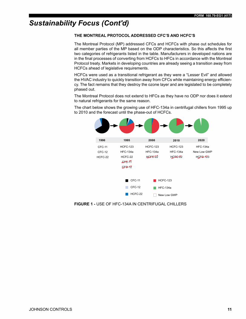
Sustainability Focus (Cont'd)THE MONTREAL PROTOCOL ADDRESSED CFC’S AND HCFC’S
The Montreal Protocol (MP) addressed CFCs and HCFCs with phase out schedules for all member parties of the MP based on the ODP characteristics. So this affects the first two categories of refrigerants listed in the table. Manufacturers in developed nations are in the final processes of converting from HCFCs to HFCs in accordance with the Montreal Protocol treaty. Markets in developing countries are already seeing a transition away from HCFCs ahead of legislative requirements. HCFCs were used as a transitional refrigerant as they were a “Lesser Evil” and allowed the HVAC industry to quickly transition away from CFCs while maintaining energy efficien-cy. The fact remains that they destroy the ozone layer and are legislated to be completely phased out. The Montreal Protocol does not extend to HFCs as they have no ODP nor does it extend to natural refrigerants for the same reason.The chart below shows the growing use of HFC-134a in centrifugal chillers from 1995 up to 2010 and the forecast until the phase-out of HCFCs.
1990 1995 2000 2010 2020
CFC-11
CFC-12
HCFC-22
HCFC-123
HFC-134a
HCFC-22
CFC-11
CFC-12
HCFC-123
HFC-134a
HCFC-22
HCFC-123
HFC-134a
HCFC-22
HFC-134a
New Low GWP
HCFC-123
CFC-11
CFC-12
HCFC-22
HCFC-123
HFC-134a
New Low GWP
FIGURE 1 - USE OF HFC-134A IN CENTRIFUGAL CHILLERS
JOHNSON CONTROLS
FORM 160.79-EG1 (417)
12
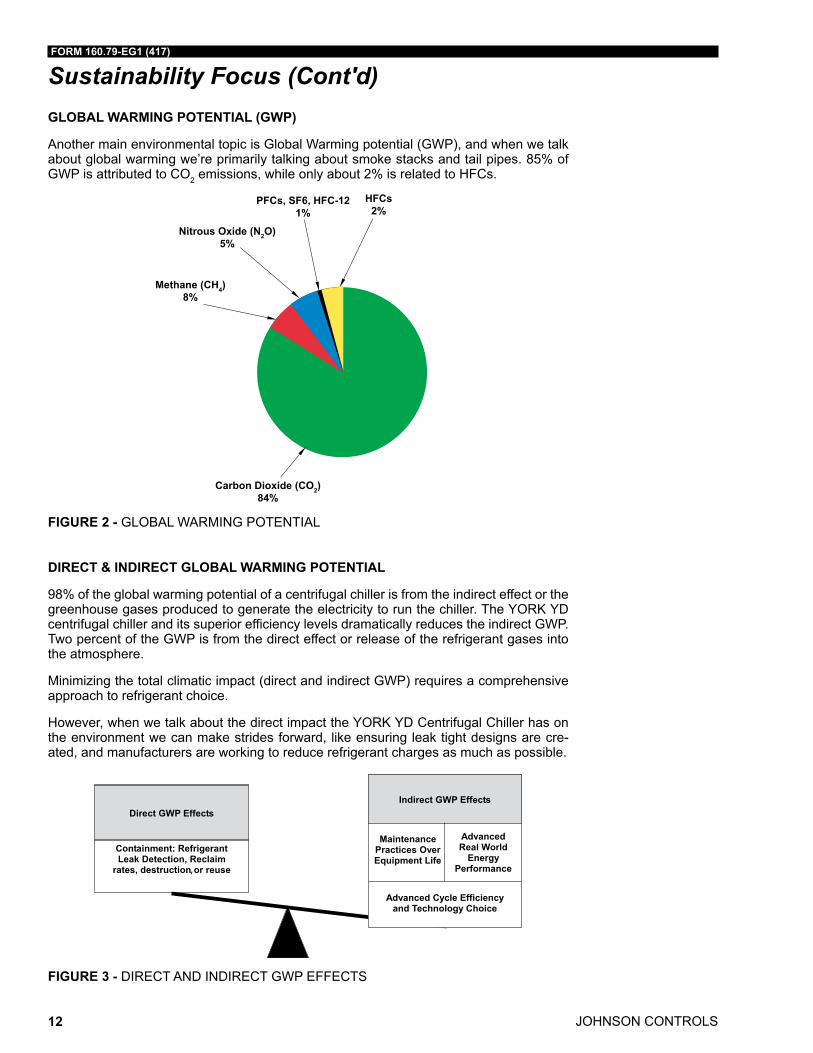
Sustainability Focus (Cont'd)GLOBAL WARMING POTENTIAL (GWP)
Another main environmental topic is Global Warming potential (GWP), and when we talk about global warming we’re primarily talking about smoke stacks and tail pipes. 85% of GWP is attributed to CO2 emissions, while only about 2% is related to HFCs.
Methane (CH4)8%
Nitrous Oxide (N2O)5%
PFCs, SF6, HFC-121%
HFCs2%
Carbon Dioxide (CO2)84%
FIGURE 2 - GLOBAL WARMING POTENTIAL
DIRECT & INDIRECT GLOBAL WARMING POTENTIAL
98% of the global warming potential of a centrifugal chiller is from the indirect effect or the greenhouse gases produced to generate the electricity to run the chiller. The YORK YD centrifugal chiller and its superior efficiency levels dramatically reduces the indirect GWP. Two percent of the GWP is from the direct effect or release of the refrigerant gases into the atmosphere.
Minimizing the total climatic impact (direct and indirect GWP) requires a comprehensive approach to refrigerant choice.
However, when we talk about the direct impact the YORK YD Centrifugal Chiller has on the environment we can make strides forward, like ensuring leak tight designs are cre-ated, and manufacturers are working to reduce refrigerant charges as much as possible.
,
FIGURE 3 - DIRECT AND INDIRECT GWP EFFECTS
FORM 160.79-EG1 (417)
JOHNSON CONTROLS 13
Unit Components
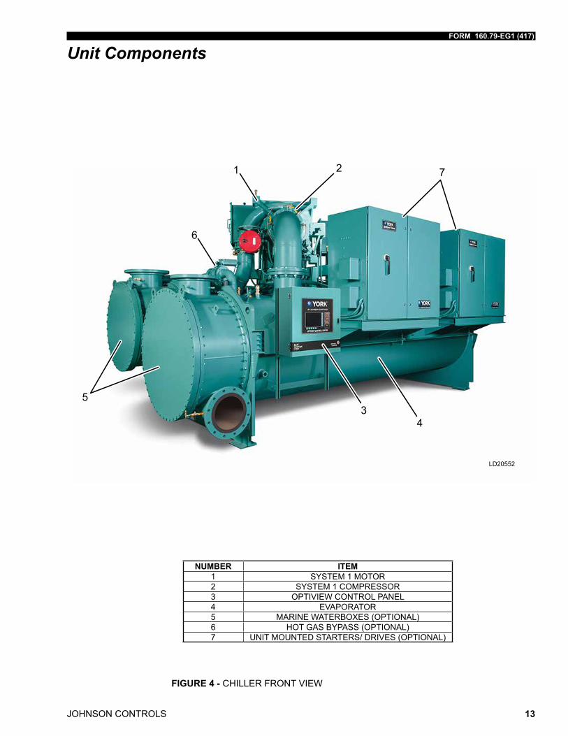
NUMBER ITEM1 SYSTEM 1 MOTOR2 SYSTEM 1 COMPRESSOR3 OPTIVIEW CONTROL PANEL4 EVAPORATOR5 MARINE WATERBOXES (OPTIONAL)6 HOT GAS BYPASS (OPTIONAL)7 UNIT MOUNTED STARTERS/ DRIVES (OPTIONAL)
FIGURE 4 - CHILLER FRONT VIEW
2
LD20552
1
34
5
6
7
JOHNSON CONTROLS
FORM 160.79-EG1 (417)
14
Unit Components (Cont'd)
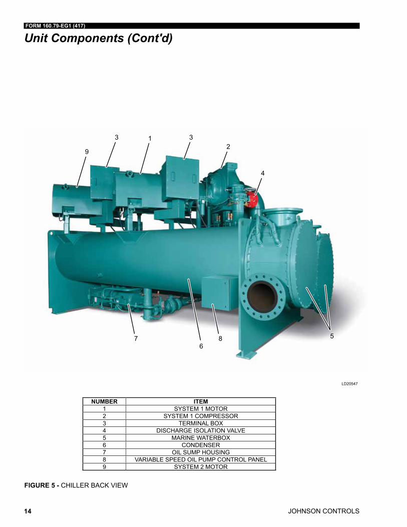
NUMBER ITEM1 SYSTEM 1 MOTOR2 SYSTEM 1 COMPRESSOR3 TERMINAL BOX4 DISCHARGE ISOLATION VALVE5 MARINE WATERBOX6 CONDENSER7 OIL SUMP HOUSING8 VARIABLE SPEED OIL PUMP CONTROL PANEL9 SYSTEM 2 MOTOR
FIGURE 5 - CHILLER BACK VIEW
LD20547
3 32
4
1
9
56
7 8
FORM 160.79-EG1 (417)
JOHNSON CONTROLS 15
Equipment Overview
Lubrication oil is force-fed to all bear-ings, gears and rotat-ing surfaces by a variable speed drive pump which operates prior to startup...
GENERAL
The YORK YD Centrifugal Liquid Chillers are completely factory packaged including the evaporator, condenser, compressor, motor, lubrication system, and all interconnecting unit piping and wiring. Larger (K3, K4, and K7 compressors) YD chillers are disassembled for shipment.
The initial charge of refrigerant and oil is supplied for each chiller, and is shipped separately from the unit. Actual shipping procedures will depend on a number of project specific details.
The services of a Johnson Controls factory-trained or field service representative are in-curred to supervise or perform the final leak testing, charging, the initial start up, and concur-rent operator instructions.
COMPRESSOR
Each compressor is a single-stage centrifugal type pow ered by an open-drive electric mo-tor. The casing is fully accessible with vertical circular joints and fabricated of close-grain cast iron. The complete operating assembly is removable from the compressor and scroll housing.
The rotor assembly consists of a heat-treated alloy steel drive shaft and impeller shaft with a high strength, cast aluminum alloy, fully shrouded impeller. The impeller is designed for bal-anced thrust and is dynami cally balanced and overspeed tested for smooth, vibra tion free operation.
The insert type journal and thrust bearings are fabri cated of aluminum alloy and are preci-sion bored and axially grooved. The specially engineered, single helical gears with crowned teeth are designed so that more than one tooth is in contact at all times to provide even distribution of compressor load and quiet operation. Gears are integrally assembled in the compressor rotor support and are film lubricated. Each gear is individually mounted in its own journal and thrust bearings to isolate it from impeller and motor forces.
COMPRESSOR DISCHARGE VALVES
Automated valves are provided in the discharge of each compressor. The discharge valve ensures that there is no backspin of the non running compressor when the chiller is in single compressor operating mode. These valves are cycled by the control panel during the start and stop sequence of the lag (2nd) compressor.
OPTISOUND™ CONTROL
The YORK OptiSound Control is a patented combination of centrifugal chiller hardware and software that reduces operational sound levels, expands the chiller operating range, and improves chiller performance. The OptiSound Control feature continuously monitors the characteristics of the compressor discharge gas and optimizes the diffuser spacing to mini-mize gas flow disruptions from the impeller. This innovative technology improves operating sound levels of the chiller an average of 7 dBA, and up to 13 dBA on the largest models. It can also reduce part load sound levels below the full load level.
JOHNSON CONTROLS
FORM 160.79-EG1 (417)
16
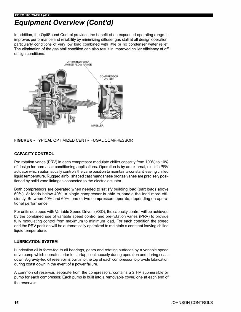
Equipment Overview (Cont'd)In addition, the OptiSound Control provides the benefit of an expanded operating range. It improves performance and reliability by minimizing diffuser gas stall at off design operation, particularly conditions of very low load combined with little or no condenser water relief. The elimination of the gas stall condition can also result in improved chiller efficiency at off design conditions.
FIGURE 6 - TYPICAL OPTIMIZED CENTRIFUGAL COMPRESSOR
CAPACITY CONTROL
Pre rotation vanes (PRV) in each compressor modulate chiller capacity from 100% to 10% of design for normal air conditioning applications. Operation is by an external, electric PRV actuator which automatically controls the vane position to maintain a constant leaving chilled liquid tempera ture. Rugged airfoil shaped cast manganese bronze vanes are precisely posi-tioned by solid vane linkages connected to the electric actuator.
Both compressors are operated when needed to satisfy building load (part loads above 60%). At loads below 40%, a single compressor is able to handle the load more effi-ciently. Between 40% and 60%, one or two compressors operate, depending on opera-tional performance.
For units equipped with Variable Speed Drives (VSD), the capacity control will be achieved by the combined use of variable speed control and pre-rotation vanes (PRV) to provide fully modulating control from maximum to minimum load. For each condition the speed and the PRV position will be automatically optimized to maintain a constant leaving chilled liquid temperature.
LUBRICATION SYSTEM
Lubrication oil is force-fed to all bearings, gears and rotating surfaces by a variable speed drive pump which operates prior to startup, continuously during operation and during coast down. A gravity-fed oil reservoir is built into the top of each compressor to provide lubrication during coast down in the event of a power failure.
A common oil reservoir, separate from the compressors, contains a 2 HP submersible oil pump for each compressor. Each pump is built into a removable cover, one at each end of the reservoir.
FORM 160.79-EG1 (417)
JOHNSON CONTROLS 17
Equipment Overview (Cont'd)Two 2 kW immersion oil heaters are provided, one mounted in each pump cover. The heat-ers are thermostatically controlled from the sump oil temperature sensor.
A refrigerant cooled oil cooler is provided after each oil pump, eliminating the need for field water piping. A thermostatically controlled expansion valve maintains the required oil tem-perature supply from each oil cooler to its compressor. Oil is filtered by externally mounted ½ micron replaceable spin-on element oil filters, equipped with service valves. An automatic oil return system recovers any oil that may have migrated to the evaporator. Oil piping is completely factory installed.
MOTOR DRIVELINE
The compressor motors are open drip-proof, squirrel cage, induction type constructed to YORK design speci fications. 60 hertz motors operate at 3570 rpm. 50 hertz motors operate at 2975 rpm.
The open motor is provided with a D-flange, and is factory mounted to a cast iron adaptor mounted on the compressor. This unique design allows the motor to be rigidly coupled to the compressor to provide factory alignment of motor and compressor shafts.
Motor drive shaft is directly connected to the compres sor shaft with a flexible disc coupling. Coupling has all metal construction with no wearing parts to assure long life, and no lubrica-tion requirements to provide low maintenance.
A large, steel terminal box with gas keted front access cover is provided on each motor for field connected conduit. There are six terminals (three for medium voltage) brought through the motor casing into the terminal box. Jumpers are furnished for three lead types of starting. Motor terminal lugs are not furnished. Overload/over current transformers are furnished with all units.
HEAT EXCHANGERS
Shells - Evaporator and condenser shells are fabricated from rolled carbon steel plates with fusion welded seams. Carbon steel tube sheets, drilled and reamed to accommodate the tubes, are welded to the end of each shell. Intermediate tube supports are fabricated from carbon steel plates, drilled and reamed to eliminate sharp edges, and spaced no more than 4' (1.2 m) apart. The refrigerant side of each shell is designed, tested, and stamped in accordance with ASME Boiler and Pressure Vessel Code, Section VIII – Divi-sion I, or other pressure vessel code as appropriate.
Tubes - Heat exchanger tubes are state of the art, high efficiency, externally and internally enhanced type to provide optimum performance. Tubes in both the evaporator and con-denser are 3/4" (19 mm) or 1” (25 mm) O.D. copper alloy and utilize the “skip fin” design, providing a smooth internal and external surface at each intermediate tube support. This provides extra wall thickness (up to twice as thick) and non work hardened copper at the support location, extending the life of the heat exchangers. Each tube is roller expanded into the tube sheets providing a leak proof seal, and is individually replaceable.
JOHNSON CONTROLS
FORM 160.79-EG1 (417)
18
Equipment Overview (Cont'd)Evaporator - The evaporator is a shell and tube, flooded type heat exchanger. A distributor trough provides uniform distribution of refrigerant over the entire shell length to yield opti-mum heat transfer. Mesh eliminators are located above the tube bundle to prevent liquid refrigerant carryover into the compressor. A 2.25" (57 mm) liquid level sight glass is conve-niently located on the side of the shell to aid in determining proper refrigerant charge. The evaporator shell contains a single relief valve arrangement set at 180 psig (1.34 MPa). A 1" (25 mm) refrigerant charging valve is provided.
Condenser - The condenser is a shell and tube type, with discharge gas diffuser to prevent direct high velocity impingement on the tubes. The diffusers provide dynamic pressure re-covery and enhanced chiller efficiency. An integral sub-cooler is located at the bottom of the condenser shell providing highly effective liquid refrigerant subcooling to provide the highest cycle efficiency. The condenser contains dual refrigerant relief valves set at 235 psig (1.72 MPa).
Waterboxes - Standard waterboxes are compact type and fabricated of steel. The design working pressure is 150 psig (1.14 MPa) and the boxes are tested at 225 psig (1.65 MPa). Integral steel water baffles are located and welded within the waterbox to provide the re-quired pass arrangements. Stub-out water nozzle connections with ANSI/AWWA C-606 couplings grooves are welded to the waterboxes. These nozzle connections are suit-able for ANSI/AWWA C-606 couplings, welding or flanges, and are capped for shipment. Plugged drain and vent connections are provided in each waterbox. Although compact waterboxes are installed on standard units, marine waterboxes are available. See the Ac-cessories and Modifications section for details.
ISOLATION MOUNTING
The unit is provided with vibration isolation mounts of nominal 1" (25 mm) operating height. The pads have a neoprene pad to contact the foundation, bonded to a steel plate. The vibration isolation pads assemblies mount under steel plates affixed to the chiller tube sheets.
REFRIGERANT FLOW CONTROL
Refrigerant flow to the evaporator is controlled by the YORK variable orifice control sys-tem. Liquid refrigerant level is continuously monitored to provide optimum subcooler, con-denser and evaporator performance. The variable orifice electronically adjusts to all real world operating conditions, providing the most efficient and reliable operation of refriger-ant flow control.
REFRIGERANT CONVERSION TO A LOW GWP - HFO
Customers can purchase YD style D chillers using HFC-134a now, and in the future can be replaced by a low GWP, non-flammable, and A1 Toxicity classification one (HFO-513A) if/when necessary during the chiller’s life. No hardware modification is necessary, just a new OptiView software version updated for refrigerant propriety is required.
REFRIGERANT CONTAINMENT
The standard unit has been designed as a complete and compact factory packaged chill-er. As such, it has mini mum joints from which refrigerant can leak. The entire assembly has been thoroughly leak tested at the factory prior to shipment. The YORK chiller in-cludes service valves conveniently located to facilitate transfer of refrig erant to a remote refrigerant storage/recycling system.
FORM 160.79-EG1 (417)
JOHNSON CONTROLS 19
Equipment Overview (Cont'd)PAINT
Exterior surfaces are protected with one coat of Carib bean blue, durable alkyd-modified, vinyl enamel, ma chinery paint.
SHIPMENT
YORK YD centrifugal chillers are designed to keep installation costs low. Installation ac-cess could or could not be a problem, so the H9, K1, and K2 compressor size YD dual compressor chillers may be shipped using Form 2, Form 3, or Form 7 methods. Form 2 shipment allows the chiller to be shipped completely packaged as one assembly. Form 3 shipment requires the two drive lines to ship separate from the shells as three major assemblies. When installation requirements are non-trivial, Form 7 shipment ensures the evaporator and condenser shells are split apart, separate from the two drive lines into four major assemblies. In order to save on shipping and rigging costs, larger K3, K4, and K7 compressor size units mandate the use of Form 7 shipment. In all three shipping methods, refrigerant and oil charges are shipped separately, connections are closed/flanged, wir-ing connections are simple plug-type to ensure a simple chiller commissioning utilizing a starter, and heat exchanger refrigerant sides are charged with nitrogen.
WATER FLOW SWITCHES
Thermal-type water flow switches are factory mounted in the chilled and condenser water nozzles, and are factory wired to the OptiView control panel. These solid state flow sen-sors have a small internal heating element. They use the cooling effect of the flowing fluid to sense when an adequate flow rate has been established. The sealed sensor probe is 316 stainless steel, which is suited to very high working pressures.
JOHNSON CONTROLS
FORM 160.79-EG1 (417)
20
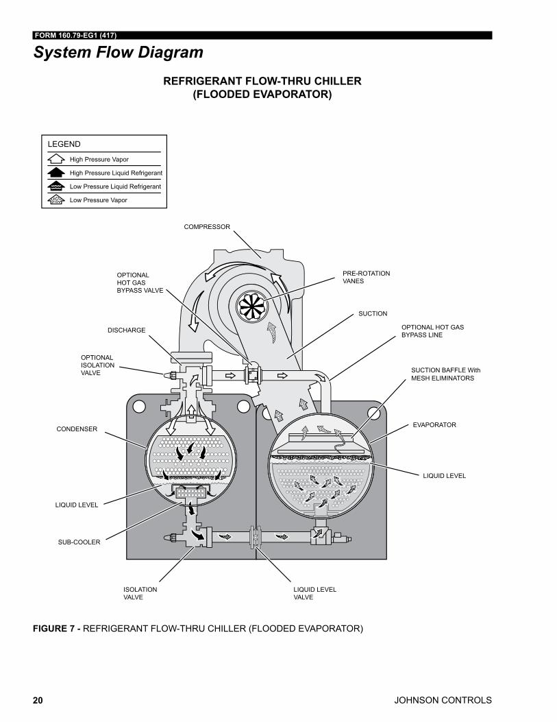
System Flow Diagram
High Pressure Vapor
High Pressure Liquid Refrigerant
Low Pressure Liquid Refrigerant
Low Pressure Vapor
LEGEND
COMPRESSOR
EVAPORATOR
DISCHARGE
PRE-ROTATIONVANES
SUCTION BAFFLE With MESH ELIMINATORS
SUB-COOLER
LIQUID LEVEL
CONDENSER
SUCTION
LIQUID LEVELVALVE
LIQUID LEVEL
OPTIONALISOLATIONVALVE
ISOLATIONVALVE
OPTIONALHOT GASBYPASS VALVE
OPTIONAL HOT GASBYPASS LINE
REFRIGERANT FLOW-THRU CHILLER (FLOODED EVAPORATOR)
FIGURE 7 - REFRIGERANT FLOW-THRU CHILLER (FLOODED EVAPORATOR)
FORM 160.79-EG1 (417)
JOHNSON CONTROLS 21
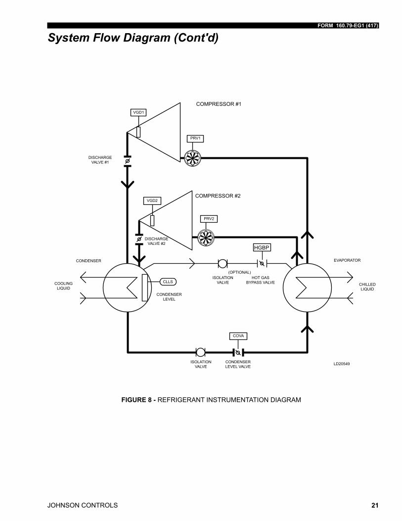
System Flow Diagram (Cont'd)
DISCHARGEVALVE #1
COMPRESSOR #1
COMPRESSOR #2
ISOLATION VALVE
CONDENSER LEVEL VALVE
ISOLATION VALVE
(OPTIONAL)HOT GAS
BYPASS VALVE
VGD1
PRV1
VGD2
PRV2
CLLS
CONDENSER LEVEL
COVA
CHILLED LIQUID
EVAPORATORCONDENSER
COOLING LIQUID
LD20549
DISCHARGEVALVE #2
FIGURE 8 - REFRIGERANT INSTRUMENTATION DIAGRAM
JOHNSON CONTROLS
FORM 160.79-EG1 (417)
22
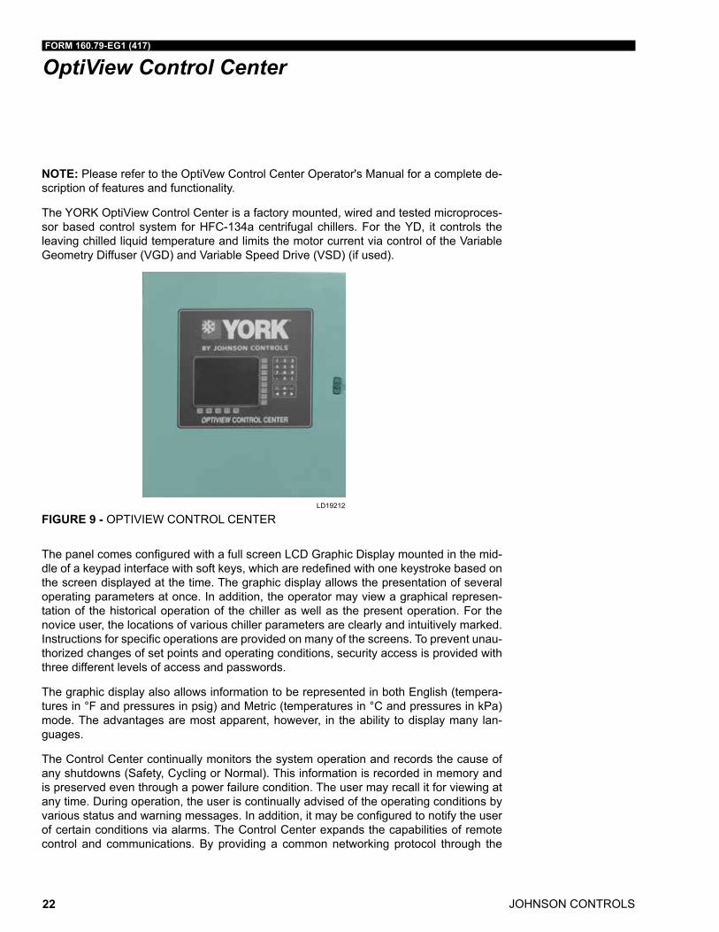
OptiView Control Center
NOTE: Please refer to the OptiVew Control Center Operator's Manual for a complete de-scription of features and functionality.
The YORK OptiView Control Center is a factory mounted, wired and tested microproces-sor based control system for HFC-134a centrifugal chillers. For the YD, it controls the leaving chilled liquid temperature and limits the motor current via control of the Variable Geometry Diffuser (VGD) and Variable Speed Drive (VSD) (if used).
LD19212
FIGURE 9 - OPTIVIEW CONTROL CENTER
The panel comes configured with a full screen LCD Graphic Display mounted in the mid-dle of a keypad interface with soft keys, which are redefined with one keystroke based on the screen displayed at the time. The graphic display allows the presentation of several operating parameters at once. In addition, the operator may view a graphical represen-tation of the historical operation of the chiller as well as the present operation. For the novice user, the locations of various chiller parameters are clearly and intuitively marked. Instructions for specific operations are provided on many of the screens. To prevent unau-thorized changes of set points and operating conditions, security access is provided with three different levels of access and passwords.
The graphic display also allows information to be represented in both English (tempera-tures in °F and pressures in psig) and Metric (temperatures in °C and pressures in kPa) mode. The advantages are most apparent, however, in the ability to display many lan-guages.
The Control Center continually monitors the system operation and records the cause of any shutdowns (Safety, Cycling or Normal). This information is recorded in memory and is preserved even through a power failure condition. The user may recall it for viewing at any time. During operation, the user is continually advised of the operating conditions by various status and warning messages. In addition, it may be configured to notify the user of certain conditions via alarms. The Control Center expands the capabilities of remote control and communications. By providing a common networking protocol through the
FORM 160.79-EG1 (417)
JOHNSON CONTROLS 23
OptiView Control Center (Cont'd)Building Automation System (BAS), YORK Chillers not only work well individually, but also as a team. This new protocol allows increased remote control of the chiller, as well as 24 hour performance monitoring via a remote site. In addition, compatibility is maintained with the present network of BAS communications. The chiller also maintains the standard digital remote capabilities as well. Both of these remote control capabilities allow for the standard Energy Management System (EMS) interface:
• Remote Run/Start
• Remote Leaving Chilled Liquid Temperature Setpoint adjustment (0 to 10VDC, 2 to 10VDC, 0 to 20mA or 4 to 20mA) or Pulse Width Modulation.
• Remote Current Limit Setpoint adjustment (0 to 10VDC, 2 to 10VDC, 0 to 20mA or 4 to 20mA or Pulse Width Modulation)
• Remote READY TO START Contacts
• Safety Shutdown Contacts
• Cycling Shutdown Contacts
The following are examples of the information displayed on some of the more important screens:
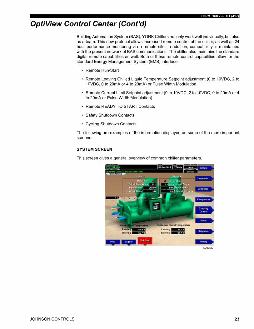
SYSTEM SCREEN
This screen gives a general overview of common chiller parameters.
LD20557
JOHNSON CONTROLS
FORM 160.79-EG1 (417)
24
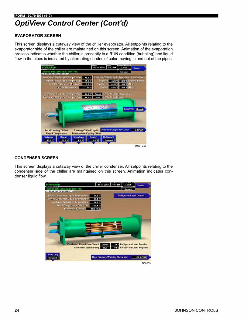
OptiView Control Center (Cont'd)EVAPORATOR SCREEN
This screen displays a cutaway view of the chiller evaporator. All setpoints relating to the evaporator side of the chiller are maintained on this screen. Animation of the evaporation process indicates whether the chiller is presently in a RUN condition (bubbling) and liquid flow in the pipes is indicated by alternating shades of color moving in and out of the pipes.
00301vipc
CONDENSER SCREEN
This screen displays a cutaway view of the chiller condenser. All setpoints relating to the condenser side of the chiller are maintained on this screen. Animation indicates con-denser liquid flow.
LD08603
FORM 160.79-EG1 (417)
JOHNSON CONTROLS 25
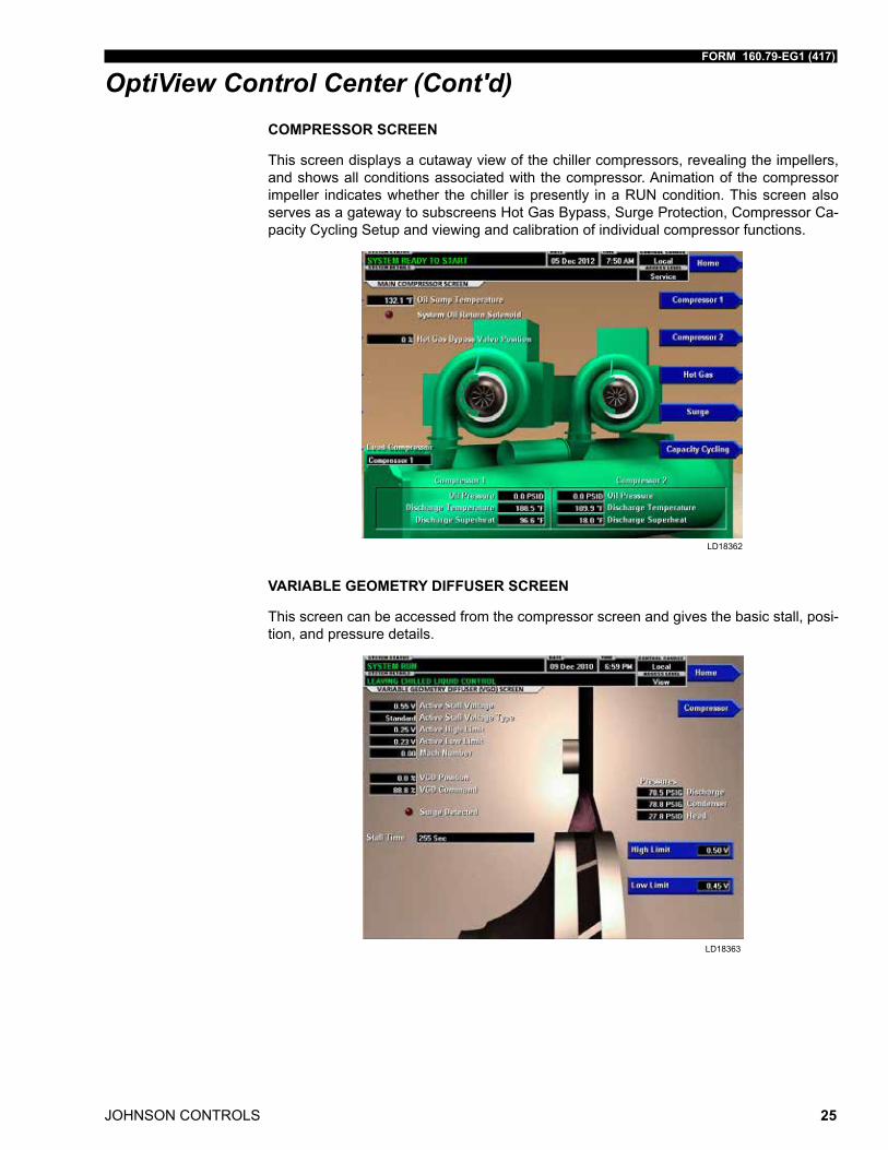
OptiView Control Center (Cont'd)COMPRESSOR SCREEN
This screen displays a cutaway view of the chiller compressors, revealing the impellers, and shows all conditions associated with the compressor. Animation of the compressor impeller indicates whether the chiller is presently in a RUN condition. This screen also serves as a gateway to subscreens Hot Gas Bypass, Surge Protection, Compressor Ca-pacity Cycling Setup and viewing and calibration of individual compressor functions.
LD18362
VARIABLE GEOMETRY DIFFUSER SCREEN
This screen can be accessed from the compressor screen and gives the basic stall, posi-tion, and pressure details.
LD18363
JOHNSON CONTROLS
FORM 160.79-EG1 (417)
26
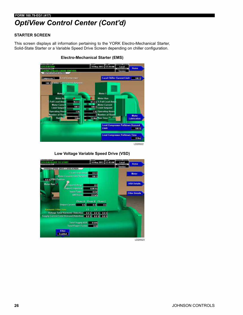
OptiView Control Center (Cont'd)STARTER SCREEN
This screen displays all information pertaining to the YORK Electro-Mechanical Starter, Solid-State Starter or a Variable Speed Drive Screen depending on chiller configuration.
Electro-Mechanical Starter (EMS)
LD20522
Low Voltage Variable Speed Drive (VSD)
LD20523
FORM 160.79-EG1 (417)
JOHNSON CONTROLS 27
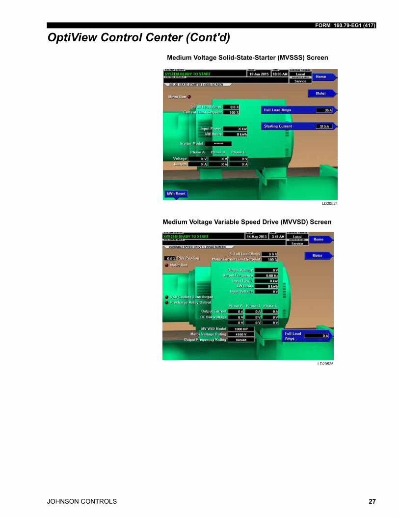
OptiView Control Center (Cont'd)Medium Voltage Solid-State-Starter (MVSSS) Screen
LD20524
Medium Voltage Variable Speed Drive (MVVSD) Screen
LD20525
JOHNSON CONTROLS
FORM 160.79-EG1 (417)
28
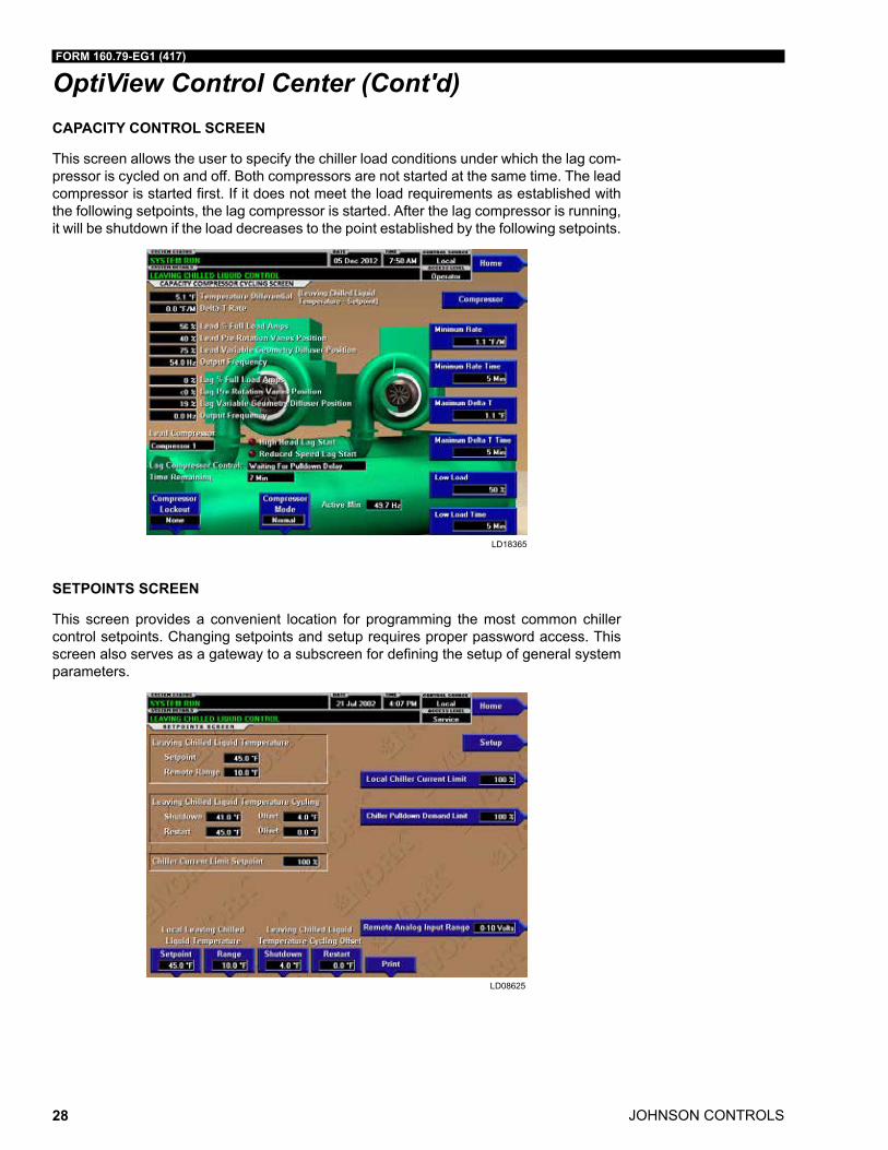
OptiView Control Center (Cont'd)CAPACITY CONTROL SCREEN
This screen allows the user to specify the chiller load conditions under which the lag com-pressor is cycled on and off. Both compressors are not started at the same time. The lead compressor is started first. If it does not meet the load requirements as established with the following setpoints, the lag compressor is started. After the lag compressor is running, it will be shutdown if the load decreases to the point established by the following setpoints.
LD18365
SETPOINTS SCREEN
This screen provides a convenient location for programming the most common chiller control setpoints. Changing setpoints and setup requires proper password access. This screen also serves as a gateway to a subscreen for defining the setup of general system parameters.
LD08625
FORM 160.79-EG1 (417)
JOHNSON CONTROLS 29
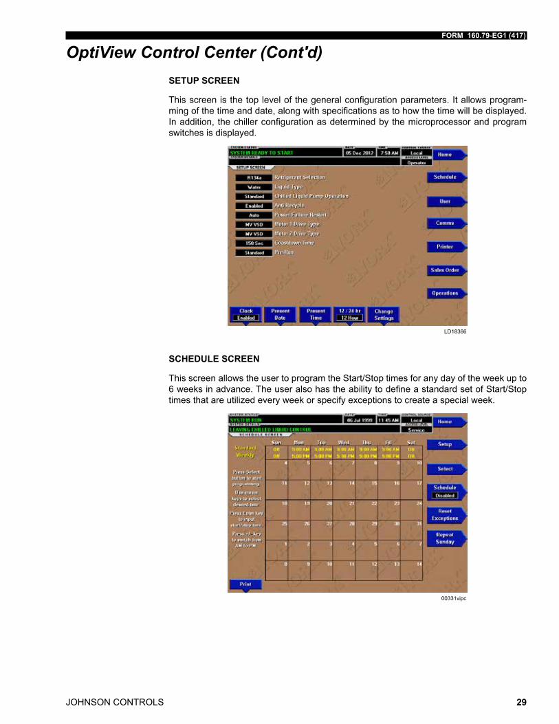
OptiView Control Center (Cont'd)SETUP SCREEN
This screen is the top level of the general configuration parameters. It allows program-ming of the time and date, along with specifications as to how the time will be displayed. In addition, the chiller configuration as determined by the microprocessor and program switches is displayed.
LD18366
SCHEDULE SCREEN
This screen allows the user to program the Start/Stop times for any day of the week up to 6 weeks in advance. The user also has the ability to define a standard set of Start/Stop times that are utilized every week or specify exceptions to create a special week.
00331vipc
JOHNSON CONTROLS
FORM 160.79-EG1 (417)
30
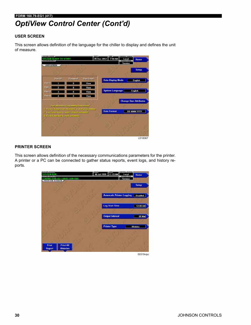
OptiView Control Center (Cont'd)USER SCREEN
This screen allows definition of the language for the chiller to display and defines the unit of measure.
LD18367
PRINTER SCREEN
This screen allows definition of the necessary communications parameters for the printer. A printer or a PC can be connected to gather status reports, event logs, and history re-ports.
00319vipc
FORM 160.79-EG1 (417)
JOHNSON CONTROLS 31
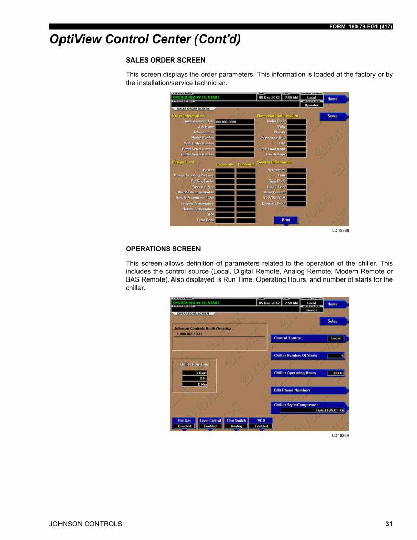
OptiView Control Center (Cont'd)SALES ORDER SCREEN
This screen displays the order parameters. This information is loaded at the factory or by the installation/service technician.
LD18368
OPERATIONS SCREEN
This screen allows definition of parameters related to the operation of the chiller. This includes the control source (Local, Digital Remote, Analog Remote, Modem Remote or BAS Remote). Also displayed is Run Time, Operating Hours, and number of starts for the chiller.
LD18369
JOHNSON CONTROLS
FORM 160.79-EG1 (417)
32
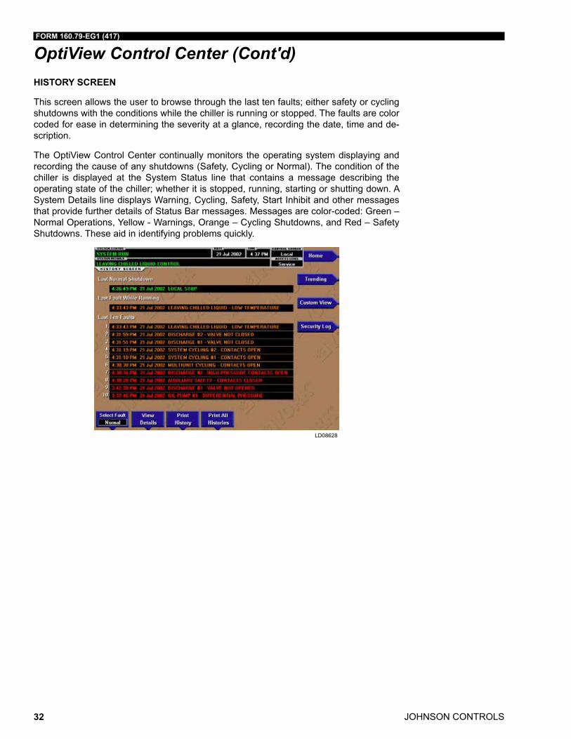
OptiView Control Center (Cont'd)HISTORY SCREEN
This screen allows the user to browse through the last ten faults; either safety or cycling shutdowns with the conditions while the chiller is running or stopped. The faults are color coded for ease in determining the severity at a glance, recording the date, time and de-scription.
The OptiView Control Center continually monitors the operating system displaying and recording the cause of any shutdowns (Safety, Cycling or Normal). The condition of the chiller is displayed at the System Status line that contains a message describing the operating state of the chiller; whether it is stopped, running, starting or shutting down. A System Details line displays Warning, Cycling, Safety, Start Inhibit and other messages that provide further details of Status Bar messages. Messages are color-coded: Green – Normal Operations, Yellow - Warnings, Orange – Cycling Shutdowns, and Red – Safety Shutdowns. These aid in identifying problems quickly.
LD08628
FORM 160.79-EG1 (417)
JOHNSON CONTROLS 33
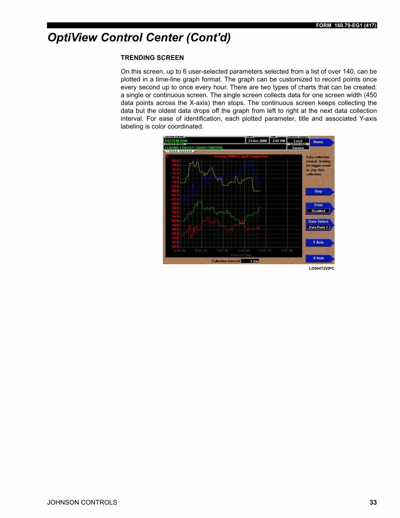
OptiView Control Center (Cont'd)TRENDING SCREEN
On this screen, up to 6 user-selected parameters selected from a list of over 140, can be plotted in a time-line graph format. The graph can be customized to record points once every second up to once every hour. There are two types of charts that can be created: a single or continuous screen. The single screen collects data for one screen width (450 data points across the X-axis) then stops. The continuous screen keeps collecting the data but the oldest data drops off the graph from left to right at the next data collection interval. For ease of identification, each plotted parameter, title and associated Y-axis labeling is color coordinated.
LD00472VIPC
JOHNSON CONTROLS
FORM 160.79-EG1 (417)
34
Starters and Drives
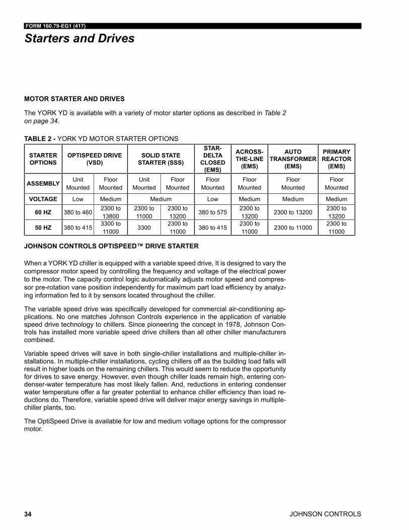
MOTOR STARTER AND DRIVES
The YORK YD is available with a variety of motor starter options as described in Table 2 on page 34.
TABLE 2 - YORK YD MOTOR STARTER OPTIONS
STARTER OPTIONS
OPTISPEED DRIVE (VSD)
SOLID STATE STARTER (SSS)
STAR-DELTA
CLOSED (EMS)
ACROSS-THE-LINE
(EMS)
AUTO TRANSFORMER
(EMS)
PRIMARY REACTOR
(EMS)
ASSEMBLY Unit Mounted
Floor Mounted
Unit Mounted
Floor Mounted
Floor Mounted
Floor Mounted
Floor Mounted
Floor Mounted
VOLTAGE Low Medium Medium Low Medium Medium Medium
60 HZ 380 to 4602300 to 13800
2300 to 11000
2300 to 13200
380 to 5752300 to 13200
2300 to 132002300 to 13200
50 HZ 380 to 4153300 to 11000
33002300 to 11000
380 to 4152300 to 11000
2300 to 110002300 to 11000
JOHNSON CONTROLS OPTISPEED™ DRIVE STARTER
When a YORK YD chiller is equipped with a variable speed drive, It is designed to vary the compressor motor speed by controlling the frequency and voltage of the electrical power to the motor. The capacity control logic automatically adjusts motor speed and compres-sor pre-rotation vane position independently for maximum part load efficiency by analyz-ing information fed to it by sensors located throughout the chiller.
The variable speed drive was specifically developed for commercial air-conditioning ap-plications. No one matches Johnson Controls experience in the application of variable speed drive technology to chillers. Since pioneering the concept in 1978, Johnson Con-trols has installed more variable speed drive chillers than all other chiller manufacturers combined.
Variable speed drives will save in both single-chiller installations and multiple-chiller in-stallations. In multiple-chiller installations, cycling chillers off as the building load falls will result in higher loads on the remaining chillers. This would seem to reduce the opportunity for drives to save energy. However, even though chiller loads remain high, entering con-denser-water temperature has most likely fallen. And, reductions in entering condenser water temperature offer a far greater potential to enhance chiller efficiency than load re-ductions do. Therefore, variable speed drive will deliver major energy savings in multiple-chiller plants, too.
The OptiSpeed Drive is available for low and medium voltage options for the compressor motor.
FORM 160.79-EG1 (417)
JOHNSON CONTROLS 35
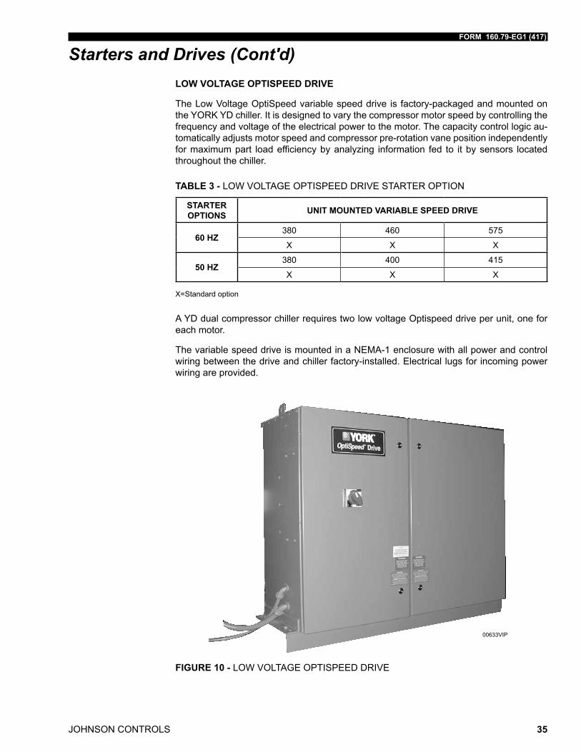
Starters and Drives (Cont'd)LOW VOLTAGE OPTISPEED DRIVE
The Low Voltage OptiSpeed variable speed drive is factory-packaged and mounted on the YORK YD chiller. It is designed to vary the compressor motor speed by controlling the frequency and voltage of the electrical power to the motor. The capacity control logic au-tomatically adjusts motor speed and compressor pre-rotation vane position independently for maximum part load efficiency by analyzing information fed to it by sensors located throughout the chiller.
TABLE 3 - LOW VOLTAGE OPTISPEED DRIVE STARTER OPTION
STARTER OPTIONS UNIT MOUNTED VARIABLE SPEED DRIVE
60 HZ380 460 575
X X X
50 HZ380 400 415
X X X
X=Standard option
A YD dual compressor chiller requires two low voltage Optispeed drive per unit, one for each motor.
The variable speed drive is mounted in a NEMA-1 enclosure with all power and control wiring between the drive and chiller factory-installed. Electrical lugs for incoming power wiring are provided.
FIGURE 10 - LOW VOLTAGE OPTISPEED DRIVE
00633VIP
JOHNSON CONTROLS
FORM 160.79-EG1 (417)
36
Starters and Drives (Cont'd)The variable speed drive provides automatic displacement power factor correction to 0.95 or better at all load conditions. Separate displacement power factor correction capacitors are not required. The displacement power factor is 0.98 or better when the optional har-monic filter is provided. See Table 4 on page 36 for additional advantages of variable speed drives.
Standard features include: a door interlocked lockable circuit breaker; UL/cUL listed ground fault protection; over-voltage and under-voltage protection; 3-phase sensing mo-tor over-current protection; single-phase protection; insensitive to phase rotation; over-temperature protection; digital readout at the OptiView Control Center of:
• Output Frequency
• Output Voltage
• 3-phase output current
• Input Power (kW)
• Self diagnostic service parameters
• Kilowatt-Hours (kWH)
An optional harmonic filter limits electrical power supply distortion from the variable speed drive to help the building comply with the guidelines of IEEE- 519 2014. The filter is unit mounted within the same NEMA-1 enclosure and is UL listed. The following digital readout is standard with the optional filter:
• Input kVA
• Total power-factor
• 3-phase input voltage
• 3-phase input current
• 3-phase input voltage total harmonic distortion (THD)
• 3-phase input current total demand distortion (TDD)
• Self-diagnostic service parameters
TABLE 4 - LOW VOLTAGE OPTISPEED VARIABLE SPEED DRIVE
STARTER TYPE ADVANTAGES
OPTISPEED VARIABLE
SPEED DRIVE (LOW
VOLTAGE)
- Lowest chiller life cycle through part load energy savings.-Application-specificdesignsenableefficient,preciseloadcontrolandseamlessintegration with equipment control panel and BAS.
- Soft start with input current less than full load current.- Smooth acceleration reduces stresses on motor and driveline.- Reduces compressor sound levels at most operating conditions.- Rugged and reliable with no moving parts.-IEEE-5192014compliantifusedwithanoptionalharmonicfilter.
FORM 160.79-EG1 (417)
JOHNSON CONTROLS 37
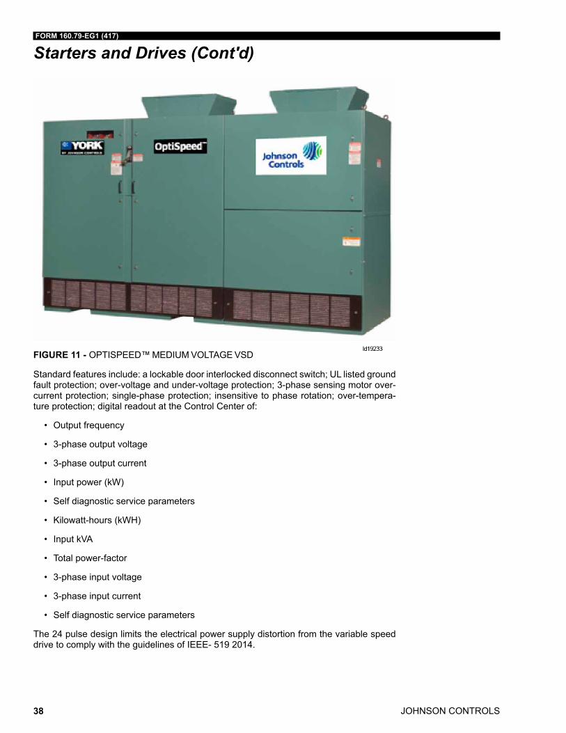
Starters and Drives (Cont'd)MEDIUM VOLTAGE OPTISPEED DRIVE
A variable speed drive is factory-packaged and configured for easy remote mounting. It is designed to vary the compressor motor speed by controlling the frequency and voltage of the electrical power to the motor. The capacity control logic automatically adjusts motor speed and compressor pre-rotation vane position independently for maximum part load efficiency by analyzing information fed to it by sensors located throughout the chiller.
TABLE 5 - MEDIUM VOLTAGE OPTISPEED DRIVE STARTER OPTION
STARTER OPTIONS FLOOR MOUNTED VARIABLE SPEED DRIVE
60 HZ2300 3300 4000 4160 6600 12470 13800
X X X X X X X
50 HZ3300 6600 10000 11000
X X X X
X= Standard option
A YD dual compressor chiller requires two medium voltage Optispeed drive per unit, one for each motor.
The variable speed drive is mounted in a NEMA-1 enclosure and comes with a certifica-tion label from a nationally recognized testing laboratory. The connection points between the drive and chiller are factory labeled. Electrical lugs for incoming power wiring are NOT provided.
The variable speed drive provides automatic displacement power factor correction to 0.98 or better at all load conditions. Separate displacement power factor correction capacitors are not required.
JOHNSON CONTROLS
FORM 160.79-EG1 (417)
38
Starters and Drives (Cont'd)
FIGURE 11 - OPTISPEED™ MEDIUM VOLTAGE VSD
Standard features include: a lockable door interlocked disconnect switch; UL listed ground fault protection; over-voltage and under-voltage protection; 3-phase sensing motor over-current protection; single-phase protection; insensitive to phase rotation; over-tempera-ture protection; digital readout at the Control Center of:
• Output frequency
• 3-phase output voltage
• 3-phase output current
• Input power (kW)
• Self diagnostic service parameters
• Kilowatt-hours (kWH)
• Input kVA
• Total power-factor
• 3-phase input voltage
• 3-phase input current
• Self diagnostic service parameters
The 24 pulse design limits the electrical power supply distortion from the variable speed drive to comply with the guidelines of IEEE- 519 2014.
FORM 160.79-EG1 (417)
JOHNSON CONTROLS 39
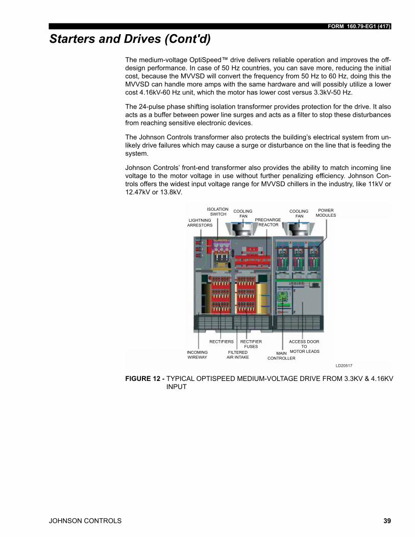
Starters and Drives (Cont'd)The medium-voltage OptiSpeed™ drive delivers reliable operation and improves the off-design performance. In case of 50 Hz countries, you can save more, reducing the initial cost, because the MVVSD will convert the frequency from 50 Hz to 60 Hz, doing this the MVVSD can handle more amps with the same hardware and will possibly utilize a lower cost 4.16kV-60 Hz unit, which the motor has lower cost versus 3.3kV-50 Hz.
The 24-pulse phase shifting isolation transformer provides protection for the drive. It also acts as a buffer between power line surges and acts as a filter to stop these disturbances from reaching sensitive electronic devices.
The Johnson Controls transformer also protects the building’s electrical system from un-likely drive failures which may cause a surge or disturbance on the line that is feeding the system.
Johnson Controls’ front-end transformer also provides the ability to match incoming line voltage to the motor voltage in use without further penalizing efficiency. Johnson Con-trols offers the widest input voltage range for MVVSD chillers in the industry, like 11kV or 12.47kV or 13.8kV.
LIGHTNINGARRESTORS
ISOLATION SWITCH
COOLING FAN
COOLING FAN
POWERMODULES
PRECHARGE REACTOR
INCOMINGWIREWAY
RECTIFIERS RECTIFIERFUSES
FILTEREDAIR INTAKE
MAINCONTROLLER
ACCESS DOOR TO
MOTOR LEADS
LD20517
FIGURE 12 - TYPICAL OPTISPEED MEDIUM-VOLTAGE DRIVE FROM 3.3KV & 4.16KV INPUT
JOHNSON CONTROLS
FORM 160.79-EG1 (417)
40
Starters and Drives (Cont'd)
CONTROLTRANSFORMER
INPUTTRANSFORMERS
MAINFUSES
PRE-CHARGEREACTOR
RECTIFIERRECTIFIERFUSES
FRONTVIEW
FILTEREDAIR INTAKE
ACCESS DOORTO
MOTOR LEADS
POWERMODULES
MAIN CONTROLLER
COOLINGFANS
ISOLATIONSWITCH
INCOMINGTERMINALS
MAINCONTACTOR
LD20518
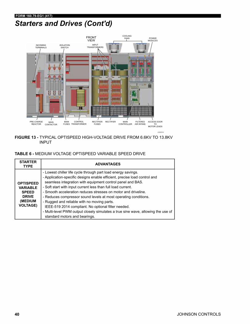
FIGURE 13 - TYPICAL OPTISPEED HIGH-VOLTAGE DRIVE FROM 6.6KV TO 13.8KV INPUT
TABLE 6 - MEDIUM VOLTAGE OPTISPEED VARIABLE SPEED DRIVE
STARTER TYPE ADVANTAGES
OPTISPEED VARIABLE
SPEED DRIVE
(MEDIUM VOLTAGE)
- Lowest chiller life cycle through part load energy savings.-Application-specificdesignsenableefficient,preciseloadcontrolandseamless integration with equipment control panel and BAS.
- Soft start with input current less than full load current.- Smooth acceleration reduces stresses on motor and driveline.- Reduces compressor sound levels at most operating conditions.- Rugged and reliable with no moving parts. IEEE-5192014compliant.Nooptionalfilterneeded.- Multi-level PWM output closely simulates a true sine wave, allowing the use of
standard motors and bearings.
FORM 160.79-EG1 (417)
JOHNSON CONTROLS 41
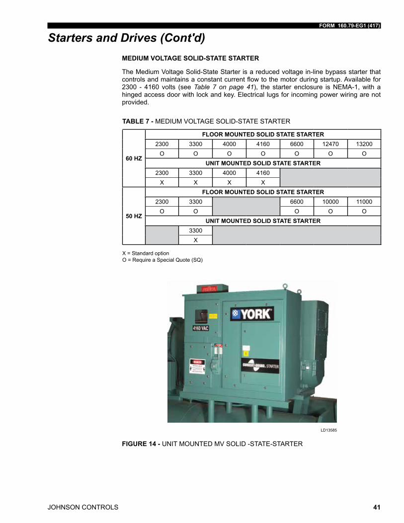
Starters and Drives (Cont'd)MEDIUM VOLTAGE SOLID-STATE STARTER
The Medium Voltage Solid-State Starter is a reduced voltage in-line bypass starter that controls and maintains a constant current flow to the motor during startup. Available for 2300 - 4160 volts (see Table 7 on page 41), the starter enclosure is NEMA-1, with a hinged access door with lock and key. Electrical lugs for incoming power wiring are not provided.
TABLE 7 - MEDIUM VOLTAGE SOLID-STATE STARTER
60 HZ
FLOOR MOUNTED SOLID STATE STARTER2300 3300 4000 4160 6600 12470 13200
O O O O O O OUNIT MOUNTED SOLID STATE STARTER
2300 3300 4000 4160X X X X
50 HZ
FLOOR MOUNTED SOLID STATE STARTER2300 3300 6600 10000 11000
O O O O OUNIT MOUNTED SOLID STATE STARTER
3300X
X = Standard optionO = Require a Special Quote (SQ)
FIGURE 14 - UNIT MOUNTED MV SOLID -STATE-STARTER
LD13585
JOHNSON CONTROLS
FORM 160.79-EG1 (417)
42
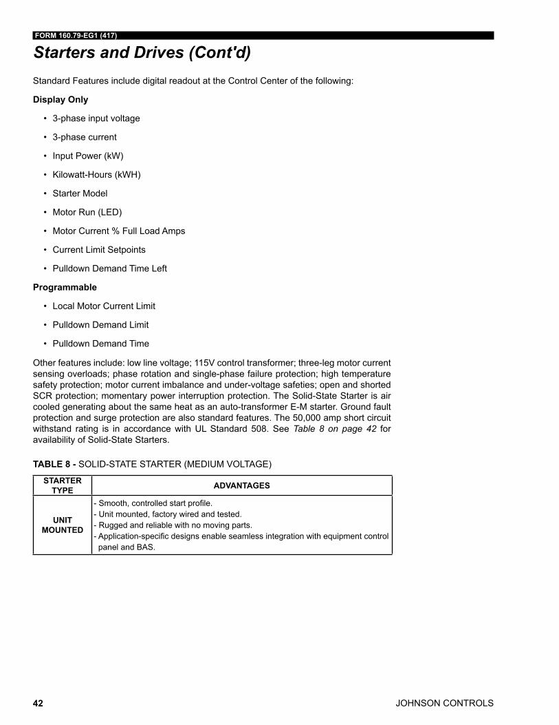
Starters and Drives (Cont'd)Standard Features include digital readout at the Control Center of the following:
Display Only
• 3-phase input voltage
• 3-phase current
• Input Power (kW)
• Kilowatt-Hours (kWH)
• Starter Model
• Motor Run (LED)
• Motor Current % Full Load Amps
• Current Limit Setpoints
• Pulldown Demand Time Left
Programmable
• Local Motor Current Limit
• Pulldown Demand Limit
• Pulldown Demand Time
Other features include: low line voltage; 115V control transformer; three-leg motor current sensing overloads; phase rotation and single-phase failure protection; high temperature safety protection; motor current imbalance and under-voltage safeties; open and shorted SCR protection; momentary power interruption protection. The Solid-State Starter is air cooled generating about the same heat as an auto-transformer E-M starter. Ground fault protection and surge protection are also standard features. The 50,000 amp short circuit withstand rating is in accordance with UL Standard 508. See Table 8 on page 42 for availability of Solid-State Starters.
TABLE 8 - SOLID-STATE STARTER (MEDIUM VOLTAGE)
STARTER TYPE ADVANTAGES
UNIT MOUNTED
-Smooth,controlledstartprofile.- Unit mounted, factory wired and tested.- Rugged and reliable with no moving parts.-Application-specificdesignsenableseamlessintegrationwithequipmentcontrolpanel and BAS.
FORM 160.79-EG1 (417)
JOHNSON CONTROLS 43
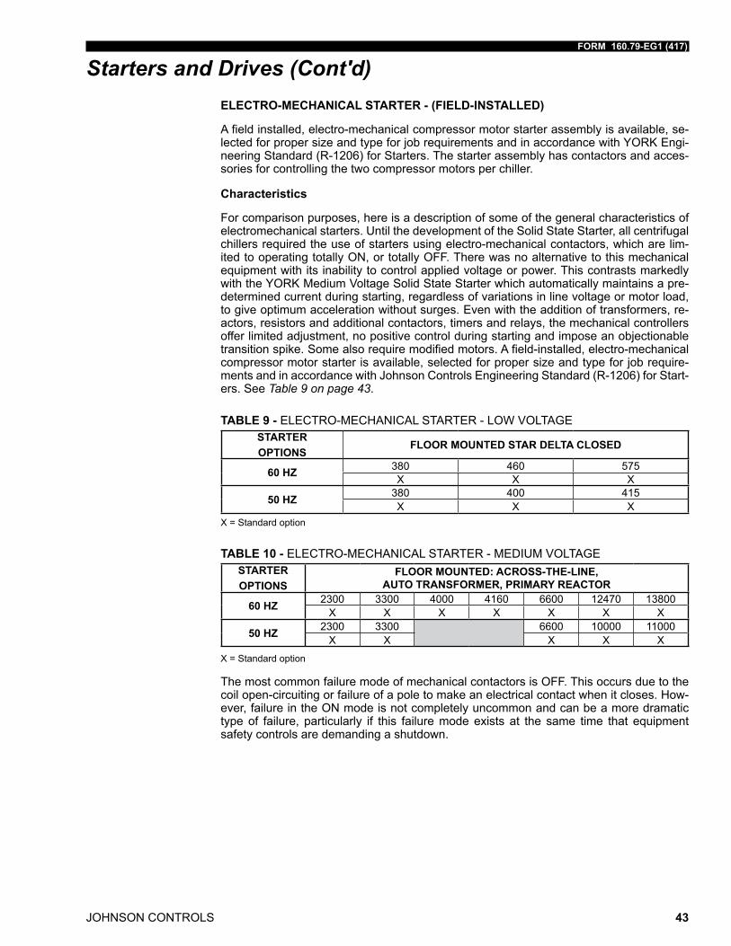
Starters and Drives (Cont'd)ELECTRO-MECHANICAL STARTER - (FIELD-INSTALLED)
A field installed, electro-mechanical compressor motor starter assembly is available, se-lected for proper size and type for job requirements and in accordance with YORK Engi-neering Standard (R-1206) for Starters. The starter assembly has contactors and acces-sories for controlling the two compressor motors per chiller.
Characteristics
For comparison purposes, here is a description of some of the general characteristics of electromechanical starters. Until the development of the Solid State Starter, all centrifugal chillers required the use of starters using electro-mechanical contactors, which are lim-ited to operating totally ON, or totally OFF. There was no alternative to this mechanical equipment with its inability to control applied voltage or power. This contrasts markedly with the YORK Medium Voltage Solid State Starter which automatically maintains a pre-determined current during starting, regardless of variations in line voltage or motor load, to give optimum acceleration without surges. Even with the addition of transformers, re-actors, resistors and additional contactors, timers and relays, the mechanical controllers offer limited adjustment, no positive control during starting and impose an objectionable transition spike. Some also require modified motors. A field-installed, electro-mechanical compressor motor starter is available, selected for proper size and type for job require-ments and in accordance with Johnson Controls Engineering Standard (R-1206) for Start-ers. See Table 9 on page 43.
TABLE 9 - ELECTRO-MECHANICAL STARTER - LOW VOLTAGESTARTER OPTIONS
FLOOR MOUNTED STAR DELTA CLOSED
60 HZ 380 460 575X X X
50 HZ 380 400 415X X X
X = Standard option
TABLE 10 - ELECTRO-MECHANICAL STARTER - MEDIUM VOLTAGESTARTER OPTIONS
FLOOR MOUNTED: ACROSS-THE-LINE, AUTO TRANSFORMER, PRIMARY REACTOR
60 HZ 2300 3300 4000 4160 6600 12470 13800X X X X X X X
50 HZ 2300 3300 6600 10000 11000X X X X X
X = Standard option
The most common failure mode of mechanical contactors is OFF. This occurs due to the coil open-circuiting or failure of a pole to make an electrical contact when it closes. How-ever, failure in the ON mode is not completely uncommon and can be a more dramatic type of failure, particularly if this failure mode exists at the same time that equipment safety controls are demanding a shutdown.
JOHNSON CONTROLS
FORM 160.79-EG1 (417)
44
Starters and Drives (Cont'd)When contacts are “made,” the current builds up to its maximum value from zero, but when contacts are separated the current tends to flow through the gap thus formed and causes an arc. This arcing depends upon the voltage between the separating contacts. For medium voltage starters, the use of vacuum contactors mitigates this problem some-what by providing an environment to extinguish the arc. In the alternating current circuit, the separation of contacts may take place when the current is zero or maximum or at any value in between. An alternating current passes through zero and reverses its polarity twice during each cycle. If two or more contacts, one in each leg of a polyphase system, are separated simultaneously, the current values in each will vary. In a three-phase sys-tem, if one contact has zero current when opened, the other two contacts will have 86.6% of their maximum values, as an example. Additionally, when inductive circuits are broken, the voltage is increased at the contacts due to the counter (induced) EMF of the circuit. The instant the contacts separate, the voltage between them momentarily rises from zero to the maximum of the circuit, or higher if inductance is present in the circuit. In practice, every time the contacts close, they bounce. When they bounce, they arc. The arcing occurs as the contacts make or break may result in rapid and excessive erosion of the contacts, causing prematurely short contact life.
YORK chillers are designed for use with the following types of electro-mechanical start-ers, here briefly described.
Across-the-Line (ACL): These are the simplest and lowest-cost starters available. They apply full voltage to the three motor leads at the instant of starting. Since inrush is 100% of LRA and starting torque is 100%, this is the roughest type of starting on the motor and drive- line. In physical size, the ACL is the smallest of electro-mechanical starters and there is no transition surge. In most areas, utilities will not permit the use of this type of starter for chiller-size motors because of their large current draw on startup.
Auto Transformer (AT): These starters are reduced-voltage starters. Transformers are used to step down the voltage to the motor during startup. The result is reduced inrush current and starting torque at the level of 42% or 64% depending upon whether 65% or 80% voltage taps are used. They provide closed transition (with three-lead motors) with reduced line disturbance.
Star-Delta: During startup, the motor is connected in a Star or Wye configuration. This reduces the voltage to the motor stator by a factor of three. This 1/3 voltage results in 1/3 current into the motor at start and 1/3 torque to the shaft. Centrifugal compressor starting torque requirements are low enough to allow the motor to start at 1/3 of full load torque.
Primary Reactor: These starters are reduced-voltage starters. Transformers are used to step down the volt age to the motor during startup. The result is reduced starting torque at the level of 42% or 64%, but with reduced inrush current of 65% or 80% depending upon whether 65% or 80% voltage taps are used. They provide closed transition (with three-lead motors) with reduced line disturbance.
FORM 160.79-EG1 (417)
JOHNSON CONTROLS 45
Accessories and Modifications
BAS REMOTE CONTROL
A communication interface permitting an exchange of chiller data with a BACnet MS/TP, Modbus RTU, LONworks or N2 Metasys network is available by means of an optional SC-EQUIP board (Smart Chiller – Equipment Board) or E-Link® board gateway. The Johnson Controls Gateway mounts conveniently inside the OptiView panel and allows remote BAS networks to monitor values and issue commands to the chiller to control operation.
DUAL OIL FILTERS
Dual oil filters with a multi-port changeover valve and manual shutoff valves are optional to allow changing of one filter while the chiller is operating.
FACTORY INSULATION OF EVAPORATOR
Factory-applied thermal insulation of the flexible, closed-cell plastic type, 3/4" (19 mm) thick is attached with va por-proof cement to the evaporator shell, tube sheets, suction connection, and (as necessary) to the auxiliary tubing. Not included is the insulation of wa-terboxes and nozzles. This insulation will nor mally prevent condensation in environments with relative humidities up to 75% and dry bulb temperatures ranging from 50° to 90°F (10° to 32.2°C). 1-1/2" (38 mm) thick insulation is also available for relative humidities up to 90% and dry bulb temperatures ranging from 50° to 90°F (10° to 32.2°C).
KNOCK-DOWN SHIPMENT
All YD Chillers can be shipped knocked down into major subassemblies (evaporator, con-denser, driveline, etc.) as required to rig into tight spaces. This is particularly convenient for existing buildings where equipment room access does not allow rigging a factory pack-aged chiller.
HIGH AMBIENT TEMPERATURE
Chiller modifications are available to allow for installation in high ambients of up to 122°F (50°C). Special drive motors are required above 104°F (40°C). H9 and K compressor evaporator design pressures must be increased for ambient temperatures above 112.8°F (45°C). The OptiView panel and low voltage VSD are suited for 122°F (50°C) ambient. Low and medium voltage Solid-State Starters must be derated and/or modified above 110°F (43.3°C). The free standing MVVSD option must be derated above its standard 104°F (40°C) limit.
HIGH VOLTAGE MOTORS
High voltage motors (6000V/60 Hz to 13800V/60 Hz and 6000V/50 Hz to 11000V/50 Hz) are available for YD units.
HINGES AND DAVIT ARMS
Hinges and/or davit arms are available to ease serviceability. Hinges on the nozzle end of a compact waterbox still require that facility water piping be disconnected.
JOHNSON CONTROLS
FORM 160.79-EG1 (417)
46
Accessories and Modifications (Cont'd)MARINE WATERBOXES
Marine waterboxes allow service access for cleaning of the heat exchanger tubes without the need to break the water piping. Bolted-on covers are arranged for conven ient access. ANSI/AWWA C-606 couplings nozzle connections are standard; flanges are optional. Ma-rine waterboxes are available for condenser and/or evaporator.
REFRIGERANT STORAGE/RECYCLING SYSTEM
A refrigerant storage/recycling system is a self-con tained package consisting of a refriger-ant compressor with oil separator, storage receiver, water-cooled con denser, filter drier and necessary valves and hoses to remove, replace and distill refrigerant. All necessary controls and safety devices are a permanent part of the system.
SPECIAL MOTORS ENCLOSURES
There are job applications, primarily in manufacturing plants, and process applications, where more motor protection is required. Listed below are several alternatives. NOTE: Chiller certification to UL by a third party could be affected. Contact a Johnson Controls sales office for a specific selection.
Weather-Protected Type I Motors (WP-I) - A Weather-Protected Type I motor is an open machine with its ventilating passages constructed to prevent the passage of a cylindri-cal rod 3/4” (19 mm) in diameter. This affords protection against intrusion of rodents and some types of debris. These are regularly used in the pulp industry and where grime is present.
Weather-Protected Type II Motors (WP-II) - A Weather-Protected Type II motor has, in addition to the enclosure defined for Weather-Protected Type I motor, ventilating passag-es at both intake and exhaust so arranged that high-velocity air and air-borne particles, blown into the motor, can be discharged without entering the internal ventilating passages leading directly to the electric parts of the machine itself. Space heaters are required with WP-II.
Totally Enclosed Fan-Cooled Motors (TEFC) - TEFC motors are used where the loca-tion is extremely dirty, dusty, or wet, both indoors and outdoors. A totally enclosed fan-cooled unit is enclosed to prevent the free exchange of air between the inside and outside of the case but not sufficiently enclosed as to be termed air-tight. It is air-cooled by means of a fully guarded fan blowing cooling air over the outside of the motor. The fan is exter-nally mounted on the motor shaft.
Totally Enclosed Air-to-Air Cooled (TEAAC) - TEAAC motors are used when the envi-ronment is dirty or corrosive. A TEAAC motor is a totally enclosed motor, cooled by circu-lating the internal air through an air-to-air heat exchanger.
Totally Enclosed Water-to-Air Cooled (TEWAC) - TEWAC motors are used when the environment is dirty or corrosive, in hazardous areas, or where minimum noise levels are required. A TEWAC motor is a totally enclosed machine which is cooled by circulat-ing internal air which, in turn, is cooled by circulating water. It is provided with an internal water-cooled heat exchanger for cooling the internal air and fans, integral with the rotor shaft for circulating the internal air.
FORM 160.79-EG1 (417)
JOHNSON CONTROLS 47
SPRING ISOLATION MOUNTING
Spring isolation mounting is available instead of standard isolation mounting pads when desired. Four level-adjusting, spring-type vibration isolator assemblies with non-skid pads are provided for field installation. Isolators are designed for 1" (25 mm) deflection.
TUBE AND/OR TUBE SHEET MATERIALS AND/OR WATERBOX COATING
Alternate copper-nickel or titanium tubes can be provided in lieu of standard copper for condenser and/or evaporator for protection against aggressive water conditions. Tube sheets may be of the clad type. Epoxy or ceramic coating may be applied to waterboxes or to tubesheet and waterboxes.
WATER FLANGES
Four 150 psig. (1.14 MPa) ANSI raised-face flanges for condenser and evaporator water connections, are factory welded to water nozzles. Companion flanges, bolts, nuts and gaskets are not included.
Accessories and Modifications (Cont'd)
JOHNSON CONTROLS
FORM 160.79-EG1 (417)
48
Application Data
The following discussion is a user’s guide in the applica tion and installation of YD chillers to ensure the reliable, trouble-free life for which this equipment was designed. While this guide is directed towards normal, water-chilling applications, the Johnson Controls sales repre sentative can provide complete recommendations on other types of applications.
BRINE APPLICATIONS
Various types of brine can be used in both the evaporator and condenser in lieu of water. The OptiView panel is programmed in the factory to allow extending the evaporator leav-ing brine temperature setpoint below 36°F (2.2°C). The low evaporator pressure cutout is factory programmed to the appropriate value depending on the percentage concentration and type of brine solution.
When the chiller is not running, brine should not be flowing through the evaporator. How-ever, if there is brine flowing through the evaporator, there must be flow through the con-denser to prevent tubes from freezing. In brine applications, the condenser pump control will close when the condenser saturation temperature reaches 35°F (1.7°C) and the pump will shut off when the temperature increases to 40°F (4.4°C). This is applicable if tied to the condenser pump control.
LOCATION
YD chillers are virtually vibration free and may generally be located at any level in a build-ing where the construction will support the total system operating weight.
The unit site must be a floor, mounting pad or foundation which is level within 1/4" (6.4 mm) and capable of supporting the operating weight of the unit.
Sufficient clearance to permit normal service and main tenance work should be provided all around and above the unit. Additional space should be provided at one end of the unit to permit cleaning of evaporator and condenser tubes as required. A doorway or other properly located opening may be used.
The chiller should be installed in an indoor location where temperatures range from 40°F to 104°F (4.4°C to 40°C). The dew point temperature in the equipment room must be be-low the entering condenser water temperature to prevent condensing water vapor inside of the solid state starter or low voltage variable speed drive cabinet (if applicable). Applica-tions using cooling sources other than evaporative or closed loop air exchange methods need to request a factory-supplied temperature control valve to prevent condensation inside the solid state starter or low voltage variable speed drive cabinet (if applicable). Other areas susceptible to water vapor condensate are outside of the condenser shell and condenser waterboxes. Example applications include when the condenser water comes from chilled water, wells, river, or other low temperature fluids.
FORM 160.79-EG1 (417)
JOHNSON CONTROLS 49
Application Data (Cont'd)MULTIPLE UNITS
Selection – Many applications require multiple units to meet the total capacity require-ments as well as to provide flexibility and some degree of protection against equipment shutdown. There are several common unit arrangements for this type of application. The YD chiller has been designed to be readily adapted to the requirements of these various arrangements.
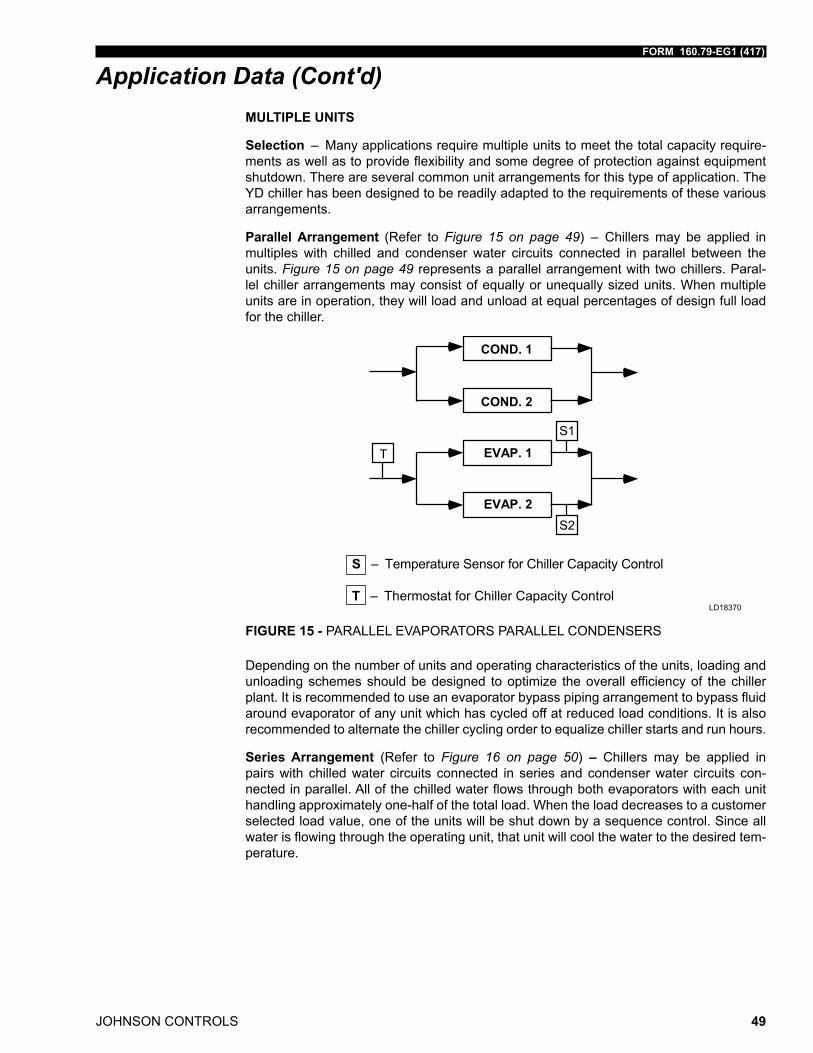
Parallel Arrangement (Refer to Figure 15 on page 49) – Chillers may be applied in multiples with chilled and condenser water circuits connected in parallel between the units. Figure 15 on page 49 represents a parallel arrangement with two chillers. Paral-lel chiller arrangements may consist of equally or unequally sized units. When multiple units are in operation, they will load and unload at equal percentages of design full load for the chiller.
�������
�������
�������
�������
�
��
��
S – Temperature Sensor for Chiller Capacity Control
T – Thermostat for Chiller Capacity Control
FIGURE 15 - PARALLEL EVAPORATORS PARALLEL CONDENSERS
LD18370
Depending on the number of units and operating characteristics of the units, loading and unloading schemes should be designed to optimize the overall efficiency of the chiller plant. It is recommended to use an evaporator bypass piping arrangement to bypass fluid around evaporator of any unit which has cycled off at reduced load conditions. It is also recommended to alternate the chiller cycling order to equalize chiller starts and run hours.
Series Arrangement (Refer to Figure 16 on page 50) – Chillers may be applied in pairs with chilled water circuits connected in series and condenser water circuits con-nected in parallel. All of the chilled water flows through both evaporators with each unit handling approximately one-half of the total load. When the load decreases to a customer selected load value, one of the units will be shut down by a sequence control. Since all water is flowing through the operating unit, that unit will cool the water to the desired tem-perature.
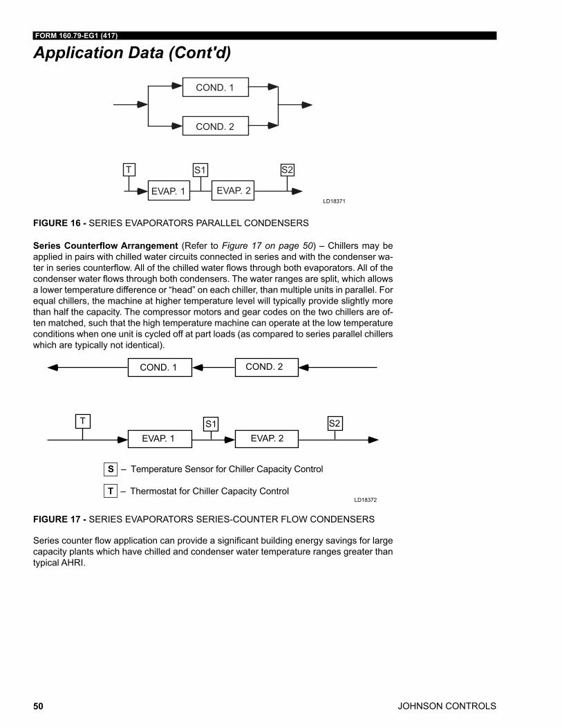
JOHNSON CONTROLS
FORM 160.79-EG1 (417)
50
Application Data (Cont'd)
EVAP. 1 EVAP. 2
T S1 S2
COND. 1
COND. 2
FIGURE 16 - SERIES EVAPORATORS PARALLEL CONDENSERS
LD18371
Series Counterflow Arrangement (Refer to Figure 17 on page 50) – Chillers may be applied in pairs with chilled water circuits connected in series and with the condenser wa-ter in series counterflow. All of the chilled water flows through both evaporators. All of the condenser water flows through both condensers. The water ranges are split, which allows a lower temperature difference or “head” on each chiller, than multiple units in parallel. For equal chillers, the machine at higher temperature level will typically provide slightly more than half the capacity. The compressor motors and gear codes on the two chillers are of-ten matched, such that the high temperature machine can operate at the low temperature conditions when one unit is cycled off at part loads (as compared to series parallel chillers which are typically not identical).
FIGURE 17 - SERIES EVAPORATORS SERIES-COUNTER FLOW CONDENSERS
LD18372
COND. 1 COND. 2
EVAP. 1 EVAP. 2
T S2
S – Temperature Sensor for Chiller Capacity Control
T – Thermostat for Chiller Capacity Control
Series counter flow application can provide a significant building energy savings for large capacity plants which have chilled and condenser water temperature ranges greater than typical AHRI.
FORM 160.79-EG1 (417)
JOHNSON CONTROLS 51
Application Data (Cont'd)REFRIGERANT RELIEF PIPING
Each chiller is equipped with dual relief valves on the condenser and a single relief valve on the evaporator. The dual relief valves on the condenser are redundant and allow changing of either valve while the unit is fully charged. The purpose of the relief valves is to quickly relieve excess pressure of the refrigerant charge to the atmosphere, as a safety precaution in the event of an emergency such as fire. They are set to relieve at an internal pressure as noted on the pressure vessel data plate, and are provided in accordance with ASHRAE 15 safety code and ASME or applicable pressure vessel code.
Sized to the requirements of applicable codes, a vent line must run from the relief de-vice to the outside of the building. This refrigerant relief piping must include a cleanable, vertical-leg dirt trap to catch vent-stack con densation. Vent piping must be arranged to avoid im posing a strain on the relief connection and should include at least one flexible connection.
SOUND AND VIBRATION CONSIDERATIONS
A YD chiller is not a source of objectionable sound and vibration in normal air conditioning applica tions. Neoprene isolation mounts are furnished as standard with each unit. Op-tional level-adjusting spring isolator assemblies designed for 1” (25 mm) static deflection are available from Johnson Controls.
YD chiller sound pressure level ratings will be furnished on request.
Control of sound and vibration transmission must be taken into account in the equipment room construction as well as in the selection and installation of the equip ment.
THERMAL INSULATION
No appreciable operating economy can be achieved by thermally insulating the chiller. However, the chiller’s cold surfaces should be insulated with a vapor barrier insulation sufficient to prevent condensation. A chiller can be factory insulated with 3/4” (19 mm) or 1-1/2” (38 mm) thick insu lation, as an option. This insulation will normally pre vent con-densation in environments with dry bulb temperatures of 50°F to 90°F (10°C to 32°C) and relative humidities up to 75% [3/4” (19 mm) thickness] or 90% [1-1/2” (38 mm) thickness]. The insulation is painted and the surface is flexible and reasonably resistant to wear. It is intended for a chiller installed indoors and, therefore, no protective covering of the insula-tion is usually required. If insulation is applied to the waterboxes at the job site, it must be removable to permit access to the tubes for routine maintenance.
VENTILATION
The ASHRAE Standard 15 Safety Code for Mechanical Refrigeration requires that all ma-chinery rooms be vented to the outdoors utilizing mechanical ventilation by one or more power-driven fans. This standard, plus National Fire Protection Association Standard 90A, state, local and any other related codes should be reviewed for specific requirements. Since the YD chiller mo tors are air-cooled, ventilation should allow for the removal of heat from the motors.
In addition, the ASHRAE Standard 15 requires a refrigerant vapor detector to be em-ployed for all refrigerants. It is to be located in an area where refrigerant from a leak would be likely to concentrate. An alarm is to be activated and the mechanical ventilation started at a value no greater than the TLV (Threshold Limit Value) of the refrigerant.
JOHNSON CONTROLS
FORM 160.79-EG1 (417)
52
Application Data (Cont'd)WATER CIRCUITS
Flow Rate – For normal water chilling duty, evaporator and condenser flow rates are permitted at water velocity levels in the heat exchangers tubes of between 3 ft/sec and 12 ft/sec (0.91 m/s and 3.66 m/s) for constant flow applications. Variable flow applications are possible, and initial chiller selections should be made accordingly to allow proper range of flow while maintaining the minimum velocity indicated at the certified rating for the unit. Variable flow in the condenser is not recommended, as it generally raises the energy con-sumption of the system by keeping the condenser pressure high in the chiller. Additionally, the rate of fouling in the condenser will increase at lower water velocities associated with variable flow, raising system maintenance costs. Cooling towers typically have narrow ranges of operation with respect to flow rates, and will be more effective with full design flow. Refer to Table 11 on page 55 for flow limits.
Temperature Ranges – For normal water chilling duty, leaving chilled water tempera-tures may be selected between 38°F (3.3°C) 36°F (2.2°C) with Smart Freeze enabled] and 70°F (21.1°C) to obtain temperature deltas between entering chilled and leaving chilled water temperature of 3°F up to 30°F (1.7°C and 16.7°C).
Water Quality – The practical and economical applica tion of liquid chillers requires that the quality of the water supply for the condenser and evaporator be analyzed by a water treatment specialist. Water quality may affect the performance of any chiller through cor-rosion, deposition of heat-resistant scale, sedimentation or organic growth. These will degrade chiller performance and increase operat ing and maintenance costs. Normally, performance may be maintained by corrective water treatment and periodic cleaning of tubes. If water conditions exist which cannot be corrected by proper water treatment, it may be nec essary to provide a larger allowance for fouling, and/or to specify special ma-terials of construction. See the Application Guide 160.00-AD5 for more details.
General Piping – All chilled water and condenser water piping should be designed and installed in accordance with accepted piping practice. Chilled water and con denser water pumps should be located to discharge through the chiller to assure positive pressure and flow through the unit. Piping should include offsets to provide flexibility and should be arranged to prevent drainage of water from the evaporator and condenser when the pumps are shut off. Piping should be adequately supported and braced independently of the chiller to avoid the imposition of strain on chiller components. Hangers must allow for alignment of the pipe. Isolators in the piping and in the hangers are highly desirable in achiev ing sound and vibration control.
Convenience Considerations – To facilitate the performance of routine maintenance work, some or all of the following steps may be taken by the pur chaser. Evaporator and condenser waterboxes are equipped with plugged vent and drain connections. If desired, vent and drain valves may be installed with or without piping to an open drain. Pressure gauges with stop-cocks and stop valves may be installed in the inlets and outlets of the condenser and chilled water line as close as possible to the chiller. An overhead monorail or beam may be used to facilitate servicing.
Connections – The standard chiller is designed for 150 psig (1.14 MPa) design working pressure in both the chilled water and condenser water circuits. The connections (water nozzles) to these circuits are furnished with grooves to ANSI/AWWA C 606 Standard for grooved and shouldered joints. Piping should be arranged for ease of disassembly at the unit for tube cleaning. All water piping should be thoroughly cleaned of all dirt and debris before final connections are made to the chiller.
FORM 160.79-EG1 (417)
JOHNSON CONTROLS 53
Application Data (Cont'd)Fluid Strainer – A fluid strainer with perforated holes no larger than 1/8” (3.2 mm) must be field-installed in the chilled fluid inlet line as close as possible to the chiller. If located close enough to the chiller, the chilled fluid pump may be protected by the same strainer. The strain-er is to protect the chiller from debris or objects which could block flow through individual heat exchanger tubes. A reduction in flow through tubes could seriously impair the chiller perfor-mance or even result in tube freeze up. A thermal-type flow switch is factory installed in the evaporator nozzle and connected to the OptiView panel, which assures adequate chilled fluid flow during operation.
Condenser Fluid – The chiller is engineered for maxi mum efficiency at both design and part-load operation by taking advantage of the colder cooling tower fluid temperatures which naturally occur during the winter months and off-design conditions. Appreciable power sav-ings are realized from these reduced heads.
The unique design of YORK YD centrifugal chillers in the HVAC industry allows cold con-denser fluid starts, without the nuisance trips experienced by most other manufacturers, as detailed below:
1. The condenser shell is higher than the evaporator, thus when the chiller is not in operation, gravity moves refrigerant from the condenser into the evaporator. On start-up, the compressor begins pumping refrigerant gas from the evaporator into the condenser and thus builds head pressure.
2. The butterfly type liquid expansion valve (variable orifice valve) is controlled bythe condenser liquid level at the sub-cooler inlet. As that level increases, the valve wouldbedrivenopentoallowmaximumrefrigerantflow.
3. YORK YD centrifugal chillers start-up with vanes closed, which reduces the amount of refrigerant gas pumped out of the evaporator over time.
4. The control system is set to stop the vanes from further opening if the evaporator fluidtemperatureachieves1°F(0.6°C)abovethetripset-pointforlowwatertem-perature cut-out, typically 4°F (2.2°C) below set point.
At initial start-up, entering condenser water temperature may be 25°F (13.9°C) colder than standby chilled water temperature, but the minimum temperature should be above the freez-ing point of the chilled liquid.
Handling cold condenser fluid at the onset of changeover from free cooling with tower/heat exchangers is often a realistic requirement. The chiller will start and continue to operate be-cause pressure differential increases quickly, thus preventing nuisance trips on low evaporator pressure usually caused by: system depression, refrigerant stack-up in the condenser, and starvation of the evaporator.
For continuous operation, the minimum entering condenser fluid temperature for both full and part load conditions is provided by the following equation:
English
Min. ECWT = LCHWT – C RANGE + 5°F + 12 ( %Load )100
JOHNSON CONTROLS
FORM 160.79-EG1 (417)
54
Application Data (Cont'd)SIMin. ECWT = LCHWT – C RANGE + 2.8°C + 6.6 ( %Load )100
where:
ECFT = entering condensing fluid temperature
LCHFT = leaving chilled fluid temperature
COND.RANGE = leaving condenser fluid temperature - entering condenser
Fluid temperature at given load condition.
Examples:
a. 2000 TR (7032 kW) chiller
b. 44°F (6.7°C) leaving chilled fluid temperature
c. 85/94.3°F (29.4/34.6°C) condenser fluid temperature range @ full load
English Example
At full load:
Min. ECFT = 44 – (94.3 - 85) + 5 + 12100
= 44 – 9.3 + 5 + 12 =100
Min. ECFT = 51.7 °F
At 20% load:
Min. ECFT = 44 – (87 - 85) + 5 + 1220
= 44 – 2 + 5 + 2.4 =100
Min. ECFT = 49.4 °F
SI Example
At full load:
Min. ECFT = 6.7 – (34.6 - 29.4) + 2.8 + 6.6100
= 6.7 – 5.2 + 2.8 + 6.6 =100
Min. ECFT = 10.9°C
At 20% load:
Min. ECFT = 6.7 – (30.6 - 29.4) + 2.8 + 6.620
= 6.7 – 1.2 + 2.8 + 1.3 =100
Min. ECFT = 9.6 °C
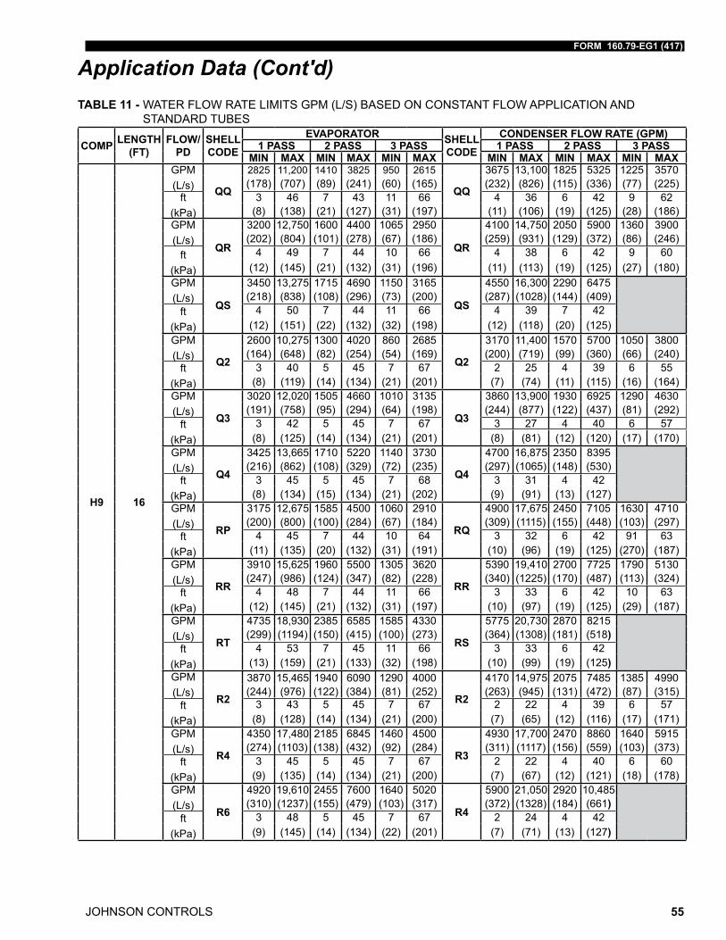
FORM 160.79-EG1 (417)
JOHNSON CONTROLS 55
Application Data (Cont'd)TABLE 11 - WATER FLOW RATE LIMITS GPM (L/S) BASED ON CONSTANT FLOW APPLICATION AND
STANDARD TUBES
COMP LENGTH (FT)
FLOW/PD
SHELL CODE
EVAPORATOR SHELL CODE
CONDENSER FLOW RATE (GPM)1 PASS 2 PASS 3 PASS 1 PASS 2 PASS 3 PASS
MIN MAX MIN MAX MIN MAX MIN MAX MIN MAX MIN MAX
H9 16
GPM(L/s) QQ
2825 11,200 1410 3825 950 2615
3675 13,100 1825 5325 1225 3570 (178) (707) (89) (241) (60) (165) (232) (826) (115) (336) (77) (225)
ft(kPa)
3 46 7 43 11 66 4 36 6 42 9 62 (8) (138) (21) (127) (31) (197) (11) (106) (19) (125) (28) (186)
GPM(L/s)
QR
3200 12,750 1600 4400 1065 2950
QR
4100 14,750 2050 5900 1360 3900 (202) (804) (101) (278) (67) (186) (259) (931) (129) (372) (86) (246)
ft(kPa)
4 49 7 44 10 66 4 38 6 42 9 60 (12) (145) (21) (132) (31) (196) (11) (113) (19) (125) (27) (180)
GPM(L/s) QS
3450 13,275 1715 4690 1150 3165
QS
4550 16,300 2290 6475 (218) (838) (108) (296) (73) (200) (287) (1028) (144) (409)
ft(kPa)
4 50 7 44 11 66 4 39 7 42 (12) (151) (22) (132) (32) (198) (12) (118) (20) (125)
GPM(L/s) Q2
2600 10,275 1300 4020 860 2685
Q2
3170 11,400 1570 5700 1050 3800 (164) (648) (82) (254) (54) (169) (200) (719) (99) (360) (66) (240)
ft(kPa)
3 40 5 45 7 67 2 25 4 39 6 55 (8) (119) (14) (134) (21) (201) (7) (74) (11) (115) (16) (164)
GPM(L/s) Q3
3020 12,020 1505 4660 1010 3135
Q3
3860 13,900 1930 6925 1290 4630 (191) (758) (95) (294) (64) (198) (244) (877) (122) (437) (81) (292)
ft(kPa)
3 42 5 45 7 67 3 27 4 40 6 57 (8) (125) (14) (134) (21) (201) (8) (81) (12) (120) (17) (170)
GPM(L/s) Q4
3425 13,665 1710 5220 1140 3730
Q4
4700 16,875 2350 8395 (216) (862) (108) (329) (72) (235) (297) (1065) (148) (530)
ft(kPa)
3 45 5 45 7 68 3 31 4 42 (8) (134) (15) (134) (21) (202) (9) (91) (13) (127)
GPM(L/s) RP
3175 12,675 1585 4500 1060 2910
RQ
4900 17,675 2450 7105 1630 4710 (200) (800) (100) (284) (67) (184) (309) (1115) (155) (448) (103) (297)
ft(kPa)
4 45 7 44 10 64 3 32 6 42 91 63 (11) (135) (20) (132) (31) (191) (10) (96) (19) (125) (270) (187)
GPM(L/s) RR
3910 15,625 1960 5500 1305 3620
RR
5390 19,410 2700 7725 1790 5130 (247) (986) (124) (347) (82) (228) (340) (1225) (170) (487) (113) (324)
ft(kPa)
4 48 7 44 11 66 3 33 6 42 10 63 (12) (145) (21) (132) (31) (197) (10) (97) (19) (125) (29) (187)
GPM(L/s) RT
4735 18,930 2385 6585 1585 4330
RS
5775 20,730 2870 8215 (299) (1194) (150) (415) (100) (273) (364) (1308) (181) (518)
ft(kPa)
4 53 7 45 11 66 3 33 6 42 (13) (159) (21) (133) (32) (198) (10) (99) (19) (125)
GPM(L/s) R2
3870 15,465 1940 6090 1290 4000
R2
4170 14,975 2075 7485 1385 4990 (244) (976) (122) (384) (81) (252) (263) (945) (131) (472) (87) (315)
ft(kPa)
3 43 5 45 7 67 2 22 4 39 6 57 (8) (128) (14) (134) (21) (200) (7) (65) (12) (116) (17) (171)
GPM(L/s) R4
4350 17,480 2185 6845 1460 4500
R3
4930 17,700 2470 8860 1640 5915 (274) (1103) (138) (432) (92) (284) (311) (1117) (156) (559) (103) (373)
ft(kPa)
3 45 5 45 7 67 2 22 4 40 6 60 (9) (135) (14) (134) (21) (200) (7) (67) (12) (121) (18) (178)
GPM(L/s) R6
4920 19,610 2455 7600 1640 5020
R4
5900 21,050 2920 10,485 (310) (1237) (155) (479) (103) (317) (372) (1328) (184) (661)
ft(kPa)
3 48 5 45 7 67 2 24 4 42 (9) (145) (14) (134) (22) (201) (7) (71) (13) (127)
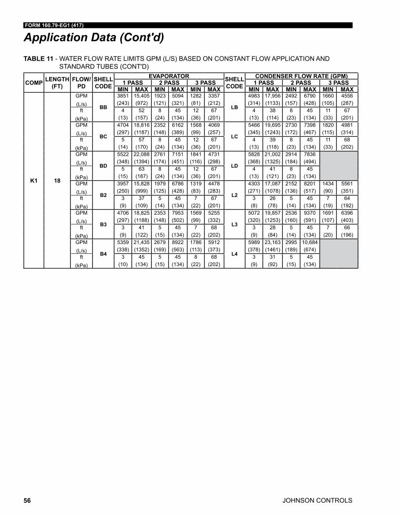
JOHNSON CONTROLS
FORM 160.79-EG1 (417)
56
Application Data (Cont'd)TABLE 11 - WATER FLOW RATE LIMITS GPM (L/S) BASED ON CONSTANT FLOW APPLICATION AND
STANDARD TUBES (CONT'D)
COMP LENGTH (FT)
FLOW/PD
SHELL CODE
EVAPORATOR SHELL CODE
CONDENSER FLOW RATE (GPM)1 PASS 2 PASS 3 PASS 1 PASS 2 PASS 3 PASS
MIN MAX MIN MAX MIN MAX MIN MAX MIN MAX MIN MAX
K1 18
GPM(L/s) BB
3851 15,405 1923 5094 1282 3357
LB
4983 17,956 2492 6790 1660 4556 (243) (972) (121) (321) (81) (212) (314) (1133) (157) (428) (105) (287)
ft(kPa)
4 52 8 45 12 67 4 38 8 45 11 67 (13) (157) (24) (134) (36) (201) (13) (114) (23) (134) (33) (201)
GPM(L/s) BC
4704 18,816 2352 6162 1568 4069
LC
5466 19,695 2730 7398 1820 4981 (297) (1187) (148) (389) (99) (257) (345) (1243) (172) (467) (115) (314)
ft(kPa)
5 57 8 45 12 67 4 39 8 45 11 68 (14) (170) (24) (134) (36) (201) (13) (118) (23) (134) (33) (202)
GPM(L/s) BD
5522 22,088 2761 7151 1841 4731
LD
5828 21,002 2914 7836 (348) (1394) (174) (451) (116) (298) (368) (1325) (184) (494)
ft(kPa)
5 63 8 45 12 67 4 41 8 45 (15) (187) (24) (134) (36) (201) (13) (121) (23) (134)
GPM(L/s) B2
3957 15,828 1979 6786 1319 4478
L2
4303 17,087 2152 8201 1434 5561 (250) (999) (125) (428) (83) (283) (271) (1078) (136) (517) (90) (351)
ft(kPa)
3 37 5 45 7 67 3 26 5 45 7 64 (9) (109) (14) (134) (22) (201) (8) (78) (14) (134) (19) (192)
GPM(L/s) B3
4706 18,825 2353 7953 1569 5255
L3
5072 19,857 2536 9370 1691 6396 (297) (1188) (148) (502) (99) (332) (320) (1253) (160) (591) (107) (403)
ft(kPa)
3 41 5 45 7 68 3 28 5 45 7 66 (9) (122) (15) (134) (22) (202) (9) (84) (14) (134) (20) (196)
GPM(L/s) B4
5359 21,435 2679 8922 1786 5912
L4
5989 23,163 2995 10,684 (338) (1352) (169) (563) (113) (373) (378) (1461) (189) (674)
ft(kPa)
3 45 5 45 8 68 3 31 5 45 (10) (134) (15) (134) (22) (202) (9) (92) (15) (134)
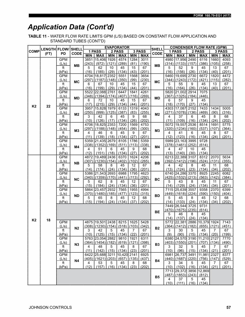
FORM 160.79-EG1 (417)
JOHNSON CONTROLS 57
Application Data (Cont'd)TABLE 11 - WATER FLOW RATE LIMITS GPM (L/S) BASED ON CONSTANT FLOW APPLICATION AND
STANDARD TUBES (CONT'D)
COMP LENGTH (FT)
FLOW/PD
SHELL CODE
EVAPORATOR SHELL CODE
CONDENSER FLOW RATE (GPM)1 PASS 2 PASS 3 PASS 1 PASS 2 PASS 3 PASS
MIN MAX MIN MAX MIN MAX MIN MAX MIN MAX MIN MAX
K2 22
GPM
MB3851 15,406 1926 4574 1284 3011
MB4980 17,956 2490 6116 1660 4093
(L/s) (243) (972) (121) (289) (81) (190) (314) (1133) (157) (386) (105) (258)ft 5 62 10 45 15 67 5 52 9 45 13 67
(kPa) (16) (185) (29) (134) (43) (201) (16) (156) (26) (134) (40) (201)GPM
MC4704 18,817 2352 5551 1568 3654
MC5460 19,695 2730 6672 1820 4472
(L/s) (297) (1187) (148) (350) (99) (230) (344) (1243) (172) (421) (115) (282)ft 6 67 10 45 15 67 5 55 9 45 13 67
(kPa) (16) (199) (29) (134) (44) (201) (16) (164) (26) (134) (40) (201)GPM
MD5522 22,088 2761 6447 1841 4261
MD5820 21,002 2914 7075
(L/s) (348) (1394) (174) (407) (116) (269) (367) (1325) (184) (446)ft 6 72 10 45 15 67 6 57 9 45
(kPa) (17) (215) (29) (134) (44) (201) (18) (170) (27) (134)GPM
M23957 15,828 1979 6133 1319 4043
M24303 17,087 2152 7433 1434 5005
(L/s) (250) (999) (125) (387) (83) (255) (271) (1078) (136) (469) (90) (316)ft 3 42 6 45 9 68 4 37 6 45 8 68
(kPa) (10) (126) (17) (134) (26) (202) (11) (109) (16) (134) (24) (202)GPM
M34706 18,825 2353 7200 1569 4753
M35072 19,557 2536 8514 1691 5775
(L/s) (297) (1188) (148) (454) (99) (300) (320) (1234) (160) (537) (107) (364)ft 4 46 6 45 9 67 4 41 6 45 8 67
(kPa) (11) (139) (18) (134) (27) (201) (12) (123) (16) (134) (24) (201)GPM
M45359 21,435 2679 8105 1786 5359
M45989 23,163 3995 9728
(L/s) (338) (1352) (169) (511) (113) (338) (378) (1461) (252) (614)ft 4 51 6 45 9 68 4 47 10 45
(kPa) (12) (151) (18) (134) (27) (202) (13) (140) (30) (134)
K2 18
GPM
NB4872 19,489 2436 6370 1624 4206
BB6213 22,389 3107 8312 2070 5634
(L/s) (307) (1230) (154) (402) (102) (265) (392) (1412) (196) (524) (131) (355)ft 5 58 8 45 12 67 4 42 8 45 11 68
(kPa) (14) (174) (24) (134) (36) (201) (13) (124) (23) (134) (34) (202)GPM
NC5386 21,543 2693 6988 1795 4623
BC6740 24,286 3370 8925 2245 6082
(L/s) (340) (1359) (170) (441) (113) (292) (425) (1532) (213) (563) (142) (384)ft 5 62 8 45 12 67 5 43 8 45 11 67
(kPa) (15) (184) (24) (134) (36) (201) (14) (129) (24) (134) (34) (201)GPM
ND5864 23,457 2932 7565 1955 4994
BD7115 25,639 3557 9358 2370 6399
(L/s) (370) (1480) (185) (477) (123) (315) (449) (1618) (224) (590) (150) (404)ft 5 65 8 45 12 68 5 45 8 45 12 68
(kPa) (15) (194) (24) (134) (37) (202) (14) (133) (24) (134) (34) (202)
BE7449 26,544 3725 9731 (470) (1675) (235) (614)
5 46 8 45 (14) (137) (24) (134)
GPM
N24875 19,501 2438 8215 1625 5428
B25772 22,381 2886 10,379 1924 7143
(L/s) (308) (1230) (154) (518) (103) (342) (364) (1412) (182) (655) (121) (451)ft 3 42 5 45 7 67 3 30 5 45 7 67
(kPa) (10) (125) (15) (134) (22) (201) (9) (90) (15) (134) (20) (199)GPM
N35763 23,054 2882 9810 1921 6311
B36380 24,570 3190 11,210 2127 7770
(L/s) (364) (1454) (182) (619) (121) (398) (403) (1550) (201) (707) (134) (490)ft 4 48 5 45 8 67 3 32 5 45 7 67
(kPa) (11) (142) (15) (134) (23) (201) (10) (96) (15) (134) (21) (201)GPM
N46422 25,688 3211 10,420 2141 6925
B46981 26,737 3491 11,981 2327 8377
(L/s) (405) (1621) (203) (657) (135) (437) (440) (1687) (220) (756) (147) (529)ft 4 53 5 45 8 68 3 34 5 45 7 67
(kPa) (12) (157) (16) (134) (23) (202) (10) (102) (16) (134) (21) (201)
B57713 29,372 3856 12,869 (487) (1853) (243) (812)
4 37 5 45 (10) (111) (16) (134)
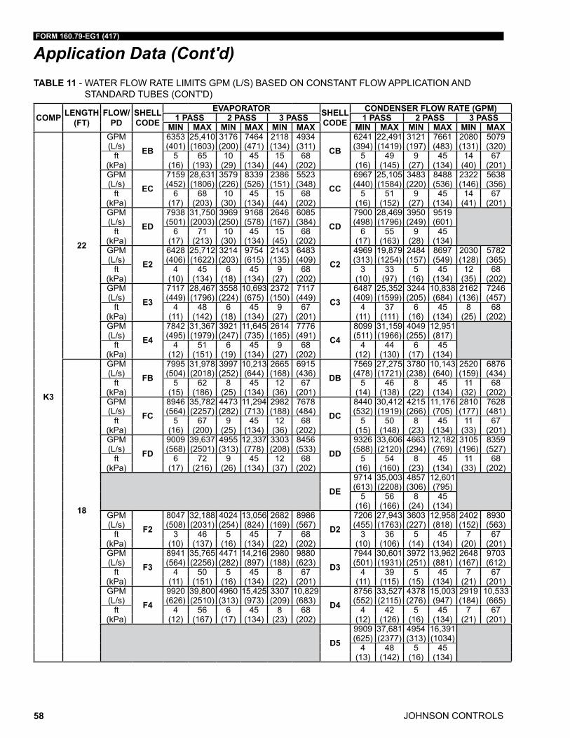
JOHNSON CONTROLS
FORM 160.79-EG1 (417)
58
Application Data (Cont'd)TABLE 11 - WATER FLOW RATE LIMITS GPM (L/S) BASED ON CONSTANT FLOW APPLICATION AND
STANDARD TUBES (CONT'D)
COMP LENGTH (FT)
FLOW/PD
SHELL CODE
EVAPORATOR SHELL CODE
CONDENSER FLOW RATE (GPM)1 PASS 2 PASS 3 PASS 1 PASS 2 PASS 3 PASS
MIN MAX MIN MAX MIN MAX MIN MAX MIN MAX MIN MAX
K3
22
GPM
EB6353 25,410 3176 7464 2118 4934
CB6241 22,491 3121 7661 2080 5079
(L/s) (401) (1603) (200) (471) (134) (311) (394) (1419) (197) (483) (131) (320)ft 5 65 10 45 15 68 5 49 9 45 14 67
(kPa) (16) (193) (29) (134) (44) (202) (16) (145) (27) (134) (40) (201)GPM
EC7159 28,631 3579 8339 2386 5523
CC6967 25,105 3483 8488 2322 5638
(L/s) (452) (1806) (226) (526) (151) (348) (440) (1584) (220) (536) (146) (356)ft 6 68 10 45 15 68 5 51 9 45 14 67
(kPa) (17) (203) (30) (134) (44) (202) (16) (152) (27) (134) (41) (201)GPM
ED7938 31,750 3969 9168 2646 6085
CD7900 28,469 3950 9519
(L/s) (501) (2003) (250) (578) (167) (384) (498) (1796) (249) (601)ft 6 71 10 45 15 68 6 55 9 45
(kPa) (17) (213) (30) (134) (45) (202) (17) (163) (28) (134)GPM
E26428 25,712 3214 9754 2143 6483
C24969 19,879 2484 8697 2030 5782
(L/s) (406) (1622) (203) (615) (135) (409) (313) (1254) (157) (549) (128) (365)ft 4 45 6 45 9 68 3 33 5 45 12 68
(kPa) (10) (134) (18) (134) (27) (202) (10) (97) (16) (134) (35) (202)GPM
E37117 28,467 3558 10,693 2372 7117
C36487 25,352 3244 10,838 2162 7246
(L/s) (449) (1796) (224) (675) (150) (449) (409) (1599) (205) (684) (136) (457)ft 4 48 6 45 9 67 4 37 6 45 8 68
(kPa) (11) (142) (18) (134) (27) (201) (11) (111) (16) (134) (25) (202)GPM
E47842 31,367 3921 11,645 2614 7776
C48099 31,159 4049 12,951
(L/s) (495) (1979) (247) (735) (165) (491) (511) (1966) (255) (817)ft 4 51 6 45 9 68 4 44 6 45
(kPa) (12) (151) (19) (134) (27) (202) (12) (130) (17) (134)
18
GPM
FB7995 31,978 3997 10,213 2665 6915
DB7569 27,275 3780 10,143 2520 6876
(L/s) (504) (2018) (252) (644) (168) (436) (478) (1721) (238) (640) (159) (434)ft 5 62 8 45 12 67 5 46 8 45 11 68
(kPa) (15) (186) (25) (134) (36) (201) (14) (138) (22) (134) (32) (202)GPM
FC8946 35,782 4473 11,294 2982 7678
DC8440 30,412 4215 11,176 2810 7628
(L/s) (564) (2257) (282) (713) (188) (484) (532) (1919) (266) (705) (177) (481)ft 5 67 9 45 12 68 5 50 8 45 11 67
(kPa) (16) (200) (25) (134) (36) (202) (15) (148) (23) (134) (33) (201)GPM
FD9009 39,637 4955 12,337 3303 8456
DD9326 33,606 4663 12,182 3105 8359
(L/s) (568) (2501) (313) (778) (208) (533) (588) (2120) (294) (769) (196) (527)ft 6 72 9 45 12 68 5 54 8 45 11 68
(kPa) (17) (216) (26) (134) (37) (202) (16) (160) (23) (134) (33) (202)
DE9714 35,003 4857 12,601 (613) (2208) (306) (795)
5 56 8 45 (16) (166) (24) (134)
GPM
F28047 32,188 4024 13,056 2682 8986
D27206 27,943 3603 12,958 2402 8930
(L/s) (508) (2031) (254) (824) (169) (567) (455) (1763) (227) (818) (152) (563)ft 3 46 5 45 7 68 3 36 5 45 7 67
(kPa) (10) (137) (16) (134) (22) (202) (10) (106) (14) (134) (20) (201)GPM
F38941 35,765 4471 14,216 2980 9880
D37944 30,601 3972 13,962 2648 9703
(L/s) (564) (2256) (282) (897) (188) (623) (501) (1931) (251) (881) (167) (612)ft 4 50 5 45 8 67 4 39 5 45 7 67
(kPa) (11) (151) (16) (134) (22) (201) (11) (115) (15) (134) (21) (201)GPM
F49920 39,800 4960 15,425 3307 10,829
D48756 33,527 4378 15,003 2919 10,533
(L/s) (626) (2510) (313) (973) (209) (683) (552) (2115) (276) (947) (184) (665)ft 4 56 6 45 8 68 4 42 5 45 7 67
(kPa) (12) (167) (17) (134) (23) (202) (12) (126) (16) (134) (21) (201)
D59909 37,681 4954 16,391 (625) (2377) (313) (1034)
4 48 5 45 (13) (142) (16) (134)
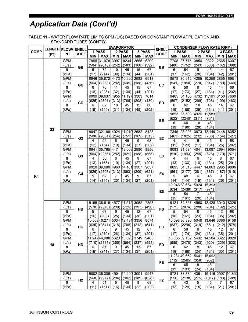
FORM 160.79-EG1 (417)
JOHNSON CONTROLS 59
Application Data (Cont'd)
COMPLENGTH
(FT)FLOW/
PDSHELL CODE
EVAPORATOR SHELL CODE
CONDENSER FLOW RATE (GPM)1 PASS 2 PASS 3 PASS 1 PASS 2 PASS 3 PASS
MIN MAX MIN MAX MIN MAX MIN MAX MIN MAX MIN MAX
K4
22
GPM
GB
7995 31,978 3997 9234 2665 6209
EB
7708 27,775 3850 9322 2565 6307 (L/s) (504) (2018) (252) (583) (168) (392) (486) (1752) (243) (588) (162) (398)
ft 6 72 10 45 15 67 6 54 9 45 14 67 (kPa) (17) (214) (30) (134) (44) (201) (17) (162) (28) (134) (42) (201)GPM
GC
8946 35,872 4473 10,220 2982 6918
EC
8578 30,912 4285 10,259 2855 6981 (L/s) (564) (2263) (282) (645) (188) (436) (541) (1950) (270) (647) (180) (440)
ft 6 76 11 45 15 67 6 58 9 45 14 68 (kPa) (18) (228) (32) (134) (44) (201) (17) (173) (27) (134) (41) (202)GPM
GD
9909 39,637 4955 11,197 3303 7614
ED
9465 34,106 4732 11,191 3150 7660 (L/s) (625) (2501) (313) (706) (208) (480) (597) (2152) (299) (706) (199) (483)
ft 6 82 10 45 15 68 6 62 10 45 14 67 (kPa) (19) (244) (31) (134) (45) (202) (19) (185) (29) (134) (41) (201)
EE
9853 35,503 4926 11,583 (622) (2240) (311) (731)
6 64 10 45 (19) (190) (29) (134)
GPM
G2
8047 32,188 4024 11,910 2682 8128
E2
7345 28,926 3673 12,149 2448 8352 (L/s) (508) (2031) (254) (751) (169) (513) (463) (1825) (232) (766) (154) (527)
ft 4 52 6 45 9 68 4 41 6 45 8 68 (kPa) (12) (154) (19) (134) (27) (202) (11) (123) (17) (134) (25) (202)GPM
G3
8941 35,765 4471 13,009 2980 8956
E3
8083 31,584 4041 13,087 2694 9054 (L/s) (564) (2256) (282) (821) (188) (565) (510) (1993) (255) (826) (170) (571)
ft 4 56 6 45 9 67 4 44 6 45 8 67 (kPa) (13) (168) (19) (134) (27) (201) (13) (133) (18) (134) (25) (201)GPM
G4
9920 39,680 4960 14,161 3307 9837
E4
8895 34,510 4447 14,063 2965 9806 (L/s) (626) (2503) (313) (893) (209) (621) (561) (2177) (281) (887) (187) (619)
ft 5 62 7 45 9 67 5 48 6 45 9 67 (kPa) (14) (184) (20) (134) (27) (201) (14) (144) (19) (134) (26) (201)
E5
10,048 38,664 5024 15,393 (634) (2439) (317) (971)
5 54 7 45 (15) (161) (20) (134)
18
GPM
HB
9155 36,619 4577 11,512 3052 7858
FB
9121 32,867 4560 12,428 3040 8326 (L/s) (578) (2310) (289) (726) (193) (496) (575) (2074) (288) (784) (192) (525)
ft 5 68 9 45 12 67 5 54 8 45 12 68 (kPa) (16) (203) (25) (134) (36) (201) (16) (161) (23) (134) (35) (202)GPM
HC
10,068 40,271 5034 12,484 3356 8574
FC
10,098 36,390 5049 13,646 3366 9158 (L/s) (635) (2541) (318) (788) (212) (541) (637) (2296) (319) (861) (212) (578)
ft 6 73 9 45 12 67 6 58 8 45 12 67 (kPa) (17) (219) (26) (134) (37) (201) (17) (174) (24) (134) (35) (201)GPM
HD
11,247 44,988 5623 13,693 3749 9485
FD
10,865 39,152 5432 14,584 3622 9820 (L/s) (710) (2838) (355) (864) (237) (598) (685) (2470) (343) (920) (229) (620)
ft 6 81 9 45 13 67 6 62 8 45 12 67 (kPa) (18) (241) (27) (134) (37) (201) (18) (186) (24) (134) (35) (201)
FE
11,281 40,652 5641 15,092 (712) (2565) (356) (952)
6 65 8 45 (19) (193) (24) (134)
GPM
H2
9002 36,006 4501 14,290 3001 9947
F2
8721 33,884 4361 16,116 2907 10,899 (L/s) (568) (2272) (284) (902) (189) (628) (550) (2138) (275) (1017) (183) (688)
ft 4 51 5 45 8 68 4 43 5 45 7 67 (kPa) (11) (151) (16) (134) (22) (202) (12) (129) (15) (134) (21) (201)
TABLE 11 - WATER FLOW RATE LIMITS GPM (L/S) BASED ON CONSTANT FLOW APPLICATION AND STANDARD TUBES (CONT'D)
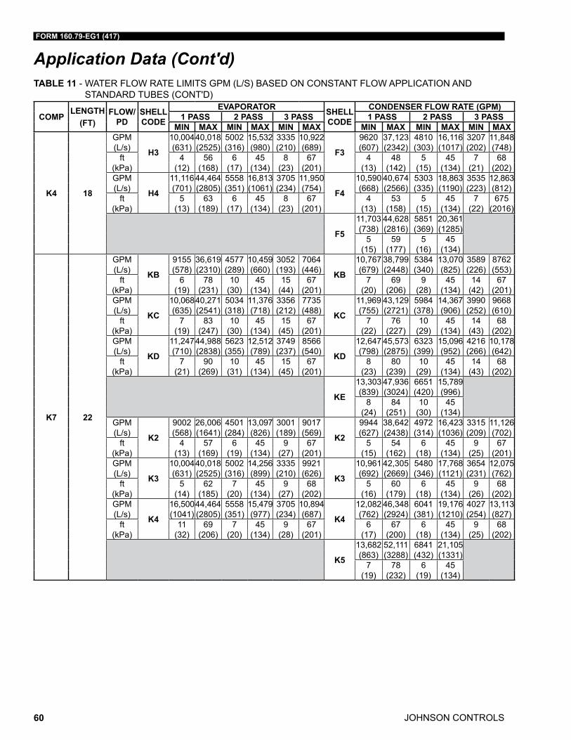
JOHNSON CONTROLS
FORM 160.79-EG1 (417)
60
Application Data (Cont'd)
COMPLENGTH
(FT)FLOW/
PDSHELL CODE
EVAPORATOR SHELL CODE
CONDENSER FLOW RATE (GPM)1 PASS 2 PASS 3 PASS 1 PASS 2 PASS 3 PASS
MIN MAX MIN MAX MIN MAX MIN MAX MIN MAX MIN MAX
K4 18
GPM
H3
10,004 40,018 5002 15,532 3335 10,922
F3
9620 37,123 4810 16,116 3207 11,848 (L/s) (631) (2525) (316) (980) (210) (689) (607) (2342) (303) (1017) (202) (748)
ft 4 56 6 45 8 67 4 48 5 45 7 68 (kPa) (12) (168) (17) (134) (23) (201) (13) (142) (15) (134) (21) (202)GPM
H4
11,116 44,464 5558 16,813 3705 11,950
F4
10,590 40,674 5303 18,863 3535 12,863 (L/s) (701) (2805) (351) (1061) (234) (754) (668) (2566) (335) (1190) (223) (812)
ft 5 63 6 45 8 67 4 53 5 45 7 675 (kPa) (13) (189) (17) (134) (23) (201) (13) (158) (15) (134) (22) (2016)
F5
11,703 44,628 5851 20,361 (738) (2816) (369) (1285)
5 59 5 45 (15) (177) (16) (134)
K7 22
GPM
KB
9155 36,619 4577 10,459 3052 7064
KB
10,767 38,799 5384 13,070 3589 8762 (L/s) (578) (2310) (289) (660) (193) (446) (679) (2448) (340) (825) (226) (553)
ft 6 78 10 45 15 67 7 69 9 45 14 67 (kPa) (19) (231) (30) (134) (44) (201) (20) (206) (28) (134) (42) (201)GPM
KC
10,068 40,271 5034 11,376 3356 7735
KC
11,969 43,129 5984 14,367 3990 9668 (L/s) (635) (2541) (318) (718) (212) (488) (755) (2721) (378) (906) (252) (610)
ft 7 83 10 45 15 67 7 76 10 45 14 68 (kPa) (19) (247) (30) (134) (45) (201) (22) (227) (29) (134) (43) (202)GPM
KD
11,247 44,988 5623 12,512 3749 8566
KD
12,647 45,573 6323 15,096 4216 10,178 (L/s) (710) (2838) (355) (789) (237) (540) (798) (2875) (399) (952) (266) (642)
ft 7 90 10 45 15 67 8 80 10 45 14 68 (kPa) (21) (269) (31) (134) (45) (201) (23) (239) (29) (134) (43) (202)
KE
13,303 47,936 6651 15,789 (839) (3024) (420) (996)
8 84 10 45 (24) (251) (30) (134)
GPM
K2
9002 26,006 4501 13,097 3001 9017
K2
9944 38,642 4972 16,423 3315 11,126 (L/s) (568) (1641) (284) (826) (189) (569) (627) (2438) (314) (1036) (209) (702)
ft 4 57 6 45 9 67 5 54 6 45 9 67 (kPa) (13) (169) (19) (134) (27) (201) (15) (162) (18) (134) (25) (201)GPM
K3
10,004 40,018 5002 14,256 3335 9921
K3
10,961 42,305 5480 17,768 3654 12,075 (L/s) (631) (2525) (316) (899) (210) (626) (692) (2669) (346) (1121) (231) (762)
ft 5 62 7 45 9 68 5 60 6 45 9 68 (kPa) (14) (185) (20) (134) (27) (202) (16) (179) (18) (134) (26) (202)GPM
K4
16,500 44,464 5558 15,479 3705 10,894
K4
12,082 46,348 6041 19,176 4027 13,113 (L/s) (1041) (2805) (351) (977) (234) (687) (762) (2924) (381) (1210) (254) (827)
ft 11 69 7 45 9 67 6 67 6 45 9 68 (kPa) (32) (206) (20) (134) (28) (201) (17) (200) (18) (134) (25) (202)
K5
13,682 52,111 6841 21,105 (863) (3288) (432) (1331)
7 78 6 45 (19) (232) (19) (134)
TABLE 11 - WATER FLOW RATE LIMITS GPM (L/S) BASED ON CONSTANT FLOW APPLICATION AND STANDARD TUBES (CONT'D)
FORM 160.79-EG1 (417)
JOHNSON CONTROLS 61
Electrical Considerations
ELECTRICAL CONSIDERATIONS
Motor Voltage – Low voltage motors (380 to 575 volts) are furnished with six leads (or multiples of six leads). Medium voltage (2300 volts and above) motors have three leads. Motor circuit conductor size must be in accord ance with the National Electrical Code (N.E.C.), or other applica ble codes, for the motor full load amperes (FLA). Flexible conduit should be used for the last several feet to the chiller in order to provide vibration isolation. Table 12 on page 62 lists the allowable variation in voltage supplied to the chiller mo-tor. The unit name plate is stamped with the specific motor voltage, and frequency for the appropri ate motor.
Starters – The YD chiller requires two starters, one connected to each of the chiller mo-tors. The two starters may be individually connected to a power source, or the starters may be furnished as a package with the two incoming feeds bussed or cabled together. When used, electro-mechanical starters must be furnished in accord ance with YORK Standard Specifications (R-1206). This will ensure that starter components, controls, cir-cuits, and terminal markings will be suitable for required overall system performance.
Controls and Oil Pump Power Supplies -The YD chiller is provided with an auxiliary variable speed oil pump drive panel. This panel operates the two oil pump motors and the two oil reservoir heaters. This panel houses the control power supply change-over switch to allow the operation of either compressor/motor in the event that the other compres-sor/motor must be totally de-energized and locked out for service. It requires a 3-phase power supply and 115V power source from each of the starters/drives. If a separate power source is required, a Special Quote (SQ) is required.
Chillers with unit mounted starters/drives are supplied with factory wired power connec-tions. Remote mounted starters/drives require these power connections to be installed by the electrical installation contractor
Copper Conductors – Only copper conductors should be connected to compres-sor motors and starters. Aluminum conductors have proven to be un satisfactory when connected to copper lugs. Aluminum oxide and the difference in thermal conductivity be-tween copper and aluminum cannot guarantee the re quired tight connection over a long period of time.
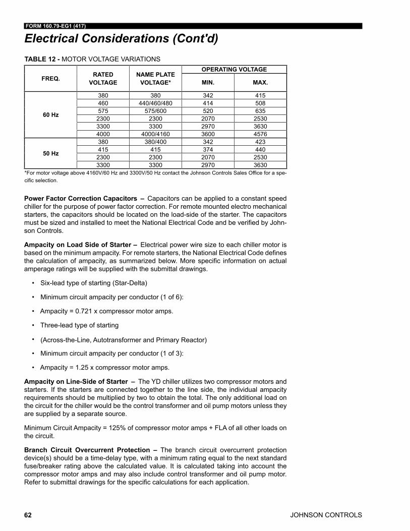
JOHNSON CONTROLS
FORM 160.79-EG1 (417)
62
Electrical Considerations (Cont'd)TABLE 12 - MOTOR VOLTAGE VARIATIONS
FREQ. RATED VOLTAGE
NAME PLATE VOLTAGE*
OPERATING VOLTAGE
MIN. MAX.
60 Hz
380 380 342 415460 440/460/480 414 508575 575/600 520 6352300 2300 2070 25303300 3300 2970 36304000 4000/4160 3600 4576
50 Hz
380 380/400 342 423415 415 374 4402300 2300 2070 25303300 3300 2970 3630
*For motor voltage above 4160V/60 Hz and 3300V/50 Hz contact the Johnson Controls Sales Office for a spe-cific selection.
Power Factor Correction Capacitors – Capacitors can be applied to a constant speed chiller for the purpose of power factor correction. For remote mounted electro mechanical starters, the ca pacitors should be located on the load-side of the starter. The capacitors must be sized and installed to meet the National Electrical Code and be verified by John-son Controls.
Ampacity on Load Side of Starter – Electrical power wire size to each chiller motor is based on the minimum ampacity. For remote starters, the National Electrical Code defines the calculation of ampacity, as summa rized below. More specific information on actual amper age ratings will be supplied with the submittal drawings.
• Six-lead type of starting (Star-Delta)
• Minimum circuit ampacity per conductor (1 of 6):
• Ampacity = 0.721 x compressor motor amps.
• Three-lead type of starting
• (Across-the-Line, Autotransformer and Primary Reactor)
• Minimum circuit ampacity per conductor (1 of 3):
• Ampacity = 1.25 x compressor motor amps.
Ampacity on Line-Side of Starter – The YD chiller utilizes two compressor motors and starters. If the starters are connected together to the line side, the individual ampacity requirements should be multiplied by two to obtain the total. The only additional load on the circuit for the chiller would be the control transformer and oil pump motors unless they are sup plied by a separate source.
Minimum Circuit Ampacity = 125% of compressor motor amps + FLA of all other loads on the circuit.
Branch Circuit Overcurrent Protection – The branch circuit overcurrent protection device(s) should be a time-delay type, with a minimum rating equal to the next standard fuse/breaker rating above the calculated value. It is calculated taking into account the compres sor motor amps and may also include control trans former and oil pump motor. Refer to submittal drawings for the specific calculations for each application.
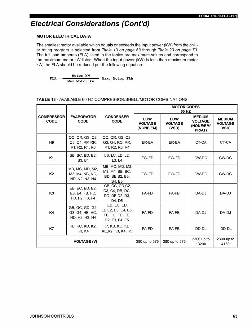
FORM 160.79-EG1 (417)
JOHNSON CONTROLS 63
Electrical Considerations (Cont'd)MOTOR ELECTRICAL DATA
The smallest motor available which equals or exceeds the Input power (kW) from the chill-er rating program is selected from Table 13 on page 63 through Table 23 on page 70. The full load amperes (FLA) listed in the tables are maximum values and correspond to the maximum motor kW listed. When the input power (kW) is less than maximum motor kW, the FLA should be reduced per the following equation:
FLA = Motor kW
Max. Motor FLAMax Motor kw
TABLE 13 - AVAILABLE 60 HZ COMPRESSOR/SHELL/MOTOR COMBINATIONS
COMPRESSOR CODE
EVAPORATOR CODE
CONDENSER CODE
MOTOR CODES60 HZ
LOW VOLTAGE
(NONE/EM)
LOW VOLTAGE
(VSD)
MEDIUM VOLTAGE
(NONE/EM/PR/AT)
MEDIUM VOLTAGE
(VSD)
H9QQ, QR, QS, Q2, Q3, Q4, RP, RR, RT, R2, R4, R6
QQ, QR, QS, Q2, Q3, Q4, RQ, RR, RT, R2, R3, R4
ER-EA ER-EA CT-CA CT-CA
K1 BB, BC, BD, B2, B3, B4
LB, LC, LD, L2, L3, L4
EW-FD EW-FD CW-DC CW-DC
K2MB, MC, MD, M2, M3, M4, NB, NC, ND, N2, N3, N4
MB, MC, MD, M2, M3, M4, BB, BC, BD, BE,B2, B3,
B4, B5
EW-FD EW-FD CW-DC CW-DC
K3EB, EC, ED, E2, E3, E4, FB, FC, FD, F2, F3, F4
CB, CC, CD,C2, C3, C4, DB, DC, DD, DE,D2, D3,
D4, D5
FA-FD FA-FB DA-DJ DA-DJ
K4GB, GC, GD, G2, G3, G4, HB, HC, HD, H2, H3, H4
EB, EC, ED, EE,E2, E3, E4, E5,
FB, FC, FD, FE, F2, F3, F4, F5
FA-FD FA-FB DA-DJ DA-DJ
K7 KB, KC, KD, K2, K3, K4
K7, KB, KC, KD, KE,K2, K3, K4, K5
FA-FD FA-FB DD-DL DD-DL
VOLTAGE (V) 380 up to 575 380 up to 5752300 up to
132002300 up to
4160
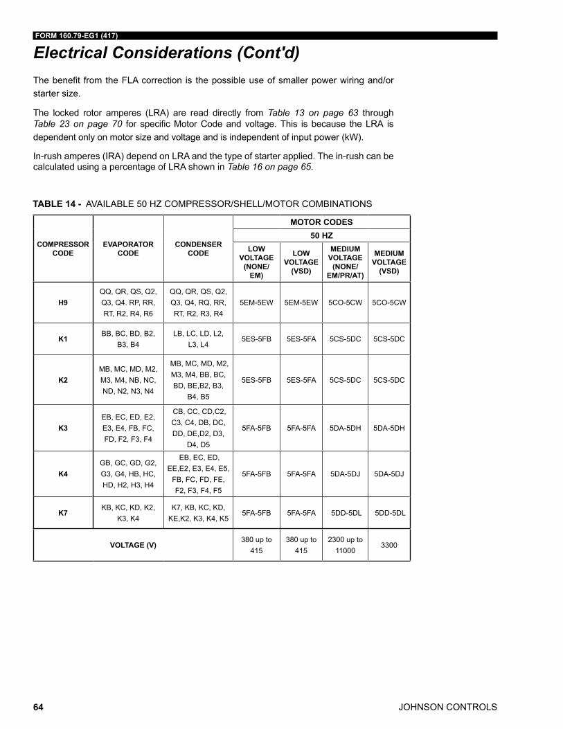
JOHNSON CONTROLS
FORM 160.79-EG1 (417)
64
Electrical Considerations (Cont'd)The benefit from the FLA correction is the possible use of smaller power wiring and/or starter size.
The locked rotor amperes (LRA) are read directly from Table 13 on page 63 through Table 23 on page 70 for specific Motor Code and voltage. This is because the LRA is dependent only on motor size and voltage and is independent of input power (kW).
In-rush amperes (IRA) depend on LRA and the type of starter applied. The in-rush can be calculated using a percentage of LRA shown in Table 16 on page 65.
TABLE 14 - AVAILABLE 50 HZ COMPRESSOR/SHELL/MOTOR COMBINATIONS
COMPRESSOR CODE
EVAPORATOR CODE
CONDENSER CODE
MOTOR CODES50 HZ
LOW VOLTAGE
(NONE/EM)
LOW VOLTAGE
(VSD)
MEDIUM VOLTAGE
(NONE/EM/PR/AT)
MEDIUM VOLTAGE
(VSD)
H9QQ, QR, QS, Q2, Q3, Q4. RP, RR, RT, R2, R4, R6
QQ, QR, QS, Q2, Q3, Q4, RQ, RR, RT, R2, R3, R4
5EM-5EW 5EM-5EW 5CO-5CW 5CO-5CW
K1BB, BC, BD, B2,
B3, B4LB, LC, LD, L2,
L3, L4 5ES-5FB 5ES-5FA 5CS-5DC 5CS-5DC
K2MB, MC, MD, M2, M3, M4, NB, NC, ND, N2, N3, N4
MB, MC, MD, M2, M3, M4, BB, BC, BD, BE,B2, B3,
B4, B5
5ES-5FB 5ES-5FA 5CS-5DC 5CS-5DC
K3EB, EC, ED, E2, E3, E4, FB, FC, FD, F2, F3, F4
CB, CC, CD,C2, C3, C4, DB, DC, DD, DE,D2, D3,
D4, D5
5FA-5FB 5FA-5FA 5DA-5DH 5DA-5DH
K4GB, GC, GD, G2, G3, G4, HB, HC, HD, H2, H3, H4
EB, EC, ED, EE,E2, E3, E4, E5,
FB, FC, FD, FE, F2, F3, F4, F5
5FA-5FB 5FA-5FA 5DA-5DJ 5DA-5DJ
K7KB, KC, KD, K2,
K3, K4K7, KB, KC, KD,
KE,K2, K3, K4, K55FA-5FB 5FA-5FA 5DD-5DL 5DD-5DL
VOLTAGE (V)380 up to
415380 up to
4152300 up to
110003300
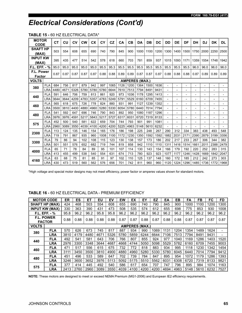
FORM 160.79-EG1 (417)
JOHNSON CONTROLS 65
Electrical Considerations (Cont'd)TABLE 15 - 60 HZ ELECTRICAL DATA*
MOTOR CODE CT CU CV CW CX CY CZ CA CB DA DB DC DD DE DF DH DJ DK DL
SHAFT HP (MAX)
503 554 608 655 690 740 790 845 900 1000 1100 1200 1300 1400 1500 1750 2000 2250 2500
INPUT KW (MAX)
395 435 477 514 542 578 618 660 703 781 859 937 1015 1093 1171 1359 1554 1748 1942
F.L. EFF. - % 95.0 95.0 95.0 95.0 95.0 95.5 95.3 95.5 95.5 95.5 95.5 95.5 95.5 95.5 95.5 96.0 96.0 96.0 96.0F.L. Power
Factor0.87 0.87 0.87 0.87 0.87 0.88 0.88 0.89 0.89 0.87 0.87 0.87 0.88 0.88 0.88 0.87 0.89 0.89 0.89
VOLTS AMPERES (MAX.)
380 FLA 684 756 817 879 942 997 1065 1126 1200 1364 1500 1636 - - - - - - -LRA 4480 4671 5326 5780 5780 5780 6644 7610 7513 7794 8491 9431 - - - - - - -
440 FLA 591 646 706 759 813 861 920 973 1036 1178 1295 1413 - - - - - - -LRA 3644 3644 4209 4783 5357 4783 5249 5791 5529 6160 6709 7455 - - - - - - -
460 FLA 565 618 675 726 778 824 880 931 991 1127 1239 1352 - - - - - - -LRA 3500 3810 4400 4880 4960 5280 5330 6054 5780 6440 7014 7794 - - - - - - -
480 FLA 541 592 647 696 746 790 843 892 950 1080 1187 1296 - - - - - - -LRA 3976 3976 4591 5217 5843 5217 5727 6317 6031 6720 7319 8133 - - - - - - -
575 FLA 452 500 540 581 622 659 704 744 793 901 991 1081 - - - - - - -LRA 2960 3089 3550 4039 4100 4200 4200 5225 4963 5148 5610 6232 - - - - - - -
2300 FLA 113 124 135 146 154 165 176 186 198 225 248 267 290 312 334 383 438 493 548LRA 719 791 867 935 960 1008 1100 1172 1230 1350 1592 1592 1882 2031 2171 2390 2879 3199 3356
3300 FLA 79 86 94 102 108 115 123 130 138 157 173 186 202 217 233 267 306 344 382LRA 501 551 576 652 682 719 744 819 858 942 1110 1110 1311 1416 1514 1661 2011 2388 2479
4000 FLA 65 71 78 84 89 95 101 107 114 130 143 154 166 179 192 220 252 283 315LRA 413 455 499 538 540 554 631 674 713 780 923 923 1077 1177 1246 1428 1669 1842 2047
4160 FLA 63 68 75 81 85 91 97 102 110 125 137 148 160 172 185 212 242 273 303LRA 430 473 519 560 562 576 656 701 742 811 960 960 1120 1224 1296 1485 1736 1772 1968
*Highvoltageandspecialmotordesignsmaynotmeetefficiency,powerfactororamperesvaluesshownforstandardmotors.
TABLE 16 - 60 HZ ELECTRICAL DATA - PREMIUM EFFICIENCY
MOTOR CODE ER ES ET EU EV EW EX EY EZ EA EB FA FB FC FDSHAFT HP (MAX) 424 468 503 554 608 655 690 740 790 845 900 1000 1100 1200 1300INPUT KW (MAX) 330 363 390 431 473 508 535 574 612 655 698 775 853 930 1008
F.L. EFF. - % 95.8 96.2 96.2 95.8 95.8 96.2 96.2 96.2 96.2 96.2 96.2 96.2 96.2 96.2 96.2F.L. POWER
FACTOR 0.88 0.88 0.88 0.88 0.88 0.87 0.87 0.88 0.87 0.88 0.88 0.87 0.87 0.87 0.87
VOLTS AMPERES (MAX.)
380 FLA 570 626 673 745 817 887 934 990 1069 1131 1204 1354 1489 1624 -LRA 3810 4179 4480 4671 5326 5780 5859 6244 6644 7106 7513 7794 8491 9431 -
440 FLA 492 541 581 643 706 766 807 855 924 977 1040 1169 1286 1403 1520LRA 2976 3300 3348 3644 4687 4668 4744 5050 5098 5529 5782 6160 6709 7455 9003
460 FLA 471 517 556 615 675 732 772 818 883 934 995 1118 1230 1342 1454LRA 3111 3450 3500 3810 4900 4880 4960 5280 5330 5780 6045 6440 7014 7794 9412
480 FLA 451 496 533 589 647 702 739 784 847 895 954 1072 1179 1286 1393LRA 3246 3600 3652 3976 5113 5092 5175 5510 5562 6031 6308 6720 7319 8133 9821
575 FLA 377 414 445 492 540 586 617 654 707 747 796 895 984 1074 1163LRA 2413 2760 2960 3089 3550 4039 4100 4200 4200 4694 4963 5148 5610 6232 7527
NOTE:ThesemotorsaredesignedtomeetorexceedNEMAPremium(MG1-2006)andEuropeanIE2efficiencyrequirements.
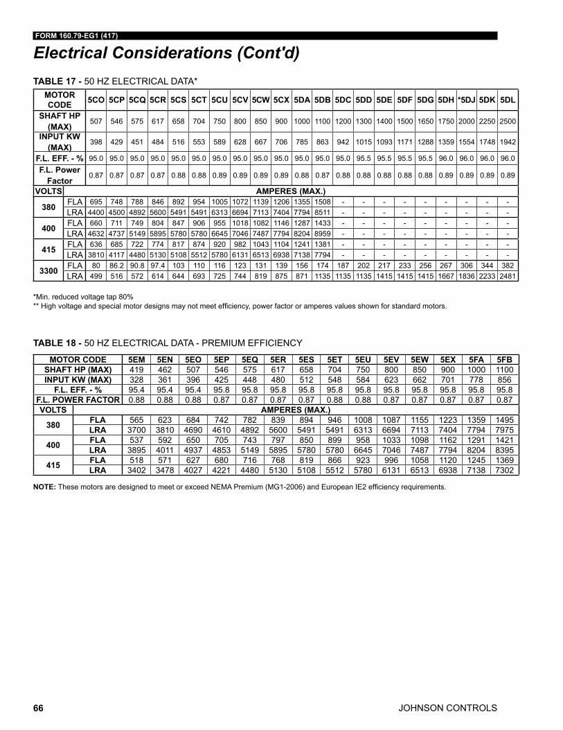
JOHNSON CONTROLS
FORM 160.79-EG1 (417)
66
Electrical Considerations (Cont'd)TABLE 17 - 50 HZ ELECTRICAL DATA*
MOTOR CODE 5CO 5CP 5CQ 5CR 5CS 5CT 5CU 5CV 5CW 5CX 5DA 5DB 5DC 5DD 5DE 5DF 5DG 5DH *5DJ 5DK 5DL
SHAFT HP (MAX)
507 546 575 617 658 704 750 800 850 900 1000 1100 1200 1300 1400 1500 1650 1750 2000 2250 2500
INPUT KW (MAX)
398 429 451 484 516 553 589 628 667 706 785 863 942 1015 1093 1171 1288 1359 1554 1748 1942
F.L. EFF. - % 95.0 95.0 95.0 95.0 95.0 95.0 95.0 95.0 95.0 95.0 95.0 95.0 95.0 95.5 95.5 95.5 95.5 96.0 96.0 96.0 96.0F.L. Power
Factor0.87 0.87 0.87 0.87 0.88 0.88 0.89 0.89 0.89 0.89 0.88 0.87 0.88 0.88 0.88 0.88 0.88 0.89 0.89 0.89 0.89
VOLTS AMPERES (MAX.)
380 FLA 695 748 788 846 892 954 1005 1072 1139 1206 1355 1508 - - - - - - - - -LRA 4400 4500 4892 5600 5491 5491 6313 6694 7113 7404 7794 8511 - - - - - - - - -
400 FLA 660 711 749 804 847 906 955 1018 1082 1146 1287 1433 - - - - - - - - -LRA 4632 4737 5149 5895 5780 5780 6645 7046 7487 7794 8204 8959 - - - - - - - - -
415 FLA 636 685 722 774 817 874 920 982 1043 1104 1241 1381 - - - - - - - - -LRA 3810 4117 4480 5130 5108 5512 5780 6131 6513 6938 7138 7794 - - - - - - - - -
3300 FLA 80 86.2 90.8 97.4 103 110 116 123 131 139 156 174 187 202 217 233 256 267 306 344 382LRA 499 516 572 614 644 693 725 744 819 875 871 1135 1135 1135 1415 1415 1415 1667 1836 2233 2481
*Min. reduced voltage tap 80% **Highvoltageandspecialmotordesignsmaynotmeetefficiency,powerfactororamperesvaluesshownforstandardmotors.
TABLE 18 - 50 HZ ELECTRICAL DATA - PREMIUM EFFICIENCY
MOTOR CODE 5EM 5EN 5EO 5EP 5EQ 5ER 5ES 5ET 5EU 5EV 5EW 5EX 5FA 5FBSHAFT HP (MAX) 419 462 507 546 575 617 658 704 750 800 850 900 1000 1100INPUT KW (MAX) 328 361 396 425 448 480 512 548 584 623 662 701 778 856
F.L. EFF. - % 95.4 95.4 95.4 95.8 95.8 95.8 95.8 95.8 95.8 95.8 95.8 95.8 95.8 95.8F.L. POWER FACTOR 0.88 0.88 0.88 0.87 0.87 0.87 0.87 0.88 0.88 0.87 0.87 0.87 0.87 0.87VOLTS AMPERES (MAX.)
380 FLA 565 623 684 742 782 839 894 946 1008 1087 1155 1223 1359 1495LRA 3700 3810 4690 4610 4892 5600 5491 5491 6313 6694 7113 7404 7794 7975
400 FLA 537 592 650 705 743 797 850 899 958 1033 1098 1162 1291 1421LRA 3895 4011 4937 4853 5149 5895 5780 5780 6645 7046 7487 7794 8204 8395
415 FLA 518 571 627 680 716 768 819 866 923 996 1058 1120 1245 1369LRA 3402 3478 4027 4221 4480 5130 5108 5512 5780 6131 6513 6938 7138 7302
NOTE:ThesemotorsaredesignedtomeetorexceedNEMAPremium(MG1-2006)andEuropeanIE2efficiencyrequirements.
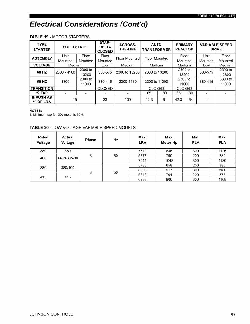
FORM 160.79-EG1 (417)
JOHNSON CONTROLS 67
Electrical Considerations (Cont'd)TABLE 19 - MOTOR STARTERS
TYPESTARTER
SOLID STATESTAR-DELTA
CLOSED
ACROSS-THE-LINE
AUTO TRANSFORMER
PRIMARY REACTOR
VARIABLE SPEED DRIVE
ASSEMBLY Unit Mounted
Floor Mounted
Floor Mounted
Floor Mounted Floor MountedFloor
MountedUnit
MountedFloor
MountedVOLTAGE Medium Low Medium Medium Medium Low Medium
60 HZ 2300 - 41602300 to 13200
380-575 2300 to 13200 2300 to 132002300 to 13200
380-5752300 to 13800
50 HZ 33002300 to 11000
380-415 2300-4160 2300 to 110002300 to 11000
380-4153300 to 11000
TRANSITION - - CLOSED - CLOSED CLOSED - -% TAP - - - - 65 80 65 80 - -
INRUSH AS % OF LRA 45 33 100 42.3 64 42.3 64 - -
NOTES: 1. Minimum tap for 5DJ motor is 80%.
TABLE 20 - LOW VOLTAGE VARIABLE SPEED MODELS
Rated Voltage
Actual Voltage
Phase HzMax.LRA
Max.Motor Hp
Min.FLA
Max.FLA
380 3803 60
7610 845 300 1126
460 440/460/480 5777 790 200 8807014 1048 300 1180
380 380/4003 50
5780 658 200 8808205 917 300 1180
415 415 5512 704 200 8766938 900 300 1108
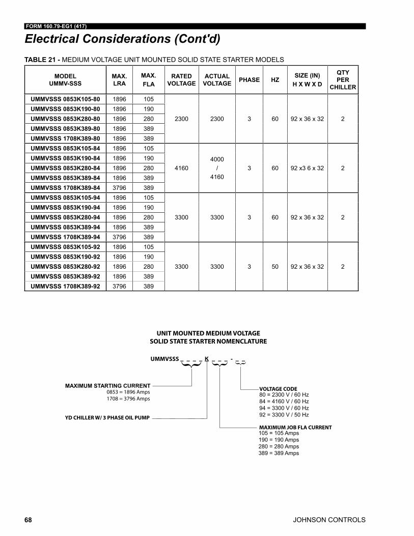
JOHNSON CONTROLS
FORM 160.79-EG1 (417)
68
Electrical Considerations (Cont'd)TABLE 21 - MEDIUM VOLTAGE UNIT MOUNTED SOLID STATE STARTER MODELS
MODEL UMMV-SSS
MAX. LRA
MAX. FLA
RATED VOLTAGE
ACTUAL VOLTAGE PHASE HZ
SIZE (IN)H X W X D
QTY PER
CHILLER
UMMVSSS 0853K105-80 1896 105
2300 2300 3 60 92 x 36 x 32 2UMMVSSS 0853K190-80 1896 190UMMVSSS 0853K280-80 1896 280UMMVSSS 0853K389-80 1896 389UMMVSSS 1708K389-80 1896 389UMMVSSS 0853K105-84 1896 105
41604000
/4160
3 60 92 x3 6 x 32 2UMMVSSS 0853K190-84 1896 190UMMVSSS 0853K280-84 1896 280UMMVSSS 0853K389-84 1896 389UMMVSSS 1708K389-84 3796 389UMMVSSS 0853K105-94 1896 105
3300 3300 3 60 92 x 36 x 32 2UMMVSSS 0853K190-94 1896 190UMMVSSS 0853K280-94 1896 280UMMVSSS 0853K389-94 1896 389UMMVSSS 1708K389-94 3796 389UMMVSSS 0853K105-92 1896 105
3300 3300 3 50 92 x 36 x 32 2UMMVSSS 0853K190-92 1896 190UMMVSSS 0853K280-92 1896 280UMMVSSS 0853K389-92 1896 389UMMVSSS 1708K389-92 3796 389
{ {
UNIT MOUNTED MEDIUM VOLTAGESOLID STATE STARTER NOMENCLATURE
UMMVSSS
0853 = 1896 Amps1708 = 3796 Amps
80 = 2300 V / 60 Hz84 = 4160 V / 60 Hz94 = 3300 V / 60 Hz92 = 3300 V / 50 Hz
MAXIMUM JOB FLA CURRENT
YD CHILLER W/ 3 PHASE OIL PUMP
105 = 105 Amps190 = 190 Amps280 = 280 Amps389 = 389 Amps
VOLTAGE CODE
{
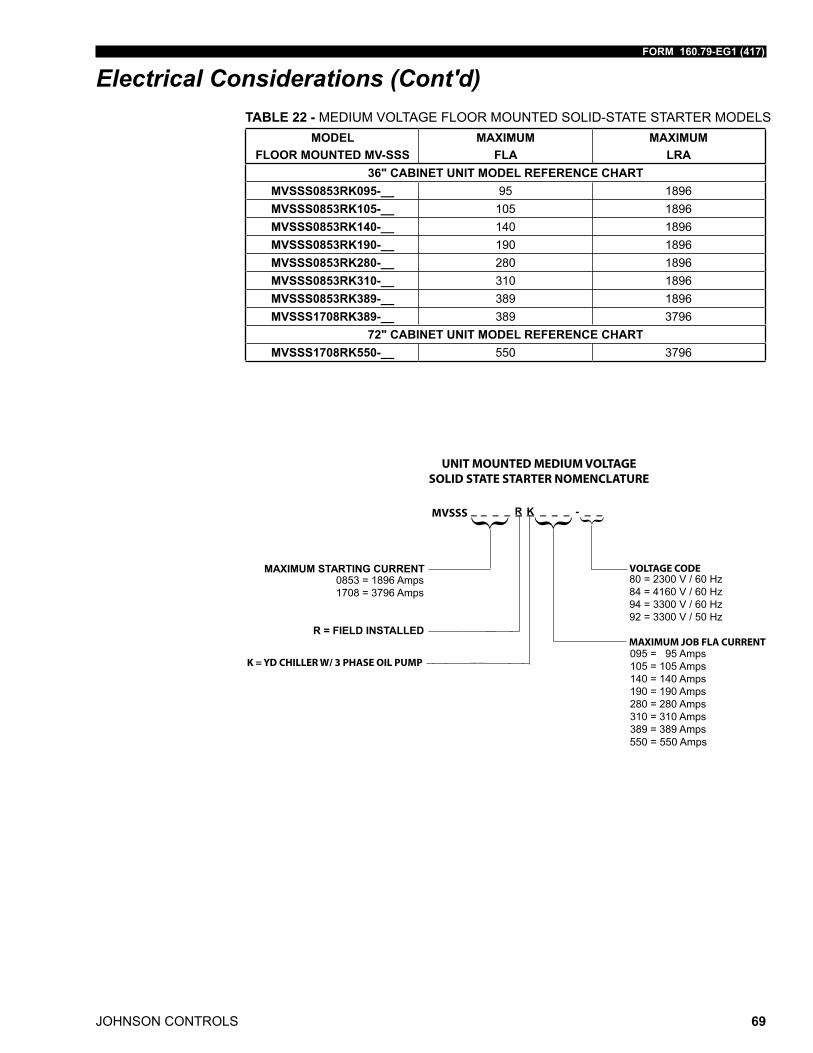
FORM 160.79-EG1 (417)
JOHNSON CONTROLS 69
Electrical Considerations (Cont'd)TABLE 22 - MEDIUM VOLTAGE FLOOR MOUNTED SOLID-STATE STARTER MODELS
MODEL FLOOR MOUNTED MV-SSS
MAXIMUMFLA
MAXIMUMLRA
36" CABINET UNIT MODEL REFERENCE CHARTMVSSS0853RK095-__ 95 1896MVSSS0853RK105-__ 105 1896MVSSS0853RK140-__ 140 1896MVSSS0853RK190-__ 190 1896MVSSS0853RK280-__ 280 1896MVSSS0853RK310-__ 310 1896MVSSS0853RK389-__ 389 1896MVSSS1708RK389-__ 389 3796
72" CABINET UNIT MODEL REFERENCE CHARTMVSSS1708RK550-__ 550 3796
{ {
UNIT MOUNTED MEDIUM VOLTAGESOLID STATE STARTER NOMENCLATURE
MVSSS
80 = 2300 V / 60 Hz84 = 4160 V / 60 Hz94 = 3300 V / 60 Hz92 = 3300 V / 50 Hz
MAXIMUM JOB FLA CURRENT
K = YD CHILLER W/ 3 PHASE OIL PUMP095 = 95 Amps105 = 105 Amps140 = 140 Amps190 = 190 Amps280 = 280 Amps310 = 310 Amps389 = 389 Amps
VOLTAGE CODE
{
R = FIELD INSTALLED
0853 = 1896 Amps1708 = 3796 Amps
550 = 550 Amps
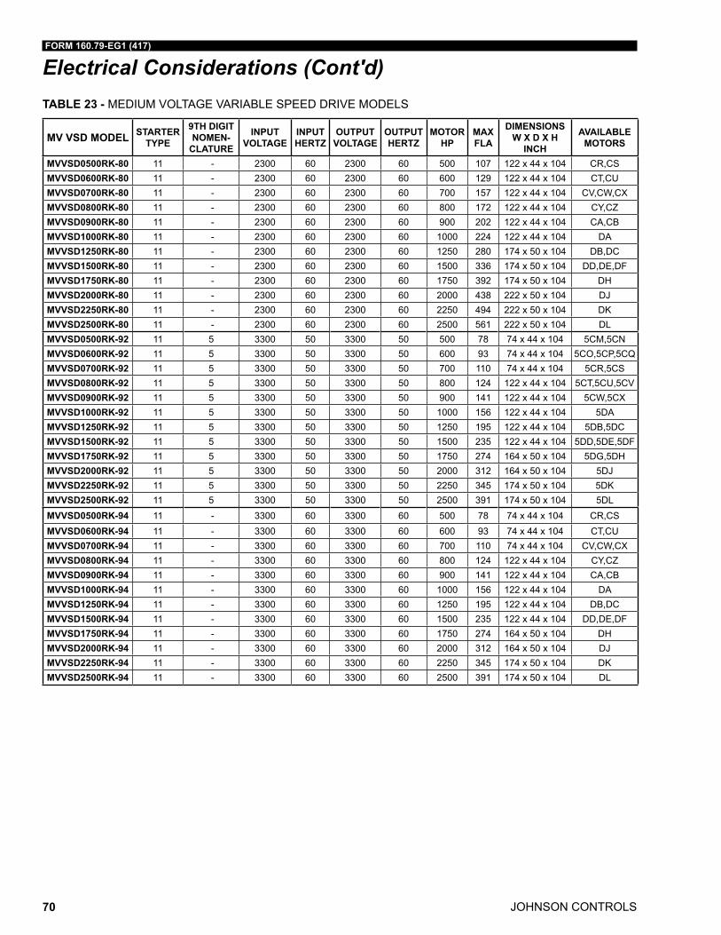
JOHNSON CONTROLS
FORM 160.79-EG1 (417)
70
Electrical Considerations (Cont'd)TABLE 23 - MEDIUM VOLTAGE VARIABLE SPEED DRIVE MODELS
MV VSD MODEL STARTER TYPE
9TH DIGIT NOMEN-
CLATURE
INPUT VOLTAGE
INPUT HERTZ
OUTPUT VOLTAGE
OUTPUT HERTZ
MOTOR HP
MAX FLA
DIMENSIONS W X D X H
INCH
AVAILABLE MOTORS
MVVSD0500RK-80 11 - 2300 60 2300 60 500 107 122 x 44 x 104 CR,CSMVVSD0600RK-80 11 - 2300 60 2300 60 600 129 122 x 44 x 104 CT,CUMVVSD0700RK-80 11 - 2300 60 2300 60 700 157 122 x 44 x 104 CV,CW,CXMVVSD0800RK-80 11 - 2300 60 2300 60 800 172 122 x 44 x 104 CY,CZMVVSD0900RK-80 11 - 2300 60 2300 60 900 202 122 x 44 x 104 CA,CBMVVSD1000RK-80 11 - 2300 60 2300 60 1000 224 122 x 44 x 104 DAMVVSD1250RK-80 11 - 2300 60 2300 60 1250 280 174 x 50 x 104 DB,DCMVVSD1500RK-80 11 - 2300 60 2300 60 1500 336 174 x 50 x 104 DD,DE,DFMVVSD1750RK-80 11 - 2300 60 2300 60 1750 392 174 x 50 x 104 DHMVVSD2000RK-80 11 - 2300 60 2300 60 2000 438 222 x 50 x 104 DJMVVSD2250RK-80 11 - 2300 60 2300 60 2250 494 222 x 50 x 104 DKMVVSD2500RK-80 11 - 2300 60 2300 60 2500 561 222 x 50 x 104 DLMVVSD0500RK-92 11 5 3300 50 3300 50 500 78 74 x 44 x 104 5CM,5CNMVVSD0600RK-92 11 5 3300 50 3300 50 600 93 74 x 44 x 104 5CO,5CP,5CQMVVSD0700RK-92 11 5 3300 50 3300 50 700 110 74 x 44 x 104 5CR,5CSMVVSD0800RK-92 11 5 3300 50 3300 50 800 124 122 x 44 x 104 5CT,5CU,5CVMVVSD0900RK-92 11 5 3300 50 3300 50 900 141 122 x 44 x 104 5CW,5CXMVVSD1000RK-92 11 5 3300 50 3300 50 1000 156 122 x 44 x 104 5DAMVVSD1250RK-92 11 5 3300 50 3300 50 1250 195 122 x 44 x 104 5DB,5DCMVVSD1500RK-92 11 5 3300 50 3300 50 1500 235 122 x 44 x 104 5DD,5DE,5DFMVVSD1750RK-92 11 5 3300 50 3300 50 1750 274 164 x 50 x 104 5DG,5DHMVVSD2000RK-92 11 5 3300 50 3300 50 2000 312 164 x 50 x 104 5DJMVVSD2250RK-92 11 5 3300 50 3300 50 2250 345 174 x 50 x 104 5DKMVVSD2500RK-92 11 5 3300 50 3300 50 2500 391 174 x 50 x 104 5DLMVVSD0500RK-94 11 - 3300 60 3300 60 500 78 74 x 44 x 104 CR,CSMVVSD0600RK-94 11 - 3300 60 3300 60 600 93 74 x 44 x 104 CT,CUMVVSD0700RK-94 11 - 3300 60 3300 60 700 110 74 x 44 x 104 CV,CW,CXMVVSD0800RK-94 11 - 3300 60 3300 60 800 124 122 x 44 x 104 CY,CZMVVSD0900RK-94 11 - 3300 60 3300 60 900 141 122 x 44 x 104 CA,CBMVVSD1000RK-94 11 - 3300 60 3300 60 1000 156 122 x 44 x 104 DAMVVSD1250RK-94 11 - 3300 60 3300 60 1250 195 122 x 44 x 104 DB,DCMVVSD1500RK-94 11 - 3300 60 3300 60 1500 235 122 x 44 x 104 DD,DE,DFMVVSD1750RK-94 11 - 3300 60 3300 60 1750 274 164 x 50 x 104 DHMVVSD2000RK-94 11 - 3300 60 3300 60 2000 312 164 x 50 x 104 DJMVVSD2250RK-94 11 - 3300 60 3300 60 2250 345 174 x 50 x 104 DKMVVSD2500RK-94 11 - 3300 60 3300 60 2500 391 174 x 50 x 104 DL
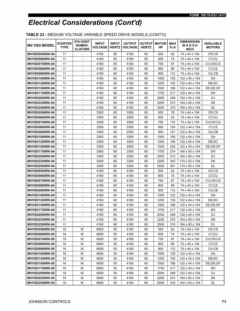
FORM 160.79-EG1 (417)
JOHNSON CONTROLS 71
Electrical Considerations (Cont'd)
MV VSD MODEL STARTER TYPE
9TH DIGIT NOMEN-
CLATURE
INPUT VOLTAGE
INPUT HERTZ
OUTPUT VOLTAGE
OUTPUT HERTZ
MOTOR HP
MAX FLA
DIMENSIONS W X D X H
INCH
AVAILABLE MOTORS
MVVSD0500RK-84 11 - 4160 60 4160 60 500 62 74 x 44 x 104 CR,CSMVVSD0600RK-84 11 - 4160 60 4160 60 600 74 74 x 44 x 104 CT,CUMVVSD0700RK-84 11 - 4160 60 4160 60 700 87 74 x 44 x 104 CV,CW,CXMVVSD0800RK-84 11 - 4160 60 4160 60 800 99 74 x 44 x 104 CY,CZMVVSD0900RK-84 11 - 4160 60 4160 60 900 112 74 x 44 x 104 CA,CBMVVSD1000RK-84 11 - 4160 60 4160 60 1000 125 122 x 44 x 104 DAMVVSD1250RK-84 11 - 4160 60 4160 60 1250 155 122 x 44 x 104 DB,DCMVVSD1500RK-84 11 - 4160 60 4160 60 1500 186 122 x 44 x 104 DD,DE,DFMVVSD1750RK-84 11 - 4160 60 4160 60 1750 217 122 x 44 x 104 DHMVVSD2000RK-84 11 - 4160 60 4160 60 2000 248 122 x 44 x 104 DJMVVSD2250RK-84 11 - 4160 60 4160 60 2250 274 164 x 50 x 104 DKMVVSD2500RK-84 11 - 4160 60 4160 60 2500 310 164 x 50 x 104 DLMVVSD0500RK-94 11 - 3300 60 3300 60 500 78 74 x 44 x 104 CR,CSMVVSD0600RK-94 11 - 3300 60 3300 60 600 93 74 x 44 x 104 CT,CUMVVSD0700RK-94 11 - 3300 60 3300 60 700 110 74 x 44 x 104 CV,CW,CXMVVSD0800RK-94 11 - 3300 60 3300 60 800 124 122 x 44 x 104 CY,CZMVVSD0900RK-94 11 - 3300 60 3300 60 900 141 122 x 44 x 104 CA,CBMVVSD1000RK-94 11 - 3300 60 3300 60 1000 156 122 x 44 x 104 DAMVVSD1250RK-94 11 - 3300 60 3300 60 1250 195 122 x 44 x 104 DB,DCMVVSD1500RK-94 11 - 3300 60 3300 60 1500 235 122 x 44 x 104 DD,DE,DFMVVSD1750RK-94 11 - 3300 60 3300 60 1750 274 164 x 50 x 104 DHMVVSD2000RK-94 11 - 3300 60 3300 60 2000 312 164 x 50 x 104 DJMVVSD2250RK-94 11 - 3300 60 3300 60 2250 345 174 x 50 x 104 DKMVVSD2500RK-94 11 - 3300 60 3300 60 2500 391 174 x 50 x 104 DLMVVSD0500RK-84 11 - 4160 60 4160 60 500 62 74 x 44 x 104 CR,CSMVVSD0600RK-84 11 - 4160 60 4160 60 600 74 74 x 44 x 104 CT,CUMVVSD0700RK-84 11 - 4160 60 4160 60 700 87 74 x 44 x 104 CV,CW,CXMVVSD0800RK-84 11 - 4160 60 4160 60 800 99 74 x 44 x 104 CY,CZMVVSD0900RK-84 11 - 4160 60 4160 60 900 112 74 x 44 x 104 CA,CBMVVSD1000RK-84 11 - 4160 60 4160 60 1000 125 122 x 44 x 104 DAMVVSD1250RK-84 11 - 4160 60 4160 60 1250 155 122 x 44 x 104 DB,DCMVVSD1500RK-84 11 - 4160 60 4160 60 1500 186 122 x 44 x 104 DD,DE,DFMVVSD1750RK-84 11 - 4160 60 4160 60 1750 217 122 x 44 x 104 DHMVVSD2000RK-84 11 - 4160 60 4160 60 2000 248 122 x 44 x 104 DJMVVSD2250RK-84 11 - 4160 60 4160 60 2250 274 164 x 50 x 104 DKMVVSD2500RK-84 11 - 4160 60 4160 60 2500 310 164 x 50 x 104 DLMVVSD0500RK-95 16 M 6600 50 4160 60 500 62 74 x 44 x 104 CR,CSMVVSD0600RK-95 16 M 6600 50 4160 60 600 74 74 x 44 x 104 CT,CUMVVSD0700RK-95 16 M 6600 50 4160 60 700 87 74 x 44 x 104 CV,CW,CXMVVSD0800RK-95 16 M 6600 50 4160 60 800 99 74 x 44 x 104 CY,CZMVVSD0900RK-95 16 M 6600 50 4160 60 900 112 74 x 44 x 104 CA,CBMVVSD1000RK-95 16 M 6600 50 4160 60 1000 125 122 x 44 x 104 DAMVVSD1250RK-95 16 M 6600 50 4160 60 1250 155 122 x 44 x 104 DB,DCMVVSD1500RK-95 16 M 6600 50 4160 60 1500 186 122 x 44 x 104 DD,DE,DFMVVSD1750RK-95 16 M 6600 50 4160 60 1750 217 122 x 44 x 104 DHMVVSD2000RK-95 16 M 6600 50 4160 60 2000 248 122 x 44 x 104 DJMVVSD2250RK-95 16 M 6600 50 4160 60 2250 274 164 x 50 x 104 DKMVVSD2500RK-95 16 M 6600 50 4160 60 2500 310 164 x 50 x 104 DL
TABLE 23 - MEDIUM VOLTAGE VARIABLE SPEED DRIVE MODELS (CONT'D)
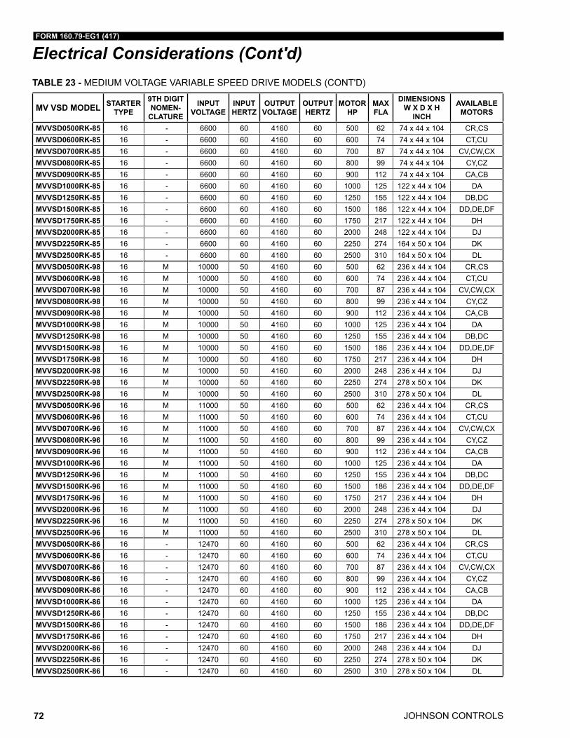
JOHNSON CONTROLS
FORM 160.79-EG1 (417)
72
Electrical Considerations (Cont'd)
MV VSD MODEL STARTER TYPE
9TH DIGIT NOMEN-
CLATURE
INPUT VOLTAGE
INPUT HERTZ
OUTPUT VOLTAGE
OUTPUT HERTZ
MOTOR HP
MAX FLA
DIMENSIONS W X D X H
INCH
AVAILABLE MOTORS
MVVSD0500RK-85 16 - 6600 60 4160 60 500 62 74 x 44 x 104 CR,CSMVVSD0600RK-85 16 - 6600 60 4160 60 600 74 74 x 44 x 104 CT,CUMVVSD0700RK-85 16 - 6600 60 4160 60 700 87 74 x 44 x 104 CV,CW,CXMVVSD0800RK-85 16 - 6600 60 4160 60 800 99 74 x 44 x 104 CY,CZMVVSD0900RK-85 16 - 6600 60 4160 60 900 112 74 x 44 x 104 CA,CBMVVSD1000RK-85 16 - 6600 60 4160 60 1000 125 122 x 44 x 104 DAMVVSD1250RK-85 16 - 6600 60 4160 60 1250 155 122 x 44 x 104 DB,DCMVVSD1500RK-85 16 - 6600 60 4160 60 1500 186 122 x 44 x 104 DD,DE,DFMVVSD1750RK-85 16 - 6600 60 4160 60 1750 217 122 x 44 x 104 DHMVVSD2000RK-85 16 - 6600 60 4160 60 2000 248 122 x 44 x 104 DJMVVSD2250RK-85 16 - 6600 60 4160 60 2250 274 164 x 50 x 104 DKMVVSD2500RK-85 16 - 6600 60 4160 60 2500 310 164 x 50 x 104 DLMVVSD0500RK-98 16 M 10000 50 4160 60 500 62 236 x 44 x 104 CR,CSMVVSD0600RK-98 16 M 10000 50 4160 60 600 74 236 x 44 x 104 CT,CUMVVSD0700RK-98 16 M 10000 50 4160 60 700 87 236 x 44 x 104 CV,CW,CXMVVSD0800RK-98 16 M 10000 50 4160 60 800 99 236 x 44 x 104 CY,CZMVVSD0900RK-98 16 M 10000 50 4160 60 900 112 236 x 44 x 104 CA,CBMVVSD1000RK-98 16 M 10000 50 4160 60 1000 125 236 x 44 x 104 DAMVVSD1250RK-98 16 M 10000 50 4160 60 1250 155 236 x 44 x 104 DB,DCMVVSD1500RK-98 16 M 10000 50 4160 60 1500 186 236 x 44 x 104 DD,DE,DFMVVSD1750RK-98 16 M 10000 50 4160 60 1750 217 236 x 44 x 104 DHMVVSD2000RK-98 16 M 10000 50 4160 60 2000 248 236 x 44 x 104 DJMVVSD2250RK-98 16 M 10000 50 4160 60 2250 274 278 x 50 x 104 DKMVVSD2500RK-98 16 M 10000 50 4160 60 2500 310 278 x 50 x 104 DLMVVSD0500RK-96 16 M 11000 50 4160 60 500 62 236 x 44 x 104 CR,CSMVVSD0600RK-96 16 M 11000 50 4160 60 600 74 236 x 44 x 104 CT,CUMVVSD0700RK-96 16 M 11000 50 4160 60 700 87 236 x 44 x 104 CV,CW,CXMVVSD0800RK-96 16 M 11000 50 4160 60 800 99 236 x 44 x 104 CY,CZMVVSD0900RK-96 16 M 11000 50 4160 60 900 112 236 x 44 x 104 CA,CBMVVSD1000RK-96 16 M 11000 50 4160 60 1000 125 236 x 44 x 104 DAMVVSD1250RK-96 16 M 11000 50 4160 60 1250 155 236 x 44 x 104 DB,DCMVVSD1500RK-96 16 M 11000 50 4160 60 1500 186 236 x 44 x 104 DD,DE,DFMVVSD1750RK-96 16 M 11000 50 4160 60 1750 217 236 x 44 x 104 DHMVVSD2000RK-96 16 M 11000 50 4160 60 2000 248 236 x 44 x 104 DJMVVSD2250RK-96 16 M 11000 50 4160 60 2250 274 278 x 50 x 104 DKMVVSD2500RK-96 16 M 11000 50 4160 60 2500 310 278 x 50 x 104 DLMVVSD0500RK-86 16 - 12470 60 4160 60 500 62 236 x 44 x 104 CR,CSMVVSD0600RK-86 16 - 12470 60 4160 60 600 74 236 x 44 x 104 CT,CUMVVSD0700RK-86 16 - 12470 60 4160 60 700 87 236 x 44 x 104 CV,CW,CXMVVSD0800RK-86 16 - 12470 60 4160 60 800 99 236 x 44 x 104 CY,CZMVVSD0900RK-86 16 - 12470 60 4160 60 900 112 236 x 44 x 104 CA,CBMVVSD1000RK-86 16 - 12470 60 4160 60 1000 125 236 x 44 x 104 DAMVVSD1250RK-86 16 - 12470 60 4160 60 1250 155 236 x 44 x 104 DB,DCMVVSD1500RK-86 16 - 12470 60 4160 60 1500 186 236 x 44 x 104 DD,DE,DFMVVSD1750RK-86 16 - 12470 60 4160 60 1750 217 236 x 44 x 104 DHMVVSD2000RK-86 16 - 12470 60 4160 60 2000 248 236 x 44 x 104 DJMVVSD2250RK-86 16 - 12470 60 4160 60 2250 274 278 x 50 x 104 DKMVVSD2500RK-86 16 - 12470 60 4160 60 2500 310 278 x 50 x 104 DL
TABLE 23 - MEDIUM VOLTAGE VARIABLE SPEED DRIVE MODELS (CONT'D)
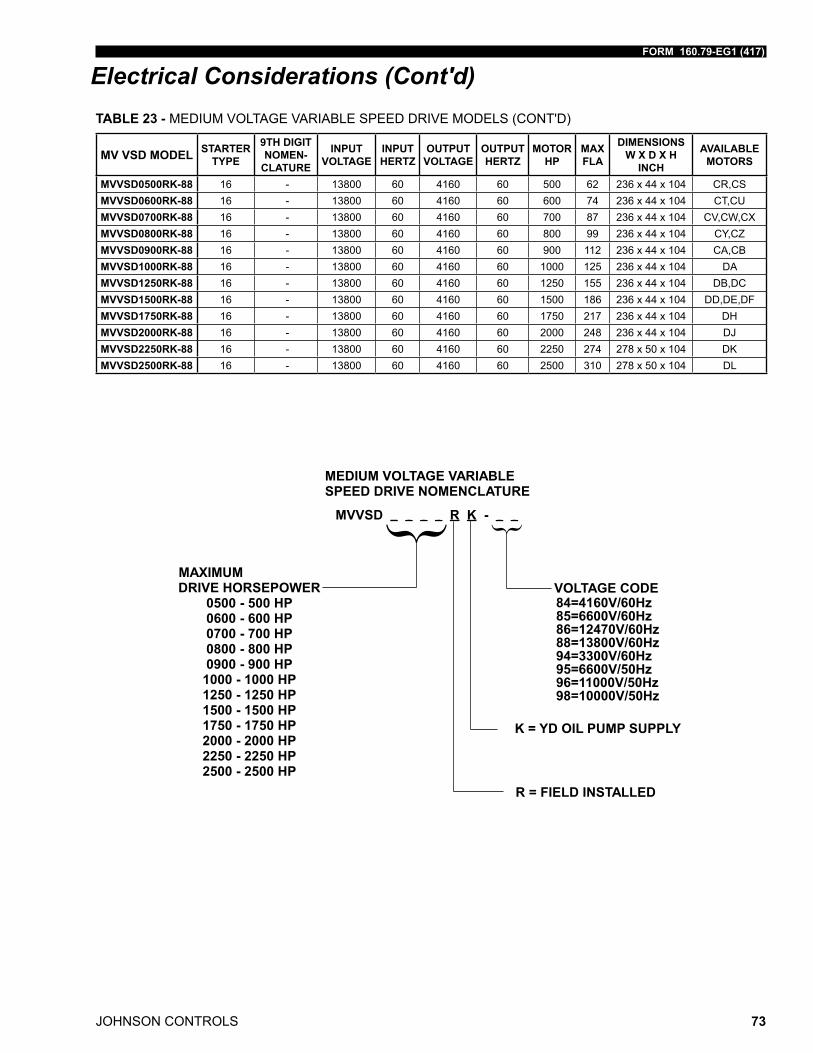
FORM 160.79-EG1 (417)
JOHNSON CONTROLS 73
Electrical Considerations (Cont'd)
MV VSD MODEL STARTER TYPE
9TH DIGIT NOMEN-
CLATURE
INPUT VOLTAGE
INPUT HERTZ
OUTPUT VOLTAGE
OUTPUT HERTZ
MOTOR HP
MAX FLA
DIMENSIONS W X D X H
INCH
AVAILABLE MOTORS
MVVSD0500RK-88 16 - 13800 60 4160 60 500 62 236 x 44 x 104 CR,CSMVVSD0600RK-88 16 - 13800 60 4160 60 600 74 236 x 44 x 104 CT,CUMVVSD0700RK-88 16 - 13800 60 4160 60 700 87 236 x 44 x 104 CV,CW,CXMVVSD0800RK-88 16 - 13800 60 4160 60 800 99 236 x 44 x 104 CY,CZMVVSD0900RK-88 16 - 13800 60 4160 60 900 112 236 x 44 x 104 CA,CBMVVSD1000RK-88 16 - 13800 60 4160 60 1000 125 236 x 44 x 104 DAMVVSD1250RK-88 16 - 13800 60 4160 60 1250 155 236 x 44 x 104 DB,DCMVVSD1500RK-88 16 - 13800 60 4160 60 1500 186 236 x 44 x 104 DD,DE,DFMVVSD1750RK-88 16 - 13800 60 4160 60 1750 217 236 x 44 x 104 DHMVVSD2000RK-88 16 - 13800 60 4160 60 2000 248 236 x 44 x 104 DJMVVSD2250RK-88 16 - 13800 60 4160 60 2250 274 278 x 50 x 104 DKMVVSD2500RK-88 16 - 13800 60 4160 60 2500 310 278 x 50 x 104 DL
TABLE 23 - MEDIUM VOLTAGE VARIABLE SPEED DRIVE MODELS (CONT'D)
{ {
K = YD OIL PUMP SUPPLY
84=4160V/60Hz85=6600V/60Hz86=12470V/60Hz88=13800V/60Hz94=3300V/60Hz95=6600V/50Hz96=11000V/50Hz98=10000V/50Hz
{ {
K = YD OIL PUMP SUPPLY
84=4160V/60Hz85=6600V/60Hz86=12470V/60Hz88=13800V/60Hz94=3300V/60Hz95=6600V/50Hz96=11000V/50Hz98=10000V/50Hz
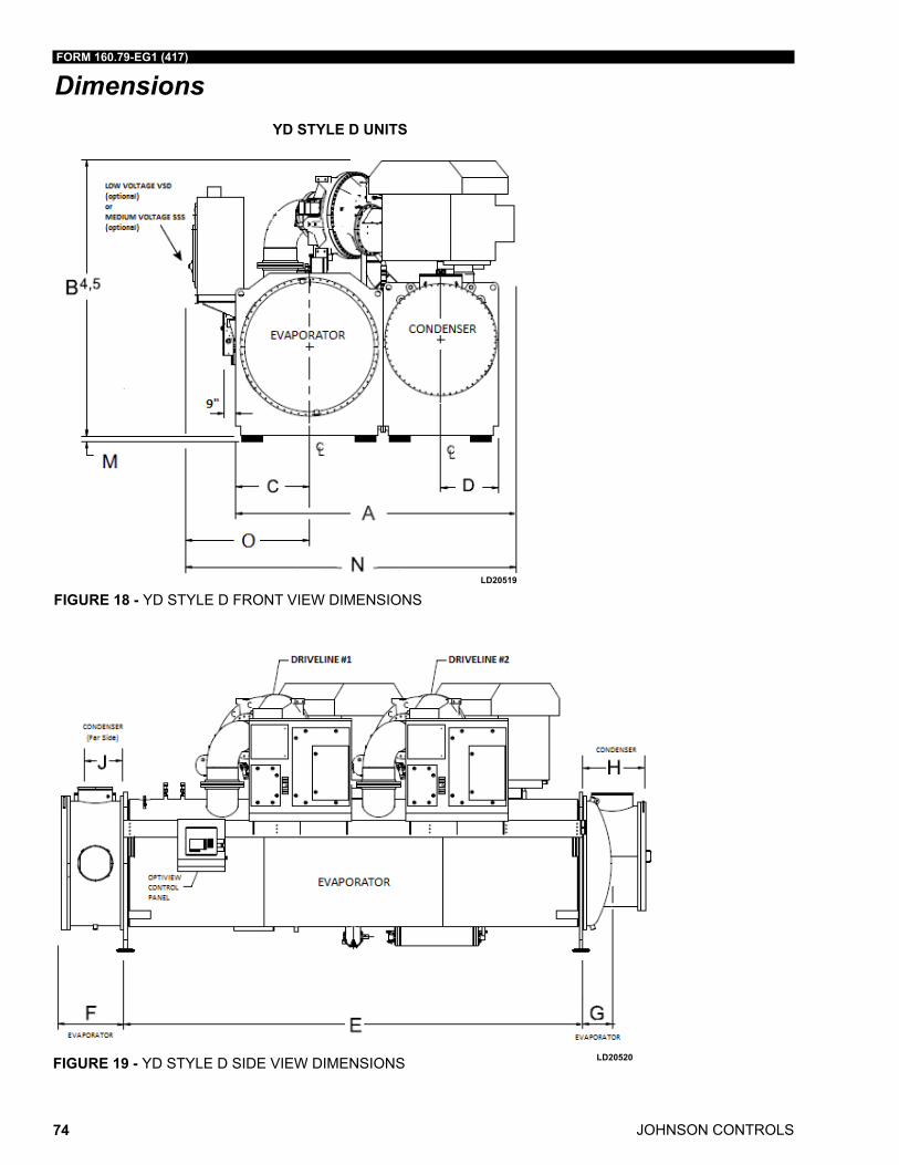
JOHNSON CONTROLS
FORM 160.79-EG1 (417)
74
Dimensions
LD20520
YD STYLE D UNITS
LD20519
FIGURE 18 - YD STYLE D FRONT VIEW DIMENSIONS
FIGURE 19 - YD STYLE D SIDE VIEW DIMENSIONS
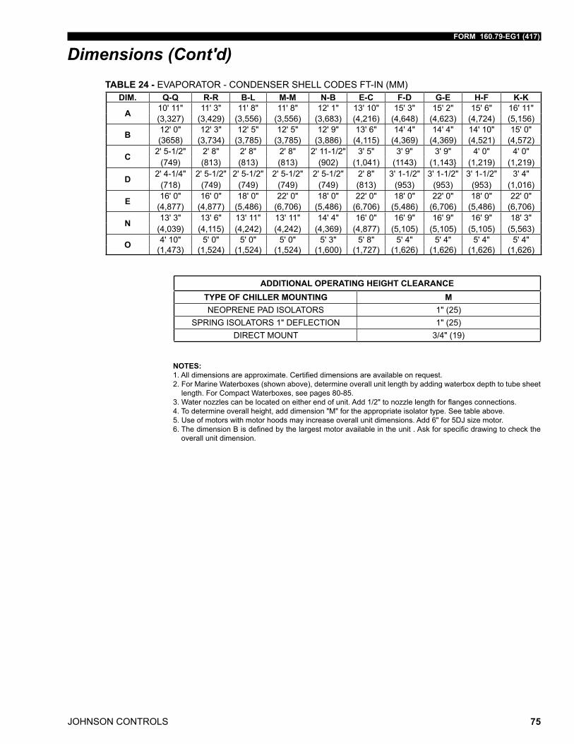
FORM 160.79-EG1 (417)
JOHNSON CONTROLS 75
Dimensions (Cont'd)
NOTES:1.Alldimensionsareapproximate.Certifieddimensionsareavailableonrequest.2. For Marine Waterboxes (shown above), determine overall unit length by adding waterbox depth to tube sheet
length. For Compact Waterboxes, see pages 80-85.3.Waternozzlescanbelocatedoneitherendofunit.Add1/2"tonozzlelengthforflangesconnections.4. To determine overall height, add dimension "M" for the appropriate isolator type. See table above.5. Use of motors with motor hoods may increase overall unit dimensions. Add 6" for 5DJ size motor.6.ThedimensionBisdefinedbythelargestmotoravailableintheunit.Askforspecificdrawingtocheckthe
overall unit dimension.
ADDITIONAL OPERATING HEIGHT CLEARANCETYPE OF CHILLER MOUNTING MNEOPRENE PAD ISOLATORS 1" (25)
SPRING ISOLATORS 1" DEFLECTION 1" (25)DIRECT MOUNT 3/4" (19)
DIM. Q-Q R-R B-L M-M N-B E-C F-D G-E H-F K-K
A 10' 11" 11' 3" 11' 8" 11' 8" 12' 1" 13' 10" 15' 3" 15' 2" 15' 6" 16' 11"(3,327) (3,429) (3,556) (3,556) (3,683) (4,216) (4,648) (4,623) (4,724) (5,156)
B 12' 0" 12' 3" 12' 5" 12' 5" 12' 9" 13' 6" 14' 4" 14' 4" 14' 10" 15' 0"(3658) (3,734) (3,785) (3,785) (3,886) (4,115) (4,369) (4,369) (4,521) (4,572)
C 2' 5-1/2" 2' 8" 2' 8" 2' 8" 2' 11-1/2" 3' 5" 3' 9" 3' 9" 4' 0" 4' 0"(749) (813) (813) (813) (902) (1,041) (1143) (1,143} (1,219) (1,219)
D 2' 4-1/4" 2' 5-1/2" 2' 5-1/2" 2' 5-1/2" 2' 5-1/2" 2' 8" 3' 1-1/2" 3' 1-1/2" 3' 1-1/2" 3' 4"(718) (749) (749) (749) (749) (813) (953) (953) (953) (1,016)
E 16' 0" 16' 0" 18' 0" 22' 0" 18' 0" 22' 0" 18' 0" 22' 0" 18' 0" 22' 0"(4,877) (4,877) (5,486) (6,706) (5,486) (6,706) (5,486) (6,706) (5,486) (6,706)
N 13' 3" 13' 6" 13' 11" 13' 11" 14' 4" 16' 0" 16' 9" 16' 9" 16' 9" 18' 3"(4,039) (4,115) (4,242) (4,242) (4,369) (4,877) (5,105) (5,105) (5,105) (5,563)
O 4' 10" 5' 0" 5' 0" 5' 0" 5' 3" 5' 8" 5' 4" 5' 4" 5' 4" 5' 4"(1,473) (1,524) (1,524) (1,524) (1,600) (1,727) (1,626) (1,626) (1,626) (1,626)
TABLE 24 - EVAPORATOR - CONDENSER SHELL CODES FT-IN (MM)
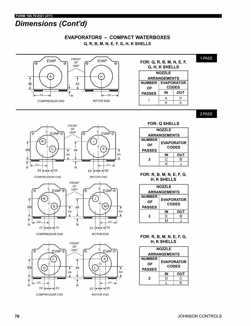
JOHNSON CONTROLS
FORM 160.79-EG1 (417)
76
Dimensions (Cont'd)
EVAPORATORS – COMPACT WATERBOXESQ, R, B, M, N, E, F, G, H, K SHELLS
LD08640
E
C K
D
C
L
K
NOZZLE ARRANGEMENTS
NUMBER OF
PASSES
EVAPORATOR CODES
IN OUT
1 A HH A
NOZZLE ARRANGEMENTS
NUMBER OF
PASSES
EVAPORATOR CODES
2IN OUTC BK J
NOZZLE ARRANGEMENTS
NUMBER OF
PASSES
EVAPORATOR CODES
2IN OUTE BM J
NOZZLE ARRANGEMENTS
NUMBER OF
PASSES
EVAPORATOR CODES
2IN OUTD CL K
FOR: Q, R, B, M, N, E, F, G, H, K SHELLS
FOR: R, B, M, N, E, F, G, H, K SHELLS
FOR: R, B, M, N, E, F, G, H, K SHELLS
FOR: Q SHELLS
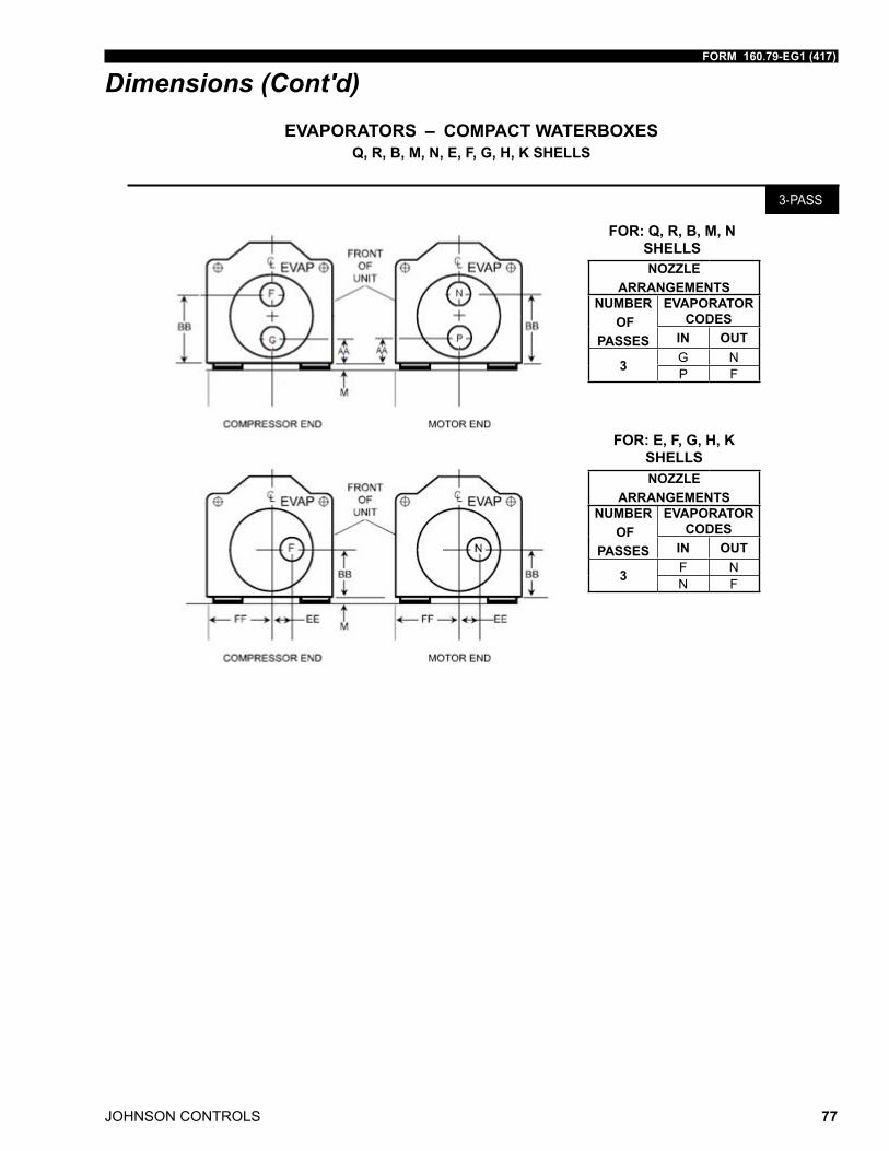
FORM 160.79-EG1 (417)
JOHNSON CONTROLS 77
Dimensions (Cont'd)EVAPORATORS – COMPACT WATERBOXES
Q, R, B, M, N, E, F, G, H, K SHELLS
NOZZLE ARRANGEMENTS
NUMBER OF
PASSES
EVAPORATOR CODES
IN OUT
3 G NP F
NOZZLE ARRANGEMENTS
NUMBER OF
PASSES
EVAPORATOR CODES
IN OUT
3 F NN F
FOR: Q, R, B, M, N SHELLS
FOR: E, F, G, H, K SHELLS
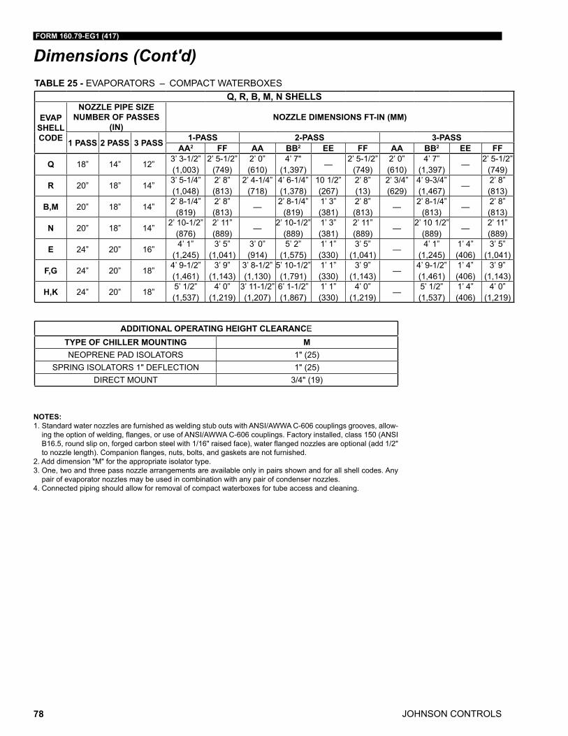
JOHNSON CONTROLS
FORM 160.79-EG1 (417)
78
Dimensions (Cont'd)TABLE 25 - EVAPORATORS – COMPACT WATERBOXES
Q, R, B, M, N SHELLS
EVAP SHELL CODE
NOZZLE PIPE SIZE NUMBER OF PASSES
(IN)NOZZLE DIMENSIONS FT-IN (MM)
1 PASS 2 PASS 3 PASS 1-PASS 2-PASS 3-PASSAA2 FF AA BB2 EE FF AA BB2 EE FF
Q 18” 14” 12”3’ 3-1/2” (1,003)
2’ 5-1/2” (749)
2’ 0” (610)
4’ 7" (1,397)
—2’ 5-1/2”
(749)2’ 0” (610)
4’ 7” (1,397)
—2’ 5-1/2”
(749)
R 20” 18” 14”3’ 5-1/4” (1,048)
2’ 8” (813)
2’ 4-1/4” (718)
4’ 6-1/4” (1,378)
10 1/2” (267)
2’ 8” (13)
2’ 3/4” (629)
4’ 9-3/4” (1,467)
—2’ 8” (813)
B,M 20” 18” 14”2’ 8-1/4”
(819)2’ 8” (813)
—2’ 8-1/4”
(819)1’ 3” (381)
2’ 8” (813)
—2’ 8-1/4”
(813)—
2’ 8” (813)
N 20” 18” 14”2’ 10-1/2”
(876)2’ 11” (889)
—2’ 10-1/2”
(889)1’ 3” (381)
2’ 11” (889)
—2’ 10 1/2”
(889)—
2’ 11” (889)
E 24” 20” 16”4’ 1”
(1,245)3’ 5”
(1,041)3’ 0” (914)
5’ 2” (1,575)
1’ 1” (330)
3’ 5” (1,041)
—4’ 1”
(1,245)1’ 4” (406)
3’ 5” (1,041)
F,G 24” 20” 18”4’ 9-1/2” (1,461)
3’ 9” (1,143)
3’ 8-1/2” (1,130)
5’ 10-1/2” (1,791)
1’ 1” (330)
3’ 9” (1,143)
—4’ 9-1/2” (1,461)
1’ 4” (406)
3’ 9” (1,143)
H,K 24” 20” 18”5’ 1/2” (1,537)
4’ 0” (1,219)
3’ 11-1/2” (1,207)
6’ 1-1/2” (1,867)
1’ 1” (330)
4’ 0” (1,219)
—5’ 1/2” (1,537)
1’ 4” (406)
4’ 0” (1,219)
NOTES:1. Standard water nozzles are furnished as welding stub outs with ANSI/AWWA C-606 couplings grooves, allow-ingtheoptionofwelding,flanges,oruseofANSI/AWWAC-606couplings.Factoryinstalled,class150(ANSIB16.5,roundslipon,forgedcarbonsteelwith1/16"raisedface),waterflangednozzlesareoptional(add1/2"tonozzlelength).Companionflanges,nuts,bolts,andgasketsarenotfurnished.
2. Add dimension "M" for the appropriate isolator type. 3. One, two and three pass nozzle arrangements are available only in pairs shown and for all shell codes. Any
pair of evaporator nozzles may be used in combination with any pair of condenser nozzles.4. Connected piping should allow for removal of compact waterboxes for tube access and cleaning.
ADDITIONAL OPERATING HEIGHT CLEARANCETYPE OF CHILLER MOUNTING MNEOPRENE PAD ISOLATORS 1" (25)
SPRING ISOLATORS 1" DEFLECTION 1" (25)DIRECT MOUNT 3/4" (19)
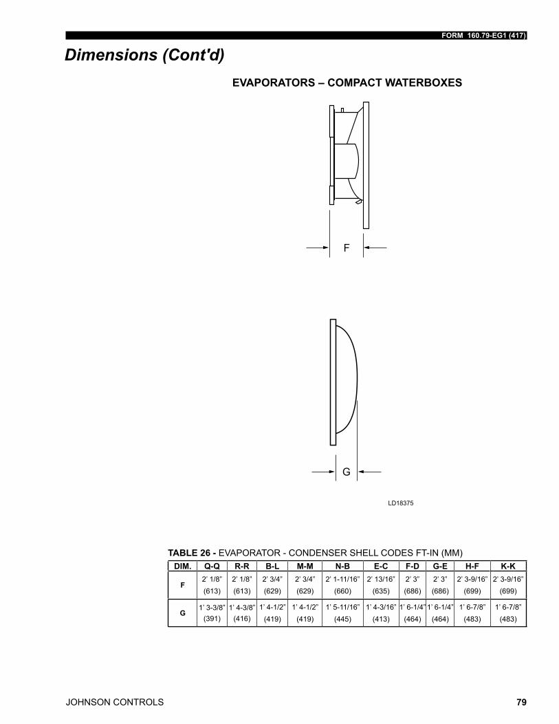
FORM 160.79-EG1 (417)
JOHNSON CONTROLS 79
Dimensions (Cont'd)EVAPORATORS – COMPACT WATERBOXES
TABLE 26 - EVAPORATOR - CONDENSER SHELL CODES FT-IN (MM)DIM. Q-Q R-R B-L M-M N-B E-C F-D G-E H-F K-K
F2’ 1/8” (613)
2’ 1/8” (613)
2’ 3/4”(629)
2’ 3/4”(629)
2’ 1-11/16”(660)
2’ 13/16”(635)
2’ 3” (686)
2’ 3” (686)
2’ 3-9/16”(699)
2’ 3-9/16”(699)
G1’ 3-3/8”
(391)1’ 4-3/8”
(416)1’ 4-1/2”
(419)1’ 4-1/2”
(419)1’ 5-11/16”
(445)1’ 4-3/16”
(413)1’ 6-1/4”
(464)1’ 6-1/4”
(464)1’ 6-7/8”
(483)1’ 6-7/8”
(483)
G
F
LD18375
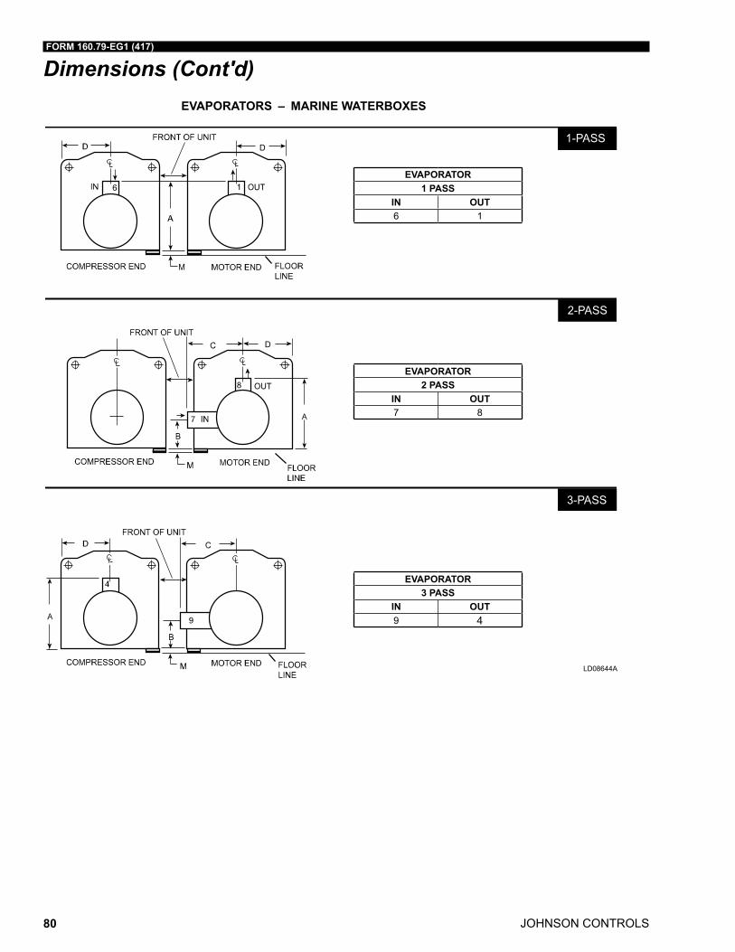
JOHNSON CONTROLS
FORM 160.79-EG1 (417)
80
Dimensions (Cont'd)EVAPORATORS – MARINE WATERBOXES
������
������
���������������������� �������� �����������
EVAPORATOR1 PASS
IN OUT6 1
EVAPORATOR2 PASS
IN OUT7 8
EVAPORATOR3 PASS
IN OUT9 4
LD08644A
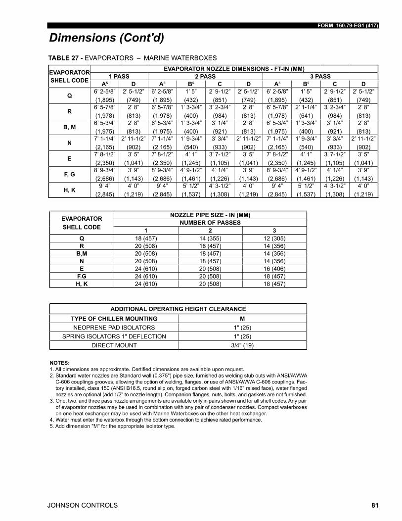
FORM 160.79-EG1 (417)
JOHNSON CONTROLS 81
Dimensions (Cont'd)TABLE 27 - EVAPORATORS – MARINE WATERBOXES
EVAPORATOR SHELL CODE
EVAPORATOR NOZZLE DIMENSIONS - FT-IN (MM)1 PASS 2 PASS 3 PASS
A5 D A5 B5 C D A5 B5 C D
Q6’ 2-5/8”(1,895)
2’ 5-1/2”(749)
6’ 2-5/8”(1,895)
1’ 5”(432)
2’ 9-1/2”(851)
2’ 5-1/2”(749)
6’ 2-5/8”(1,895)
1’ 5”(432)
2’ 9-1/2”(851)
2’ 5-1/2”(749)
R6’ 5-7/8”(1,978)
2’ 8”(813)
6’ 5-7/8”(1,978)
1’ 3-3/4”(400)
3’ 2-3/4”(984)
2’ 8”(813)
6’ 5-7/8”(1,978)
2’ 1-1/4”(641)
3’ 2-3/4”(984)
2’ 8”(813)
B, M6’ 5-3/4”(1,975)
2’ 8”(813)
6’ 5-3/4”(1,975)
1’ 3-3/4”(400)
3’ 1/4”(921)
2’ 8” (813)
6’ 5-3/4”(1,975)
1’ 3-3/4”(400)
3’ 1/4”(921)
2’ 8” (813)
N 7’ 1-1/4”(2,165)
2’ 11-1/2”(902)
7’ 1-1/4”(2,165)
1’ 9-3/4”(540)
3’ 3/4”(933)
2’ 11-1/2”(902)
7’ 1-1/4”(2,165)
1’ 9-3/4”(540)
3’ 3/4”(933)
2’ 11-1/2”(902)
E7’ 8-1/2”(2,350)
3’ 5” (1,041)
7’ 8-1/2”(2,350)
4’ 1” (1,245)
3’ 7-1/2”(1,105)
3’ 5” (1,041)
7’ 8-1/2”(2,350)
4’ 1” (1,245)
3’ 7-1/2”(1,105)
3’ 5” (1,041)
F, G8’ 9-3/4”(2,686)
3’ 9” (1,143)
8’ 9-3/4”(2,686)
4’ 9-1/2”(1,461)
4’ 1/4”(1,226)
3’ 9” (1,143)
8’ 9-3/4”(2,686)
4’ 9-1/2”(1,461)
4’ 1/4”(1,226)
3’ 9” (1,143)
H, K9’ 4”
(2,845)4’ 0”
(1,219)9’ 4”
(2,845)5’ 1/2”(1,537)
4’ 3-1/2”(1,308)
4’ 0” (1,219)
9’ 4” (2,845)
5’ 1/2”(1,537)
4’ 3-1/2”(1,308)
4’ 0” (1,219)
EVAPORATOR SHELL CODE
NOZZLE PIPE SIZE - IN (MM)NUMBER OF PASSES
1 2 3Q 18 (457) 14 (355) 12 (305)R 20 (508) 18 (457) 14 (356)
B,M 20 (508) 18 (457) 14 (356)N 20 (508) 18 (457) 14 (356)E 24 (610) 20 (508) 16 (406)
F.G 24 (610) 20 (508) 18 (457)H, K 24 (610) 20 (508) 18 (457)
NOTES:1.Alldimensionsareapproximate.Certifieddimensionsareavailableuponrequest.2. Standard water nozzles are Standard wall (0.375") pipe size, furnished as welding stub outs with ANSI/AWWA C-606couplingsgrooves,allowingtheoptionofwelding,flanges,oruseofANSI/AWWAC-606couplings.Fac-toryinstalled,class150(ANSIB16.5,roundslipon,forgedcarbonsteelwith1/16"raisedface),waterflangednozzlesareoptional(add1/2"tonozzlelength).Companionflanges,nuts,bolts,andgasketsarenotfurnished.
3. One, two, and three pass nozzle arrangements are available only in pairs shown and for all shell codes. Any pair of evaporator nozzles may be used in combination with any pair of condenser nozzles. Compact waterboxes on one heat exchanger may be used with Marine Waterboxes on the other heat exchanger.
4. Water must enter the waterbox through the bottom connection to achieve rated performance.5. Add dimension "M" for the appropriate isolator type.
ADDITIONAL OPERATING HEIGHT CLEARANCETYPE OF CHILLER MOUNTING MNEOPRENE PAD ISOLATORS 1" (25)
SPRING ISOLATORS 1" DEFLECTION 1" (25)DIRECT MOUNT 3/4" (19)
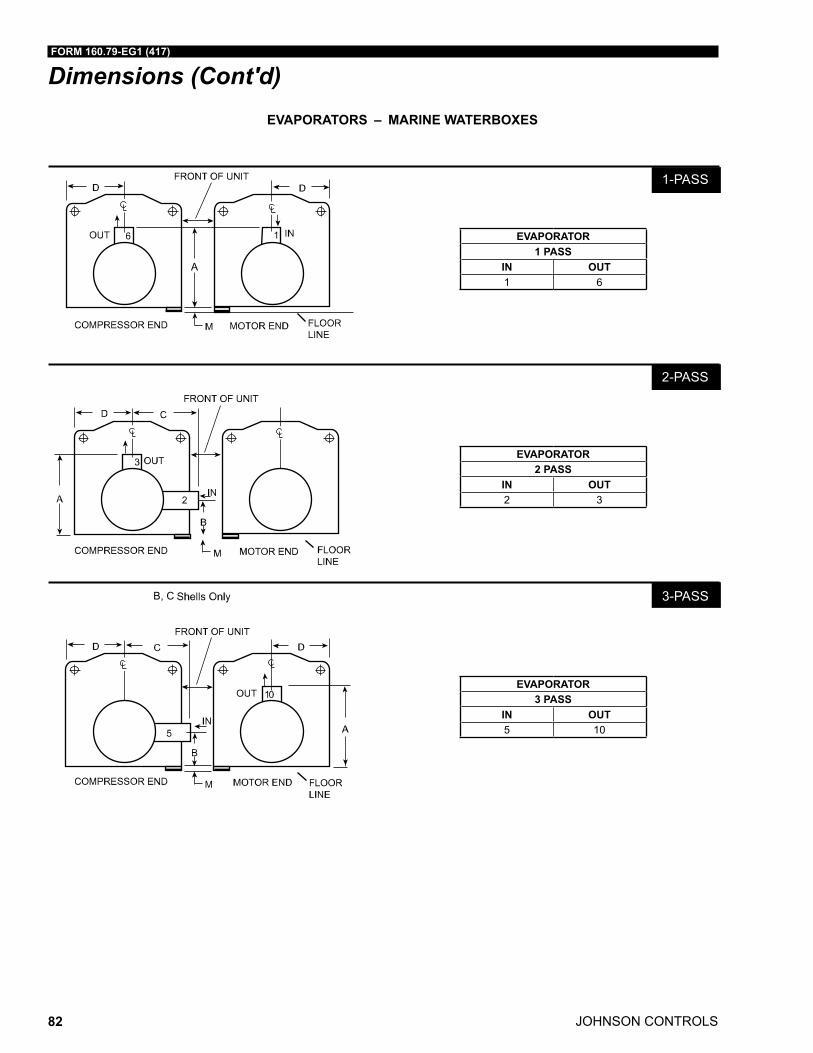
JOHNSON CONTROLS
FORM 160.79-EG1 (417)
82
Dimensions (Cont'd)EVAPORATORS – MARINE WATERBOXES
EVAPORATOR1 PASS
IN OUT1 6
EVAPORATOR2 PASS
IN OUT2 3
EVAPORATOR3 PASS
IN OUT5 10
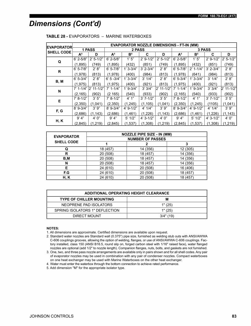
FORM 160.79-EG1 (417)
JOHNSON CONTROLS 83
Dimensions (Cont'd)TABLE 28 - EVAPORATORS – MARINE WATERBOXES
EVAPORATOR SHELL CODE
EVAPORATOR NOZZLE DIMENSIONS - FT-IN (MM)1 PASS 2 PASS 3 PASS
A5 D A5 B5 C D A5 B5 C D
Q6’ 2-5/8”(1,895)
2’ 5-1/2”(749)
6’ 2-5/8”(1,895)
1’ 5”(432)
2’ 9-1/2”(851)
2’ 5-1/2”(749)
6’ 2-5/8”(1,895)
1’ 5”(432)
2’ 9-1/2”(851)
2’ 5-1/2”(749)
R6’ 5-7/8”(1,978)
2’ 8”(813)
6’ 5-7/8”(1,978)
1’ 3-3/4”(400)
3’ 2-3/4”(984)
2’ 8”(813)
6’ 5-7/8”(1,978)
2’ 1-1/4”(641)
3’ 2-3/4”(984)
2’ 8”(813)
B, M6’ 5-3/4”(1,975)
2’ 8”(813)
6’ 5 -3/4”(1,975)
1’ 3-3/4”(400)
3’ 1/4”(921)
2’ 8” (813)
6’ 5-3/4”(1,975)
1' 3-3/4”(400)
3’ 1/4”(921)
2’ 8” (813)
N 7’ 1-1/4”(2,165)
2’ 11-1/2”(902)
7’ 1-1/4”(2 165)
1’ 9-3/4”(540)
3’ 3/4”(933)
2’ 11-1/2”(902)
7’ 1-1/4”(2,165)
1’ 9-3/4”(540)
3’ 3/4”(933)
2’ 11-1/2”(902)
E7’ 8-1/2”(2,350)
3’ 5” (1,041)
7’ 8-1/2”(2,350)
4’ 1” (1,245)
3’ 7-1/2”(1,105)
3’ 5” (1,041)
7’ 8-1/2”(2,350)
4’ 1” (1,245)
3’ 7-1/2”(1105)
3’ 5” (1,041)
F, G8’ 9-3/4”(2,686)
3’ 9” (1,143)
8’ 9-3/4”(2,686)
4’ 9-1/2”(1,461)
4’ 1/4”(1,226)
3’ 9” (1,143)
8’ 9-3/4”(2,686)
4’ 9-1/2”(1,461)
4’ 1/4”(1,226)
3’ 9” (1,143)
H, K9’ 4”
(2,845)4’ 0”
(1,219)9’ 4”
(2,845)5’ 1/2”(1,537)
4’ 3-1/2”(1,308)
4’ 0” (1,219)
9’ 4” (2,845)
5’ 1/2”(1,537)
4’ 3-1/2”(1,308)
4’ 0” (1,219)
NOTES:1.Alldimensionsareapproximate.Certifieddimensionsareavailableuponrequest.2. Standard water nozzles are Standard wall (0.375") pipe size, furnished as welding stub outs with ANSI/AWWA C-606couplingsgrooves,allowingtheoptionofwelding,flanges,oruseofANSI/AWWAC-606couplings.Fac-toryinstalled,class150(ANSIB16.5,roundslipon,forgedcarbonsteelwith1/16"raisedface),waterflangednozzlesareoptional(add1/2"tonozzlelength).Companionflanges,nuts,bolts,andgasketsarenotfurnished.
3. One, two, and three pass nozzle arrangements are available only in pairs shown and for all shell codes. Any pair of evaporator nozzles may be used in combination with any pair of condenser nozzles. Compact waterboxes on one heat exchanger may be used with Marine Waterboxes on the other heat exchanger.
4. Water must enter the waterbox through the bottom connection to achieve rated performance.5. Add dimension "M" for the appropriate isolator type.
ADDITIONAL OPERATING HEIGHT CLEARANCETYPE OF CHILLER MOUNTING MNEOPRENE PAD ISOLATORS 1" (25)
SPRING ISOLATORS 1" DEFLECTION 1" (25)DIRECT MOUNT 3/4" (19)
EVAPORATOR SHELL CODE
NOZZLE PIPE SIZE - IN (MM)NUMBER OF PASSES
1 2 3Q 18 (457) 14 (356) 12 (305)R 20 (508) 18 (457) 14 (356)
B,M 20 (508) 18 (457) 14 (356)N 20 (508) 18 (457) 14 (356)E 24 (610) 20 (508) 16 (406)
F.G 24 (610) 20 (508) 18 (457)H, K 24 (610) 20 (508) 18 (457)
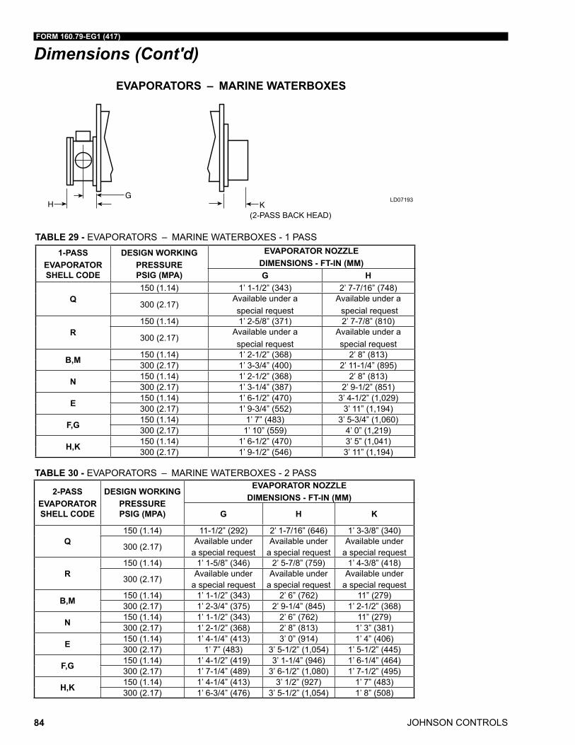
JOHNSON CONTROLS
FORM 160.79-EG1 (417)
84
Dimensions (Cont'd)
EVAPORATORS – MARINE WATERBOXES
(2-PASS BACK HEAD)
LD07193
1-PASSEVAPORATOR SHELL CODE
DESIGN WORKING PRESSURE PSIG (MPA)
EVAPORATOR NOZZLE DIMENSIONS - FT-IN (MM)G H
Q150 (1.14) 1’ 1-1/2” (343) 2’ 7-7/16” (748)
300 (2.17)Available under a special request
Available under a special request
R150 (1.14) 1’ 2-5/8” (371) 2’ 7-7/8” (810)
300 (2.17)Available under a special request
Available under a special request
B,M 150 (1.14) 1’ 2-1/2” (368) 2’ 8” (813)300 (2.17) 1’ 3-3/4” (400) 2’ 11-1/4” (895)
N 150 (1.14) 1’ 2-1/2” (368) 2’ 8” (813)300 (2.17) 1’ 3-1/4” (387) 2’ 9-1/2” (851)
E 150 (1.14) 1’ 6-1/2” (470) 3’ 4-1/2” (1,029)300 (2.17) 1’ 9-3/4” (552) 3’ 11” (1,194)
F,G 150 (1.14) 1’ 7” (483) 3’ 5-3/4” (1,060)300 (2.17) 1’ 10” (559) 4’ 0” (1,219)
H,K 150 (1.14) 1’ 6-1/2” (470) 3’ 5” (1,041)300 (2.17) 1’ 9-1/2” (546) 3’ 11” (1,194)
TABLE 29 - EVAPORATORS – MARINE WATERBOXES - 1 PASS
2-PASSEVAPORATOR SHELL CODE
DESIGN WORKING PRESSURE PSIG (MPA)
EVAPORATOR NOZZLE DIMENSIONS - FT-IN (MM)
G H K
Q150 (1.14) 11-1/2” (292) 2’ 1-7/16” (646) 1’ 3-3/8” (340)
300 (2.17)Available under
a special requestAvailable under
a special requestAvailable under
a special request
R150 (1.14) 1’ 1-5/8” (346) 2’ 5-7/8” (759) 1’ 4-3/8” (418)
300 (2.17)Available under
a special requestAvailable under
a special requestAvailable under
a special request
B,M 150 (1.14) 1’ 1-1/2” (343) 2’ 6” (762) 11” (279)300 (2.17) 1’ 2-3/4” (375) 2’ 9-1/4” (845) 1’ 2-1/2” (368)
N 150 (1.14) 1’ 1-1/2” (343) 2’ 6” (762) 11” (279)300 (2.17) 1’ 2-1/2” (368) 2’ 8” (813) 1’ 3” (381)
E 150 (1.14) 1’ 4-1/4” (413) 3’ 0” (914) 1’ 4” (406)300 (2.17) 1’ 7” (483) 3’ 5-1/2” (1,054) 1’ 5-1/2” (445)
F,G 150 (1.14) 1’ 4-1/2” (419) 3’ 1-1/4” (946) 1’ 6-1/4” (464)300 (2.17) 1’ 7-1/4” (489) 3’ 6-1/2” (1,080) 1’ 7-1/2” (495)
H,K 150 (1.14) 1’ 4-1/4” (413) 3’ 1/2” (927) 1’ 7” (483)300 (2.17) 1’ 6-3/4” (476) 3’ 5-1/2” (1,054) 1’ 8” (508)
TABLE 30 - EVAPORATORS – MARINE WATERBOXES - 2 PASS
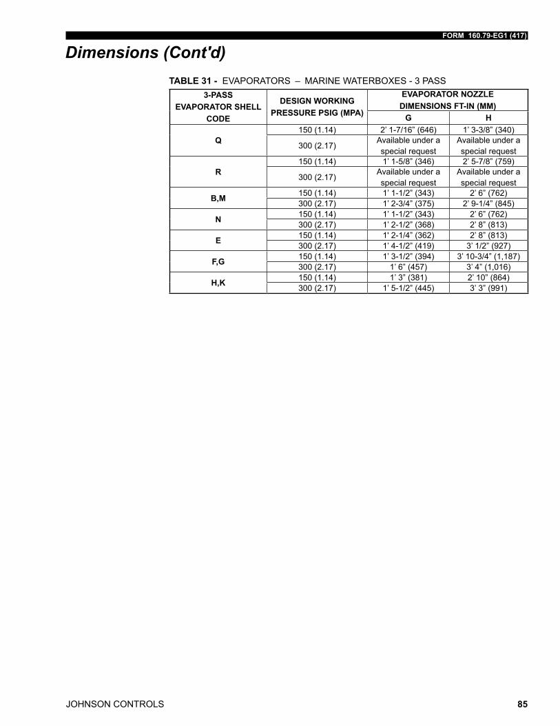
FORM 160.79-EG1 (417)
JOHNSON CONTROLS 85
Dimensions (Cont'd)TABLE 31 - EVAPORATORS – MARINE WATERBOXES - 3 PASS
3-PASSEVAPORATOR SHELL
CODE
DESIGN WORKING PRESSURE PSIG (MPA)
EVAPORATOR NOZZLE DIMENSIONS FT-IN (MM)
G H
Q150 (1.14) 2’ 1-7/16” (646) 1’ 3-3/8” (340)
300 (2.17)Available under a special request
Available under a special request
R150 (1.14) 1’ 1-5/8” (346) 2’ 5-7/8” (759)
300 (2.17)Available under a special request
Available under a special request
B,M 150 (1.14) 1’ 1-1/2” (343) 2’ 6” (762)300 (2.17) 1’ 2-3/4” (375) 2’ 9-1/4” (845)
N 150 (1.14) 1’ 1-1/2” (343) 2’ 6” (762)300 (2.17) 1’ 2-1/2” (368) 2’ 8” (813)
E 150 (1.14) 1' 2-1/4” (362) 2’ 8” (813)300 (2.17) 1’ 4-1/2” (419) 3’ 1/2” (927)
F,G 150 (1.14) 1’ 3-1/2” (394) 3’ 10-3/4” (1,187)300 (2.17) 1’ 6” (457) 3’ 4” (1,016)
H,K 150 (1.14) 1’ 3” (381) 2’ 10” (864)300 (2.17) 1’ 5-1/2” (445) 3’ 3” (991)
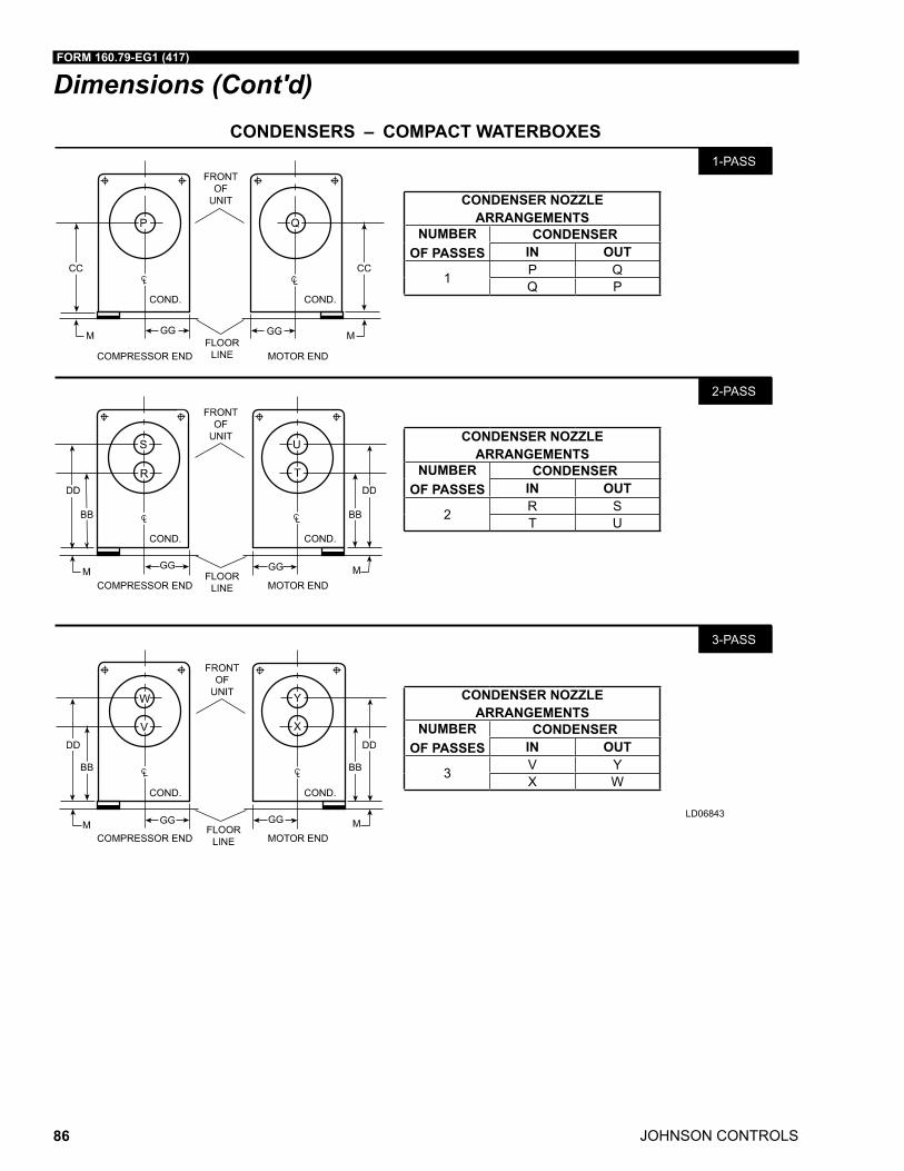
JOHNSON CONTROLS
FORM 160.79-EG1 (417)
86
Dimensions (Cont'd)CONDENSERS – COMPACT WATERBOXES
LD06843
CONDENSER NOZZLE ARRANGEMENTS
NUMBEROF PASSES
CONDENSERIN OUT
1 P QQ P
CONDENSER NOZZLE ARRANGEMENTS
NUMBEROF PASSES
CONDENSERIN OUT
2 R ST U
CONDENSER NOZZLE ARRANGEMENTS
NUMBEROF PASSES
CONDENSERIN OUT
3 V YX W
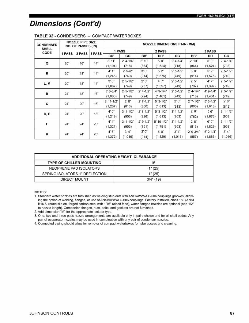
FORM 160.79-EG1 (417)
JOHNSON CONTROLS 87
Dimensions (Cont'd)
NOTES:1. Standard water nozzles are furnished as welding stub outs with ANSI/AWWA C-606 couplings grooves, allow-ingtheoptionofwelding,flanges,oruseofANSI/AWWAC-606couplings.Factoryinstalled,class150(ANSIB16.5,roundslipon,forgedcarbonsteelwith1/16"raisedface),waterflangednozzlesareoptional(add1/2"tonozzlelength).Companionflanges,nuts,bolts,andgasketsarenotfurnished.
2. Add dimension "M" for the appropriate isolator type. 3. One, two and three pass nozzle arrangements are available only in pairs shown and for all shell codes. Any
pair of evaporator nozzles may be used in combination with any pair of condenser nozzles.4. Connected piping should allow for removal of compact waterboxes for tube access and cleaning.
TABLE 32 - CONDENSERS – COMPACT WATERBOXES
CONDENSER SHELL CODE
NOZZLE PIPE SIZE NO. OF PASSES (IN) NOZZLE DIMENSIONS FT-IN (MM)
1 PASS 2 PASS 3 PASS1 PASS 2 PASS 3 PASS
CC2 GG BB2 DD2 GG BB2 DD GG
Q 20” 16” 14”3’ 11”
(1,194)2’ 4-1/4”
(718)2’ 10” (864)
5’ 0” (1,524)
2’ 4-1/4” (718)
2’ 10” (864)
5’ 0” (1,524)
2’ 4-1/4” (718)
R 20” 18” 14”4’ 1”
(1,245)2’ 5-/2” (749)
3’ 0” (914)
5’ 2” (1,575)
2’ 5-1/2” (749)
3’ 0” (914)
5’ 2” (1,575)
2’ 5-1/2” (749)
L, M 20” 18” 14”3’ 6”
(1,067)2’ 5-1/2”
(749)2’ 5” (737)
4’ 7” (1,397)
2’ 5-1/2” (749)
2’ 5” (737)
4’ 7” (1,397)
2’ 5-1/2” (749)
B 24” 18” 16”3’ 6-3/4” (1,086)
2’ 5-1/2” (749)
2’ 4-1/2” (724)
4’ 9-1/4” (1,461)
2’ 5-1/2” (749)
2’ 4-1/4” (718)
4’ 9-1/4” (1,461)
2’ 5-1/2” (749)
C 24” 20” 16”3’ 11-1/2” (1,207)
2’ 8” (813)
2’ 7-1/2” (800)
5’ 3-1/2” (1,613)
2’ 8” (813)
2’ 7-1/2” (800)
5’ 3-1/2” (1,613)
2’ 8” (813)
D, E 24” 20” 18”4’ 0”
(1,219)3’ 1-1/2”
(953)2’ 8-1/2”
(826)5’ 3-1/2” (1,613)
3’ 1-1/2” (953)
2’ 6” (762)
5 6” (1,676)
3’ 1-1/2” (953)
F 24” 24” 20”4’ 4”
(1,321)3’ 1-1/2”
(953)2’ 9-1/2”
(851)5’ 10-1/2” (1,791)
3’ 1-1/2” (953)
2’ 8” (813)
6’ 0” (1,829)
3’ 1-1/2” (953)
K 24” 24” 20”4’ 6”
(1,372)3’ 4”
(1,016)3’ 0” (914)
6’ 0” (1,829)
3’ 4” (1,016)
2’ 9-3/4” (857)
6’ 2-1/4” (1,886)
3’ 4” (1,016)
ADDITIONAL OPERATING HEIGHT CLEARANCETYPE OF CHILLER MOUNTING MNEOPRENE PAD ISOLATORS 1" (25)
SPRING ISOLATORS 1" DEFLECTION 1" (25)DIRECT MOUNT 3/4" (19)
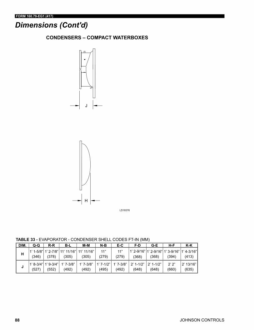
JOHNSON CONTROLS
FORM 160.79-EG1 (417)
88
Dimensions (Cont'd)CONDENSERS – COMPACT WATERBOXES
LD18376
�
�
TABLE 33 - EVAPORATOR - CONDENSER SHELL CODES FT-IN (MM)DIM. Q-Q R-R B-L M-M N-B E-C F-D G-E H-F K-K
H 1’ 1-5/8” (346)
1’ 2-7/8” (378)
11’ 11/16” (305)
11’ 11/16” (305)
11” (279)
11” (279)
1’ 2-9/16”(368)
1’ 2-9/16” (368)
1’ 3-9/16” (394)
1’ 4-3/16” (413)
J 1’ 8-3/4” (527)
1’ 9-3/4” (552)
1’ 7-3/8” (492)
1’ 7-3/8” (492)
1’ 7-1/2” (495)
1’ 7-3/8” (492)
2’ 1-1/2” (648)
2’ 1-1/2” (648)
2’ 2” (660)
2’ 13/16” (635)
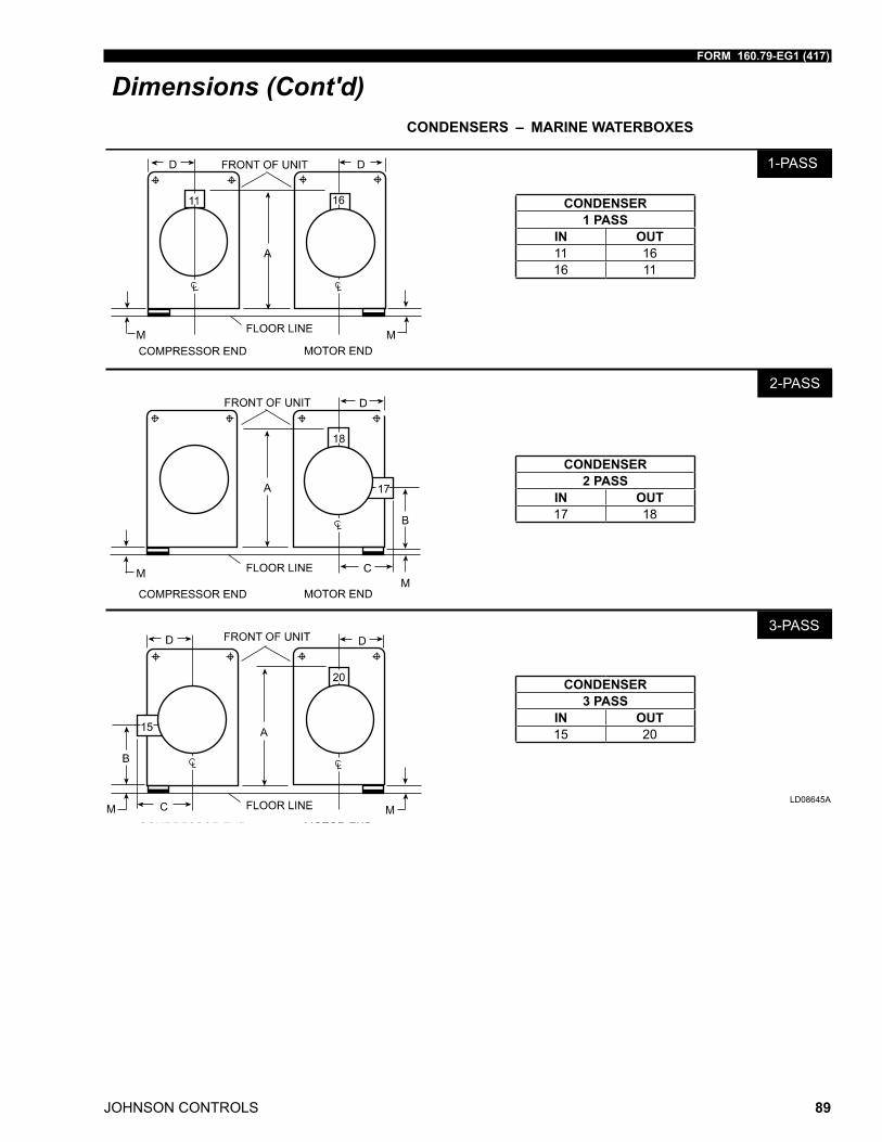
FORM 160.79-EG1 (417)
JOHNSON CONTROLS 89
Dimensions (Cont'd)CONDENSERS – MARINE WATERBOXES
������
������
������
CONDENSER1 PASS
IN OUT11 1616 11
CONDENSER2 PASS
IN OUT17 18
CONDENSER3 PASS
IN OUT15 20
LD08645A
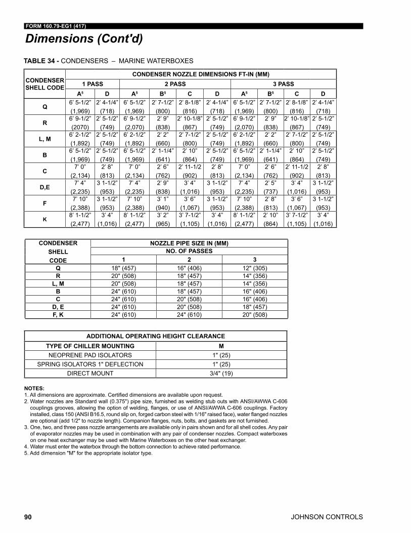
JOHNSON CONTROLS
FORM 160.79-EG1 (417)
90
Dimensions (Cont'd)TABLE 34 - CONDENSERS – MARINE WATERBOXES
CONDENSER SHELL CODE
CONDENSER NOZZLE DIMENSIONS FT-IN (MM)1 PASS 2 PASS 3 PASS
A5 D A5 B5 C D A5 B5 C D
Q6’ 5-1/2”(1,969)
2’ 4-1/4”(718)
6’ 5-1/2”(1,969)
2’ 7-1/2”(800)
2’ 8-1/8”(816)
2’ 4-1/4”(718)
6’ 5-1/2”(1,969)
2’ 7-1/2”(800)
2’ 8-1/8”(816)
2’ 4-1/4”(718)
R6’ 9-1/2”(2070)
2’ 5-1/2”(749)
6’ 9-1/2”(2,070)
2’ 9”(838)
2’ 10-1/8”(867)
2’ 5-1/2”(749)
6’ 9-1/2”(2,070)
2’ 9”(838)
2’ 10-1/8”(867)
2’ 5-1/2”(749)
L, M6’ 2-1/2”(1,892)
2’ 5-1/2”(749)
6’ 2-1/2”(1,892)
2’ 2” (660)
2’ 7-1/2”(800)
2’ 5-1/2”(749)
6’ 2-1/2”(1,892)
2’ 2” (660)
2’ 7-1/2”(800)
2’ 5-1/2”(749)
B6’ 5-1/2”(1,969)
2’ 5-1/2”(749)
6’ 5-1/2”(1,969)
2’ 1-1/4”(641)
2’ 10”(864)
2’ 5-1/2”(749)
6’ 5-1/2”(1,969)
2’ 1-1/4”(641)
2’ 10”(864)
2’ 5-1/2”(749)
C7’ 0”
(2,134)2’ 8” (813)
7’ 0”(2,134)
2’ 6” (762)
2’ 11-1/2(902)
2’ 8” (813)
7’ 0”(2,134)
2’ 6” (762)
2’ 11-1/2(902)
2’ 8” (813)
D,E7’ 4”
(2,235)3 1-1/2”(953)
7’ 4”(2,235)
2’ 9” (838)
3’ 4” (1,016)
3 1-1/2”(953)
7’ 4”(2,235)
2’ 5” (737)
3’ 4” (1,016)
3 1-1/2”(953)
F7’ 10”
(2,388)3 1-1/2”(953)
7’ 10”(2,388)
3’ 1” (940)
3’ 6”(1,067)
3 1-1/2”(953)
7’ 10”(2,388)
2’ 8” (813)
3’ 6”(1,067)
3 1-1/2”(953)
K8’ 1-1/2”(2,477)
3’ 4” (1,016)
8’ 1-1/2”(2,477)
3’ 2” (965)
3’ 7-1/2”(1,105)
3’ 4” (1,016)
8’ 1-1/2”(2,477)
2’ 10”(864)
3’ 7-1/2”(1,105)
3’ 4” (1,016)
NOTES:1.Alldimensionsareapproximate.Certifieddimensionsareavailableuponrequest.2. Water nozzles are Standard wall (0.375") pipe size, furnished as welding stub outs with ANSI/AWWA C-606 couplingsgrooves,allowingtheoptionofwelding,flanges,oruseofANSI/AWWAC-606couplings.Factoryinstalled,class150(ANSIB16.5,roundslipon,forgedcarbonsteelwith1/16"raisedface),waterflangednozzlesareoptional(add1/2"tonozzlelength).Companionflanges,nuts,bolts,andgasketsarenotfurnished.
3. One, two, and three pass nozzle arrangements are available only in pairs shown and for all shell codes. Any pair of evaporator nozzles may be used in combination with any pair of condenser nozzles. Compact waterboxes on one heat exchanger may be used with Marine Waterboxes on the other heat exchanger.
4. Water must enter the waterbox through the bottom connection to achieve rated performance.5. Add dimension "M" for the appropriate isolator type.
ADDITIONAL OPERATING HEIGHT CLEARANCETYPE OF CHILLER MOUNTING MNEOPRENE PAD ISOLATORS 1" (25)
SPRING ISOLATORS 1" DEFLECTION 1" (25)DIRECT MOUNT 3/4" (19)
CONDENSER SHELL CODE
NOZZLE PIPE SIZE IN (MM)NO. OF PASSES
1 2 3Q 18" (457) 16" (406) 12" (305)R 20" (508) 18" (457) 14" (356)
L, M 20" (508) 18" (457) 14" (356)B 24" (610) 18" (457) 16" (406)C 24" (610) 20" (508) 16" (406)
D, E 24" (610) 20" (508) 18" (457)F, K 24" (610) 24" (610) 20" (508)
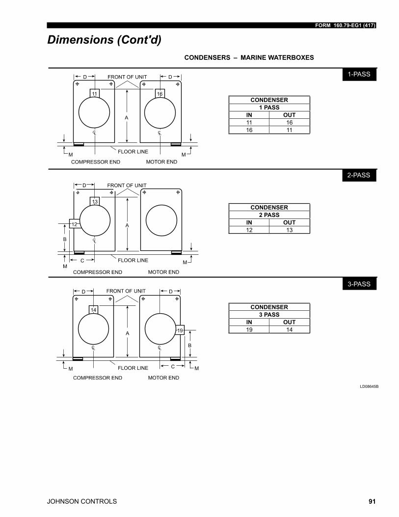
FORM 160.79-EG1 (417)
JOHNSON CONTROLS 91
Dimensions (Cont'd)CONDENSERS – MARINE WATERBOXES
CONDENSER1 PASS
IN OUT11 1616 11
CONDENSER2 PASS
IN OUT12 13
CONDENSER3 PASS
IN OUT19 14
LD08645B
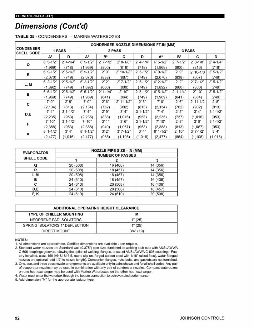
JOHNSON CONTROLS
FORM 160.79-EG1 (417)
92
Dimensions (Cont'd)
NOTES:1.Alldimensionsareapproximate.Certifieddimensionsareavailableuponrequest.2. Standard water nozzles are Standard wall (0.375") pipe size, furnished as welding stub outs with ANSI/AWWA C-606couplingsgrooves,allowingtheoptionofwelding,flanges,oruseofANSI/AWWAC-606couplings.Fac-toryinstalled,class150(ANSIB16.5,roundslipon,forgedcarbonsteelwith1/16"raisedface),waterflangednozzlesareoptional(add1/2"tonozzlelength).Companionflanges,nuts,bolts,andgasketsarenotfurnished.
3. One, two, and three pass nozzle arrangements are available only in pairs shown and for all shell codes. Any pair of evaporator nozzles may be used in combination with any pair of condenser nozzles. Compact waterboxes on one heat exchanger may be used with Marine Waterboxes on the other heat exchanger.
4. Water must enter the waterbox through the bottom connection to achieve rated performance.5. Add dimension "M" for the appropriate isolator type.
ADDITIONAL OPERATING HEIGHT CLEARANCETYPE OF CHILLER MOUNTING MNEOPRENE PAD ISOLATORS 1" (25)
SPRING ISOLATORS 1" DEFLECTION 1" (25)DIRECT MOUNT 3/4" (19)
TABLE 35 - CONDENSERS – MARINE WATERBOXES
CONDENSER SHELL CODE
CONDENSER NOZZLE DIMENSIONS FT-IN (MM)1 PASS 2 PASS 3 PASS
A5 D A5 B5 C D A5 B5 C D
Q6’ 5-1/2”(1,969)
2’ 4-1/4”(718)
6’ 5-1/2”(1,969)
2’ 7-1/2”(800)
2’ 8-1/8”(816)
2’ 4-1/4”(718)
6’ 5-1/2”(1,969)
2’ 7-1/2”(800)
2’ 8-1/8”(816)
2’ 4-1/4”(718)
R6’ 9-1/2”(2,070)
2’ 5-1/2”(749)
6’ 9-1/2”(2,070)
2’ 9”(838)
2’ 10-1/8”(867)
2’ 5-1/2”(749)
6’ 9-1/2”(2,070)
2’ 9”(838)
2’ 10-1/8 (867)
2’ 5-1/2”(749)
L, M6’ 2-1/2”(1,892)
2’ 5-1/2”(749)
6’ 2-1/2”(1,892)
2’ 2” (660)
2’ 7-1/2”(800)
2’ 5-1/2”(749)
6’ 2-1/2”(1,892)
2’ 2” (660)
2’ 7-1/2”(800)
2’ 5-1/2”(749)
B6’ 5-1/2”(1,969)
2’ 5-1/2”(749)
6’ 5-1/2”(1,969)
2’ 1-1/4”(641)
2’ 10”(864)
2’ 5-1/2”(749)
6’ 5-1/2”(1,969)
2’ 1-1/4”(641)
2’ 10”(864)
2’ 5-1/2”(749)
C7’ 0”
(2,134)2’ 8” (813)
7’ 0”(2,134)
2’ 6” (762)
2’ 11-1/2” (902)
2’ 8” (813)
7’ 0”(2,134)
2’ 6” (762)
2’ 11-1/2(902)
2’ 8” (813)
D,E7’ 4”
(2,235)3 1-1/2”(953)
7’ 4”(2,235)
2’ 9” (838)
3’ 4”(1,016)
3 1-1/2”(953)
7’ 4”(2,235)
2’ 5” (737)
3’ 4”(1,016)
3 1-1/2”(953)
F7’ 10”
(2,388)3 1-1/2”(953)
7’ 10”(2,388)
3’ 1” (940)
3’ 6”(1,067)
3 1-1/2”(953)
7’ 10”(2,388)
2’ 8” (813)
3’ 6”(1,067)
3 1-1/2”(953)
K8’ 1-1/2”(2,477)
3’ 4”(1,016)
8’ 1-1/2”(2,477)
3’ 2” (965)
3’ 7-1/2”(1,105)
3’ 4”(1,016)
8’ 1-1/2”(2,477)
2’ 10”(864)
3’ 7-1/2”(1,105)
3’ 4”(1,016)
EVAPORATOR SHELL CODE
NOZZLE PIPE SIZE - IN (MM)NUMBER OF PASSES
1 2 3Q 20 (508) 16 (406) 14 (356)R 20 (508) 18 (457) 14 (356)
L,M 20 (508) 18 (457) 14 (356)B 24 (610) 18 (457) 16 (406)C 24 (610) 20 (508) 16 (406)
D,E 24 (610) 20 (508) 18 (457)F, K 24 (610) 24 (610) 20 (508)
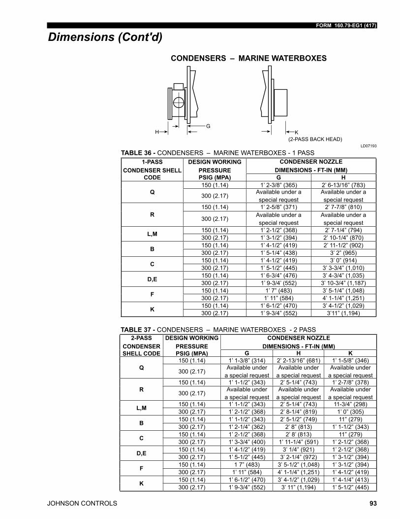
FORM 160.79-EG1 (417)
JOHNSON CONTROLS 93
Dimensions (Cont'd)CONDENSERS – MARINE WATERBOXES
(2-PASS BACK HEAD)LD07193
1-PASSCONDENSER SHELL
CODE
DESIGN WORKING PRESSURE PSIG (MPA)
CONDENSER NOZZLE DIMENSIONS - FT-IN (MM)G H
Q150 (1.14) 1’ 2-3/8” (365) 2’ 6-13/16” (783)
300 (2.17)Available under a special request
Available under a special request
R150 (1.14) 1’ 2-5/8” (371) 2’ 7-7/8” (810)
300 (2.17)Available under a special request
Available under a special request
L,M 150 (1.14) 1’ 2-1/2” (368) 2’ 7-1/4” (794)300 (2.17) 1’ 3-1/2” (394) 2’ 10-1/4” (870)
B 150 (1.14) 1’ 4-1/2” (419) 2’ 11-1/2” (902)300 (2.17) 1’ 5-1/4” (438) 3’ 2” (965)
C 150 (1.14) 1’ 4-1/2” (419) 3’ 0” (914)300 (2.17) 1’ 5-1/2” (445) 3’ 3-3/4” (1,010)
D,E 150 (1.14) 1’ 6-3/4” (476) 3’ 4-3/4” (1,035)300 (2.17) 1’ 9-3/4’ (552) 3’ 10-3/4” (1,187)
F 150 (1.14) 1’ 7” (483) 3’ 5-1/4” (1,048)300 (2.17) 1’ 11” (584) 4’ 1-1/4” (1,251)
K 150 (1.14) 1’ 6-1/2” (470) 3’ 4-1/2” (1,029)300 (2.17) 1’ 9-3/4” (552) 3’11” (1,194)
TABLE 36 - CONDENSERS – MARINE WATERBOXES - 1 PASS
2-PASSCONDENSER SHELL CODE
DESIGN WORKING PRESSURE PSIG (MPA)
CONDENSER NOZZLE DIMENSIONS - FT-IN (MM)
G H K
Q150 (1.14) 1’ 1-3/8” (314) 2’ 2-13/16” (681) 1’ 1-5/8” (346)
300 (2.17)Available under
a special requestAvailable under
a special requestAvailable under
a special request
R150 (1.14) 1’ 1-1/2” (343) 2’ 5-1/4” (743) 1’ 2-7/8” (378)
300 (2.17)Available under
a special requestAvailable under
a special requestAvailable under
a special request
L,M 150 (1.14) 1’ 1-1/2” (343) 2’ 5-1/4” (743) 11-3/4” (298)300 (2.17) 1’ 2-1/2” (368) 2’ 8-1/4” (819) 1’ 0” (305)
B 150 (1.14) 1’ 1-1/2” (343) 2’ 5-1/2” (749) 11” (279)300 (2.17) 1' 2-1/4” (362) 2’ 8” (813) 1’ 1-1/2” (343)
C 150 (1.14) 1’ 2-1/2” (368) 2’ 8’ (813) 11” (279)300 (2.17) 1' 3-3/4” (400) 1’ 11-1/4” (591) 1’ 2-1/2” (368)
D,E 150 (1.14) 1’ 4-1/2” (419) 3’ 1/4” (921) 1’ 2-1/2” (368)300 (2.17) 1’ 5-1/2” (445) 3’ 2-1/4” (972) 1’ 3-1/2” (394)
F 150 (1.14) 1 7” (483) 3’ 5-1/2” (1,048) 1’ 3-1/2” (394)300 (2.17) 1’ 11” (584) 4’ 1-1/4” (1,251) 1’ 4-1/2” (419)
K 150 (1.14) 1’ 6-1/2” (470) 3’ 4-1/2” (1,029) 1’ 4-1/4” (413)300 (2.17) 1’ 9-3/4” (552) 3’ 11” (1,194) 1’ 5-1/2” (445)
TABLE 37 - CONDENSERS – MARINE WATERBOXES - 2 PASS
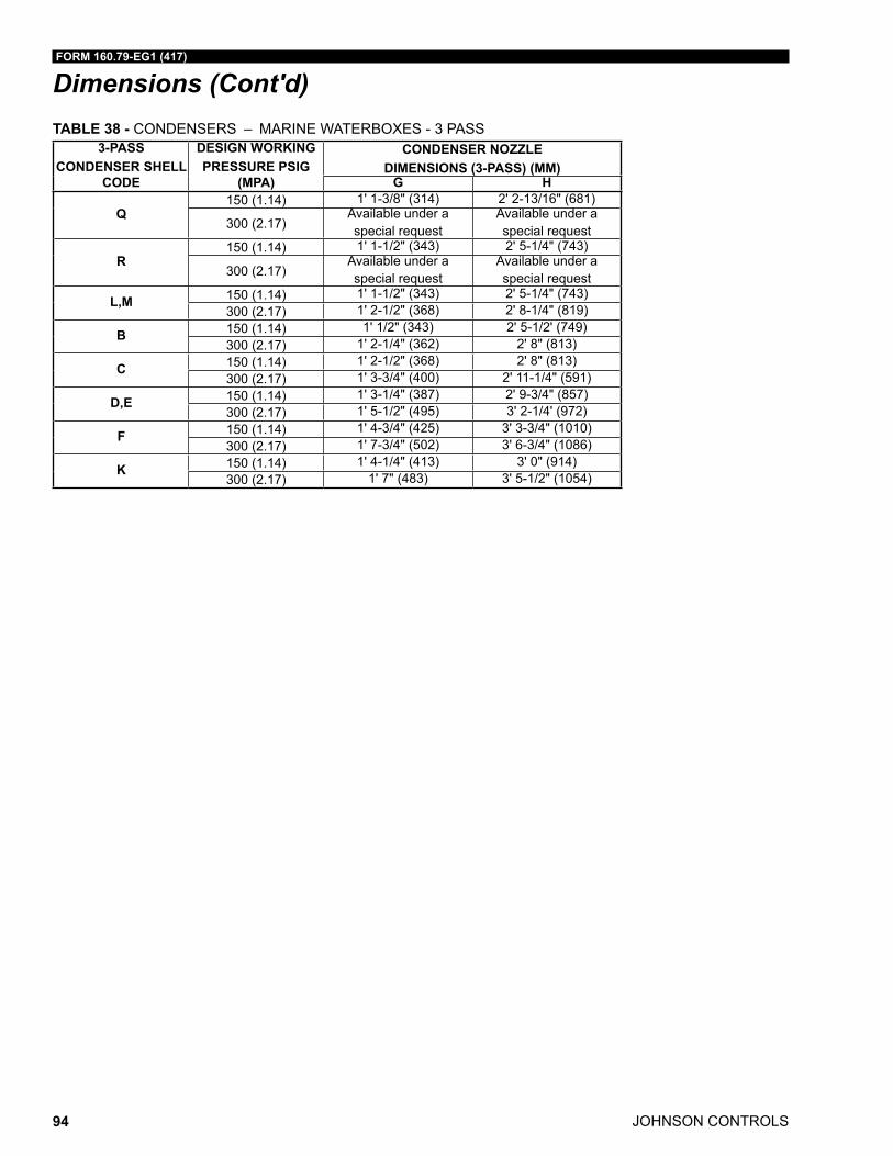
JOHNSON CONTROLS
FORM 160.79-EG1 (417)
94
Dimensions (Cont'd)TABLE 38 - CONDENSERS – MARINE WATERBOXES - 3 PASS
3-PASSCONDENSER SHELL
CODE
DESIGN WORKING PRESSURE PSIG
(MPA)
CONDENSER NOZZLE DIMENSIONS (3-PASS) (MM)
G H
Q150 (1.14) 1' 1-3/8" (314) 2' 2-13/16" (681)
300 (2.17)Available under a special request
Available under a special request
R150 (1.14) 1' 1-1/2" (343) 2' 5-1/4" (743)
300 (2.17)Available under a special request
Available under a special request
L,M 150 (1.14) 1' 1-1/2" (343) 2' 5-1/4" (743)300 (2.17) 1' 2-1/2" (368) 2' 8-1/4" (819)
B 150 (1.14) 1' 1/2" (343) 2' 5-1/2' (749)300 (2.17) 1' 2-1/4" (362) 2' 8" (813)
C 150 (1.14) 1' 2-1/2" (368) 2' 8" (813)300 (2.17) 1' 3-3/4" (400) 2' 11-1/4" (591)
D,E 150 (1.14) 1' 3-1/4" (387) 2' 9-3/4" (857)300 (2.17) 1' 5-1/2" (495) 3' 2-1/4' (972)
F 150 (1.14) 1' 4-3/4" (425) 3' 3-3/4" (1010)300 (2.17) 1' 7-3/4" (502) 3' 6-3/4" (1086)
K 150 (1.14) 1' 4-1/4" (413) 3' 0" (914)300 (2.17) 1' 7" (483) 3' 5-1/2" (1054)
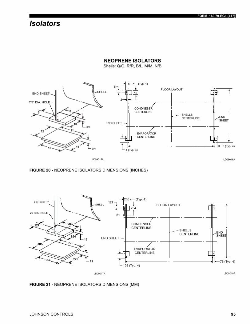
FORM 160.79-EG1 (417)
JOHNSON CONTROLS 95
Isolators
NEOPRENE ISOLATORSShells: Q/Q. R/R, B/L, M/M, N/B
LD09015A
FIGURE 20 - NEOPRENE ISOLATORS DIMENSIONS (INCHES)
END SHEET
7/8” DIA. HOLE
SHELL
2
58
10
3 (Typ. 4)4 (Typ. 4)
*
(Typ. 4)
END SHEET
CONDNESER CENTERLINE
SHELLSCENTERLINE
EVAPORATORCENTERLINE
END SHEET
FLOOR LAYOUT
*
LD09016A
279
254
279
279
LD09017A
FIGURE 21 - NEOPRENE ISOLATORS DIMENSIONS (MM)
FLOOR LAYOUT
END SHEET
EVAPORATOR CENTERLINE
102 (Typ. 4)
CONDENSERCENTERLINE
127
51
203
254
(Typ. 4)
END SHEET
SHELLS CENTERLINE
*
* 76 (Typ. 4)
LD09018A
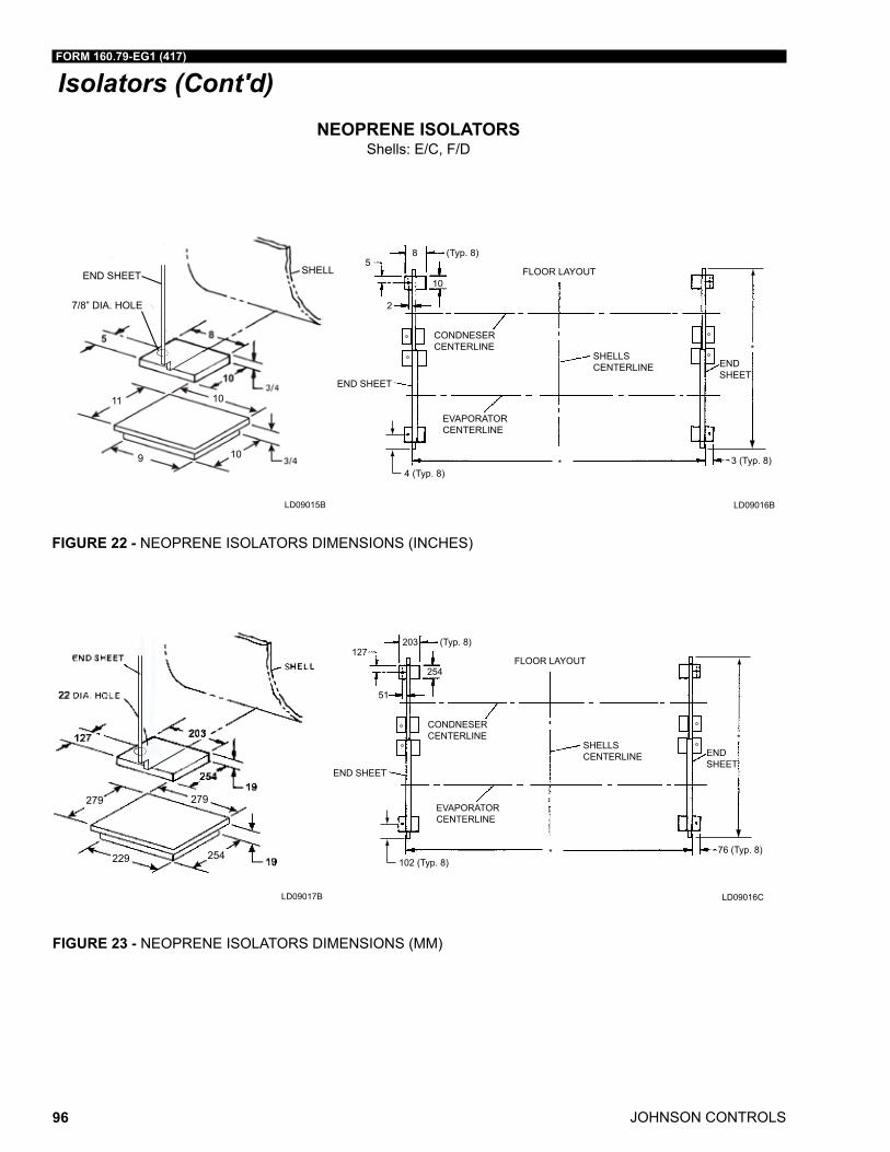
JOHNSON CONTROLS
FORM 160.79-EG1 (417)
96
Isolators (Cont'd)NEOPRENE ISOLATORS
Shells: E/C, F/D
FIGURE 22 - NEOPRENE ISOLATORS DIMENSIONS (INCHES)
2
58
10
3 (Typ. 8)4 (Typ. 8)
*
(Typ. 8)
END SHEET
CONDNESER CENTERLINE
SHELLSCENTERLINE
EVAPORATORCENTERLINE
END SHEET
FLOOR LAYOUT
*
END SHEET
7/8” DIA. HOLE
SHELL
11 10
109
LD09016BLD09015B
FIGURE 23 - NEOPRENE ISOLATORS DIMENSIONS (MM)
279
229
279
254
279
51
127203
254
76 (Typ. 8)102 (Typ. 8)
*
(Typ. 8)
END SHEET
CONDNESER CENTERLINE
SHELLSCENTERLINE
EVAPORATORCENTERLINE
END SHEET
FLOOR LAYOUT
*
LD09016CLD09017B
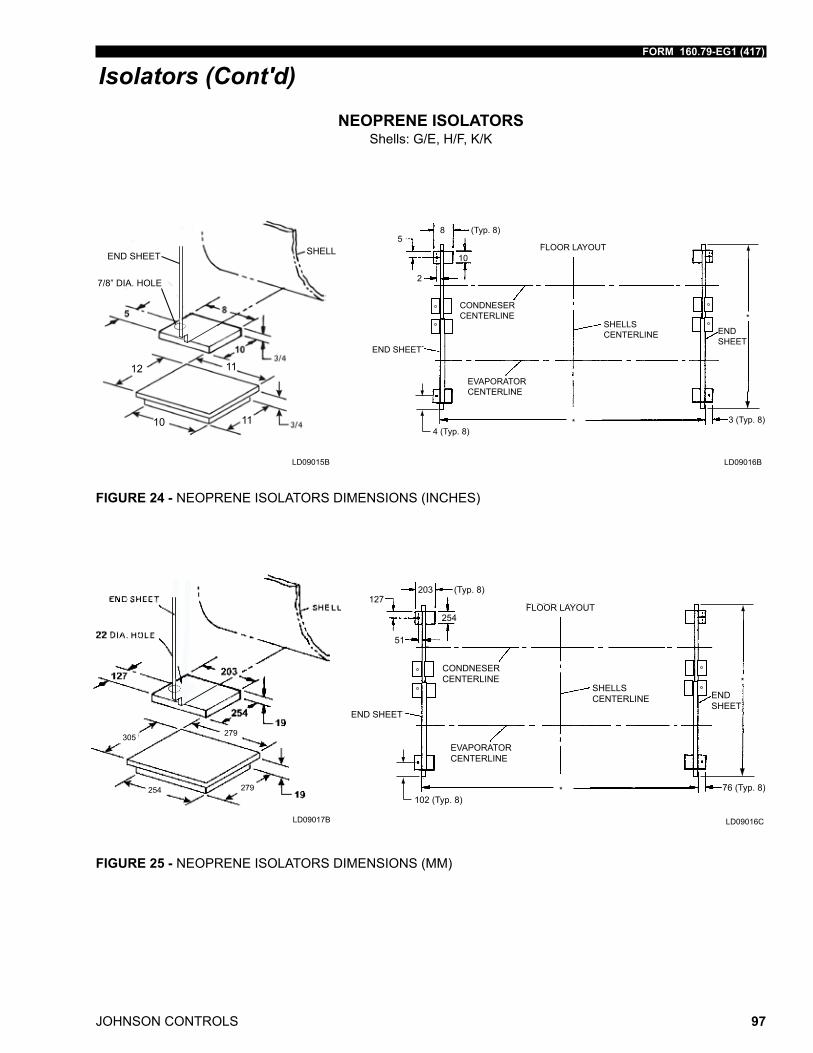
FORM 160.79-EG1 (417)
JOHNSON CONTROLS 97
Isolators (Cont'd)
NEOPRENE ISOLATORSShells: G/E, H/F, K/K
FIGURE 24 - NEOPRENE ISOLATORS DIMENSIONS (INCHES)
2
58
10
3 (Typ. 8)4 (Typ. 8)
*
(Typ. 8)
END SHEET
CONDNESER CENTERLINE
SHELLSCENTERLINE
EVAPORATORCENTERLINE
END SHEET
FLOOR LAYOUT
*
END SHEET
7/8” DIA. HOLE
SHELL
11 10
109
12
10
11
11
LD09015B LD09016B
FIGURE 25 - NEOPRENE ISOLATORS DIMENSIONS (MM)
279
229
279
254
279
51
127203
254
76 (Typ. 8)102 (Typ. 8)
*
(Typ. 8)
END SHEET
CONDNESER CENTERLINE
SHELLSCENTERLINE
EVAPORATORCENTERLINE
END SHEET
FLOOR LAYOUT
*
305
254 279
279
LD09017B LD09016C
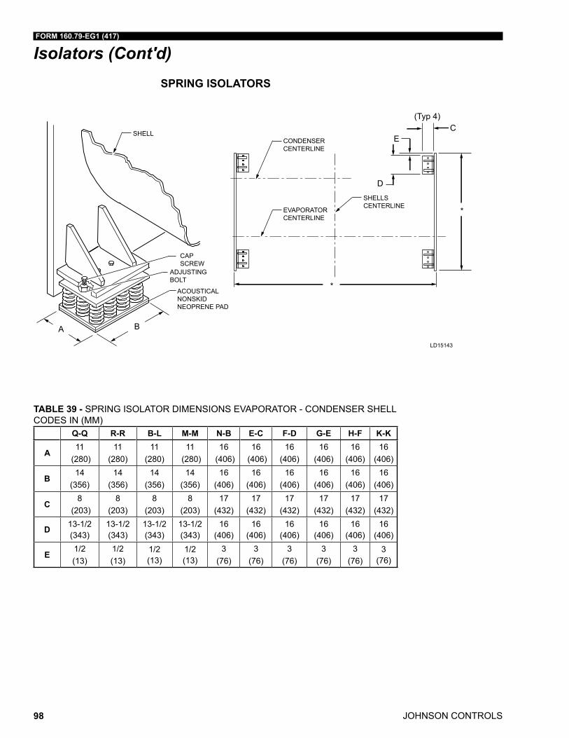
JOHNSON CONTROLS
FORM 160.79-EG1 (417)
98
Isolators (Cont'd)SPRING ISOLATORS
Q-Q R-R B-L M-M N-B E-C F-D G-E H-F K-K
A11
(280)11
(280)11
(280)11
(280)16
(406)16
(406)16
(406)16
(406)16
(406)16
(406)
B14
(356)14
(356)14
(356)14
(356)16
(406)16
(406)16
(406)16
(406)16
(406)16
(406)
C8
(203)8
(203)8
(203)8
(203)17
(432)17
(432)17
(432)17
(432)17
(432)17
(432)
D 13-1/2 (343)
13-1/2 (343)
13-1/2 (343)
13-1/2 (343)
16 (406)
16 (406)
16 (406)
16 (406)
16 (406)
16 (406)
E1/2 (13)
1/2 (13)
1/2 (13)
1/2 (13)
3 (76)
3 (76)
3 (76)
3 (76)
3 (76)
3 (76)
CONDENSERCENTERLINE
SHELL
EVAPORATORCENTERLINE
CAP SCREW
ADJUSTING BOLT
SHELLSCENTERLINE
*
D
CE
*ACOUSTICAL NONSKIDNEOPRENE PAD
A B
(Typ 4)
LD15143
TABLE 39 - SPRING ISOLATOR DIMENSIONS EVAPORATOR - CONDENSER SHELL CODES IN (MM)
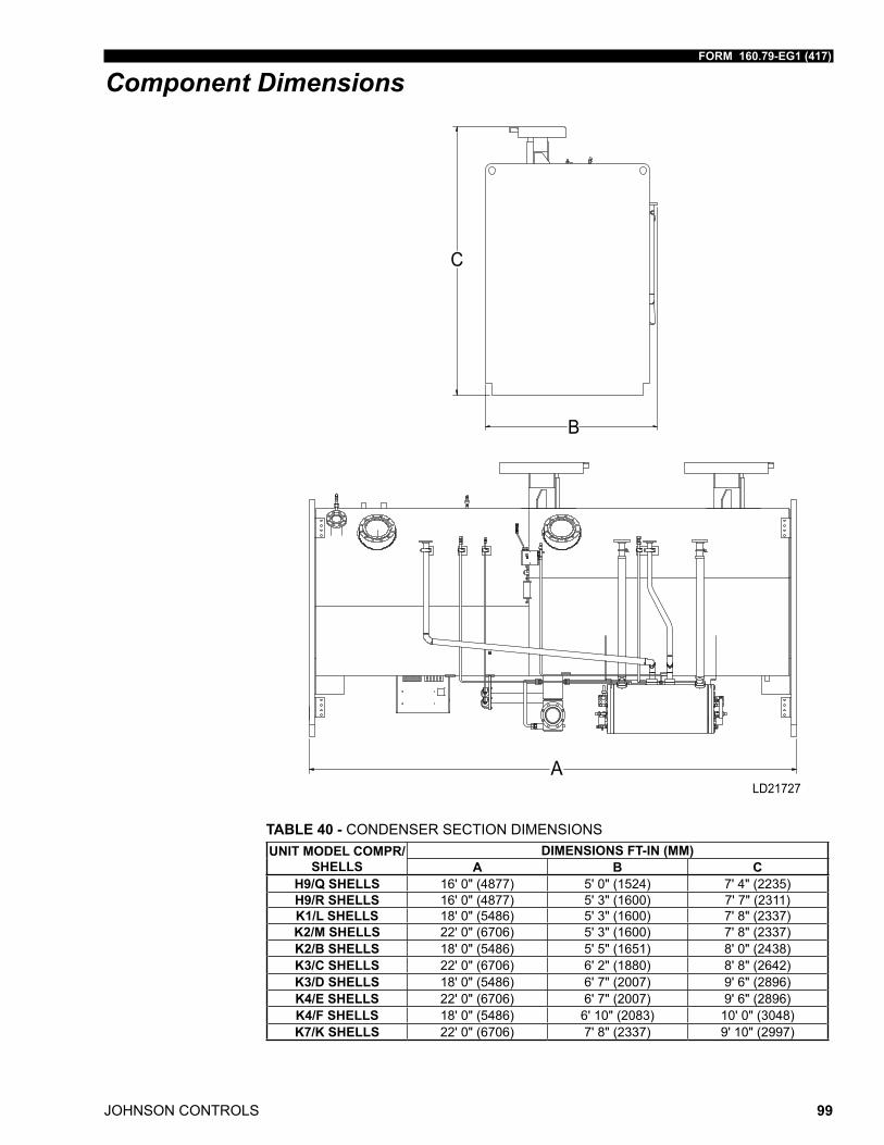
FORM 160.79-EG1 (417)
JOHNSON CONTROLS 99
Component Dimensions
TABLE 40 - CONDENSER SECTION DIMENSIONSUNIT MODEL COMPR/
SHELLSDIMENSIONS FT-IN (MM)
A B CH9/Q SHELLS 16' 0" (4877) 5' 0" (1524) 7' 4" (2235)H9/R SHELLS 16' 0" (4877) 5' 3" (1600) 7' 7" (2311)K1/L SHELLS 18' 0" (5486) 5' 3" (1600) 7' 8" (2337)K2/M SHELLS 22' 0" (6706) 5' 3" (1600) 7' 8" (2337)K2/B SHELLS 18' 0" (5486) 5' 5" (1651) 8' 0" (2438)K3/C SHELLS 22' 0" (6706) 6' 2" (1880) 8' 8" (2642)K3/D SHELLS 18' 0" (5486) 6' 7" (2007) 9' 6" (2896)K4/E SHELLS 22' 0" (6706) 6' 7" (2007) 9' 6" (2896)K4/F SHELLS 18' 0" (5486) 6' 10" (2083) 10' 0" (3048)K7/K SHELLS 22' 0" (6706) 7' 8" (2337) 9' 10" (2997)
C
B
ALD21727
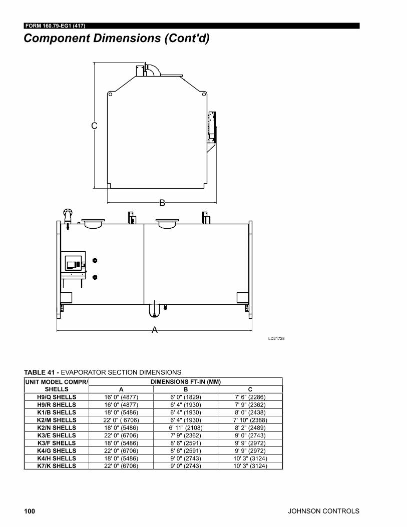
JOHNSON CONTROLS
FORM 160.79-EG1 (417)
100
Component Dimensions (Cont'd)
TABLE 41 - EVAPORATOR SECTION DIMENSIONS UNIT MODEL COMPR/
SHELLSDIMENSIONS FT-IN (MM)
A B CH9/Q SHELLS 16' 0" (4877) 6' 0" (1829) 7' 6" (2286)H9/R SHELLS 16' 0" (4877) 6' 4" (1930) 7' 9" (2362)K1/B SHELLS 18' 0" (5486) 6' 4" (1930) 8' 0" (2438)K2/M SHELLS 22' 0" ( 6706) 6' 4" (1930) 7' 10" (2388)K2/N SHELLS 18' 0" (5486) 6' 11" (2108) 8' 2" (2489)K3/E SHELLS 22' 0" (6706) 7' 9" (2362) 9' 0" (2743)K3/F SHELLS 18' 0" (5486) 8' 6" (2591) 9' 9" (2972)K4/G SHELLS 22' 0" (6706) 8' 6" (2591) 9' 9" (2972)K4/H SHELLS 18' 0" (5486) 9' 0" (2743) 10' 3" (3124)K7/K SHELLS 22' 0" (6706) 9' 0" (2743) 10' 3" (3124)
LD21728
C
B
ALD21728
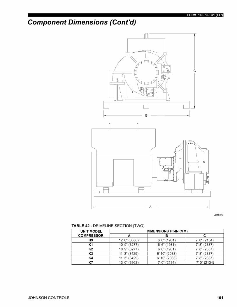
FORM 160.79-EG1 (417)
JOHNSON CONTROLS 101
Component Dimensions (Cont'd)
TABLE 42 - DRIVELINE SECTION (TWO) UNIT MODEL
COMPRESSOR DIMENSIONS FT-IN (MM)
A B CH9 12' 0" (3658) 6' 6" (1981) 7' 0" (2134)K1 10’ 9” (3277) 6’ 6” (1981) 7’ 8” (2337)K2 10’ 9” (3277) 6’ 6” (1981) 7’ 8” (2337)K3 11’ 3” (3429) 6’ 10” (2083) 7’ 8” (2337)K4 11’ 3” (3429) 6’ 10” (2083) 7’ 8” (2337)K7 13’ 0” (3962) 7’ 0” (2134) 7’ 0” (2134)
LD18379
A
B
C
LD18379
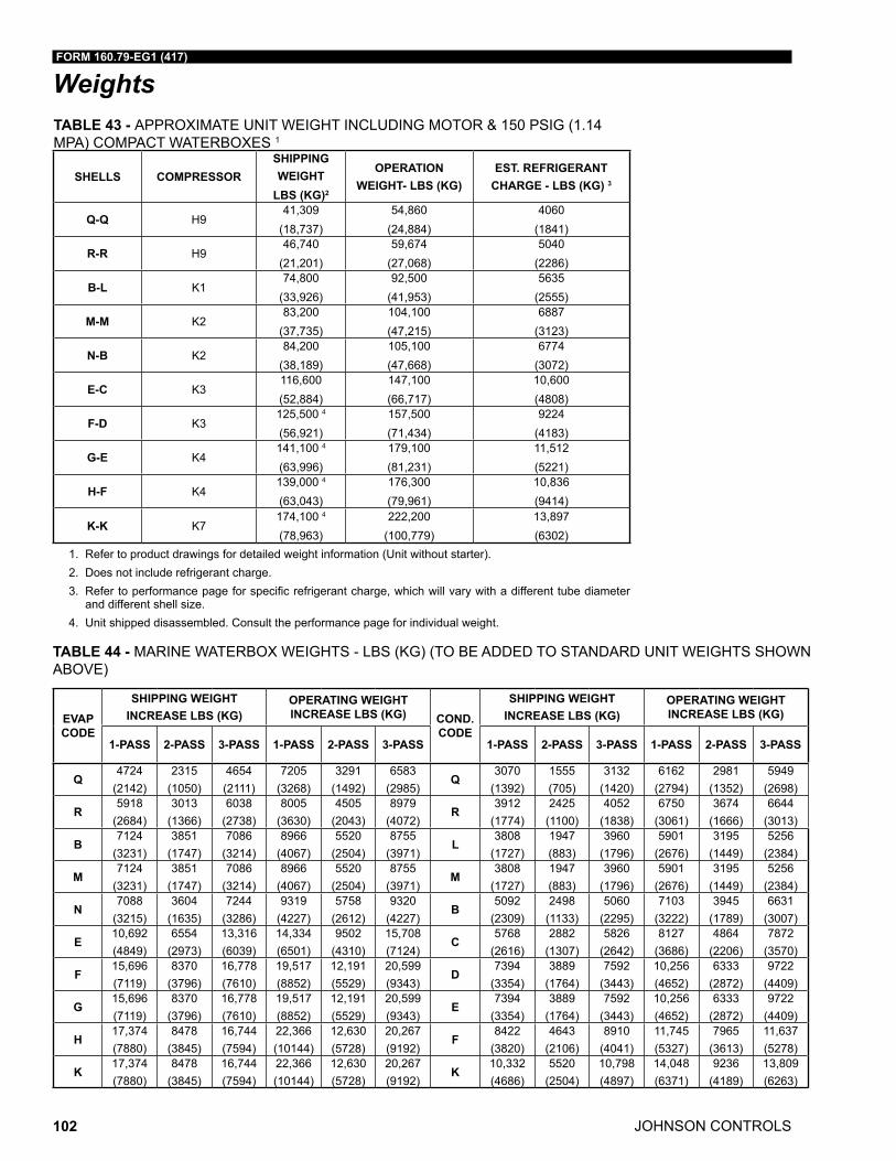
JOHNSON CONTROLS
FORM 160.79-EG1 (417)
102
WeightsTABLE 43 - APPROXIMATE UNIT WEIGHT INCLUDING MOTOR & 150 PSIG (1.14 MPA) COMPACT WATERBOXES 1
SHELLS COMPRESSORSHIPPING WEIGHT
LBS (KG)2
OPERATION WEIGHT- LBS (KG)
EST. REFRIGERANT CHARGE - LBS (KG) 3
Q-Q H941,309
(18,737)54,860
(24,884)4060
(1841)
R-R H946,740
(21,201)59,674
(27,068)5040
(2286)
B-L K174,800
(33,926)92,500
(41,953)5635
(2555)
M-M K283,200
(37,735)104,100(47,215)
6887(3123)
N-B K284,200
(38,189)105,100(47,668)
6774(3072)
E-C K3116,600(52,884)
147,100(66,717)
10,600(4808)
F-D K3125,500 4
(56,921)157,500(71,434)
9224(4183)
G-E K4141,100 4
(63,996)179,100(81,231)
11,512(5221)
H-F K4139,000 4
(63,043)176,300(79,961)
10,836(9414)
K-K K7174,100 4
(78,963)222,200
(100,779)13,897(6302)
1. Refer to product drawings for detailed weight information (Unit without starter). 2. Does not include refrigerant charge.3. Refertoperformancepageforspecificrefrigerantcharge,whichwillvarywithadifferenttubediameter
and different shell size.4. Unit shipped disassembled. Consult the performance page for individual weight.
TABLE 44 - MARINE WATERBOX WEIGHTS - LBS (KG) (TO BE ADDED TO STANDARD UNIT WEIGHTS SHOWN ABOVE)
EVAP CODE
SHIPPING WEIGHT INCREASE LBS (KG)
OPERATING WEIGHT INCREASE LBS (KG) COND.
CODE
SHIPPING WEIGHT INCREASE LBS (KG)
OPERATING WEIGHT INCREASE LBS (KG)
1-PASS 2-PASS 3-PASS 1-PASS 2-PASS 3-PASS 1-PASS 2-PASS 3-PASS 1-PASS 2-PASS 3-PASS
Q4724
(2142)2315
(1050)4654 (2111)
7205 (3268)
3291 (1492)
6583 (2985)
Q3070
(1392)1555 (705)
3132 (1420)
6162 (2794)
2981 (1352)
5949 (2698)
R5918
(2684)3013
(1366)6038
(2738)8005
(3630)4505
(2043)8979
(4072)R
3912 (1774)
2425 (1100)
4052 (1838)
6750 (3061)
3674 (1666)
6644 (3013)
B7124
(3231)3851
(1747)7086
(3214)8966
(4067)5520
(2504)8755
(3971)L
3808 (1727)
1947 (883)
3960 (1796)
5901 (2676)
3195 (1449)
5256 (2384)
M7124
(3231)3851
(1747)7086
(3214)8966
(4067)5520
(2504)8755
(3971)M
3808 (1727)
1947 (883)
3960 (1796)
5901 (2676)
3195 (1449)
5256 (2384)
N7088
(3215)3604
(1635)7244
(3286)9319
(4227)5758
(2612)9320
(4227)B
5092 (2309)
2498 (1133)
5060 (2295)
7103 (3222)
3945 (1789)
6631 (3007)
E 10,692 (4849)
6554 (2973)
13,316 (6039)
14,334 (6501)
9502 (4310)
15,708 (7124)
C 5768
(2616)2882
(1307)5826
(2642)8127
(3686)4864
(2206)7872
(3570)
F15,696 (7119)
8370 (3796)
16,778 (7610)
19,517 (8852)
12,191 (5529)
20,599 (9343)
D7394
(3354)3889
(1764)7592
(3443)10,256 (4652)
6333 (2872)
9722 (4409)
G15,696 (7119)
8370 (3796)
16,778 (7610)
19,517 (8852)
12,191 (5529)
20,599 (9343)
E7394
(3354)3889
(1764)7592
(3443)10,256 (4652)
6333 (2872)
9722 (4409)
H17,374 (7880)
8478 (3845)
16,744 (7594)
22,366 (10144)
12,630 (5728)
20,267 (9192)
F8422
(3820)4643
(2106)8910
(4041)11,745 (5327)
7965 (3613)
11,637 (5278)
K17,374 (7880)
8478 (3845)
16,744 (7594)
22,366 (10144)
12,630 (5728)
20,267 (9192)
K10,332 (4686)
5520 (2504)
10,798 (4897)
14,048 (6371)
9236 (4189)
13,809 (6263)
FORM 160.79-EG1 (417)
JOHNSON CONTROLS 103
Guide Specifications
GENERAL
Furnish and install where indicated on the drawings ____ a dual centrifugal compressor liquid chilling Unit(s). Each unit shall produce a capacity of ____tons (kW), cooling_____GPM (L/s) of ____ from _____°F (°C) to _____°F (°C) when supplied with _____ GPM of condenser water at ______°F (°C). Total power input (two motors) shall not exceed ______ kW with an IPLV (NPLV) of _____. The evaporator shall be selected for _____fouling factor and a maximum liquid pressure drop of _____ft (m). Water side shall be designed for 150 psig (1.14 MPa) working pressure. The condenser shall be selected for______fouling factor and maximum liquid pressure drop of ______ft. Waterside shall be designed for 150 psig (1.14 MPa) working pressure.
Low voltage units:
Power shall be supplied to the compressor drive motors at ______volts – 3 phase – (60) (50) Hertz.
Medium voltage units:
Power shall be supplied to the compressor drive motors at ______volts – 3 phase – (60) (50) Hertz. Auxiliary power to the oil pump motors shall be supplied at ______ volts – 3 phase – (60) (50) Hertz and controls shall be supplied at 115 volts – 1 phase – (60) (50) Hertz.
Units with unit mounted starters shall not require additional auxiliary power supply for oil pump power and controls, which is factory wired from the unit mounted starter.
Performance shall be rated in accordance with the latest edition of AHRI Standard 550/590 as applicable.
Each unit shall be completely factory packaged including evaporator, condenser, sub cooler, compressors, open motors, lubrication system, Control Center, and all intercon-necting unit piping and wiring. The chiller shall be painted prior to shipment. Larger (K3 to K7 compressor) size chillers shall be shipped disassembled, with the drivelines removed and skidded and the evaporator and condenser split. The initial charge of oil and refriger-ant shall be supplied, shipped in containers and cylinders for field installation in the chiller.
COMPRESSORS
Two centrifugal compressors shall be provided, operating in parallel and utilizing a com-mon refrigerant circuit on the chiller. An electrically operated tight closing butterfly valve shall be furnished in the discharge of each compressor, to allow either compressor to be turned off at low chiller loads.
Each compressor shall be a single stage centrifugal type, powered by an open-drive electric motor. The housing shall be fully accessible with vertical circular joints, with the complete operating assembly removable from the compressor and scroll housing. Com-pressor castings shall be designed for a minimum 235 psig (1.72 MPa) working pressure and hydrostatically pressure tested at a minimum of 352 psig (2.53 MPa). The rotor as-sembly shall consist of a heat treated alloy steel drive shaft and impeller shaft with a cast
JOHNSON CONTROLS
FORM 160.79-EG1 (417)
104
Guide Specifications (Cont'd)aluminum, fully shrouded impeller. The impeller shall be designed for balanced thrust, dynamically balanced and overspeed tested for smooth, vibration free operation. Insert type journal and thrust bear-ings shall be fabricated of aluminum alloy, precision bored and axially grooved.
Internal single helical gears with crowned teeth shall be designed so that more than one tooth is in contact at all times to provide even load distribution and quiet operation. Each gear shall be individually mounted in its own journal and thrust bearings to isolate it from impeller and motor forces. Shaft seal shall be provided in double bellows, double seal and cartridge type. A gravity fed oil reservoir shall be built into the top of the compressor to provide lubrication during coast down in the event of a power failure.
Capacity control shall be achieved by use of pre-rotation vanes to provide fully modulat-ing control from full load to minimum load. Control shall automatically compensate for adverse operating conditions, such as fouled tubes, and adjust to prior operation after correction of these conditions.
The unit shall be capable of continuous, reliable operation with low entering condenser fluid temperature at all load conditions as outlined on the equipment schedule. An external electric actuator shall automatically control pre rotation vane position for each compres-sor.
LUBRICATION SYSTEM
Lubrication oil shall be force fed to all compressor bearings, gears, and rotating surfaces by variable speed oil pumps mounted in a common pump housing or oil reservoir. Each oil pump shall vary oil flow to its compressor based on operating and stand by conditions, ensuring adequate lubrication at all times. The oil pump shall operate prior to start up, dur-ing compressor operation and during coast down. Each compressor shall have an internal auxiliary reservoir to provide lubrication during coast down in the event of a power failure.
A common oil reservoir mounted below the dual centrifugal compressors shall contain a 2 HP submersible oil pump for each compressor. Each oil pump shall be built into a remov-able cover, one at each end of the reservoir. The oil reservoir shall be UL listed and shall be factory air strength tested at 1.1 times design working pressure.
Two 2kW immersion oil heaters shall be provided, one in each pump cover. The heaters shall be thermostatically controlled to remove refrigerant from the oil.
Oil cooling shall be done via a refrigerant cooled oil cooler at the discharge of each oil pump. A thermostatically controlled expansion valve shall maintain the required oil tem-perature supply from each oil cooler to its compressor. Oil shall be filtered by externally mounted ½ micron replaceable cartridge oil filters, equipped with service valves. An auto-matic oil return system to recover any oil that may have migrated to the evaporator shall be provided. Oil piping shall be completely factory installed and tested.
MOTOR DRIVELINE
Each compressor motor shall be an open drip proof, squirrel cage, induction type operat-ing at 3570 rpm (2975 rpm for 50 Hz operation).
Each open motor shall be provided with a D flange, bolted to a cast iron adaptor mounted on the compressor to allow the motor to be rigidly coupled to the compressor to provide factory alignment of motor and compressor shafts. Each Motor drive shaft shall be directly connected to its compressor shaft with a flexible disc coupling. The coupling shall have all metal construction with no wearing parts to assure long life, and no lubrication require-ments to provide low maintenance. For units utilizing remote starters or drives, a large
FORM 160.79-EG1 (417)
JOHNSON CONTROLS 105
Guide Specifications (Cont'd)steel terminal box with gasketed front access cover shall be provided for field connected conduit. Overload/overcurrent transformers shall be furnished with all units.
EVAPORATOR
Evaporator shall be of the shell and tube, flooded type designed for a minimum of 180 psig (1.34 MPa) working pressure on the refrigerant side. Shell shall be fabricated from rolled carbon steel plates with fusion welded seams, carbon steel tube sheets, drilled and reamed to accommodate the tubes, and intermediate tube supports spaced no more than four feet apart. The refrigerant side of each shell is designed, tested and stamped in accordance with ASME Boiler and Pressure Vessel Code, Section VIII – Division I, or other pressure vessel code as appropriate. Heat exchanger tubes shall be high efficiency, externally and internally enhanced type. Tubes shall utilize the “skip fin” design, providing a smooth internal and external surface at each intermediate tube support. This provides extra wall thickness and non work-hardened copper at the support location, extending the life of the heat exchangers. If skip fin tubes are not used, minimum tube wall thickness shall be 0.035” (0.9 mm). Each tube shall be roller expanded into the tube sheets provid-ing a leak proof seal, and be individually replaceable. Water velocity through the tubes shall not exceed 12 ft./sec. (3.65 m/sec). A liquid level sight glass shall be provided on the side of the shell to aid in determining proper refrigerant charge and to check condition of the refrigerant charge. Aluminum mesh eliminators shall be located above the tube bundle to prevent liquid refrigerant carryover to the compressor. The evaporator shall have a re-frigerant relief device sized to meet the requirements of the ASHRAE 15 Safety Code for Mechanical Refrigeration.
Waterboxes shall be removable to permit tube cleaning and replacement. Stub out water connections having ANSI/AWWA C 606 couplings grooves shall be provided. Waterboxes shall be designed for 150 psig (1.14 MPa) design working pressure and be tested at 225 psig (1.65 MPa). Vent and drain connections with plugs shall be provided on each water-box. Low flow protection shall be provided by a thermal type flow sensor, factory mounted in the water nozzle connection and wired to the chiller panel.
CONDENSER
Condenser shall be of the shell and tube type, designed for a minimum of 235 psig (1.72 MPa) working pressure on the refrigerant side. Shell shall be fabricated from rolled carbon steel plates with fusion welded seams. Carbon steel tube sheets, drilled and reamed to accommodate the tubes, are welded to the end of each shell. Intermediate tube supports are drilled and reamed to eliminate sharp edges, fabricated from carbon steel plates. The refrigerant side of each shell is designed, tested and stamped in accordance with ASME Boiler and Pressure Vessel Code, Section VIII – Division I, or other pressure vessel code as appropriate.
Heat exchanger tubes shall be high efficiency, externally and internally enhanced type. Tubes shall utilize the “skip fin” design, providing a smooth internal and external surface at each intermediate tube support. This provides extra wall thickness and non work hard-ened copper at the support location, extending the life of the heat exchangers. If skip fin tubes are not used, minimum tube wall thickness shall be 0.035” (0.9 mm). Each tube shall be roller expanded into the tube sheets providing a leak proof seal, and be individu-ally replaceable. Water velocity through the tubes shall not exceed 12 ft./sec. (3.65 m/ sec.). A liquid level sight glass shall be provided on the side of the shell to aid in determin-ing proper refrigerant charge and to check condition of the refrigerant charge. The con-denser shall have dual refrigerant relief devices; each sized to meet the requirements of the ASHRAE 15 Safety Code for Mechanical Refrigeration. Arrangement shall allow either valve to be isolated and replaced without removing the unit refrigerant charge.
JOHNSON CONTROLS
FORM 160.79-EG1 (417)
106
Guide Specifications (Cont'd)The condenser shall be provided with positive shutoff valves in each compressor dis-charge line to the condenser. Additional tight closing valves shall be included in the liquid line leaving the condenser and the refrigerant liquid line to the oil coolers. This will allow pump down and storage of the refrigerant charge in the condenser. Due to the possibility of not seating properly, check valves are not acceptable for isolation purposes. If a check valve is used, a positive shutoff valve must be provided in series with the check valve.
Waterboxes shall be removable to permit tube cleaning and replacement. Stub out water connections having ANSI/AWWA C 606 couplings grooves shall be provided. Waterboxes shall be designed for 150 psig (1.14 MPa) design working pressure and be tested at 225 psig (1.65 MPa). Vent and drain connections with plugs shall be provided on each water-box. Low flow protection shall be provided by a thermal type water flow sensor, factory mounted in the water nozzle connection and wired to the chiller control panel.
REFRIGERANT FLOW CONTROL
Refrigerant flow to the evaporator shall be controlled by a variable orifice control valve. The variable orifice control shall automatically adjust to maintain proper refrigerant level in the condenser and evaporator. This shall be controlled by monitoring refrigerant liquid level in the condenser, assuring optimal subcooler performance.
CONTROL CENTER
General – The chiller shall be controlled by a single microprocessor based control center. The chiller control panel shall provide control of chiller operation and monitoring of chiller sensors, actuators, relays and switches. The chiller panel shall provide capacity control operation of the two parallel compressors, and shall provide cycling of compressors in response to load requirements.
Control Panel – The control panel shall include a 10.4" (265 mm). diagonal color liquid crystal display (LCD) surrounded by "soft" keys which are redefined based on the screen displayed at that time. This shall be mounted in the middle of a keypad interface and installed in a locked enclosure. The screen shall detail all operations and parameters, using a graphical representation of the chiller and its major components. Panel verbiage shall be available in other languages as an option, with English always available. Data shall be displayed in either English or Metric units. Smart Freeze Point Protection shall run the chiller at 36°F (2.2°C) leaving chilled water temperature, and not have nuisance trips on low water temperature. The sophisticated program and sensor shall monitor the chiller water temperature to prevent freeze up. The panel shall display countdown timer messages so the operator knows when functions are starting and stopping. Every pro-grammable point shall have a pop up screen with the allowable ranges, so that the chiller cannot be programmed to operate outside of its design limits.
The chiller control panel shall also provide:
A. System operating information including:
• Return and leaving chilled water temperature
• Return and leaving condenser water temperature
• Evaporator and condenser saturation temperature
• Differential oil pressure (both compressors)
• Percent motor current (both motors)
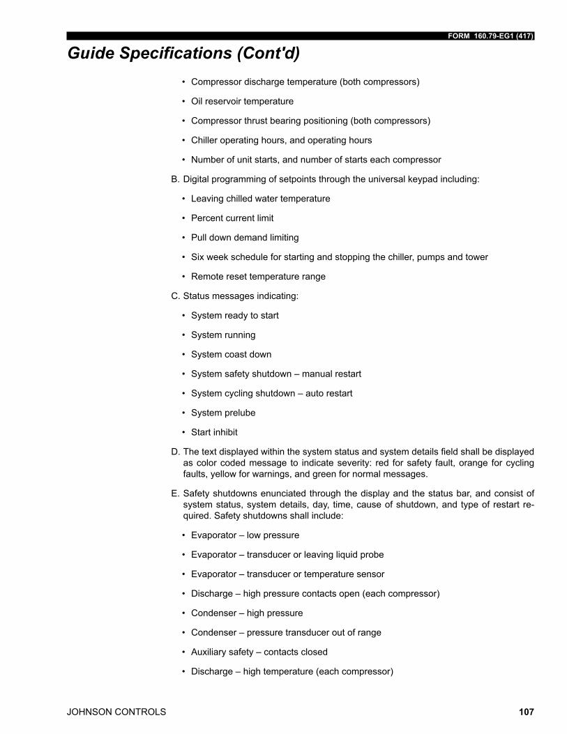
FORM 160.79-EG1 (417)
JOHNSON CONTROLS 107
Guide Specifications (Cont'd)• Compressor discharge temperature (both compressors)
• Oil reservoir temperature
• Compressor thrust bearing positioning (both compressors)
• Chiller operating hours, and operating hours
• Number of unit starts, and number of starts each compressor
B. Digital programming of setpoints through the universal keypad including:
• Leaving chilled water temperature
• Percent current limit
• Pull down demand limiting
• Six week schedule for starting and stopping the chiller, pumps and tower
• Remote reset temperature range
C. Status messages indicating:
• System ready to start
• System running
• System coast down
• System safety shutdown – manual restart
• System cycling shutdown – auto restart
• System prelube
• Start inhibit
D. Thetextdisplayedwithinthesystemstatusandsystemdetailsfieldshallbedisplayedas color coded message to indicate severity: red for safety fault, orange for cycling faults, yellow for warnings, and green for normal messages.
E. Safety shutdowns enunciated through the display and the status bar, and consist of system status, system details, day, time, cause of shutdown, and type of restart re-quired. Safety shutdowns shall include:
• Evaporator – low pressure
• Evaporator – transducer or leaving liquid probe
• Evaporator – transducer or temperature sensor
• Discharge – high pressure contacts open (each compressor)
• Condenser – high pressure
• Condenser – pressure transducer out of range
• Auxiliary safety – contacts closed
• Discharge – high temperature (each compressor)
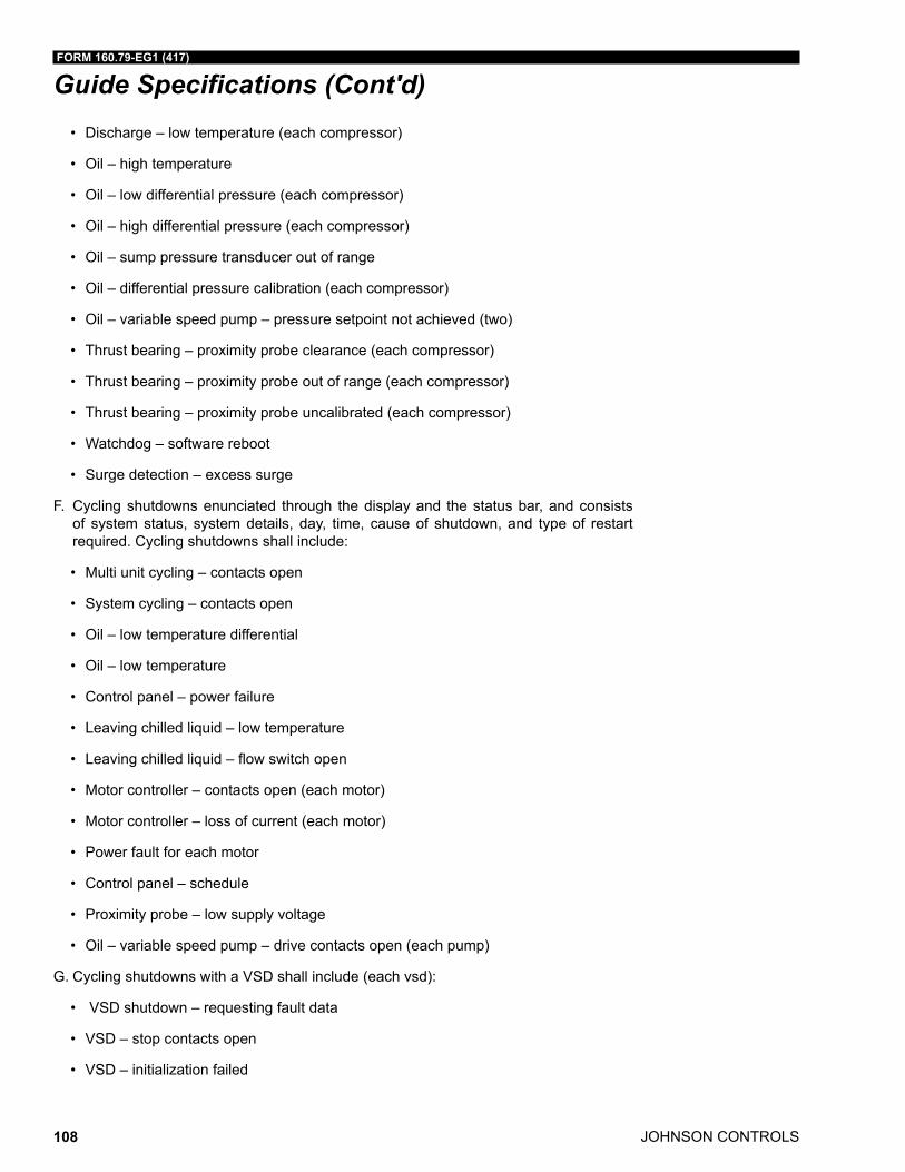
JOHNSON CONTROLS
FORM 160.79-EG1 (417)
108
Guide Specifications (Cont'd)• Discharge – low temperature (each compressor)
• Oil – high temperature
• Oil – low differential pressure (each compressor)
• Oil – high differential pressure (each compressor)
• Oil – sump pressure transducer out of range
• Oil – differential pressure calibration (each compressor)
• Oil – variable speed pump – pressure setpoint not achieved (two)
• Thrust bearing – proximity probe clearance (each compressor)
• Thrust bearing – proximity probe out of range (each compressor)
• Thrust bearing – proximity probe uncalibrated (each compressor)
• Watchdog – software reboot
• Surge detection – excess surge
F. Cycling shutdowns enunciated through the display and the status bar, and consists of system status, system details, day, time, cause of shutdown, and type of restart required. Cycling shutdowns shall include:
• Multi unit cycling – contacts open
• System cycling – contacts open
• Oil – low temperature differential
• Oil – low temperature
• Control panel – power failure
• Leaving chilled liquid – low temperature
• Leavingchilledliquid–flowswitchopen
• Motor controller – contacts open (each motor)
• Motor controller – loss of current (each motor)
• Power fault for each motor
• Control panel – schedule
• Proximity probe – low supply voltage
• Oil – variable speed pump – drive contacts open (each pump)
G. Cycling shutdowns with a VSD shall include (each vsd):
• VSD shutdown – requesting fault data
• VSD – stop contacts open
• VSD – initialization failed
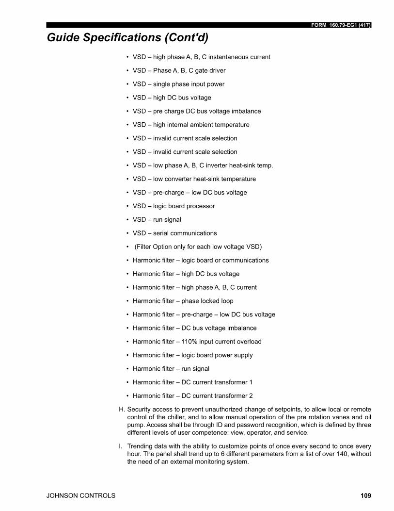
FORM 160.79-EG1 (417)
JOHNSON CONTROLS 109
Guide Specifications (Cont'd)• VSD – high phase A, B, C instantaneous current
• VSD – Phase A, B, C gate driver
• VSD – single phase input power
• VSD – high DC bus voltage
• VSD – pre charge DC bus voltage imbalance
• VSD – high internal ambient temperature
• VSD – invalid current scale selection
• VSD – invalid current scale selection
• VSD – low phase A, B, C inverter heat-sink temp.
• VSD – low converter heat-sink temperature
• VSD – pre-charge – low DC bus voltage
• VSD – logic board processor
• VSD – run signal
• VSD – serial communications
• (Filter Option only for each low voltage VSD)
• Harmonicfilter–logicboardorcommunications
• Harmonicfilter–highDCbusvoltage
• Harmonicfilter–highphaseA,B,Ccurrent
• Harmonicfilter–phaselockedloop
• Harmonicfilter–pre-charge–lowDCbusvoltage
• Harmonicfilter–DCbusvoltageimbalance
• Harmonicfilter–110%inputcurrentoverload
• Harmonicfilter–logicboardpowersupply
• Harmonicfilter–runsignal
• Harmonicfilter–DCcurrenttransformer1
• Harmonicfilter–DCcurrenttransformer2
H. Security access to prevent unauthorized change of setpoints, to allow local or remote control of the chiller, and to allow manual operation of the pre rotation vanes and oil pump.AccessshallbethroughIDandpasswordrecognition,whichisdefinedbythreedifferent levels of user competence: view, operator, and service.
I. Trending data with the ability to customize points of once every second to once every hour. The panel shall trend up to 6 different parameters from a list of over 140, without the need of an external monitoring system.
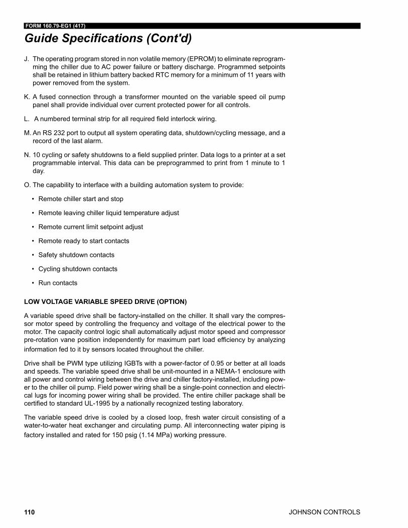
JOHNSON CONTROLS
FORM 160.79-EG1 (417)
110
Guide Specifications (Cont'd)J. The operating program stored in non volatile memory (EPROM) to eliminate reprogram-
ming the chiller due to AC power failure or battery discharge. Programmed setpoints shall be retained in lithium battery backed RTC memory for a minimum of 11 years with power removed from the system.
K. A fused connection through a transformer mounted on the variable speed oil pump panel shall provide individual over current protected power for all controls.
L. Anumberedterminalstripforallrequiredfieldinterlockwiring.
M. An RS 232 port to output all system operating data, shutdown/cycling message, and a record of the last alarm.
N. 10cyclingorsafetyshutdownstoafieldsuppliedprinter.Datalogstoaprinteratasetprogrammable interval. This data can be preprogrammed to print from 1 minute to 1 day.
O. The capability to interface with a building automation system to provide:
• Remote chiller start and stop
• Remote leaving chiller liquid temperature adjust
• Remote current limit setpoint adjust
• Remote ready to start contacts
• Safety shutdown contacts
• Cycling shutdown contacts
• Run contacts
LOW VOLTAGE VARIABLE SPEED DRIVE (OPTION)
A variable speed drive shall be factory-installed on the chiller. It shall vary the compres-sor motor speed by controlling the frequency and voltage of the electrical power to the motor. The capacity control logic shall automatically adjust motor speed and compressor pre-rotation vane position independently for maximum part load efficiency by analyzing information fed to it by sensors located throughout the chiller.
Drive shall be PWM type utilizing IGBTs with a power-factor of 0.95 or better at all loads and speeds. The variable speed drive shall be unit-mounted in a NEMA-1 enclosure with all power and control wiring between the drive and chiller factory-installed, including pow-er to the chiller oil pump. Field power wiring shall be a single-point connection and electri-cal lugs for incoming power wiring shall be provided. The entire chiller package shall be certified to standard UL-1995 by a nationally recognized testing laboratory.
The variable speed drive is cooled by a closed loop, fresh water circuit consisting of a water-to-water heat exchanger and circulating pump. All interconnecting water piping is factory installed and rated for 150 psig (1.14 MPa) working pressure.
FORM 160.79-EG1 (417)
JOHNSON CONTROLS 111
Guide Specifications (Cont'd)The following features shall be provided: a door interlocked circuit breaker, capable of being padlocked; UL listed ground fault protection; overvoltage and under voltage protec-tion; 3-phase sensing motor overcurrent protection; single phase protection; insensitive to phase rotation; over temperature protection; digital readout at the chiller unit control panel of:
• Output Frequency
• Output Voltage
• 3-phase output current
• Input Kilowatts (kW) and Kilowatt-hours (kWH)
• Self diagnostic service parameters
• Separate meters for this information shall not be acceptable.
(Optional) A harmonic filter that limits electrical power supply distortion for the variable speed drive to comply with the guidelines ofI EEE- 519 2014 shall be provided. The filter shall be unit mounted within the same NEMA 1 enclosure and shall be UL listed. The fol-lowing digital readouts shall be provided at the chiller unit control panel as part of the filter package:
• Input kVA
• Total power-factor
• 3-phase input voltage
• 3-phase input current
• 3-phase input voltage total harmonic distortion (THD)
• 3-phase input current total demand distortion (TDD)
• Self diagnostic service parameters
• Separate meters for this information shall not be acceptable.
FACTORY-INSTALLED COMPRESSOR MOTOR STARTER (2300V & 4160V/3/60 HZ OR 3300V/3/50 HZ)
The chiller manufacturer shall furnish a reduced-voltage, Medium Voltage Solid-State Starter, in accordance with the chiller manufacturer’s starter specifications. The starter shall be of modular construction with complete access to all parts. The starter shall be tested and the design starting current and overload settings adjusted at the factory. The starter shall provide, through the use of six in-line (not inside the Delta) silicon controlled rectifiers (2 per phase), a smooth acceleration of the motor without current transitions or transients. The unit shall be a starter dedicated for each driveline.
JOHNSON CONTROLS
FORM 160.79-EG1 (417)
112
Guide Specifications (Cont'd)The following protective devices and convenience items shall be factory mounted and wired to the starter:
• 3-leg sensing electronic overloads – shuts unit down if current exceeds 105% of FLA to protect the motor windings.
• Phase rotation protection circuit – denies start-up when detecting incorrect power wiring phase sequence to the starter which could cause reverse motor rotation and damage the equipment.
• Single-phase failure protection circuit – ensures against motor burnout by shutting the unit down if power loss occurs in any of the incoming lines during start-up.
• High temperature safety protection system – temperature activated switches on heat sinks will shut the unit down if the SCR temperature exceeds acceptable limits.
• 3-phase digital ammeter and digital voltmeter readout via control center – easily crosscheck design current and voltage limitations against supply characteristics.
• Starter mounted load break rated input disconnect switch with interlocked padlock-able handle. Positive disconnecting means shall be visible from outside the enclo-sure, in operator area. All doors shall be interlocked with the disconnecting means.
• Open/Shorted SCR Protection – Failed semiconductor devices are automatically de-tected and reported via the Control Center.
• Power Fault Protection – momentary power interruption protection detects power interruptions within 3 line cycles and interrupts power to the compressor motor within 1 additional line cycle.
• Electrical connections – these tin-plated or copper bus bars provide easy connection to incoming copper power lines.
• Wattmeter – An instantaneous wattmeter tells the customer how much power the chiller is consuming. A kilowatt-hour energy meter is also provided to measure power consumption over a period of time.
• Shut down History – The Medium Voltage Solid-State Starter shall provide the sys-tem control panel with ten histories of previous unit shutdowns initiated by the starter.
In addition, the Starter shall include as standard, the following convenience items already mounted and wired to the starter at the factory:
• Auxiliary control supply transformer – eliminates the need for running separate 115V- 1 ph-50/60 Hz power source wiring to the chiller Control Center.
• Auxiliary Oil Pump supply transformer – eliminates the need for running sepa-rate low voltage 3 phase power source wiring to the chiller Variable Speed Oil Pump Control Panel.
REMOTE ELECTRO-MECHANICAL COMPRESSOR MOTOR STARTER (OPTION)
A remote mounted electro-mechanical starter shall be furnished for each compressor mo-tor. The starter shall be furnished in accordance with the chiller manufacturer’s starter specifications, and as specified elsewhere in these specifications.
FORM 160.79-EG1 (417)
JOHNSON CONTROLS 113
Guide Specifications (Cont'd)HIGH AND MEDIUM VOLTAGE VARIABLE SPEED STARTER (OPTION)
The Variable Speed Drive will be remote floor mounted. It will vary the compressor motor speed by controlling the frequency and voltage of the electrical power to the motor. The capacity control logic shall automatically adjust motor speed and compressor pre-rotation vane position independently for maximum part-load efficiency by analyzing information fed to it by sensors located throughout the chiller.
Definitions
For the purpose of this Specification, the following definitions apply:
• VSD - Variable speed drive is a device that is used to vary the speed of a previously fixedspeedmotor.
• NPC - Neutral Point Clamp is an VSD topology that has the advantage of reducing the high line to neutral voltage that can occur in other traditional drive designs that can reach 2.7 to 3.3 times normal levels.
• PWM - Pulse Width Modulation is a method of controlling power devices to convert voltage levels. PWM is a popular method of control for converting DC voltage to AC voltage.
• IGBT- Insulated Gate Bipolar Transistor is a high speed electrical switching power device.Itisveryefficientrequiringverylowpowerforcontrolcircuits
• HCT - Hall Effect Current Transformer are used for detection of currents over a fre-quency range of DC to high frequency without direct contact or shunts.
• CPT- Control Power Transformer is typically used to power control circuits and relays for the VSD.
• FLA - Full Load Amps.
Components
The VSD shall consist of the following components:
• Incoming Disconnect
• A24pulseinputIsolationTransformerfromhighvoltagesto4160Vwithrectifierthatlimits electrical power supply distortion.
• Frequency Converter/Inverter
• VSD Protective System/Devices
• Outputfilterorreactor(whenrequiredtolimitreflectedvoltage)
• OutputDisconnect(s)orbypass(whenspecifiedonDataSheet)
• Diagnostics and Control Circuits
• Two control power transformers, for the Control Center and for chiller oil pump opera-tion.
JOHNSON CONTROLS
FORM 160.79-EG1 (417)
114
Guide Specifications (Cont'd)Features
The following features will be provided:
• PWM type utilizing IGBT’s with a power factor of 0.95 or better at all loads and speeds.
• Door interlocked circuit breaker capable of being padlocked.
• UL listed ground fault protection.
• Over voltage and under voltage protection.
• 3-phase sensing motor over current protection.
• Single phase protection.
• Insensitive to phase rotation.
• Over temperature protection.
• Digital readout at the chiller unit control panel of output frequency, output voltage, 3-phase output current, input Kilowatts and Kilowatt-hours, self-diagnostic service parameters, Elapsed Time Meter.
• Separate meters for this information will not be acceptable.
General Design and Fabrication
The VSD inverter/chopper shall be of the pulse width modulated (PWM) Neutral Point Clamp (NPC) type. The output devices shall be Insulated Gate Bipolar Transistors (IG-BT’s) with a minimum voltage rating of 3300V. Use of lower rated devices is unacceptable due to the quantity of devices required in the design.
• Allcomponentsandmaterialshallbenewandofthelatestfieldprovendesignandincurrent production. Obsolete components or components scheduled for immediate discontinuation shall not be used.
• The equipment shall be completely factory built, assembled, wired, and tested. When it is necessary to disassemble the units for ease of transportation, adequate materi-alsandinstructionsshallbeprovidedforeasyfieldreassembling.
• For VSD applications where the line voltage is higher than 6600V and the drive uses an input voltage of 6600V or less then any transformer used to reduce the line voltage from greater than 6600V to less than 6600V must have the transformer inef-ficienciesincludedinthechillerenergyanalysis.
• The VSD shall be capable of continuous operation up to altitudes of 5,000 ft (1,500m).
Enclosures and Cooling
The VSD enclosure shall be suitable for installation in an indoor, unclassified area.
All enclosure openings exceeding 0.25 inch (6 mm) in width shall be provided with screens to prevent the entrance of snakes, rodents, etc. The maximum screen mesh opening width shall be 0.25 inch (6 mm).
FORM 160.79-EG1 (417)
JOHNSON CONTROLS 115
Guide Specifications (Cont'd)A “loss of cooling” fault shutdown shall be furnished with this forced cooled equipment. In the event of clogged filters or fan failure, the drive will shut down safely without electronic component failure.
Air filters shall be of a reusable type that can be easily cleaned. All doors or front panels will be fully gasketed. Air exhaust from cooling fans will be at the top of the enclosure away from personnel in front of the equipment.
Fan motors shall be protected by an input circuit breaker. Metal squirrel cage ball bearing 460V three phase fan motors are to be used in the drive design. Plastic muffin fans are not acceptable. As specified on the data sheet, fan power will be obtained from a remote 460V three-phase power or from the primary 2300 / 3300 / 4160V power through a tap on the input transformer.
The maximum noise level of the unit shall not exceed 80 dBA at a distance of 1 meter from the unit and at a height of 1.5 meters from the floor.
Painting
Use Manufacturer’s standard finish.
Operational Controls
All operator controls and adjustments are through the Chiller control center.
The VSD shall include necessary components to protect the VSD and motor against mo-tor overload, internal faults in either the motor or VSD and disturbances in the incoming AC line.
The following conditions shall cause the VSD to be shut down with the output voltage reduced to zero. The failure shall be annunciated on the Chiller control center.
• Cooling fan loss
• Input transformer over temperature
• Heatsink over temperature
• Motor current overload
• Output current imbalance
• High output frequency
• Input phase loss
• DC Link Voltage imbalance
• DC Link Voltage overvoltage
• DC Link Voltage undervoltage
• Ground fault
• Power supply fault
• IGBT gate drive fault
• Communications fault
• Cabinet doors interlock
JOHNSON CONTROLS
FORM 160.79-EG1 (417)
116
Guide Specifications (Cont'd)Input Power Transformer and Rectifier
The VSD shall contain an incoming isolation transformer whose primary voltage shall be as specified on the Data Sheet.
• The transformer shall contain 12 three phase secondary windings that provide the properphaseshiftingtodevelopa24-pulserectificationtoreduceharmoniccurrentsandvoltagesreflectedtotheprimarypowersystem.
• The transformer shall be copper wound and shall have a 428 °F (220°C) insulation system to operate at 239°F (115°C) rise at full load conditions.
• ThetransformerandrectifiershallbeanintegralpartoftheVSDassemblyalongwithprimary disconnect switch, input vacuum contactor and secondary fusing eliminating theneedforseparatecomponentsfieldinstallationorwiring.
• Soft charge of the DC bus capacitors is accomplished by use of an input reactor on the primary of the input transformer. A vacuum contactor rated for drive full load amps will short the reactor after charge is accomplished.
Control Power Transformers
A 115V single phase nominal 2kVA transformer will be supplied for chiller controls.
A 460V three phase 50/60 Hz up to 3kVA transformer will be supplied for chiller oil pump operation.
Operator Panel Displays:
All operator displays are through the Chiller control center.
The following items will be monitored and displayed:
• Output frequency
• Output voltage
• Motor current
• Input voltage
• Input power
• Energy consumption kWH
Power Requirements
The VSD shall be capable of providing rated output for continuous voltage deviations of +10%.
The VSD input short circuit withstand rating shall be 50,000A.
The VSD shall be able to ride through voltage dips down to 10% of minimum, such as those experienced during motor starting.
The VSD 40 second overload current rating shall be set at 105% of rated compressor current.
FORM 160.79-EG1 (417)
JOHNSON CONTROLS 117
Guide Specifications (Cont'd)The VSD shall comply with the requirements of IEEE- 519 2014.
Voltage distortion shall not exceed 3% and current distortion shall not exceed 5% at the input lugs of the VSD over an operating power range of 30% to 100% of rated power with phase voltage imbalance per the 3% specification.
The VSD converter section shall be configured as a 24 pulse or greater to eliminate the need for harmonic filters.
Power Bus
All power bus bars, when part of the standard design and other current carrying parts shall be tin-plated copper for corrosion resistance. Power bus bar joints shall be tin plated.
Bus bars shall be braced to withstand short circuit currents shown on the Data Sheet with a minimum of 50KAIC.
Input and output connections shall be either top or bottom access in the standard design.
Inverter Section Design
The VSD inverter section shall consist of three cells where each cell has two series DC power supplies per phase. Each DC supply is derived from a phase shifted secondary of the input transformer that cancels reflected harmonics back to the power line. The DC power supply is filtered by long lasting oil filled capacitors. Electrolytic capacitors are not permitted.
Each cell has eight 3300V Insulated Gate Bipolar Transistors (IGBT’s) in a single phase bridge connection such that when in combination with the other bridges, a 5 level output voltage is constructed to the motor. A bridge neutral point is jumpered to each of the three cells. This configuration called Neutral Point Clamp (NPC) provides a normal phase to ground level voltages that are superior to other direct PWM or multi-level twelve cell VSD designs that can cause 1.8 to 3.3 times normal line to ground voltage.
Each power device communicates to the microprocessor with fiber optic communications. No other isolation method is allowed.
A high resistance ground detection circuit at the neutral point is used for system shut-downs in the event the load has a ground fault.
Two Hall Effect Current Transformers (HCT) are used for current feedback on the VSD output.
PWM firing pulses will result in an output voltage and current waveform that will result in less than 2% torque ripple over a 20 to 1 speed range on the motor.
Disconnects
The VSD shall include a main disconnect device with an interlocked and padlockable han-dle mechanism. The disconnecting device shall be a medium voltage vacuum contactor with a bolted pressure disconnect switch whose blades are externally visible from outside the enclosure. The disconnect device shall have a momentary withstand rating greater than the available fault current indicated on the Data Sheet.
When multiple doors are supplied, all doors shall be electrically interlocked with the dis-connect device. The interlocks shall include provisions to manually override for test and repair.
JOHNSON CONTROLS
FORM 160.79-EG1 (417)
118
Guide Specifications (Cont'd)Wiring and Terminations
Bus bar with standard four-hole pattern to be supplied for input and output shall be provid-ed for connection of external wiring and shall be conveniently located, clearly numbered, and identified.
Control wire terminal blocks for external wiring terminations shall be compression screw type, designed to accommodate stripped insulation bare wire ends, and shall accept a minimum of two No. 14 AWG wires.
Connection points for inputs and outputs of different voltage levels shall be segregated to reduce possibility of electrical noise. If necessary, this may be accomplished through the use of terminal barriers and covers.
Where wiring is run through sheet metal or any barrier, bushings, grommets or other me-chanical protection around the sheet or barrier opening shall be provided.
All internal wiring shall be terminated with no more than two (2) conductors per terminal block point.
The VSD shall have an internal mechanical ground connection suitable for terminating a stranded copper ground conductor of the same size as the incoming phase conductors. Ground connections shall be near the incoming and outgoing power cable termination points and control wiring connections.
Minimum wire bending space shall meet or exceed the value shown in NEC Table 430 10 (b) for termination of the power cable and shall be documented on Manufacturer’s draw-ings.
Inspection and Testing
Manufacturer’s standard tests shall be performed. Minimum testing shall include:
Power semiconductors shall be thermally cycled and printed circuit boards shall be burned in prior to final assembly into the VSD.
Individual power cells shall undergo a visual inspection, an electrical inspection, and a complete full load test prior to final assembly into the VSD. A test record for each power cell shall be furnished as part of the final data requirements if requested on the data sheets.
Mechanical operation tests shall be performed for each VSD to verify satisfactory opera-tion. These tests shall include checking operating mechanisms and interlock devices.
Electrical function tests shall be performed to ensure proper operation of all devices and components including operation of the VSD at full load conditions. Instrumentation, soft-ware, and monitoring tests shall be included.
The final assembly will be tested at full load and voltage by a power back method that returns drive output power to the power line. An unloaded full voltage motor will also be used during testing.
FORM 160.79-EG1 (417)
JOHNSON CONTROLS 119
Shipping
Preparation for shipment shall be in accordance with Manufacturer’s standards.
Loose equipment shall be appropriately packaged and secured for shipment inside the enclosure or shipping container. These items shall be properly tagged for easy identifica-tion.
Documentation
Manufacturer Drawings and Data
Equipment shall be shipped with one set of installation, operation, and maintenance man-uals.
PORTABLE REFRIGERANT STORAGE / RECYCLING SYSTEM (OPTION)
A portable, self contained refrigerant storage/recycling system shall be provided consist-ing of a refrigerant compressor with oil separator, storage receiver, water cooled condens-er, filter drier and necessary valves and hoses to remove, replace and distill refrigerant. All necessary controls and safety devices shall be a permanent part of the system.
Guide Specifications (Cont'd)
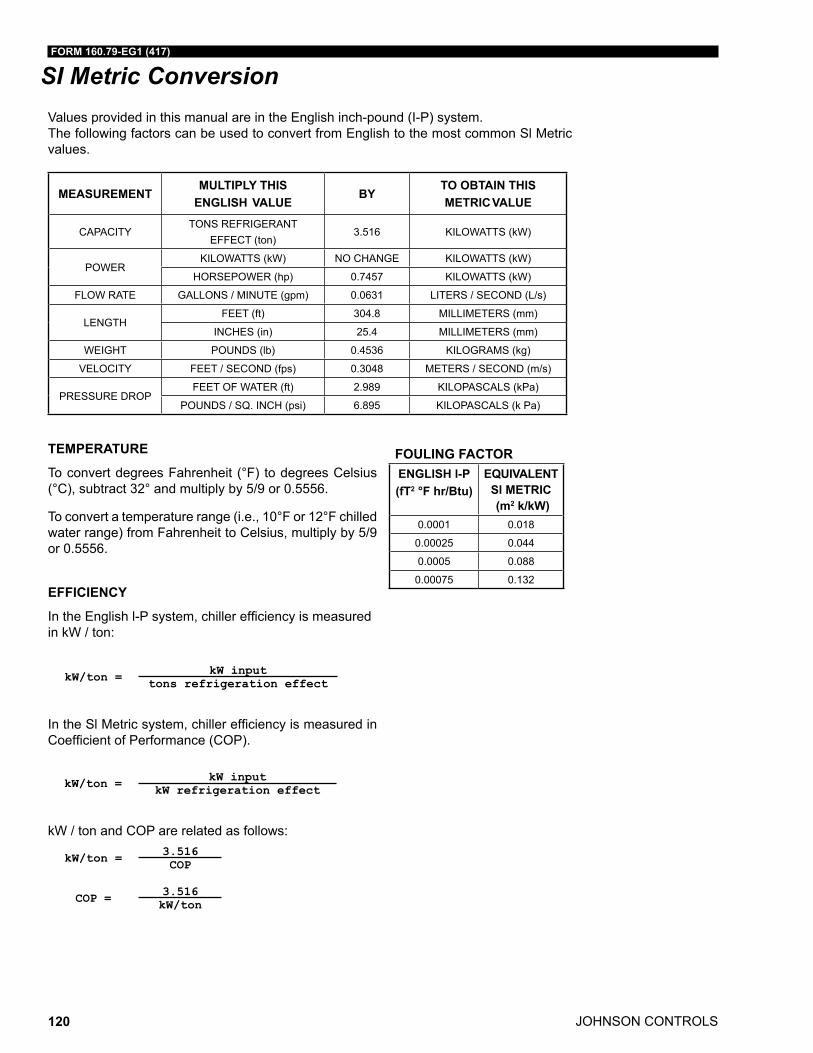
JOHNSON CONTROLS
FORM 160.79-EG1 (417)
120
SI Metric ConversionValues provided in this manual are in the English inch-pound (I-P) system. The following factors can be used to convert from English to the most common Sl Metric values.
TEMPERATURE
To convert degrees Fahrenheit (°F) to degrees Celsius (°C), subtract 32° and multiply by 5/9 or 0.5556.
To convert a temperature range (i.e., 10°F or 12°F chilled water range) from Fahrenheit to Celsius, multiply by 5/9 or 0.5556.
EFFICIENCY
IntheEnglishl-Psystem,chillerefficiencyismeasuredin kW / ton:
kW/ton = kW inputtons refrigeration effect
IntheSlMetricsystem,chillerefficiencyismeasuredinCoefficientofPerformance(COP).
kW/ton = kW inputkW refrigeration effect
kW / ton and COP are related as follows:
kW/ton = 3.516COP
COP = 3.516kW/ton
MEASUREMENTMULTIPLY THIS
ENGLISH VALUEBY
TO OBTAIN THISMETRIC VALUE
CAPACITYTONS REFRIGERANT
EFFECT (ton)3.516 KILOWATTS (kW)
POWERKILOWATTS (kW) NO CHANGE KILOWATTS (kW)
HORSEPOWER (hp) 0.7457 KILOWATTS (kW)
FLOW RATE GALLONS / MINUTE (gpm) 0.0631 LITERS / SECOND (L/s)
LENGTHFEET (ft) 304.8 MILLIMETERS (mm)
INCHES (in) 25.4 MILLIMETERS (mm)
WEIGHT POUNDS (lb) 0.4536 KILOGRAMS (kg)
VELOCITY FEET / SECOND (fps) 0.3048 METERS / SECOND (m/s)
PRESSURE DROPFEET OF WATER (ft) 2.989 KILOPASCALS (kPa)
POUNDS / SQ. INCH (psi) 6.895 KILOPASCALS (k Pa)
FOULING FACTORENGLISH l-P(fT2 °F hr/Btu)
EQUIVALENT Sl METRIC (m2 k/kW)
0.0001 0.018
0.00025 0.044
0.0005 0.088
0.00075 0.132

FORM 160.79-EG1 (417)
JOHNSON CONTROLS 121
NOTES

Printed on recycled paperForm 160.79-EG1 (417) Supersedes: 160.79-EG1 (1216)© 2017 Johnson Controls, Inc. P.O. Box 423, Milwaukee, WI 53201 Printed in USAwww.johnsoncontrols.comIssued on 4/14/2017


![Untitled-1 [] · Glècte GRUHAM LUXURIA Real Luxuria Gate .emple garden / Children 's play area 280 110.3 SQ. YD. 281 - 52 YD. 282 52 SO. YD. 283 - 52 SO. YD. 284](https://static.fdocuments.in/doc/165x107/5f7bcad321e8833a92237a84/untitled-1-glcte-gruham-luxuria-real-luxuria-gate-emple-garden-children.jpg)


