Model UT150L Limit Controller - Yokogawa Electric -199.9 to 500.0˚C 19 Note: Scalling is enable in...
4
General Specifications <<Contents>> <<Index>> Model UT150L Limit Controller GS 05C01E22-01E GS 05C01E22-01E © Copyright Sep. 2005 (YK) 4th Edition Dec. 2015 (YK) n GENERAL The UT150L is an FM approved limit controller that can be configured either as a high limit or as a low limit controller by a user. The UT150L features universal input, two alarm outputs, retransmission output, a timer to count the total time the setpoint is exceeded, and a register to retain the maximum temperature reached. The RS485 communication interface is available optionally. n MODEL AND SUFFIX CODES Model Suffix Codes Descriptions UT150L ........................ Lim-it Controller (1/16 DIN size) Control output –R .............. Relay output Fixed code N .......... Always N Option /AL /EX /RET /RS Alarm outputs (2 points) Digital input (1 point) PV retransmission output in 4 to 20 mA Communication function n MEASURED VALUE INPUT The UT100 series allows you to freely change the input type by software. Table 1. Measured Input Ranges Input Type Range(°C) Range Code(°C) Range(°F) Range Code(°F) Unspecified OFF Thermocouple K -270 to 1370˚C 1 -300 to 2500˚F 31 0.0 to 600.0˚C 2 32.0 to 999.9˚F 32 0.0 to 400.0˚C 3 32.0 to 750.0˚F 33 -199.9 to 200.0˚C 4 -300.0 to 400.0˚F 34 J -199.9 to 999.9˚C 5 -300.0 to 2100˚F 35 T -199.9 to 400.0˚C 6 -300.0 to 750.0˚F 36 E -199.9 to 999.9˚C 7 -300.0 to 1800.0˚F 37 R 0 to 1700˚C 8 32 to 3100˚F 38 S 0 to 1700˚C 9 32 to 3100˚F 39 B 0 to 1800˚C 10 32 to 3200˚F 40 N -200 to 1300˚C 11 -300 to 2400˚F 41 L -199.9 to 900.0˚C 12 -300 to 1600˚F 42 U -199.9 to 400.0˚C 13 -300 to 750˚F 43 Platinel 2 0 to 1390˚C 14 32 to 2500˚F 44 RTD Pt100 -199.9 to 850.0˚C 15 -199.9 to 999.9˚F 45 0.0 to 400.0˚C 16 32.0 to 750.0˚F 46 -199.9 to 200.0˚C 17 -300 to 400˚F 47 -19.9 to 99.9˚C 18 -199.9 to 999.9˚F 48 JPt100 -199.9 to 500.0˚C 19 Note: Scalling is enable in the following 4 range. -1999 to 9999, -199.9 to 999.9, -199.99 to 99.99, -1.999 to 9.999 DC voltage 0 to100 mV 0.0 to 100.0 Note 20 0 to 5 V 0.000 to 5.000 21 1 to 5 V 1.000 to 5.000 22 0 to 10 V 0.00 to 10.00 23 n LIMIT CONTROL FUNCTION (A) (B) (C) (A) (D) (B) lit off lit off on off EXCEEDED Lamp SP HYS PV OUT Lamp Output relay Operation confirmation (not accepted) confirmation (accepted) When a measured value (PV) exceeds a setpoint (SP), “EXCEEDED” lamp lights, and “OUT” lamp turns ON (A). The limit output relay is de-energized then. “EXCEEDED” lamp turns off when PV goes into normal condition, while the output (OUT) display lamp stays on as it is (B). The output (OUT) display lamp turns off when a confirming operation is done by an operator (C). The way to confirm is pressing the “ ” key (or by an external contact, according to the setting of setup parameter DIS). The confirming operation is not accepted during PV exceeds SP (D) (during EXCEEDED lamp lights*). State of output relay is de-energized whenever “OUT” lamp is on. * Check the “HYS” value if the EXCEEDED lamp is not turn off when PV is lower than SP. F01.ai
-
Upload
truonghanh -
Category
Documents
-
view
213 -
download
0
Transcript of Model UT150L Limit Controller - Yokogawa Electric -199.9 to 500.0˚C 19 Note: Scalling is enable in...

GeneralSpecifications
<<Contents>> <<Index>>
Model UT150L Limit Controller
GS 05C01E22-01E
GS 05C01E22-01E© Copyright Sep. 2005 (YK)
4th Edition Dec. 2015 (YK)
n GENERALThe UT150L is an FM approved limit controller that can be configured either as a high limit or as a low limit controller by a user.The UT150L features universal input, two alarm outputs, retransmission output, a timer to count the total time the setpoint is exceeded, and a register to retain the maximum temperature reached.The RS485 communication interface is available optionally.
n MODEL AND SUFFIX CODESModel Suffix Codes Descriptions
UT150L ........................ Lim-it Controller (1/16 DIN size)Control output –R .............. Relay outputFixed code N .......... Always NOption /AL
/EX/RET/RS
Alarm outputs (2 points)Digital input (1 point)PV retransmission output in 4 to 20 mACommunication function
n MEASURED VALUE INPUTThe UT100 series allows you to freely change the input type by software.
Table 1. Measured Input Ranges
Input Type Range(°C) Range Code(°C) Range(°F) Range
Code(°F)Unspecified OFF
Ther
moc
oupl
e
K
-270 to 1370˚C 1 -300 to 2500˚F 310.0 to 600.0˚C 2 32.0 to 999.9˚F 320.0 to 400.0˚C 3 32.0 to 750.0˚F 33
-199.9 to 200.0˚C 4 -300.0 to 400.0˚F 34J -199.9 to 999.9˚C 5 -300.0 to 2100˚F 35T -199.9 to 400.0˚C 6 -300.0 to 750.0˚F 36E -199.9 to 999.9˚C 7 -300.0 to 1800.0˚F 37R 0 to 1700˚C 8 32 to 3100˚F 38S 0 to 1700˚C 9 32 to 3100˚F 39B 0 to 1800˚C 10 32 to 3200˚F 40N -200 to 1300˚C 11 -300 to 2400˚F 41L -199.9 to 900.0˚C 12 -300 to 1600˚F 42U -199.9 to 400.0˚C 13 -300 to 750˚F 43
Platinel 2 0 to 1390˚C 14 32 to 2500˚F 44
RTD
Pt100
-199.9 to 850.0˚C 15 -199.9 to 999.9˚F 450.0 to 400.0˚C 16 32.0 to 750.0˚F 46
-199.9 to 200.0˚C 17 -300 to 400˚F 47-19.9 to 99.9˚C 18 -199.9 to 999.9˚F 48
JPt100 -199.9 to 500.0˚C 19 Note: Scalling is enable in the following 4 range. -1999 to 9999, -199.9 to 999.9, -199.99 to 99.99, -1.999 to 9.999
DC
vol
tage
0 to100 mV 0.0 to 100.0
Note
200 to 5 V 0.000 to 5.000 211 to 5 V 1.000 to 5.000 22
0 to 10 V 0.00 to 10.00 23
n LIMIT CONTROL FUNCTION
(A) (B) (C) (A) (D) (B)
litoff
litoff
onoff
EXCEEDEDLamp
SPHYS
PV
OUTLamp
Outputrelay
Operation confirmation(not accepted)
confirmation(accepted)
When a measured value (PV) exceeds a setpoint (SP), “EXCEEDED” lamp lights, and “OUT” lamp turns ON (A). The limit output relay is de-energized then. “EXCEEDED” lamp turns off when PV goes into normal condition, while the output (OUT) display lamp stays on as it is (B). The output (OUT) display lamp turns off when a confirming operation is done by an operator (C). The way to confirm is pressing the “ ” key (or by an external contact, according to the setting of setup parameter DIS). The confirming operation is not accepted during PV exceeds SP (D) (during EXCEEDED lamp lights*). State of output relay is de-energized whenever “OUT” lamp is on.* Check the “HYS” value if the EXCEEDED lamp is not turn off when PV is lower than SP.
F01.ai
Dec. 15, 2015-00
2
All Rights Reserved. Copyright © 2005, Yokogawa Electric Corporation
<<Contents>> <<Index>>
GS 05C01E22-01E
n HARDWARE SPECIFICATIONSMeasured Value (PV) InputInput: 1 pointInput type: Universal; can be selected by softwareInput accuracy (at 23 ±2°C ambient temperature)
•Thermocouple: ±2°C ±1digitHowever,
• ±4°C for thermocouple input –270 to –100°C • ±3°C for thermocouple input –100 to 0°C • ±5°C for type R and S (±9°C for 0 to 500°C) • ±9°C for type B (accuracy is not guaranteed for 0 to 400°C)
•RTD: ±1°C ±1digit •Voltage(mV, V) : ±0.3% ±1digit
Sampling period for measured value input: 500 msBurn-out detection: Functions for thermocouple or RTD input (burnout upscale only; cannot be switched off)
Input resistance: 1 MΩ or greater for thermocouple or DC mV input. Approx. 1 MΩ for DC V input
Maximum allowable signal source resistance : 250 Ω for thermocouple or DC mV input 2 kΩ for DC V input
Maximum allowable wiring resistance for RTD input: 10 Ω/wire (The resistance values of three wires must be the same.)
Allowable input voltage: ±10 V DC for thermocouple or DC mV input ±20 V DC for DC V input
Noise rejection ratio (50/60Hz): Normal mode noise: Min. 40dB Common mode noise: Min. 120dB (Min. 90dB for DC V input)
Error of reference junction compensation: ±1.5°C (at 15-35°C) ±2.0°C (at 0-50°C) The reference junction compensation cannot be switched off.
Applicable standards: Thermocouple and resistance temperature detector JIS/IEC/DIN (ITS90)
Response time: 2 second or less, 63% (10-90%) (The time required for transmission output to reach 63% of the maximum excursion when PV abruptly changes from 10% to 90%)
Control OutputOutput: 1 pointOutput type: Relay contact output Contact capacity: 3 A at 240 V AC or 3 A at 30 V DC (with resistance load)Note: The control output relay cannot be replaced by users.
Alarm Functions ● Alarm Functions (Option Code /AL)
Alarm types: 22 types (waiting action can be set by software): PV high limit, PV low limit, Deviation high limit, Deviation low limit, De-energized on deviation high limit, De-energized on deviation low limit, Deviation high and low limits, High and low limits within deviation, De-energized on PV high limit, De-energized on PV low limit, Fault diagnosis output, FAIL output
Alarm output: 2 relay contacts Relay contact capacity: 1 A at 240 V AC or 1 A at 30 V DC (with resistance load)Note: The alarm output relays cannot be replaced by users.
Retransmission OutputThe retransmission output is provided only when the /RET option is specified.
Output signal: Measured value in 4-20 mA DCMaximum load resistance: 600 ΩOutput accuracy: ±0.3% of span (at 23±2°C ambient temperature)
Contact InputThe contact inputs are provided only when the /EX option is specified.
Function: Resetting “exceeded status”Input: 1 pointInput type: Non-voltage contact or transistor contact input
Contact capacity: At least 12 V/10 mAOn/off judgment: On state for 1 kΩ or less; off state for 20 kΩ or greater
Communication FunctionThe communication function is provided only when the /RS option is specified. (For details, read the user’s manual of the communication functions IM 05C01E22-10E.) ● Communication Protocol
Personal computer link: Used for communication with a personal computer, or UT link module of the FA-M3 controller (from Yokogawa Electric Corporation).
Ladder communication: Used for communication with a ladder communication module of the FA-M3, or a programmable controller of other manufacturers.
MODBUS communication: Used for communication with equipment featuring the MODBUS protocol. ● Communication Interface
Applicable standards: Complies with EIA RS-485Number of controllers that can be connected:Up to 31
Maximum communication distance: 1,200 mCommunication method: Two-wire half-duplex, start-stop synchronization, non-procedural
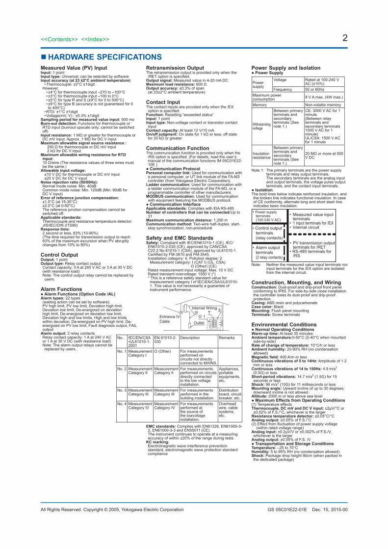
Safety and EMC StandardsSafety: Compliant with IEC/EN61010-1 (CE), IEC/EN61010-2-030 (CE), approved by CAN/CSA C22.2 No.61010-1 (CSA), approved by UL61010-1.Certified by FM-3810 and FM-3545.Installation category: II, Pollution degree: 2 Measurement category: I (CAT I) (UL, CSA)
O (Other) (CE)Rated measurement input voltage: Max. 10 V DCRated transient overvoltage: 1500 V (*)* This is a reference safety standard value for measurement category I of IEC/EN/CSA/UL61010-1. This value is not necessarily a guarantee of instrument performance.
Internal Wiring
OutletEntrance IVCable
IIIO I
T II
No. IEC/EN/CSA •UL61010-1: 2001
EN 61010-2-030
Description Remarks
No. 1 MeasurementCategory I
O (Other) For measurements performed on circuits not directly connected to MAINS.
No. 2 MeasurementCategory II
MeasurementCategory II
For measurements performed on circuits directly connected to the low voltage installation.
Appliances, portable equipments, etc.
No. 3 MeasurementCategory III
MeasurementCategory III
For measurements performed in the building installation.
Distribution board, circuit breaker, etc.
No. 4 MeasurementCategory IV
MeasurementCategory IV
For measurements performed at the source of the lowvoltage installation.
Overhead wire, cable systems, etc.
EMC standards: Complies with EN61326, EN61000-3-2, EN61000-3-3 and EN55011 (CE). The instrument continues to operate at a measuring accuracy of within ±20% of the range during tests.
KC marking: Electromagnetic wave interference prevention standard, electromagnetic wave protection standard compliance
Power Supply and Isolation ● Power Supply
Powersupply
Voltage Rated at 100-240 V AC (±10%)
Frequency 50 or 60HzMaximum power consumption 8 V A max. (4W max.)
Memory Non-volatile memory
Withstandingvoltage
Between primary terminals and secondary terminals (See note 1.)
CE: 3000 V AC for 1minute(Between relay terminals and secondary terminals 1500 V AC for 1 minute)UL/CSA: 1500 V AC for 1 minute
Insulationresistance
Between primary terminals and secondary terminals (See note 1.)
20 MΩ or more at 500 V DC
Note 1: The primary terminals are the power supply terminals and relay output terminals. The secondary terminals are the analog input and output terminals, the voltage pulse output terminals, and the contact input terminals.
● IsolationThe bold lines below indicate reinforced insulation, and the broken line indicates functional insulation. In case of CE conformity, alternate long and short dash line indicates basic insulation.
• Measured value input terminals
• 1 input terminals for /EX• Internal circuit
• Power supply terminals(100-240 V AC)
• Control output terminals (relay contacts)
• Alarm output terminals(2 relay contacts)
• PV transmission output terminals for /RET
• RS-485 terminals for /RS
Note: Neither the measured value input terminals nor input terminals for the /EX option are isolated from the internal circuit.
Construction, Mounting, and WiringConstruction: Dust-proof and drip-proof front panel conforming to IP65. For side-by-side close installation the controller loses its dust-proof and drip-proof protection.
Casing: ABS resin and polycarbonateCase color: BlackMounting: Flush panel mountingTerminals: Screw terminals
Environmental Conditions ● Normal Operating Conditions
Warm-up time: At least 30 minutesAmbient temperature:0-50°C (0-40°C when mounted side-by-side)
Rate of change of temperature: 10°C/h or lessAmbient humidity: 20-90% RH (no condensation allowed)
Magnetic field: 400 A/m or lessContinuous vibrations of 5 to 14Hz: Amplitude of 1.2 mm or less
Continuous vibrations of 14 to 150Hz: 4.9 m/s2 (0.5G) or less
Short-period vibrations: 14.7 m/s2 (1.5G) for 15 seconds or less
Shock: 98 m/s2 (10G) for 11 milliseconds or lessMounting angle: Upward incline of up to 30 degrees; downward incline is not allowed.
Altitude: 2000 m or less above sea level ● Maximum Effects from Operating Conditions
(1) Temperature effectsThermocouple, DC mV and DC V input: ±2μV/°C or ±0.02% of F.S./°C, whichever is the larger
Resistance temperature detector: ±0.05°C/°CAnalog output: ±0.05% of F.S./°C(2) Effect from fluctuation of power supply voltage
(within rated voltage range)Analog input: ±0.2μV/V or ±0.002% of F.S./V, whichever is the larger
Analog output: ±0.05% of F.S. /V ● Transportation and Storage Conditions
Temperature: –25 to 70°CHumidity: 5 to 95% RH (no condensation allowed)Shock: Package drop height 90cm (when packed in the dedicated package)

Dec. 15, 2015-00
3<<Contents>> <<Index>>
All Rights Reserved. Copyright © 2005, Yokogawa Electric Corporation GS 05C01E22-01E
n PANEL CUTOUT DIMENSIONS
Unit: mm
1. General Mounting
min. 70m
in. 7
0
45+0.60
45+0
.6 0
25
25
[(N –1)×48+45] +0.60
+0.6 0
45
2. Side-by-side Close Mounting(Splash-proof construction is unavailable)
N is the number of controllers.If N>5, then measure the actual length.
F02.ai
n EXTERNAL DIMENSIONS
Normal Allowable Deviation= ±(Value of JIS B 0401-1999 tolerance grade IT18) /2
max
. 61
Panel thickness
max
. 47.
8
max
. 44.
8m
ax. 4
4.8
10012
48
48
1 to 10
Unit: mm
F03.ai

Dec. 15, 2015-00
4
All Rights Reserved. Copyright © 2005, Yokogawa Electric Corporation
<<Contents>> <<Index>>
GS 05C01E22-01E
4<<Contents>> <<Index>>
Subject to change without notice.
n TERMINAL ARRANGEMENT
NO
COM
1
2
3
4
5
6
7
8
9
10
11
12
13
14
15
7
8
7
8
6
7
8
+ +B
b
A
ALM2
ALM1
COM
11
12
13
14
15
+1
2 (Note 1)
Retransmission Output
When “/RET” is specified
Alarm outputs
When “/AL” is specified
Measured Value (PV) InputUniversal input-selectable input type
TC Input RTD Input DC mV or V Input
3
4
5
RSB(+)
RSA(-)
SG
RS-485
When “/RS” is specified
4
5
External Contact Input
When “/EX” is specified
Control Output Relay Contact Output
----
--
9L
N10
Power Supply
100-240V AC
RESET
COM
(Note) : /RS and /EX cannot be specitied at the same time.
F04.ai