Model Type Editor - CA...
192
Model Type Editor User Guide Document 0659
Transcript of Model Type Editor - CA...

Model Type Editor
User GuideDocument 0659

NoticeCopyright Notice Copyright © 2002-present by Aprisma Management Technologies, Inc. All rights reserved worldwide. Use, duplication, or disclosure by the United States government is subject to the restrictions set forth in DFARS 252.227-7013(c)(1)(ii) and FAR 52.227-19.
Liability Disclaimer Aprisma Management Technologies, Inc. (“Aprisma”) reserves the right to make changes in specifications and other information contained in this document without prior notice. In all cases, the reader should contact Aprisma to inquire if any changes have been made.
The hardware, firmware, or software described in this manual is subject to change without notice.
IN NO EVENT SHALL APRISMA, ITS EMPLOYEES, OFFICERS, DIRECTORS, AGENTS, OR AFFILIATES BE LIABLE FOR ANY INCIDENTAL, INDIRECT, SPECIAL, OR CONSEQUENTIAL DAMAGES WHATSOEVER (INCLUDING BUT NOT LIMITED TO LOST PROFITS) ARISING OUT OF OR RELATED TO THIS MANUAL OR THE INFORMATION CONTAINED IN IT, EVEN IF APRISMA HAS BEEN ADVISED OF, HAS KNOWN, OR SHOULD HAVE KNOWN, THE POSSIBILITY OF SUCH DAMAGES.
Trademark, Service Mark, and Logo Information SPECTRUM, IMT, and the SPECTRUM IMT/VNM logo are registered trademarks of Aprisma Management Technologies, Inc., or its affiliates. APRISMA, APRISMA MANAGEMENT TECHNOLOGIES, the APRISMA MANAGEMENT TECHNOLOGIES logo, MANAGE WHAT MATTERS, DCM, VNM, SpectroGRAPH, SpectroSERVER, Inductive Modeling Technology, Device Communications Manager, SPECTRUM Security Manager, and Virtual Network Machine are unregistered trademarks of Aprisma Management Technologies, Inc., or its affiliates. For a complete list of Aprisma trademarks, service marks, and trade names, go to:
http://www.aprisma.com/support/secure/manuals/trademark-list.htm
All referenced trademarks, service marks, and trade names identified in this document, whether registered or unregistered, are the intellectual property of their respective owners. No rights are granted by Aprisma Management Technologies, Inc., to use such marks, whether by implication, estoppel, or otherwise. If you have comments or concerns about trademark or copyright references, please send an e-mail to [email protected]; we will do our best to help.
Restricted Rights Notice (Applicable to licenses to the United States government only.)This software and/or user documentation is/are provided with RESTRICTED AND LIMITED RIGHTS. Use, duplication, or disclosure by the government is subject to restrictions as set forth in FAR 52.227-14 (June 1987) Alternate III(g)(3) (June 1987), FAR 52.227-19 (June 1987), or DFARS 52.227-7013(c)(1)(ii) (June 1988), and/or in similar or successor clauses in the FAR or DFARS, or in the DOD or NASA FAR Supplement, as applicable. Contractor/manufacturer is Aprisma Management Technologies, Inc. In the event the government seeks to obtain the software pursuant to standard commercial practice, this software agreement, instead of the noted regulatory clauses, shall control the terms of the government's license.
Virus Disclaimer Aprisma makes no representations or warranties to the effect that the licensed software is virus-free. Aprisma has tested its software with current virus-checking technologies. However, because no antivirus system is 100-percent effective, we strongly recommend that you write protect the licensed software and verify (with an antivirus system with which you have confidence) that the licensed software, prior to installation, is virus-free.
Contact Information Aprisma Management Technologies, Inc., 273 Corporate Drive, Portsmouth, NH 03801 USA
Phone: 603.334.2100U.S. toll-free: 877.468.1448Web site: http://www.aprisma.com
3
Contents
Preface . . . . . . . . . . . . . . . . . . . . . . . . . . . . . . . . . . . . . . . . . . . . . . . . . . . . . . . . . . . . . . 5
Chapter 1: Introduction . . . . . . . . . . . . . . . . . . . . . . . . . . . . . . . . . . . . . . . . . . . . . . . . . 9
SPECTRUM Overview . . . . . . . . . . . . . . . . . . . . . . . . . . . . . . . . . . . . . . . . . . . . . . . . . . 9
About the Model Type Editor . . . . . . . . . . . . . . . . . . . . . . . . . . . . . . . . . . . . . . . . . . . . 10
Using a Developer ID . . . . . . . . . . . . . . . . . . . . . . . . . . . . . . . . . . . . . . . . . . . . . . . . . 10
Activating Your Developer ID . . . . . . . . . . . . . . . . . . . . . . . . . . . . . . . . . . . . . . . . . . . 11
Database Access . . . . . . . . . . . . . . . . . . . . . . . . . . . . . . . . . . . . . . . . . . . . . . . . . . . . 12
Model Types, Models, Attributes, Relations, and Rules . . . . . . . . . . . . . . . . . . . . . . . . . . 12
Model Type Inheritance . . . . . . . . . . . . . . . . . . . . . . . . . . . . . . . . . . . . . . . . . . . . . . . 17
Chapter 2: Using the MTE . . . . . . . . . . . . . . . . . . . . . . . . . . . . . . . . . . . . . . . . . . . . . . . 23
Getting Started . . . . . . . . . . . . . . . . . . . . . . . . . . . . . . . . . . . . . . . . . . . . . . . . . . . . . 23
Protecting Your Database . . . . . . . . . . . . . . . . . . . . . . . . . . . . . . . . . . . . . . . . . . . . . . 24
Starting the Model Type Editor . . . . . . . . . . . . . . . . . . . . . . . . . . . . . . . . . . . . . . . . . . 24
Navigating in the MTE . . . . . . . . . . . . . . . . . . . . . . . . . . . . . . . . . . . . . . . . . . . . . . . . 29
Using the Keyboard to Access Menus . . . . . . . . . . . . . . . . . . . . . . . . . . . . . . . . . . . . . . 32
Common Menu Features . . . . . . . . . . . . . . . . . . . . . . . . . . . . . . . . . . . . . . . . . . . . . . . 33
Closing Out of MTE Operations . . . . . . . . . . . . . . . . . . . . . . . . . . . . . . . . . . . . . . . . . . 35
Using the MTE Dialog Boxes . . . . . . . . . . . . . . . . . . . . . . . . . . . . . . . . . . . . . . . . . . . . 39
Creating a Model Type . . . . . . . . . . . . . . . . . . . . . . . . . . . . . . . . . . . . . . . . . . . . . . . . 47
Destroying a Model Type . . . . . . . . . . . . . . . . . . . . . . . . . . . . . . . . . . . . . . . . . . . . . . 54
Adding or Removing Attributes . . . . . . . . . . . . . . . . . . . . . . . . . . . . . . . . . . . . . . . . . . 55
Model Type Migration . . . . . . . . . . . . . . . . . . . . . . . . . . . . . . . . . . . . . . . . . . . . . . . . . 71
Editing Attributes . . . . . . . . . . . . . . . . . . . . . . . . . . . . . . . . . . . . . . . . . . . . . . . . . . . . 71
Creating and Managing an Attribute Group . . . . . . . . . . . . . . . . . . . . . . . . . . . . . . . . . . 83
Creating and Removing Relations . . . . . . . . . . . . . . . . . . . . . . . . . . . . . . . . . . . . . . . . 93
Creating and Removing Meta–Rules . . . . . . . . . . . . . . . . . . . . . . . . . . . . . . . . . . . . . . 100
Chapter 3: The MTE Views . . . . . . . . . . . . . . . . . . . . . . . . . . . . . . . . . . . . . . . . . . . . . 105
Using the MTE Views . . . . . . . . . . . . . . . . . . . . . . . . . . . . . . . . . . . . . . . . . . . . . . . . 105
Model Type View Fields . . . . . . . . . . . . . . . . . . . . . . . . . . . . . . . . . . . . . . . . . . . . . . . 107
The Attribute View . . . . . . . . . . . . . . . . . . . . . . . . . . . . . . . . . . . . . . . . . . . . . . . . . . 112
Attribute View Fields . . . . . . . . . . . . . . . . . . . . . . . . . . . . . . . . . . . . . . . . . . . . . . . . 113
The Attribute Edit View . . . . . . . . . . . . . . . . . . . . . . . . . . . . . . . . . . . . . . . . . . . . . . . 121
Attribute Edit View Fields . . . . . . . . . . . . . . . . . . . . . . . . . . . . . . . . . . . . . . . . . . . . . 122
The Relation View . . . . . . . . . . . . . . . . . . . . . . . . . . . . . . . . . . . . . . . . . . . . . . . . . . 135
Relation View Fields . . . . . . . . . . . . . . . . . . . . . . . . . . . . . . . . . . . . . . . . . . . . . . . . . 135
The Meta-Rule View . . . . . . . . . . . . . . . . . . . . . . . . . . . . . . . . . . . . . . . . . . . . . . . . . 139
4 Model Type Editor User Guide
Contents
Meta–Rule View Controls and Indicators . . . . . . . . . . . . . . . . . . . . . . . . . . . . . . . . . . . 140
Chapter 4: Importing and Exporting Model Types . . . . . . . . . . . . . . . . . . . . . . . . . . . 143
Importing and Exporting Model Types . . . . . . . . . . . . . . . . . . . . . . . . . . . . . . . . . . . . . 143
Using the MTE to Import Model Types . . . . . . . . . . . . . . . . . . . . . . . . . . . . . . . . . . . . . 144
Using the MTE to Export Model Types . . . . . . . . . . . . . . . . . . . . . . . . . . . . . . . . . . . . . 146
Using dbtool to Export or Import Model Types . . . . . . . . . . . . . . . . . . . . . . . . . . . . . . . 151
Importing a MIB . . . . . . . . . . . . . . . . . . . . . . . . . . . . . . . . . . . . . . . . . . . . . . . . . . . 162
Chapter 5: The MTE Reports Utility . . . . . . . . . . . . . . . . . . . . . . . . . . . . . . . . . . . . . . . 169
Reports . . . . . . . . . . . . . . . . . . . . . . . . . . . . . . . . . . . . . . . . . . . . . . . . . . . . . . . . . . 169
Command Line Help . . . . . . . . . . . . . . . . . . . . . . . . . . . . . . . . . . . . . . . . . . . . . . . . . 170
Running a Relations Report . . . . . . . . . . . . . . . . . . . . . . . . . . . . . . . . . . . . . . . . . . . . 170
Running a Model Type Attributes Report . . . . . . . . . . . . . . . . . . . . . . . . . . . . . . . . . . . 172
Directing Reports to an Output Device . . . . . . . . . . . . . . . . . . . . . . . . . . . . . . . . . . . . 176
Chapter 6: MTE Resources . . . . . . . . . . . . . . . . . . . . . . . . . . . . . . . . . . . . . . . . . . . . . . 179
Default MTE Resource File . . . . . . . . . . . . . . . . . . . . . . . . . . . . . . . . . . . . . . . . . . . . . 179
Redefining MTE Resources . . . . . . . . . . . . . . . . . . . . . . . . . . . . . . . . . . . . . . . . . . . . . 179
Index . . . . . . . . . . . . . . . . . . . . . . . . . . . . . . . . . . . . . . . . . . . . . . . . . . . . . . . . . . . . . . 187

5
Preface
This manual describes the features and operation of the Model Type Editor (MTE), providing information necessary for using the MTE for SPECTRUM 6.5.0. The MTE is one of several SPECTRUM Level I toolkits. which collectively provide the capability to add support for additional devices and to enhance or modify aspects of the SPECTRUM core without having to write C++ code.
Who Should Read this Guide
This manual is intended to be used by experienced network administrators and developers who want to add extensions (such as new or customized management modules) to SPECTRUM®, or want to extend or customize the client programs to access the SPECTRUM knowledge-base. You should read this manual if you are going to:
• Create, remove, or modify SPECTRUM model types, attributes, or relations.
• Import a Management Information Base (MIB) text file.
• Import and export model types.
For general information on network administration procedures, refer to How to Manage Your Network with SPECTRUM and other documents in the Administering area of the SPECTRUM document set. For general information on using the views, menus, and utilities available in SPECTRUM, refer to Getting Started with SPECTRUM for Operators, SPECTRUM Views, and other documents in the Operating area of the document set.
What is in this book
This guide contains the following chapters:
• Chapter 1: Introduction - This chapter provides a brief overview of SPECTRUM and the Model Type Editor (MTE) and tells you how to load your own Developer ID to identify database elements you create with the MTE. The chapter also outlines the basic relationships between those elements (model types, attributes, relations, and rules) and provides basic information you need to know about model type inheritance in order to use the MTE correctly for working with and creating any of these elements.
• Chapter 2: Using the MTE - This chapter describes procedures to help you start the MTE and use it to create, remove, and modify model types in your database.

6 Model Type Editor User Guide
Preface
• Chapter 3: The MTE Views - This chapter provides details concerning the various MTE views: the Model Type View, the Attribute View, the Attribute Edit View, the Relation View, and the Rule View. This coverage presumes that the reader is familiar with the use of keyboard commands and mouse manipulations, as well as the various common dialog boxes, as discussed in the preceding chapter.
• Chapter 4: Importing and Exporting Model Types - This chapter describes MTE options and tools that you can use to: (1) Import and export model types using the MTE (together with procedures for importing and/or exporting model types or analyzing the contents of export files by use of the dbtool utility); (2) Import a MIB (Management Information Base) file to be used as the basis for a new or customized model type.
• Chapter 5: The MTE Reports Utility - This chapter describes how to run the MTE Reports Utility and select the information you want to extract. This utility gathers model type and relation information from the database and produces a formatted report on your workstation’s standard output device.
• Chapter 6: MTE Resources - This chapter lists unique resources used to configure basic features of the MTE. The representation of the Spectrum/app-defaults/mte file at the beginning of this appendix shows the default values initially supplied with SPECTRUM 5.0. The following text then explains how these can be modified to satisfy individual user preferences or needs. For more information on how to edit resources, refer to “Redefining MTE Resources” on page 179.
Typographical Conventions
Certain typographical conventions are used throughout this document to distinguish between program names, variables, etc., as follows:
• Code examples and screen messages appear in regular Courier type if showing system display or output, in boldface Courier if showing what you should type into the system.
• Cross-references to other sections, tables, or figures in this publication provide the actual page number and when appropriate give the applicable titles in italic text. In the PDF distribution format, these cross-references are colored blue to show that they are active hypertext links to the referenced location.
• Titles of other SPECTRUM publications appear in italic text.
• Executable script and program names appear in Courier. For example, the utility named “dbtool” appears as dbtool. (One significant exception to this convention is the mte utility itself, which is given as mte when clearly talking about the program as a program function but is called MTE when referenced as an entity.)
• To reduce potential confusion in text, names of model types generally are set in boldface Courier and names of attributes are set in boldface Courier italics.
• Keyboard controls and display-screen nomenclature (labels, button names, etc.) are given in boldface type—such as the Return key and the OK button.
• Command names are printed in bold; for example, Save & Close or Cancel.
• Menu selections to open a menu or submenu or to open a view or a dialog box are printed bold—for example: Examine Attributes or Set Filter…. Submenu options are indicated by a

Model Type Editor User Guide 7
right-angle character (>) between the menu and the submenu—for example: “Activate the File > Toggle Warnings option.”
• Italics are used for emphasis—especially in the case of a first-time use of an important term or phrase or when the SPECTRUM-specific meaning of such a term or phrase is being defined.
In addition, the following graphical conventions apply for callouts in illustrations throughout this publication:
This publication is written from the perspective of an X Windows (Motif) windowing environment perspective. If you are using another interface (e.g., Open Look), views and mouse functionality will vary according to the interface you are using.
Related Reading
The following Aprisma documents contain further information on topics discussed in this guide:
• Concepts Guide
• CORBA API Programmer Guide
• Defining SPECTRUM Resources
• How to Manage Your Network with SPECTRUM
• SPECTRUM Extension Integration Toolkit Guide
• SPECTRUM GIB Editor Guide
• SPECTRUM Icons
• SPECTRUM Menus
• Generic SNMP Device Management User Guide and Toolkit
• SPECTRUM Views
Refer to the following documentation for more information on using SPECTRUM and managing TCP/IP-based networks.
• LAN Troubleshooting Handbook, Mark Miller (1989, M&T Publishing, Inc.), 2nd Edition, 1993
• The Simple Book — An Introduction to Management of TCP/IP-based Internets, Marshall T. Rose, Performance Systems International, Inc., 2nd Edition, 1994
• Computer Networks, Andrew S. Tanenbaum, Prentice-Hall, Inc.
To learn more about FDDI, refer to the following document:
• A Primer to FDDI: Fiber Distributed Data Interface, Digital Equipment Corporation.
1. Images of this color, and shading, containing regular text, represent steps that you must perform in the sequence of the number in the upper left corner.
Images of this color and shading, containing italic text, represent informative notes about the thing(s) being discussed.

8 Model Type Editor User Guide
Preface
To learn more about the FDM, refer to the following document:
• FDMMIM, FDMMIM-04, FDMMIM-24, and FDMMIM-30 FDDI Concentrator Ethernet to FDDI Bridge Modules Installation and User’s Guide, Enterasys Networks.
9
Chapter 1: Introduction
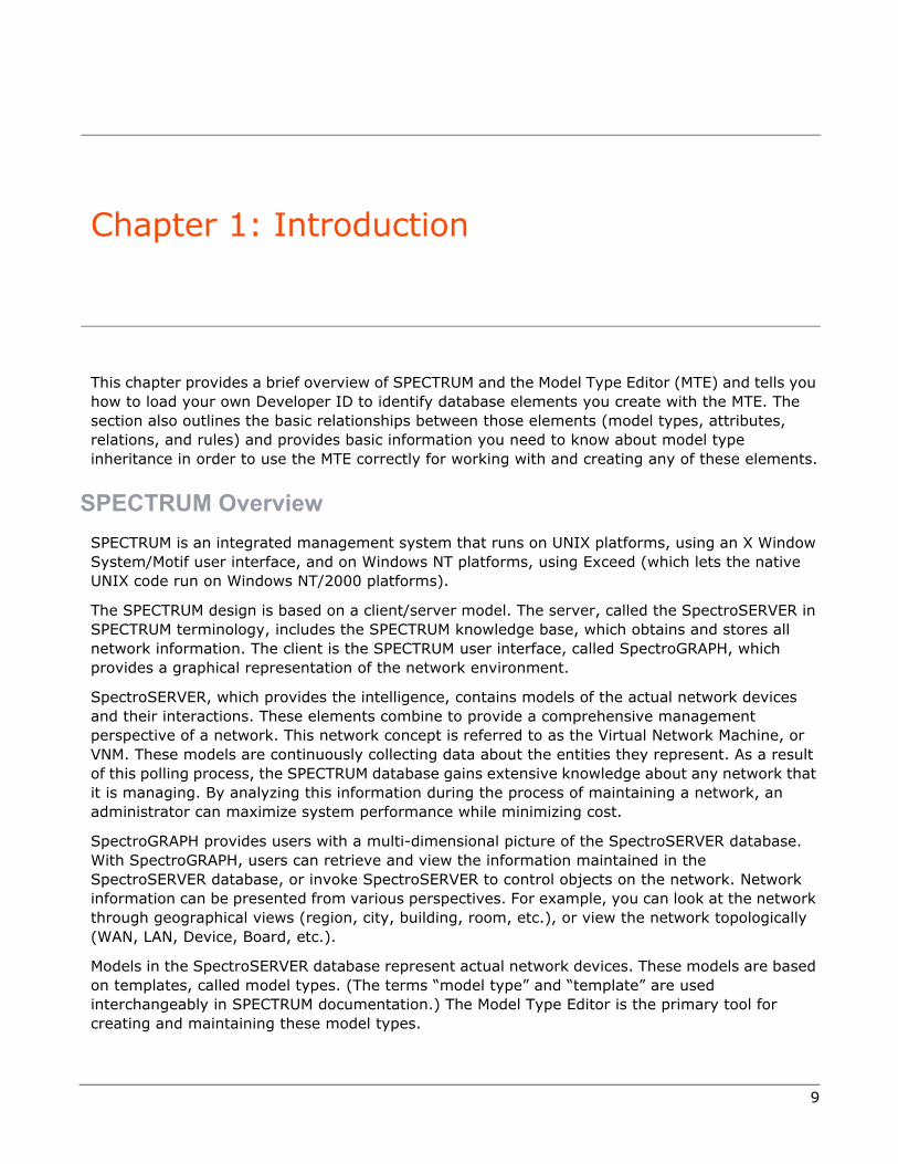
This chapter provides a brief overview of SPECTRUM and the Model Type Editor (MTE) and tells you how to load your own Developer ID to identify database elements you create with the MTE. The section also outlines the basic relationships between those elements (model types, attributes, relations, and rules) and provides basic information you need to know about model type inheritance in order to use the MTE correctly for working with and creating any of these elements.
SPECTRUM OverviewSPECTRUM is an integrated management system that runs on UNIX platforms, using an X Window System/Motif user interface, and on Windows NT platforms, using Exceed (which lets the native UNIX code run on Windows NT/2000 platforms).
The SPECTRUM design is based on a client/server model. The server, called the SpectroSERVER in SPECTRUM terminology, includes the SPECTRUM knowledge base, which obtains and stores all network information. The client is the SPECTRUM user interface, called SpectroGRAPH, which provides a graphical representation of the network environment.
SpectroSERVER, which provides the intelligence, contains models of the actual network devices and their interactions. These elements combine to provide a comprehensive management perspective of a network. This network concept is referred to as the Virtual Network Machine, or VNM. These models are continuously collecting data about the entities they represent. As a result of this polling process, the SPECTRUM database gains extensive knowledge about any network that it is managing. By analyzing this information during the process of maintaining a network, an administrator can maximize system performance while minimizing cost.
SpectroGRAPH provides users with a multi-dimensional picture of the SpectroSERVER database. With SpectroGRAPH, users can retrieve and view the information maintained in the SpectroSERVER database, or invoke SpectroSERVER to control objects on the network. Network information can be presented from various perspectives. For example, you can look at the network through geographical views (region, city, building, room, etc.), or view the network topologically (WAN, LAN, Device, Board, etc.).
Models in the SpectroSERVER database represent actual network devices. These models are based on templates, called model types. (The terms “model type” and “template” are used interchangeably in SPECTRUM documentation.) The Model Type Editor is the primary tool for creating and maintaining these model types.

10 Model Type Editor User Guide
Chapter 1: Introduction
About the Model Type EditorThe Model Type Editor (MTE) is a utility that operates in the X Window System environment—or, via Exceed, in Windows NT. You can use the MTE to modify, add, or remove model types, attributes, and relations, letting you tailor your database to your specific network design.
Using a Developer IDThe MTE uses Developer IDs to establish a unique identifier (handle) for each model type, attribute, and relation. Whenever a model type, attribute, or relation is created, the Developer ID becomes part of the resulting handle.
A developer’s Developer ID determines privileges of access and use for model types and attributes. There are two classes of Developer ID:
Default ID — The Developer ID applied when the current MTE user is not registered with Aprisma Management Technologies, Inc., as a SPECTRUM developer; the code designation is DF, with a Developer ID value of 0xffff.
Registered ID — A unique Developer ID that protects a developer’s model types, attributes, relations, and rules from being edited by other developers.
For information on obtaining a registered Developer ID, see the SPECTRUM Concepts Guide (0647).
Developers using the Default Developer ID with the MTE can edit and export only those model types and attributes that were created with the Default Developer ID. Any developer can use the MTE as a default developer, however, model types and attributes created using the Default Developer ID are not protected. In addition, using the Default Developer ID means you can only view a model type created by other developers if the model type in question has its Visible flag set or the model type was created with the Default Developer ID.
Depending on your particular Developer ID, you can use the MTE to perform several database editing tasks.
Using a Default Developer ID the MTE lets you perform the following tasks:
• View Visible-flagged model types created by other registered developers.
• View, create, destroy, or modify model types and attributes created with the Default Developer ID.
• Modify the derivation of model types created with a Default Developer ID by adding or removing base model types.
• Create and edit rules and relations created with the Default Developer ID.
• Remove rules and relations created with the Default Developer ID.
• Export model types, relations, and rules created with the Default Developer ID.
• Import model types, relations, and rules from another compatible database.
• Import a Management Information Base (MIB) text file.

Activating Your Developer ID
Model Type Editor User Guide 11
As a registered developer with your own Developer ID information loaded into the current database, and using your Developer ID, the MTE allows you to perform the following operations:
• View Visible-flagged model types created by other registered developers.
• View, create, destroy, or modify model types and attributes created with your (same) Developer ID.
• Modify the derivation of model types by adding or removing base model types created with your (same) Developer ID.
• Create and edit relations and rules created with your (same) Developer ID.
• Destroy rules and relations created with your (same) Developer ID.
• Export model types, relations and rules created with your (same) Developer ID.
• Import model types, relations, and rules from another compatible database.
• Import a Management Information Base (MIB) text file.
Caution: The MTE requires exclusive access to a SPECTRUM database. No other program is permitted access while you are editing or creating model types for your network, and SpectroSERVER and SpectroGRAPH operation must be halted before you can start the MTE.
Note: You cannot destroy a relation or a rule that you do not own—that is, that was not created with the same Developer ID loaded in your database.
Caution: Model types, relations, and rules can only be imported from a compatible SPECTRUM database (used with the same SPECTRUM release level and created with your (same) Developer ID). Refer to the SPECTRUM Installation Guide for more information on updating a SPECTRUM database used with a prior release of SPECTRUM.
Regardless of your Developer ID, the MTE cannot create new SpectroSERVER database intelligence.
Activating Your Developer IDCaution: The -d option can be used only once to load developer information, until such time as you reload your modeling catalog into your database. This reloading clears the developer information, and you will have to reload your Developer ID after each such occurrence. Attempting to execute a second SSdbload using the -d option will produce an error message and will leave the previously loaded developer information unchanged.
As a registered developer, you are permitted to load a registered Developer ID value, unique to your firm. Developer information can be loaded only once, after your database is loaded (but also must be reloaded each time you reload your database).
To add developer information to a database, move to the directory containing your database (normally, Spectrum/SS) and then type in the command line for initializing the database as follows:
../SS-Tools/SSdbload -d <path/developer filename>

12 Model Type Editor User Guide
Chapter 1: Introduction
If the system responds by displaying an error message in the following format, the database is locked by a current or previous user (for example, some operator is running SpectroSERVER, or some application was last down incorrectly by the last person to access the database:
Database already locked by: <user>,by process: <as applicable>,
by process ID: <as applicable>,on network node: <as applicable>,
which started at: <mm/dd/yyyy_hh:mm:dd>.
<mm dd hh:mm:ss> ERROR at <path>: cannot lock database (already locked) @ <path>
MTE shutting down
MTE shut down complete
Refer to “Getting Started” on page 23 for information on removing the lock.
Conversely, you may get a message such as the following:../SS-Tools/dbtool.export SM-SFPS.m
Error: One or more of the SPECTRUM database files is missing read and/or write permissions
This latter message simply means that your current login identification does not have access to the Spectrum database; switch to root and repeat the command.
Database AccessConcurrent access from multiple users/applications is currently not permitted. SPECTRUM applies a soft lock file (.VNMDB.LOCK) to prevent access from more than one Aprisma-developed application at the same time. However, non-Aprisma tools and/or applications may not check for this lock, and you must exercise care with such things so as to prevent two programs from accessing the database at the same time.
Cautions appear throughout this manual to warn against concurrent access. Under certain circumstances (for example, recovering from an abnormal shutdown), the soft lock file can be removed. Refer to “Getting Started” on page 23 for more information on removing the lock.
For more information about database loading, back-up, tools and maintenance, refer to the following SPECTRUM manuals: Database Management, Performance View User’s Guide, and Defining SPECTRUM Resources.
Model Types, Models, Attributes, Relations, and RulesTo understand how SPECTRUM monitors your network, it is important to understand model type derivations, model types, models, attributes, relations and rules. Model types are templates used

Model Types, Models, Attributes, Relations, and Rules
Model Type Editor User Guide 13
to create models; models are specific instances of a model type. Attributes are the characteristics associated with a particular model type. Relations and rules define how model types interact with each other.
Model Types
A model type is a template which is defined by a specific combination of attributes. Attributes are database constructs— variables which collectively characterize the real-world objects represented by the associated model type. Model types range from very simple (few attributes) to very complex (many attributes). The MTE provides an Attribute View that lets you examine the different attributes associated with a given model type, listing a variety of information about each such attribute.
Complex model types are often derived by inheriting attributes from several simpler model types. The resulting combination constitutes a hierarchy of model types. Parent model types (model types from which one or more other model types have been derived) are called base model types. Child model types (model types which have been derived from one or more other types) are called derived model types. Refer to “Editing Attributes” on page 71 for more detailed information on changing model type attribute extensions.
Figure 1-1 on page 13 shows a sample model type hierarchy that illustrates model type derivation.
Figure 1-1: Example of Derived Model Types
In this figure, Devices is a base model type for Bridge, Hubs, and PC Cards, all three of which are derived from the Devices model type, while SNMP Protocol is an optional model type that is being used as a base model type for three new model types respectively derived from those three. The SNMP Bridge model type is created by using both Bridge and SNMP Protocol as base model types, thereby inheriting all of the attributes from both of those base model types. Similarly, SNMP MMAC is derived from SNMP Protocol and Hubs, while SNMP DNI PC Card is derived from SNMP
SNMP
PC Cards
SNMP
Protocol*BridgeHubsPC Cards
Devices
Attributes inherited from Devices and Bridges
Attributes inherited from SNMP Protocol
* SNMP Protocol is an optional Management Module.
Attributes inherited from Devices
Attributes inherited from Devices and Hubs
Attributes inherited from Devices and PC Cards
SNMP
Bridge
SNMP
MMAC

14 Model Type Editor User Guide
Chapter 1: Introduction
Protocol and PC Cards. The MTE helps you through these hierarchal relationships by providing a Model Type View that lists the base model types from which a given model type is derived, while simultaneously listing any model types that have been derived from that same model type.
Models
A model, as built by the SpectroSERVER, is an instantiation of a model type. All models built from the same model type have the same collection of attributes and SPECTRUM intelligence. The values for the attributes are unique for each model, however, except for the case of Shared attributes.
Figure 1-2 on page 14 shows an example of three model types derived from a model type named Building. All of these three model types derived from Building include attributes called Model_Name and Floors among their attributes, but the values for these attributes vary from model to model. The table in the lower left corner of the figure shows how the attribute values for each of the three model types in this example that might be varied by a user, where the Model_Name attribute could be used to designate what sort of building is being modeled and the value of the Floors could be used to identify how many floors were in each type of building.
Figure 1-2: Model Types and Models
The network administrator can add, edit, and delete models through SpectroGRAPH. For more information on adding and editing and deleting models, refer to How to Manage Your Network with SPECTRUM.
Attributes
There are various rationales for attributes. Certain attributes, such as the name of a router, its IP address, etc., are necessary in order to uniquely identify a resulting model within the SPECTRUM database. Other attributes relate a model to the SNMP OIDs supported by that model. Still others support SPECTRUM functionality— such as Discovery_Precedence (used by the AutoDiscovery program), Value_When_Red (used for alarm roll-up), or Polling_Interval (which determines how often SPECTRUM polls the given device for information).
Value of Model_NameAttribute
Value of FloorsAttribute
Warehouse 3
Headquarters 7
Field Office 1
Instances of the Building model type
Model types are used to create models.
Building model type
Warehouse (3 floors) of type Building
Headquarters (7 floors)of type Building
Field Office (1 floor)of type Building

Model Types, Models, Attributes, Relations, and Rules
Model Type Editor User Guide 15
Relations
In SPECTRUM, how a model of one model type can interact with a model of another model type is determined by the set of relations defined for each given model type. Each such relation is defined by one or more rules—and usually includes several such rules. In the creation of a model type, a more applicable term is meta-rule. In SPECTRUM terminology, then, meta-rules define the relationships between model types, and SpectroGRAPH subsequently uses these model type meta-rules to establish the rules for interaction between specific models created from these model types.
These meta-rules apply the relation to a specific pair of model types. The following example shows a typical Contains meta-rule, as defined in the Meta-Rules view (see Figure 2-54 on page 101):
Country Contains Building
A model may exist not only in its own right but also in relation to other models. In the previous example, the Country model type relates to the Building model type in this way: Country contains Building. The word Contains describes a relation that has been specified between instances of Country and Building model types, for example, and the statement “France contains Corp1” could be an instance of a rule pertaining to that relationship. SPECTRUM understands many such relations, each being defined by one or more meta-rules defining specific instances of this same nature. Other examples of relations are collects, encompasses, and is adjacent to, to name just a few.
Some relations describe how a single model of one model type can relate to a number of models of another model type. For example, a single model of the Building model type can contain many models of the Room model type. So Contains in this instance is a one-to-many relation.
Other relations describe how a number of different models of one model type can relate to a number of models of another model type. For example, many models of the Host_Dell model type can be adjacent to many models of the Host_Sun model type. So adjacent to in that instance is a many-to-many relation.
For any given relation, the relation type must be defined either as one-to-many or as many-to-many. Once the new relation has been confirmed by being saved, the relation type cannot be changed. (If change is necessary, you must remove the existing relation and then create a new one with the desired relation type setting.)
Each specific instance of a relation of either type (one-to-many or many-to-many) is called a meta-rule. The MTE provides a Rule View that lets you examine each and every meta-rule defined for a given relation with respect to a specific model type.
Meta-Rules
You can create or destroy meta-rules according to the needs of the network design. You can add meta-rules as desired, but you cannot remove a meta-rule from the database unless that meta-rule originally was created under the same Developer ID currently loaded in your database. The following list shows some of the meta-rules for the Contains relation for a given model type:

16 Model Type Editor User Guide
Chapter 1: Introduction
Note that each meta-rule must have exactly one predicate model type (the left-hand entry) and exactly one antecedent model type (the right-hand entry). Any given model type may be an antecedent (left-side element) for any desired number of meta-rules— and also may be a predicate (right-side element) for any desired number of meta-rules.
Each relation in the knowledge base that comes with the basic SPECTRUM package can have meta-rules that specify the model types to which the relation is applied. Since these meta-rules are defined for the relation to which they pertain, the format for defining meta-rules specifies only those specific model types that are part of the knowledge base of the basic SPECTRUM package.
Note: The current release of SPECTRUM cannot automatically migrate meta-rules, deletions, or modifications. You must manually modify or delete the meta-rules in the new release or update them in order to maintain any values or relationships you established for the previous version.
When a new model type is derived from one that is specified as a member of a meta-rule in a relation, the meta-rule automatically applies to the derived model type. For example, the knowledge base has a relation called Contains and model types named Room and Device. One of the meta-rules for the Contains relation is [Room, DEVICE]. This means that a Room can Contain a Device. If you derive a new model type named Workstation from the model type named Device, a new [Room, Workstation] meta-rule is automatically generated. This new meta-rule states that Room can Contain a Workstation. You, as the model type designer, thus do not have to add this meta-rule explicitly.
Meta-rules are not automatically applied when a new relation is added to the knowledge base using the MTE, however. In these cases, you must explicitly add new meta-rules. For more information, refer to “Creating a New Relation” on page 94.
Instantiation of a meta-rule between two models produces an association between the models, and each model can react to the knowledge that it is associated with the other model. If you add a new relation, therefore, you must add new intelligence and meta-rules to the model types so that the resulting models will react when they are associated with other models under the new relation. For example, assume that you add to the knowledge base a new meta-rule, Sends_mail_to, which relates two models of a model type, named User.
When the meta-rule is instantiated (for example, when one User model sends mail to a second User model), the first model may need to react to the fact that it (the user that it represents) has sent mail, and the second model may need to react to the fact that it has received mail. In this case, you must add intelligence to the User model type to implement these reactions. This type of intelligence must be implemented programatically with the CORBA API. See the CORBA API Programmer Guide for more information.
Country Contains Region
Country Contains Site
Country Contains Building
Building Contains Floor
Building Contains Room

Model Type Inheritance
Model Type Editor User Guide 17
Model Type InheritanceThe information in your database, as indicated in the foregoing discussion, consists of model types, attributes, extensions, relations, meta-rules, and developer information. The following constraints apply to all model types and derived model types when using the MTE:
• Currently, editing another developer’s attribute extension or another developer’s model type is not guaranteed to survive the next upgrade. You should note any such changes that you make, as you may need to re-apply the changes manually after upgrading to the next SPECTRUM version release.
• If a model type is derived from two or more base model types having a common ancestral model type in the hierarchy, that model type can inherit common attributes and intelligence from each such base model type. The way SPECTRUM handles this situation is to give the highest-ranking base model type precedence over lower-ranking model types. (You can change the ranking order as desired, to fit specific requirements; refer to the note and following procedure on page 50.)
• You cannot remove a meta-rule that was supplied by another developer—that is, that was created under a different Developer ID than the one currently loaded in your database.
• If you set an attribute’s Group ID to another developer’s attribute, and that developer’s attribute is not distributed with the next release/upgrade, the Group ID you changed will become set to a <No Group> value.
Editing Attribute Extensions
A model type attribute represents a “binding” of a model type’s attribute description, an attribute extension, and its default (or shared) value. An attribute description is composed of elements called descriptors; these descriptors become inherited by all model types derived from base model types that contain them, and cannot be modified or removed except at the base model type level. This means that you cannot change these descriptors in a derived model type. However, if you are using the same Developer ID under which an attribute descriptor was created (meaning you “own” it), then you navigate up through the hierarchy to the original base model type (sometimes called the “originating” model type or simply the originator) where the descriptor was created and change or remove it.
If you do this, that same change will automatically occur in all derived model types sharing that same attribute source. If you attempt to change or remove these attribute descriptors at a derived model type, however, the MTE will present an error message telling you that you cannot do it. In most cases, in fact, you will find that modification-screen selections pertaining to those descriptors are “grayed out,” indicating that you cannot change the current settings.
Specialization of Attribute Extensions
In the case of attribute extensions, however, you can modify or remove the associated elements at every model-type level in a derivation branch. This process is called specialization, and the affected extension (and the derived model type) is said to have been specialized, with the changed value overriding the inherited one. If you change the attribute extension of a base model type, therefore, all unspecialized model types derived from that base model type throughout the hierarchy are also automatically modified to match the new attribute descriptor in the base model type, but any specialized derived model types will retain their specialized values. The number of

18 Model Type Editor User Guide
Chapter 1: Introduction
allowable different derived model types is limited only by the number of attribute extensions the user chooses to create or modify.
The specifics of model type and attribute inheritance are important in model type derivation, because the functionality of each model type depends on its inheritance.
Normal Hierarchal Sequence
Figure 1-3 on page 18 depicts attributes being inherited through a normal hierarchal sequence.
Figure 1-3: Model Type Attribute Inheritance
The figure diagrams a sequence in which Derived Model Type A first was derived from a base model type, and then Derived Model Type B subsequently was derived from Derived Model Type A. As a result, Derived Model Type B has an attribute also derived from Derived Model Type A, with its extension and value being identical to the extension and value of the same attribute in Derived Model Type A. In addition, both the extension and value of that attribute in Derived Model Type B also match the extension and value of the same attribute in the base model type, from which Derived Model Type A was derived. This same correspondence will be repeated for any other model types derived from Derived Model Type A or from Derived Model Type B or from other model types derived from either of these. Moreover, this relationship is maintained by the database, so that any change made in the given attribute extension or value in the base model type will immediately be reflected in all of the derived model types which inherit that attribute extension and that value.
As a trivial example, the developer of a base model type could add a Technical_Assistance attribute providing a telephone number text-string as its value. That same attribute (and phone number value) would then appear as an operator-viewable attribute in all model types derived from that base model type, in all model types derived from those derived model types, etc. If the developer’s facility were subsequently changed such that a different telephone number was assigned for technical assistance, the developer only has to change the number-designation value of the Technical_Assistance attribute in the base model type; the same new number would immediately appear as the value for that inherited attribute in Derived Model Type A, in Derived Model Type B, and in all other model types derived from that base model type.
Base Model Type
Derived Model Type A
Derived Model Type B
Links to base model type’s attribute descriptor extension
Model type derivation hierarchypath
Links to base model type’s attribute value
AttributeDescriptor Extension 1
Value 1
AttributeDescriptorExtension 1Value 1
AttributeDescriptionExtension 1Value 1

Model Type Inheritance
Model Type Editor User Guide 19
Specialized Hierarchal Sequence
Figure 1-4 illustrates the somewhat different situation that exists when changed attribute extensions or values are inherited. Suppose we assume the same derivation sequence as in the previous example, except that in this case the developer for some reason changes the value of the attribute in Derived Model Type A, thereby specializing that model type with respect to that attribute’s value. From that time on, there is no link between Derived Model Type A and the base model type with respect to that specific value—but the link for the attribute extension continues to be valid, maintaining the same attribute ID, the same flag settings, etc. Given this situation, Derived Model Type B continues to have an attribute value that matches the attribute value of Model Type A (which constitutes a base model type for Model Type B)— that is, the corresponding attribute value will exhibit the same change that was made in Derived Model Type A, even if Model Type B was derived before that change was made, whereas the attribute extension in Derived Model Type B continues to match the attribute extension of the base model type from which Model Type A was derived.
Figure 1-4: Model Type Attribute Specialization
To illustrate this condition, consider the case of a developer of a given sequence of model types having the Technical_Assistance phone number as an attribute, as described in the preceding example. Suppose the developer decides to specialize the derived types with respect to that attribute and assigns a different telephone number as the text-string value for that attribute in the case of Derived Model Type A. After this change, the new Value_2 telephone number value appears for the Technical_Assistance attribute in Derived Model Type B and any model types derived from it (whether derived before or after the change is made). The base model type, however, continues to identify the original Value_1 telephone number text-string.
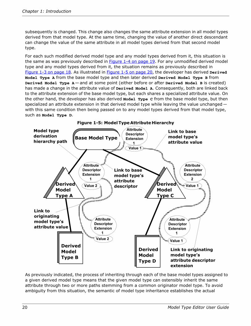
The attribute hierarchy actually consists of both of the preceding situations in combination. Figure 1-5 on page 20 hints at the complexity that exists when multiple model types are derived from a common base model type, and the attribute extension of one of these derived model types
Base Model Type
Derived Model Type A
Links to base model type’s attribute descriptor extension
Model type derivation hierarchy
path
Link to originating model type’s attribute value
AttributeDescriptorExtension 1Value_1
AttributeDescriptorExtension 1Value_2
AttributeDescriptorExtension 1Value_2
Derived Model Type B
20 Model Type Editor User Guide
Chapter 1: Introduction
subsequently is changed. This change also changes the same attribute extension in all model types derived from that model type. At the same time, changing the value of another direct descendant can change the value of the same attribute in all model types derived from that second model type.
For each such modified derived model type and any model types derived from it, this situation is the same as was previously described in Figure 1-4 on page 19. For any unmodified derived model type and any model types derived from it, the situation remains as previously described in Figure 1-3 on page 18. As illustrated in Figure 1-5 on page 20, the developer has derived Derived Model Type A from the base model type and then later derived Derived Model Type B from Derived Model Type A—and at some point (either before or after Derived Model B is created) has made a change in the attribute value of Derived Model A. Consequently, both are linked back to the attribute extension of the base model type, but each shares a specialized attribute value. On the other hand, the developer has also derived Model Type C from the base model type, but then specialized an attribute extension in that derived model type while leaving the value unchanged— with this same condition then being passed on to any model types derived from that model type, such as Model Type D.
Figure 1-5: Model Type Attribute Hierarchy
As previously indicated, the process of inheriting through each of the base model types assigned to a given derived model type means that the given model type can ostensibly inherit the same attribute through two or more paths stemming from a common originator model type. To avoid ambiguity from this situation, the semantic of model type inheritance establishes the actual
Base Model Type
Derived Model Type A
Derived Model Type B
Link to base model type’s attribute descriptor
Model type derivation hierarchy path
Link to originating model type’s attribute value
Derived Model Type C
Derived Model Type D
Link to base model type’s attribute value
Link to originating model type’s attribute descriptor extension
AttributeDescriptorExtension 1
AttributeDescriptorExtension 2
AttributeDescriptorExtension 1
AttributeDescriptorExtension 1
AttributeDescriptorExtension 1
Value 1
Value 1
Value 1
Value 2
Value 2

Model Type Inheritance
Model Type Editor User Guide 21
inheritance path in accordance with a precedence order of model type ranking. Each model type has an initial inheritance path from the model on which it was originally based, with the value of this path having a rank of 1. If additional base model types are added to any derived model type, the inheritance path through the added base model type is given a rank of 2; the next one to be added would be given a rank of 3, and so on.
Figure 1-6 illustrates how this precedence of the inheritance path is established.
Figure 1-6: Precedence of Inheritance Path by Base Model Type Ranking
In the illustrated case, Model Types A and B were derived from a common base model type, both inheriting Attribute A, which is given a rank of 1 in both cases. Model Type C subsequently was derived from Model Type A, inheriting Attribute A from that parent. Derived Model Type B was later added as another base model type for Derived Model Type C. Derived Model Type C therefore has an inheritance path to Attribute A of the originating Base Model Type through both of Derived Model Types A and B, with the rank of the path through Model Type A, its first parent, being 1, and the rank through Model Type B, its second parent, being 2. Since inheritance is established by precedence of the lowest ranking value, Derived Model Type C therefore inherits that attribute through Derived Model Type A, its lowest-ranking base model type. The MTE not only identifies the natural order of precedence for all base model types for a given model type but also lets you rearrange that order as desired, by changing the natural precedence assignments. This change would put Derived Model Type C in the same condition it would have
Base Model Type
Derived Model Type A
Derivation from Model Type A
(Rank = 1)
Derivation from Model Type B
(Rank = 2)
Derivation from Base Model Type
(Rank = 1)
Derivation from Base Model Type
(Rank = 1)
Derived Model Type B
Derived Model Type C
Attribute A
Attribute A
Attribute A
Attribute A
22 Model Type Editor User Guide
Chapter 1: Introduction
had if it had originally been derived from Model Type B and then had Model Type A added as a second base model type.
Simplification of Hierarchy by “Attribute Collapsing”
To prevent further complexity, the program includes a feature that weeds out duplications. If you modify an attribute extension or a default value such that the new extension or value is equivalent to the originator model type’s corresponding attribute extension or default value, the database will in fact discard the changed attribute extension or default value, substituting the identical extension or value as if they were inherited. The model type in which you make that change (as well as any of its descendent model types) from that time on will inherit the original attribute extension or default value from the originator model type— and will inherit any subsequent change in either. This process is called “attribute collapsing.” Its function is to keep the attribute hierarchy as sparse as possible.
One exception to attribute collapsing, which became effective with SPECTRUM Release 4.0, is that this process does not take place for default values if the attribute descriptor has its Shared flag set.
Refer to “Using the MTE Dialog Boxes” on page 39, and specifically to “Model Type Migration” on page 71; “Editing Attributes” on page 71; and “Using the Edit Menu to Alter Attribute Characteristics” on page 75, for more information on model type attributes, editing and inheritance. Also, refer to the SPECTRUM Concepts Guide for more information.

23
Chapter 2: Using the MTE
This chapter describes procedures to help you start the MTE and use it to create, remove, and modify model types in your database.
Getting Started
The MTE is run as a program separate from SPECTRUM, in the X Window System™ environment.
The background colors and fonts for MTE windows are set in the mte file in the Spectrum/app-defaults directory or in your .Xdefaults file. For more information, refer to “Default MTE Resource File” on page 179 and/or to “Redefining MTE Resources” on page 179
The mte file is compiled specifically for the system platform being used, such as a Sun SPARCstation™ or a Silicon Graphics IRIX™ platform. The MTE is installed in the SS-Tools directory (along with dbtool, SSdbload, and other related programs) but must be called from the directory which contains your SPECTRUM database (normally, Spectrum/SS). The examples in this publication assume that all installed files remain in their nominal locations, as established by the default Install program, and that you have not made changes in your PATH statement so as to call these programs from other locations. If you have made such changes or moved files to different locations for any reason, you must modify the procedures described here as necessary to provide equivalent calling functions.
Note: You must have read/write permission in order to run the MTE.
Caution: Do not edit a database currently being used by SpectroSERVER, another MTE, or any other process. Corruption of the database can occur. A file named .VNMDB.LOCK is created when a program or process accesses the SPECTRUM database. This file is a safety feature that protects the database, restricting access to one program or process at a time. The need to remove the .VNMDB.LOCK file is very rare, because the .VNMDB.LOCK file normally is removed when a program is shutdown,. Use an appropriate UNIX command to display current processes and confirm that there are no processes using the database. These processes can include SpectroSERVER, reports, dbtool, SSdbsave, SSdbload and mte. Removing the .VNMDB.LOCK file creates an opportunity for two processes to access the database, which can corrupt the database. Refer to SPECTRUM Database Management.
Do not permit editing across multiple databases by more than one user using the same developer ID. This practice creates conflicts with handles for GIB views and Inference Handlers

24 Model Type Editor User Guide
Chapter 2: Using the MTE
which can only be corrected by manually re-entering the conflicting model types, attributes, etc. If two separate databases are being used, users must ensure that the database files are not being modified with different developer IDs.
Warning messages occur in pop-up windows in most MTE procedures if you attempt to do something that cannot be done or which would result in a nonexportable file. If you disable the generation of the latter warning messages, you will not be warned when you perform changes that are not exportable. In all such cases, you will have the option of continuing or canceling the changes.
A pop-up message will occur in both instances when warnings are enabled and disabled.
If you are registered as a developer with Aprisma Management Technologies, Inc., any new model types and relations that you create during an MTE session will have your developer ID. If you are not a registered developer, model types and relations that you create will have the default developer ID, designated as DF. Refer to “Activating Your Developer ID” on page 11 for information on loading your developer information file, which contains your Developer ID.
Protecting Your Database
The Model Type Editor is a powerful tool. Using it involves some risk to your database, including: accidental destruction of needed model types, inappropriate setting of attribute flags, and creation of more than one database with different model type derivations. Adoption of the following suggestions will help you preserve your database.
• Avoid editing the database that you use to model your network until absolutely necessary. Test your model type edits on a test database first.
• Restrict the use of the MTE to individuals who are familiar with the long-term plans for your model type derivation scheme. This can help prevent unnecessary modifications to the database.
• Use the database management utilities (such as SSdbsave and SSdbload) provided with SpectroSERVER for creating copies of the database. You may get unpredictable results if you use another method. Refer to SPECTRUM Database Management for information on using these utilities.
Starting the Model Type Editor
Before starting the MTE the first time, you should have loaded the appropriate Developer ID information, which can be done only once. Refer to “Activating Your Developer ID” on page 11 and/or to SPECTRUM Database Management for information on loading your developer information file.
Caution: Database access is limited to only one application at a time. When the MTE (or dbtool) is in use, all other applications (including SpectroSERVER) must be denied access. While Aprisma-developed programs automatically lock out other Aprisma products, corruption of the database can occur if this caution is ignored or bypassed by any third-party application programs.

Starting the Model Type Editor
Model Type Editor User Guide 25
There are two convenient ways to start the MTE. The recommended, preferred way is to select it in the SPECTRUM Control Panel’s Configuration View see Figure 2-1 on page 26, as described in the following paragraph. This approach takes advantage of setups initiated by the Control Panel application to ensure correct operation. The other way is to type the appropriate command-line instructions in any X-term window see Figure 2-2 on page 28; use of this alternative approach requires that certain prerequisite system conditions exist, however.
Starting the MTE from the Control Panel
To start the SPECTRUM Control Panel, proceed as follows:
1. Verify that there are no other programs running that can access the database.
2. Start the SPECTRUM Control Panel (refer to Figure 2-1 on page 26.)
3. Confirm that the status message at the bottom of the Control Panel is colored blue and reads INACTIVE and that the left-most button in the top row reads Start SpectroSERVER rather than Stop SpectroSERVER. If otherwise, click that button to stop the server and wait until the Status message reads INACTIVE.)

26 Model Type Editor User Guide
Chapter 2: Using the MTE
Figure 2-1: Starting MTE from the SPECTRUM Control Panel
4. Click on the Configure button.
The label on the Configure button becomes grayed out and the system displays a SPECTRUM Configuration Panel view, overlaying the regular Control Panel view.
5. On the resulting Control Configuration View, click on the Model Type Editor button.
The label on the Model Type Editor button becomes grayed out, the Status readout at the bottom of the primary Control Panel becomes yellow with the message changing to EDITING, and various notes then appear in the scroll field just above that readout, reporting on the status of the called program. The MTE’s Model Type View screen (see Figure 2-3 on page 31) appears on your screen within less than a minute, depending on the size of your database.
Note: Previous versions of the MTE loaded the associated MTE views and the entire database, requiring as much as ten minutes. The revised program only loads as much as is needed for the specific view being presented to the screen, which is accomplished within seconds. This same
c. Click on Model Type Editor button.
b. Click on Configure button.
User Seabury@bicycle: Aprisma Managment Technologies
ExitFreeze Scroll Status: INACTIVE
SPECTRUM Control Panel
Cancel
SPECTRUM Configuration Panel
ECEditor
SPECTRUM Control Panel
File Control Configure Tools Help?
Scheduler
ConfigureSave
RestoreSpectroGRAPH
Process Control Database Administration Administration
Server
When SPECTRUM Configuration Panel view appears …
As MTE loads, Aprisma’s licensing notice and start-up information scrolls up through message display area on main Control Panel.
General
SpectroGRAPH
Configuration
Model Type Editor
General Configuration
StartSpectroSERVER Save
Restore
Configure
Scheduler
a. Make sure that status of SpectroSERVER is INACTIVE; if it is RUNNING, click on the Stop SpectroSERVER button.

Starting the Model Type Editor
Model Type Editor User Guide 27
procedure occurs each time you change the view on the MTE, thereby dividing the loading time among the different views.
Starting the MTE from the Command Line
To start the MTE, proceed as follows:
1. Using the Unix ps command or other means, verify that there are no other programs running that can access the database.
2. Start the windowing system applicable for your computer system (refer to Figure 2-2 on page 28).
3. Change to the directory containing the SpectroSERVER database you want to modify (normally, the Spectrum/SS directory in whatever directory you installed SPECTRUM into). The directory should contain the database files, consisting of a number of paired *.db and *.ix files. together with a number of miscellaneous files and supporting subdirectories.
4. At the system prompt, enter the following command:
../SS-Tools/mte
As the MTE loads, the system displays the MTE Restricted Rights Notice followed by several messages similar to the following:
Primary Developer info: prefix=DF, id=ffff0000, name=DEFAULTnext mt handle =ffff0001next attr handle=ffff000anext rel handle =ffff0000

28 Model Type Editor User Guide
Chapter 2: Using the MTE
Figure 2-2: Starting MTE from the Command Line
After the database loads, the Model Type View appears, showing the model type Root (the highest level) in the Model Type Name field. If these normal results do not occur, proceed as follows:
a. Using the Unix ps command or other means, verify that the MTE is the only program accessing the database. If any other programs that can access the database are running, shut those programs down.
b. There are rare occasions when the database is not closed properly by a process using the database (for example, when the Control Panel is shut down with a Control-C command). In such cases, a lock file named .VNMDB.LOCK, created in the database directory when the database was opened, remains in effect rather than being removed from the system as part of the normal shutdown process. If the MTE (or any other
/bin/csh
/Spectrum/SS
***NOTICE***NOTICE***NOTICE***NOTICE***NOTICE***NOTICE***NOTICE***Primary Developer info:
prefix = DF, id = ffff0000, name = DEFAULTnext mt handle = ffff0001next attr handle = ffff0001next rel handle = ffff0001
../SS-Tools/mtesetenv $USERFILESEARCHPATH=../app-defaults/%N
/bin/csh
/bin/csh
/Spectrum/SS
MTE’s start-up information shows system status (values given here reflect initial setup, before the Developer ID is loaded).
***NOTICE***NOTICE***NOTICE***NOTICE***NOTICE***NOTICE***NOTICE***Primary Developer info:
prefix = DF, id = ffff0000, name = DEFAULTnext mt handle = ffff0001next attr handle = ffff0001next rel handle = ffff0001
In any X-term window …
../SS-Tools/mtesetenv $USERFILESEARCHPATH=../app-defaults/%N
/bin/csh
Make sure that the SpectroSERVER is not currently running, and then call the mte program from the SS-Tools directory.

Navigating in the MTE
Model Type Editor User Guide 29
program) finds this lock file when it tries to open the database, the program produces a message similar to the following and immediately shuts down:
If you see this message, verify that no other process is using the database and then remove that lock file from the system by accessing the database directory and entering the following command or the equivalent:
rm .VNMDB.LOCK
Restart the MTE; it should now start properly.
5. If desired, resize the Model Type View window to any convenient wider width or deeper depth so as to minimize the need to use the scroll bars in the various window fields.
Navigating in the MTE
As stated earlier, model types are arranged in a hierarchy (refer to “Model Types, Models, Attributes, Relations, and Rules” on page 12). Most MTE operations begin by moving around in this hierarchy of model types, selecting a model type, and then making changes to its attributes or relations—or adding new attributes, relations, or meta-rules. For the sake of simplicity and clarity, the procedures in this publication presume that you are using the normal mouse, but many of the various maneuvers can be accomplished in a variety of ways, as described in the following paragraphs. You can navigate through the MTE hierarchy by using menu selections, keyboard commands, mouse shortcuts, or any combination of these techniques.
Navigating Using the Mouse and Menus
To select a model type, relation, etc., from one of the views, move the mouse cursor to that entry and single click with the left mouse button. You can then select any option from one of the pull-down menus, such as Examine Attributes from the File menu. In this publication, an instruction telling you to make such a selection is worded such as “Select the File > Examine Attributes option (meaning: pull down the File menu and select the Examine Attributes option). Note that there are two ways to do this:
• You can click on the File label in the menu bar, causing the associated menu to appear. You can then move the cursor to the desired option label (Examine Attributes) and click on that option to select the designated function.
• You can place the cursor on the File label in the menu bar and press down the left mouse key, causing the menu to appear, and then— still holding down the left mouse key— slide the
Database already locked by: seabury, by process: /chipmunk/Spectrum/SS/
SpectroSERVER, by process ID: 3933,
on network node: chipmunk, which started at: 03/07/1996_9:39:30.
MTE shutting downMTE shut down complete

30 Model Type Editor User Guide
Chapter 2: Using the MTE
cursor down the menu list to the desired option label (Examine Attributes) and then release the button to confirm that selection.
The result is the same, in either case, and the way you choose is your personal preference.
When you select an option that is not permitted, the MTE displays a dialog box advising you of the operational error. If you select the File > Examine > Derived option from the Model Type View without first selecting an object in the Derived Model Types list in the lower half of that view, for example, the MTE will display a dialog box displaying the error message “Must select a Derived Model Type.” As with most MTE dialog boxes, this is a modal display, and you must click on Close (or press Return on your keyboard) to get back to the previous view. You can then make whatever correction has been identified by the error message.
Unless otherwise specified, the instruction in this publication “to click on” an entry or “to single-click” an item means to move the cursor to that entry and then momentarily depress the left mouse button— or, when applicable, as described above, sliding the cursor to the desired location with the left mouse button held down and then releasing the button. This process also is sometimes referred to as “left-clicking.”
Navigating Using the Mouse Alone
In most views, navigation shortcuts are available using the mouse alone. In general, you can use the left mouse button on a function to select the associated operation or open an associated view or menu. The right mouse button, formerly used for special exit routines, has been made inoperative.
The straight-forward way to change the information being displayed or to open a new view is to select an object, pull down a menu, and click on the desired menu option. The following sequences, for example, show how you can move down through the hierarchy of model types to a desired derived type—or move up through the hierarchy to a specific base type:
To view a derived model type (see Figure 2-3 on page 31), proceed as follows:
• Click on one of the entries in the Derived Model Types field in the lower half of the Model Type View to highlight that entry.
Example: To view the MMDeveloper type, move the mouse cursor to the MMDeveloper line entry in the Derived Model Types field on the primary Model Type View and click the left mouse button to highlight that entry.
• Select the File > Examine Derived option, using either of the following methods:
• Click on the File entry in the menu bar at the top of that view to open the pull-down file menu and then click on the Examine Derived option in that menu.
or
• Alternatively, press and hold down the left mouse key while the cursor is on the File entry, slide the cursor down to the Examine Derived option, and then release the button to confirm that selection.
To view a base model type, proceed as follows:
• Click on one of the entries in the Base Model Types field in the Model Type View to highlight that entry.

Navigating in the MTE
Model Type Editor User Guide 31
• Select the File > Examine Base option, using either of the following methods:
Figure 2-3: Sequence of Normal Selection Through File Menu vs. Shortcut
• Click on the File entry in the menu bar at the top of that view to open the pull-down file menu and then click on the Examine Base option on that men.
Model Types:
Base Model Types:
Model Type Handle:
Model Type Name:Root
10000
Model Type View
Derived Model Types:
CS EntityTypesCS ManufacturerCS ModelFragmentCS MMDeveloperCSRO commonCTAD AppDataRoot
File Edit View
CS MMDeveloper
Model Type Handle:10000
1. Click on desired model type entry in Derived Model Types list.
Result: Selected model type becomes new current model, identified in Model Type Name field, with previous model type now listed as Base Model Type and with the Derived Model Types list now identifying types that have been derived from the selected model.
*
2. Pull down File menu and click on Examine Derived option.
CS Root
CS Gen_EPI_DevCS Hub_SO_Ser3000
Model Types:
Base Model Types:
Model Type Handle:
Model Type Name:MMDeveloper
1037b
Model Type View
Derived Model Types:
3CTR 3ComTokenRing
File Edit View*
CS Root
ATCP AscomTimeplex
BOMT NotMajorAppsBOMT NotMinorApps
BOUS USRMajorAppsBOUS USRMINApp
BOUS USRModem
BSH GnBsAppDerPt
CS Root
CS Gen_EPI_DevCS Hub_SO_Ser3000
Model Types:
Base Model Types:
Model Type Handle:
Model Type Name:MMDeveloper
1037b
Model Type View
Derived Model Types:
3CTR 3ComTokenRing
File Edit View*
CS Root
ATCP AscomTimeplex
BOMT NotMajorAppsBOMT NotMinorApps
BOUS USRMajorAppsBOUS USRMINApp
BOUS USRModemBSH GnBsAppDerPt
Shortcut: Double-click on desired model type entry in Derived Model Types list.
Find -> New Model Type…
Examine ->
Set Filter…Clear Filter…
Export Model Types…Import ->
Toggle WarningsSave to Permanent CatalogExit MTE
32 Model Type Editor User Guide
Chapter 2: Using the MTE
or
• Alternatively, press and hold down the left mouse key while the cursor is on the File entry, slide the cursor down to the Examine Base option, and then release the mouse button to confirm that selection.
A shortcut capability is available for many navigation functions. As an alternative to the foregoing procedures, for example, you can double-click the desired line entry in the Derived Model Types field to immediately establish that derived type as the current model of interest (see Figure 2-3 on page 31). Alternatively, you can double-click on a line entry in the Base Model Types field to immediately establish that selected base as the current model. Similarly, double-clicking on the currently selected model type in the Model Type Name field causes the MTE to display the Attribute View for that model, exactly as if you had pulled down the File menu and selected the Examine Attributes option. Similar double-click shortcuts are available for many other functions on other MTE views, as identified where those views are discussed Figure 3-1 on page 106.
Right-mouse clicking has been made inoperative in the MTE program.
Using the Keyboard to Access Menus
The F10 function key lets you access functions from the menu bar without using the mouse. To access the menus:
1. To activate keyboard selections from the menu bar, press F10 once. This action places the program in keyboard selection mode and selects the first menu on the menu bar, which is the File menu option. Pressing F10 again takes the program out of keyboard selection mode. In addition, the keyboard selection mode is also terminated if you click the left mouse button anywhere else in the current view, in which case the view returns to normal and responds in the same way that it would have responded if the mouse activation were initiated before going into keyboard selection mode.
2. While in keyboard selection mode, pressing the applicable left and right cursor direction keys makes the cursor move left or right across the menu bar, selecting whichever menu function is next in sequence. (Before you pull down a pull-down menu, the associated pull-down menus for the selected function does not become displayed by this horizontal selection process, but the selection is indicated by activation of the switch icon for that menu selection.)
3. While in keyboard selection mode, you can activate the pull-down menu for the currently selected menu-bar function by pressing the applicable cursor-direction down key. Once you have activated any pull-down menu in this fashion, you can move up or down its menu option list by pressing the applicable up or down cursor-direction keys. This directivity is cyclic; moving up or down beyond the last selection in either direction simply moves the cursor to the selection at the opposite end of the pull-down menu.
4. Once you have activated any pull-down menu in keyboard selection mode, you can move to and select the next adjacent pull-down menu by pressing the applicable left or right cursor-direction key (and then go up or down that menu’s option list by pressing the applicable up or down cursor-direction key).
5. To pick the currently selected menu option, press Return.

Common Menu Features
Model Type Editor User Guide 33
6. To close the pull-down menu without selecting any option while in keyboard selection mode, either press Esc or else click the left mouse button anywhere in the view other than in the pull-down menu area. (If you click the left mouse button while the mouse cursor is in any pull-down menu option area, that option will be selected.)
7. When you terminate keyboard selection mode by pressing F10 a second time, the cursor moves to the first selectable item in the associated view. This is not a true selection, however—you can move the cursor sideways or up or down to the next selectable object in any given direction by pressing the applicable cursor direction keys, but pressing Return does not select the current function.
Accelerators (Keyboard Shortcuts)
Certain pull-down menu options have keyboard shortcuts. These shortcuts (also called accelerators) are keyboard sequences that perform the same action you would obtain by posting the menu and picking the associated option. To use an accelerator, you click on an entry, icon, annotation, or window to select it and then press the accelerator key combination.
Accelerators use non-alphanumeric keys in combination with other keys. One such common set of accelerators, for example, is identified by an underscore that appears under specific letters in the menu bar on most views. In the Model Type View, the underlined characters are the initial letters at the beginning of each menu name (File, Edit, View). For Unix systems, this means that holding down the Alt key and the unshifted letter key will open the associated menu. Pressing Alt+f, for example, opens the File menu; you can then move up and down or sideways to adjoining menus by using the cursor direction keys, as previously described.
These accelerators are optional features, controlled by the .starrc file. This file is usually found either in the same directory as your .Xdefaults file, or in the /Spectrum/app-defaults directory. The xterm implementation of the Exceed utility does not provide for this feature, however, and NT users must select the menus and their options with the mouse.
Some common representations (and their meanings) for the non-alphanumeric keys used in accelerator sequences described in this publication are as follows:
If an accelerator requires you to press the Alt key and the f function key simultaneously, this publication describes that operation as Alt+ f (to open the pull-down File menu); similarly, Alt+F7 means to hold down the Alt key and press the F7 special function key (to grasp the window in which the cursor is located).
Common Menu Features
The MTE menus are accessible using techniques similar to those you use for SPECTRUM menus, as previously described. The actual menu bar titles and the contents of each pull-down menu change
Shift either Shift key
Ctrl Control key
Alt Alt key
34 Model Type Editor User Guide
Chapter 2: Using the MTE
depending on the view. This section provides some general information about the pull-down menus and their contents.
File
Varies from view to view.
Edit
Provides the Copy and Paste options. These features operate in the same manner in the MTE as in SPECTRUM.
Copy
Copy is used to copy a group of characters. Select the characters or field to be copied, then select the Edit > Copy menu option. The program then stores the copied items in the paste buffer until they become overwritten by a subsequent Copy operation.
Paste
To Paste the items from the paste buffer into a field, single-click in the field using the left mouse button and then execute the Edit > Paste menu option.
View
Available in the Model Type View and Relation View. The View menu provides a means of navigating to the Relation View from the Model Type View. (There is a View menu on the Relation View, but it currently has no functional entries.)
Using Multiple Selection Techniques
MTE multiple selection is supported by the Motif Extended Select feature. The MTE multiple selection techniques do not operate in the same way as those used in SpectroGRAPH. Three combinations of keyboard and/or mouse operations can be used to define multiple selections in several MTE views:
• Drag Select – All the items that the mouse pointer is dragged over as a single group while the left button is held depressed are selected.
• Click and hold the left mouse button.
• Drag the mouse pointer up or down a list of items.
Example: To obtain a copy of a sequence of attributes, you can drag-select the desired sequence of entries in the Attribute Names field on the Attribute View and then activate the Edit > Copy function or the Ctrl+Ins keyboard shortcut.
• Mouse + Control (Ctrl) key – Selects multiple individual items.
• Hold down the Control (Ctrl) key and single-click with the left mouse button on each listed item you wish to select as a single group.
• If you change your mind or discover an erroneous selection, you can also deselect individual items by re-clicking on the highlighted entry, which then becomes unhighlighted.
• Mouse + Shift key – Selects multiple consecutive items from a list.

Closing Out of MTE Operations
Model Type Editor User Guide 35
• Hold the Shift key and single-click with the left mouse button on any item (either the first or last item in the sequence).
• Select a second item by single-clicking on it, still holding the Shift key. All items between and including the two items are selected.
• If you want to change the number of items selected, you can adjust the span of consecutive selections by repressing the Shift key and selecting a new item to either increases or decreases the span of items.
You can use these multiple selection techniques with the following views and lists:
Closing Out of MTE Operations
In past versions of the MTE, if you decided not to save any inprocess changes, you could exit from any view (but not modal dialog boxes) by clicking the right mouse button. While this feature was designed in as a convenience, it became clear that novice users could do this accidentally and be unaware that he/she had lost all changes made during preceding operations. The current version of MTE (since SPECTRUM 6.0) guards against this accidental loss by removing the right-click functionality of the mouse but substituting a special Save Changes dialog box, which forces the user to make a conscious decision as to whether any inprocess changes should be saved — and forces this same decision for each different view, hence for each phase of the process.
When you activate the MTE, the Model Type View initially is focused on the Root model type by default, with its basic top-level derivatives listed as the derived model types. From this point on, your system is operating with a Working Catalog cache area that gets created by activation of the MTE and remains in effect for the length of the working session. Any changes you make will be made with respect to replicas of the actual model types, with these replicas being stored in this Working Catalog. (This arrangement, introduced with SPECTRUM 4.0, significantly enhances the operating speed of the MTE, as the program only calls into the Working Catalog whatever database elements are called for during the working session, rather than copying the entire model-type catalog from the database.)
When you are working with a specific element in a model type, such as an attribute, the system creates a still smaller temporary cache for the data items involved with that specific operation. You thus can make changes in this component storage area without affecting the information stored in the Working Catalog, until you are satisfied with these changes.
View Field
Model Type View Base Model TypeEdit Export List
Attribute Edit View Attribute NamesAttribute Groups
Relation View Relation Names
Rule View Rules
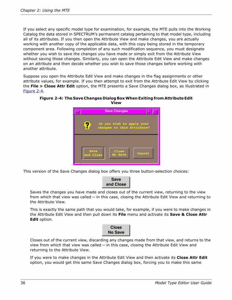
36 Model Type Editor User Guide
Chapter 2: Using the MTE
If you select any specific model type for examination, for example, the MTE pulls into the Working Catalog the data stored in SPECTRUM’s permanent catalog pertaining to that model type, including all of its attributes. If you then open the Attribute View and make changes, you are actually working with another copy of the applicable data, with this copy being stored in the temporary component area. Following completion of any such modification sequence, you must designate whether you wish to save the changes you have made or simply exit from the Attribute View without saving those changes. Similarly, you can open the Attribute Edit View and make changes on an attribute and then decide whether you wish to save those changes before working with another attribute.
Suppose you open the Attribute Edit View and make changes in the flag assignments or other attribute values, for example. If you then attempt to exit from the Attribute Edit View by clicking the File > Close Attr Edit option, the MTE presents a Save Changes dialog box, as illustrated in Figure 2-4.
Figure 2-4: The Save Changes Dialog Box When Exiting from Attribute Edit View
This version of the Save Changes dialog box offers you three button-selection choices:
Saves the changes you have made and closes out of the current view, returning to the view from which that view was called— in this case, closing the Attribute Edit View and returning to the Attribute View.
This is exactly the same path that you would take, for example, if you were to make changes in the Attribute Edit View and then pull down its File menu and activate its Save & Close Attr Edit option.
Closes out of the current view, discarding any changes made from that view, and returns to the view from which that view was called— in this case, closing the Attribute Edit View and returning to the Attribute View.
If you were to make changes in the Attribute Edit View and then activate its Close Attr Edit option, you would get this same Save Changes dialog box, forcing you to make this same
Save and Close
CloseNo Save
Do you wish to apply your
changes to the Working Catalog?
Save Changes
Saveand Close
CloseCancel
Do you wish to apply yourchanges to this Attribute?
No Save

Closing Out of MTE Operations
Model Type Editor User Guide 37
decision. This is an extra safety feature, designed to guarantee that you will not discard inprocess changes by mistake.
Terminates the exit process itself, returning to the view in which you have initiated changes, so that you can modify those changes or initiate others.
After you have made a series of one or more such changes to one or more attributes, and you then attempt to exit from the Attribute View by clicking the File > Close Attributes option in that view, the MTE presents a slightly different version of the Save Changes dialog box, as illustrated in Figure 2-5.
Figure 2-5: The Save Changes Dialog Box When Exiting from Attribute View
This version of the Save Changes dialog box offers you three similar choices:
Saves all changes you have made and then closes out of the current view (the Attribute View) in which those changes were effected, returning to the Model Type View.
This is exactly the same path that you would take, for example, if you were to make changes in the Attribute View, pull down the File menu on that view, and activate its Save All Changes option.
Note that the changes, when saved, are being saved in the “Working Catalog,” which is a storage area that becomes enabled when you activate the MTE and into which the relevant data is fetched from the actual SPECTRUM database.
Closes out of the current view, discarding any changes made from that view, and returns to the view from which that view was called.
If you were to make changes in any attribute and then pull down the Attribute View’s File menu and activate its Close Attribute option, you would get this same Save Changes dialog box, forcing you to make this same decision. As before, this is an extra safety feature, designed to guarantee that you will not discard inprocess changes by mistake.
Cancel
Save and Close
Close
Do you wish to apply your
changes to the Working Catalog?
Save Changes
Saveand Close Close Cancel
Do you wish to apply yourchanges to the Working Catalog?

38 Model Type Editor User Guide
Chapter 2: Using the MTE
Terminates the exit process itself, returning to the Attribute View so that you can modify your changes or initiate others.
When you have completed all desired changes (additions, deletions, and/or modifications) and have returned to the Model Type View, finally, clicking on the File > Exit MTE option produces still another version of the Save Changes dialog box, as shown in Figure 2-6.
Figure 2-6: The Save Changes Dialog Box When Exiting from Model Type View
This version of the Save Changes dialog box offers you three choices, again, but on a more permanent basis, as this is the final operation of the work session, and any changes saved at this point will go into your system database as permanent entries:
Note: Any saved changes in this case are saved in the Permanent Catalog, becoming part of the SPECTRUM database for the host system. Subsequent calls to that database for the saved model type will use the changed data, which will now be the permanent version.
Saves the changes you have made and shuts down the MTE program itself, returning to the SPECTRUM Control Panel or to the X-term window from which the MTE was originally started.
This is exactly the same path that you would take, for example, if you were to make changes on any MTE application view, return to the Model Type View, pull down the File menu and activate its Save to Permanent Catalog option.
Shuts down the MTE, discarding any changes made during the current work session, and returns to the SPECTRUM Control Panel or to the X-term window from which the MTE was originally started.
If you were to make changes in any attribute (or other model type element) and then pull down the Model Type View’s File menu and activate its Exit MTE option, you would get this same Save Changes dialog box, forcing you to make this same decision. As before, this is an extra safety feature, designed to guarantee that you will not discard inprocess changes by mistake.
Cancel
Saveand Quit
Quit
Do you wish to apply your
changes to the Working Catalog?
Save Changes
Saveand Quit Quit Cancel
Do you wish to apply yourchanges to the Permanent Catalog?

Using the MTE Dialog Boxes
Model Type Editor User Guide 39
Terminates the exit process itself, returning to the Model Type View (with any previously saved changes still stored in the Working Catalog).
Using the MTE Dialog Boxes
Dialog boxes are used throughout the MTE. All dialog boxes used in the MTE have the following characteristics:
• MTE dialog boxes are modal; they must be operated upon before other functions can be performed. Keep this in mind whenever you find that clicking on a view does not seem to have any effect; the reason may be that the view you are clicking on, or another one, is covering a modal dialog box that needs to be acted upon before anything else can be done.
• In the special case of error or alert messages, the MTE dialog boxes only have one operator control, marked either Continue or Close. The function of this box is to halt all activity until the user clicks on that button (or presses Return), thereby confirming that the user has read the associated error message.
• All other MTE dialog boxes let you make selections, perform edits, or provide entries; in all cases, these actions that you perform within the dialog box take effect only when you click on an OK button in that dialog box (or press Return) to confirm completion of the desired operation setup.
• Those MTE dialog buttons that let you perform an action, as described in the preceding statement, also include either a Close button or a Cancel button. If you decide for any reason that you do not wish to perform the operation associated with the given dialog box, you can click on that termination button to exit from the inprocess setup without making any changes.
Most of the dialog boxes used in the MTE relate to specific tasks and are described in the following sections pertaining to those task. The immediately following section, however, describes three dialog boxes which perform functions that can be applied in several situations while using the MTE. These functions are the Find Model Type, Set Filter, and Cut List boxes.
Using the Find Model Type Dialog Box
The Find Model Type dialog box helps you find a specific model type in the model type hierarchy, even when you are unsure where it is located or the exact spelling of its name. The Find Model Type dialog box lets you search for a specific model type name or handle—or lets you enter a pattern and list all model type names that contain that pattern. Once a desired model type is located, the dialog box lets you open the Model Type View for that model type.
The search performed by the Find Model Type feature is not case-sensitive. The search finds all occurrences of the user-entered search pattern, using both uppercase and lowercase characters. For example, if you initiate a search using “Lan” as the search pattern, the resulting scroll list can contain such model types as LAN_802_3, LAN_802_5, and LAN—whatever model types in your database have a name that includes the letters “lan” in that sequence. You can then select one model type from the resulting list and navigate to that specific model type.
Cancel

40 Model Type Editor User Guide
Chapter 2: Using the MTE
Finding Specific Model Types
To find a specific model type, proceed as follows:
1. With a Model Type View open, pull down the File menu and select Find > Model Type. The Find Model Type dialog box will appear, as shown in Figure 2-7 on page 41.
2. Click your mouse pointer in the Name or Handle block to activate that field, and then enter the model type name or character-string search pattern you want to find. This entry can be as specific as the exact full name of the desired model type or as general as any minimum number of characters known to be included in that name.
Finding Model Types Containing a Specific Pattern in Their Names
To search for all model types having names that contain a specific character-string pattern, proceed as follows:

Using the MTE Dialog Boxes
Model Type Editor User Guide 41
Figure 2-7: The Find Model Type Dialog Box
a. Select a character-string pattern that you suspect is contained within the name of the model type you are trying to locate, and enter that pattern into the Name or Handle field. (The pattern search utility is not case-sensitive.)
b. Click on the Apply button to begin the search. The scroll list that appears in the upper list block as a result of the search shows all model types found that match the given search pattern, with the entry in the Name or Handle field changing to whatever applies for the first entry in that list. (If there are no models found in the database that match the pattern, a dialog box appears stating either “Model type does not exist”— if the
Model Type Names:
Find Model Type
Name or Handle
Model Type Handles
Ok CloseApply
1. Click in the Name or Handle field and enter the character string for a specific model type name, handle, or pattern you want the Model Type Editor to look for (search is not case-sensitive.)
2. Select Apply to search for the entered pattern.
4. After selecting a model type from the results of the search, select Ok to navigate to the model type or select Close to quit the operation without making any changes.
3. After you enter a character string and click on the Apply button, the system lists in this text field all model types it finds in the database which have that same character string as part of their name. You can then select any one of the listed items and click on Ok to designate that type as the model type of interest.
42 Model Type Editor User Guide
Chapter 2: Using the MTE
entered string was in the format of a name entry— or else “No model types match that pattern” if the entered string was in the format of a handle.)
c. In the upper scroll list, select the particular model type you were looking for by moving the mouse cursor to that entry and then double-clicking on that entry (or, alternatively, by clicking on the name once to select that entry and then clicking on the Ok button). The full model type name automatically appears in the pattern field.
The dialog box disappears and the program returns to the Model Type View, which changes to identify:
• The selected model type, designated in the Model Type Name field.
• The corresponding handle, designated in the Model Type Handle field.
• All previous-generation base model types (model types from which any attributes, relations, or meta-rules in this model type have been derived), listed in the Base Model Types scroll list.
• All next-generation database-stored models derived from the selected model type, listed in the Derived Model Types scroll list.
If you decide at any time before initiating the navigation change that you do not want to change from the currently selected model type, press the Cancel button to exit from the Find Model Type dialog box and return to the Model Type View with the original designations unchanged.
Using the Set Filter Dialog Boxes
The MTE has two Set Filter dialog boxes, both called from the pull-down File menu. When you pull down the File menu in the Model Type View and select the Set Filter… function, the MTE displays the Set Model Type Filter dialog box. If you pull down the File menu on the Attribute View, however, the corresponding option is named Set Filter Name/ID, and its activation calls the Set Attributes Filter dialog box, discussed later in this section. Both dialog boxes are used to enter an applicable filter to restrict the number of items to be displayed in a given view.
In the case of the model type filter, entries in the Derived Model Types scroll list in the lower half of the Model Type View will be restricted to whichever derived model types have names (including the initial developer-identification component) that comply with the character-string coding that has been set into the filter. When the model type filter is applied, that scroll list displays only items matching the character string established as the filter. The database itself is not affected by the filter; only the display presentation is changed. As long as the filter value remains in effect, the MTE continues to apply the filter on a view-by-view and level-by-level basis.
This condition can lead to confusion. If you apply a certain filter value to restrict the number of derived model types displayed in the Derived Model Types scroll list, for example, and you then double-click one of the entries in the Base Model Types list to change the focus of the Model Type View, the result may well be an empty Derived Model Types list, because you may have applied a restriction that is valid for one or more “child” types but for none of the “parent” types.
Caution: To avoid being confused or misled by residual readout conditions, you should develop the habit of clearing the model type filter as soon as you have determined whatever relationships you want to know—and of clearing the model type filter at the start of each
Using the MTE Dialog Boxes
Model Type Editor User Guide 43
operation you perform with the MTE, so as to ensure that no residual filter setting remains in effect.
The option just below the Set Filter… option on the File menu is the Clr Filter… function. Activation of this option clears the current filter setting.
Applying the Model Type Filter
Perform the following steps to set the model type filter:
1. Open the Model Type View.
2. Pull down the File menu and click on the Set Filter… option to access the Set Filter dialog box Figure 2-8 on page 44.
3. Single-click with the left mouse button in the Name field to enable text entry, and then enter the name of the desired model type to specify an individual model type—or enter a character string representing any partial component of the name if you want to reduce the number of displayed entries to just those model types that have names matching that search string. The following expressions can be used to define a filter:
Any character string — Display all entries that contain (whether in model type, model-type group, or developer ID) the string as typed, with each character matching itself in sequence. The search is not case-sensitive: upper-, lower-, and mixed-case characters are displayed—thus, setting “lan” as the target string would produce a list of all model types whose names or developer identifications included any of “lan,” “Lan,” “lAn,” “LAn,” “lAN,” “LaN,” or “LAN” anywhere in the overall combined character string. (Keep in mind that all model-type names, including the developer prefix, can contain only alphanumerics.)

44 Model Type Editor User Guide
Chapter 2: Using the MTE
Figure 2-8: Set Filter Dialog Box
. (period) — The period matches any character except the newline. character.
Any non-bracketed expression beginning with a caret (^) — Represents a match for any entry that begins with the entered character string (hence, part or all of the prefixed developer ID).
Any non-bracketed expression ending with a dollar sign ($) — Represents a match for any entry that ends with the entered character string (hence, the end of the model type name).
Any set of characters enclosed in brackets ([]) — Represents a one-character expression that matches any one of the characters included in the set. For example, “[lan]” matches any one of “l” or “a” or “n” (whereas “lan” would match any of “lan,” “Lan,” “lAn,” “LAn,” “lAN,” “LaN,” or “LAN”). An exception occurs if the caret character is the first character in the set, however, in which case the match is for any single character that is not included in the set. For example, “[^lan]” would match any single lower-case character except “l” or “a” or “n”— and also, since the search is not case sensitive, would match any upper-case character except “L” or “A” or “N.” In addition, a range of characters can be indicated with a hyphen. For example, “[a-z]” would match any alphabetic character— lower-case or upper-case. This approach is most effectively used in conjunction with unprotected characters, thereby representing optional characters in the overall string.
Any one-character expression (including bracket-enclosed sets) followed by an asterisk (*) — Represents a match for zero or more occurrences of the entered character string. For example, “[a-z]*” matches zero or more lower-case or upper-case letters.
Set Filter
If you change your mind for any reason, click on Cancel button to exit from filter-setting function and return to Model Type View without setting filter.
2. After designating desired filter pattern, click on Ok button to set that entered value into model type filter.
Result: Derived Model Types scroll list on Model Type View becomes limited to specific model type(s) matching entered filter pattern.
Name
CancelOk
1. Click in text field to enable entry and then type in desired character pattern corresponding to desired model type or group of model types, in accordance with coding described in Table 2-1 on page 45.

Using the MTE Dialog Boxes
Model Type Editor User Guide 45
A one-character expression followed by a plus sign (+) — Represents a match for one or more occurrences of the entered character string. For example, “[a-z]+” matches one or more lower-case or upper-case letters.
A one-character expression followed by a question mark (?) — Represents a match for zero or one occurrence in the string. For example, “la?n” will match any of “lan” or “ln” or “Lan” or “LAn” or “LAN” or “lAn” or “laN” or “lAN” or “Ln” or “LN” or “lN.”
Concatenation of expression strings — Represents an expression matching the corresponding concatenation of strings. For example, “[A-Z][0-9]*” will accept as a match any (including zero) combination of letters (in any combination of upper and lower case) and numerals—but no symbols.
4. Select the Ok button in the dialog box to apply the model type filter.
If you decide for any reason that you do not want to apply the model type filter, select the Cancel button on the dialog box to exit from this setup and return to the Model Type View, with the filter setting remaining unchanged.
Table 2-1: Examples of MTE Filter Search-String Options
Entry Code Resulting Display Restrictions for Derived Model Types Scroll List in Model Type View
802 Displays all entries that contain the character string “802” in exactly that same sequence, anywhere in the combined developer prefix and model type name entry, for any number of times.
HUB Displays all entries that contain the letters “hub” in that same sequence anywhere in the combined developer prefix and model type name entry (whether in upper-, lower-, or mixed-case).
Hub$ Displays all model type name entries ending with the letters “hub” in that same sequence, whether in upper-, lower-, or mixed-case.
^hub Displays all entries beginning with the string “hub” (in upper-, lower-, or mixed-case combinations) as the start of the developer prefix.
<character>. Displays all entries containing the designated single character (except for the newline character) preceding a period.
5 or 5. Displays all prefix/name entries containing a “5” character.
[f-j] Displays all prefix/name entries that contain at least one alphabetic character from the range of “f” through “j” in the normal alphabetic sequence.
[4-8] Displays all entries that contain at least one numeric character from the range of “4” through “8” in the normal numeric sequence anywhere in the combined prefix/name entry.
[drz] Displays all entries that contain at least one of the alphabetic characters “d” or “r” or “z” (in any order or case combination) anywhere in the combined prefix/name entry.
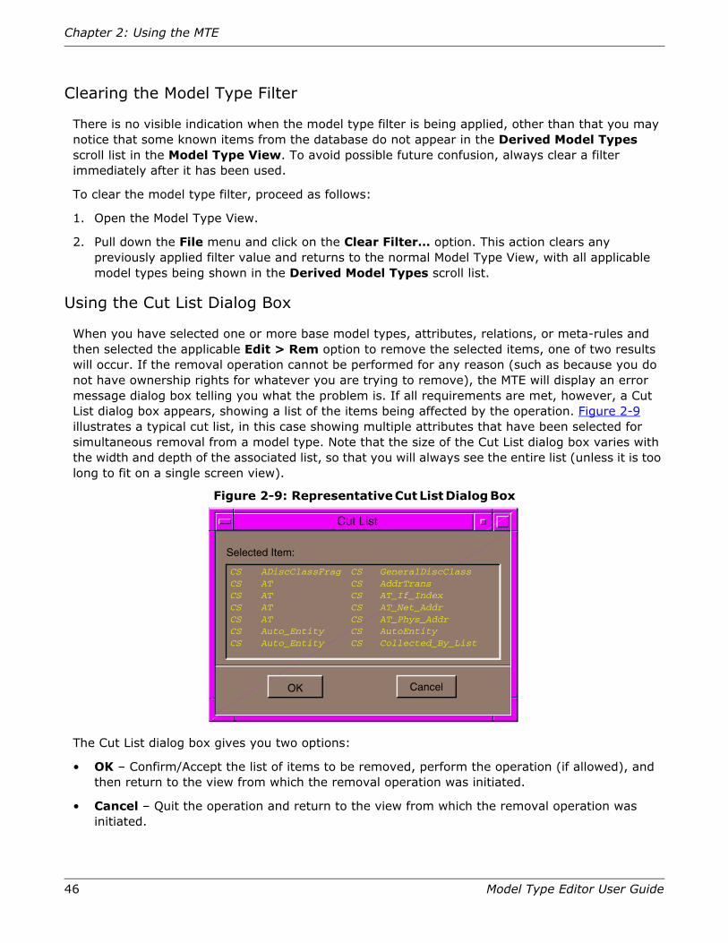
46 Model Type Editor User Guide
Chapter 2: Using the MTE
Clearing the Model Type Filter
There is no visible indication when the model type filter is being applied, other than that you may notice that some known items from the database do not appear in the Derived Model Types scroll list in the Model Type View. To avoid possible future confusion, always clear a filter immediately after it has been used.
To clear the model type filter, proceed as follows:
1. Open the Model Type View.
2. Pull down the File menu and click on the Clear Filter… option. This action clears any previously applied filter value and returns to the normal Model Type View, with all applicable model types being shown in the Derived Model Types scroll list.
Using the Cut List Dialog Box
When you have selected one or more base model types, attributes, relations, or meta-rules and then selected the applicable Edit > Rem option to remove the selected items, one of two results will occur. If the removal operation cannot be performed for any reason (such as because you do not have ownership rights for whatever you are trying to remove), the MTE will display an error message dialog box telling you what the problem is. If all requirements are met, however, a Cut List dialog box appears, showing a list of the items being affected by the operation. Figure 2-9 illustrates a typical cut list, in this case showing multiple attributes that have been selected for simultaneous removal from a model type. Note that the size of the Cut List dialog box varies with the width and depth of the associated list, so that you will always see the entire list (unless it is too long to fit on a single screen view).
Figure 2-9: Representative Cut List Dialog Box
The Cut List dialog box gives you two options:
• OK – Confirm/Accept the list of items to be removed, perform the operation (if allowed), and then return to the view from which the removal operation was initiated.
• Cancel – Quit the operation and return to the view from which the removal operation was initiated.
Do you wish to apply your
changes to the Working Catalog?
Cut List
OK Cancel
CS ADiscClassFrag CS GeneralDiscClassCS AT CS AddrTransCS AT CS AT_If_IndexCS AT CS AT_Net_AddrCS AT CS AT_Phys_AddrCS Auto_Entity CS AutoEntityCS Auto_Entity CS Collected_By_List
Selected Item:

Creating a Model Type
Model Type Editor User Guide 47
Successful completion of the selected operation after you have clicked on the OK button depends on whether or not you have access rights to the items selected for removal— that is, whether those objects were created under the same Developer ID code currently loaded into your database. If you do not have access rights, the system will instead display a modal Error List dialog box, as illustrated in Figure 2-10 on page 47, which lists the items for which you do not have access rights (and which you therefore cannot remove). The only option provided to you by this box is to click on the Close button (or press Return), thereby canceling out of the disallowed operation.
Figure 2-10: Representative Error List Dialog Box
Creating a Model Type
When you want to represent a new device or some other entity that is not currently defined as a model type in the SPECTRUM database, you must create a new model type.
The MTE simplifies this task by letting you create a new model type that inherits attributes from existing model types, which you can define as its base model types. The overall process, then, must begin by first determining what attributes you want for your new model type. Next, you must identify base model types from which the new model type can inherit these attributes, or as many of them as possible. Once you have completed this preparation, the procedure is to derive the new model type from that base model type which has the most of the attributes you want your model type to inherit, then add other base model types that can provide other desired attributes. If necessary, you can then manually add any remaining attributes that are not already provided by existing model types in your database. You can usually use existing model types to provide most of the desired attributes, but you may have to add some unique attributes.
Preparation
To identify the model types you want to use as base model types, you can use the Model Type View to navigate through the model type hierarchy to specific model types and then use the Attribute View to determine what attributes each such existing model type has (refer to Step 2 of the following procedure). Continue this process until you have identified which existing model type contains most of the attributes needed for the new model type—and which other model types can provide some or all of whatever other attributes are needed for your new model type.
Do you wish to apply your
changes to the Working Catalog?
Error List
Close
CS ADiscClassFrag CS GeneralDiscClassUser may not remove another vendor’s attributCS AT CS AddrTransUser may not remove another vendor’s attributCS AT CS AT_If_IndexUser may not remove another vendor’s attributCS AT CS AT_Net_AddrUser may not remove another vendor’s attributCS AT CS AT_Phys_AddrUser may not remove another vendor’s attribut
Errors:

48 Model Type Editor User Guide
Chapter 2: Using the MTE
During this preparatory process, keep the following guidelines in mind:
• You can only use derivable model types as base model types (that is, the Derivable flag in the Attribute View must be set).
• You should use as few base model types as possible, so as to keep the hierarchy simple.
• You should try to avoid adding base model types that do not provide a significant contribution to the model type being created— or which contain a significant number of unneeded attributes. Since you cannot remove inherited attributes, ignoring this guideline could quickly add an excessive number of attributes, wasting storage space and perhaps affecting performance.
Creation of New Model Type
To create the new model type, proceed as follows:
Note: The following procedure outlines the basic steps for creating a new model type from scratch. In actual practice, however, the best starting point generally is the GnSNMPAppDerPt model type, which contains that basic attributes and intelligence normally required for Spectrum applications. For further details on GnSNMPAppDerPt and its related model types, refer to the Generic SNMP Device Management User Guide and Toolkit.
1. Open the Model Type View.
2. Navigate through the model types in your hierarchy, examining the attributes for each model type by using the File > Examine > Attributes option. Find a derivable base model type (one that has the Derivable flag set in its Attribute View) that has most of the attributes you need for your new model type.
3. Create a new model type, based on the selected model type, as follows:
a. With the selected base model in the Model Type Name field (that is, designated as the current model type), pull down the File menu and click on the New Model Type option. The New Model Type dialog box appears, as shown in Figure 2-11 on page 48.
Figure 2-11: The New Model Type Dialog Box
b. In the New Model Type dialog box, click the mouse cursor in the Name field and enter a desired name (maximum of 128 characters, consisting of any combination of letters, numbers,underscore characters (_), or dash characters (-), but no other punctuation
New Model Type
Ok
Name
Cancel

Creating a Model Type
Model Type Editor User Guide 49
marks or symbols) for the new model type. (The MTE will automatically assign a unique handle value, based on the currently loaded Developer ID, as follows:
You can subsequently use this handle (or any part of it) as a filter pattern for the Find Model Type… function (refer to “Using the Find Model Type Dialog Box” on page 39).
c. Click on the Ok button to confirm the new model type name.
If your entry was not acceptable, the program will display an error message reporting that fact, as illustrated in Figure 2-12 on page 49. Clicking on the Close button returns you to the Model Type View, canceling out of the New Model dialog box, and you can try again, this time using a correct name configuration.
Figure 2-12: Error Message Produced by Attempt to Create New Model with Unacceptable Name
If the base model type you selected is not derivable, the program displays a different error message informing you of that fact, as illustrated in Figure 2-13 on page 50. Clicking on the Close button returns you to the Model Type View, canceling out of the New Model generation dialog box. You can then try again, this time selecting an appropriate base model type (that is, one that has its Derivable flag set on its Attribute View).
Structural Makeup of the Model Type Handle
Developer ID Prefix
(4 hexadecimal characters, starting in position 1,
Unique sequence number,
f f f f 0 0 0 0
Dev. ID Sequence #
never repeated for same Developer ID
starting in position 5)
(1 to 4 hexadecimal characters,
leading zeros not shown)
1 0 2 d 7
Error
Only numbers, letters, and underscores allowed in Name.
Close
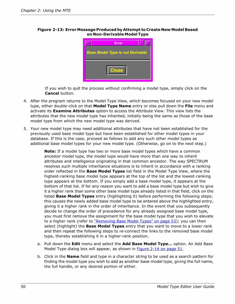
50 Model Type Editor User Guide
Chapter 2: Using the MTE
Figure 2-13: Error Message Produced by Attempt to Create New Model Based on Non-Derivable Model Type
If you wish to quit the process without confirming a model type, simply click on the Cancel button.
4. After the program returns to the Model Type View, which becomes focused on your new model type, either double-click on that Model Type Name entry or else pull down the File menu and activate its Examine Attributes option to access the Attribute View. This view lists the attributes that the new model type has inherited, initially being the same as those of the base model type from which the new model type was derived.
5. Your new model type may need additional attributes that have not been established for the previously used base model type but have been established for other model types in your database. If this is the case, proceed as follows to add any such other model types as additional base model types for your new model type. (Otherwise, go on to the next step.)
Note: If a model type has two or more base model types which have a common ancestor model type, the model type would have more than one way to inherit attributes and intelligence originating in that common ancestor. The way SPECTRUM resolves such multiple inheritance situations is to inherit in accordance with a ranking order reflected in the Base Model Types list field in the Model Type View, where the highest-ranking base model type appears at the top of the list and the lowest-ranking type appears at the bottom. If you simply add a base model type, it appears at the bottom of that list. If for any reason you want to add a base model type but wish to give it a higher rank than some other base model type already listed in that field, click on the listed Base Model Types entry (highlighting it) before performing the following steps; this causes the newly added base model type to be entered above the highlighted entry, giving it a higher rank in the order of inheritance. In the event that you subsequently decide to change the order of precedence for any already assigned base model type, you must first remove the assignment for the base model type that you wish to elevate to a higher rank (refer to “Removing Base Model Types” on page 53); you can then select (highlight) the Base Model Types entry that you want to move to a lower rank and then repeat the following steps to re-connect the links to the removed base model type, thereby establishing it in a higher-rank position.
a. Pull down the Edit menu and select the Add Base Model Type… option. An Add Base Model Type dialog box will appear, as shown in Figure 2-14 on page 51.
b. Click in the Name field and type in a character string to be used as a search pattern for finding the model type you wish to add as another base model type, giving the full name, the full handle, or any desired portion of either.
Error
Close
Base Model Type is not Derivable

Creating a Model Type
Model Type Editor User Guide 51
c. Click on the Apply button (or press the Return key) to initiate the search.
Figure 2-14: Using the Add Base Model Type Dialog Box
d. When the results of the search appear in the Model Types scroll list in the upper portion of the dialog box, find and click on the entry identifying the model type you want to add as another base model type. That entry will become highlighted, and the full identification will appear in the Name field as a replacement for the previously entered search string.
e. Click on the Ok button to confirm your selection and initiate the process of adding the selected model type as an additional base model type for the current model type.
f. If you wish to add other model types as additional base model types for the current model type, repeat steps a through e as applicable for each such model type.
Add Base Model Type
Ok CloseApply
Name
Model Types
1. Click in the Name field and enter the character string for a specific model type name, handle, or pattern you want the Model Type Editor to look for (search is not case-sensitive.)
2. Click on Apply to search for the entered pattern.
4. After selecting a model type from the results of the search, select Ok to add that model type as a base model type or select Close to quit the operation.
3. After you enter a character string and click on the Apply button, the system lists in this text field all model types it finds in the database that have that same character string as part of their name. You can then select any one of the listed items and click on Ok to designate that type as the model type of interest.

52 Model Type Editor User Guide
Chapter 2: Using the MTE
Note: In addition to the basic “core” model types occupying the higher levels of the model type hierarchy, Aprisma has developed several semi-specialized model types providing the intelligence and attributes generally found to be needed by a majority of known applications. These include GnSNMPAppDerPt, GnChassisDerPt, GnDevIODerPt, GnRelayDerPt., GnSNMPSubDerPt, and a number of more-specialized derivation-point model types. In addition, you very likely will want to add one or more base model types providing access to specialized MIB attributes and intelligence. The recommended approach for the latter is to create a stock of MIB-data model types in your database, each one containing the specific intelligence and attributes pertaining to a specific MIB. To do this, first create a new model type based on GnSNMPMibDerPt, name it in such a way as to identify it with respect to the specific MIB with which it is to be associated, and then import that MIB into that model type (see “Importing a MIB” on page 162). You can then add that MIB-specific model type as a base model type whenever you need to have the modeling intelligence of that particular MIB in your model type.
6. If you need to add one or more new attributes that you do not find available as inheritable through some other base model type, you can add such features manually by following the procedure in “Adding Attributes to a Model Type” on page 56.
7. As a final phase of the development process, you need to provide a defining value for a key attribute so that SpectroGRAPH will recognize the model that becomes generated by your model type. This operation is called “mapping” the model type to the MIB. Proceed as follows:
a. In the Attribute View for your new model type (and referring to the MIB you imported as necessary), identify some attribute that is external, integer, non-table, and mandatory.
• “External” attributes are preceded by an asterisk at the left end of the Attribute Names scroll list; they also can be identified by examination of the associated Attribute Edit View, where the External Attribute Description flag will be set.
• The upper button in the Type field in the Attribute Edit View presents any one of the integer-based type names (Integer, Enumeration, Time Ticks, Counter, or Gauge).
• The lower button in the Type field in the Attribute Edit View reads Single Value rather than List of Values.
• “Mandatory” attributes are so designated in the MIB.
b. In the Attribute View, note the Attr ID value for the selected attribute satisfying the requirements listed above.
c. Move to the line entry for the default_attr attribute in the Attribute Names scroll list.
d. Double-click on the default 0 (zero) entry in the associated Values scroll list.
e. When the Alter Value dialog box appears, highlight the default value in the New Value field, type in the previously noted Attribute ID value as a substitute entry, and then click on the Ok button.
f. When the Attribute View data reappears on your screen, confirm that the previously selected Attribute ID value now is listed as the Value entry for the default_attr attribute of your new model type.

Creating a Model Type
Model Type Editor User Guide 53
g. If the newly created model type is a final model type, to be used for creating SpectroGRAPH models, make sure that the Instantiable flag in the Attribute View is set (depressed).
h. Click on the Attribute View’s File > Close Attributes option and then click on the Save and Close option in the resulting Save Changes dialog box in order to save your attribute changes to the Working Catalog.
i. In the Model Type View, activate the File > Save to Permanent Catalog option—or, if you have no other MTE operations to perform at this time, click on the File > Exit MTE option and then click on the Save and Quit option in the resulting Save Changes dialog box in order to save your new model type to the Permanent Catalog.
j. Perform whatever Gib Editor operations are needed to complete your new model type.
Removing Base Model Types
You cannot remove inherited attributes (or intelligence) from a model type. Instead, you must break the hierarchal link between the current model type and the base model type in which the undesirable attribute originated. This process is called removing the base model type and is accomplished by means of an Edit > Rem Base Model Types… option in the Model Type View, as follows:
Note: While you can remove more than one base model type at a time from a “current” model type of interest, you cannot remove the last remaining base model type from a model type that is itself a base model type for one or more other model types. In order to break such a connection, you must first navigate to the derived model type(s) and use the following procedure to remove the model type of interest as a base model type with respect to the derived model type(s). You can then navigate back to the model type of interest and remove its last remaining model type.
1. In the Model Type View, click on the Derived Model Types and Base Model Types fields as applicable to navigate through the hierarchy until the Model Type Name field is set to the model type from which you wish to remove one or more base model types.
2. Select (highlight) in the Base Model Types list one or more base model types that you wish to remove from the current model type. (To select a single entry, click on the entry name with the left mouse button. To select multiple entries, hold down the Control key while you select each successive entry.)
3. Select the Edit > Rem Base Model Types… option to initiate the removal of the link between the current model type and the selected base model type(s). The program displays a Cut List dialog box listing the selected base model types.
4. Click on the OK button of the Cut List dialog box to confirm that you wish to remove the links to the listed base model types. The program will then return to the Model Type View for the current model type, with the removed base model types no longer appearing in the Base Model Types scroll list.
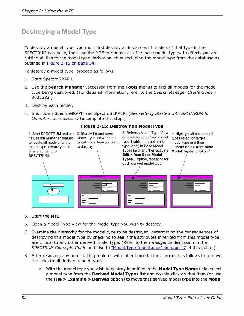
54 Model Type Editor User Guide
Chapter 2: Using the MTE
Destroying a Model Type
To destroy a model type, you must first destroy all instances of models of that type in the SPECTRUM database, then use the MTE to remove all of its base model types. In effect, you are cutting all ties to the model type derivation, thus excluding the model type from the database as outlined in Figure 2-15 on page 54.
To destroy a model type, proceed as follows:
1. Start SpectroGRAPH.
2. Use the Search Manager (accessed from the Tools menu) to find all models for the model type being destroyed. (For detailed information, refer to the Search Manager User’s Guide - 9032383.)
3. Destroy each model.
4. Shut down SpectroGRAPH and SpectroSERVER. (See Getting Started with SPECTRUM for Operators as necessary to complete this step.)
Figure 2-15: Destroying a Model Type
5. Start the MTE.
6. Open a Model Type View for the model type you wish to destroy.
7. Examine the hierarchy for the model type to be destroyed, determining the consequences of destroying this model type by checking to see if the attributes inherited from this model type are critical to any other derived model type. (Refer to the Intelligence discussion in the SPECTRUM Concepts Guide and also to “Model Type Inheritance” on page 17 of this guide.)
8. After resolving any predictable problems with inheritance factors, proceed as follows to remove the links to all derived model types.
a. With the model type you wish to destroy identified in the Model Type Name field, select a model type from the Derived Model Types list and double-click on that item (or use the File > Examine > Derived option) to move that derived model type into the Model
4 Highlight all base model types listed for target model type and then activate Edit > Rem Base Model Types… option.*
1 Start SPECTRUM and use its Search Manager feature to locate all models for the model type. Destroy each one, and then quit SPECTRUM.
2 Start MTE and open Model Type View for the target model type you want to destroy.
3 Refocus Model Type View on each listed derived model type, highlight target model type (only) in Base Model Types field, and then activate Edit > Rem Base Model Types… option, repeating for each derived model type.

Adding or Removing Attributes
Model Type Editor User Guide 55
Type Name field, with the model type you wish to destroy moving into the Base Model Types list.
b. In the Base Model Types list, select the entry for the model type you wish to destroy and then activate the Edit > Rem Base Model Type… option to remove the link between the model type being destroyed and its derived model type.
The system responds by returning the entry for the model type being destroyed to the Model Type Name field, with all readouts being the same as at the beginning of step a, except that the unlinked model type no longer is listed as an entry in the Derived Model Types field.
c. Repeat 4a and 4b for each successive entry in the Derived Model Types list, until all links between the model type being destroyed and all of its derived model types have been removed.
9. Remove all base model types from the model type to be destroyed.
a. With the model type being destroyed in the Model Type Name field, select a base model type from the Base Model Types list and then use the Rem Base Model Type… option from the Edit menu to remove the link between the base model type and the model type being destroyed. If you did not successfully remove the links to all derived model types, the system will abort this operation, displaying an error message, as illustrated in Figure 2-16.
Figure 2-16: Error Message When Target Model Type Has Derived Model Types
b. Repeat Step 9a until all links between the model type being destroyed and its base model types have been removed. Severing the link to its last base model type removes the model type from the model type derivation, moving the entry for the last-selected base model type to the Model Type Name field of the Model Type View.
Adding or Removing Attributes
You can add or remove attributes from a model type either directly or indirectly.
• You can directly add new attributes to a model type by using the Attribute View > File > New Attribute… function.
• You can directly remove attributes from a model type or one of its base model types by using the Attribute View > Edit > Rem Attributes… function.
Do you wish to apply your
Error List
<BaseModelType> Delete all derived model types before deleting a Model Type
Close
Errors:

56 Model Type Editor User Guide
Chapter 2: Using the MTE
• You can change the base model types for the current model type, thereby indirectly changing the inherited attributes, using Model Type View.
Adding Attributes to a Model Type
To create a new attribute, using existing SPECTRUM intelligence, and then add the new attribute to an existing model type, perform the following steps:
1. Locate the model type to which you wish to add the new attribute(s). You can use the File > Find > Model Type option, or you can examine model type derivations in the Model Type View.
2. Open a Model Type View for the model type to which you wish to add one or more attributes (with that model type named in the Model Type Name field).
3. Double-click on the Model Type Name entry (or select and activate the Examine > Attributes option from the File menu) to open the Attribute View for the chosen model type.
4. Pull down the File menu and activate the New Attribute option to open the Attribute Edit View.
Note: If you add an attribute to a model type you do not own, you will not be able to export that attribute and model type later.
If the model type to which you are attempting to add a new attribute was created under some other Developer ID than the one currently loaded into your database, the MTE displays a warning message dialog box, as illustrated in Figure 2-17 on page 56. If you do not care about not being able to export this model type or the about-to-be-created attribute in the future, simply click on the OK button (or press Return) to continue. If you expect that you may want to export this model type or attribute in the future, however, you should click on the Cancel button to abort this operation and then create a new model type under your own Developer ID, as described in “Creating a Model Type” on page 47.
Figure 2-17: Error Message Displayed If You Do Not Own Model Type
If you have modification rights to the current model type, instead of displaying the just-described warning message, the MTE presents the Attribute Edit View, with all values set to an initial default value, as illustrated in Figure 2-18 on page 57. When adding a new attribute, this view constitutes a template for attribute information fields. For details on setting those controls for new attributes, or changing those things which can be changed for existing attributes, refer to “The Attribute Edit View” on page 121.
Do you wish to apply your
Non-Owner Warning
You are not the owner of this modeltype.You will not be able to export this modeltype and attribute later.
Are you sure you want to add a new attribute?
OK Cancel

Adding or Removing Attributes
Model Type Editor User Guide 57
Caution: If you change flag settings of Aprisma-developed/shipped model types or other developer-supplied model types, SPECTRUM’s automatic migration is not supported. Automatic migration, which occurs during database upgrades, applies to model type attributes, relations, meta-rules, extensions, and descriptors.
Note: Currently, editing another developer’s attribute extension or another developer’s model type is not guaranteed to survive the next upgrade. Any of these changes should be noted by the user as they may need to re-apply the changes manually after upgrading to the next version release. Refer to “Model Type Inheritance” on page 17 for more information.
5. To save the newly created or edited attribute, pull down the File menu and activate the Save & Close Attr Edit option.
Figure 2-18: Initial Default Attribute Edit View When Adding a New Attribute
Successful completion of this action returns you to the underlying Attribute View, which now will show your newly created attribute in the Attribute Name field, using the format shown in Figure 2-19 on page 58. This same full name, together with the associated unique attribute handle, henceforth will appear in the Find Attribute dialog box (see Figure 2-24 on page 62) if a search is made for any character string that is included as any part of this full name.

58 Model Type Editor User Guide
Chapter 2: Using the MTE
Figure 2-19: Structural Makeup of the Full Attribute Name
If you have made an error in entering or selecting the applicable data, the MTE will not complete this saving operation but instead will display an applicable dialog box to inform you of the error. Figure 2-20, for example, illustrates the dialog box that MTE produces if you entered a name for a new attribute that is a duplicate of a name that has already been created under the same Developer ID.
Figure 2-20: Error Message Displayed If Selected Attribute Name Already Used
You will receive an error message dialog box produced if your name entry contains unacceptable characters (only numbers, letters, underscores, and dashes are allowed). The MTE displays error dialog boxes for a variety of discovered shortcomings, in each case identifying the problem and returning you to the applicable view. You can make the appropriate corrections so that your changes can be saved, or you can decide to exit from the program without making any changes at this time.
If you decide for any reason not to save your changes, you can exit from the program without saving them by clicking on the File > Close Attr Edit option and then clicking on the Close No Save option in the resulting Save Changes dialog box.
Removing Attributes
When you remove an attribute, it is removed from every derived model type in the derivative path below the model type you are working with.
Caution: Do not remove attributes that are needed by a derived model type. Check all derived model types to ensure that the attribute you are removing from the derivative path is not needed. If necessary, you can provide an alternate path via a different base model type, or else recreate the attribute at the derived model type level.
CS PwrSupply_12 SPTR PhaselockLoop
Developer ID Prefix for originating model type
Model type in which attribute was originated
Attribute Name
Developer ID Prefix for attribute
(8 characters, starting in position 1)
(128 characters, starting in position 9)
(8 characters, starting in position 137)
(128 characters, starting in position 145)
Save Attr
Close
Duplicate attribute name

Adding or Removing Attributes
Model Type Editor User Guide 59
Note: You cannot remove certain attributes, including inherited attributes or attributes in model types created by another developer. When attributes falling in either of these categories are selected as part of a multiple select, the MTE removes only the attributes that can be removed; it then displays an Error List dialog box listing those attributes that were not destroyed.
To remove an attribute from a model type, proceed as follows:
1. Open a Model Type View and navigate through the model type hierarchy until the model type containing the attribute you want to remove is the entry in the Model Type Name field.
2. Verify the attribute being removed is not critical to a derived model type.
3. Double-click on the model type entry in the Model Type Name field (or activate the File > Examine > Attributes option) to open the Attribute View, as illustrated in Figure 2-21 on page 59.
4. From the Attribute Names scroll list, select the attribute(s) you want to remove (for multiple selections, hold down the Control key and click on each entry you want to select).
5. With the files selected (highlighted), select the Edit > Rem Attributes… option to remove the selected attribute(s).
Figure 2-21: The Attribute View
The MTE begins the removal operation by displaying a cut list dialog box listing each attribute that is to be removed, as illustrated in Figure 2-22 on page 60. Since this is a modal box, you must click on the Close button (or press Return) to confirm that you really intend to remove these listed attributes. The MTE then initiates the actual removal process.
Attribute View
File Edit
Derivable
Required
Instantiable
Unique
Visible
No Destroy
For Model Type:Entity Types
Attribute Names
<empty> 1154e EntityTypes
Values Attr ID Attr Group
<no group>EntityTypesRootRootRootRootRoot<no group>Root
11aef1154b11b4711b411007c110b411b3d11ae3111f1
0NONE.00002104.00.00
ntityTypes CS condition_assertionntityTypes CS EntityTypesntityTypes CS Normal_View_TypeCS Root CS createdateCS Root CS createtimeCS Root CS Model_StateCS Root CS model_verifyCS Root CS PollingMultiplierCS Root CS RootCS Root CS Version_Number
View*

60 Model Type Editor User Guide
Chapter 2: Using the MTE
Figure 2-22: Representative Cut List Dialog Box
If the MTE program determines that one or more of the attributes you are trying to remove cannot be removed by you for any reason, the MTE displays a cut list error message dialog box identifying the problem, as illustrated in Figure 2-23. Since this is a modal box, you must click on the Close button (or press Return) to confirm that you have received this information; the MTE then returns you to the Attribute View, with the unremoved attributes still in place.
Figure 2-23: Error Message If Trying to Remove Attribute You Do Not Own
If this situation occurs with a multiple selection, the MTE deletes the attributes that you can delete but lists the ones that you cannot, together with the reason. In this case, you should exercise care in exiting from the Attribute View and/or from the MTE program, as the removal of those attributes that you can remove does not become final unless you select the applicable Save option in each case.
6. Even though the successfully removed attributes are gone from the Attribute View scroll list, any such removal is not actually completed until you confirm that removal. To do this, you must select the File > Save All Changes option and then click on the Save and Close button in the resulting Save Changes dialog box. The MTE then stores the confirmed change in the Working Catalog and returns you to the Model Type View.
7. Even though the preceding step confirms the removal of the successfully removed attributes from the Working Catalog, this change lasts only for the duration of the current work session unless you subsequently confirm these same changes to the Permanent Catalog. To make the change(s) permanent, either at this time or at the end of the total work session, you must
Cut List
OK Cancel
CS ADiscClassFrag CS GeneralDiscClassCS AT CS AddrTransCS AT CS AT_If_IndexCS AT CS AT_Net_AddrCS AT CS AT_Phys_AddrCS Auto_Entity CS AutoEntityCS Auto_Entity CS Collected_By_List
Selected Item:
Error List
<ModelType> <Attribute> User may not remove another vendor’s attribute.
Close
Errors:

Adding or Removing Attributes
Model Type Editor User Guide 61
select the Model Type View’s File > Save to Permanent Catalog option and then click on the Save and Close option in the resulting Save Changes dialog box.
Using the Find Attribute Dialog Box
The Find Attribute dialog box helps you find a specific attribute in the model type hierarchy, even when you are unsure where it is located or the exact spelling of its name. The Find Attribute dialog box lets you search for a specific attribute name or handle—or lets you enter a character string as a pattern. The MTE will then list all attribute names or handles that contain that pattern, with the first entry in that list being highlighted. Once a desired attribute is located, you can open the Attribute View for the current model type, with the scroll list in that view restricted to the specific attribute.
The search performed by the Find Attribute… feature is not case-sensitive. The search finds all occurrences of the user-entered search pattern, using both uppercase and lowercase characters (note that this means a full search of the entire data base, which takes an appreciable interval of time). For example, if you initiate a search using lan as the search pattern, the resulting scroll list will identify every attribute that includes lan or Lan or LAN as part of its name. If you type in a portion of the attribute handle, conversely, the search will list every attribute in the database that includes that search pattern as part of its handle.
Either way, you can then select any one entry from the resulting list. If the attribute you select happens to be included in the current model type (whatever model type is identified in the Model Type Name field of the Model Type View), you can then move to an Attribute View that is restricted to that one attribute. If that attribute is not included in the current model type, the MTE will instead open an Attribute View for the first model type in the database that does include that attribute. Either way, you can either examine the attribute details shown in the Attribute View or move to an Attribute Edit View of the given attribute.
Finding a Specific Attribute
To find a specific attribute, proceed as follows:
1. With a Model Type View open, select the File > Find > Attribute… option. The Find Attribute dialog box appears, as shown in Figure 2-24 on page 62.

62 Model Type Editor User Guide
Chapter 2: Using the MTE
Figure 2-24: The Find Attribute Dialog Box
2. Click your mouse pointer in the Name or Handle block to activate that field, and then enter any of the following:
• The attribute name.
• The full attribute handle.
• Any partial character-string search pattern that you think will be contained by the name or handle of the attribute that you want to find.
Finding Attributes Containing a Specific Pattern
To search for all occurrences of a specific character-string pattern, proceed as follows:
a. Select a character-string pattern you suspect is contained within the name of the attribute you are trying to locate, and enter that pattern into the Name or Handle field. (The pattern search utility is not case-sensitive.)
Attribute Name
Find Attribute
Name or Handle
Attribute Handle
Ok CloseApply
1. Click in the Name or Handle field and enter the character string for a specific attribute name or handle, or any partial search pattern you want the Model Type Editor to look for (search is not case-sensitive.)
2. Select Apply to search for the entered pattern.
3. After selecting an attribute from the results of the search, select Ok to navigate to the Attribute View or select Close to quit the operation.
After you enter any character string and click on the Apply button, the system lists in this text field all attributes it finds in the database with that same character string as part of their name. You can then select any one of the listed items and click on Ok to designate that type as the attribute of interest.
This action sets the attribute filter for the selected attribute. The program then calls the Attribute View, set to that selected attribute, either for the current model type or (if the model type does not possess that attribute), for the highest-ranking model type in the hierarchy that does contain it.

Adding or Removing Attributes
Model Type Editor User Guide 63
b. Click on the Apply button to begin the search. The scroll list that appears in the upper list block as the result of that search shows all attributes found in the database that match the given search pattern, and the entry in the Name or Handle field changes to whatever exists as the first entry in that list. (If no attributes that match the given pattern are found in the database, a dialog box appears, stating “No attributes match that pattern.”)
c. In the upper scroll list, double-click on the particular attribute you were looking for (or, alternatively, click on the name once to select that entry and then click on the Ok button). The full attribute name and handle identification automatically appears in the pattern field as soon as you first highlight the entry.
When you double-click on the desired entry or click on the Ok button after selecting that entry, the dialog box disappears and the MTE displays the Attribute View, restricted to whichever attribute you selected in the Find Attribute dialog box (see Figure 2-25 on page 64).
If the selected attribute is used by whatever model type was listed in the Model Type Name field of the Model Type View when you accessed the Find Attribute dialog box, the Attribute View is for that model type, as designated in the For Model Type field. If the selected attribute does not occur in that original model type, however, the MTE shows an Attribute View for the highest-ranking model type in the hierarchy structure that does contain that attribute.
If you decide at any time before initiating this navigation change that you do not want to change to the Attribute View (for example, if all you wanted to do was find out how many attributes contained a given name or handle character string), click on the Find Attribute dialog box’s Cancel button rather than the Ok button. This action makes the MTE exit from the Find Attribute dialog box and return to the regular Attribute View, with the original designations and the attribute filter setting left unchanged.

64 Model Type Editor User Guide
Chapter 2: Using the MTE
Figure 2-25: The Attribute View, Restricted to a Specific Attribute
Using the Set Attribute Filter Dialog Boxes
The MTE has two Set Filter dialog boxes, both called from the File menu. One, as previously described, is the Set Model Type Filter dialog box, called from the Set Filter… option in the pull-down File menu on the Model Type View. If you pull down the File menu in the Attribute View, however, the corresponding option is named Set Filter Name/ID and its selection causes the MTE to display the Set Attributes Filter dialog box. Both dialog boxes are used to enter an applicable filter value so as to restrict the number of items to be displayed. When a filter is applied, only items containing a character string that matches the string established as the filter value are displayed.
The database itself is not affected by the setting of the attribute filter, but the Attribute View display becomes limited to show only those attribute names or Attribute ID values that include the character string set in the filter. If the current model type does not contain any of those attributes, then none will be displayed in the Attribute View.
Caution: To avoid being confused or misled by residual readout conditions, develop the habit of clearing the attribute filter (by activating the File > Clear Filter… option) as soon as you have determined whatever relationships you want to know—and of clearing the attribute filter at the start of each operational sequence you perform with the MTE, so as to ensure that no residual filter setting remains in effect.
Attribute ViewFile Edit
Derivable
Required
Instantiable
Unique
Visible
No Destroy
For Model Type: JBS_Rtr_NB_30
Attribute Names
5 180003 AprismaFrag
Values Attr ID Attr Group
SPTR JBS_RTR_NB_3Com SPTR Notes
View*

Adding or Removing Attributes
Model Type Editor User Guide 65
Applying the Attribute Filter
Perform the following steps to set the attribute filter:
1. Open the Attribute View for the desired model type (as designated in the Model Type Name field of the associated Model Type View).
2. Pull down the File menu and click on the Set Filter Name/ID option. The Set Attribute Filter dialog box will appear, as shown in Figure 2-26.
Figure 2-26: Set Model Type Filter and Set Attribute Filter Dialog Boxes
Single-click with the left mouse button in the Name field (or the Pattern field) to enable text entry, and then enter the character string or expression that you want to use as a filter. The following expressions can be used to define a filter:
(Blank) — Display all entries (no filter applied).
Any character string — Display all entries that contain the search string as typed, with each character matching itself, anywhere in the combination of the developer prefix and name of the model type in which the attribute originated and/or in the developer prefix and name of the attribute — or in the handle assigned to that same attribute. The search is not case-sensitive: upper-, lower, and mixed-case characters are displayed.
. (period) — The period matches any character except the newline. character.
Any non-bracketed character string beginning with a caret (^) — Represents a match for any entry that begins with the expression. (Note that this means the beginning of the developer prefix for the model type in which the attribute originated.)
Set Attribute Filter
Ok Cancel
Filter Name or ID
1. Click in text field to enable entry and then type in desired character pattern corresponding to desired attribute or group of attributes, in accordance with options described in Table 2-1 on page 45.
If you change your mind for any reason, click on Cancel button to exit from filter-setting function and return to Attribute View without setting filter.
2. After designating desired filter pattern, click on Ok button to set that entered value into attribute filter.
Result: Scroll list on Attribute View becomes limited to specific attribute(s) matching entered filter pattern.

66 Model Type Editor User Guide
Chapter 2: Using the MTE
Any non-bracketed character string ending with a dollar sign ($) — Represents a match for any entry that ends with that same character string. (Note that this means the end of the attribute handle, in this case, not the attribute name.)
Any set of characters enclosed in brackets ([]) — Represents a one-character expression that matches any one of the characters included in the set, occurring anywhere in the total combination of the originating model type’s developer prefix and name and the attribute developer prefix and name or in the attribute handle. For example, [lan] matches any one of “l” or “a” or “n” (whereas lan would match any of lan, Lan, lAn, LAn, lAN, LaN, or LAN). An exception occurs if the caret character is the first character in the set, however, in which case the match is for any single character that is not included in the set. For example, [^lan] would match any single lower-case letter except “l” or “a” or “n”— or, since the search is not case-sensitive, any single upper-case letter except “L” or “A” or “N.” In addition, a range of characters can be indicated with a hyphen. For example, [a-z] would match any lower-case or upper-case letter, while [f-h] would match any one of lower-case “f” or “g” or “h” or upper-case “L” or “G” or “H” anywhere in the entry line.
Any one-character expression (including bracket-enclosed sets) followed by an asterisk (*) — Represents a match for one or more occurrences of the entered character string. For example, [a-z]* matches one or more lower-case or upper-case letters (but not numerals or symbols). This approach can be used advantageously in conjunction with unbracketed characters to serve as wild characters in the total string. For example, acme[1-0]* would display all entries containing the string “ACME” followed by any number.
A one-character expression followed by a plus sign (+) — Represents a match for one or more occurrences of the expression. For example, [a-z]+ matches one or more lower-case or upper-case letters.
A one-character expression followed by a question mark (?) — Represents a match for zero or one occurrence in the string. For example, la?n will match any one of lan or ln or Lan or LAn or lAn or lAN or Ln or lN or LN — but not laan.
Concatenation of expression strings — Represents an expression matching the corresponding concatenation of strings. For example, [A-Z][0-9]* will accept as a match any (including zero) combination of letters or numerals (but no symbols).
3. Select the Ok button in the dialog box to apply the attribute filter.
If you decide for any reason that you do not want to apply the attribute filter, select the Cancel button on the dialog box to exit from this setup and return to the Attribute View with the filter setting being left unchanged.

Adding or Removing Attributes
Model Type Editor User Guide 67
Caution: You may inadvertently bring about a special condition if you happen to select an attribute that was originated in an “invisible” model type which was created under a different Developer ID than is currently loaded in your database. Since you do have access to the invisible model type in which the attribute was created, the MTE instead provides a list of the visible model types in which the attribute appears. You cannot remove the attribute, however, because its source remains invisible to you.
Clearing the Attribute Filter
The attribute filter becomes cleared automatically when you exit from the Attribute View and return to the Model Type View. As long as you remain in the Attribute View (and the Attribute Edit View), however, any previously applied filter pattern remains in effect, and there is no visible indication when the attribute filter is being applied, other than that you might notice some known
Table 2-2: Examples of Attribute Filter Search-String Options
EntryCode
Resulting Display Restrictions for Derived Model Types Scroll List in Model Type View
802 Displays all entries that contain the character string “802” in exactly that same sequence, for any number of times, anywhere in the total sequence of the prefix and name of the originating model type in conjunction with the prefix and name of the actual attribute or the following Attr. ID handle. You can use this approach to find a specific attribute handle.
Hub Displays all entries that contain the letters “hub” in that same sequence (whether in upper-, lower-, or mixed-case), for any number of times, anywhere in the total combination.
b3d$ Displays all entries ending with the letters “hub” in that same sequence, whether in upper-, lower-, or mixed-case. (In the case of the attribute filter, however, note that this means the end of the attribute handle, which must be a hexadecimal value.)
^SPTR Displays all entries beginning with the string “SPTR” (in any combination of upper-, lower-, or mixed-case characters) — which in the case of attribute entries means the beginning of the developer prefix of the model type in which the attribute originated.
<character>. Displays all entries that contain the single character (except for the newline character) that precedes the period anywhere in the total sequence of the prefix and name of the originating model type in conjunction with the prefix and name of the actual attribute or the following attribute handle.
5 or 5. Displays all entries containing a “5” character anywhere in the total sequence of the prefix and name of the originating model type in conjunction with the prefix and name of the actual attribute or the following attribute handle.
[f-j] Displays all entries whose total entries contain at least one alphabetic character from the range of “f” through “j” in the normal alphabetic sequence, anywhere in the total sequence of the prefix and name of the originating model type in conjunction with the prefix and name of the actual attribute or the following attribute handle.
[4-8] Displays all entries having names that contain at least one numeric character from the range of “4” through “8” in the normal numeric sequence anywhere in the total sequence of the prefix and name of the originating model type in conjunction with the prefix and name of the actual attribute or the following attribute handle.
[drz] Displays all entries having names that contain at least one of the alphabetic characters “d” or “r” or “z” (in any order) anywhere in the total sequence of the prefix and name of the originating model type in conjunction with the prefix and name of the actual attribute or the following attribute handle.

68 Model Type Editor User Guide
Chapter 2: Using the MTE
attributes do not appear in the Attribute View. To avoid possible future confusion, always clear a filter immediately after completing the operation for which it has been used.
To clear the attribute filter, proceed as follows:
1. Open the Attribute View (for any model type).
2. Pull down the File menu and click on the Clear Filter… option. Any filter value that may have been previously applied becomes cleared and the MTE returns to the normal Attribute View, with all applicable attributes for the current model type being displayed.
Using the Find Group Dialog Box
The newly added Find Group dialog box helps you find a specific attribute group even if you are unsure where it originated from or the exact spelling of its name. The Find Group dialog box, accessed from the File menu in the Model Type View, lets you search for a specific attribute group name or handle—or lets you enter a pattern and list all attribute group names that contain that pattern. Once a desired attribute group is located, the dialog box lets you focus the Model Type View on the model type from which that attribute group originates and open the Attribute View for that model type, simultaneously opening the Attribute/Group List dialog box. You can then use the latter dialog box, as discussed in “Creating and Managing an Attribute Group” on page 83 to modify the group name, remove the group, add new subgroups to that group, make that group a subgroup of some other group, or clear the group so that constituent attributes within it can be moved or removed.
The search performed by the Find Group feature is not case-sensitive. The search finds all occurrences of the user-entered search pattern, using both uppercase and lowercase characters. For example, if you initiate a search using power as the search pattern, the resulting scroll list can contain not only such attribute group names as powerTable and ctChasPowerEntry but also any applicable model-type names —whatever attribute group names in your database includes the letters p, o, w, e, and r in that exact sequence. You can then select one entry from the resulting list and navigate to that specific model type.
Finding a Specific Attribute Group
To find a specific model type, proceed as follows:
1. With Model Type View open, pull down the File menu and select Find > Groups. The Find Group dialog box will appear, as shown in Figure 2-7 on page 41.
2. Click your mouse pointer in the Name or Handle block to activate that field, and then enter the attribute group name or handle pattern you want to use as a search string. This entry can be as specific as the exact full name of the desired attribute group or handle— or as general as any minimum number of characters known to be included in that name. For example, you could type in ICMP_In_Addr_Masks_Repeats to make sure you get that specific attribute group, and only that group.
Finding Attribute Groups Having Names That Contain a Specific Pattern
To search for all occurrences of attribute groups having names that contain a specific character-string pattern, proceed as follows:

Adding or Removing Attributes
Model Type Editor User Guide 69
1. Proceed as above, but enter into the Name or Handle field a character-string pattern that you suspect is contained within the name of the attribute group you are trying to locate. (The pattern search utility is not case-sensitive.)
2. Click on the Apply button to begin the search. The scroll list that appears in the upper list block as result of the search shows all attribute groups found that contain a character string matching the entered string, with the entry in the Name or Handle field changing to the full name of the first entry in that list, consisting of five fields of data:
• The developer ID under which the model type in which that attribute group originated.
• The common name of that model type.
• The developer ID under which the attribute group was created.
• The common name of that attribute group.
• The unique handle assigned to that group by the system at the time of creation.
If no attribute group names that match the pattern you enter are found in the database, an error box reports “No attributes match that pattern.” When this occurs, you simply click on the Ok button to acknowledge the error and then try again with a corrected entry.
3. In the upper scroll list, select the particular attribute group you were looking for by moving the mouse cursor to that entry and then double-clicking on that entry (or, alternatively, by clicking on the name once to select that entry and then clicking on the Ok button). Note, as shown in Figure 2-27 on page 70, that the display is right justified, so that all you see is the handle designation at the right end, plus the trailing edge of the group’s common name, if it is long enough; you can adjust the display to show the text fields at the beginning of the entries by sliding the horizontal scroll bar to the left.

70 Model Type Editor User Guide
Chapter 2: Using the MTE
Figure 2-27: The Find Group Dialog Box
Group Names:
Find Group
Name or Handle
Group Handles
Ok CloseApply
CSGH PowerSupp_Mib CSGH compaq
0x116094f0x116094e0x11609530x11609510x1160db40x11609520x1160db60x1160db50x11609500x11609540x116095a0x11609590x0d01da0x0d01d90x0d05af
leEntryleTable
1. Click in the Name or Handle field and enter the character string for a specific attribute group name, handle, or pattern you want the Model Type Editor to look for (search is not case-sensitive.)
2. Select Apply (or press Return) to search for the entered pattern.
3. After you activate a search, the system lists in this text field all attribute groups in the database that have that same character string as part of their name or handle, with this list right-justified such that all of the handle designation at the right-hand end of the entry appears on the screen, as shown. If that identification is sufficient, you can click on a given handle and then click on Ok (or double-click the handle entry) to focus the Model Type View on the model type in which that attribute group originates — and also to open the Attribute View and Attribute/Group List dialog box to facilitate making any desired changes.
4. If you do not recognize the group by its handle, slide the lower scroll bar to the left to make the display field show the attribute group name at the left-hand end of the entry. You can then select any one of the listed items and click on Ok (or, alternatively, double-click on the name entry) to focus the Model Type View on the model type in which that group originated and also to open the Attribute View and the Attribute/Group List dialog box to facilitate making changes.
If you decide not to refocus the Model Type View, click on the Close button to exit from the Find Group function and return to Model Type View.
After the MTE completes its search of the database, your entry in the Name or Handle field is replaced by the left-justified attribute group name (formatted in same way as attribute name).

Model Type Migration
Model Type Editor User Guide 71
4. When any entry other than the first is selected (highlighted), that selected entry appears in the Name or Handle field below the scroll list. When you complete the selection by double-clicking the entry or clicking on the Ok button, the dialog box disappears and the program reassigns the Model Type View on the model type in which the selected attribute group originated, as the new model type of interest. The program then opens the Attribute View pertaining to that model type, while at the same time opening the Attribute/Group List dialog box (defaulted to the first item in the attribute group hierarchy pertaining to that particular model type). You can then use the Attribute/Group List dialog box to modify that attribute group as desired, as described in “Creating and Managing an Attribute Group” on page 83.
If you decide at any time before initiating the navigation change that you do not want to change from the currently selected model type, press the Close button to exit from the Find Group dialog box and return to the Model Type View with the original designations unchanged.
Model Type Migration
You should keep a careful record of all changes that you make with the MTE. Some changes made with the MTE are not migrated when the database is upgraded to a higher version of SPECTRUM. Specifically, if you use the MTE to change relations, meta-rules, or attributes of any Aprisma-supplied or other developer-supplied model types, those changes most likely will not survive the database upgrade and you will have to re-apply the changes manually after completing the upgrade.
Relations
Any relations that are imported with a database upgrade will overwrite previously-made changes made to those relations in the database.
Meta–Rules
You cannot remove meta-rules created by other developers (that is, under a different Develop ID). (This prevents you from accidentally removing meta-rules that might be needed by another developer’s management module.) Also, keep in mind that any meta-rules that you add before a SPECTRUM system upgrade may have to be re-added after the upgrade.
Attributes
You should keep a record of any changes to the attribute extended descriptor fields or to the values of Aprisma-supplied attributes or of attributes supplied by another developer, so that you can manually verify and re-enter those same changes with MTE after any upgrade. For a more permanent solution, you can set the Preserve Value Descriptor Flag in the Attribute Edit View to prevent your changed values from being overwritten by different values in subsequent updates—but keep in mind that this action may prevent you from receiving intended changes pertaining to the same attribute(s).
Editing Attributes
You can edit attributes in various ways, depending on what you want to change, as described in the following subsections. Before editing an attribute’s characteristics, however, you should verify

72 Model Type Editor User Guide
Chapter 2: Using the MTE
that derived model types, which inherit this attribute, will not be adversely affected by these changes.
Determination of effects on derived model types from changes in a base model type is really a function of experience. The more you use the MTE, the more familiarity you will have with the probable impacts of changes that you make.
Note: If you assign an attribute’s Group ID to another developer’s attribute, and that developer’s attribute is not distributed with the next SPECTRUM release/upgrade, the Group ID assignment for your attribute will change to <No Group>. in addition, changes you make by editing another developer’s attribute extension or another developer’s model type are not guaranteed to survive the next upgrade. You should note any such changes, as you may need to re-apply those same changes manually after upgrading to the next version release. Refer to “Model Type Inheritance” on page 17 and to the guidelines in “Altering Flag Assignments of an Attribute” on page 79, for more information.
When you add a new attribute (through the File > New Attribute … function off the Attribute View), you can select any one of 21 different Type entries (see Figure 3-10 on page 125) and you designate a Name entry that henceforth becomes the descriptive label that appears at the right-hand entry of the Attribute View scroll list for the given model type. You can also select the on/off state of seven Descriptor Flags (all of which can subsequently be examined in the Flags section of the Attribute Edit View or in the Edit Flags dialog box), whenever you examine the model type. In addition, you can select the on/off state of four Extended Flags (all of which can subsequently be examined in the Extended Flags section of the Attribute Edit View or in the Edit Flags dialog box), whenever you examine the model type (refer to Table 3-1 on page 129). In addition, you can specify the maximum length (number of bits) of the data element, the Polling Group, and the applicable entries for the OID Prefix and OID Reference values; the nature and need for these latter entries depends on which Type entry has been selected for the attribute.
Guidelines for Editing Attributes
Here are some general restrictions for editing an attribute:
• To be able to edit the on/off settings of the Descriptor Flags (those flags that appear in the Flags portion of the Attribute Edit View’s Attribute Description area or in the Alter Flags dialog box), you must be using the same Developer ID under which the attribute in question was created.
• After an attribute has been created and saved, you cannot change the Type identification of a nonnumeric attribute, as the Type button becomes locked and you cannot open the associated pull-down menu list). The exceptions to this condition are the five numeric attributes: Integer, Time Ticks, Counter, Enumeration, or Gauge for any of these, you can click on the Attribute Edit View’s Type button to reopen the pull-down menu and then select any of the other numeric types from this same group.
• After an attribute has been created and saved, you can call up the Attribute Edit View for that attribute and change the Name entry at any time (provided that you are using the Developer ID under which that attribute was created), but you will not be able to change the Name entry for any inherited attributes in other model types derived from the model type in which you originally created that attribute.
Editing Attributes
Model Type Editor User Guide 73
• You can change the Name entry only if you are working with the original model type in which that attribute first was created (and you are using the same Developer ID with which it was created.)
• Any changes you make in the Name entry for that attribute in the original model type will immediately be replicated by all the inherited versions of that same attribute in any model types derived from the original one.
Using the Attribute Edit View
The straight-forward way to edit the definition of an existing attribute is to find that attribute in a given model type, using the Attribute View, open the Attribute Edit View to make the desired changes, and then save those changes. You can do this either by making the applicable menu bar selections or by taking advantage of various shortcuts. The following procedure outlines both approaches Figure 2-28 on page 74.
1. Open a Model Type View and navigate through the model type hierarchy by clicking in the Base Model Types or Derived Model Types fields as applicable until the model type containing the attribute you want to edit is the entry in the Model Type Name field.
2. Note any derived model types and verify that your planned edit(s) will not adversely affect any of those derived model types.
3. Double-click on the entry in the Model Type Name field (or select the File > Examine > Attributes option) to open the Attribute View.

74 Model Type Editor User Guide
Chapter 2: Using the MTE
Figure 2-28: Basic Sequence for Modifying an Existing Attribute
4. In the Attribute Names scroll field in that view, double-click on the line entry for the attribute you want to edit (or click on that line entry to select it and then activate the File > Open Attribute… option) to open the Attribute Edit View.
CS Root
CS Gen_EPI_DevCS Hub_SO_Ser3000
Model Types:
Base Model Types:
Model Type Handle:
Model Type Name:MMDeveloper
1037b
Model Type View
Derived Model Types:
CISC Cisco_DevsCM 9F106_02CM LB_ModuleCM MMACPlusCS ClientAppCS Gen_EPI_Agent
File Edit View
CS Root
Attribute ViewFile Edit
Derivable
Required
Instantiable
Unique
Visible
No Destroy
For Model Type: Entity Types
Attribute Names
<empty> 1154e EntityTypes
Values Attr ID Attr Group
<no group>EntityTypesRootRootRootRootRoot<no group>Root
11aef1154b11b4711b411007c110b411b3d11ae3111f1
0NONE.00002104.00.00
ntityTypes CS condition_assert_infontityTypes CS EntityTypesntityTypes CS Normal_View_TypeCS Root CS createdateCS Root CS createtimeCS Root CS Model_StateCS Root CS model_verifyCS Root CS PollingMultiplierCS Root CS RootCS Root CS Version_Number
View
Open Attribute…
1a. With modeltype name in Model Type Name field, pull down File menu and click on its Examine Attribute option.
1b. Shortcut: Double-click on model type name entry to open Attribute View.
Examine Attributes
8. Reselect Flags or Extended Flags as desired (refer to Table 3-1 on page 129).
6. If Type is any of integer, time tics, counter, enumeration, or gauge, you can change type to any other type in the same group (all other types are locked, once saved). 7. To assign attribute to a
different group, click on Group ID button (see Figure 2-34 on page 81).
Text String
11ae6
RevisionHistoryName:
Type:
Polling Group:
OID Prefix:
OID Ref:
Attribute Extended Description
ExtendedFlags:
Flags:External
Readable
Writable
Shared
Guaranteed
Global
Memory
Database
Polled
Logged
0
Attribute Description
Group ID:
Single ValuePreserve Value
Attribute Edit View
File Edit
4b.Shortcut: Double-click Attribute Name entry to open Attribute Edit View.
3. Reselect flag settings as desired.
2. Change name of model type, as desired.
4a.Select Attribute Name entry, pull down File menu, and click on Open Attribute… to open Attribute Edit View.
*
*
*
5. Change name of attribute as desired.
9. Change entries as applicable for changed type or flag settings (as per MIB).

Editing Attributes
Model Type Editor User Guide 75
5. In the resulting Attribute Edit View, modify the fields in the view as needed. Note that you cannot change the Type field for an existing, previously saved attribute (this selection can only be made at the time that the attribute is created) and you cannot change the on/off settings for the Descriptive Flags in the Flags portion of the view unless the attribute in question was created under the same Developer ID that you are using.
6. Select the File > Save & Close Attr Edit option and then click on the Save and Close button in the resulting Save Changes dialog box to save the edited attribute.
7. Check any derived model types and determine if there are any adverse effects in those model types from changing this attribute (in which case you should make changes as necessary) or if other new attributes are needed for those model types. Refer to “Adding Attributes to a Model Type” on page 56.
Using the Edit Menu to Alter Attribute Characteristics
To edit an attribute using Edit menu options, proceed as follows:
1. Open a Model Type View and move through the model type hierarchy until the model type containing the attribute(s) to be edited is listed in the Model Type Name field.
2. Note any derived model types and verify that the planned changes will not adversely affect any of those derived model type.
Determination of effects on derived model types from changes in a base model type is really a function of experience—and essentially uses this same procedure, in order to examine the attributes of the derived model types. The more you use the MTE, the more familiarity you will have with the probable impacts of changes that you make.
3. Confirm that the model type having attribute characteristics you want to change is identified in the Model Type Name field and then double-click on that entry (or activate the File > Examine > Attributes option) to open the Attributes View.
4. In the Attribute Names scroll list on that view, click on the entry for the attribute(s) you want to edit (if selecting more than one, hold down the Control key) and then pull down the Edit menu and click on the applicable option, as listed below, for whatever it is you want to do:
• Remove Attributes see “Removing Attributes” on page 58
• Alter Value see “Altering the Value Assignment of an Attribute” on page 76
• Alter Group see “Altering the Group Assignment of an Attribute” on page 76
• Alter Flags see “Altering Flag Assignments of an Attribute” on page 79
Note: A pop-up message appears if your selection violates certain restrictions. If you have selected more than one attribute for the Alter Value… option, for example, you will get a message saying you cannot do that. If you have selected any attribute(s) created under a different Developer ID than the one you are using for the Alter Group… or Alter Flags… options, similarly, you will be told that you cannot change the group or that you can change only the Extended Flags settings.

76 Model Type Editor User Guide
Chapter 2: Using the MTE
Altering the Value Assignment of an Attribute
The Edit > Alter Value… lets you change (or create) a value assignment for any one selected attribute. You can perform this editing operation only on one attribute at a time. The change you make (designating as true or false, establishing a numerical value identifying a telephone number, etc.) depends on what the particular attribute is.
If the attribute in question is a single-valued attribute, as determined by a Single Value selection via the lower button in the Type area of the Attribute Edit View, selecting this option opens the Alter Value dialog box shown in Figure 2-29 on page 76. To make any change, simply type the desired change into the New Value text field in the Alter Value dialog box and then click on its Ok button to return to the Attribute View—or else click on the Cancel button to exit from the dialog box without making any changes.
Figure 2-29: Altering a Default Attribute Value
If the attribute in question is a multi-valued attribute, as determined by a List of Values selection via the lower button in the Type area of the Attribute Edit View when the attribute was originated (and as designated by a <List Value> entry in the Values field in the Attribute View), selecting this option opens the List Value Edit dialog box shown in Figure 2-30 on page 78. Use of that dialog box, as indicated in that figure, involves opening various other dialog boxes to enter first an appropriate OID Index value and then to enter the value to be associated with that index entry (or to change any value that has previously been created), as well as to delete a value that is no longer desired.
Altering the Group Assignment of an Attribute
The Attribute View’s Edit > Alter Group… option lets you add one or more attributes to an existing group, or move one or more attributes from a previously assigned group to a different
New Value
Alter Value
Ok Cancel
(603) 337-7205
NOTEIf the Alter Value entry field appears without scroll bars, the allowable entry is limited by the attribute type to a value that can fit in the provided area. If scroll bars appear, the field automatically becomes larger for text-string inputs and can be expanded as needed. Early versions of the MTE were subject to a maximum length limitation, but this restriction was removed in Release 5.0, and the only limitation is the impact on system performance.
1, In the New Value field, change the previous value or type in a new one, as applicable.
2, Click on Ok to confirm the new value, on Cancel to retain the previous value.

Editing Attributes
Model Type Editor User Guide 77
group (or subgroup), provided that each such attribute was created under the same Developer ID you are currently using (see Figure 2-34 on page 81). You can bypass the menu selection process by double-clicking on the Attr Group entry rather than selecting the Attribute Name column entry.

78 Model Type Editor User Guide
Chapter 2: Using the MTE
Figure 2-30: Using the List Value Edit Dialog Box
When the Attribute Group List dialog box appears, select the line entry identifying the group to which you want to add the selected attribute, and then click on the OK button to confirm the addition— or, alternatively, simply double-click on the group entry to select and complete the transfer. No change is evident until you return to the Attribute View, at which time the Attr Group
List Value Edit
OID Indexes Values
Attribute Name:Attribute Handle:
Basic Type:
Cycle_List18001bText String
Add
Ok
Delete
Cancel
1.0.875.5.1 Document-Type-Name
1, Click on Add button to open New OID Index dialog box (see Figure 2-31 on page 79).
2, After you have added an OID Indexes value, you can click in the Values field (to the right of that OID Indexes entry) to open the New Value dialog box (see Figure 2-32 on page 79). Clicking on an existing Values entry opens that same box, letting you change the entry’s value.
3, Click on Ok to confirm the new/changed value(s) or else click on Cancel to terminate entry sequence with no change(s) being made.
If you wish to delete an existing value, you must select (highlight) the applicable OID Index entry (left field) and then click on the Delete button. If you highlight the Value entry and then click on Delete, however, the system displays an error message (see Figure 2-33 on page 80).
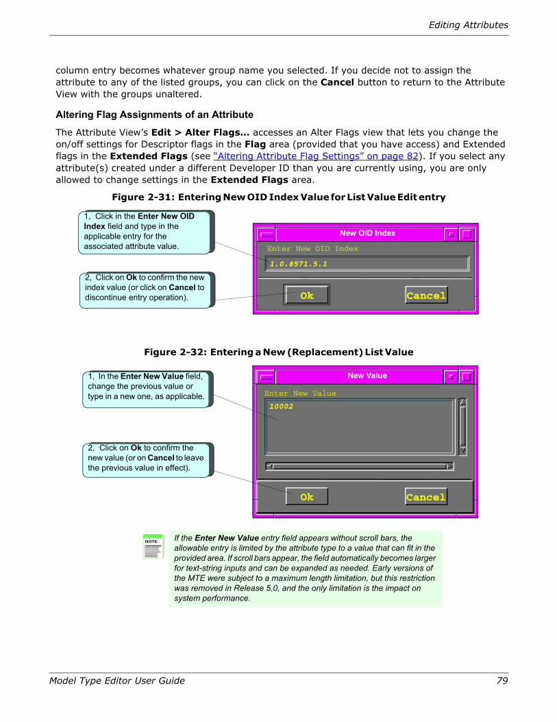
Editing Attributes
Model Type Editor User Guide 79
column entry becomes whatever group name you selected. If you decide not to assign the attribute to any of the listed groups, you can click on the Cancel button to return to the Attribute View with the groups unaltered.
Altering Flag Assignments of an Attribute
The Attribute View’s Edit > Alter Flags… accesses an Alter Flags view that lets you change the on/off settings for Descriptor flags in the Flag area (provided that you have access) and Extended flags in the Extended Flags (see “Altering Attribute Flag Settings” on page 82). If you select any attribute(s) created under a different Developer ID than you are currently using, you are only allowed to change settings in the Extended Flags area.
Figure 2-31: Entering New OID Index Value for List Value Edit entry
Figure 2-32: Entering a New (Replacement) List Value
Enter New OID Index
New OID Index
Ok Cancel
1.0.8571.5.1
1, Click in the Enter New OID Index field and type in the applicable entry for the associated attribute value.
2, Click on Ok to confirm the new index value (or click on Cancel to discontinue entry operation).
Enter New Value
New Value
Ok Cancel
10002
NOTE If the Enter New Value entry field appears without scroll bars, the allowable entry is limited by the attribute type to a value that can fit in the provided area. If scroll bars appear, the field automatically becomes larger for text-string inputs and can be expanded as needed. Early versions of the MTE were subject to a maximum length limitation, but this restriction was removed in Release 5.0, and the only limitation is the impact on system performance.
1, In the Enter New Value field, change the previous value or type in a new one, as applicable.
2, Click on Ok to confirm the new value (or on Cancel to leave the previous value in effect).

80 Model Type Editor User Guide
Chapter 2: Using the MTE
Figure 2-33: Error Message If You Try to Delete List Value Without First Selecting Associated OID Index Entry
Error
Must select an OID Index to delete
Close

Editing Attributes
Model Type Editor User Guide 81
Figure 2-34: Altering an Attribute Group
Attribute View
File Edit View
Derivable
Required
Instantiable
Unique
Visible
No Destroy
For Model Type:Entity Types
Attribute Names
<empty> 1154e EntityTypes
Values Attr ID Attr Group
<no group>EntityTypesRootRootRootRootRoot<no group>Root
11aef1154b11b4711b411007c110b411b3d11ae3111f1
0NONE.00002104.00.00
ntityTypes CS condition_assertionntityTypes CS EntityTypesCS EntityTypes CS Normal_View_TypeCS Root CS createdateCS Root CS createtimeCS Root CS Model_StateCS Root CS model_verifyCS Root CS PollingMultiplierCS Root CS RootCS Root CS Version_Number
Copy Ctrl+InsPaste Shift+Ins
Rem Attributes…Alter Value…Alter Group…Alter Flags…
ntityTypes CS Normal_View_Type
*
Group/Attributes
Attribute Group List
CancelOK
Explode All
Collapse AllCollapse
Explode
Clear Group
RevisionHistoryMgmntProtocolVersionNumberDescription
TCPConnTableTCP_Conn_Remote_PortTCP_Conn_Remote_AddrTCP_Conn_Local_PortTCP_Conn_Local_AddrTCP_Conn_State
IcmpICMP_Out_Echos_RepeatsICMP_In_Addr_Masks_RepeatsICMP_In_Time_ExceededICMP_Out_TimestampsICMP_Out_MessagesICMP_In_Parm_Prob
Icmp
TCPCommTable
2. Select the Edit > Alter Group… option to open the Attribute Group List dialog box.
1. In the Attribute View, select the attribute(s) in the Attribute Names list that you want to add to a group.
Shortcut for 1 & 2: Double-click on the Attr Group column entry to open Attribute Group List dialog box for that attribute.
3. In the resulting Attribute Group List window, click on the line for the group to which you wish to add the previously selected attribute(s).
Group name entries are shaded, set flush left. When you select a group name entry, that entry becomes back-lighted to confirm
If you decide not to add the attribute(s), click on Cancel button to quit the setup.
4. Click on the OK button to confirm your assignment(s).
Shortcut for 3 & 4: Double-click on desired attribute group entry to assign previously selected attribute(s).
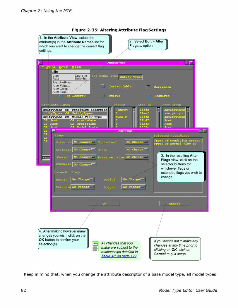
82 Model Type Editor User Guide
Chapter 2: Using the MTE
Figure 2-35: Altering Attribute Flag Settings
Keep in mind that, when you change the attribute descriptor of a base model type, all model types
Attribute View
File Edit
Derivable
Required
Instantiable
Unique
Visible
No Destroy
For Model Type:Entity Types
Attribute Names
<empty> 1154e EntityTypes
Values Attr ID Attr Group
<no group>EntityTypesRootRootRootRootRoot<no group>Root
11aef1154b11b4711b411007c110b411b3d11ae3111f1
0NONE.00002104.00.00
ntityTypes CS EntityTypes
CS Root CS createdateCS Root CS createtimeCS Root CS Model_StateCS Root CS model_verifyCS Root CS PollingMultiplierCS Root CS RootCS Root CS Version_Number
Copy Ctrol+InsPaste Shift+InsRem Attributes…Alter Value…Alter Group…Alter Flags…
ntityTypes CS Normal_View_Type
ntityTypes CS condition_assertionntityTypes CS condition_assertion
ntityTypes CS Normal_View_Type
View
2. Select Edit > Alter Flags… option.
Alter Flags
Flags
External
Readable
Writable
Shared
Extended Flags
Memory
Database
Polled
Logged
No Change CS Root CS PollingMultiplierGuaranteed
Global
Preserve Value
OK Cancel
Selected Attributes
No Change
No Change
No Change
No Change
No Change
No Change
No Change
No Change
No Change
No Change
3. In the resulting Alter Flags view, click on the selector buttons for whichever flags or extended flags you wish to change.
4. After making however many changes you wish, click on the OK button to confirm your selection(s). NOTE All changes that you
make are subject to the relationships detailed in Table 3-1 on page 129.
Types CS condition assert iTypes CS Normal_View_Ty
If you decide not to make any changes at any time prior to clicking on OK, click on Cancel to quit setup.
*
1. In the Attribute View, select the attribute(s) in the Attribute Names list for which you want to change the current flag settings.

Creating and Managing an Attribute Group
Model Type Editor User Guide 83
derived from that model type throughout the hierarchy are also automatically modified to match the new attribute descriptor in the base model type.
When you change the attribute extension of a base model type, however, all model types derived from the base model type may not necessarily change accordingly. The change depends on whether the derived model type has inherited the identical attribute extension from the base model type. The number of different derived model types is limited only by the number of different attribute extensions the user creates. For more information on the effects of model type inheritance and editing attributes, refer to “Model Type Inheritance” on page 17.
You must be aware of both current and desired flag settings before coming to the Alter Flags dialog box, as there is no indication in that view as to what the current setting is; all selection buttons carry a No Change readout. To make a change, click the left mouse button on a given button, activating a No Change/True/False selection menu for that flag. Click on whichever of these three settings you want, repeating as applicable for each desired flag change. Keep in mind that all settings must comply with the relationships shown in Table 3-1 on page 129. When all desired changes have been completed, click on the OK button to confirm those settings and return to the Attribute View with the new settings in effect—or else click on the Cancel button to exit from the dialog box without making any changes.
Creating and Managing an Attribute Group
Up until Release 5.0, users could create an attribute group, using the same process described in “Adding Attributes to a Model Type” on page 56 by selecting it as a Group ID type and then adding attributes to that group. The Group ID type choice is no longer available when creating a new attribute. MTE has been revised to let you create attribute groups directly, and you can then add new attributes to those groups or remove old ones from groups, at will. The mechanism for this new capability is a revamped Attribute Group List dialog box, which now comes in two formats:
• A full configuration when called to create or modify groups themselves (see Figure 2-36 on page 84 and Figure 2-37 on page 85).
• A less complex configuration when all you want to do is assign or alter the assignment of one or more attributes to a group (see Figure 2-38 on page 86).
When you pull down the View menu on the Attribute View’s menu bar and click on its Groups… option, the MTE opens the fully configured Attribute Group List dialog box, as illustrated in Figure 2-36 on page 84, showing closed view of hierarchy, and Figure 2-37 on page 85, showing fully exploded view of hierarchy.

84 Model Type Editor User Guide
Chapter 2: Using the MTE
Figure 2-36: Attribute Group List for a Representative Model (Groups Collapsed)
Several buttons available in the Attribute Group List dialog box let you explore the attribute group hierarchy by exploding or collapsing different groups. You can also create groups, add to existing groups, clear them, or delete them. The names of attribute groups on the list are designated by use of a different background color than individual attributes. When a group is exploded, the attributes and/or subgroup names appear indented from the parent group on the list—and entries
Attribute View
File Edit
Derivable
Required
Instantiable
Unique
Visible
No Destroy
For Model Type: Entity Types
Attribute Names
<empty> 1154e EntityTypes
Values Attr ID Attr Group
<no group>EntityTypesRootRootRootRootRoot<no group>Root
11aef1154b11b4711b411007c110b411b3d11ae3111f1
0NONE.00002104.00.00
CS EntityTypes CS condition_assert_infontityTypes CS EntityTypesCS EntityTypes CS Normal_View_TypeCS Root CS createdateCS Root CS createtimeCS Root CS Model_StateCS Root CS model_verifyCS Root CS PollingMultiplierCS Root CS RootCS Root CS Version_Number
Groups…
CS EntityTypes CS Normal_View_Type
CS EntityTypes CS condition_assert_infontityTypes CS condition_assertion
ntityTypes CS Normal_View_Type
View
If you decide not to make any changes, click on the Cancel button to quit the setup.
Explode
Collapse
Clear Group
Explode All
Collapse All
Cancel
Attribute Group ListGroup/Attribute
AdminifStatusAppExtrasMFAprismaAprismaFlagsCiscoCiscoAppsCiscoMibsCiscoNoveMibCiscoNovellAppCommonInfoCommonMMFragsDataRelayDelta_if_Up_TimeDellta_Octets_OmDelta_Octets_Out
AppExtrasMFAprismaFlagsCiscoCiscoAppsCiscoMibsCiscoNoveMibCiscoNovellAppCommonInfoCommonMMFragsDataRelay
AprismaFrags
Create Change/DescAdd to Delete
Ok
*
Attributes not assigned to any group appear in same primary-level sequence (flush left), in alphabetical order, with no background.
To examine the attributes in all groups at once, click on Explode All button (see following figure for results).
Attribute group names are identified by colored background bands across screen. (Color determined by mte*groupcolor resource.)
1. In the Attribute View, select the View > Groups… option to open Attribute Group List dialog box.
To examine the attributes in a group, select that group with cursor (note color change of band) and then click on Explode button.

Creating and Managing an Attribute Group
Model Type Editor User Guide 85
in subgroups are indented even further, to provide quick visual identification of the hierarchical structure, as shown in Figure 2-37.
Figure 2-37: Attribute Group List for a Representative Model (Groups Exploded)
The attribute groups available for a model type are presented as a hierarchical structure, with unassigned individual attributes at the same level as primary attribute groups (see Figure 2-36 on page 84). An attribute group can consist of individual attributes and attribute groups assembled under an assigned Attribute Group ID, as is illustrated by the Attribute Group List display, which shows assigned elements at a next-level indentation (see Figure 2-37 on page 85). Similarly, the attributes and/or subgroups assigned to a given subgroup are shown as the next-lower indentation level, with this same indentation representation being repeated for each successive level of subordination.
Figure 2-38 on page 86 shows the other version of the Attribute Group List dialog box, which appears when you perform any of the following actions, all of which involve assigning or reassigning one or more attributes to a particular attribute group:
Change/Desc
Attribute Group ListGroup/Attribute
AprismaFragsAutoDiscoverygib_model_name_menuNotesgib_mtype_namegib_mtype_name_menugib_model_name
Last_Successful_Poll
zoomedListAutoPlaceRowOffsetXVIB_X_Position
AprismaFragsGlobalMFrag
The exploded view of a group shows the result of having exploded the AprismaFrag group twice, thereby displaying two levels of subgroups and contained attributes, each arranged in alphabetical sequence within the assigned group order, with successive subgroup levels being indicated by successive indentation.
LastSuccPollMF
VIBTo clear a group, removing assignment from all attributes in that group, click on (highlight) the group name and then click on Clear Group button, setting that group’s value to 0 (zero).
AppExtrasMF
Add toCreate Delete
Clear Group
Collapse
Explode
Collapse All
Explode All
Ok Cancel
If you decide not to make any changes, click on the Cancel button to quit the setup without making changes.
To delete a group that you own, click on (highlight) group name and then click on Delete button. (The selected group must be empty, with all of its attributes previously removed.)
To create a new group, click on Create button to open New Attr Group dialog box (see Figure 2-43 on page 90).

86 Model Type Editor User Guide
Chapter 2: Using the MTE
Figure 2-38: Assigning an Attribute to an Attribute Group
The controls in the Attribute Group List and their functions are as follows:
The Ok button confirms the assignment of previously selected attribute(s), as selected in whichever view you accessed the Attribute Group List dialog box from, to whichever group name subsequently was selected in this Attribute Group List dialog box. (Hint: the same result can be achieved even more easily simply by double-clicking on the group name after accessing this dialog box.)
If you select an attribute in the Attribute Group list rather than an attribute group, and attempt to complete the assignment, the MTE presents an error message box, as shown in Figure 2-39 on page 87. You must then close that box and start over.
Ok
Group Attributes
Attribute Group List
CancelOk
Explode All
Collapse AllCollapse
Explode
Clear Group
GlobalMFragNotesgib_mtype_namegib_mtype_name_menugib_model_namegib_model_name_menu
AutoDiscoveryADiscClassFrag
ConnectionPrecDataRelayClassGeneralDiscClass
ADiscDRelayRepADiscDataRelayMH
CommonInfoDescriptionSystem_Up_TimeContactPerson
If you decide not to select an attribute, click on the Cancel button to quit the setup without making changes.
To assign currently selected attribute(s) to a group, select the desired group name and then click on the OK button —or simply double-click on the group name.
GlobalMFrag
AutoDiscoveryADiscClassFrag
ADiscDRelayRep
CommonInfo
System_Up_Time
Attribute group names are identified by colored bands across screen.
Attributes and subgroups within a group are indented under the group name.

Creating and Managing an Attribute Group
Model Type Editor User Guide 87
Figure 2-39: Error Message If You Try to Assign Attribute(s) to Another Attribute
The Cancel button closes the Group Attribute List dialog box without performing any changes on database.
The Explode button expands a selected (previously highlighted) attribute group name to show all of its next-lower-level attribute groups and individual attributes.
For example, Figure 2-40 on page 87 diagrams the result of exploding the primary AprismaFrag group shown in Figure 2-36 on page 84, revealing the seven next-level attribute groups which make up that group:
Figure 2-40: Effect of “Exploding” Representative Attribute Group
Similarly, Figure 2-41 on page 88 diagrams the result of exploding the second-level GlobalMFrag group in the preceding diagram, revealing the five third-level attributes which make up that group:
Cancel
Explode
Error
Attribute selected is not a group.
Close
AdminiStatusAppExtrasMFAprismaFrags
GlobalMFragLastSuccPollMFVIBSpectroWatchAutoDiscoveryModelElementLostFoundMFrag
CommoninfoCommonMMFragsDataRelay
CollapseExplode
AdminiStatusAppExtrasMFAprismaFragsCiscoCiscoAppsCiscoMibsCiscoNoveMibCiscoNovellAppCommonInfoCommonMMFragsDataRelayDelta_sif_Up_TimeDelta_Octets_OmDelta_Octets_Out
AppExtrasMFAprismaFrags
GlobalMFragLastSuccPollMFVIBSpectroWatchAutoDiscoveryModelElementLostFoundMFrag
CommoninfoCommonMMFragsDataRelayDelta_sif_Up_TimeDelta_Octets_OmDelta_Octets_Out
CollapseExplode

88 Model Type Editor User Guide
Chapter 2: Using the MTE
Figure 2-41: Effect of Further Exploding Into Higher- Order Subgroups
The Explode All button shows all the attribute groups and individual attributes throughout the hierarchy, expanding all attribute groups to their lowest levels. The results thus are the same as would be obtained by repeating the preceding operation for every group and subgroup in the hierarchy for the given model type (see Figure 2-37 on page 85).
The Collapse button hides the attribute groups and individual attributes at all levels beneath the currently selected (previously highlighted) attribute group.
In the case of the previous diagram, therefore, highlighting the GlobalMFrag group name and clicking on Collapse would return the display to the second-level breakdown shown in the left side of that diagram. Similarly, highlighting and clicking on the AprismaFrags group name would close up all subgroups under that primary group, as shown in Figure 2-42 on page 89.
Explode All
Collapse
AdminiStatusAppExtrasMFAprismaFrags
GlobalMFragLastSuccPollMFVIBSpectroWatchAutoDiscoveryModelElementLostFoundMFrag
CommoninfoCommonMMFragsDataRelayDelta_sif_Up_TimeDelta_Octets_OmDelta_Octets_Out
AdminiStatusAppExtrasMFAprismaFrags
GlobalMFraggib_model_name_menuNotesgib_mtype_namegib_mtyype_name_menugib_model_name
LastSuccPollMFVIBSpectroWatchAutoDiscoveryModelElementLostFoundMFrag
CommoninfoCommonMMFrags
CollapseExplode

Creating and Managing an Attribute Group
Model Type Editor User Guide 89
Figure 2-42: Effect of “Collapsing” Attribute Subgroups
The Collapse All button hides the contents (subgroups and individual attributes) of all attribute groups in the list (see Figure 2-36 on page 84).
The Clear Group button has two different functions, depending on how you access the Attribute Group List dialog box. If you open the restricted version of this dialog box by double-clicking on an attribute entry (or the last in a series of entries) in the Attribute View’s Attr Group, you can click on the Clear Group button to remove the attribute you double-clicked from its assigned group; the program then returns to the Attribute View, with the Attr Group entry for the attribute now reading <no group>. If you open the full version of this dialog box by selecting the Attribute View’s View > Groups option, however, you can select an attribute subgroup’s name and click on the Clear Group button to clear that assignment, setting that group’s Group ID to 0 (zero); the program then returns to the Attribute View with no visible change, but the next time you open the Attribute Group List dialog box you will find the selected subgroup (with its subgroups and attributes, if any, still intact), listed as an independent attribute group, ready for reassignment.
The Create button appears only when the Group Attribute List box is opened by selecting the Attribute View’s File > Groups… option. Clicking on this button causes the Group Attribute List dialog box to be replaced by a New Attr Group dialog box, as shown in Figure 2-43 on page 90. The new Group name may consist of letters, numbers, underscore (_) characters, and dashes (-). Spaces, punctuation, or other symbols are not allowed. The Group name cannot be more than 128 characters in length.
Collapse All
Clear Group
Create
AdminiStatusAppExtrasMFAprismaFrags
GlobalMFraggib_model_name_menuNotesgib_mtype_namegib_mtyype_name_menugib_model_name
LastSuccPollMFVIBSpectroWatchAutoDiscoveryModelElementLostFoundMFrag
CommoninfoCommonMMFrags
AdminiStatusAppExtrasMFAprismaFragsCiscoCiscoAppsCiscoMibsCiscoNoveMibCiscoNovellAppCommonInfoCommonMMFragsDataRelayDelta_sif_Up_TimeDelta_Octets_OmDelta_Octets_Out
CollapseCollapse
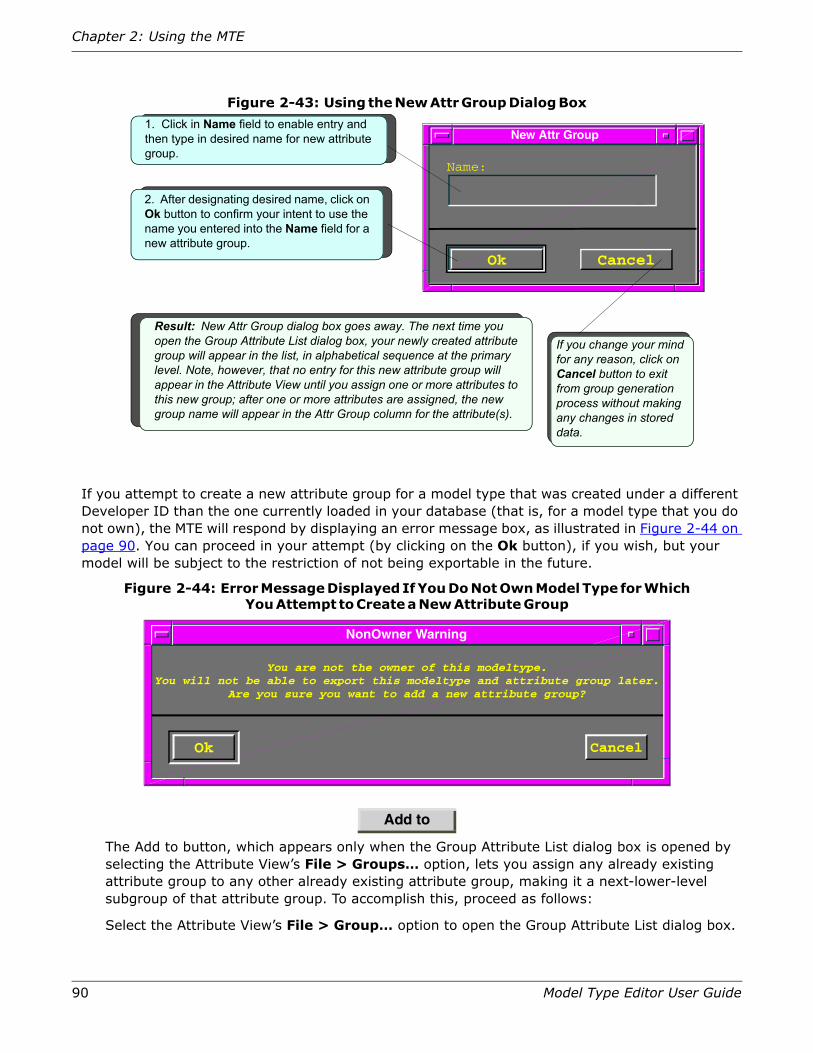
90 Model Type Editor User Guide
Chapter 2: Using the MTE
Figure 2-43: Using the New Attr Group Dialog Box
If you attempt to create a new attribute group for a model type that was created under a different Developer ID than the one currently loaded in your database (that is, for a model type that you do not own), the MTE will respond by displaying an error message box, as illustrated in Figure 2-44 on page 90. You can proceed in your attempt (by clicking on the Ok button), if you wish, but your model will be subject to the restriction of not being exportable in the future.
Figure 2-44: Error Message Displayed If You Do Not Own Model Type for Which You Attempt to Create a New Attribute Group
The Add to button, which appears only when the Group Attribute List dialog box is opened by selecting the Attribute View’s File > Groups… option, lets you assign any already existing attribute group to any other already existing attribute group, making it a next-lower-level subgroup of that attribute group. To accomplish this, proceed as follows:
Select the Attribute View’s File > Group… option to open the Group Attribute List dialog box.
Add to
1. Click in Name field to enable entry and then type in desired name for new attribute group.
If you change your mind for any reason, click on Cancel button to exit from group generation process without making any changes in stored data.
2. After designating desired name, click on Ok button to confirm your intent to use the name you entered into the Name field for a new attribute group.
Result: New Attr Group dialog box goes away. The next time you open the Group Attribute List dialog box, your newly created attribute group will appear in the list, in alphabetical sequence at the primary level. Note, however, that no entry for this new attribute group will appear in the Attribute View until you assign one or more attributes to this new group; after one or more attributes are assigned, the new group name will appear in the Attr Group column for the attribute(s).
New Attr Group
Ok Cancel
Name:
Do you wish to apply your
NonOwner Warning
You are not the owner of this modeltype.You will not be able to export this modeltype and attribute group later.
Are you sure you want to add a new attribute group?
Ok Cancel

Creating and Managing an Attribute Group
Model Type Editor User Guide 91
In that dialog box’s Group/Attribute scroll field, locate and select (highlight) the attribute group which you want to assign to another attribute group.
Click on the Add to button.
In the Group/Attribute scroll field, locate and double-click the line entry for the attribute group to which you want to assign the just-selected attribute group.
The Group Attribute List dialog box goes away when you perform this last step. When you next open that dialog box, you will find that the attribute group (and any attributes and attribute groups assigned to that attribute group) will now be assigned as a next-lower-level function of the attribute group which you double-clicked.
The Delete button, which appears only when the Group Attribute List dialog box is opened by selecting the Attribute View’s File > Groups… option, lets you delete an attribute group (but not an attribute). To accomplish this, proceed as follows:
In the Group Attribute List dialog box’s Group/Attribute scroll field, locate and select (highlight) the attribute group which you want to delete. (Viewing the field, confirm that no attributes currently are assigned to that attribute group; you will not be able to delete a attribute group that is not empty.)
Click on the Delete button.
The Group Attribute List dialog box goes away when you perform this last step. When you next open that dialog box, you will find that the selected attribute group no longer is listed in the Group/Attribute scroll field.
If you select an attribute, instead of an attribute group, and then click on the Delete button, the MTE will present an error message dialog box, as illustrated in Figure 2-45 on page 91.
Figure 2-45: Error Message If You Select Attribute and Click Delete Button
When you close this error message box, the Group Attribute List dialog box remains active, with your selection still highlighted. You must change the selection to an empty group or else click on the Cancel button.
If you click on the Delete button after selecting an attribute group to which attributes are still assigned, no deletion will occur. Instead, the MTE will display an Error message box, reading:
User may not remove an attribute group that isn’t empty.Remove any objects from this group first.
Delete
Error
Group selection required
Close

92 Model Type Editor User Guide
Chapter 2: Using the MTE
When this error message appears, the MTE leaves the Group Attribute List dialog box displayed, with the selected attribute group still highlighted. You can clear that group at this time by clicking on the Clear Group button, if you wish, but you will not be able to delete it from the hierarchy until you either remove or reassign all the attributes or attribute groups assigned to it. (To remove an attribute, refer to “Removing Attributes” on page 58. To reassign an attribute to a different attribute group, refer to the discussion of the Ok button preceding Figure 2-39 on page 87. To reassign a subgroup to a different attribute group, refer to the discussion of the Add to button following Figure 2-44 on page 90.)
The Change/Desc button, which appears only when the Group Attribute List dialog box is opened by selecting the Attribute View’s File > Groups… option, lets you change the name of an existing attribute group. To do this, proceed as follows:
1. Select the Attribute View’s File > Group… option to open the Group Attribute List dialog box.
2. In that dialog box’s Group/Attribute scroll field, locate and select (highlight) the attribute group whose name you want to change.
3. Click on the Change/Desc button.
The Group Attribute List dialog box goes away, being replaced by the Change Group Name dialog box (see Figure 2-46 on page 93).
4. In that new dialog box, click in the Group Name field and then modify the existing contents as desired, subject to the following restrictions:
• Other than the underscore character (_), you cannot use any keyboard character other than regular alphanumerics. If you try to do so, the MTE will display an error message reading:
Only numbers, letters, and underscores allowed in name.
• You must be the owner of the current model type (that is, the model type containing the attribute group whose name you are trying to change must have been created under the same Developer ID you are currently using— even if the subject attribute group is one that you created in that model type after being warned that you would not be able to export the model type or the attribute group. If you try to modify the name of a attribute group in a model type that you do not own, the MTE will display an error message reading:
The user is not the owner of the current Model Type.You are not allowed to rename the current Attribute Group.
• You cannot change the name of an existing attribute group to be the same as any already existing attribute group created under the same Developer ID— even if the existing attribute is a subgroup under some other attribute group. If you attempt to do this, the MTE will display an error message reading:
• Duplicate group name not allowed.
• You cannot change the name of an inherited attribute group that originates in some ancestor model type. If you attempt to do this, the MTE will display an error message reading:
Not allowed to rename an inherited attribute group.
Change/Desc

Creating and Removing Relations
Model Type Editor User Guide 93
Figure 2-46: Using the Change Group Name Dialog Box
Creating and Removing RelationsAs explained earlier (“Relations” on page 15), associations between SPECTRUM models are defined according to the concepts of relations and rules. A relation, such as Contains, describes the way in which two associated models can interact, while a rule is a statement that applies the relation to two specific models, such as “Model A Contains Model B.” For each relation in SPECTRUM there is a master set of meta-rules that specifies which model types can be associated through that relation. New relations can be added to represent a new way of relating either new or existing model types. New meta-rules can then be added to implement the new relation. If you add a new relation, you must also add new intelligence to the model types so that the resulting models will react when they are associated with other models under the new relation. This intelligence must be implemented programatically with the CORBA API. See the CORBA API Programmer Guide for more information.
1. Click in Group Name text field to enable entry and then modify or replace existing attribute group name.
If you change your mind for any reason, click on Cancel button to exit from group name changing process without making any changes in stored data.
Result: Change Group Name dialog box goes away, and new version of just-changed name of attribute group now appears wherever applicable in Attr Group column of Attribute View. The next time you open the Group Attribute List dialog box, your newly created attribute group name will appear on the list, where applicable.
Change Group Name
Ok Cancel
Group Name:
Group Handle:
Originating Model Type:
Phase_Setup
180006
SPTR ACME2_PS2 SPTR
Group Handle is shown for your convenience; you cannot change this value.
Originating model type is identified for convenience; you cannot change any part of this value.
2. After changing Group Name entry as desired, click on Ok button to confirm your intent to use name now appearing in the Group Name field for current attribute group.

94 Model Type Editor User Guide
Chapter 2: Using the MTE
Creating a New Relation
To create a new relation:
1. From the Model Type View, select the View > Relations option to access the Relation View (see Figure 2-47).
Figure 2-47: Relation View
2. Select the File > New Relation… option to open a special version of the Meta–Rule View (see Figure 2-48 on page 95), which functions in place of the New Relation dialog box used in prior versions of MTE.
3. Follow the steps shown in the sequence from Figure 2-48 on page 95 through Figure 2-52 on page 98 to enter the desired relation name and select the desired members for one or more meta-rules defining the new relation.
You can use alphanumeric characters or underscores in the name, with a maximum length of 31 characters, but do not use spaces or punctuation. (An error box will appear to notify you of any such illegal characters, and the program will not let you continue with an unacceptable name.)
Relation View
File Edit
CS Application
CS Can_Assign
CS Collects
CS Connects_to
CS Contains
CS Encompasses
CS Executes
CS File_Server
CS Has_Member
CS HASPART
CS Indirect_Model_Of
CS Is_Adjacent_to
CS Is_Assigned
CS Is_Bounded_By
CS IsServerTo
CS Links_with
CS Lost_and_Found
CS Mail_Server
Relation NamesHandles
1013
1001b
10002
10005
10001
10003
10006
10011
10022
10004
1001e
10007
1001c
10024
10025
10023
10010
10014
New Relation…Open Relation…
Close Relation View
Select File > New Relation… option.
*
Filter Relations by mtype…Clear mtype Filter…

Creating and Removing Relations
Model Type Editor User Guide 95
Figure 2-48: Set-up of Initially Empty Rule View Called by New Relation… Option
Figure 2-49: Defining a Relation Type for a New Relation
Model Types:
Base Model Types:
Model Type Handle:
Model Type Name:UPS_4192
79c312
Model Type View
Derived Model Types:
ACME EntityTypesACME ManufacturerACME ModelFragmentACME MMDeveloperACME commonACME AppDataRoot
File Edit View
Meta–Rule View
File Edit
Relation Name:
Relation Type: One-to-many
Meta–Rules
2. Click in Relation Name text block and type in applicable name for desired meta-rule.
3. If new meta-rule is to be a many-to-many type, click on button and select alternate value (see Figure 2-49 on page 95)..
4. Pull down File menu and click on New Meta–Rule… option (see Figure 2-50 on page 96).
1. From Model Type View for model type for which you want to create new relation, select View > Relations to open Relation View, then select File > New Relation.
*
*
Many-to-many
One-to-many
To change default relation type to the alternate value, click on the relation-selector button in the Type field. (After you save your work to the database, at which time the program assigns a handle, you will not be able to change this selection.)
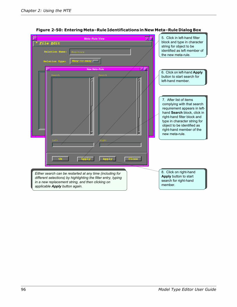
96 Model Type Editor User Guide
Chapter 2: Using the MTE
Figure 2-50: Entering Meta–Rule Identifications in New Meta–Rule Dialog Box
Meta–Rule View
File Edit
Relation Name:
Relation Type: Many-to-many
Rules
Monitors
New Meta–Rule
Ok Apply
Left
Search Search
Right
Apply Close
5. Click in left-hand filter block and type in character string for object to be identified as left member of the new meta-rule.
Either search can be restarted at any time (including for different selections) by highlighting the filter entry, typing in a new replacement string, and then clicking on applicable Apply button again.
6. Click on left-hand Apply button to start search for left-hand member.
8. Click on right-hand Apply button to start search for right-hand member.
7. After list of items complying with that search requirement appears in left-hand Search block, click in right-hand filter block and type in character string for object to be identified as right-hand member of the new meta-rule.
*

Creating and Removing Relations
Model Type Editor User Guide 97
Figure 2-51: Selecting Rule Elements and Confirming Selections in New Meta–Rule Dialog Box
You must use a unique name for the relation—meaning that you cannot use a name that is currently being used in any model type that was created with the Developer ID currently assigned to your database. If you attempt to create a relation using the same name as an existing relation, an error dialog box will appear, presenting a “Name entered is not unique for the current developer” message, and the new relation will not be created. Two different developers (that is, users whose databases have different Developer IDs assigned to them) can create relations using the same name, but there will be no conflict in such a case, because of the different developer IDs.
Meta–Rule View
File Edit
Relation Name:
Relation Type: Many-to-many
Rules
Monitors
New Meta–Rule
Ok Apply
Left
Search Search
Right
Apply Close
CSE13 RtrCayGMIMCSE15 Hub3ComFMSIICSEU Hub_UB_790s4CSEU HubCSIFDDICSFH HubCSIMBXiCSE5 HubCSITBMMCSRT StdRtrDerPtCSRT VinesRtrDerPtCSRT XNSRtrDerPtCSSH Rtr_Shiva_FP5CSTR HubCSITBMMCYMN IMIMRtrCsyGMIMCYMN INIMRtrCyGStarCYMN RtrCayGBoxIM HubCSIEMMESEHI HubCSISEHIuMAC BRtrCSIuMMACWLFT LwfGenRtrApp
CM LbBlankMimCS GoUp_LandscapeCS IMIMNovLANMIMCS IndrctLANternCS LANCS LAN_802_3CS LANJ_802_5CS LAN_TypesCS LANPortCS NA_Nov_LANMIMCS NA_Nov_LANternCS RingLANTypesCS RxLANPsortSCSE12 HubLanPlx5004CSE12 HubLanPlx5012CSE12 HubLanPlx6004CSE12 HubLanPlx6012CSE12 LanPlexApps
CS LAN_802_3SPTR Hub3ComFMS11
CS LAN_802_3
Hub3ComFMSIISPTR
9. In left-side Search block, click on entry to select item you want identified as left-hand member of the new meta-rule.
10. In right-side Search block, click on entry to select item you want identified as right-hand member of the new meta-rule.
11. When desired entry has been selected for both sides of meta-rule, click on Ok button to confirm selection.
If so desired, for any reason, you can click on Close button at any time to exit from relation creation procedure without any change to existing relations.
*

98 Model Type Editor User Guide
Chapter 2: Using the MTE
Figure 2-52: Making Final Confirmation of New Meta–Rule in Rule View
If you remove a relation for any reason and then subsequently wish to recreate a relation with the same name as the one you removed, you can do so, but it will have a different handle assigned by the automatically incremented counter.
After confirming the name of the new relation, the MTE automatically assigns a handle. The new relation name then appears in the list of relations presented in the Relation View screen (Figure 2-53 on page 99).
Removing a Relation
You cannot remove a relation created under a different Developer ID than the one loaded in your database. To remove a relation and the meta-rules it contains, provided that you do have access, proceed as follows:
1. In the Model Type View, pull down the View menu and activate the Relations… option to open the Relation View.
2. From the Relation Names scroll list, select (highlight) the name of the relation you want to remove.
Meta–Rule View
File Edit
Relation Name:
Relation Type: Many-to-many
Meta–Rules
Monitors
SPTR Hub33ComFMSII CS LAN_802_3
12. Confirm that resulting meta-rule expression is what you wanted.
13. Repeat all of the preceding steps for as many meta-rules as you wish to define for the new relation at this time.
*
14. Select File > Save and Close option and then click on Save and Close button in resulting Save Changes dialog box.

Creating and Removing Relations
Model Type Editor User Guide 99
Figure 2-53: Relation View, Showing New Relation Added to Scroll List
3. Double-click on that highlighted entry (or activate the File > Open Relation… option) to display the Meta–Rule View, listing all of the meta-rules pertaining to the selected relation.
4. Select each meta-rule in the Meta–Rules scroll list in turn, highlighting all entries.
5. Select the Edit > Rem Meta–Rules… option.
6. Confirm that the resulting Cut List dialog box (see Figure 2-9 on page 46) accurately lists the selected meta-rules in its Selected Items list.
7. Click on the OK button to confirm that the listed meta-rules are to be removed. (If you decide for any reason that one or more of the listed items should not be removed, you can click on the Cancel button to exit from the process without making any changes in the database.)
Presuming that the meta-rules in question were created under the Developer ID you are using and that no other conditions exist that would generate an error message, the system then removes all of the selected meta-rules, returning you to the Meta–Rule View, which now shows an empty Meta–Rules scroll list area.
8. Select the File > Save and Close option then click on the Save and Close option of the resulting Save Changes dialog box to return to the Relation View.
9. If you wish to remove other relations at this time, repeat the preceding procedure, from step 2 through step 8, to remove all meta-rules from each relation that you wish to remove (or, if you prefer, proceed as follows to remove the already cleared relation and then do the others in turn).
Relation View
File Edit
Relation Names Handles
10020
10021
230000
230001
230002
ca0000
1130001
d70002
d70001
3d0000
b70001
b70002
b70000
180001
CS
CS
CSCR
CSCR
CSCR
CSE5
KTRX
SANM
SANM
SNMP
SOS
SOS
SOS
SPTR
Provides
Seems_Adjacent_to
PossPrimApp
USES
USING
project_contains
Pings_Through
Has_Filters
Is_Associated_With
Has_Relay_Function
EMSManages
InEMSMap
Presents
Monitors
*

100 Model Type Editor User Guide
Chapter 2: Using the MTE
10.Confirm that the relation you wish to remove is highlighted (clicking on it if necessary—and holding down the Control key if you wish to select more than one relation for removal).
11.Select the Edit > Rem Relations… option to request the system to remove the selected relation.
12. In the resulting Cut List dialog box (see Figure 2-9 on page 46), confirm that the relation(s) you intend to remove is/are correctly listed in the Selected Items text block.
13.Click on the Ok button to request the system to remove the listed relation(s). (If you decide for any reason that one or more of the listed items should not be removed, you can click on the Cancel button to exit from the process with no changes being performed.)
Note: You cannot remove relations that were not created with the Developer ID currently assigned to your database, and you cannot remove any relations from which the defining meta-rules have not already been removed; any attempt to do so will produce an error message informing you of the applicable situation, with no deletions being made.
Creating and Removing Meta–RulesEach relation normally has one or more meta-rules, each of which applies the relation to specific model types. Many of the model types in the core database have relations that are supplied without meta-rules; these function as “place holders” for which you can supply customized meta-rules pertaining to your specific systems. From the Relation View, which lists all of the relations that have been defined for the current model of interest, you can access the Meta–Rule View, in order to identify what meta-rules have been defined for a given relation. To do this, you either double-click on a given relation in the Relation Names scroll list on the Relation View, or else click on the relation entry to highlight it and then select File > Open Relation.
Figure 2-54 on page 101, for example, shows the Meta–Rule View for the Contains relation for the current model type (as concurrently listed in the Model Type Name field in the Model Type View). The Meta–Rule View identifies the currently defined meta-rules as a list of paired items, identifying the model types to which the given relation applies. Each line in the Meta–Rules text block is a separate meta-rule, having a left-hand element and a right-hand element. To understand a meta-rule, you read the two sides with the relation name between the left side and right side. In the Meta–Rules list shown in Figure 2-54, for example, you would read the first meta-rule as MMACPlus Contains MMPModule Frag, the second meta-rule as Building Contains Floor, and so on.

Creating and Removing Meta–Rules
Model Type Editor User Guide 101
Figure 2-54: Meta–Rule View, Showing Currently Defined Meta–Rules for “Contains” Relation
Using General Model Types to Simplify Meta–Rule Writing
Using general model types (nearer to the top of the model type hierarchy) as base models for a model type permits widespread application of meta-rules. The more general the model type used, such as Device, the more model types are derived from it and thus inherit the meta-rule. For example, the Device model type has an Is_Adjacent_to relation, which include the meta-rule Device Is_Adjacent_to Device. Consequently, any model type derived from Device (that is, having Device as one of its base model types) can be adjacent to any other model type derived from Device. Using generalized meta-rules thus can simplify the writing of meta-rules and make more specific meta-rules unnecessary.
Creating a Meta–Rule
The process of creating a new meta-rule, which is an integral part of creating a new relation, is documented in the sequence shown in Figure 2-50 on page 96 through Figure 2-52 on page 98. Follow exactly that same procedure for adding a new meta-rule to an existing relation, as follows:
1. In the Model Type View, select the View > Relations option to open the Relation View.
2. In the Relations Name scroll list on the Relation View, select (highlight) the entry for the relation to which you wish to add a new meta-rule.
Meta–Rule View
File Edit
CM MMACPlus
CS Building
CS Building
CS Building
CS Country
CS Country
CS Country
CS Floor
CS Floor
CS Location
CS Panel
CS Panel
CS Panel
CS Rack
Relation Name:
CM MMPModuleFrag
CS Floor
CS Room
CS Section
CS Building
CS Region
CS Site
CS Room
CS Section
CS Landscape
CM MMACPlus
CS Device
CS Physical_Addr
CM MMACPlusCS Rack CS Device
Relation Type:
Contains
One-to-many
Meta–Rules
*
Rack Contains Device

102 Model Type Editor User Guide
Chapter 2: Using the MTE
3. Select the Relation View’s File > Open Relation… option to open the Meta–Rule View for the selected relation, which shows a list of already-defined meta-rules.
4. Select the Mate–Rule View’s File > New Meta–Rule… option to open a New Meta–Rule dialog box, as shown in Figure 2-50 on page 96.
5. To define the new meta-rule, perform the steps shown in Figure 2-50 on page 96. You can enter any desired character string in the case-insensitive Left and Right filter fields to target the desired elements for your meta-rule, and then click on the applicable left-hand and right-hand Apply buttons to search for each such element. The search will find all occurrences of the entered filter pattern, using both uppercase and lowercase characters. If your filter pattern were any one of lan, Lan, or LAN, for example, the search would list model types such as LAN, LAN_802_3, LAN_802_5, NA_Nov_LANtern, NA_Nov_LANMIM, etc.
6. Following successful completion of the two searches, select the applicable entry in each Search area to identify the left and right elements, respectively, and then click on the Ok button to confirm those selections.
7. Confirm that the new meta-rule correctly appears on the Meta–Rule View as a new entry.
8. Repeat steps 4 through 7 to add more meta-rules as needed.
9. When you have created all desired new meta-rules, Select the Meta–Rule View’s File > Save and Close option and then click on the Save and Close option of the resulting Save Changes dialog box).
Removing a Meta–Rule
Note: You cannot remove a meta-rule unless the Developer ID you are using “owns” one or more of the associated model types or relations.
If you remove a meta-rule that was supplied by another developer, your modification/removal may not survive through the next upgrade of SPECTRUM.
To remove a meta-rule from a relation, proceed as follows:
1. In the Model Type View, select the View > Relations option to open the Relation View.
2. In the Relation View’s Relations Name scroll list, either double-click on the entry for the relation from which you wish to remove one or more existing meta-rules, or else select (highlight) that relation entry and then select the File > Open Relation… option.
3. In the resulting Meta–Rule View, listing all of the meta-rules pertaining to the selected relation, select (highlight) whichever meta-rule(s) you wish to remove from the Meta–Rules scroll list (holding the Control key down if you wish to process more than one at a time), and then select the Edit > Rem Meta–Rules… option.
4. Confirm that the resulting Cut List dialog box accurately lists the selected meta-rule(s) in its Selected Items list and then click on the OK button to confirm that the listed meta-rule(s) is/are to be removed. (If you decide for any reason not to complete this process, you can click on the Cancel button to exit from the sequence with no changes being effected.)
If the meta-rules in question were created under the Developer ID you are using and no other conditions exist that would generate an error message, the system removes all of the selected meta-rules, returning you to the Meta–Rule View, with the selected meta-rules entries no

Creating and Removing Meta–Rules
Model Type Editor User Guide 103
longer appearing in the Meta–Rules scroll list. If an error condition exists, the system displays a modal error message box informing you of that fact, with no changes being made.
5. If you wish to remove other meta-rules at this time (from the same relation or different ones), repeat the preceding steps as applicable to remove all meta-rules that you wish to remove.
6. Close out of this operation by selecting the File > Save and Close option and then clicking on the Save and Close option of the resulting Save Changes dialog box) to return to the Relation View.

104 Model Type Editor User Guide
Chapter 2: Using the MTE

105
Chapter 3: The MTE Views
This chapter provides details concerning the various MTE views: the Model Type View, the Attribute View, the Attribute Edit View, the Relation View, and the Rule View. This coverage presumes that the reader is familiar with use of keyboard commands and mouse manipulations, as well as the various common dialog boxes, as discussed in the preceding section.
Using the MTE ViewsThe MTE provides five basic views that allow you to examine and edit model types, attributes, relations, and rules. The preceding section introduced these views, together with basic procedures for the associated dialog boxes and error messages. This section serves as a reference for the fields and menu options that appear in these MTE views, with each subsection describing a particular view. Refer to the general overview in “Using the MTE Dialog Boxes” on page 39 to learn how to use the menus and fields in these views and to navigate from one to another.
The MTE views are organized under two menu paths you can navigate through by using the mouse or the keyboard, as illustrated in Figure 3-1 on page 106:
• The Model Type View is the basic starting point for MTE operations. The first view to appear when you start the MTE, this view provides access to the model type hierarchy, letting you select through base model types higher in the hierarchy or derived model types lower in the hierarchy in order to access a specific model type.
• The Attribute View identifies the name, value, handle, and group of each attribute in the selected model type, together with the status of the model-type flags. Options available in this view let you add, edit, or remove attributes, as well as change the setting of the model-type flags.
• The Attribute Edit View lets you specify options for new attributes being added or modify previously established values for existing attributes.

106 Model Type Editor User Guide
Chapter 3: The MTE Views
Figure 3-1: The Model Type Editor Views
• The Relation View provides access to relations and associated rules pertaining to a selected model type. You navigate to this view when you want to add or remove relations or change the associated rules.
• The Rule View lets you add or remove rules pertaining to the relations identified in the Relation view.
Each path provides access to specific functions used to define model types within the SpectroSERVER database.
CS Gen_EPI_Dev
Model Types:
Base Model Types:
Model Type Handle:
Model Type Name: MMDeveloper
1037b
Model Type View
Derived Model Types:
CISC Cisco_DevsCM 9F106_02CM LB_ModuleCM MMACPlusCS ClientAppCS Gen_EPI_Agent
CS Root
Attribute ViewFile Edit
Derivable
Required
Instantiable
Unique
Visible
No Destroy
For Model Type: Entity Types
Attribute Names
<empty> 1154e EntityTypes
Values Attr ID Attr Group
<no group>EntityTypesRootRootRootRootRoot<no group>Root
11aef1154b11b4711b411007c110b411b3d11ae3111f1
0NONE.00002104.00.00
ntityTypes CS condition_assert_infontityTypes CS EntityTypesntityTypes CS Normal_View_TypeCS Root CS createdateCS Root CS createtimeCS Root CS Model_StateCS Root CS model_verifyCS Root CS PollingMultiplierCS Root CS RootCS Root CS Version_Number
View*
Text String
11ae6
RevisionHistoryName:
Type:
Polling Group:
OID Prefix:
OID Ref:
Attribute Extended Description
ExtendedFlags:
Flags:External
Readable
Writable
Shared
Guaranteed
Global
Memory
Database
Polled
Logged
0
Attribute Description
Group ID:
Single ValuePreserve Value
Attribute Edit ViewFile Edit* View
Relation ViewFile Edit View
CS ApplicationCS Can_AssignCS CollectsCS Connects_toCS ContainsCS EncompassesCS ExecutesCS File_ServerCS Has_MemberCS HASPARTCS Indirect_Model_OfCS Is_Adjacent_toCS Is_AssignedCS Is_Bounded_ByCS IsServerToCS Links_withCS Lost_and_FoundCS Mail_Server
Handles
10131001b10002100051000110003100061001110022100041001e100071001c1002410025100231001010014
*
Relation Names
Meta–Rule ViewFile Edit
CM MMACPlusCS BuildingCS BuildingCS BuildingCS CountryCS CountryCS CountryCS FloorCS FloorCS LocationCS PanelCS PanelCS PanelCS Rack
Relation Name:
CM MMPModuleFragCS FloorCS RoomCS SectionCS BuildingCS RegionCS SiteCS RoomCS SectionCS LandscapeCM MMACPlusCS DeviceCS Physical_AddrCM MMACPlus
CS Rack CS Device
Relation Type:
Contains
One-to-many
Meta–Rules
*
View
Relations…
File
Find ->New Model Type…Examine ->
File
New Relation…Open Relation…Close Relation View
Meta-Rule View
File
New Attribute…Open Attribute…
Set Filter Name/ID
Select File > Examine Attributes
or
Double-click on Model Type Name
menu option
entry
Model Type View
Select File > Open Attribute…(or on File > New Attribute…to get “dummy” setup)
or
Double-click on selected Attribute
Select File > Open Relation(or on File > New Relationto get empty setup)
or
Double-click on selected relation
Attribute Edit View
Attribute ViewRelation View
SelectView > Relationsmenu option
Set Filter…
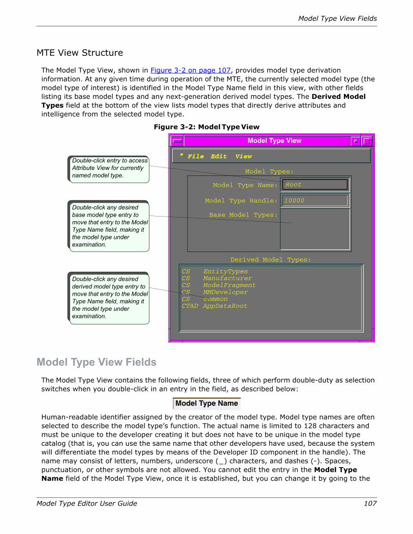
Model Type View Fields
Model Type Editor User Guide 107
MTE View Structure
The Model Type View, shown in Figure 3-2 on page 107, provides model type derivation information. At any given time during operation of the MTE, the currently selected model type (the model type of interest) is identified in the Model Type Name field in this view, with other fields listing its base model types and any next-generation derived model types. The Derived Model Types field at the bottom of the view lists model types that directly derive attributes and intelligence from the selected model type.
Figure 3-2: Model Type View
Model Type View FieldsThe Model Type View contains the following fields, three of which perform double-duty as selection switches when you double-click in an entry in the field, as described below:
Human-readable identifier assigned by the creator of the model type. Model type names are often selected to describe the model type’s function. The actual name is limited to 128 characters and must be unique to the developer creating it but does not have to be unique in the model type catalog (that is, you can use the same name that other developers have used, because the system will differentiate the model types by means of the Developer ID component in the handle). The name may consist of letters, numbers, underscore (_) characters, and dashes (-). Spaces, punctuation, or other symbols are not allowed. You cannot edit the entry in the Model Type Name field of the Model Type View, once it is established, but you can change it by going to the
Model Type Name
Double-click entry to access Attribute View for currently named model type.
Double-click any desired base model type entry to move that entry to the Model Type Name field, making it the model type under examination.
Double-click any desired derived model type entry to move that entry to the Model Type Name field, making it the model type under examination.
Model Types:
Base Model Types:
Model Type Handle:
Model Type Name: Root
10000
Model Type View
Derived Model Types:
CS EntityTypesCS ManufacturerCS ModelFragmentCS MMDeveloperCS commonCTAD AppDataRoot
File Edit View*
108 Model Type Editor User Guide
Chapter 3: The MTE Views
Attribute View and changing it in the For Model Type field of that view. Double-clicking on the entry in this field opens the Attribute View for the current model type of interest.
Unique value assigned by the MTE when a model type is created. The system creates the value of the model type handle by ORing together the value of the developer handle and a counter value in the range from 0x0001 and 0xFFFF. As shown in Figure 3-2 on page 107, the handle for the CS Root model type is 10000. The value of a model type’s handle cannot be changed by any user in any view. If a model type is destroyed, its model type handle is not reused.
List of model types from which the derived model type that is currently identified in the Model Type Name field directly inherits attributes and SpectroSERVER intelligence. Double-clicking on a selected base model type entry in this field makes that model type the new model type of interest, moving that entry to the Model Type Name field (and moving the entry previously in that field down to the Derived Model Types field).
In most cases, a given model type has an ordered set of base model types. The order determines which base model type a model type inherits attributes from when there is more than one possible inheritance path: the inheritance is derived from the highest ranking source. You cannot remove inherited attributes and you have only limited editing capabilities with them. To remove an attribute, or to have full editing capabilities, you must navigate back to the model type in which that attribute was created. In addition, you must be using the same Developer ID under which it was created.
Adding a new base model type may add attributes and inference handlers to the derived model type. While the addition of attributes normally does not cause any problem, you may add inference handlers that lock attributes, which may make old inference handlers fail. Another potential source of problems is that changing the precedence of base model types may result in inheriting an attribute that has a different value than was supplied through the previous ranking parent.
Conversely, removing a base model type may remove attributes that the derived type inherited from that base type, if that were the only source. This can cause trouble if an inference handler or GIB refers to the attributes that the derived type no longer inherits. This sort of dependency can be difficult to detect.
Removing a base model type also may remove inference handlers that were inherited from that base model type. This may cause anomalies if the removed inference handlers performed some vital function for the model type or for other model types derived from it.
If you add a base model type, the derived model type may inherit some attributes and/or attribute descriptor extensions from the newly added base type (which may be higher in the hierarchy) rather than from the base type from which it used to inherit those same attributes. This condition may change the default value of the attributes or the values of the fields in the attribute descriptor extensions.
A list of next-generation model types that are directly derived from the model type currently shown in the Model Type Name Field. For example, Figure 3-2 on page 107 identifies CS EntityTypes as one of the model types derived from the Root model type. In this case, CS indicates that Aprisma was the developer, and EntityTypes is the actual model type name.
Model Type Handle
Base Model Type
Derived Model Types
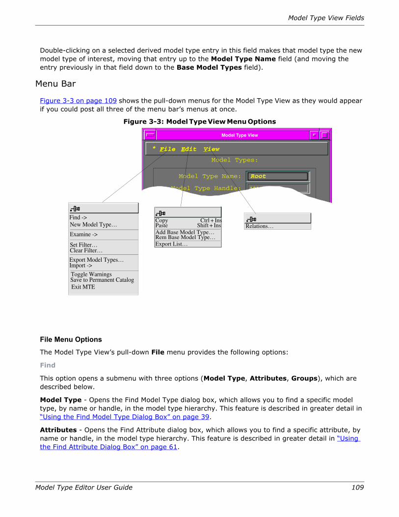
Model Type View Fields
Model Type Editor User Guide 109
Double-clicking on a selected derived model type entry in this field makes that model type the new model type of interest, moving that entry up to the Model Type Name field (and moving the entry previously in that field down to the Base Model Types field).
Menu Bar
Figure 3-3 on page 109 shows the pull-down menus for the Model Type View as they would appear if you could post all three of the menu bar’s menus at once.
Figure 3-3: Model Type View Menu Options
File Menu Options
The Model Type View’s pull-down File menu provides the following options:
Find
This option opens a submenu with three options (Model Type, Attributes, Groups), which are described below.
Model Type - Opens the Find Model Type dialog box, which allows you to find a specific model type, by name or handle, in the model type hierarchy. This feature is described in greater detail in “Using the Find Model Type Dialog Box” on page 39.
Attributes - Opens the Find Attribute dialog box, which allows you to find a specific attribute, by name or handle, in the model type hierarchy. This feature is described in greater detail in “Using the Find Attribute Dialog Box” on page 61.
Base Model Types:
Model Type Handle:
Model Type Name: Root
10000
Model Type View
File Edit View*
Model Types:
Copy Ctrl + InsPaste Shift + Ins
Rem Base Model Type…Add Base Model Type…
Export List…
Find -> New Model Type…
Examine ->
Set Filter…Clear Filter…
Export Model Types…Import ->
Toggle WarningsSave to Permanent CatalogExit MTE
Relations…

110 Model Type Editor User Guide
Chapter 3: The MTE Views
Groups - Opens the Find Groups dialog box, which allows you to find a specific attribute group even if you are unsure where it originated from or the exact spelling of its name. This feature is described in greater detail in “Using the Find Group Dialog Box” on page 68.
New Model Type…
Opens the New Model Type dialog box, which lets you enter a name for a new derived model type based on the current model type (as identified in the Model Type Name field). This feature is described in greater detail in “Creating a Model Type” on page 47.
Examine
This option opens a submenu with three options (Attributes, Derived, Base), which are described below.
Attributes - Opens the Attribute View to show the attributes for the model type currently shown in the Model Type Name field. For further details, refer to “The Attribute View” on page 112.
Derived - Activated when any entry in the Derived Model Types field has been selected (highlighted); refocuses the MTE to the selected derived model type the new model type of interest. That selected name moves to the Model Type Name field, moving the former model type of interest to the Base Model Types field, and with its own next-generation “child” types, if any, becoming listed in the Derived Model Types field.
Base - Activated when any entry in the Base Model Types field has been selected (highlighted), refocuses the MTE to make that selected base model type, making it the new model type of interest. That selected entry moves to the Model Type Name field, its own “parent” model types becomes listed in the Base Model Types field, and all of its own next-generation “child” types becomes listed in the Derived Model Types field.
Set Filter…
Opens the Set Model Type Filter dialog box, letting you enter the name or handle (or any partial character string) as a model type filter. The filter restricts the model types shown in the Derived Model Types field, causing that scroll list to identify only those derived model types that comply with the entry currently set in the filter. To avoid subsequent confusion, clear the filter after using it. The filter is not case-sensitive. For details of filter operation, refer to “Applying the Model Type Filter” on page 43.
Clear Filter…
Clears the current contents of the model type filter, letting the Derived Model Types scroll list show an unrestricted list of all derived model types for the current model type of interest. For further details, refer to “Clearing the Model Type Filter” on page 46.
Export Model Types…
Provided that you have previously designated one or more model types for export by prior use of the Edit > Export List function, opens the Export Model Types dialog box, which lets you select or create an export file and copy the previously selected model types into that export file. As a default user, you can export only those model types, attributes, relations, and rules created with the Default Developer ID. Moreover, there is a real probability that the handles of these objects will conflict with default values existing on any other system to which you might want to export. In addition, the exchange of such objects between systems using a Default Developer ID means that the objects are susceptible to modification or corruption on the receiving system. For these

Model Type View Fields
Model Type Editor User Guide 111
reasons, it is strongly recommended that all users become registered and obtain a registered Developer ID from Aprisma Management Technologies, Inc. Registered developers can export model types, attributes, relations, and rules created with their registered Developer ID, thereby simultaneously avoiding any conflict situations and protecting their creations from accidental or deliberate modification. For more information on exporting model types, refer to “Importing and Exporting Model Types” on page 143.
Import
This option opens a submenu with two options (Model Types, MIB File), which are described below.
Model Types - Opens the Import Model Types dialog box, which lets you import new model types and relations from a file that has been created by use of the MTE export feature (on the same or another system) or by the dbtool utility. Refer to “Importing and Exporting Model Types” on page 143 for more information on importing model types.
MIB File - Opens the Import MIB dialog box, which lets you import new model types and relations from an Internet Standard MIB file based on Simple Network Management Protocol (SNMP). For more information on MIB definition and format, refer to MIB-II (RFC1212 and RFC1155). For more information on importing a MIB, refer to “Importing a MIB” on page 162.
Toggle Warnings
Alternatively turns on and off the warning messages that can be provided by the MTE throughout any operation. These warning messages should be left enabled unless you are thoroughly familiar with all aspects of MTE operation, as their intent is not only to warn you about choices that might lead to loss of data but also to advise you as to how to proceed through certain phases.
Save to Permanent Catalog
Directs the MTE to transfer changes made during the current operating session (added/removed model types, attributes, relations, and/or rules) from the temporary storage provided by the MTE during the operating session to the SPECTRUM database. While a similar function is called if you start to exit from the MTE without having saved your changes, this option lets you transfer those changes without leaving the MTE program.
Exit MTE
Initiates the process of closing down the MTE program following any operator activity. If you have already activated the Save to Permanent Catalog option (see above) or if no actual changes have been made, this selection actually exits from the program immediately. If the temporary storage area contains any interim changes that have not been saved, activation of this option calls the final Save Changes dialog box, which lets you choose between saving those changes, discarding those changes, or returning to the MTE program (see Figure 2-6 on page 38).
Edit Menu Options
The Model Type View’s drop-down Edit menu provides the following options, which you can activate either by clicking the left mouse button in the designated option space or by pressing Return after moving the cursor to the designated space (“Navigating in the MTE” on page 29).
Copy
Copies a group of highlighted characters into the clipboard buffer. Used in conjunction with the associated Paste function to copy the contents of the clipboard into the concurrent cursor location.
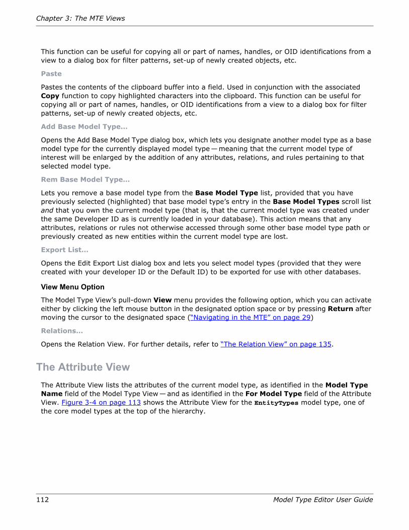
112 Model Type Editor User Guide
Chapter 3: The MTE Views
This function can be useful for copying all or part of names, handles, or OID identifications from a view to a dialog box for filter patterns, set-up of newly created objects, etc.
Paste
Pastes the contents of the clipboard buffer into a field. Used in conjunction with the associated Copy function to copy highlighted characters into the clipboard. This function can be useful for copying all or part of names, handles, or OID identifications from a view to a dialog box for filter patterns, set-up of newly created objects, etc.
Add Base Model Type…
Opens the Add Base Model Type dialog box, which lets you designate another model type as a base model type for the currently displayed model type—meaning that the current model type of interest will be enlarged by the addition of any attributes, relations, and rules pertaining to that selected model type.
Rem Base Model Type…
Lets you remove a base model type from the Base Model Type list, provided that you have previously selected (highlighted) that base model type’s entry in the Base Model Types scroll list and that you own the current model type (that is, that the current model type was created under the same Developer ID as is currently loaded in your database). This action means that any attributes, relations or rules not otherwise accessed through some other base model type path or previously created as new entities within the current model type are lost.
Export List…
Opens the Edit Export List dialog box and lets you select model types (provided that they were created with your developer ID or the Default ID) to be exported for use with other databases.
View Menu Option
The Model Type View’s pull-down View menu provides the following option, which you can activate either by clicking the left mouse button in the designated option space or by pressing Return after moving the cursor to the designated space (“Navigating in the MTE” on page 29)
Relations…
Opens the Relation View. For further details, refer to “The Relation View” on page 135.
The Attribute ViewThe Attribute View lists the attributes of the current model type, as identified in the Model Type Name field of the Model Type View—and as identified in the For Model Type field of the Attribute View. Figure 3-4 on page 113 shows the Attribute View for the EntityTypes model type, one of the core model types at the top of the hierarchy.
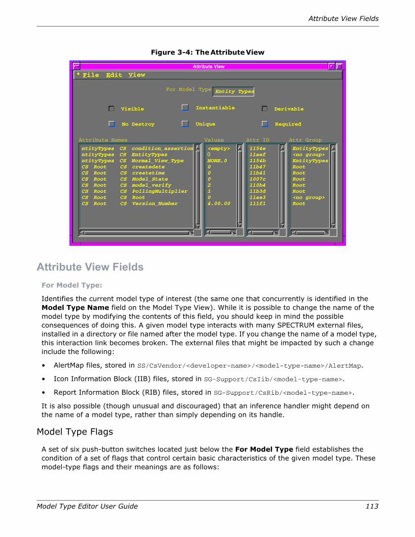
Attribute View Fields
Model Type Editor User Guide 113
Figure 3-4: The Attribute View
Attribute View FieldsFor Model Type:
Identifies the current model type of interest (the same one that concurrently is identified in the Model Type Name field on the Model Type View). While it is possible to change the name of the model type by modifying the contents of this field, you should keep in mind the possible consequences of doing this. A given model type interacts with many SPECTRUM external files, installed in a directory or file named after the model type. If you change the name of a model type, this interaction link becomes broken. The external files that might be impacted by such a change include the following:
• AlertMap files, stored in SS/CsVendor/<developer-name>/<model-type-name>/AlertMap.
• Icon Information Block (IIB) files, stored in SG-Support/CsIib/<model-type-name>.
• Report Information Block (RIB) files, stored in SG-Support/CsRib/<model-type-name>.
It is also possible (though unusual and discouraged) that an inference handler might depend on the name of a model type, rather than simply depending on its handle.
Model Type Flags
A set of six push-button switches located just below the For Model Type field establishes the condition of a set of flags that control certain basic characteristics of the given model type. These model-type flags and their meanings are as follows:
Attribute View
File Edit
Derivable
Required
Instantiable
Unique
Visible
No Destroy
For Model Type:Entity Types
Attribute Names
<empty> 1154e EntityTypes
Values Attr ID Attr Group
<no group>EntityTypesRootRootRootRootRoot<no group>Root
11aef1154b11b4711b411007c110b411b3d11ae3111f1
0NONE.00002104.00.00
ntityTypes CS condition_assertionntityTypes CS EntityTypesntityTypes CS Normal_View_TypeCS Root CS createdateCS Root CS createtimeCS Root CS Model_StateCS Root CS model_verifyCS Root CS PollingMultiplierCS Root CS RootCS Root CS Version_Number
View*

114 Model Type Editor User Guide
Chapter 3: The MTE Views
Determines whether this model type is visible to everyone or only to someone using the same Developer ID under which that model type was created. Visibility affects whether a model type appears in the MTE views and in the Reports utility. When visibility is restricted (turned off), the model type is visible only to someone using the same Developer ID under which the model type was created. Similarly, only someone using that same Developer ID can set or reset this button. The default setting for Visible view fields, which can be seen by all users, is recessed (on).
The MTE uses a special colored font to differentiate the names of non-visible model types from visible model types when they appear in the MTE views. The MTE resource file defines the color used for this differentiation, and you can change it to suit your preferences (refer to “MTE Resources” on page 179.
At the current time, these changes do not affect operation of the SpectroSERVER. Keep in mind, however, that functions in some future release of SPECTRUM may respect the Visible flag and disallow access to non-visible model types.
Determines whether this model type can have models created from it in the SpectroSERVER database. A model type must be instantiable to be listed in SpectroGRAPH’s New Icon dialog box. You can use an instantiable model type to create specific models, but you cannot use a non-instantiable model type for that purpose. Only the developer of the model type can set or reset the Instantiable button—that is, the setting of this button can be changed only on a machine running MTE under the same Developer ID under which the model type was created. The default setting for the Instantiable button is raised (off).
Changing the condition of the Instantiable flag does not affect already existing model types. If you turn off the Instantiable flag after creating any models, those models created prior to that change continue to exist and function just as if the flag were still on.
Visible
Raised (button off) — Model type is visible in Model Type View (using invisiblecolor characters) only to someone using the Developer ID under which this model type was created.
Recessed (button on) — Model type is visible to any developer.
Instantiable
Raised (button off) — Model type is not instantiable; users and inference handlers cannot create new models of this type.
Recessed (button on) — Model type is instantiable; users and inference handlers can create new models of this type.

Attribute View Fields
Model Type Editor User Guide 115
Determines whether this model type can be used as a base model to derive other model types. Only the developer of the model type can set or reset this button. The default setting for the Derivable button is recessed (on).
Changing the condition of the Derivable flag does not affect already existing model types. If you turn off the Derivable flag after creating any model types, the new model types continue to exist and function just as if the flag were still on.
Determines whether the selected model can be deleted by SpectroGRAPH. The default setting is raised (off), allowing the associated model type to be destroyed. If you want a particular model type to be undestroyable, depress the No Destroy button as a new assignment.
Indicates that only one model of the selected type exists in the SpectroSERVER database. The default setting for the Unique button is raised (off).
SPECTRUM checks the Unique flag only as models are being created. If you create several models of this type and then turn the Unique flag off, the previously created models continue to exist and to function properly, but you will not be able to create any further models of this type.
Derivable
Raised (button off) — Model type is not derivable; other developers cannot derive models from this one.
Recessed (button on) — Model type is derivable; other developers can derive models from this one.
No Destroy
Raised (button off) — Model type is destroyable; applications and inference handlers can destroy models of this type.
Recessed (button on) — Model type is not destroyable; SpectroGRAPH will not let inference handlers and applications destroy models of this type.
Unique
Raised (button off) — Model type is not unique; you and/or other developers can create multiple models of this type.
Recessed (button on) — Model type is unique; no additional models of this type can be created.

116 Model Type Editor User Guide
Chapter 3: The MTE Views
Indicates that, if an instance of the selected model type does not exist when SpectroSERVER starts up, one will be created automatically. If you want a particular model type to be created automatically, depress the Required button. The default setting for the Required button is raised (off).
Basic Attribute Modifications
Four scroll-list text blocks arranged horizontally across the lower half of the Attribute View screen provide information about the attributes of the model type currently identified in the For Model Type field at the top of the screen and provide access to associated dialog boxes for making modifications.
Lists the attributes of the selected model type. You cannot edit an Attribute Names entry in the Attribute View screen. The entry actually consists of four separate components (see Figure 2-19 on page 58), with the right-most component being the actual attribute name, and the field is right-shifted so that this attribute name component is always visible. The line entry in a given row is preceded by an asterisk (*) if the given attribute is an external attribute, but you normally must shift the view field to the left side of the text block to see that symbol. In addition, the left-side components of the entry identify the model type from which the given attribute was derived.
If you double-click on the Attribute Names column entry for any given attribute, the MTE opens the Attribute Edit View— exactly as if you had selected the corresponding entry in the Attribute Names field and then selected the File > Open Attribute… option from the menubar. The Attribute Edit View lets you modify various attribute parameters, subject to restrictions of ownership, inheritance. and certain parameter relationships. (You can modify only one attribute at a time.) For further details, concerning this operation, refer to “The Attribute Edit View” on page 121.
Shows the current default values for the associated attributes. The value either is a default value inherited from a base model type or else has been modified for this particular model type. When a model is created from this model type, this value becomes the default attribute value for the new model. If you change the value, the results are determined by the rules of attribute inheritance, but the effects may not be obvious. For further information, refer to “Model Type Inheritance” on page 17.
If you double-click on the Values column entry for any given attribute, the MTE opens the Alter Value dialog box— exactly as if you had selected the corresponding entry in the Attribute
Required
Raised (button off) — Model type is not required and is created only if requested by user, inference handler, or application.
Recessed (button on) — Model type is required; SpectroSERVER will create one model of this type at start-up if a model does not already exist.
Attribute Names
Values
Attribute View Fields
Model Type Editor User Guide 117
Names field and then selected the Edit > Alter Value… option from the menubar. The Alter Value dialog box lets you enter a new default value for that attribute. (You can change the value of only one attribute at a time.) For further details concerning this operation, refer to “Using the Edit Menu to Alter Attribute Characteristics” on page 75, and/or to Figure 2-29 on page 76.
Note: Exceptionally long attribute values will be split and text-wrapped within the Change Attribute Value box. Since the box is preformatted with carriage returns, added characters will not look the way you entered them when the Change Attribute Value box is next displayed, even though your changes will be initiated.
Lists the attribute ID for the attribute associated with a given line entry. The attribute ID is a unique identifier combining the Developer ID resident in the database at the time of the attribute’s creation with a unique hexadecimal sequence number assigned by the MTE as a counter value at that time, as diagrammed in Figure 3-5.
Figure 3-5: Structural Makeup of the Attribute ID
You cannot change Attr ID entries, which never change their unique value. If an attribute is deleted from a model type, its Attribute ID does not get reused.
Shows the name of an attribute group to which the given attribute has been assigned; if the attribute has not been assigned to a group, the entry is <no group>. You can group attributes into a hierarchical structure consisting of attribute groups and individual attributes— with unassigned individual attributes being at the highest level, the attributes and subgroups of any attribute groups at the next lower level, the attributes and subgroups within those subgroups at the next lower level, and so on. These groupings affect the way in which SpectroGRAPH presents attributes in the Attribute Browser display; other SPECTRUM applications, including third-party applications, also may make use of these grouping arrangements.
If you double-click on the Attr Group column entry for any given attribute, provided that the attribute in question was created with the same Developer ID in effect that you are currently using, the MTE opens the Group Attribute List dialog box— exactly as if you had selected the corresponding entry in the Attribute Names field and then selected the Edit > Alter Group… option from the menubar. The Group Attribute List dialog box lets you assign the given attribute to any already existing attribute group by simply selecting in that dialog box the name of the desired group and then clicking on the Ok key— or, even easier, by simply double-clicking on the attribute group name. For further details concerning this operation, refer to Figure 2-38 on page 86.
Either way, you can assign more than one attribute to the same attribute group at one time. To do this with the menubar’s Edit > Alter Group… approach, simply hold down the Control key on
Attr ID
Attr Group
Developer ID Prefix
(4 hexadecimal characters, starting in position 1,
Unique sequence number,
0 x 0 1 2 a e 6
Dev. ID Sequence #
never repeated for same Developer ID)
starting in position 5)
(4 hexadecimal characters,
excluding leading zeros)

118 Model Type Editor User Guide
Chapter 3: The MTE Views
your keyboard and single-click each desired Attribute Names entry in succession and then select the Edit > Alter Group… option.
If you attempt either of these approaches on an attribute that was not created under the same Developer ID that is currently loaded in your SPECTRUM database or on an attribute that has been inherited from a Model Type that was created under a different Developer ID, the Group Attribute List dialog box will not appear. Instead, the MTE will display the Non-Owner Warning message dialog box illustrated in Figure 3-6 on page 118.
Figure 3-6: Error Message Displayed If You Try to Access Group Attribute List Dialog Box for a Model Type You Do Not Own
Menu Bar
The Attribute View has two drop-down menus. Figure 3-7 shows the pull-down menus for the Attribute View menu bar as they would appear if you could post all of these menus at once.
Figure 3-7: Attribute View Menu Options
File Menu Options
The Attribute View’s drop-down File menu provides the following options, which become activated either by clicking the left mouse button in the designated option space or by pressing Return after moving the cursor to the designated space (“Navigating in the MTE” on page 29).
New Attribute…
Opens a special “dummy” version of the Attribute Edit View (see Figure 2-18 on page 57), which lets you create a new attribute for the currently selected model type. The default name for the new
Do you wish to apply your
NonOwner Warning
You cannot change the Group ID of an attributethat you do not own.
Ok Cancel
Attribute View
File Edit
Derivable
Required
Instantiable
Unique
Visible
No Destroy
For Model Type:Entity Types
View*Attribute View
File Edit
Derivable
Required
Instantiable
Unique
Visible
No Destroy
For Model Type: Entity Types
View*
Copy Ctrl+InsPaste Shift+Ins
Alter Value…Rem Attributes…
Alter Group…Alter Flags…
New Attribute…Open Attribute…
Clr FilterSet Filter Name/ID
Save All ChangesClose Attributes
Group…

Attribute View Fields
Model Type Editor User Guide 119
attribute, as initially displayed on the Attribute Edit View screen, is a blank (empty field) and the default Type ID designation is NULL; you must replace these with an acceptable name of your choice and some selectable type designation before you can save the new attribute.
Open Attribute…
Opens the Attribute Edit View (see Figure 3-8 on page 122) for a highlighted attribute previously selected in the Attribute Names field. You can only open one attribute at a time.
Set Filter Name/ID
Opens the Set Attribute Filter dialog box, which lets you enter either the full name or handle identification of any specific attribute or else any partial character string that can be satisfied by any one or more attribute names or handles in the database. The filter restricts the attributes subsequently listed in the Attribute View, meaning that the Attribute View scroll field subsequently lists only those attributes (for the current model type) having names or handles that include the search string; this condition remains in effect until you either change or clear the filter or until you exit from the Attribute View and return to the Model Type View. If you enter a filter identification pertaining to an attribute that has not been established for the current model type of interest, the MTE will change its focus to the highest-ranking model type in the database that does have that attribute, making it the new model type of interest. Filter names are not case-sensitive. Using this feature is covered in “Using the Set Attribute Filter Dialog Boxes” on page 64.
Clear Filter…
Clears (erases) the contents of the attribute filter, allowing the Attribute View subsequently to list all attributes pertaining to the current model type of interest. Since no indication of filter activity is provided other than the restriction of the contents of the scroll list to those attributes that satisfy the filter pattern, it is a good idea to develop the habit of clearing the filter after using it, so as to avoid subsequent confusion. Use of this feature is covered in “Clearing the Attribute Filter” on page 67.
Save All Changes
Saves any changes made to one or more attributes listed in the Attribute View for the current model type of interest and returns to the Model Type View. This saving operation pertains to the Working Catalog cache, which stores information in a temporary storage area that is created by activation of the MTE and remains valid as long as the MTE remains active. When you initiate the sequence for closing down the MTE program by activating the File > Exit MTE option in the Model Type View, you will be asked if you wish to save all such changes to the Permanent Catalog—meaning that portion of the SPECTRUM database in which model-type information is stored. Alternatively, you can transfer data from the Working Catalog storage area to the Permanent Catalog database at any time by activating the File > Save to Permanent Catalog option in the Model Type View.
Close Attributes
Initiates the process of exiting from the Attribute View and returning to the Model Type View. If you have already activated the Save All Changes option (see preceding paragraph) or if no actual changes have been made, this selection actually exits from the Attribute View immediately. If the temporary storage area contains any interim changes that have not been saved, however, activation of this option calls an interim Save Changes dialog box, which lets you choose between saving those changes, discarding those changes, or returning to the Attribute View (see Figure 2-6 on page 38).

120 Model Type Editor User Guide
Chapter 3: The MTE Views
Edit Menu Options
The Attribute View’s drop-down Edit menu provides the following options:
Copy
Copies a group of highlighted characters into the clipboard buffer. Used in conjunction with the associated Paste function, which copies the contents of the clipboard into the concurrent cursor location, this function can be useful for copying all or part of names, handles, or OID identifications from a view to a dialog box for filter patterns, set-up of newly created objects, etc.
Paste
Pastes the contents of the clipboard buffer into a field. Used in conjunction with the associated Copy function, which copies highlighted characters into the clipboard. The Paste function can be useful for copying all or part of names, handles, or OID identifications from a view to a dialog box for filter patterns, set-up of newly created objects, etc.
Rem Attributes…
Initiates the process of removing previously selected attribute(s) from the Attribute Names list — provided that you have selected (highlighted) one or more entries in the Attribute Names scroll list and also that each such selected entry was created under the same Developer ID as is currently loaded into your database and that the attribute in question originates with the current model type. You cannot remove inherited attributes.
Note: Currently, editing another developer’s attribute values, or another developer’s model type, is not guaranteed to survive the next upgrade. You should keep a record of any such change that you make, so that you reapply the change(s) after upgrading to the next version release, if necessary.
Alter Value…
Opens the Alter Value dialog box to let you enter a new default value for a attribute value selected (highlighted) in the Attribute Names or the Values scroll lists. You can change the value of only one attribute at a time. For further details concerning this operation, refer to “Using the Edit Menu to Alter Attribute Characteristics” on page 75 and/or to Figure 2-29 on page 76.
Note: If you do not own a given model type (that is, if it was not created under the Developer ID you are currently using) but attempt to change its Group ID, a notification message will appear in a pop-up window telling you that you cannot do this.
Alter Group…
Opens the Attribute Group List dialog box to let you assign any attribute(s) previously selected (highlighted) in the Attribute Names or the Attr Group scroll lists (hold down the Control key while selecting multiple entries) to any desired attribute group — provided that the attribute(s) was/were created under the Developer ID currently loaded into your database. For further details concerning this operation, refer to “Using the Edit Menu to Alter Attribute Characteristics” on page 75 and/or to Figure 2-34 on page 81.
Note: If you do not own a given model type (that is, if it was not created under the Developer ID you are currently using) but attempt to change its Descriptor flag values, a notification message will appear in a pop-up window telling you that you can only change the value of the Extension flags. If you continue with the change operation, you will receive a pop-up message when you try to confirm any changes, telling you that you cannot make those changes.

The Attribute Edit View
Model Type Editor User Guide 121
Alter Flags…
Opens the Alter Flags dialog box to let you change the settings of Descriptor and Extension flags of any attribute(s) previously selected (highlighted) in the Attribute Names scroll list (hold down the Control key while selecting multiple entries). You can only change the setting of Descriptor flags in the Flags area if the selected attributes were created under the same Developer ID that you are using, but you can change the settings of flags in the Extended Flags area at any time. For further details concerning this operation, refer to “Using the Edit Menu to Alter Attribute Characteristics” on page 75, and/or to Figure 2-35 on page 82.
View Menu Options
The Attribute View’s drop-down View menu provides the following option, which you can activate either by clicking the left mouse button in the designated option space or by releasing the left mouse key after moving the cursor to the designated label space (“Navigating in the MTE” on page 29).
Groups…
Opens the Attribute Group List dialog box, which presents attributes available for a model type, grouped as a hierarchical structure, with unassigned individual attributes at the highest level, attributes in groups at the next-lower level, attributes in subgroups subordinate to those groups at the next-lower level, and so on. While a differently configured version of the Attribute Group List dialog box can be opened from other points in the MTE program for the task of assigning one or more attributes to an existing attribute group, the version you open by clicking on this Groups… button provides capabilities for manipulating attribute group assignments: creating new groups, assigning attribute groups as subordinate subgroups to other attribute groups, deleting unwanted attribute groups (provided that they are empty), and changing the name of attribute groups. For further details concerning these capabilities, refer to “Creating and Managing an Attribute Group” on page 83.
The Attribute Edit ViewEvery attribute is described by a set of characteristics. These descriptions are accessible through the Attribute Edit View shown in Figure 3-8 on page 122. You can access this view by clicking on the Open Attribute… option of the File menu in the Attribute View after selecting an entry in the Attribute Names scroll list (or, alternatively, by double-clicking on that selected entry). The window is divided into two groups of characteristics: Attribute Description in the upper half and Attribute Extended Description in the lower half. The elements in the upper portion are often referred to in SPECTRUM documentation as Descriptor characteristics; the elements in the lower portion are often referred to as Extension characteristics. If you are not the owner of the attribute (that is, if the attribute you are trying to edit was created under some other Developer ID than the one loaded in your database or the current model type is not the one in which this attribute originates), the Attribute Description selections will be grayed out and you will not be allowed to change them, but you will be able to change elements in the Attribute Extended Description area. Several additional flags can be set for an attribute to further describe its characteristics, such as where its value is stored, how its value is initialized, and its access control.

122 Model Type Editor User Guide
Chapter 3: The MTE Views
Figure 3-8: The Attribute Edit View
Since derived model types inherit attributes from base model types, it is possible for more than one model type to have the same attribute. However, the specific attribute settings may differ for each model type. For example, you may want to set the Extended flags for an attribute differently for each model type that uses it. When you set the fields and flags in this view, they apply for the attribute as it is used by the specific model type currently being edited—the current model type, as identified in the For Model Type field of the Attribute View or in the Model Type Name field in the Model Type View.
Attribute Edit View FieldsThe following subsections describe the functions of the fields and options in the Attribute Description area, the Attribute Extended Description area, and the Attribute Edit View menu bar.
Attribute Description Area
The Attribute Description area in the top half of the Attribute Edit view (Figure 3-8 on page 122) lets you establish the name of the attribute under examination (or being created), lets you define the type during the attribute creation process, lets you assign the attribute to a desired attribute group, and lets you set model-type flags that inform the SpectroSERVER of characteristics of this attribute, such as who may access the value and whether the value is part of a list that includes other values. The controls and their functions are as follows:

Attribute Edit View Fields
Model Type Editor User Guide 123
The name of the attribute is an alphanumeric string of up to 128 characters. The assigned name must be unique (within the current model type) for the developer creating the attribute—that is, for anyone using the same Developer ID. You may use the same name used by a different developer, but all names created under a given Developer ID must be different. The name may consist of letters, numbers, underscore (_) characters, and dashes (-). Spaces, punctuation, or other symbols are not allowed. (If you enter a name that has already been used under your current Developer ID, the MTE will abort the operation and display an error message dialog box, as shown in Figure 2-20 on page 58, when you try to save the new attribute after completing all of your entries.)
When you create a new attribute, this field initially is blank. You must set the name to some value (subject to the restrictions listed above) before you will be allowed to save it to the catalog. (If you do not enter an acceptable name, the MTE will abort the operation and display an error message dialog box, as shown in Figure 2-21 on page 59, when you try to save the new attribute, after completing all of your entries.)
Caution: Once the attribute is saved, its type cannot be changed. If the wrong type was selected or if you subsequently determine that a different type is needed instead, you must remove the existing attribute from the database and then create a new one having the correct type selection.
The attribute type defines the kind of data that the value of the current attribute can hold. When you click on the Type button, a popup list of the possible types appears, as illustrated in Figure 3-9 on page 124. If the attribute represents a managed object that is defined in the MIB, its type should be set to correspond to the type defined in the MIB. Otherwise, its type is determined by the developer.
Name
Type NULL

124 Model Type Editor User Guide
Chapter 3: The MTE Views
Figure 3-9: Selecting an Attribute Type for a New Attribute
When you create a new attribute by clicking on the File > New Attribute… option of the Attribute View, the MTE opens the Attribute Edit View with the type initially set to NULL, which is provided for backward compatibility but is not a legal attribute type for new attributes. Accordingly, you must select a legal type designation (see Figure 3-10 on page 125) before clicking on the File > Save & Close Attr Edit button to quit the Attribute Edit view. If you attempt to close the view without changing this NULL type designation, the MTE produces a pop-up dialog box telling you that the attribute type is not valid; closing that box leaves you in the same screen, so that you can select an applicable type designation.
Text String
0
RevisionHistoryName:
Type:
Group ID:
You must enter a different Name designation and select a different Type category (which cannot be changed) before you can save the new attribute.
The Tagged Octet attribute type is currently not supported.
!CAUTION
Click on Group ID button to open Group Attribute List dialog box in order to assign attribute to an attribute group (see Figure 3-11 on page 127).
Click in Name field and replace blank designation with desired attribute name.
List of Values
Single Value
Click on Type button to show popup menu of attribute types.
Alternate-selection switch: change to List of Values option if your new attribute will have multiple values
Display Data: None
NULLBooleanIntegerEnumerationRealDateTime TicksCounterGaugeModel HandleModeltype HandleRelation HandleLandscape HandleAttr IDOctet StringText StringObject IDIP AddrAgent IDTagged Octet64-Bit Unsigned Integer
Integer When you create a new attribute, selector switch is set to default NULL option. You must select a different designation from the popup menu in order to save the attribute.
Integer-based types (Integer, Enumeration, Time Ticks, Counter, and Gauge) can be changed whenever desired; all others are “locked” after being saved the first time.

Attribute Edit View Fields
Model Type Editor User Guide 125
Figure 3-10: Selecting an Attribute Type for an Existing Attribute
When you successfully execute the File > Save & Close Attr Edit function, the program creates the new attribute with the designated name and group designation, assigning a new unique handle to that attribute. This saving function is accomplished in a temporary storage area in RAM, so that you can work with the attribute. The final change is not stored to the Working Catalog, however, until you activate the File > Save All Changes option in the Attribute View.
After you have saved a new attribute, its type aspect is “locked”—meaning that you cannot change it, except in the case of certain integer-based attributes. These exceptions are Integer, Enumeration, Time Ticks, Counter, and Gauge. For any of these, you can return to the Attribute Edit View at any time and click on the Type button again to reopen the popup menu. When you do this, the popup menu contains a longer list of types, as the system recognizes other no-longer-used types for the purposes of backward compatibility, but the only actual choices open to you are the same integer-based types listed above.
Text String
0
RevisionHistoryName:
Type:
Group ID:
The Tagged Octet attribute type currently is not supported.
!CAUTION
List of Values
Single Value
Click on Type button to show popup menu of all recognized attribute types.
You can click on the Group ID button at any time to reassign the current attribute to a different attribute group, if desired (see Figure 3-11 on page 127).
When you create a new attribute, the selector switch will be set to whatever option was last selected. You can select any different designation from the popup menu and then save the attribute with that new selection henceforth in effect.
Display Data: None
NULLBooleanIntegerEnumerationRealDateTime TicksCounterGaugeModel HandleModeltype HandleRelation HandleLandscape HandleAttr IDOctet StringText StringObject IDIP AddrAgent IDTagged Octet64-Bit Unsigned Integer
Integer
Alternate-selection switch becomes locked when new attribute is saved, cannot be changed after that first creation operation.
Integer-based types (Integer, Enumeration, Time Ticks, Counter, and Gauge) can be changed when- ever desired; all others are “locked” after being saved the first time.

126 Model Type Editor User Guide
Chapter 3: The MTE Views
The Group ID button and its associated field, located below the Type field in the Attribute Description area in the Attribute Edit View, pertain to the attribute group assignment of the attribute under examination. The field contains the attribute identifier for the attribute group to which this attribute currently belongs. If the adjacent field value is 0 (zero), the attribute is not part of a group; this means that it will be designated as <no group> in the Attr Group scroll list in the Attribute View. Clicking on the Group ID button opens the Group Attribute List dialog box, as shown in Figure 3-11 on page 127, and you can then assign the attribute to any desired attribute group.
Caution: If you use another developer’s attribute or attribute group as the attribute group for an attribute, and that developer’s attribute/attribute group is not distributed with the next release/upgrade, your attribute’s group value will be set to the default 0 (zero) value and the Attr Group entry in the Attribute View will be changed to the default <No Group> value.
The Group Attribute List dialog box presents attributes and attribute groups available for a model type as a hierarchical structure, arranged in alphabetical order, with the attribute group names indicated by a dark background. All attributes that are not assigned to attribute groups are presented at the top level (flush left in the Group/Attributes field), with these entries and all first-level groups listed in alphabetical order. Within each group, this same pattern continues, with attributes and secondary-level attribute groups being listed in alphabetical order and indented slightly to the right, with the same indentation and alphabetical arrangement being repeated for each successive subgroup.
Figure 3-11 on page 127 shows the Attribute Group List dialog box that appears when you click the Group ID button. The Group/Attributes scroll field in the upper part of this dialog box lists both attribute groups and attributes, with the latter indented under the attribute group to which each is assigned (or, if not currently assigned to any attribute group, set flush left in the list).
If you access the Attribute Group List dialog box from the Attribute Edit View in this manner after accessing the Attribute Edit View by clicking on the Attribute View’s File > New Attribute… option, the Group/Attributes list will not yet include the name of the new attribute which you are creating, as it does not exist until it has been saved. You can assign that new attribute to any attribute group of your choice at this time, however, by (1) clicking on (highlighting) the entry for the group to which you wish to assign your new attribute and then (2) clicking on the Ok button—or, even more simply, by just double-clicking on the attribute group entry. When you do this, the Attribute Group List dialog box goes away, returning you to the Attribute Edit View. When you close out of that view by selecting any one of the Save & Close exit paths, you will find the new attribute listed in its proper place in the Attribute Names field of the Attribute View, with the just-selected attribute group listed in the Attr Group column.
Group ID

Attribute Edit View Fields
Model Type Editor User Guide 127
Figure 3-11: Using the Attribute Group List Dialog Box to Assign New Attribute to an Attribute Group
If you access the Attribute Group List dialog box by clicking on the Attribute Edit View’s Group ID button after opening the Attribute Edit View either by clicking on the Attribute View’s File > Open Attribute… option or by double-clicking an Attribute Names entry in the Attribute View, the previously selected attribute will be listed in the Group/Attributes field, either as an unassigned (flush left) attribute or within one of the existing attribute groups.
The procedure for assigning this existing attribute is the same, however: (1) click on (highlight) the Group/Attributes entry for the attribute group to which you wish to assign the existing attribute and then (2) click on the Ok button— or just double-click on the attribute group entry. When you do this, the Attribute Group List dialog box goes away, returning you to the Attribute Edit View. You many notice in the background that the Attr Group field in the Attribute View still shows the previous assignment (<no group> a different group, as applicable)— because, again, the change has not yet been saved to memory. When you close out of the Attribute Edit View by selecting any one of the Save & Close exit paths, however, the just-selected attribute group name will appear in the Attr Group column.
Group Attributes
Attribute Group List
CancelOk
Explode All
Collapse AllCollapse
Explode
Clear Group
GlobalMFragNotesgib_mtype_namegib_mtype_name_menugib_model_namegib_model_name_menu
AutoDiscoveryADiscClassFrag
ConnectionPrecDataRelayClassGeneralDiscClass
ADiscDRelayRepADiscDataRelayMH
CommonInfoDescriptionSystem_Up_TimeContactPerson
GlobalMFrag
AutoDiscovery
ADiscDRelayRep
CommonInfo
System_Up_Time
Attributes and subgroups within a group are indented under the group name.
Attribute group names are identified by colored bands across screen.
To assign the current attribute to a group, select the desired group name and then click on the OK button.
To remove an attribute from a currently assigned group, select the attribute name and then click on the Clear Group button.

128 Model Type Editor User Guide
Chapter 3: The MTE Views
Several buttons available in the Attribute Group List View let you explore the attribute group hierarchy by exploding or collapsing different groups. The names of attribute groups on the list are designated by use of a different background color than individual attributes. When a group is exploded, the attributes and/or subgroup names appear indented from the parent group on the list—and entries in subgroups are indented even further, to provide quick visual identification of the hierarchal structure. For further information on these buttons or other capabilities of the Group Attribute List dialog box, refer to “Creating and Managing an Attribute Group” on page 83.
Attribute Description Flags
Attribute Description flags, shown at the top-right side of the view in Figure 3-8 on page 122, inform SpectroSERVER of characteristics of this attribute, such as who may access the value and whether the value is part of a list that includes other values. The flags are not used by the MTE, but the MTE is the tool that lets you set and reset the flags. Attribute Description flags, also called Descriptor flags in SPECTRUM documentation, can be changed only by an MTE user working with the same Developer ID under which the attribute was created and in the originating model type. Certain combinations of flags have override requirements, as delineated in Table 3-1 on page 129. The flags and their functions are as follows:
Indicates that the value for this attribute is maintained outside of SpectroSERVER and that update of the attribute value is done either at a user request or at a polling interval.
Informs SpectroSERVER that a client or other application is allowed to read this attribute value from SpectroSERVER. If the External flag is set, you should set this flag in accordance with the MIB definition of the Readable variable for this attribute. If the External flag is not set, you can set this flag as desired.
External
Readable

Attribute Edit View Fields
Model Type Editor User Guide 129
Table 3-1: Overriding Relationships for Attribute Descriptor Flags and Extended Flags
Informs SpectroSERVER that a client or other application is allowed to write this attribute value to the SpectroSERVER database. If the External flag is set, you should set this flag in accordance with the MIB definition of the Writable variable for this attribute. If the External flag is not set, you can set this flag as desired.
Writable
External
Readable
Writable
SharedGuaranteed
Global
Preserve Value
Memory
Database
Polled
Logged
Ext
erna
l
Rea
dabl
e
Wri
tabl
e
Shar
ed
Gua
rant
eed
Glo
bal
Pre
serv
e V
alue
Mem
ory
Dat
abas
e
Pol
led
Log
ged
Descriptor FlagExtended
Ext
ende
dD
escr
ipto
r F
lag
X X
X
X
X
X
XM
X
O
O
O D
D
D
M – Mandatory:When flag in horizontal row is set (button recessed), flag in the vertical column must also be set.
X – Mutually Exclusive:When flag in horizontal row is set (button recessed), flag in vertical column cannot be set.
– Optional/Mandatory:When flag in horizontal row is set (button recessed), one of two flags in paired vertical columns must be set. For the Attribute Edit View or the Alter Flags dialog box, the D indicates that the corresponding flag (Database) is set by default when flag identified by horizontal row is set, and the O indicates that you can choose to set the corresponding flag (Memory) in addition to or in place of that default setting.
(blank) – Fully optional, with no overriding relationship.
O D
Flag
Fla
g

130 Model Type Editor User Guide
Chapter 3: The MTE Views
Declares that only one value exists for this attribute and that all models of the current model type share the same value. The value is not duplicated in memory or the database for each model.
Note: If an attribute’s Guaranteed flag is off, Extended flags can be toggled on or off. If the Guaranteed flag is on, users having Developer IDs other than the one used to create the attribute can only toggle Extended flags on, not off. The user having the Developer ID used to create the attribute can toggle Extended flags on or off anytime.
Guarantees that this attribute will continue to exist and can be used in future model type derivations. When set, this flag cannot be turned off except by the developer who created the attribute. Note that the values for the attribute are not guaranteed; only the presence of the attribute is guaranteed.
Note: The Global Flag is not used in Distributed SpectroServer (DSS) databases.
Indicates that the global attributes of a model type which is derived from a duplicate model type are maintained and consistent across any and all landscapes in which that model type exists. These global attributes are maintained for User and User-Group models only.
Indicates that imported files will not overwrite the attribute value currently stored in the database. If you customize certain model types for specific requirements of your system and then set this flag, those changed values will remain in place when database model types are updated by subsequent release revisions.
Attribute Extended Description Fields
Attribute Extended fields are located in the lower half of the Attribute Edit view and can be altered by any MTE user (Figure 3-8 on page 122) if the Guaranteed flag is off. When the Guaranteed flag is set (button recessed), anyone can set the Extended flags on but only an MTE user with the same Developer ID as was used to create the attribute can turn those flags off. The following subsections define the function and use of the fields in the Attribute Extended Description area:
When attributes are grouped to form an attribute polling group, this field identifies the attribute group to which they belong. You can create up to 256 polling groups for each model type. Each polling group is identified by a number from 0 (zero) through 255. By default, polling groups are automatically identified with the number 0 (zero), meaning that they are unassigned and will not get polled. Attributes within a group are polled together and logged together. SpectroSERVER polls groups of pollable attributes, each in turn.
Note: f you attempt to enter an erroneous attribute value, a pop-up warning window will appear with a message in the following format:
Error adding new attr value for attr:
10045 CS NETMONITOR Mon_Precedence
Shared
Guaranteed
Global
Preserve Value
Polling Group

Attribute Edit View Fields
Model Type Editor User Guide 131
Caution: For best performance, you should keep the number of polling groups per model type below 16, the maximum number that the SpectroSERVER Statistics Log can store.
When attributes are polled but not logged (Polled flag set, Logged flag not set) the only limit to the number of attributes within a group is the transmission length limits imposed by:
• Transmission protocol (Ethernet, FDDI, etc.)
• Management protocol (Aprisma proprietary, SNMP, etc.)
and
The OID Prefix and OID Ref characteristics apply only to External-type attributes which represent a managed variable within a table in the MIB. Together they define a complete object identifier (OID) for the variable being monitored, as shown in Figure 3-12 on page 131.
Figure 3-12: Structural Makeup of an Object Identifier (OID)
• The OID Prefix characteristic specifies the column within the table that contains the variable. You must use dotted-decimal notation when entering the OID Prefix (see Figure 3-12 on page 131).
• The OID Ref characteristic specifies the name of an attribute, whose value serves as an index used to define the instance of the variable within the column. You must use the attribute name format shown in Figure 3-13 on page 132 to enter an OID Ref entry.
The OID Prefix is concatenated with the attribute value specified by the OID Ref (Instance ID). Figure 3-12 on page 131 illustrates the mechanics of this OID construction. (A managed variable does not always require an OID Ref; you can enter a complete OID with Instance ID into the OID Prefix field.)
OID Prefix
OID Ref
1 . 3 . 6 . 1 . 4 . 1 . 45 . 1 . 3 . 2 . 3 . 1. 2 . 4
OID Prefix
OID Prefix:
OID Ref:
1.3.6.1.4.1.45.1.3.2.3.1
2 . 4
CS EnetHub CS BdPt
CS EnetHub CS BdPt
Instance ID
OID for EnetPortColls
SpectroSERVER Database
ResultingOID
Attribute Edit View
Attribute ID of an
Instance ID.
internal attribute,defining the

132 Model Type Editor User Guide
Chapter 3: The MTE Views
Figure 3-13: Structural Makeup of the OID REF Entry
Extended Flags
Any MTE user can change Attribute Extended Flags (see Figure 3-8 on page 122), subject to the provisions outlined in Table 3-1 on page 129, provided that the Guaranteed Descriptor flag is not set. If the Guaranteed flag is set (recessed), any user can set any Extended flag on (recessed), but only an MTE user working with the same Developer ID under which the current attribute was created can turn those flags off (button raised). These flags and their function (when recessed) are as follows:
Stores a copy of the attribute value in memory. The value will not be preserved upon a SpectroSERVER restart, but will be reset to the default value.
Stores a copy of the attribute value in the database so that it will be preserved across SpectroSERVER restarts .
Informs SpectroSERVER that this attribute should be polled at the polling interval (this is only meaningful if the External flag also is set). The attribute value is updated by each SpectroSERVER poll. If the Memory flag is also set for this attribute, the value retrieved by the poll is also stored in memory.
• If the Polled flag is set, you should assign the attribute to an appropriate polling group; all attributes of a polling group are polled together.
• If the Polled flag is set and the Logged flag is also set for the attribute, you must group the attribute with other attributes that also have their Polled and Logged flags set.
Causes the value of the attribute to be recorded in the SpectroSERVER Statistics Log. You can flag up to 16 individual attributes or attribute polling groups in a model type for logging.
• Logging occurs at a user selected logging interval. The logging interval is stored as the value of an attribute named POLL_TO_LOG_RATIO.
Memory
Database
Polled
Logged
CS Component CS Component_OID
Developer ID Prefix for model type (8 characters, starting in position 1)
Model Type (128 characters, starting in position 9)
Attribute Name (128 characters, starting in position 145)Developer ID Prefix for attribute (8 characters, starting in position 137)

Attribute Edit View Fields
Model Type Editor User Guide 133
• Special consideration must be given to logged attributes. Attributes with only their Logged flags set must be grouped together. Refer to “Polling Group” on page 130 for more information on grouping logged attributes.
• External attributes that are set to be polled/logged may return “noSuchName” errors when a management module is based on a more current firmware version than the managed device supports. To reduce unnecessary network traffic, SPECTUM automatically suspends normal polling and logging for attributes that return this error, and moves the attribute to the unsupported polling attribute group.
Once an attribute has been moved to the unsupported polling attribute group, SPECTRUM generates an event (0x00010970). By default, this event is not logged and does not generate an alarm. However, you can change this event processing by modifying the SPECROOT/CsVendor/Cabletron/EventDisp file. SPECTRUM attempts to read the attribute at the interval specified by the unsupported_attr_poll_interval. By default, the value of the unsupported_attr_poll_interval is 12 hours. This value can be changed by adding the parameter and the desired interval (in seconds) to SPECTRUM’s .vnmrc file. When an attribute that had previously been reporting a “noSuchName” error reports a successful poll, SPECTRUM generates an event (0x00010971). By default this event is not logged and does not clear an alarm. However, you can also change this event processing by modifying the SPECROOT/CsVendor/Cabletron/EventDisp file.
Thus, the unsupported_attr_poll_interval allows normal polling/logging for an attribute to resume automatically without requiring a SpectroSERVER restart or the destruction and recreation of the models with that attribute.
See the Defining SPECTRUM Resources (2559) guide for more information on the unsupported_attr_poll_interval. See the Event Configuration Files Guide (5070) for more information on modifying an EventDisp file.
Menu Bar
Figure 3-14 on page 134 shows the menus for the Attribute Edit View menu bar as they would appear if you could post both of the menus at once.

134 Model Type Editor User Guide
Chapter 3: The MTE Views
Figure 3-14: Attribute Edit View Menu Bar
File Menu Options
The Attribute Edit View’s pull-down File menu provides the following two options. You can activate these options either by clicking the left mouse button in the designated option space or by pressing Return after moving the cursor to the designated space (see Figure 3-14 on page 134).
Save & Close Attr Edit
Saves any edits made to the attribute descriptions in the Attribute Edit View to a temporary storage area in RAM, so that you can evaluate the effect of different settings. The changes are not saved to the Working Catalog until you select the File > Save All Changes option in the Attribute View.
Close Attr Edit
Exits from the Attribute Edit View and returns to the Attribute View, discarding any interim changes made to the attribute descriptions while the Attribute Edit View was open.
Edit Menu Options
The Attribute Edit View’s pull-down Edit menu provides the following two options. You can activate these options either by clicking the left mouse button in the designated option space or by pressing Return after moving the cursor to the designated space (see “Navigating in the MTE” on page 29).
Copy
Copies a group of highlighted characters into the clipboard buffer. Used in conjunction with the associated Paste function, which copies the contents of the clipboard into the concurrent cursor location, this function can be useful for copying all or part of names, handles, or OID identifications from a view to a dialog box for filter patterns, set-up of newly created objects, etc.
Paste
Pastes the contents of the clipboard buffer into a field. Used in conjunction with the associated Copy function, which copies highlighted characters into the clipboard, this function can be useful for copying all or part of names, handles, or OID identifications from a view to a dialog box for filter patterns, set-up of newly created objects, etc.
Attribute Edit View* File Edit
NULL
Name:
Type:Flags:
External
Readable
Writable
Shared
Guaranteed
Global
Attribute Description
Single Value
Preserve Value
Save & Close Attr EditClose Attr Edit
CopyPaste
Ctrl+InsShift+Ins
The Relation View
Model Type Editor User Guide 135
The Relation ViewThe Relation View, shown in Figure 3-15 on page 136, lists the relationships that can exist between model types. The knowledge base supplied with the basic SPECTRUM package contains a number of predefined relations (some of which are provided without rules, which you can add as needed). These relations provide a framework that can replicate most characteristics of a network system. Each relation contains a series of rules that apply the relation to various model types. The MTE lets you “browse” through the existing relations and examine the rules that specify for the given model type what model types take part in a relation. The Relation View also provides access to the Meta-Rule View (see “Open Relation” on page 138).
You access the Relation View by selecting the View > Relations option in the Model Type View.
Relation View FieldsThe Relation View consists simply of the following two scroll-list text blocks, and a pull-down menu bar.
Relation Name
The left-hand text block in the Relation View provides a name entry for each relation that has been defined for the current model type of interest (as identified in the Model Type Name field in the associated Model Type View). The following list identifies all current relations recognized by the SPECTRUM knowledge base as provided with the basic SPECTRUM package, together with their definitions. You can create new relations, if desired, but any relation names you assign must be unique among the relations created under your Developer ID.
Application — A many-to-many relation.
Can_Assign — A one-to-many relation. Relates troubleshooters to users.
Collects — A one-to-many relation. Relates topology hierarchy models.
Connects_to — A many-to-many relation. Relates topology hierarchy models.
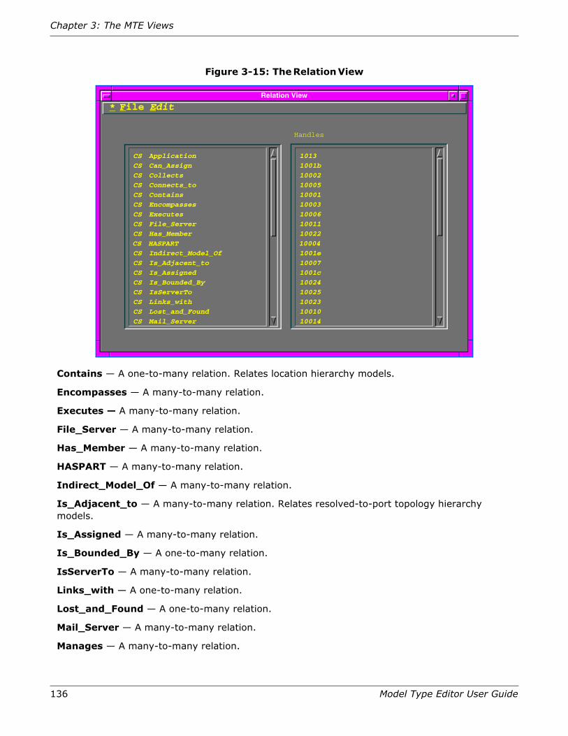
136 Model Type Editor User Guide
Chapter 3: The MTE Views
Figure 3-15: The Relation View
Contains — A one-to-many relation. Relates location hierarchy models.
Encompasses — A many-to-many relation.
Executes — A many-to-many relation.
File_Server — A many-to-many relation.
Has_Member — A many-to-many relation.
HASPART — A many-to-many relation.
Indirect_Model_Of — A many-to-many relation.
Is_Adjacent_to — A many-to-many relation. Relates resolved-to-port topology hierarchy models.
Is_Assigned — A many-to-many relation.
Is_Bounded_By — A one-to-many relation.
IsServerTo — A many-to-many relation.
Links_with — A one-to-many relation.
Lost_and_Found — A one-to-many relation.
Mail_Server — A many-to-many relation.
Manages — A many-to-many relation.
Relation View
File Edit
CS Application
CS Can_Assign
CS Collects
CS Connects_to
CS Contains
CS Encompasses
CS Executes
CS File_Server
CS Has_Member
CS HASPART
CS Indirect_Model_Of
CS Is_Adjacent_to
CS Is_Assigned
CS Is_Bounded_By
CS IsServerTo
CS Links_with
CS Lost_and_Found
CS Mail_Server
Handles
1013
1001b
10002
10005
10001
10003
10006
10011
10022
10004
1001e
10007
1001c
10024
10025
10023
10010
10014
*
Relation View Fields
Model Type Editor User Guide 137
Monitors — A many-to-many relation.
Organizes — A one-to-many relation. Relates organization hierarchy models only.
Other_Server — A many-to-many relation.
Owns — A one-to-many relation. Relates organization hierarchy models to location and topology models.
Passes_Through — A many-to-many relation.
PolyMorph — A one-to-many relation. Relates general model types to specific model types.
Print_Server — A many-to-many relation.
Provides — A one-to-many relation.
Seems_Adjacent_To — A many-to-many relation. Relates unresolved-to-port topology hierarchy models.
PossPrimApp — A one-to-many relation.
PULLED_BOARD — A many-to-many relation.
USES — A one-to-many relation.
USING — A many-to-many relation.
project_contains — A one-to-many relation.
Pings_Through — A one-to-many relation.
Has_Filters — A one-to-many relation.
Is_Associated_With — A one-to-many relation.
Has_Relay_Function — A one-to-many relation.
EMSManges — A many-to-many relation.
InEMSMap — A many-to-many relation.
Presents — A many-to-many relation.
Handle
The right-hand text block in the Relation View identifies the MTE-assigned handle for each relation listed in the Relation Name block. The MTE assigns a unique handle, which cannot be modified, to each relation. A handle is never reused, even after the relation is destroyed. These handles are a different subset from those used by model types and attributes, even though the nomenclature is the same.
Menu Bar
Figure 3-16 on page 138 shows the menu options of the Relation View menu bar as they would appear if you could post all three of its menus at once.
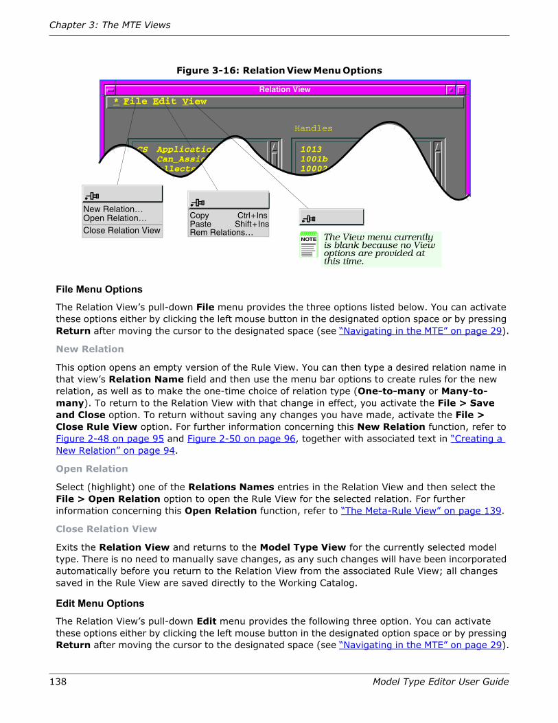
138 Model Type Editor User Guide
Chapter 3: The MTE Views
Figure 3-16: Relation View Menu Options
File Menu Options
The Relation View’s pull-down File menu provides the three options listed below. You can activate these options either by clicking the left mouse button in the designated option space or by pressing Return after moving the cursor to the designated space (see “Navigating in the MTE” on page 29).
New Relation
This option opens an empty version of the Rule View. You can then type a desired relation name in that view’s Relation Name field and then use the menu bar options to create rules for the new relation, as well as to make the one-time choice of relation type (One-to-many or Many-to-many). To return to the Relation View with that change in effect, you activate the File > Save and Close option. To return without saving any changes you have made, activate the File > Close Rule View option. For further information concerning this New Relation function, refer to Figure 2-48 on page 95 and Figure 2-50 on page 96, together with associated text in “Creating a New Relation” on page 94.
Open Relation
Select (highlight) one of the Relations Names entries in the Relation View and then select the File > Open Relation option to open the Rule View for the selected relation. For further information concerning this Open Relation function, refer to “The Meta-Rule View” on page 139.
Close Relation View
Exits the Relation View and returns to the Model Type View for the currently selected model type. There is no need to manually save changes, as any such changes will have been incorporated automatically before you return to the Relation View from the associated Rule View; all changes saved in the Rule View are saved directly to the Working Catalog.
Edit Menu Options
The Relation View’s pull-down Edit menu provides the following three option. You can activate these options either by clicking the left mouse button in the designated option space or by pressing Return after moving the cursor to the designated space (see “Navigating in the MTE” on page 29).
Relation View
File Edit
CS ApplicationCS Can_AssignCS CollectsCS Connects_to
CS Contains
Handles
10131001b1000210005
10001
*
NOTE The View menu currentlyis blank because no Viewoptions are provided at this time.
View
New Relation…Open Relation…Close Relation View
CopyPasteRem Relations…
Ctrl+InsShift+Ins
The Meta-Rule View
Model Type Editor User Guide 139
Copy
Copies a group of highlighted characters into the clipboard buffer. Used in conjunction with the associated Paste function, which copies the contents of the clipboard into the concurrent cursor location, this function can be useful for copying all or part of names, handles, or OID identifications from a view to a dialog box for filter patterns, set-up of newly created objects, etc.
Paste
Pastes the contents of the clipboard buffer into a field. Used in conjunction with the associated Copy function, which copies highlighted characters into the clipboard, this function can be useful for copying all or part of names, handles, or OID identifications from a view to a dialog box for filter patterns, set-up of newly created objects, etc.
Rem Relations…
Opens a Cut List dialog box that lets you remove selected relations from the current model type, provided that you have previously selected (highlighted) one or more Attribute Name entries in the Relation View (hold down Control while selecting multiple entries) and that you have rights to do so. You cannot remove relations (or rules) that were not created under the Developer ID currently loaded into your database.
View Menu Options
No View-menu options are currently available for the Relation View. Although presently blank and without function, this menu field appears as part of the primary view, so as to maintain visual consistency among the views.
The Meta-Rule ViewSpectroSERVER uses relations to describe how one model type interacts with another. Meta-Rules help to define these relationships. The meta-rules that apply to a particular relation are accessible through the Meta-Rule View, as shown in Figure 3-17 on page 140. To access this view, focus the Model Type View on a specific model type and select the View > Relations option to access the Relation View, as discussed in “The Relation View” on page 135. You then can select any desired relation (by name or handle) in that view and either double-click on that entry or else select the File > Open Relation option from its tool bar. Either way, the MTE opens the Meta-Rule View, as shown in Figure 3-17 on page 140.

140 Model Type Editor User Guide
Chapter 3: The MTE Views
Figure 3-17: The Meta-Rule View
Meta–Rule View Controls and IndicatorsOther than the menu bar, the Meta-Rule View contains only one identifier field, one selector button, and a scroll-list field, as follows:
Relation Name
Identifies the relation whose meta-rules are being displayed.
Relation Type
Lets you choose one of two relation types and indicates whichever type currently is selected. You cannot change a relation type after a selection has been saved (effective since Release 4.0). There are two types of relations:
• One-to-many
Indicates that the relation is one model type relating to many other model types.
• Many-to-many
Indicates that the relation is many model types relating to many model types.
Meta–Rule View
File Edit
CM MMACPlus
CS Building
CS Building
CS Building
CS Country
CS Country
CS Country
CS Floor
CS Floor
CS Location
CS Panel
CS Panel
CS Panel
CS Rack
Relation Name:
CM MMPModuleFrag
CS Floor
CS Room
CS Section
CS Building
CS Region
CS Site
CS Room
CS Section
CS Landscape
CM MMACPlus
CS Device
CS Physical_Addr
CM MMACPlusCS Rack CS Device
Relation Type:
Contains
One-to-many
Meta–Rules
*
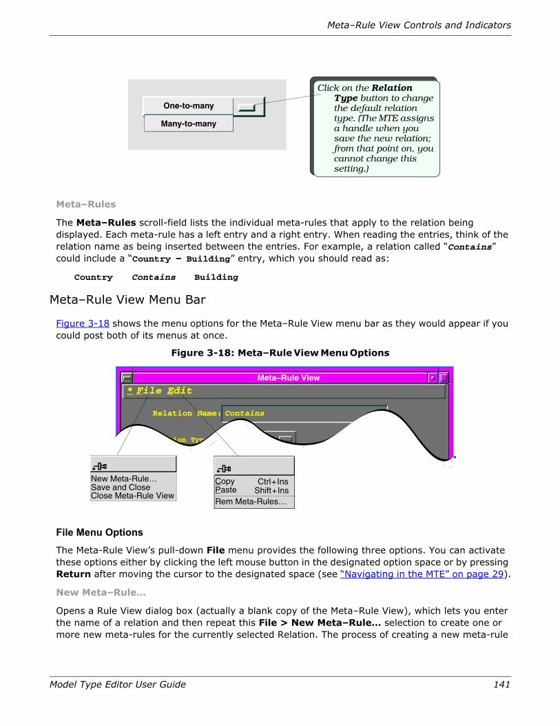
Meta–Rule View Controls and Indicators
Model Type Editor User Guide 141
Meta–Rules
The Meta–Rules scroll-field lists the individual meta-rules that apply to the relation being displayed. Each meta-rule has a left entry and a right entry. When reading the entries, think of the relation name as being inserted between the entries. For example, a relation called “Contains” could include a “Country – Building” entry, which you should read as:
Country Contains Building
Meta–Rule View Menu Bar
Figure 3-18 shows the menu options for the Meta–Rule View menu bar as they would appear if you could post both of its menus at once.
Figure 3-18: Meta–Rule View Menu Options
File Menu Options
The Meta-Rule View’s pull-down File menu provides the following three options. You can activate these options either by clicking the left mouse button in the designated option space or by pressing Return after moving the cursor to the designated space (see “Navigating in the MTE” on page 29).
New Meta–Rule…
Opens a Rule View dialog box (actually a blank copy of the Meta–Rule View), which lets you enter the name of a relation and then repeat this File > New Meta–Rule… selection to create one or more new meta-rules for the currently selected Relation. The process of creating a new meta-rule
Click on the Relation Type button to change the default relation type. (The MTE assigns a handle when you save the new relation; from that point on, you cannot change this setting.)
Many-to-many
One-to-many
Meta–Rule View
File Edit
Relation Name:
Relation Type:
Contains
One-to-many
Meta–Rules
*
New Meta-Rule…Save and CloseClose Meta-Rule View
CopyPasteRem Meta-Rules…
Ctrl+InsShift+Ins

142 Model Type Editor User Guide
Chapter 3: The MTE Views
is detailed in the sequence shown in Figure 2-50 on page 96 through Figure 2-52 on page 98, You can also refer to “Creating a Meta–Rule” on page 101.
Save and Close
Saves and closes the Rule View and returns to the Relation View.
Close Meta–Rule View
Closes the Meta–Rule View without saving any changed settings, returning to the Relation View.
Edit Menu Options
The Meta-Rule View’s pull-down Edit menu provides the following three options. You can activate these options either by clicking the left mouse button in the designated option space or by pressing Return after moving the cursor to the designated space (“Navigating in the MTE” on page 29).
Copy
Copies a highlighted character string.
Paste
Pastes the contents of the clipboard buffer (as obtained by previous activation of the Copy function) into a field.
Rem Meta–Rules…
Removes a previously highlighted entry from the view.

143
Chapter 4: Importing and Exporting Model Types
This chapter describes MTE options and tools that you can use to:
1. Import and export model types using the MTE (together with procedures for importing and/or exporting model types or analyzing the contents of export files by use of the dbtool utility);
2. Import a MIB (Management Information Base) file to be used as the basis for a new or customized model type.
Importing and Exporting Model TypesAs your network grows, you may need to add new management modules and model types to your database. Moreover, you may want to add these new model types to your database without installing a completely new database, so that you can keep intact all of the model types you have created or modified. Two database utilities allow you to import and export model types.
• mte, which has import and export functions that use MTE menu selections and views.
• dbtool, which is invoked at the Unix command level.
While both tools serve the same function, the dbtool utility is probably the more useful if you want to batch-process a series of many separate imports or exports, whereas the MTE is the more useful if you just want to import or export one or two files.
In either case, the transfer vehicle is a binary export file, having an .e extension. Most *.e files include all of the database information that the MTE enters into a database relevant to a number of model types (including not only any new model types but also all model types on which those new ones depend). These export files are therefore referred to as catalogs, even if the file only contains the information for a single model type.
Caution: Keep in mind that database access must be limited to only one application at a time. When either mte or dbtool is in use, all other applications (including SpectroSERVER) must be denied access. While Aprisma-developed programs automatically lock out other Aprisma products, corruption of the database can occur if this caution is ignored or bypassed with respect to any third-party application programs.

144 Model Type Editor User Guide
Chapter 4: Importing and Exporting Model Types
Unless you have specified a different directory in your system search path, the specific database tool being used (mte or dbtool) must be run from the same directory as the SpectroSERVER database. Both mte and dbtool create a file named .VNMDB.LOCK to lock the database, preventing concurrent access from other application programs. Refer to SPECTRUM Database Management for more details.
Using the MTE to Import Model Types
Constraints
New model types can be imported using the MTE, subject to the following constraints:
• When the catalog file being imported contains a model type that does not currently exist in the database, the importation process adds that model type (subject to the remaining restrictions in this list).
• All base model types for any new model type(s) must already exist in your database. If the base model types do not currently exist in your database, they must be imported first. (Normally, the “core catalog” contains these prerequisite model types, and documentation accompanying any new catalog informs you of any such dependencies.)
• When the import file contains a model type that already exists in the database, the import process overwrites the existing model type, making the on-line template a match for the model type being imported. This includes:
• The program changes model type derivation links that are different from the version in the catalog being imported.
• The program adds any included attributes that do not currently exist in the database.
• The program modifies existing attributes to match the model type attributes being imported.
• The program deletes otherwise unused attributes associated with the same Developer ID as the original model type that are not in the imported model type (that is, any such attributes become disinherited, if the imported model type does not include them and no other model type in your database includes them).
• If an error occurs during the import process because a prerequisite model type is found not to exist in the database into which some model type that depends on that missing model type is being imported, the import process terminates. This event activates an error message reporting that a base model type is missing. If this occurs, you must:
• Determine what base model type you need.
• Import a catalog containing the missing model type(s).
• Reinitiate the same import process for the catalog of interest.
• If an error occurs during the import process because of a write error to the destination database or because memory or resources are insufficient, the process terminates with an appropriate error message. Since this situation may leave the database in an incomplete or corrupted state, you should back up your database prior to starting this import process.

Using the MTE to Import Model Types
Model Type Editor User Guide 145
Importing a Catalog
To import the contents of a catalog into your database, proceed as follows:
Caution: While the MTE lets you make the final decision as to whether or not imported data is actually placed in the permanent catalog (so long as you keep warnings enabled), there is always a danger that problems might occur during an import process, and thus that your database could be corrupted. To be safe, always make a backup of your database before performing an import operation. Refer to How to Manage Your Network with SPECTRUM and SPECTRUM Database Management for further information about backing up your database, database tools, and maintenance of your database.
Note: Following completion of this procedure, the imported model types are stored in your Working Catalog and are available for your use. When you subsequently save all changes, as part of the normal process of shutting down the MTE at the end of the current operational activity, these imported model types will be copied into your permanent Master Catalog in the SPECTRUM area as permanent entities in your system.
1. Determine the path and filename for the file containing the model types you want to import. (The filename was assigned when the model types were exported at their source; the path depends on the distribution media and whether or not you have already copied the catalog onto your system.)
2. Open the Model Type View and select the Import > Model Types… option in the File menu. The Import Model Types dialog box appears, as shown in Figure 4-1 on page 146.

146 Model Type Editor User Guide
Chapter 4: Importing and Exporting Model Types
Figure 4-1: Import File Dialog Box
3. In that dialog box, either replace the default Selection field entry with the full path name for the file you want to import or else set the Directories field selector so that all *.e files in the applicable storage directory become listed in the Files scroll list.
4. Click on (highlight) the desired file in Files list and then confirm that the resulting entry in the Selection field shows the complete, correct path name and file identifications.
5. Click on the OK button to confirm your selection and return to the Model Type View.
Using the MTE to Export Model TypesThe Export Model Type feature lets you transfer a model type from the database to a catalog (*.e export file) without copying the whole database. Here is what you should know about exporting model types:
• The *.e file produced by the export utility is a copy of the data pertaining to:
Filter
Directories Files
ectrum/SS/.ectrum/SS/..ectrum/SS/CsResourceectrum/SS/CsV-endorectrum/SS/cg89
/chipmunk/Spectrum/SS/*.e
Selection/chipmunk/Spectrum/SS/
//
Cancel HelpFilterOK
3.Confirm that Selection entry becomes changed to correct path and filename identification.
4.Click on OK button to import selected export file.
Import Model Types
1a.Click in Filter block and change default path name to point to directory where export files you want to receive are stored, or …
2.When desired directory is accessed, select (highlight) desired export file in Files list.
1b.Change default Directories target to select directory containing desired export file.
If you decide not to complete importing operation for any reason, click on Cancel to exit from the process.
NOTE Click the Help button to display instructions for this dialog box.

Using the MTE to Export Model Types
Model Type Editor User Guide 147
• Attribute descriptors originated in the model being exported.
• Specialized attribute extensions.
• Default values of specialized attributes.
• All applicable relations— including any meta-rules in which the new model type and/or any ancestor model types participate, either as predicate or antecedent. Refer to “Model Type Inheritance” on page 17.
• In order for the MTE to export any model type, the Developer ID that was in effect when a model type was developed must currently be loaded in the database containing the model type catalog from which you are exporting that model type. If this bond does not exist, the MTE cannot activate the export utility.
• If you exit the MTE prior to exporting your selected model types to a file, the export list becomes lost, and you must reinitiate the entire export procedure from the beginning.
• If an error occurs during any step of the export process, the export is cancelled for that model type, and the export file is incomplete. To continue, you must first correct the error and then redo the export procedure.
Note: If you select the Export Model Types… function on the File menu without having first selected any model(s) for export, a pop-up message appears, warning that the export file you are creating will not be able to be imported by the subsequent user. To select models for export, choose the Export List... option on the Edit menu and identify your selection(s), as described below, before selecting the Export Model Types… function.
Exporting Model Types
To export model types, proceed as follows:
1. Determine which model types are to be exported. Normally, your list should include any base model types that are required by the model types being exported but which do not exist in the destination database. In general practice, however, dependencies normally are limited to certain commonly-used base model types that are contained in one or more “core” catalogs that are included as part of the basic SPECTRUM system. These core catalogs are an inherent part of every installation, as outlined in the very oversimplified diagram of Figure 4-2 on page 148.

148 Model Type Editor User Guide
Chapter 4: Importing and Exporting Model Types
Figure 4-2: Simplified Overview Diagram of Core Catalog
2. Open any Model Type View and select the Edit > Export List… option. The Edit Export List dialog box appears, as shown in Figure 4-3 on page 149, with Model Types and Export List columns initially blank.
3. Use the Filter function to locate model types to be exported, as follows:
a. Click in the Filter field and enter either a generic pattern or a specific model type name to be used for the model type search. (The filter is not case sensitive: entering snmp will cause the utility to list all SNMP model types; entering gen will result in a list of all database-stored model types that include gen or Gen or GEN as part of their nomenclature, etc. More practically, typing in a period (“.”) will result in a list of all model types created with the Developer ID currently loaded into the MTE—that is, all model types that you have created.)
b. Either click on the Filter button or else press the Return key to begin the search for the pattern. Following completion of the search, the MTE will list in the Model Types scroll list all model types having identifications that match the filter entry. In Figure 4-3 on page 149, for example, the term “bigboy” has been entered as the filter pattern and the system has displayed all model types containing that pattern as part of their name.
4. In the resulting Model Types list, select (highlight) the model type(s) that you want to export. (Clicking on any entry selects that entry. To select multiple entries, hold down the Control key while making individual selections.
5. When the list is complete, click on the Add button to copy the selected entry identifications into the right-hand Export List scroll list, as shown in Figure 4-3 on page 149, which shows two different model types as having been selected for export. (Alternatively, you can double-click on each individual desired Model Types entry in sequence, producing the same results.)
If you inadvertently add one or more incorrect entries to the Export List scroll list, you can remove these entries by selecting (highlighting) the entries in that right-hand column and then clicking on the Remove button to remove them from that right-column list. (Alternatively, you can double-click on each unwanted model type in the Export List column, which also removes each such selection.)
Root
Core Template 1 Core Template 2
Model Type B Model Type C
Always supplied as part of SPEC-TRUM
Usually supplied as part of SPEC-TRUM
Individual units purchased as needed to match system needs
Model Type A

Using the MTE to Export Model Types
Model Type Editor User Guide 149
Figure 4-3: Exporting Files (Phase 1): Using the Edit Export List Dialog Box
6. After you have added all applicable model types to the export list, click on the OK button. The MTE returns to the Model Type View, with the list of model types you selected for export now stored in RAM. This list will remain in storage until the MTE is shut down or until you repeat this procedure to create a different list (whichever comes first).
7. Select the File > Export Model Types… option. An Export Model Types dialog box appears, as shown in Figure 4-4 on page 151. Because you opened the Export Model Types dialog box from the SPECTRUM database/catalog directory, its default Filter entry identifies that directory and its Directories scroll list names the subdirectories within that directory. The adjacent
Model Types:
Base Model Types:
Model Type Handle:
Model Type Name:Root
10000
Model Type View
Derived Model Types:
CS EntityTypesCS ManufacturerCS ModelFragmentCS MMDeveloperCS commonCTAD AppDataRoot
File Edit View*
5. Once all model types you want to export are included in Export List, click on OK button to return to Model Type View, with export list stored in RAM.
OK
Selection
Model Types:
Filter Cancel
bigboy
RemoveAdd
Export List:
JBS BigBoyJBS BigBoy_UPS1JBS BigBoy_101JBS BigBoy_102JBS BigBoy_202JBS BigBoy_MainJBS BigBoySystemJBS BigBoyPwrCar
JBS BigBoy_202JBS BigBoy_Main
JBS BigBoySystem
Edit Export List
Copy Ctrl+InsPaste Shift+Ins
Rem Base Model Type…Add Base Model Type…
Export List…
If you change your mind about exporting any entries, click on the Cancel button to exit from process and return to Model Type View, with no .export list stored.
3. Click on Filter button to start search.
2. In resulting dialog box, Click in Filter block and type in desired search pattern string.
4. When search results appear in Model Types column, select entries you want to export and click on Add button (or just double-click the entry) to copy entry into Export List.
If you change your mind (or make an error), you can remove unwanted entries from right-column Export List by selecting the entry and clicking on the Remove button (or just double-clicking on the entry).
1. Pull down Edit menu on Model Type View and click on Export List… option.

150 Model Type Editor User Guide
Chapter 4: Importing and Exporting Model Types
Files scroll list will be empty1, because the *.e identification at the end of the Filter string restricts that scroll list to export files.
Note: The filename you specify as the destination for the collected data in your export list must have an .e extension. If you attempt to confirm a filename with any other extension than .e, the system activates an Illegal Filename warning message, preventing you from continuing with this procedure.
Aprisma recommends that you store such files in an external directory, outside of the SPECTRUM area, to prevent loss of these files during program update.
8. In the Export Model Types dialog box, either change the default entry in the Filter field as applicable to identify the pathname for the directory in which the export file will be stored, or else manipulate the Directories field selection as applicable to locate and highlight that directory.
a. If the desired filename already exists, as an earlier effort, simply double-click on that filename in the File field. The utility will subsequently ask you to confirm in a dialog box that you wish to overwrite the existing file.
b. If the desired filename does not already exist, you can type it in at the end of the Selection field and the utility subsequently will create a file with that name. Keep in mind that your file name must have an .e extension.
9. Click on the OK button to confirm your final selection entry. (If you are over-writing an existing file, you will have to confirm your intention to do so in a subsequent confirmation box.) The utility creates the desired file as a collection of the selected model types, and then returns to the Model Type View.
1. If previously-created export files are resident in your SpectroSERVER directory, all such files would be listed in the Files scroll list. Storing export files in the SPECTRUM directories is not a good idea, however, as they may become lost through a program-update process. You should store all such personal files in an independent directory, well outside of the SPECTRUM area.

Using dbtool to Export or Import Model Types
Model Type Editor User Guide 151
Figure 4-4: Exporting Files (Phase 2): Using the Export File Dialog Box
Using dbtool to Export or Import Model TypesCaution: Database access must be limited to only one application at a time. When dbtool is in use, all other applications (including SpectroGRAPH and mte) must be denied access. While Aprisma-developed programs automatically lock out other Aprisma products, corruption of the database can occur if this caution is ignored or bypassed with respect to any third-party application programs.
Note: When first installed, dbtool is located in the SS-Tools directory. If its location is not set in your system path statement, you must use a full path, use a relative path, move it, or link it to the directory that contains the SpectroSERVER database in order to call dbtool.
dbtool is a Level 1 utility for managing database extracts. Given a SPECTRUM database in the current directory, dbtool can:
• Extract information on a set of model types to an export file.
• Merge the contents of an export file into the database.
1b. Change default Directories target as needed to select directory to which you wish to export file(s).
2. If you want to replace an existing file in target directory, double-click on Files entry.
NOTE The Help button in this dialog box currently is nonfunctional.
Filter
Directories Files
ectrum/SS/.ectrum/SS/..ectrum/SS/CsResourceum/SS/CsVendorectrum/SS/cg89ecrum/SS/ddm
/chipmunk/Spectrum/SS/*.e
Selection/chipmunk/Spectrum/SS/
//
Filter
Import Model Types
If you decide not to complete exporting operation for any reason, click on Cancel to exit from the process.
OK Cancel Help
1a. Click in Filter block and change default path name to point to directory in which you store export files on your system, or …
3. Confirm that Selection entry has correct path and filename identification.
4. Click on OK button to create/overwrite file in selected destination.

152 Model Type Editor User Guide
Chapter 4: Importing and Exporting Model Types
• Provide textual reports on the contents of all or part of an export file.
You can use an extract file to provide copies of model types created with your own Developer ID. What the extract file actually contains is information that the receiving system can use to generate the same model type(s). To create an extract file, you enter the appropriate information into the SPECTRUM database with the MTE and then use either the MTE or dbtool to extract this information into an export file. You can then give the resulting file to users on other systems so they can add the information into their own databases.
SPECTRUM’s dbtool export utility exports only the normalized, basic data, making a much smaller *.e file output than produced by earlier versions. The subsequent import process that reads those *.e files into a destination system then expands this normalized data to recreate the model type.
dbtool File Types
The dbtool utility uses two types of files.
• A model type list file, which always has .m for an extension. This file simply contains a list of model type ID codes, with each ID either appearing on a separate line (separated by return characters) or else separated from others on a line by at least one space character. You can create these files with vi or any preferred shell text editor.
• An extract file, which always has .e for an extension.
These extract files, more commonly called either export files or model type catalogs, are binary files, produced either by dbtool or by the MTE’s Export functions. They are the means by which model types can be transferred from one system to another—via media such as computer tapes, e-mail files, CD-ROMs, etc. These export files contain all the information entered into a database by the MTE relevant to the model type(s) they describe—that is, all of the model types listed on an associated *.m file (if produced by dbtool), or all of the model types selected from the database (if produced by the MTE).
Prerequisites
To import or export an extract file, there must be a valid database in the current directory when dbtool is executed. If this is not the case (if you have created or moved your export files to a different directory, for example), any attempt to run dbtool will present an error message similar to the following:
Note: dbtool export ../SS/SM-SFPS.m
Error: One or more required database files is missing.
Please re-initialize your SPECTRUM database.
The dbtool utility is installed in the SS-Tools directory (along with mte, SSdbload, SSdbsave, and other related programs) but must be called from the directory which contains your SPECTRUM database (normally, Spectrum/SS). Therefore, you must execute the program either by typing in an absolute or relative-address pathname or change your PATH statement as applicable to allow the dbtool to be called from wherever you are located. The examples in this publication assume that all installed files remain in their nominal locations, as established by the default Install program, and that you have not made changes in your PATH statement so as to call these programs

Using dbtool to Export or Import Model Types
Model Type Editor User Guide 153
from other locations. In the event that you have made such changes or moved files to different locations for any reason, you must alter the procedures described here accordingly.
In order to use the dbtool utility’s export function, you must have a valid Developer ID code, because dbtool will only export files created under whatever Developer ID currently is loaded into your database. (For further details on loading your own Developer ID code, refer to “Activating Your Developer ID” on page 11.) If you do not have a code loaded, or if you are not a valid user with respect to the database being addressed, the system response will be as follows:
The dbtool utility operates at a UNIX command level and can be used to export or import model types and display the contents of an export file. Whenever dbtool is run, it loads the database, so that symbolic names can be resolved to the attribute name and handle.
Except for “fringe” model types (those which have at least one base model type that is not exported in the same *.e file), export files contain only attributes that either originate in the model type being exported or else are specialized for that model type. Fringe model types differ in that they include the attribute values and extensions inherited from the non-included base model type, so as to ensure the availability of those factors.
Refer to SPECTRUM Database Management for more information on dbtool.
dbtool Functions
The dbtool utility currently provides six different options, each called by a different argument. The following subsections identify these different options and their respective formats, explaining the differences between them.
If you call for any of these dbtool functions without including the required argument of if you use incorrect syntax in the process, the system responds with the following help-message presentation to remind you of the basic format for all recognized options, thereby soliciting a new call with the correct format:
This same presentation (without the initial line triggered by an unreadable condition) also gets displayed if you simply enter a ../SS-Tools/dbtool command without any argument.
../SS-Tools/dbtool export SM-SFPS.m
Error: One or more of the SPECTRUM database files is missingread and/or write permissions.
Invalid dbtool function helpUsage:dbtool [ [-]help ] [ dbpart <file>.e [ <file>.e ...] ] [ dump <file>.e [ <file>.e ...] ] [ dump_mt <file>.e [ <file>.e ...] ] [ import <file>.e [ <file>.e ...] ] [ export <file>.m [ <file>.m ...] ]

154 Model Type Editor User Guide
Chapter 4: Importing and Exporting Model Types
dbtool “help” option:
../SS-Tools/dbtool [-]help
The help function (with or without a “minus” symbol preceding the command argument) produces a more detailed version of the above-described guidelines, outlining the usage rules for the different dbtool functions:
dbtool “dump” option:
../SS-Tools/dbtool [ dump <file>.e [ <file>.e … ]
The dump function begins by displaying the concurrent Primary Developer information:
• Prefix, ID
• Developer name
• Next handle that will be used for a new model type
• Next handle that will be used for a new attribute
• Next handle that will be used for a new relation).
The output then outputs a list a textual report of the contents of each model type contained in each *.e file listed on the command line The standard output is a display listing on your workstation screen. Alternatively, you can select from the following output variants:
• An incremental screen listing
• A new file in any desired directory
• An ASCII print file to any applicable system printer.
For detailed information pertaining to the use of the dbtool dump function, refer to “Displaying the Contents of an Export File” on page 158.
dbtool “dump mt” option:
../SS-Tools/dbtool [dump_mt <file>.e[ <file>.e …]]
The dump_mt variant operates in the same way as dbtool dump, except that attribute and relation information are not included. Instead, for each model type included in the addressed *.e export file, this function displays:
dbtool [dbpart <file>.e [ <file>.e ...] ] Displays *.v formatted info fromdbtool [dump <file>.e [ <file>.e ...] ] Displays all information from
listed export files
[dump_mt <file>.e [ <file>.e ...] ] Display model type informationfrom the listed export files.
[import <file>.e [ <file>.e ...] ] Import contents of the listedexport files
[export <file>.m [ <file>.m ...] ] Export model types in .m file(one mtype handle per line)
CAUTION:Please be sure to backup your database before importing any files.

Using dbtool to Export or Import Model Types
Model Type Editor User Guide 155
• The name of the model type
• Its handle
• Specialized flag settings
• A list of the applicable base model types (including name and handle of each).
dbtool “dbpart” option:
../SS-Tools/dbtool[dbpart<file>.e[<file>.e … ] ]
The dbpart function is used in conjunction with database partitioning tools in the Spectrum/SS-Tools/dbpart1 directory to create the *.v files that become collected into a convtab file at shipping time. The dbtool dbpart output identifies octet or tagged-octet types of attributes that need to be modified before the models containing these attributes are passed to the converter tool in the dbpart1 directory, along with identifying the program that must be used to do the necessary modification. When the export file does not contain any attributes of this nature, the utility simply confirms that fact by outputting the name of the *.e file(s) against which it is run.
../SS-Tools/dbtool [import <file>.e [<file>.e …]]
The import function takes an argument of one or more extract files (a series of *.e files) and puts their information (model types, attributes, relations, and rules) into a SPECTRUM database, just as if that same information had been entered with the MTE. Importing model types that are already present in the database produces a warning message about that model type being redefined; this message serves only as a warning and can be ignored. For detailed information on the use of the dbtool import function, refer to “Importing Model Types with dbtool” on page 158.
dbtool “export” option:
../SS-Tools/dbtool [export <file>.m [<file>.m …]]
From a SPECTRUM database that contains the desired model type information, the export option generates an extract (.e) file that contains the information for the model types listed in a model type list (.m) file. Files created to list model type handles must have an .m file extension. The dbtool export option creates a separate *.e file for each *.m file listed on the command line. The following section provides detailed information pertaining to the use of the dbtool export function.
Exporting Model Types with dbtool
Creating an *.m file
The export function of the dbtool utility uses one or more *.m files to define the model types to be exported. You must create these files, using vi or any preferred shell text editor, prior to running export.
The dbtool command line syntax for the export function is as follows:
../SS-Tools/dbtool [export<filename_11>.m [<filename_2>.m … ] ]
where:

156 Model Type Editor User Guide
Chapter 4: Importing and Exporting Model Types
filename_1.m is the name of the first file that lists handles for model types to be exported, filename_2.m is the name of the next such file, etc. You can specify multiple *.m files in a single command to create multiple export (*.e) files.
When creating an *.m file, you must enter model type handles in accordance with the following rules:
• Enter handle entries as hexadecimal integers, preceded by “0x” (zero and lower-case x).
• Separate handle entries either by at least one space character or by a new-line character.
• Name the file that lists the handles with an .m file extension.
Given this command, dbtool export produces an equivalent number of export files, respectively named filename_1.e, filename_2.e, etc.
Possible Errors:
Error messages similar to the following may occur, as applicable:
This message means that the database is already locked by another user. Only one application can access the database at a time.
This message means that dbtool failed to open the database because some of the required database files are not present.
Examples:
../SS-Tools/dbtool import rmon.e
The above command would import the model types contained in the file named rmon.e.
../SS-Tools/dbtool export smart_hub.m smart_router.m
The above command would export the models defined in the file named smart_hub.m, writing the resulting output into a file named smart_hub.e—and then process the smart_router.m file in the same way.
../SS-Tools/dbtool dump rmon.e
The above command would dump information on the model types identified in the file named rmon.e, sending the output to a standard output file (by default, as a workstation display list).
../SS-Tools/dbtool dump rmon.e > filesave.out
Database already locked by: seaburyby process: mteby process ID: 13584
on network: chipmunk
Apr 30 10:13:56 ERROR at CsSSDbRp.cc(646): table open failed @
TableImpl.cc:643
(0xd) Db::open: Permission denied

Using dbtool to Export or Import Model Types
Model Type Editor User Guide 157
The above command will create filesave.out as an ASCII file containing the dump information for model types included in the rmon.e file; you can then review this output file, using vi or cat or any text editor, or you can save it as a record of the contents of the export file.
Exporting Procedure
To use dbtool to export model types, proceed as follows:
Note: You can only export those model types that were created under the Developer ID currently loaded into your database, meaning you are the owner of that model type. If you are not the “owner” of a model type, any attempt to include that model type in an export file (catalog) will activate an error message saying that you cannot export that model type, and the export operation will terminate at that point.
1. Change your working directory to the directory containing your database.
2. Verify that the dbtool utility is either in that same directory or else in your system search path.
3. Create a file containing a list of the model type handles (hexadecimal integers preceded by “0x”—either listed on separate lines or else separated by at least one space character) to be exported.
Example: The following diagram depicts an *.m file identifying five model types for export, where each file identifier begins with “0x” followed by an 8-digit consisting of the 4-digit Developer ID followed by a 4-digit sequence number (the default “ffff” Developer ID code will be replaced by whatever code is associated with your particular Developer ID). The file shown in this example would produce an *.e export file containing the database information for the 3rd, 8th, 17th, 23rd, and 45th model types created under the currently loaded Developer ID.
4. Enter the dbtool export command line with the *.m filename.
Example: The following export command would create two new export files, list_file1.e and list_file2.e, using the model type handles supplied in the *.m files named list_file1.m and list_file2.m.
../SS-Tools/dbtool export list_file1.m list_file2.m
When export is run, several messages appear on the screen, describing steps in the export process, beginning with a banner similar to the one that appears when MTE is started, followed by a separate export message for each model type handle defined in the *.m file.
Multiple model type handles can be entered on the same line, if separated by spaces.
0xffff0003 0xffff00080xffff0017 0xffff00230xffff0045

158 Model Type Editor User Guide
Chapter 4: Importing and Exporting Model Types
Importing Model Types with dbtool
Preparation
The dbtool utility’s import function loads model types into the database from one or more *.e files previously exported either by use of the MTE (as described in “Using the MTE to Export Model Types” on page 146) or by using the dbtool export function (as described in “Exporting Model Types with dbtool” on page 155). Prior to running import, the SpectroSERVER database must be initialized and the core model type derivation must be loaded, using the SSdbload utility.
Note: You should back up your SpectroSERVER database before you import any files into that database. For further information about backing up your database, database tools, and maintenance of your database, refer to SPECTRUM Database Management.
The dbtool command-line syntax for the import function is:
../SS-Tools/dbtool import [<filename_1.e> … <filename_n.e>]
The filename_n.e entry in this example is the name of the file containing model type information to be imported into the database. Multiple files can be imported by a single command. These files can be *.e files from a previous export operation or files created by use of the MTE.
Importing Model Types
To use dbtool to import model types, proceed as follows:
1. Change your present working directory to the directory containing your database.
2. Verify that the model type files being imported are either in the same directory with your database or else in your system search path.
3. If you have an initialized database (files with .d and .k extensions), go on to the next step. If not, initialize the database and load the core model type derivation, using the SSdbload -i -l utility command. (Refer to SPECTRUM Database Management for use of SSdbload.)
4. Type in the dbtool import command line, as follows:
../SS-Tools/dbtool import src_file1 src_file_2
The dbtool import utility then reads the src_file1 and src_file_2 files and imports the information into the database. During this process, several messages will appear on the screen to describe steps in the import process, beginning with:
Loading the db: *** Please Wait ***
and ending with:
Done importing file: src_file_2
Displaying the Contents of an Export File
You can use either the dbtool dump utility or the similar dbtool dump_mt utility to display the contents of an export file (an *.e file (either exported from the MTE or else created from a dbtool export operation) in a readable form. (dbtool dump includes attribute information; dbtool dump_mt does not.) These utilities do not operate on the database.
Using dbtool to Export or Import Model Types
Model Type Editor User Guide 159
Command Line Syntax for “dump” Command
The full syntax for the dbtool dump command line is as follows:
../SS-Tools/dbtool dump [<filename_1.e> … <filename_n.e>] \[optional redirection]
where:
filename_1.e is the name of the first in a sequence of export files containing model type information to be displayed.
filename_n.e is the name of the last in the sequence of export files to be displayed. You can dump multiple files by a single command, as indicated. These export files can be files resulting from a previous dbtool export operation or files created by the MTE’s Export Model Types… function—or files imported from another system where either of those or an equivalent output function was used.
optional redirection defines an alternative destination for the dump destination output (file, printer, etc.), as described below.
Redirecting the Output
Since in most cases the resulting output will be more than the storage capacity of a workstation screen file, it is customary to redirect the output in one of the following three ways.
Incremental screen output option:
../SS-Tools/dbtool [ dump <file>.e [ <file>.e … ] | more
Using the more command after a pipe character (|) causes the utility to display the output one screen at a time, beginning with the first screenful of data. To move to the next screen, simply press the spacebar; to move down through the listing one line at a time, press Return. You can repeat either incrementation as necessary to sequence to some specific screen of interest or to view the entire file.
The design of the utility is such that you must continue incrementing to the end of the file before the utility releases command. You can cancel out of the process with the Control-C command, but doing so means that you will quit the dbtool program before completion of the output, and you will then have to delete the Spectrum/SS/.VNMDB.LOCK file before you can continue to any other dbtool, MTE, or SPECTRUM-related activity. (Refer to the caution note on page 23.)
Redirected file output option:
./SS-Tools/dbtool [ dump <file>.e [ <file>.e … ] > <filename>
Using the “greater-than” symbol (>) as a redirection command, followed by a filename (and any applicable path-name prefix), causes the utility to create an ASCII text file containing the requested report. You can then read, print, convert or perform other desired actions on that file, as desired.
Redirected file output option:
../SS-Tools/dbtool [ dump <file>.e [ <file>.e … ] > lpr -Pptr
Using the “greater-than” redirector symbol (>) followed by an lpr command and a printer name (preceded by “-P”) causes the utility to output the requested file to the designated printer.
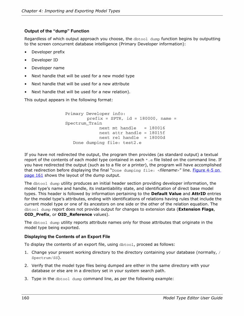
160 Model Type Editor User Guide
Chapter 4: Importing and Exporting Model Types
Output of the “dump” Function
Regardless of which output approach you choose, the dbtool dump function begins by outputting to the screen concurrent database intelligence (Primary Developer information):
• Developer prefix
• Developer ID
• Developer name
• Next handle that will be used for a new model type
• Next handle that will be used for a new attribute
• Next handle that will be used for a new relation).
This output appears in the following format:
If you have not redirected the output, the program then provides (as standard output) a textual report of the contents of each model type contained in each *.e file listed on the command line. If you have redirected the output (such as to a file or a printer), the program will have accomplished that redirection before displaying the final “Done dumping file: <filename>” line. Figure 4-5 on page 161 shows the layout of the dump output.
The dbtool dump utility produces an initial header section providing developer information, the model type’s name and handle, its instantiability state, and identification of direct base model types. This header is followed by information pertaining to the Default Value and AttrID entries for the model type’s attributes, ending with identifications of relations having rules that include the current model type or one of its ancestors on one side or the other of the relation equation. The dbtool dump report does not provide output for changes to extension data (Extension Flags, OID_Prefix, or OID_Reference values).
The dbtool dump utility reports attribute names only for those attributes that originate in the model type being exported.
Displaying the Contents of an Export File
To display the contents of an export file, using dbtool, proceed as follows:
1. Change your present working directory to the directory containing your database (normally, /Spectrum/SS).
2. Verify that the model type files being dumped are either in the same directory with your database or else are in a directory set in your system search path.
3. Type in the dbtool dump command line, as per the following example:
Primary Developer info:prefix = SPTR, id = 180000, name =
Spectrum_Train next mt handle = 180016 next attr handle = 18015f next rel handle = 18000d Done dumping file: test2.e

Using dbtool to Export or Import Model Types
Model Type Editor User Guide 161
../SS-Tools/dbtool dump src_file.e > dumpouts/file1234.txt
Given this command, the dbtool dump utility would read the src_file.e file and create an ASCII text file named file1234.txt in the /Spectrum/SS/dumpouts directory (which you must have previously created). You can then use amy preferred editor/viewer program to examine the contents of that file) or send it to a printer.
Figure 4-5: Information Provided in “dbtool dump” Output
Alternatively, you can use the command of the following example to make the dbtool dump_mt utility display the first screen of a temporary file containing the contents of both the arc_file.e and com_file.e catalog files, providing you with a viewable reference listing of those contents.
../SS-Tools/dbtool dump_mt src_file.e com_file.e | more
Developer Name = Spectrum_Train,Developer ID = 180000Mtype = JBS_Exerc4 Handle : 0x180016 Instantiable : TRUE Base_mts : 1. Name = NOT FOUND, Handle = 0x180005
Attributes:*Name = NO_NAME ID = 0x10000 DEFAULT VAL = JBS_Exerc4
... ... ...
*Name = NO_NAME ID = 0x11aed DEFAULT VAL = 1234
... ... ...
*Name = Multiplicator ID = 0x18015f DEFAULT VAL = 1234
... ... ...
*Name = NO_NAME ID = 0x10b77 DEFAULT VAL = 0
--------------------------------------------Relation Name = Closes ( 10048, 10042 )
Developer information (Developer name and Developer ID)
Inherited Attribute (Handle and Default Value, only)
Originated Attribute (Name also provided)
Model Type Name (Always included)
Instantiability (Always included to show state)
Name Entry (Not listed in Attribute View)
Model Type Handle (Always included)
Base Model Type (Not named unless included in export file)
Relations (listing only those which have rules that include this model or an ancestor on one side or the other).

162 Model Type Editor User Guide
Chapter 4: Importing and Exporting Model Types
Importing a MIBSPECTRUM manages devices on the basis of the requirements and values specified for each such device in its MIB (Management Information Base) document. A MIB essentially defines a database of paths and objects (locations) that store information concerning an SNMP device. Looked at in another way, a MIB is a collection of information that defines all of the objects that can be managed on the associated device, organizing this information in a tree structure, which begins at the root and has various branches that organize the managed objects in logical groups. The MIB presents its information in a special type of notation, called Abstract Syntax Notation One (ASN.1), which is very much like a programming language in many respects and generally seems incomprehensible unless you have developed familiarity with that notation system. [For more information on MIB definition and format, refer to RFC 1158, Structure and Identification of Management Information for TCP/IP-based Internets, which defines the SMI (Structure of Management Information) organization, presenting the rules for describing management information. Developments of MIB standards are coordinated by the Internet Engineering Task Force (IETF), a very large international community of network designers, vendors, researchers, and operators concerned with the evolution of Internet architecture.]
The MTE’s MIB-importing feature provides a convenient way to group and add attributes to the SpectroSERVER database. This is particularly useful when creating a model type to represent a non-Aprisma device for which no management module is provided. The imported MIB attributes are automatically grouped for the model type and added to the database.
The MTE supports the importation of both SNMPv1 and SNMPv2 MIBs (when importing an SNMPv2 MIB, the MTE maps that MIB’s data type to the corresponding data type defined in SNMPv1).
The MTE supports most of the standard textual conventions that can be used in a MIB. In addition, enumerations associated with these standard textual conventions are also supported.
Preparation
The MTE’s MIB import process handles all types of SNMP MIBs, but is subject to certain rules. If you want to use MIBs stored in RFC (Request For Comment) format, you must first remove the introductory, trailer, and any miscellaneous text comments, as follows:
1. Open an X-Window and make a copy of the MIB text file.
Example: cp rfc1516.txt rfc516.mib
2. Using vi or any preferred text editor of choice, strip off the introductory and closing text and then delete any interim page-identification text. Figure 4-6 on page 163 delineates the steps that must be made.

Importing a MIB
Model Type Editor User Guide 163
Figure 4-6: Procedure for Stripping Text-Type MIB file
Possible MIB Problems You May Need to Fix
The MTE’s MIB import process does not accept certain constructions, including some that are within allowed SMI limits. The following subsections identify specific problems and provide either a solution or a work-around:
1. Data Definition Language syntax errors, resulting from lack of adherence to ASN.1 conventions:
a. Modules must be unique to a Model Type, covering all entries up to and including the next END statement.
b. The first character of a module must be upper-case.
Example: SYNOPTICS-COMMON-MIB
c. The first character of an IETF Defined Data Type designation must be upper-case.
Example: Counter, Gauge, IpAddress
d. The first letter of a Managed Object entry must be lower-case, regardless of where it occurs in the grammatical structure.
Example: s3ChassisFanStatus
e. Macros must be all upper-case characters.
Example: OBJECT IDENTIFIER ::={mib28}
f. Only one comment string (test introduced by a pair of hyphens) can appear on a single line; nested comment strings are not supported.
vi rfc1516.mib
/BEGIN<Return>
<Ctrl>G
:1<Return>
[n]dd
/END<Return>
+
[n]dd
:1<Return>
/Page<Return>
–4dd
/<Return>
Open rfc1516.mib file.Move to line following introduction.Determine current line number.Return to top of file.Delete all introductory lines (where n = BEGIN line number minus one).a
Move to line marking end of MIB.Move to start of next-following line.Delete all closing lines (where n = convenient numbers), repeated until no closing text remains).Return to top of file.Move to first text line of page header. (Using MIB author’s name may be safer.)Move to start of preceding (blank) line.Delete the 4-line header text.Repeat header-search function.Repeat the last three steps as necessary to find and delete all subsequent page headers, leaving a pure MIB file.
a. IET-approved MIBs begin with the BEGIN line, but some proprietary MIBs include the identifier title and comment lines ahead of it, and these should be left in place.

164 Model Type Editor User Guide
Chapter 4: Importing and Exporting Model Types
g. Clauses used to describe Managed Objects must be all-upper-case characters. SYNTAX, ACCESS, and STATUS clauses are required; DESCRIPTION, REFERENCE, INDEX, and DEFVAL clauses are optional.
2. Tables (defining groupings of objects, where each object group is called a row and rows consist of columns), have their own special conventions of order and syntax, as follows:
a. A table description must begin with a lower-case character and end with a “Table” textstring.
Example: s3CommonBoardTable
b. A Table Description syntax clause must begin with a: “SYNTAX SEQUENCE OF <Sequence Name>” textstring.
Example: SYNTAX SEQUENCE OF S3CommonBoardEntry
c. A Sequence Name component must begin with an upper-case letter and end with an “Entry” textstring.
Example: S3CommonBoardEntry ::= SEQUENCE{
d. A row entry must begin with a lower-case letter and end with an “Entry” textstring.
Example: s3CommonBoardEntry
e. A row entry must have a SYNTAX clause that contains the name of the <Sequence Name> component, which defines the columns in the table.
Example: SYNTAX S3CommonBoardEntry
3. The MTE’s MIB import process does not accept IMPORTS statements.
Example: The MIB RFCs allow the following statement:
IMPORTS $3000enetBoard from the SYNOPTICS-ROOT-MIB.
To resolve this situation, simply replace the IMPORTS statement with an actual definition, as follows:
$3000enetBoard ::={s300Ethernet 2}
4. The MTE’s MIB import process for earlier versions than SPECTRUM Release 6.0.0 does not accept enumerated integers having a value of 0 (zero).
Example: An otherwise acceptable MIB might contain the following definition:
To resolve this situation, search the MIB for “(0)” and change any such instances that are part of an enumerated integer to some large positive integer, such as 9999 — and add a comment stating that they were changed from 0 to allow the MIB to compile.
s3ChassisFanStatus OBJECT-TYPESYNTAX INTEGER{
ok(0)Fail(2)Fail(3)}
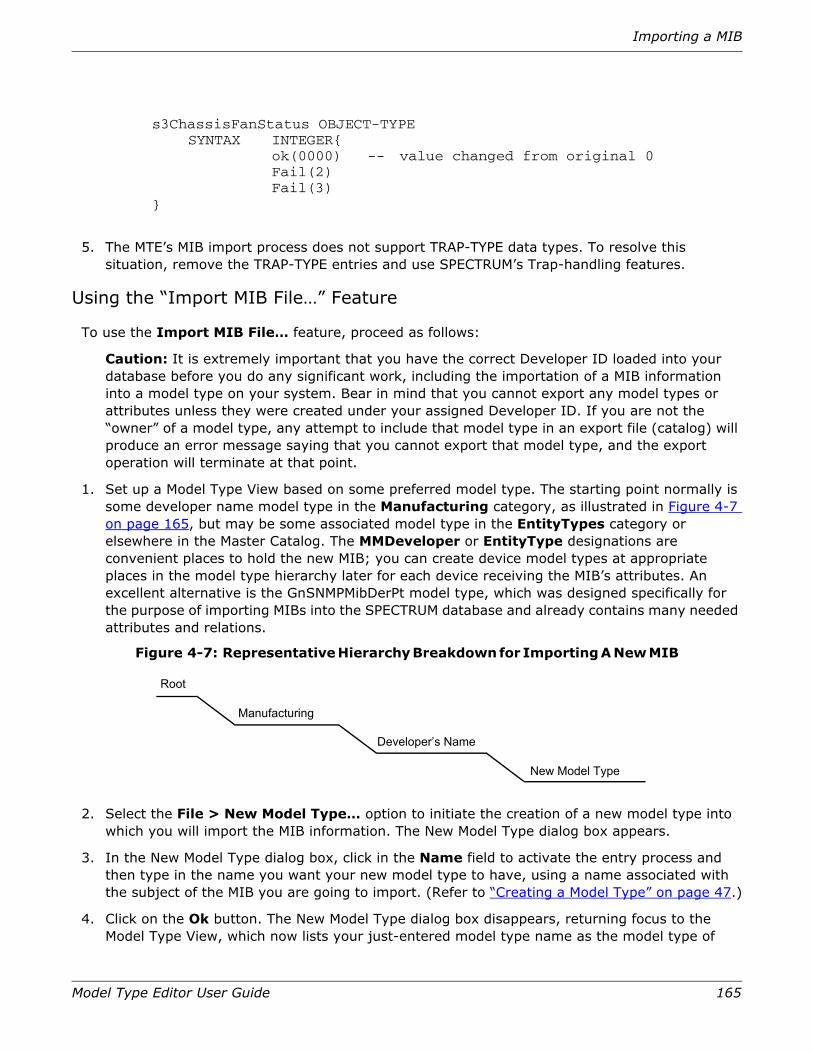
Importing a MIB
Model Type Editor User Guide 165
5. The MTE’s MIB import process does not support TRAP-TYPE data types. To resolve this situation, remove the TRAP-TYPE entries and use SPECTRUM’s Trap-handling features.
Using the “Import MIB File…” Feature
To use the Import MIB File… feature, proceed as follows:
Caution: It is extremely important that you have the correct Developer ID loaded into your database before you do any significant work, including the importation of a MIB information into a model type on your system. Bear in mind that you cannot export any model types or attributes unless they were created under your assigned Developer ID. If you are not the “owner” of a model type, any attempt to include that model type in an export file (catalog) will produce an error message saying that you cannot export that model type, and the export operation will terminate at that point.
1. Set up a Model Type View based on some preferred model type. The starting point normally is some developer name model type in the Manufacturing category, as illustrated in Figure 4-7 on page 165, but may be some associated model type in the EntityTypes category or elsewhere in the Master Catalog. The MMDeveloper or EntityType designations are convenient places to hold the new MIB; you can create device model types at appropriate places in the model type hierarchy later for each device receiving the MIB’s attributes. An excellent alternative is the GnSNMPMibDerPt model type, which was designed specifically for the purpose of importing MIBs into the SPECTRUM database and already contains many needed attributes and relations.
Figure 4-7: Representative Hierarchy Breakdown for Importing A New MIB
2. Select the File > New Model Type… option to initiate the creation of a new model type into which you will import the MIB information. The New Model Type dialog box appears.
3. In the New Model Type dialog box, click in the Name field to activate the entry process and then type in the name you want your new model type to have, using a name associated with the subject of the MIB you are going to import. (Refer to “Creating a Model Type” on page 47.)
4. Click on the Ok button. The New Model Type dialog box disappears, returning focus to the Model Type View, which now lists your just-entered model type name as the model type of
s3ChassisFanStatus OBJECT-TYPESYNTAX INTEGER{
ok(0000) -- value changed from original 0Fail(2)Fail(3)
}
Root
Manufacturing
Developer’s Name
New Model Type

166 Model Type Editor User Guide
Chapter 4: Importing and Exporting Model Types
interest in its Model Type Name field, with the previously selected “starting point” model type now listed in the Base Model Type field.
5. At the Model Type View for the new model type, select the Import MIB option from the File menu. The Import MIB dialog box will appear.
6. Determine the path and filename for the MIB being imported, and then either edit the Selection field entry as applicable to specify the MIB location or else change the target focus of the Directory and Files selection fields as applicable to select the correct path and filename.
7. Determine the SMI (Structure of Management Information) path for the MIB being imported (as explicitly identified in the MIB text file). If that SMI path is not under the SMI Path field default entry for the Internet private-enterprise subtree, click in that field and change the entry as necessary to identify the correct SMI path.
8. Click on the OK button to confirm your selections. This action initiates the importing process.
If the MIB you are importing into your model type is compliant with all requirements, you will receive confirmation that the process was successful, as shown in Figure 4-8 on page 166.
Figure 4-8: Message Display When MIB Importation Process Succeeds
Note: If you are not the owner of the model type, a pop-up message will appear, warning that you will not be able to export this model type and attributes later. You will have the option of continuing or cancelling the importing of the MIB into the model type. Unless you are simply prototyping a model type, you should cancel out of the process and load the correct Developer ID and then reinitiate the process.
Errors and Warnings
If the MTE encounters a problem when importing the MIB, you will receive error and/or warning messages detailing the issues encountered.
Warnings
Warnings indicate that problems were encountered during the import process, but that the import was completed. All of the warnings encountered are displayed in a message box, once the import process has finished.
Success
The MIB was successfully imported
Close

Importing a MIB
Model Type Editor User Guide 167
Figure 4-9: Warning List
A typical warning encountered is the one caused by overly long attribute names. The MTE truncates attribute names containing more than 128 characters. For example, in the warning list shown above, the MIB attribute name ascUserNameForLastAttemptedLogin is truncated to ascUserNameForLastAttemptedLog when imported into the model type. In some cases, truncation of attribute names can cause an attribute name to become non-unique. When this occurs, an additional warning message is generated.
Clicking the Close button on the Warning List box displays the Success ? message box. This message explains that to save the import of the MIB despite the warning messages, you must use the Save command in the File menu of the MTE. To go back and edit the MIB syntax to eliminate the warning messages, close the MTE without saving.
Figure 4-10: The Success ? Message Box
Error Messages
If the MTE encounters an error that makes it unable to process the MIB import, the Errors and Warnings message box is shown indicating the error that was encountered. Once such an error is encountered, the MIB import is discontinued.

168 Model Type Editor User Guide
Chapter 4: Importing and Exporting Model Types
Figure 4-11: Error & Warning List Box
Clicking the Close button in the Errors and Warnings message box brings up a confirmation that the import process was not successful and that no attributes were created. You must go back to the MIB, eliminate the errors found, and try the import again.
Figure 4-12: Message Display When MIB Importation Process Fails
169
Chapter 5: The MTE Reports Utility
This chapter describes how to run the MTE Reports Utility and select the information you want to extract. This utility gathers model type and relation information from the database and produces a formatted report on your workstation’s standard output device.
ReportsThe MTE reports utility is in your SS-Tools directory, identified as reports on Solaris systems or as reports.exe on nt/Windows systems.
The reports utility is run at the command level. The steps involved in running a report are as follows:
1. Change to the directory which contains the SPECTRUM database/catalog (that is, make it the working directory).
2. Enter the appropriate command line to call the desired reports function from its resident directory. (Unless you have set up your system PATH statement so as to make it accessible from any other location, you must use a relative pathname to call the utility from its actual location.)
You can run only one report function at a time. In addition, the database is locked during a report generation sequence, so that other programs or utilities cannot use the database. This means that you cannot run a report on a database that is being concurrently accessed by a VNM, the MTE, or dbtool.
Caution: You cannot access a database/catalog that is currently being used by SpectroSERVER, another MTE, or another Aprisma application; safeguards built into the programs bar you from entering and display a message reporting what program/system currently has access to the data. Third-party utilities not produced by Aprisma might not provide such safeguards, however, and you must ensure that no such applications are running before running reports. Corruption of the database can occur if you do not comply with this restriction.
There are three basic command formats available:
• Command-line help
• Model Type Attribute Report

170 Model Type Editor User Guide
Chapter 5: The MTE Reports Utility
• Relations Report
Command Line HelpTo display the reports utility help message, use either of the following command syntax:
../SS-Tools/reports -help
or simply:
../SS-Tools/reports
Figure 5-1 on page 171 shows the list of command line syntax options which the reports help command displays on your screen.
Running a Relations ReportYou can run relation reports only on one relation at a time. The report output goes to the standard output device, which is normally your screen. Alternatively, you can redirect the output to a file, printer, or other output device (refer to “Directing Reports to an Output Device” on page 176). The output lists how one model type relates to another, according to the selected relation. To run a relation report, use the following syntax (refer to Figure 5-1 on page 171):
../SS-Tools/reports [-rel <relation>]
where:
-rel identifies the following argument, and <relation> is the name of the relation for which you wish to obtain a report.

Running a Relations Report
Model Type Editor User Guide 171
Figure 5-1: Command Line Help
Example: ../SS-Tools/reports -rel Connects_to
The above command would generate a report on the Connects_to relation, with the output going to the standard output device for the workstation. The report output would list each sequential rule in the Connects_to relation.
Figure 5-2 on page 172 is a representative output illustrating the report resulting from the request shown in the preceding paragraph. The report starts with some general information on the relation— identifying the full name (including the developer code), the unique handle, and the relation type, plus special “Help” functions, if any. The program then follows this heading information with the complete listing of the relation’s rules. The lines for the rules show the model type on the left as the “left” side of the relation and the model type on the right as the “right” side of the relation, much as you would see the same entries on the MTE’s Relation View (see Figure 2-48 on page 95). A representative rule format is: “SNMP_Device Connects_to Physical_Addr.”
reports [ [ -r ] -mtype <name_pattern> ][ -rel <name_pattern> ][ -handle <handle_pattern> ][ -attrflags bdefgklmprstw ]
'd' -- Database'e' -- External'f' -- Global'g' -- Guaranteed'l' -- Logged'm' -- Memory'p' -- Polled'r' -- Readable's' -- Shared'w' -- Writable
[ -fields bcdefghilmnostvwzGLP ]'b' -- Length in bytes'c' -- Creator model type'd' -- OID Reference'e' -- No attribute info printed'f' -- Flags'g' -- Polling Group'h' -- Help'i' -- Attribute ID'l' -- Lower limit'm' -- Manifest Constant Name'n' -- Name'o' -- OID Prefix's' -- Scale type't' -- Type'v' -- Default value'z' -- UNITS'G' -- Group ID'L' -- Logging Internal'P' -- Polling Internal
[ -help ][ -invisible ]

172 Model Type Editor User Guide
Chapter 5: The MTE Reports Utility
Figure 5-2: Sample Relations Report
Running a Model Type Attributes ReportYou can run model type attribute reports to retrieve attribute information for a particular model type. The report output goes to the standard output device, which is normally your screen. Alternatively, you can redirect the output to a file, printer or other output device (refer to “Directing Reports to an Output Device” on page 176). To run a model type report, use the following syntax:
../SS-Tools/ \reports [-mtype <model type>][-attrflags w][-fields][-invisible]
or
../SS-Tools/ \reports [-handle <model handle>][-attrflags ““][-fields][-invisible]
where:
-mtype
Identifies the character string of the argument that follows it (that is, the <model type> entry) as the search pattern specification of which model type(s) to report on. Given this command, the
Rel = Connects_toDefine Name:CS_CONNECTS_TOHandle: 10005Type: Many-to-manyRules:1. CM FddiMACCS Device2. CM FddiMACCS Physical_Addr3. CM FddiMACCS VNM4. CM FddiNoMACCS Device
… 13. CS Bdg_CSI_CGenCS Hub14. CS Bdg_CSI_CGenCS Hub_CSI_CIRM15. CS Bdg_CSI_CGenCS Hub_CSI_IRBM
… 32. CS BridgeCS Device33. CS Carrier_SegmntCS Device34. CS Coax_SegmentCS Device35. CS Coax_SegmentCS Physical_Addr36. CS DeviceCS FDDI37. CS DeviceCS LAN_802_3
… 65. CS PingableCS Pingable66. CS PingableCS SNMP_Device67. CS PingableCS WA_Segment
… 107. CSSW ATM_NetworkCSSW Switch108. CSSW ATM_NetworkCSSW Switching
… 135. SNMP GnSNMPDevCS RBdg_Rx_4820S136. SNMP GnSNMPDevCSSW SwitchClient

Running a Model Type Attributes Report
Model Type Editor User Guide 173
reports utility would report on all model types containing the <model type> text string. If the model type identified by the <model type> were IRM, for example, the report would list sections for Hub_CSI_CIRM, Hub_CSI_IRM2, Hub_CSI_SIRM, and all other model types that contained the “IRM” character string in their model type names.
-handle
Identifies the character string of the argument that follows it (that is, the <model handle> entry), with or without a preceding “0x” prefix) as the search pattern specification of which model type(s) to report on. This command does the same thing as the -mtype command, except that it accepts a model type handle rather than a name string. If the <handle> entry were 0x180027, for example, the report would list sections for the 27th model type created under the 0x180000 Developer ID. If the given handle entry were 180, conversely, the report would cover not only all model types created under that Developer ID but also any other model types that happened to have those same three digits anywhere in their handles.
-attrflags
Identifies the character string that follows it as a collection of code values the program should use as a filter to select among the attributes for the chosen model type(s). You should list all attribute flags to be used in the filter. If you use a pair of quotes (single or double) with no intervening character as the argument after this -attrflags command (as is the case in the second example shown above), the program shows all fields. If you do not include an argument, the program regards this as an error condition and shows the help file. Figure 5-1 on page 173 shows the coding for the attribute flag.
a. Entering two consecutive single-quote or double-quote characters instead of an acceptable argument is equivalent to entering all arguments at once. (Entering the -attrflags command with no following argument will produce an error condition, however, and the reports utility will display its help file as a guideline.)
Table 5-1: Coding for -attrflags Entries in Reports
[-attrflags bdefgklmprstw]
d Database
e External
f Global
g Guaranteed
l Logged
m Memory
p Polled
r Readable
s Shared
w Writable
“<no flags defined>”a all

174 Model Type Editor User Guide
Chapter 5: The MTE Reports Utility
-fields
Establishes what information is to be provided in the report. Figure 5-2 on page 174 lists the available fields and their functions. You should list all fields to be used in the filter. If no -fields are listed, all fields are displayed.
a. Entering two consecutive single-quote or double-quote characters instead of an acceptable argument is equivalent to entering all arguments at once, producing a full report. (Entering a -fields command with no following argument will produce an error condition, however, and the reports utility will display its help file as a guideline.)
Note: The Modeltype_Name and Modeltype_Handle attributes are not visible in the MTE’s Attribute View scroll list window, but are included in the reports outputs.
Table 5-2: Coding for -fields Entries in Reports
[-fields becfghilmnorstvwzGLP]
b Length in bytes
c Creator model type
d OID Reference
e No attribute info printed
f Flags
g Polling Group
h Help
i Attribute ID
l Lower limit
m Manifest Constant Name
n Name with developer ID
o OID Prefix
r Read user level
s Scale type
t Type
v Default Value
w Write user level
z UNITS
g Group ID
L Logging Internal
P Polling Internal
“<no fields defined>”a all

Running a Model Type Attributes Report
Model Type Editor User Guide 175
-invisible
This option directs the reports utility to include all invisible model types created under the currently loaded Developer ID that match the search pattern, as well as all visible model types that match the search pattern.
Example: reports -mtype HUB_CSI_IRM2 -attrflags e -fields don -invisible
This example generates a report on the HUB_CSI_IRM2 model type, listing all attributes with the External flag set. The -fields entry calls for the output to provide the OID Reference, OID Prefix, and Name (with Developer ID) identifications for each attribute that gets reported. Figure 5-3 represents the header portion of the report that might be obtained from this report request. Figure 5-4 on page 176 illustrates what the body of the report will look like.
Figure 5-3: Example of Header Section of Report Output
This initial heading-type output then will be followed by a full list of Base Model Types in order of inheritance, presented in the following format:
Mtype = CSHub_CSI_IRM2Define Name :CS_Hub_CSI_IRM2Handle : 10059Instantiable:TRUEVisible: FALSEDerivable:FALSENo Destroy:FALSEUnique : FALSE OID REFRequired: FALSEBase_mts:
1 CSI_MMAC2. CSI_Hub_Frag23. CSI_Hubs
…

176 Model Type Editor User Guide
Chapter 5: The MTE Reports Utility
Figure 5-4: Representative Body of Report, Listing Base Model Types in Order of Inheritance
Directing Reports to an Output DeviceThe Reports utility sends its output to the workstation’s standard output device, which normally is your display screen. If you wish to redirect the output to a file or printer directly, you need to provide standard UNIX piping commands in the command line to redirect the report output as desired.
Attributes: Name = CS ADiscClassFrag ADiscClassFrag Define Name = CS_ADISCCLASSFRAG_ADISCCLASSFRAG ID = 0x11aed Attr group ID = 0x11bb9 CREATED BY = CS ADiscClassFrag TYPE = Group ID SIZE IN BYTES = 4 FLAGS = READABLE SHARED XFLAGS = DATABASE POLLING GROUP = 0 HELP = OID PRE = OID REF = SCALE TYPE = None UNITS = POLLING INTERVAL = 0LOGGING INTERVAL = 0 DEFAULT VAL = 0
Name = CS ADiscClassFrag ConnectionPrec Define Name = CS_ADISCCLASSFRAG_CONNECTIONPREC ID = 0x11a3e Attr group ID = 0x11aed CREATED BY = CS ADiscClassFrag TYPE = Integer SIZE IN BYTES = 4 FLAGS = READABLE WRITABLE XFLAGS = MEMORY DATABASE POLLING GROUP = 0HELP = OID PRE = OID REF = SCALE TYPE = None UNITS = POLLING INTERVAL = 0LOGGING INTERVAL = 0 DEFAULT VAL = 0
…
(Followed by additional attributes and their descriptions, as applicable.)

Directing Reports to an Output Device
Model Type Editor User Guide 177
Example 1:
reports -mtype HUB_CSI_IRBM -attrflags e -fields n
The above command line would generate an output report on the HUB_CSI_IRBM model type. The report would begin with a standard header section that identifies the model type’s developer, its name and handle, the state of the six attribute flags, and the identity of direct base model types. The remainder of the report would be restricted to External-flagged attributes, and the line items in the report would list only the attribute names. This report would appear on your workstation screen as a one-time only display (and, if too long, you would only be able to see the end of the report, meaning however many lines of text your particular display is capable of showing).
Example 2:
reports -mtype HUB_CSI_IRBM -attrflags e -fields n | more
The above command line would generate exactly the same report as the preceding example, but the report would be sent to your workstation screen as an incremental display file, showing you the first screen. To increment through successive lines while viewing the screen, you would press Return; to increment to the next following screen, you would press the spacebar.
Example 3:
reports -mtype HUB_CSI_IRBM -attrflags e -fields n > REPORT_1
The above command line would generate exactly the same report as the preceding examples, but the program would output the report as an ASCII file named REPORT_1 in your current directory. If you wished, you could precede the filename with a pathname to have the file generated in some predefined directory elsewhere in your system. If the named file already exists at the applicable destination, the new report will overwrite it.
Example 4:
reports -mtype HUB_CSI_IRBM -attrflags e -fields n > lpr -P<ptr>
The above command line would generate exactly the same report as the preceding examples, but the program would send it as a print file to the printer designated by <ptr>.
Note: For both the -mtypes and -rel commands, you can substitute a period (.) as a wildcard for “all applicable” entries. A “reports -mtype .” command would run reports on all model types, for example, whereas a “reports -rel .” command would run reports on all relations.

178 Model Type Editor User Guide
Chapter 5: The MTE Reports Utility

179
Chapter 6: MTE Resources
This chapter lists unique resources used to configure basic features of the MTE. The representation of the Spectrum/app-defaults/mte file at the beginning of this appendix shows the default values initially supplied with SPECTRUM 5.0. The following text then explains how these can be modified to satisfy individual user preferences or needs. For more information on how to edit resources, refer to “Redefining MTE Resources” on page 179.
Default MTE Resource File
The basic appearance (colors, default font and font sizes, pointer style, etc.) of the MTE windows is controlled by the Motif window manager (Mwm). You can copy these parameters from the Spectrum/app-defaults/mte file into the ~/.Xdefaults file and make localized changes applicable for your use. If a particular resource is mentioned in both the Spectrum/app-defaults/mte file and in the ~/.Xdefaults file, the ~/.Xdefaults file value takes precedence. Refer to the Motif Window Manager User’s Guide for information on specific resources and the values that define them.
Figure 6-1 on page 180 is a representation of the default MTE resources, defining the default setup, along with the text of error messages, as it appears in the Spectrum/app-defaults/mte file after you install SPECTRUM 5.0. All of these elements are subject to operator modification, as described in the next section, in accordance with personal choice or needs.
Redefining MTE Resources
You can use vi or any preferred shell editor to customize the following MTE resources for your system
Fonts
Fonts used in the MTE utility are defined in accordance with ISO8859-1 specifications, which provide for 14 different variables identifying the foundry type, typeface family, weight, slant, etc. Fonts can be selected from any one of three different X Window System font subdirectories for use in the MTE.

180 Model Type Editor User Guide
Chapter 6: MTE Resources
To determine the correct coding for an alternative font, you can use the xfontsel utility to examine the available fonts in your system and then copy the resulting code specification into whichever resources file you prefer in place of the default coding. If you enter a code for a font that is not available in your system, the Spectrum/app-defaults/spectrum.fonts aliasing file will substitute the nearest-equivalent font it can find. For information on the X Window System font directories, refer to Defining Resources.
Figure 6-1: Contents of the Spectrum/app-defaults/mte File
The resource files specify colors you can use in the MTE. The color designations are located in different files on different machines and may vary in hue on different monitors, as well. To determine what colors are available in your machine, run the showrgb program, which identifies the accepted name designation on your machine for each listed color and also provides a breakdown of the red-green-blue components of each color. You can use these number values to set up the different colors on any of a variety of commonly available color-projection programs to help you select which colors you want to specify in your resource file. Refer to your X Window System documentation for a description of RGB notation and associated color names.
Resource File Commands
The functions of the different commands in the resource file are as follows:
Warnings
The mte*warnings_enabled command specifies whether warning messages are set TRUE (on) or FALSE (off). The default setting is TRUE, meaning that warnings and error messages will be displayed as applicable during MTE operation. You can toggle this command switch off or on by activating the File > Toggle Warnings option in the Model Type View. If this command is set to FALSE, moreover, the MTE not only will bypass the warning messages but also will operate with a pre-Release 4.0 functionality with respect to the right mouse button—that is, clicking on the right
## Model Type Editor resources## mte resourcesmte*warnings_enabled: TRUEmte*background: grey50mte*foreground: yellowmte*topShadowColor: whitemte*bottomShadowColor: midnight bluemte*menufont: -*-courier-bold-o-*-*-17-120-*-*-*-*-*-*mte*labelfont: -*-courier-bold-o-*-*-17-120-*-*-*-*-*-*mte*listfont: -*-courier-bold-o-*-*-17-120-*-*-*-*-*-*mte*textfont: -*-courier-bold-o-*-*-17-120-*-*-*-*-*-*mte*msgfont: -*-courier-bold-r-*-*-17-120-*-*-*-*-*-*mte*buttonfont: -*-courier-bold-r-*-*-17-120-*-*-*-*-*-*
! Note: the following resource colors menu bars consistently on VUEmte*useColorObj: false
mte*geometry: 650x350+300+100mte*groupcolor: blackmte*inviscolor: red

Redefining MTE Resources
Model Type Editor User Guide 181
button will close the current view without saving any in-process changes that you might have already established.
Syntax:
mte*warnings_enabled: TRUE
where:
TRUE is the preferred setting, ensuring that MTE operators are informed of problems and incompatibilities determined by the program during operation.
Background Color
The mte*background command specifies the panel-face color to be used for the panel face in the MTE windows.
Syntax:
mte*background: grey50
where:
grey50 is the default background color for all views and dialog boxes. You can specify any color by showrgb-designated name or by using hexadecimal RGB notation (for example, 000 for black, 600 for a dark red, or 0AA for a medium green-blue).
Foreground Color
The mte*foreground command specifies the foreground color to be used for normal text characters throughout the MTE window set (labels, text, lists, data entries, etc.).
Syntax:
mte*foreground: yellow
where:
yellow is the color for all normal text. You can specify any color by showrgb-designated name or by using hexadecimal RGB notation (for example, 000 for black, 600 for a dark red, or 0AA for a medium green-blue).
Top Shadow Color
The mte*topShadowColor command specifies the color to be used for object lines representing an oblique surface reflecting direct light from a source above and to the left of the window. The selected color is applied to lines representing the upper and left edges of an object that protrudes out from the surrounding surface, toward the viewer (such as a push-button), or else the bottom and right edges of an object recessed into that surrounding surface, away from the viewer (such as a cavity).
Syntax:
mte*topShadowColor: white
where:

182 Model Type Editor User Guide
Chapter 6: MTE Resources
white is the color for the reflecting surface receiving direct light. You can specify any color by showrgb-designated name or by using hexadecimal RGB notation (for example, 000 for black, 600 for a dark red, or 0AA for a medium green-blue).
Bottom Shadow Color
The mte*bottomShadowColor command specifies the color for object lines representing an oblique surface shadowed by an overhanging surface from direct light projected as coming from a source above and to the left of the window. The selected color is applied to lines representing the lower and right edges of an object that protrudes out from the surrounding surface, toward the viewer (such as a push-button), or else the top and left edges of an object recessed into that surrounding surface, away from the viewer (such as a cavity).
Syntax:
mte*bottomShadowColor: midnight blue
where:
midnight blue is the color for the hidden surface shadowed from direct light. You can specify any color by showrgb-designated name or by using hexadecimal RGB notation (for example, 000 for black, 600 for a dark red, or 0AA for a medium green-blue).
Menu Font
The mte*menufont command specifies the font for the menu-bar labels and for option description text in pull-down menus in the MTE views.
Syntax:
mte*labelfont:-*-courier-bold-o-*-*-17-120-*-*-*-*-*-*
where:
-*-courier-bold-o-*-*-17-120-*-*-*-*-*-* is the default ISO8859 font code, specifying a Courier Bold Oblique “pica” font.
Label Font
The mte*labelfont command specifies the font for panel-nomenclature labels in the MTE views and dialog boxes.
Syntax:
mte*labelfont:-*-courier-bold-o-*-*-17-120-*-*-*-*-*-*
where:
-*-courier-bold-o-*-*-17-120-*-*-*-*-*-* is the default ISO8859 font code, specifying a Courier Bold Oblique “pica” font.
List Font
The mte*listfont command specifies the font for list entries in the MTE views and dialog boxes (that is, lists of attributes, relations, rules, etc. in list scroll fields).
Syntax:
mte*labelfont:-*-courier-bold-o-*-*-17-120-*-*-*-*-*-*

Redefining MTE Resources
Model Type Editor User Guide 183
where:
-*-courier-bold-o-*-*-17-120-*-*-*-*-*-* is the default ISO8859 font code, specifying a Courier Bold Oblique “pica” font.
Text Font
The mte*textfont command specifies the font for text entries in the MTE views and dialog boxes (that is, those entries which are or can be typed in by the user as filter character strings, etc.).
Syntax:
mte*labelfont:-*-courier-bold-o-*-*-17-120-*-*-*-*-*-*
where:
-*-courier-bold-o-*-*-17-120-*-*-*-*-*-* is the default ISO8859 font code, specifying a Courier Bold Oblique “pica” font.
Msg Font
The mte*msgfont command specifies the font for message entries in the dialog boxes (that is, those reminders and error messages that pop up when the user needs to be advised about the need for a decision or has called for some action that is not in compliance with program specifications).
Syntax:
mte*labelfont:-*-courier-bold-r-*-*-17-120-*-*-*-*-*-*
where:
-*-courier-bold-r-*-*-17-120-*-*-*-*-*-* is the default ISO8859 font code, specifying a Courier Bold Regular “pica” font.
Button Font
The mte*buttonfont command specifies the font for nomenclature labels on buttons in the MTE views and dialog boxes.
Syntax:
mte*labelfont:-*-courier-bold-r-*-*-17-120-*-*-*-*-*-*
where:
-*-courier-bold-r-*-*-17-120-*-*-*-*-*-* is the default iso8859 font code, specifying a Courier Bold Regular “pica” font.
Object Color Correction
The mte*useColorObj parameter is included in the mte resource file to resolve a peculiarity in the Hewlett-Packard operating system (not currently supported). This variable had to be set to True for operation on Hewlett-Packard platforms, but should be left False for Sun/Solaris, NT, or other platforms.

184 Model Type Editor User Guide
Chapter 6: MTE Resources
Syntax:
mte*useColorObj: False
where:
False is the default setting for operation on Sun/Solaris, NT, etc.
Geometry
The mte*geometry parameter defines the size and initial position of the Model Type View when the MTE program is turned on.
Syntax:
mte*geometry: 650x350+300+100
where:
650x350+300+100 is the default setting.
Group Color
The mte*groupcolor parameter defines the color for names of group attributes when they appear in a list of attributes in the Attribute View and in the Attribute Group List dialog box.
Syntax:
mte*groupcolor: black
where:
black is the default color for group attributes. You can specify any color by name or by using hexadecimal RGB notation (for example, 000 for black, 600 for a dark red, or 0AA for a medium green-blue).
Invisible Color
The mte*invisicolor parameter defines the color used to present model type names for model types that have been flagged as not visible.
Syntax: mte*inviscolor: red
where:
red is the default color for invisible model types. You can specify any color by name or by using hexadecimal RGB notation (for example, 000 for black, 600 for a dark red, or 0AA for a medium green-blue).
Error Messages
Figure 6-2 on page 185 delineates the error message text provided in the mte resource file, with each entry triggered by conditions identified by the introductory label. Users can modify these messages as applicable for international or specialized use.
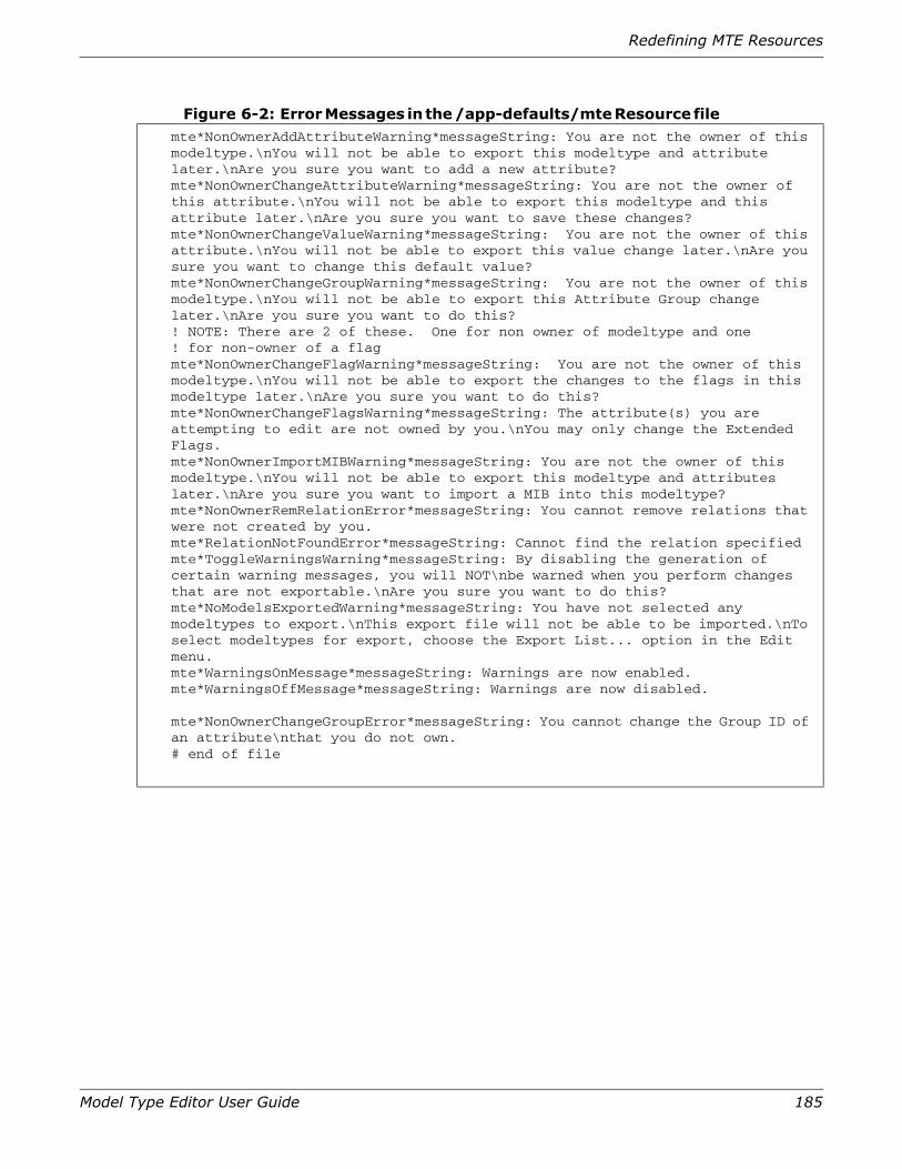
Redefining MTE Resources
Model Type Editor User Guide 185
Figure 6-2: Error Messages in the /app-defaults/mte Resource file mte*NonOwnerAddAttributeWarning*messageString: You are not the owner of this modeltype.\nYou will not be able to export this modeltype and attribute later.\nAre you sure you want to add a new attribute?mte*NonOwnerChangeAttributeWarning*messageString: You are not the owner of this attribute.\nYou will not be able to export this modeltype and this attribute later.\nAre you sure you want to save these changes?mte*NonOwnerChangeValueWarning*messageString: You are not the owner of this attribute.\nYou will not be able to export this value change later.\nAre you sure you want to change this default value?mte*NonOwnerChangeGroupWarning*messageString: You are not the owner of this modeltype.\nYou will not be able to export this Attribute Group change later.\nAre you sure you want to do this?! NOTE: There are 2 of these. One for non owner of modeltype and one! for non-owner of a flagmte*NonOwnerChangeFlagWarning*messageString: You are not the owner of this modeltype.\nYou will not be able to export the changes to the flags in this modeltype later.\nAre you sure you want to do this?mte*NonOwnerChangeFlagsWarning*messageString: The attribute(s) you are attempting to edit are not owned by you.\nYou may only change the Extended Flags. mte*NonOwnerImportMIBWarning*messageString: You are not the owner of this modeltype.\nYou will not be able to export this modeltype and attributes later.\nAre you sure you want to import a MIB into this modeltype?mte*NonOwnerRemRelationError*messageString: You cannot remove relations that were not created by you.mte*RelationNotFoundError*messageString: Cannot find the relation specifiedmte*ToggleWarningsWarning*messageString: By disabling the generation of certain warning messages, you will NOT\nbe warned when you perform changes that are not exportable.\nAre you sure you want to do this?mte*NoModelsExportedWarning*messageString: You have not selected any modeltypes to export.\nThis export file will not be able to be imported.\nTo select modeltypes for export, choose the Export List... option in the Edit menu.mte*WarningsOnMessage*messageString: Warnings are now enabled.mte*WarningsOffMessage*messageString: Warnings are now disabled.
mte*NonOwnerChangeGroupError*messageString: You cannot change the Group ID of an attribute\nthat you do not own.# end of file

186 Model Type Editor User Guide
Chapter 6: MTE Resources

187
Index
Symbols.e file 143, 146, 154.m file (example) 157.v file 155.VNMDB.LOCK file 12, 144
Aaccelerators 33Add Base Model Type… function 112Add to (attribute groups) button 90adding attributes to the SpectroSERVER
database 162adding Developer ID to database 11adding vendor information 11Alter Flags… option 79Alter Group… option 76Alter Value dialog box
altering single value 76Alter Value… option 76, 120altering
attribute flags 82attribute group assignment 76
attribute 12adding to a model type 56adding to the SpectroSERVER database 162altering characteristics of 75assigning to group 86creating an Attribute Group 83editing 71editing definition of 73editing guidelines 72extension fields
OID Prefix 131extension flags
Database 132Keyed Attributes 133Logged 132Memory 132Polled 132Polling Group 130
filterapplying 65clearing 67
flagsExternal 128Global 130Guaranteed 130Preserve Value 130Readable 128Shared 130Writable 129
group 83 to 92adding to 90altering 81altering assignment 76changing name of 92clearing 89collapsing 88creating 83, 89deleting 91exploding 87managing 83 to 92
removing from a model type 58Attribute Description controls 57
Group ID control 126List button 125Type selector 123
Attribute Description FieldsGroup ID
Collapse/Collapse All 88Explode/Explode All 87
188 Model Type Editor User Guide
Index
Name 123Type 124, 125
Attribute Edit View 105, 121description fields 122 to 128description flags 128 to 130edit menu 134extension fields 130 to 131extension flags 132file menu 134menu bar 133
Edit menu options 134File menu options 134
Attribute Extended Description controls 57Attribute Group List dialog box 83 to 92
(illustrated) 85Attribute View 105, 112 to 121
Edit menu options 120 to 121fields 113
Attribute Group 117Attribute ID 117Attribute Names 116Derivable flag 115For Model Type 113Instantiable flag 114No Destroy flag 115Required flag 116Unique flag 115Values 116Visible flag 114
menu bar 118Edit menu options 120 to 121View menu options 121
menu selections 118 to 121View menu options 121
Bbackground color 181background resource command 181backing up your database 144base model type 144bottom shadow color 182bottomShadowColor resource command 182button font 183buttonfont resource command 183
Ccatalog 143
importing into database 145Change Group Name dialog box 92
(illustrated) 93
Change/Desc button 92Clear (Clr) Filter… function 110Clear Groups button 89Collapse (attribute groups) button 88Collapse All (attribute groups) button 89color
background 181bottom shadow 182foreground 181groups 184invisible 184top shadow 181
command line syntax for different dbtool applications 153
constraintsexporting with MTE 146
conventions used in this book 6converting MIB text file manually 162Copy function 111, 120, 134, 139Create (attribute groups) button 89creating
attribute group 83customization (resource file) 179
Ddatabase
access 12adding attributes to 162need for backup 145precautions 24protection 24
Database attribute extension flag 132dbpart parameter
with dbtool 155dbtool
commands 156dbpart parameter 155dependencies 152dump parameter 154dump_mt parameter 154export parameter 155, 156extract files 152file types 152import parameter 155model type list files 152use of 151 to 161
Delete (attribute groups) button 91dependencies 144
with dbtool 152Derivable flag 115derivation links 144derivations 12

Model Type Editor User Guide 189
derived model type 16, 17Derived Model Types field 107description fields (Attribute Edit
View) 122 to 128destroying a model type 54developer ID 15, 17, 49, 58, 67, 69, 72, 75, 77, 79,
90, 92, 97, 98, 99, 100, 102, 107, 110, 112, 114, 117, 120, 121, 123, 128, 130, 132, 135, 139, 144, 147, 148, 152, 153, 157, 160, 165, 166, 173, 175
dialog box 39cut list 46Find Attribute 61find model type 39, 68Set Attribute Filter 64Set Model Type Filter 42
displayingcontents of export file 158export file 160
dump parameterwith dbtool 154
dump_mt parameterwith dbtool 154
EEdit Export List dialog box (figure) 149editing attribute defintion (procedure) 73error messages 144, 184
resource commands 184with dbtool utility 156
Examine Attributes function 110Exit MTE function 111Explode (attribute groups) button 87Explode All (attribute groups) button 88Explode/Explode All selections (Group ID) 87,
88, 89export file 143
displaying contents (procedure) 160Export List… function 112Export Model Types… function 110export parameter
with dbtool 155, 156exporting model types 146
(procedure) 147with dbtool 155with dbtool (procedure) 157with dbtool utility 157with MTE 147
extension fields (Attribute Edit View) 130 to 131extension flags (Attribute Edit View) 132 to 133External attribute flag 128extract files
with dbtool 152
Ffilter
applying 43attribute 119clearing 46model type 110
Find Model Type… function 109flags 129
(Attribute Edit View) 128 to 130Descriptor
Global 130Guaranteed 130Preserve Value 130Readable 128Shared 130Writeable 129
ExtensionDatabase 132Logged 132Memory 132optional settings 129Polled 132
extension (Attribute Edit View) 132 to 133model type 129
Derivable 115Instantiable 114No Destroy 115Required 116Unique 115Visible 114
mutually exclusive settings (table) 129flags (Attribute Edit View) 79flags, extended (Attribute Edit View) 132 to 133font
buttons 183label 182list 182menu 182messages 183text 183
foreground color 181foreground color resource command 181
Ggeometery resource command 184getting started 23Global attribute flag 130group 76

190 Model Type Editor User Guide
Index
Group Attribute List dialog boxAdd to button 90Change/Desc button 92Clear Groups button 89Collapse All button 89Collapse button 88Create button 89Delete button 91Explode All button 88Explode button 87
groupcolor resource command 184Guaranteed attribute flag 130
IImport Model Types… function 111import parameter
with dbtool 155import process 145importing
catalog into database (procedure) 145MIB file 162, 165model type 143
with dbtool utility 158Instantiable flag 114inviscolor resource command 184invisible color 184
Kkeyboard
accelerators 33shortcuts 33
knowledge base 16
Llabel font resource command 182labelfont resource command 182List Value Edit dialog box
altering multiple values 76listfont resource command 182Logged attribute extension flag 132
Mmanaging attribute group 83 to 92mandatory settings 129Memory attribute extension flag 132menu
access via keyboard 32
common features of 33menu bar
Model Type View 109menu font resource command 182menu selections
Model Type View 109menufont resource command 182message font resource command 183metarule 16Meta-Rule View
menu bar 141Edit menu options 142File menu options 141
meta-rules 15MIB file
importing 162, 165confirmation of success 166indications if problem 166
modal dialog boxes 39model 9, 12, 14, 15
definition of 14model type 12, 13, 16, 17, 107
base 13creating a new 47definition 13derived 13destroying a 54exporting 146, 147filter 110general 101hierarchy 165importing 143listing files with dbtool 152new 16, 47
Model Type Editor (MTE) 9general information 10resources available 179views 105
Model Type View 105, 107 to 112edit menu options 111fields 107, 107 to 109
Base Model Types 108Derived Model Types 108Model Type Handle 108Model Type Name 107
file menu options 109menu bar 109
Edit menu options 111File menu options 109View menu option 112
menu bar selections 109, 109 to ??size 184view menu option 112

Model Type Editor User Guide 191
mousein navagation 29
msgfont resource command 183MTE (Model Type Editor) 9
(See Model Type Editor)views 105
mutually exclusive flag settings (table) 129
Nnavigating in the MTE 29New Attr Group dialog box 89
(illustrated) 90new model type 16New Model Type… function 110No Destroy flag 115noSuchName 133
PPaste function 112, 120, 134, 139Polled attribute extension flag 130Polled extension flag 132prerequisite model type 144Preserve Value attribute flag 130
RReadable attribute flag 128related reading 6relation 12, 15, 16
creating a 93definition of 15, 135removing a 98
Relation View 106, 135edit menu options 138field definitions 135fields 135 to 137file menu 138handle 137menu bar 137
Edit menu options 138File menu options 138
menu selections 137 to 139view menu options 139
Relations… selection 112Rem Attributes… option 120Rem Base Model Type… function 112reports
command-line help 170file output 176Model Type Report 169
model type report 172MTE reports (overview) 169redirecting output
to printer 176Relations Report 170relations report 170sample output 171
Required flag 116resource commandsbackground 181bottomShadowColor 182buttonfont 183foreground color 181geometry 184groupcolor 184inviscolor 184labelfont 182listfont 182menufont 182msgfont 183textfont 183topShadowColortop 181useColorObj 183warnings 180
restraints on importing model types 144Rule View 106, 139
edit menu options 142fields 140
Relation Name 140Relation Type 140Rules 141
file menu options 141menu bar 141
Rule View menu selections 141 to 142rules 12, 15, 100
creating 101definition of 16removing 102
SSave to Permanent Catalog option 111selecting multiple items 34Set Attribute Filter dialog boxes 64Set Filter dialog boxes 42Set Filter… function 110shadow color (bottom) 182shadow color (top) 181Shared attribute flag 130SMPv1 MIBs 162SMPv2 MIBs 162SPECTRUM
client/server model 9

192 Model Type Editor User Guide
Index
Virtual Network Machine (VNM) 9SSdbload utility 11, 158starrc file 33
TTCP/IP-Based Networks 7text font resource command 183textfont resource command 183Toggle Warnings function 111, 180topShadowColor resource command 181transfering model types 146, 152
UUnique flag 115UNIX 9unsupported_attr_poll_interval 133useColorObj resource command 183using Import MIF File… feature (procedure) 165
Vvalue
altering multiple values (list values) 76altering single value 76altering value of an attribute 76entering new value 79
viewsAttribute Edit View 73, 121, 135, 139Attribute View 112navigating via mouse 29overview (with shortcuts) 106
Visible flag 114VNM (Virtual Network Machine) 9
Wwarnings resource command 180Writable attribute flag 129write error 144
XXdefaults file 33X-Windows/Motif 9, 10