BSI Connected and automated vehicles – Vocabulary BSI Flex ...

TANK -870e-H110 E mbedded S ys tem
Page I
Us er Manual
F anles s E mbedded S ys tem with 6th/7th G eneration Intel® C ore™ proc es s or, 4G B DDR 4 pre-ins talled memory, V G A/HDMI,
Two G igabit E thernet, R S -232/422/485, R oHS C ompliant
MODE L :
TA NK -870e-H110
R ev. 1.01 – 24 F ebruary 2018

TANK -870e-H110 E mbedded S ys tem
Page II
R evis ion Date Version Changes
24 February 2018 1.01 Add Section 3.3: System Fan Installation (Optional)
Update Section 1.2: Model Variations
15 August 2017 1.00 Initial release

TANK -870e-H110 E mbedded S ys tem
Page III
C opyright C OP Y R IG HT NOT IC E
The information in this document is subject to change without prior notice in order to
improve reliability, design and function and does not represent a commitment on the part
of the manufacturer.
In no event will the manufacturer be liable for direct, indirect, special, incidental, or
consequential damages arising out of the use or inability to use the product or
documentation, even if advised of the possibility of such damages.
This document contains proprietary information protected by copyright. All rights are
reserved. No part of this manual may be reproduced by any mechanical, electronic, or
other means in any form without prior written permission of the manufacturer.
T R ADE MAR K S
All registered trademarks and product names mentioned herein are used for identification
purposes only and may be trademarks and/or registered trademarks of their respective
owners.

TANK -870e-H110 E mbedded S ys tem
Page IV
Manual C onventions
WAR NING Warnings appear where overlooked details may cause damage to the
equipment or result in personal injury. Warnings should be taken
seriously.
C AUT ION Cautionary messages should be heeded to help reduce the chance of
losing data or damaging the product.
NOT E These messages inform the reader of essential but non-critical
information. These messages should be read carefully as any directions
or instructions contained therein can help avoid making mistakes.
HOT S UR FAC E This symbol indicates a hot surface that should not be touched without
taking care.
TANK -870e-H110 E mbedded S ys tem
Page V
Table of C ontents 1 INTRODUCTION ........................................................................................................... 1
1.1 OVERVIEW ................................................................................................................... 21.2 MODEL VARIATIONS ..................................................................................................... 21.3 FEATURES ................................................................................................................... 31.4 TECHNICAL SPECIFICATIONS ........................................................................................ 31.5 FRONT PANEL .............................................................................................................. 51.6 REAR PANEL ................................................................................................................ 61.7 BACKPLANE OPTIONS .................................................................................................. 71.8 PHYSICAL DIMENSIONS ................................................................................................ 9
2 UNPACKING ................................................................................................................ 10
2.1 ANTI-STATIC PRECAUTIONS ......................................................................................... 112.2 UNPACKING PRECAUTIONS ......................................................................................... 112.3 UNPACKING CHECKLIST ............................................................................................. 12
3 INSTALLATION ........................................................................................................... 15
3.1 INSTALLATION PRECAUTIONS ..................................................................................... 163.2 HARD DISK DRIVE (HDD) INSTALLATION ................................................................... 163.3 SYSTEM FAN INSTALLATION (OPTIONAL) ..................................................................... 183.4 MOUNTING THE SYSTEM WITH MOUNTING BRACKETS ................................................. 213.5 EXTERNAL PERIPHERAL INTERFACE CONNECTORS ...................................................... 22
3.5.1 AT/ATX Power Mode Selection ........................................................................ 223.5.2 Audio Connector .............................................................................................. 223.5.3 HDMI Display Device Connection .................................................................. 233.5.4 LAN Connectors ............................................................................................... 233.5.5 Power Input, 4-pin Terminal Block .................................................................. 243.5.6 Power Input, 4-pin DIN Connector ................................................................. 243.5.7 DB-9 RS-232/422/485 Serial Port Connectors ................................................ 243.5.8 USB Connectors ............................................................................................... 243.5.9 VGA Connector ................................................................................................ 24

TANK -870e-H110 E mbedded S ys tem
Page VI
3.6 POWERING ON/OFF THE SYSTEM ............................................................................... 253.7 POWER ...................................................................................................................... 25
4 SYSTEM MOTHERBOARD ........................................................................................ 27
4.1 OVERVIEW ................................................................................................................. 284.1.1 Layout .............................................................................................................. 28
4.2 INTERNAL PERIPHERAL CONNECTORS ......................................................................... 294.2.1 Backplane Power Connector (JP1) ................................................................. 294.2.2 Battery Connector (BAT1) ............................................................................... 304.2.3 BIOS Programming Connector (JSPI1) .......................................................... 304.2.4 CPU Fan Connector (CPU_FAN1) .................................................................. 304.2.5 DIO connector (DIO1) ..................................................................................... 304.2.6 EC Debug Connector (CN3) ............................................................................ 314.2.7 EC Programming Connector (JSPI2) .............................................................. 314.2.8 RS-232 Serial Port Connectors (COM1) ......................................................... 314.2.9 RS-232 Serial Port Connectors (COM2) ......................................................... 324.2.10 RS-232 Serial Port Connectors (COM3) ....................................................... 324.2.11 RS-232 Serial Port Connectors (COM4) ....................................................... 324.2.12 SATA Power Connectors (CN1, CN2) ............................................................ 334.2.13 TPM Connector (TPM1) ................................................................................ 334.2.14 USB 2.0 connectors (USB1) ........................................................................... 334.2.15 USB 2.0 connectors (USB2) ........................................................................... 33
4.3 EXTERNAL INTERFACE PANEL CONNECTORS ................................................................ 344.3.1 Audio Jack (JAUDIO1) .................................................................................... 344.3.2 Ethernet and USB3.0 Connectors (LAN1_USB1) ............................................ 344.3.3 Ethernet and USB3.0 Connectors (LAN2_USB2) ............................................ 354.3.4 HDMI Connector (HDMI1) ............................................................................. 364.3.5 Power Connector (PWR2) ............................................................................... 364.3.6 Power Connector (PWR1) ............................................................................... 374.3.7 RS-232/422/485 Serial Port Connector (COM1_1) ........................................ 374.3.8 VGA Connector (VGA1) ................................................................................... 37
4.4 JUMPER SETTINGS ..................................................................................................... 384.4.1 AT/ATX Mode Select (J_AT_ATX1) ................................................................. 384.4.2 Clear CMOS Setup (J_CMOS1) ...................................................................... 384.4.3 M-SATA Switch Auto-Detect (MSATA_SW1) ................................................... 38
TANK -870e-H110 E mbedded S ys tem
Page VII
4.4.4 Power Switch Button (SW1) ............................................................................. 394.4.5 System Reset Button (RST1) ............................................................................. 39
5 BIOS .............................................................................................................................. 40
5.1 INTRODUCTION ......................................................................................................... 415.1.1 Starting Setup ................................................................................................... 415.1.2 Using Setup ...................................................................................................... 415.1.3 Getting Help ..................................................................................................... 425.1.4 Unable to Reboot after Configuration Changes .............................................. 425.1.5 BIOS Menu Bar ................................................................................................ 42
5.2 MAIN ........................................................................................................................ 445.3 ADVANCED ................................................................................................................ 45
5.3.1 CPU Configuration .......................................................................................... 465.3.2 Trusted Computing ........................................................................................... 495.3.3 ACPI Settings ................................................................................................... 495.3.4 SATA Configuration ......................................................................................... 515.3.5 F81866 Super IO Configuration ...................................................................... 52
5.3.5.1 Serial Port n Configuration ...................................................................... 535.3.6 RTC Wake Settings ........................................................................................... 585.3.7 Serial Port Console Redirection ...................................................................... 60
5.3.7.1 Console Redirection Settings .................................................................... 615.3.8 Intel TXT(LT) Configuration ............................................................................ 635.3.9 USB Configuration ........................................................................................... 645.3.10 iEi Feature ...................................................................................................... 655.3.11 iWDD H/W Monitor ....................................................................................... 66
5.3.11.1 Smart Fan Mode Configuration .............................................................. 675.4 CHIPSET .................................................................................................................... 68
5.4.1 System Agent (SA) Configuration .................................................................... 695.4.1.1 Memory Configuration .............................................................................. 705.4.1.2 Graphics Configuration ............................................................................ 705.4.1.3 PEG Port Configuration ........................................................................... 73
5.4.2 PCH-IO Configuration .................................................................................... 745.4.2.1 PCI Express Configuration ....................................................................... 755.4.2.2 HD Audio Configuration ........................................................................... 76
5.5 SECURITY .................................................................................................................. 77
TANK -870e-H110 E mbedded S ys tem
Page VIII
5.6 BOOT ........................................................................................................................ 785.7 SAVE & EXIT ............................................................................................................. 80
A REGULATORY COMPLIANCE .................................................................................. 82
B BIOS OPTIONS ........................................................................................................... 88
C TERMINOLOGY .......................................................................................................... 91
D SAFETY PRECAUTIONS ........................................................................................... 95
D.1 SAFETY PRECAUTIONS .............................................................................................. 96D.1.1 General Safety Precautions ............................................................................. 96D.1.2 Anti-static Precautions .................................................................................... 97D.1.3 Product Disposal ............................................................................................. 98
D.2 MAINTENANCE AND CLEANING PRECAUTIONS ............................................................ 98D.2.1 Maintenance and Cleaning ............................................................................. 99D.2.2 Cleaning Tools ................................................................................................. 99
E DIGITAL I/O INTERFACE ....................................................................................... 100
E.1 INTRODUCTION ....................................................................................................... 101E.2 ASSEMBLY LANGUAGE SAMPLE 1 ............................................................................. 102E.3 ASSEMBLY LANGUAGE SAMPLE 2 ............................................................................. 102
F HAZARDOUS MATERIALS DISCLOSURE ........................................................... 103
TANK -870e-H110 E mbedded S ys tem
Page IX
L is t of F igures Figure 1-1: TANK-870e-H110 ......................................................................................................... 2
Figure 1-2: TANK-870e-H110 Front Panel .................................................................................... 5
Figure 1-3: TANK-870e-H110 Rear Panel ..................................................................................... 6
Figure 1-4: HPE-3S6 ....................................................................................................................... 7
Figure 1-5: HPE-3S7 ....................................................................................................................... 7
Figure 1-6: HPE-3PCI ...................................................................................................................... 7
Figure 1-7: TANK-870e-H110 Physical Dimensions (millimeters) ............................................. 9
Figure 3-1: Unscrew the Cover ....................................................................................................17
Figure 3-2: Remove the Cover from TANK-870e-H110 .............................................................17
Figure 3-3: HDD Installation ........................................................................................................18
Figure 3-4: HDD Retention Screws .............................................................................................18
Figure 3-5: Remove the Fan Bracket Cover from the System .................................................19
Figure 3-6: Remove the Fan Bracket from the Cover ...............................................................19
Figure 3-7: Secure the System Fan to the Fan Bracket ............................................................20
Figure 3-8: Reinstall the Fan Bracket to the Cover ...................................................................20
Figure 3-9: Mounting Bracket Retention Screws ......................................................................21
Figure 3-10: AT/ATX Power Mode Switch ..................................................................................22
Figure 3-11: Audio Connector .....................................................................................................23
Figure 3-12: RJ-45 Ethernet Connector ......................................................................................23
Figure 3-13: 4-pin Terminal Block ...............................................................................................24
Figure 3-14: Power Input Connector ...........................................................................................24
Figure 3-15: Power Button ...........................................................................................................25
Figure 3-16: Power Connectors ..................................................................................................26
Figure 4-1: System Motherboard (Front) ....................................................................................28
Figure 4-2: System Motherboard (Rear) .....................................................................................28
TANK -870e-H110 E mbedded S ys tem
Page X
L is t of Tables Table 1-1: TANK-870e-H110 Model Variations ............................................................................. 2
Table 1-2: Technical Specifications .............................................................................................. 5
Table 1-3: Supported Signals ........................................................................................................ 8
Table 1-4: Rated Voltage and Current .......................................................................................... 8
Table 3-1: RJ-45 Ethernet Connector LEDs ...............................................................................23
Table 4-1: Peripheral Interface Connectors ...............................................................................29
Table 4-2: Backplane Power Connector Pinouts (JP1) .............................................................29
Table 4-3: Battery Connector Pinouts (BAT1) ...........................................................................30
Table 4-4: BIOS Programming Connector Pinouts (JSPI1) ......................................................30
Table 4-5: CPU Fan Connector Pinouts (CPU_FAN1) ...............................................................30
Table 4-6: DIO connector Pinouts (DIO1) ...................................................................................30
Table 4-7: EC Debug Connector Pinouts (CN3) .........................................................................31
Table 4-8: EC Programming Connector Pinouts (JSPI2) ..........................................................31
Table 4-9: RS-232 Serial Port Connectors Pinouts (COM1) .....................................................31
Table 4-10: RS-232 Serial Port Connectors Pinouts (COM2) ...................................................32
Table 4-11: RS-232 Serial Port Connectors Pinouts (COM3) ...................................................32
Table 4-12: RS-232 Serial Port Connectors Pinouts (COM4) ...................................................32
Table 4-13: SATA Power Connectors Pinouts (CN1, CN2) .......................................................33
Table 4-14: TPM Connector Pinouts (TPM1) ..............................................................................33
Table 4-15: USB 2.0 connectors Pinouts (USB1) ......................................................................33
Table 4-16: USB 2.0 connectors Pinouts (USB2) ......................................................................34
Table 4-17: Rear Panel Connectors ............................................................................................34
Table 4-18: Audio Jack Pinouts (JAUDIO1) ...............................................................................34
Table 4-19: USB 3.0 Port Pinouts (USB1) ...................................................................................35
Table 4-20: LAN Pinouts (LAN1) .................................................................................................35
Table 4-21: USB 3.0 Port Pinouts (USB2) ...................................................................................35
Table 4-22: LAN Pinouts (LAN2) .................................................................................................36
Table 4-23: HDMI Connector Pinouts (HDMI1) ...........................................................................36
Table 4-24: Power Connector Pinouts (PWR2) ..........................................................................36
Table 4-25: Power Connector Pinouts (PWR1) ..........................................................................37
TANK -870e-H110 E mbedded S ys tem
Page XI
Table 4-26: RS-232/422/485 Serial Port Connector Pinout (COM5_6) .....................................37
Table 4-27: VGA Connector Pinouts (VGA1) .............................................................................37
Table 4-28: Jumper .......................................................................................................................38
Table 4-29: AT/ATX Mode Select Jumper Settings (J_AT_ATX1) ............................................38
Table 4-30: Clear CMOS Setup Jumper Settings (J_CMOS1) ..................................................38
Table 4-31: M-SATA Switch Auto-Detect Jumper Settings (MSATA_SW1) ............................38
Table 4-32: Power Switch Button Jumper Settings (SW1) .......................................................39
Table 4-33: System Reset Button Jumper Settings (RST1) .....................................................39
Table 5-1: BIOS Navigation Keys ................................................................................................42

TANK -870e-H110 E mbedded S ys tem
Page XII
B IOS Menus BIOS Menu 1: Main .......................................................................................................................45
BIOS Menu 2: Advanced ..............................................................................................................46
BIOS Menu 3: CPU Configuration ...............................................................................................47
BIOS Menu 4: Trusted Computing ..............................................................................................49
BIOS Menu 5: ACPI Configuration ..............................................................................................50
BIOS Menu 6: SATA Configuration .............................................................................................51
BIOS Menu 7: F81866 Super IO Configuration ..........................................................................52
BIOS Menu 8: Serial Port n Configuration Menu .......................................................................53
BIOS Menu 9: RTC Wake Settings ..............................................................................................59
BIOS Menu 10: Serial Port Console Redirection .......................................................................60
BIOS Menu 11: Console Redirection Settings ...........................................................................61
BIOS Menu 12: Intel TXT(LT) Configuration ..............................................................................63
BIOS Menu 13: USB Configuration .............................................................................................64
BIOS Menu 14: iEi Feature ...........................................................................................................65
BIOS Menu 15: F81866 H/W Monitor ...........................................................................................66
BIOS Menu 16: Smart Fan Mode Configuration ........................................................................67
BIOS Menu 17: Chipset ................................................................................................................69
BIOS Menu 18: System Agent (SA) Configuration ....................................................................69
BIOS Menu 19: Memory Configuration .......................................................................................70
BIOS Menu 20: Graphics Configuration .....................................................................................71
BIOS Menu 21: NB PCIe Configuration ......................................................................................73
BIOS Menu 22: PCH-IO Configuration ........................................................................................74
BIOS Menu 23: PCI Express Configuration ...............................................................................75
BIOS Menu 24: HD Audio Configuration ....................................................................................76
BIOS Menu 25: Security ...............................................................................................................77
BIOS Menu 26: Boot .....................................................................................................................78
BIOS Menu 27:Exit ........................................................................................................................80

TANK -870e-H110 E mbedded S ys tem
Page 1
C hapter
1
1 Introduc tion
TANK -870e-H110 E mbedded S ys tem
Page 2
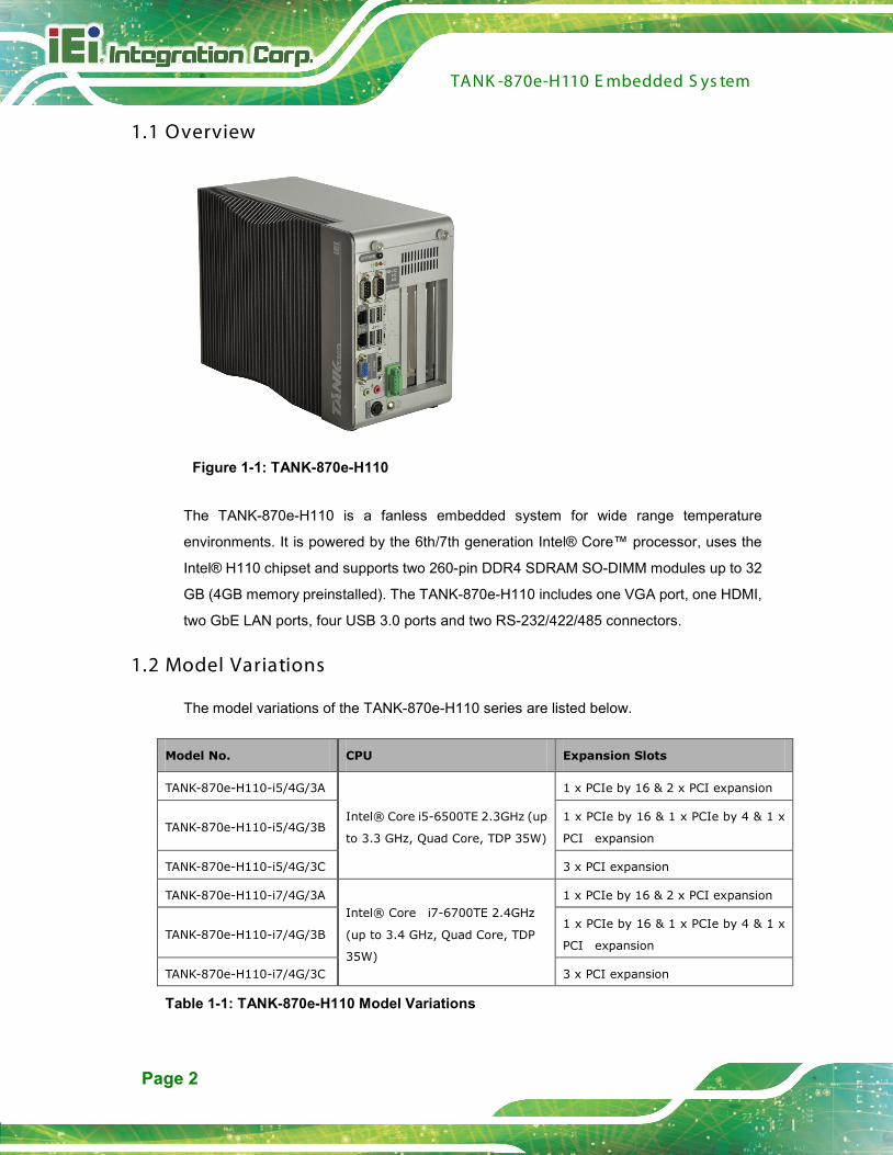
1.1 Overview
Figure 1-1: TANK-870e-H110
The TANK-870e-H110 is a fanless embedded system for wide range temperature
environments. It is powered by the 6th/7th generation Intel® Core™ processor, uses the
Intel® H110 chipset and supports two 260-pin DDR4 SDRAM SO-DIMM modules up to 32
GB (4GB memory preinstalled). The TANK-870e-H110 includes one VGA port, one HDMI,
two GbE LAN ports, four USB 3.0 ports and two RS-232/422/485 connectors.
1.2 Model Variations
The model variations of the TANK-870e-H110 series are listed below.
Model No. CPU Expansion Slots
TANK-870e-H110-i5/4G/3A
Intel® Core i5-6500TE 2.3GHz (up
to 3.3 GHz, Quad Core, TDP 35W)
1 x PCIe by 16 & 2 x PCI expansion
TANK-870e-H110-i5/4G/3B 1 x PCIe by 16 & 1 x PCIe by 4 & 1 x
PCI expansion
TANK-870e-H110-i5/4G/3C 3 x PCI expansion
TANK-870e-H110-i7/4G/3A Intel® Core i7-6700TE 2.4GHz
(up to 3.4 GHz, Quad Core, TDP
35W)
1 x PCIe by 16 & 2 x PCI expansion
TANK-870e-H110-i7/4G/3B 1 x PCIe by 16 & 1 x PCIe by 4 & 1 x
PCI expansion
TANK-870e-H110-i7/4G/3C 3 x PCI expansion
Table 1-1: TANK-870e-H110 Model Variations

TANK -870e-H110 E mbedded S ys tem
Page 3
1.3 F eatures
The TANK-870e-H110 features are listed below:
6th/7th Gen Intel® Core™ processor platform with Intel® H110 chipset and
DDR4 memory
Support dual display VGA+HDMI
On-board internal power connector for providing power to add-on cards
Great flexibility for hardware expansion
1.4 Tec hnic al S pecifications
The TANK-870e-H110 technical specifications are listed in Table 1-2.
S pecific ations
C has s is
C olor Dark silver purple + Silver
Dimens ions (WxHxD) (mm) 132.6 x 255.2 x 190
S ys tem F an Fanless
C has s is C ons truction Extruded aluminum alloy
Motherboard
C P U
Intel 7th Gen Core CPU &
Intel® Core™ i7-6700TE (2.4 GHz, quad-core, TDP=35W)
Intel® Core™ i5-6500TE (2.3 GHz, quad-core, TDP=35W)
C hips et Intel® H110
S ys tem Memory 2 x 260-pin DDR4 SO-DIMM,
one 4 GB pre-installed (system max: 32GB)
Storage
Hard Drive 1 x 2.5'' SATA 6Gb/s HDD/SSD bay
I/O Interfac es
US B 3.0 4
E thernet 2 x RJ-45 PCIe GbE by RTL8111G controller
TANK -870e-H110 E mbedded S ys tem
Page 4
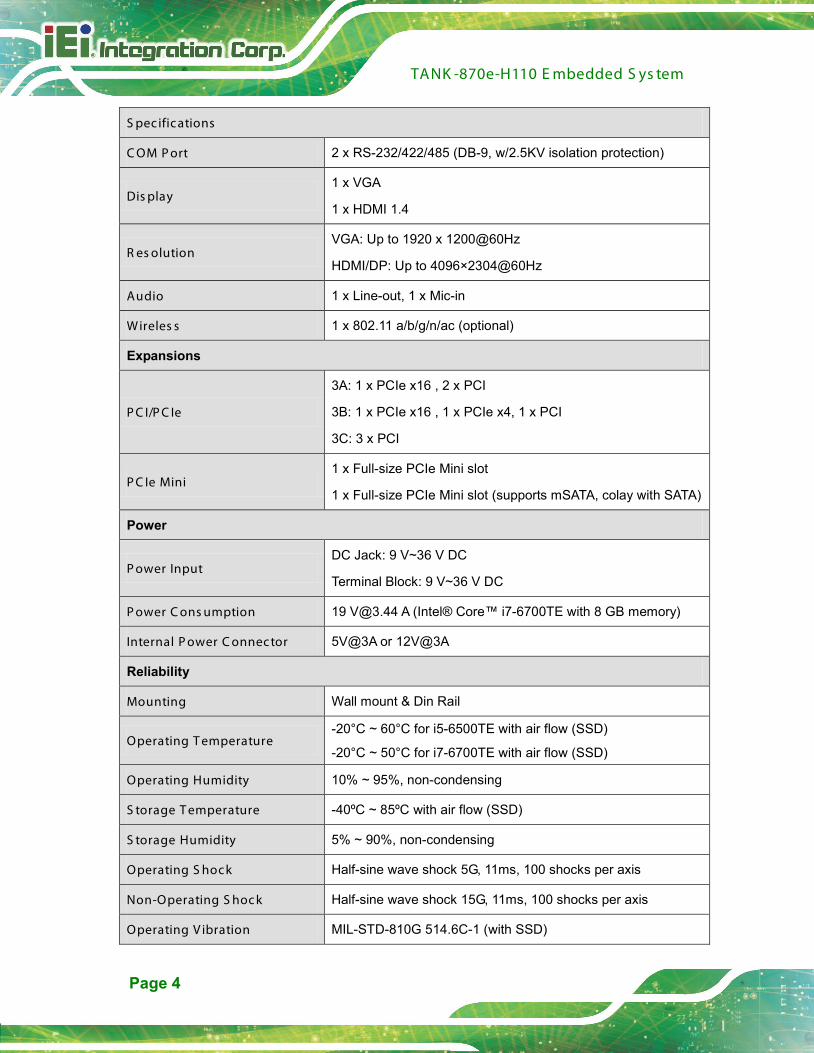
S pecific ations
C OM P ort 2 x RS-232/422/485 (DB-9, w/2.5KV isolation protection)
Dis play 1 x VGA
1 x HDMI 1.4
R es olution VGA: Up to 1920 x 1200@60Hz
HDMI/DP: Up to 4096×2304@60Hz
Audio 1 x Line-out, 1 x Mic-in
Wireles s 1 x 802.11 a/b/g/n/ac (optional)
Expansions
P C I/P C Ie
3A: 1 x PCIe x16 , 2 x PCI
3B: 1 x PCIe x16 , 1 x PCIe x4, 1 x PCI
3C: 3 x PCI
P C Ie Mini 1 x Full-size PCIe Mini slot
1 x Full-size PCIe Mini slot (supports mSATA, colay with SATA)
Power
P ower Input DC Jack: 9 V~36 V DC
Terminal Block: 9 V~36 V DC
P ower C ons umption 19 [email protected] A (Intel® Core™ i7-6700TE with 8 GB memory)
Internal P ower C onnector 5V@3A or 12V@3A
Reliability
Mounting Wall mount & Din Rail
Operating T emperature -20°C ~ 60°C for i5-6500TE with air flow (SSD)
-20°C ~ 50°C for i7-6700TE with air flow (SSD)
Operating Humidity 10% ~ 95%, non-condensing
S torage T emperature -40ºC ~ 85ºC with air flow (SSD)
S torage Humidity 5% ~ 90%, non-condensing
Operating S hock Half-sine wave shock 5G, 11ms, 100 shocks per axis
Non-Operating S hoc k Half-sine wave shock 15G, 11ms, 100 shocks per axis
Operating V ibration MIL-STD-810G 514.6C-1 (with SSD)
TANK -870e-H110 E mbedded S ys tem
Page 5
S pecific ations
Non-Operation V ibration Half-sind mode IEC-60068-2-06
Weight (Net/G ros s ) 4.2 kg/6.3 kg
S afety/E MC CE/FCC
OS
S upported OS
Microsoft® Windows® 8 Embedded,
Microsoft® Windows® Embedded Standard 7 E,
Microsoft® Windows® 10 IoT Enterprise
Table 1-2: Technical Specifications
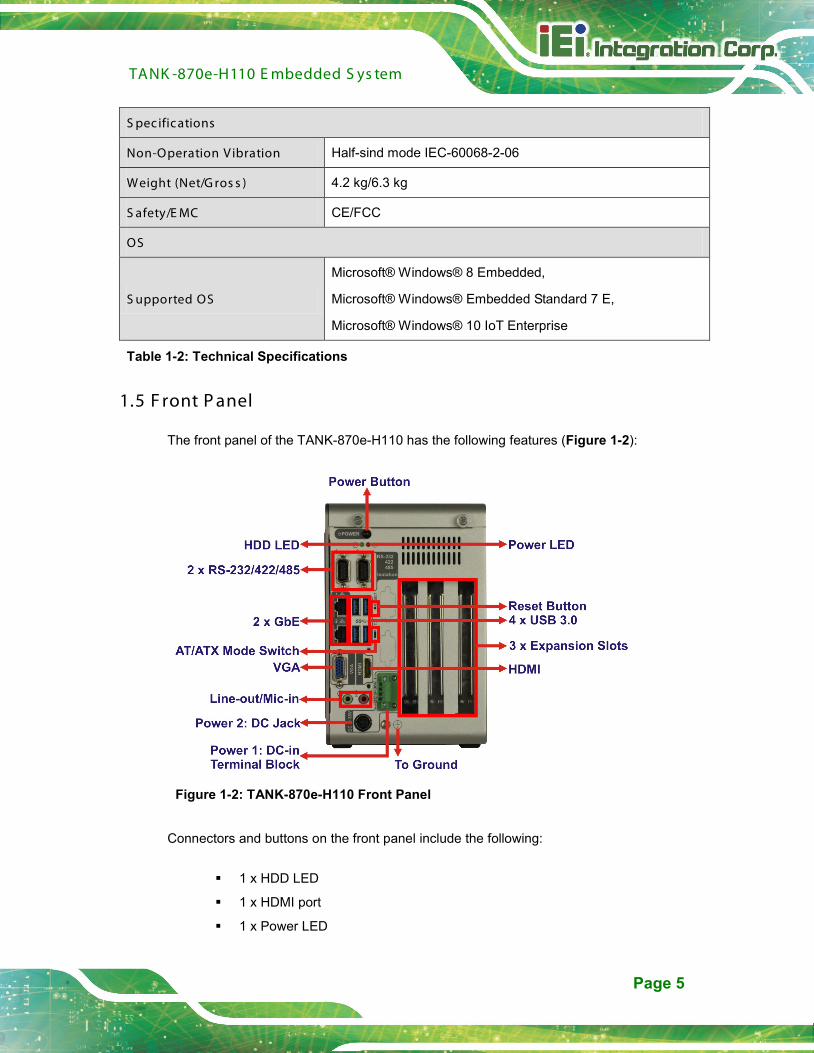
1.5 F ront P anel
The front panel of the TANK-870e-H110 has the following features (Figure 1-2):
Figure 1-2: TANK-870e-H110 Front Panel
Connectors and buttons on the front panel include the following:
1 x HDD LED
1 x HDMI port
1 x Power LED

TANK -870e-H110 E mbedded S ys tem
Page 6
1 x 4-pin power DC jack for 9 V ~ 36 V power input
1 x Power terminal block for 9 V ~ 36 V power input
1 x Mic-in port (pink)
1 x Line-out port (green)
2 x RS-232/422/485 serial ports (DB-9, w/2.5KV isolation protection)
2 x Gigabit Ethernet ports (RJ-45)
4 x USB 3.0 ports
1 x Reset button
1 x Power button
1 x VGA port
1 x To Ground
3 x Expansion slots
1 x AT/ATX mode switch
1.6 R ear P anel
The rear panel of the TANK-870e-H110 has the following features (Figure 1-2):
Figure 1-3: TANK-870e-H110 Rear Panel
TANK -870e-H110 E mbedded S ys tem
Page 7
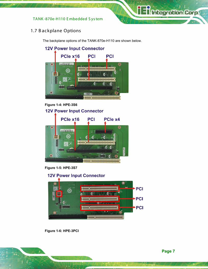
1.7 B ac kplane Options
The backplane options of the TANK-870e-H110 are shown below.
Figure 1-4: HPE-3S6
Figure 1-5: HPE-3S7
Figure 1-6: HPE-3PCI
TANK -870e-H110 E mbedded S ys tem
Page 8
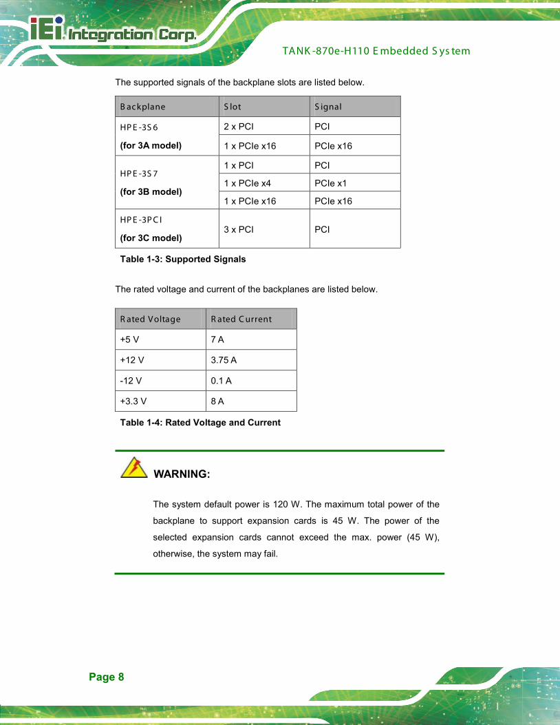
The supported signals of the backplane slots are listed below.
B ackplane S lot S ignal
HP E -3S 6
(for 3A model)
2 x PCI PCI
1 x PCIe x16 PCIe x16
HP E -3S 7
(for 3B model)
1 x PCI PCI
1 x PCIe x4 PCIe x1
1 x PCIe x16 PCIe x16
HP E -3P C I
(for 3C model) 3 x PCI PCI
Table 1-3: Supported Signals
The rated voltage and current of the backplanes are listed below.
R ated Voltage R ated C urrent
+5 V 7 A
+12 V 3.75 A
-12 V 0.1 A
+3.3 V 8 A
Table 1-4: Rated Voltage and Current
WARNING:
The system default power is 120 W. The maximum total power of the
backplane to support expansion cards is 45 W. The power of the
selected expansion cards cannot exceed the max. power (45 W),
otherwise, the system may fail.

TANK -870e-H110 E mbedded S ys tem
Page 9
NOTE:
When using an expansion card with high power consumption, it is
recommended to install an external power supply to the 12V power
input connector on the backplane.
The maximum dimensions of the expansion card should be 190 mm in
length and 110 mm in width.
The TANK-870-Q170 provides the most convenient 4-pin internal power connector for
add-on card usage, adding more flexibility to the embedded system in industrial
environment. The internal power connector supports 5V@3A or 12V@3A power supply.
1.8 P hys ic al Dimens ions
The physical dimensions of the TANK-870e-H110 are shown in Figure 1-7.
Figure 1-7: TANK-870e-H110 Physical Dimensions (millimeters)
TANK -870e-H110 E mbedded S ys tem
Page 10
C hapter
2
2 Unpac king

TANK -870e-H110 E mbedded S ys tem
Page 11
2.1 Anti-s tatic P recautions
WAR NING :
Failure to take ESD precautions during installation may result in
permanent damage to the TANK-870e-H110 and severe injury to the
user.
Electrostatic discharge (ESD) can cause serious damage to electronic components,
including the TANK-870e-H110. Dry climates are especially susceptible to ESD. It is
therefore critical that whenever the TANK-870e-H110 or any other electrical component is
handled, the following anti-static precautions are strictly adhered to.
Wear an anti-static wristband: Wearing a simple anti-static wristband can
help to prevent ESD from damaging the board.
Self-grounding: Before handling the board touch any grounded conducting
material. During the time the board is handled, frequently touch any
conducting materials that are connected to the ground.
Use an anti-static pad: When configuring the TANK-870e-H110, place it on
an antic-static pad. This reduces the possibility of ESD damaging the
TANK-870e-H110.
2.2 Unpac king P recautions
When the TANK-870e-H110 is unpacked, please do the following:
Follow the anti-static precautions outlined in Section 2.1.
Make sure the packing box is facing upwards so the TANK-870e-H110 does
not fall out of the box.
Make sure all the components shown in Section 2.3 are present.
TANK -870e-H110 E mbedded S ys tem
Page 12
2.3 Unpac king C hec klis t
NOT E :
If some of the components listed in the checklist below are missing,
please do not proceed with the installation. Contact the IEI reseller or
vendor you purchased the TANK-870e-H110 from or contact an IEI
sales representative directly. To contact an IEI sales representative,
please send an email to [email protected].
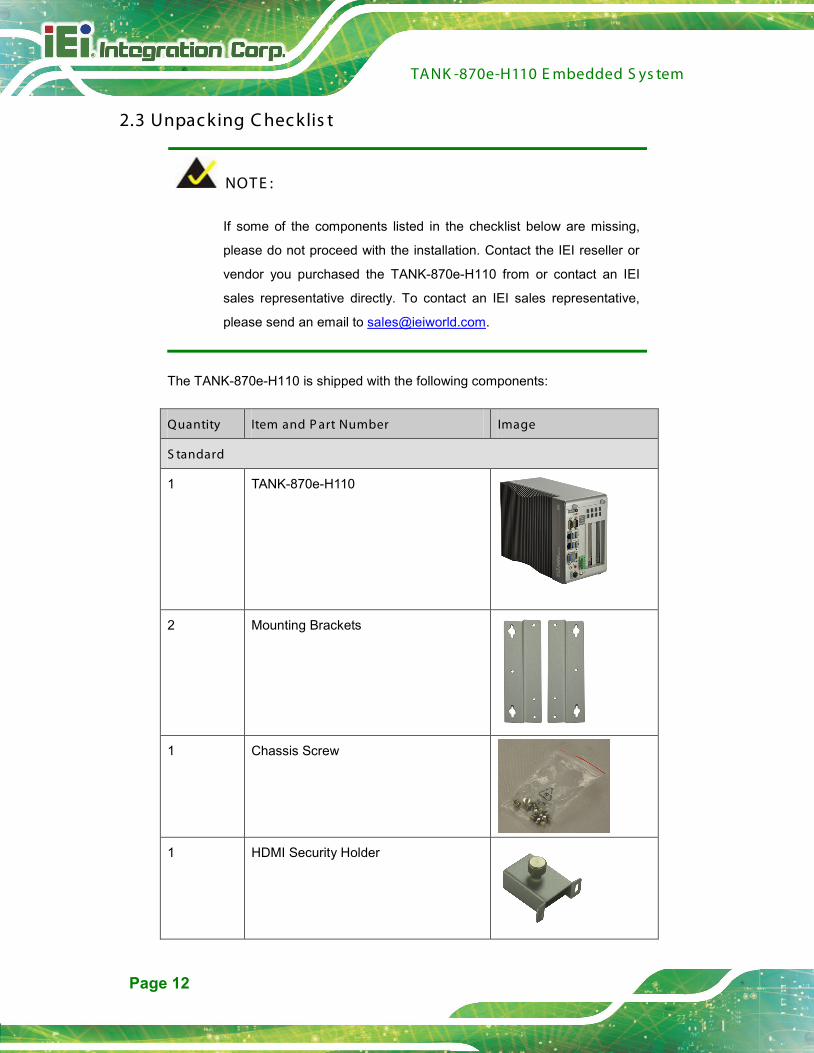
The TANK-870e-H110 is shipped with the following components:
Quantity Item and P art Number Image
S tandard
1 TANK-870e-H110
2 Mounting Brackets
1 Chassis Screw
1 HDMI Security Holder
TANK -870e-H110 E mbedded S ys tem
Page 13
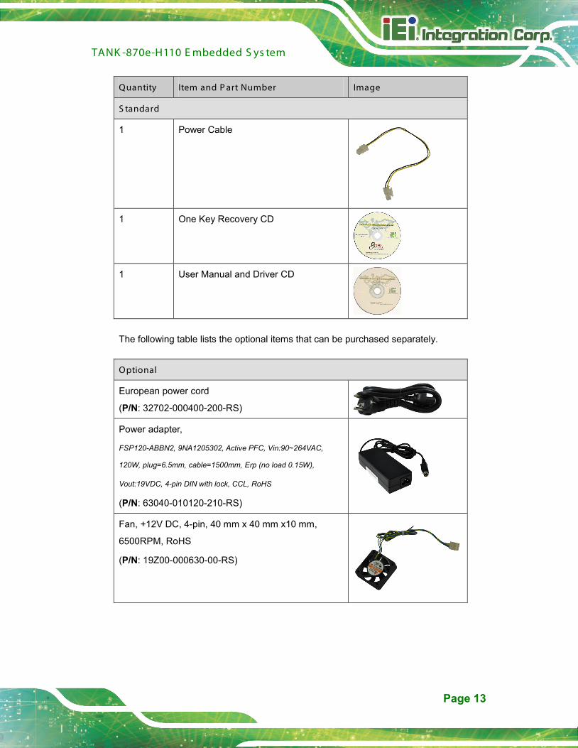
Quantity Item and P art Number Image
S tandard
1 Power Cable
1 One Key Recovery CD
1 User Manual and Driver CD
The following table lists the optional items that can be purchased separately.
Optional
European power cord
(P/N: 32702-000400-200-RS)
Power adapter,
FSP120-ABBN2, 9NA1205302, Active PFC, Vin:90~264VAC,
120W, plug=6.5mm, cable=1500mm, Erp (no load 0.15W),
Vout:19VDC, 4-pin DIN with lock, CCL, RoHS
(P/N: 63040-010120-210-RS)
Fan, +12V DC, 4-pin, 40 mm x 40 mm x10 mm,
6500RPM, RoHS
(P/N: 19Z00-000630-00-RS)
TANK -870e-H110 E mbedded S ys tem
Page 14
Optional
OS Image with Windows® Embedded Standard 7 E
64-bit for TANK-870e-H110 Series, with DVD-ROM,
RoHS
(P/N: TANK-870e-H110-WES7E64-R10)
OS Image with Windows Embedded Standard 10 E
High End 64-bit for TANK-870e-H110-i7 Series, with
DVD-ROM, RoHS
(P/N: TANK-870e-H110-W10E64-H-R10)
OS Image with Windows Embedded Standard 10 E
Value 64-bit for TANK-870e-H110-i5 Series, with
DVD-ROM, RoHS
(P/N: TANK-870e-H110-W10E64-V-R10)

TANK -870e-H110 E mbedded S ys tem
Page 15
C hapter
3
3 Ins tallation

TANK -870e-H110 E mbedded S ys tem
Page 16
3.1 Ins tallation P rec autions
During installation, be aware of the precautions below:
Read the user manual: The user manual provides a complete description of
the TANK-870e-H110, installation instructions and configuration options.
DANGER! Disconnect Power: Power to the TANK-870e-H110 must be
disconnected during the installation process, or before any attempt is made to
access the rear panel. Electric shock and personal injury might occur if the
rear panel of the TANK-870e-H110 is opened while the power cord is still
connected to an electrical outlet.
Qualified Personnel: The TANK-870e-H110 must be installed and operated
only by trained and qualified personnel. Maintenance, upgrades, or repairs
may only be carried out by qualified personnel who are familiar with the
associated dangers.
Air Circulation: Make sure there is sufficient air circulation when installing the
TANK-870e-H110. The TANK-870e-H110’s cooling vents must not be
obstructed by any objects. Blocking the vents can cause overheating of the
TANK-870e-H110. Leave at least 5 cm of clearance around the
TANK-870e-H110 to prevent overheating.
Grounding: The TANK-870e-H110 should be properly grounded. The voltage
feeds must not be overloaded. Adjust the cabling and provide external
overcharge protection per the electrical values indicated on the label attached
to the back of the TANK-870e-H110.
3.2 Hard Dis k Drive (HDD) Ins tallation
To install the hard drive, please follow the steps below:
S tep 1: Loosen the two thumbscrews on the front panel, slide the cover outward, and
then lift the cover up gently (Figure 3-1).

TANK -870e-H110 E mbedded S ys tem
Page 17
Figure 3-1: Unscrew the Cover
S tep 2: Unplug the SATA signal and power cables connected to the TANK-870e-H110,
and then put the cover on a flat surface (Figure 3-2).
Figure 3-2: Remove the Cover from TANK-870e-H110
S tep 3: Attach the HDD to the HDD bracket, and then slide the HDD to connect with the
SATA connector (Figure 3-3).
TANK -870e-H110 E mbedded S ys tem
Page 18
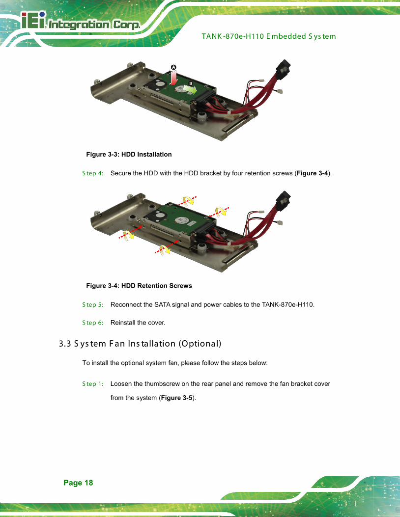
Figure 3-3: HDD Installation
S tep 4: Secure the HDD with the HDD bracket by four retention screws (Figure 3-4).
Figure 3-4: HDD Retention Screws
S tep 5: Reconnect the SATA signal and power cables to the TANK-870e-H110.
S tep 6: Reinstall the cover.
3.3 S ys tem F an Ins tallation (Optional)
To install the optional system fan, please follow the steps below:
S tep 1: Loosen the thumbscrew on the rear panel and remove the fan bracket cover
from the system (Figure 3-5).

TANK -870e-H110 E mbedded S ys tem
Page 19
Figure 3-5: Remove the Fan Bracket Cover from the System
S tep 2: Unscrew the four retention screws that secure the fan bracket to the cover.
(Figure 3-6). Remove the fan bracket from the cover.
Figure 3-6: Remove the Fan Bracket from the Cover
S tep 3: Attach the system fan to the fan bracket and secure it by four retention screws
(Figure 3-7).

TANK -870e-H110 E mbedded S ys tem
Page 20
Figure 3-7: Secure the System Fan to the Fan Bracket
S tep 4: Reinstall the fan bracket with the system fan installed to the cover and secure it
by four retention screws (Figure 3-8).
Figure 3-8: Reinstall the Fan Bracket to the Cover
S tep 5: Loosen the two thumbscrews on the front panel, slide the cover outward, and
then lift the cover up gently (Figure 3-1).
S tep 6: Connect the system fan cable to the CPU_FAN1 connector on the motherboard
of TANK-870e-H110 (Figure 4-1).

TANK -870e-H110 E mbedded S ys tem
Page 21
S tep 7: Reinstall the fan bracket cover to the system and tighten the thumbscrew on the
rear panel.
3.4 Mounting the S ys tem with Mounting B rac kets
To mount the embedded system onto a wall or some other surface using the two mounting
brackets, please follow the steps below.
S tep 1: Turn the embedded system to the left side panel.
S tep 2: Align the two retention screw holes in each bracket with the corresponding
retention screw holes on the bottom surface or the left side panel (Figure 3-9).
Left Side Panel
Figure 3-9: Mounting Bracket Retention Screws
S tep 3: Secure the brackets to the system by inserting two retention screws into each
bracket (Figure 3-9).
S tep 4: Drill holes in the intended installation surface.
S tep 5: Align the mounting holes in the sides of the mounting brackets with the predrilled
holes in the mounting surface.
S tep 6: Insert four retention screws, two in each bracket, to secure the system to the
wall.

TANK -870e-H110 E mbedded S ys tem
Page 22
3.5 E xternal P eripheral Interfac e C onnec tors
Detailed descriptions of the connectors can be found in the subsections below.
3.5.1 AT /AT X P ower Mode S elec tion
The TANK-870e-H110 supports AT and ATX power modes. The setting can be made
through the AT/ATX power mode switch on the external peripheral interface panel as
shown below.
Figure 3-10: AT/ATX Power Mode Switch
3.5.2 Audio C onnec tor
The audio jacks connect to external audio devices.
Line Out port (Green): Connects to a headphone or a speaker. With
multi-channel configurations, this port can also connect to front speakers.
Microphone (Pink): Connects a microphone.

TANK -870e-H110 E mbedded S ys tem
Page 23
Figure 3-11: Audio Connector
3.5.3 HDMI Dis play Devic e C onnec tion
The TANK-870e-H110 has one HDMI connector. The HDMI connector transmits a digital
signal to compatible HDMI display devices such as a TV or computer screen.
3.5.4 L AN C onnec tors
The TANK-870e-H110 has two RJ-45 LAN connectors. The LAN connectors allow
connection to an external network.
Figure 3-12: RJ-45 Ethernet Connector
The RJ-45 Ethernet connector has two status LEDs, one green and one yellow. The green
LED indicates activity on the port and the yellow LED indicates the port is linked. See
Table 3-1.
Activity/Link LED Speed LED
STATUS DESCRIPTION STATUS DESCRIPTION
Off No link Off 10 Mbps connection
Yellow Linked Green 100 Mbps connection
Blinking TX/RX activity Orange 1 Gbps connection
Table 3-1: RJ-45 Ethernet Connector LEDs

TANK -870e-H110 E mbedded S ys tem
Page 24
3.5.5 P ower Input, 4-pin Terminal B lock
The power connector connects the leads of a 9 V~36 V DC power supply into the terminal
block. Make sure that the power and ground wires are attached to the correct sockets of
the connector.
Figure 3-13: 4-pin Terminal Block
3.5.6 P ower Input, 4-pin DIN C onnec tor
The power connector connects to the 9 V~36 V DC power adapter.
Figure 3-14: Power Input Connector
3.5.7 DB -9 R S -232/422/485 S erial P ort C onnec tors
The TANK-870e-H110 has two DB-9 RS-232/422/485 connectors.
3.5.8 US B C onnec tors
The TANK-870e-H110 has four USB 3.0 connectors. The USB ports are for connecting
USB peripheral devices to the system.
3.5.9 V G A C onnec tor
The TANK-870e-H110 has one VGA connector. The VGA connector connects to a monitor
that accepts VGA video input.

TANK -870e-H110 E mbedded S ys tem
Page 25
3.6 P owering On/Off the S ys tem
WARNING:
Make sure a power supply with the correct input voltage is being fed into
the system. Incorrect voltages applied to the system may cause damage to
the internal electronic components and may also cause injury to the user.
Power on the system: press the power button for 2 seconds
Power off the system: press the power button for 5 seconds
Figure 3-15: Power Button
3.7 P ower
There are two power connectors on the rear panel. Power 1 connector is a DIN connector
that can directly connect to a power adapter. Power 2 connector is a 4-pin terminal block.
The supported power input voltages are:
Power 1 (terminal block): 9 V~ 36 V
Power 2 (DC jack): 9 V ~ 36 V

TANK -870e-H110 E mbedded S ys tem
Page 26
Figure 3-16: Power Connectors
WARNING:
The TANK-870e-H110 only support single power input and cannot be
simultaneously connected to two power sources.
TANK -870e-H110 E mbedded S ys tem
Page 27
4 S ys tem Motherboard
Chapter
4
TANK -870e-H110 E mbedded S ys tem
Page 28
4.1 Overview
This chapter details all the jumpers and connectors of the system motherboard.
4.1.1 L ayout
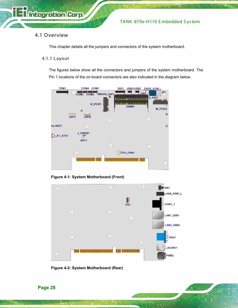
The figures below show all the connectors and jumpers of the system motherboard. The
Pin 1 locations of the on-board connectors are also indicated in the diagram below.
Figure 4-1: System Motherboard (Front)
Figure 4-2: System Motherboard (Rear)
TANK -870e-H110 E mbedded S ys tem
Page 29
4.2 Internal P eripheral C onnec tors
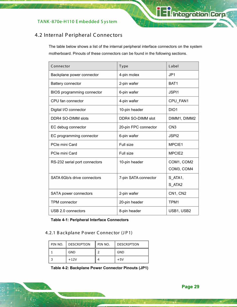
The table below shows a list of the internal peripheral interface connectors on the system
motherboard. Pinouts of these connectors can be found in the following sections.
C onnector T ype L abel
Backplane power connector 4-pin molex JP1
Battery connector 2-pin wafer BAT1
BIOS programming connector 6-pin wafer JSPI1
CPU fan connector 4-pin wafer CPU_FAN1
Digital I/O connector 10-pin header DIO1
DDR4 SO-DIMM slots DDR4 SO-DIMM slot DIMM1, DIMM2
EC debug connector 20-pin FPC connector CN3
EC programming connector 6-pin wafer JSPI2
PCIe mini Card Full size MPCIE1
PCIe mini Card Full size MPCIE2
RS-232 serial port connectors 10-pin header COM1, COM2
COM3, COM4
SATA 6Gb/s drive connectors 7-pin SATA connector S_ATA1,
S_ATA2
SATA power connectors 2-pin wafer CN1, CN2
TPM connector 20-pin header TPM1
USB 2.0 connectors 8-pin header USB1, USB2
Table 4-1: Peripheral Interface Connectors
4.2.1 B ac kplane P ower C onnec tor (J P 1)
PIN NO. DESCRIPTION PIN NO. DESCRIPTION
1 GND 2 GND
3 +12V 4 +5V
Table 4-2: Backplane Power Connector Pinouts (JP1)

TANK -870e-H110 E mbedded S ys tem
Page 30
4.2.2 B attery C onnec tor (B AT 1)
4.2.3 B IOS P rogramming C onnec tor (J S P I1)
PIN NO. DESCRIPTION PIN NO. DESCRIPTION
1 +V3.3M_SPI_CON 2 SPI_CS#0_CN
3 SPI_SO_SW 4 SPI_CLK_SW
5 SPI_SI_SW 6 GND
Table 4-4: BIOS Programming Connector Pinouts (JSPI1)
4.2.4 C P U F an C onnec tor (C P U_FAN1)
PIN NO. DESCRIPTION PIN NO. DESCRIPTION
1 GND 2 +V12S
3 FANIO 4 FANOUT
Table 4-5: CPU Fan Connector Pinouts (CPU_FAN1)
4.2.5 DIO c onnec tor (DIO1)
PIN NO. DESCRIPTION PIN NO. DESCRIPTION
1 GND 2 VCC5
3 DIN7 4 DOUT7
5 DIN6 6 DOUT6
7 DIN5 8 DOUT5
9 DIN4 10 DOUT4
11 DIN3 12 DOUT3
13 DIN2 14 DOUT2
15 DIN1 16 DOUT1
17 DIN0 18 DOUT0
Table 4-6: DIO connector Pinouts (DIO1)
PIN NO. DESCRIPTION PIN NO. DESCRIPTION
1 VBATT 2 GND
Table 4-3: Battery Connector Pinouts (BAT1)

TANK -870e-H110 E mbedded S ys tem
Page 31
4.2.6 E C Debug C onnec tor (C N3)
PIN NO. DESCRIPTION PIN NO. DESCRIPTION
1 KSI0 11 KSO9
2 KSO0 12 KSO10
3 KSO1 13 KSO12
4 KSO2 14 KSI1
5 KSO3 15 KSO11
6 KSO4 16 KSI2
7 KSO5 17 KSI3
8 KSO6 18 GND
9 KSO7 19 GND
10 KSO8 20 GND
Table 4-7: EC Debug Connector Pinouts (CN3)
4.2.7 E C P rogramming C onnec tor (J S P I2)
PIN NO. DESCRIPTION PIN NO. DESCRIPTION
1 +V3.3M_SPI_CON_EC 2 SPI_CS#0_CN_EC
3 SPI_SO_SW_EC 4 SPI_CLK_SW_EC
5 SPI_SI_SW_EC 6 GND
Table 4-8: EC Programming Connector Pinouts (JSPI2)
4.2.8 R S -232 S erial P ort C onnec tors (C OM1)
PIN NO. DESCRIPTION PIN NO. DESCRIPTION
1 DCD6 2 DSR6
3 RX6 4 RTS6
5 TX6 6 CTS6
7 DTR6 8 RI6
9 GND 10 GND
Table 4-9: RS-232 Serial Port Connectors Pinouts (COM1)

TANK -870e-H110 E mbedded S ys tem
Page 32
4.2.9 R S -232 S erial P ort C onnec tors (C OM2)
PIN NO. DESCRIPTION PIN NO. DESCRIPTION
1 DCD2 2 DSR2
3 RX2 4 RTS2
5 TX2 6 CTS2
7 DTR2 8 RI2
9 GND 10 GND
Table 4-10: RS-232 Serial Port Connectors Pinouts (COM2)
4.2.10 R S -232 S erial P ort C onnec tors (C OM3)
PIN NO. DESCRIPTION PIN NO. DESCRIPTION
1 DCD3 2 DSR3
3 RX3 4 RTS3
5 TX3 6 CTS3
7 DTR3 8 RI3
9 GND 10 GND
Table 4-11: RS-232 Serial Port Connectors Pinouts (COM3)
4.2.11 R S -232 S erial P ort C onnec tors (C OM4)
PIN NO. DESCRIPTION PIN NO. DESCRIPTION
1 DCD4 2 DSR4
3 RX4 4 RTS4
5 TX4 6 CTS4
7 DTR4 8 RI4
9 GND 10 GND
Table 4-12: RS-232 Serial Port Connectors Pinouts (COM4)

TANK -870e-H110 E mbedded S ys tem
Page 33
4.2.12 S ATA P ower C onnec tors (C N1, C N2)
4.2.13 T P M C onnec tor (T P M1)
PIN NO. DESCRIPTION PIN NO. DESCRIPTION
1 CLK 2 GND
3 LPC_FRAME# 4 NC
5 PLT_GATED_RST# 6 VCC5
7 LPC_AD3 8 LPC_AD2
9 VCC3 10 LPC_AD1
11 LPC_AD0 12 GND
13 SMB_CLK 14 SMB_DATA
15 V3P3A 16 INT_SERIRQ
17 GND 18 PM_CLKRUN#
19 LPCPD_N 20 TPM_DRQ#0
Table 4-14: TPM Connector Pinouts (TPM1)
4.2.14 US B 2.0 c onnec tors (US B 1)
PIN NO. DESCRIPTION PIN NO. DESCRIPTION
1 VCC_USB 2 GND
3 -DATA5 4 +DATA6
5 +DATA5 6 -DATA6
7 GND 8 VCC_USB
Table 4-15: USB 2.0 connectors Pinouts (USB1)
4.2.15 US B 2.0 c onnec tors (US B 2)
PIN NO. DESCRIPTION PIN NO. DESCRIPTION
1 VCC_USB 2 GND
3 -DATA7 4 +DATA8
PIN NO. DESCRIPTION PIN NO. DESCRIPTION
1 +V5S 2 GND
Table 4-13: SATA Power Connectors Pinouts (CN1, CN2)

TANK -870e-H110 E mbedded S ys tem
Page 34
5 +DATA7 6 -DATA8
7 GND 8 VCC_USB
Table 4-16: USB 2.0 connectors Pinouts (USB2)
4.3 E xternal Interfac e P anel C onnec tors
The table below shows a list of the external interface panel connectors on the system
motherboard. Pinouts of these connectors can be found in the following sections.
C onnector T ype L abel
Audio jack (mic, line-out) Audio jack JAUDIO1
Ethernet and USB3.0 connectors RJ-45, USB 3.0 port LAN1_USB1, LAN2_USB2
HDMI connector Type A HDMI1
Power connector DC jack PWR2
Power connector 4-pin terminal block PWR1
RS-232 serial port connectors Dual DB-9 w/isolation COM1_1
VGA connector DB-15 VGA1
Table 4-17: Rear Panel Connectors
4.3.1 Audio J ac k (J AUDIO1)
PIN NO. DESCRIPTION PIN NO. DESCRIPTION
1 GND 2 LMIC1-CONN-L
3 GND 4 MIC1-JD
5 LMIC1-CONN-R 22 LFRONT-L
23 GND 24 FRONT-JD
25 LFRONT-R
Table 4-18: Audio Jack Pinouts (JAUDIO1)
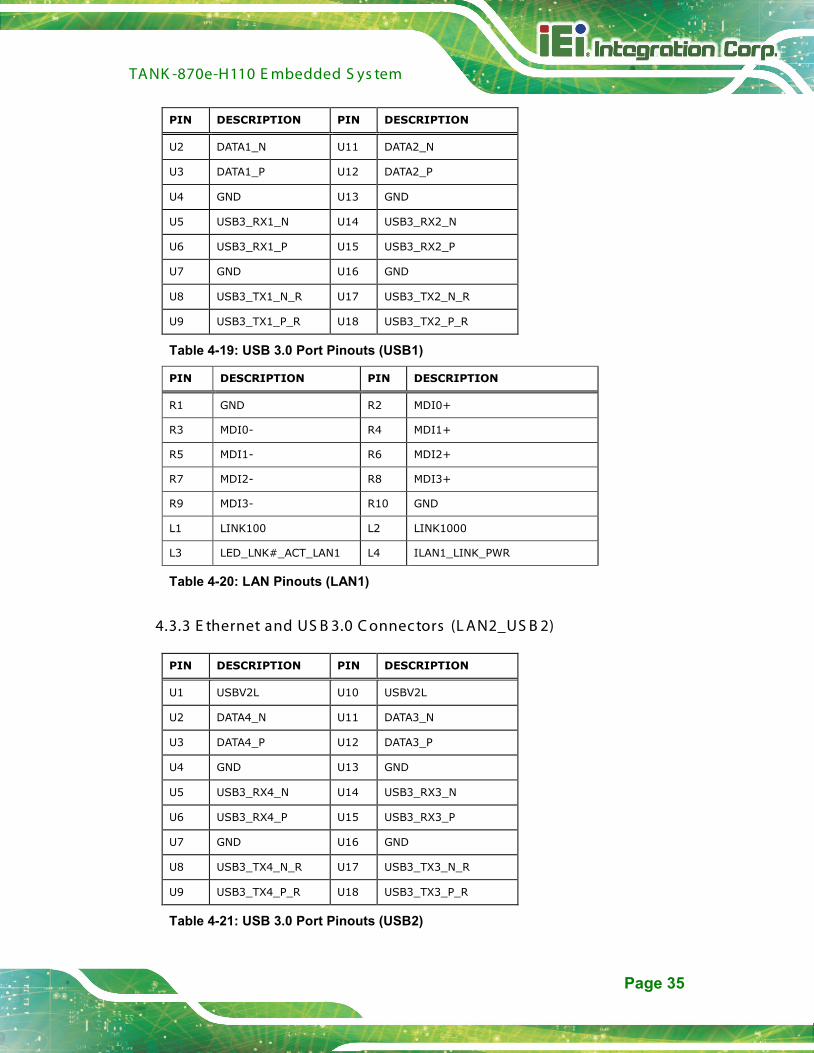
4.3.2 E thernet and US B 3.0 C onnec tors (L AN1_US B 1)
PIN DESCRIPTION PIN DESCRIPTION
U1 USBV0L U10 USBV0L
TANK -870e-H110 E mbedded S ys tem
Page 35
PIN DESCRIPTION PIN DESCRIPTION
U2 DATA1_N U11 DATA2_N
U3 DATA1_P U12 DATA2_P
U4 GND U13 GND
U5 USB3_RX1_N U14 USB3_RX2_N
U6 USB3_RX1_P U15 USB3_RX2_P
U7 GND U16 GND
U8 USB3_TX1_N_R U17 USB3_TX2_N_R
U9 USB3_TX1_P_R U18 USB3_TX2_P_R
Table 4-19: USB 3.0 Port Pinouts (USB1)
PIN DESCRIPTION PIN DESCRIPTION
R1 GND R2 MDI0+
R3 MDI0- R4 MDI1+
R5 MDI1- R6 MDI2+
R7 MDI2- R8 MDI3+
R9 MDI3- R10 GND
L1 LINK100 L2 LINK1000
L3 LED_LNK#_ACT_LAN1 L4 ILAN1_LINK_PWR
Table 4-20: LAN Pinouts (LAN1)
4.3.3 E thernet and US B 3.0 C onnec tors (L AN2_US B 2)
PIN DESCRIPTION PIN DESCRIPTION
U1 USBV2L U10 USBV2L
U2 DATA4_N U11 DATA3_N
U3 DATA4_P U12 DATA3_P
U4 GND U13 GND
U5 USB3_RX4_N U14 USB3_RX3_N
U6 USB3_RX4_P U15 USB3_RX3_P
U7 GND U16 GND
U8 USB3_TX4_N_R U17 USB3_TX3_N_R
U9 USB3_TX4_P_R U18 USB3_TX3_P_R
Table 4-21: USB 3.0 Port Pinouts (USB2)

TANK -870e-H110 E mbedded S ys tem
Page 36
PIN DESCRIPTION PIN DESCRIPTION
R1 GND R2 MDI0+_LAN2
R3 MDI0-_LAN2 R4 MDI1+_LAN2
R5 MDI1-_LAN2 R6 MDI2+_LAN2
R7 MDI2-_LAN2 R8 MDI3+_LAN2
R9 MDI3-_LAN2 R10 GND
L1 LINK100_LAN2 L2 LINK1000_LAN2
L3 LED_LNK#_ACT_LAN2 L4 LAN2_LINK_PWR
Table 4-22: LAN Pinouts (LAN2)
4.3.4 HDMI C onnec tor (HDMI1)
PIN NO. DESCRIPTION PIN NO. DESCRIPTION
1 HDMI_DATA2-1_L 2 GND
3 HDMI_DATA2#-1_L 4 HDMI_DATA1-1_L
5 GND 6 HDMI_DATA1#-1_L
7 HDMI_DATA0-1_L 8 GND
9 HDMI_DATA0#-1_L 10 HDMI_CLK-1_L
11 GND 12 HDMI_CLK#-1_L
13 NC 14 NC
15 HDMI_SCL-1 16 HDMI_SDA-1
17 GND 18 +V5S
19 HDMI_HPD-1
Table 4-23: HDMI Connector Pinouts (HDMI1)
4.3.5 P ower C onnec tor (P WR 2)
PIN NO. DESCRIPTION PIN NO. DESCRIPTION
1 DC_IN 2 GND
3 DC_IN 4 GND
5 GND
Table 4-24: Power Connector Pinouts (PWR2)

TANK -870e-H110 E mbedded S ys tem
Page 37
4.3.6 P ower C onnec tor (P WR 1)
PIN NO. DESCRIPTION PIN NO. DESCRIPTION
1 GND 2 GND
3 DC_IN 4 DC_IN
Table 4-25: Power Connector Pinouts (PWR1)
4.3.7 R S -232/422/485 S erial P ort C onnec tor (C OM1_1)
PIN NO. RS-232 RS-422 RS-485
1(10) DCD TXD422# TXD485#
2(11) RX TXD422+ TXD485+
3(12) TX RXD422+ --
4(13) DTR RXD422# --
5(14) GND -- --
6(15) DSR -- --
7(16) RTS -- --
8(17) CTS -- --
9(18) RI -- --
Table 4-26: RS-232/422/485 Serial Port Connector Pinout (COM5_6)
4.3.8 V G A C onnec tor (V G A1)
PIN NO. DESCRIPTION PIN NO. DESCRIPTION
1 Red 2 Green
3 Blue 4 NC
5 GND 6 GND
7 GND 8 GND
9 CRT_VCC 10 CRT_PLUG#
11 NC 12 5VDDCDA
13 5HSYNC 14 5VSYNC
15 5VDDCLK
Table 4-27: VGA Connector Pinouts (VGA1)

TANK -870e-H110 E mbedded S ys tem
Page 38
4.4 J umper S ettings
The jumpers on the system motherboard are listed in Table 4-28.
C onnector T ype L abel
AT/ATX Mode Select switch J_AT_ATX1
Clear CMOS setup button J_CMOS1
M-SATA Switch Auto-Detect 2-pin header MSATA_SW1
Power Switch Button button SW1
System Reset Button button RST1
Table 4-28: Jumper
4.4.1 AT /AT X Mode S elect (J _AT _AT X1)
Pin Description
A-B ATX mode (Default)
B-C AT mode
Table 4-29: AT/ATX Mode Select Jumper Settings (J_AT_ATX1)
4.4.2 C lear C MOS S etup (J _C MOS 1)
Pin Description
Open Keep CMOS Setup (Default)
Press Clear CMOS Setup
Table 4-30: Clear CMOS Setup Jumper Settings (J_CMOS1)
4.4.3 M-S ATA S witc h Auto-Detec t (MS ATA_S W1)
Pin Description
Open Auto Detect
Short M-SATA select
Table 4-31: M-SATA Switch Auto-Detect Jumper Settings (MSATA_SW1)
TANK -870e-H110 E mbedded S ys tem
Page 39
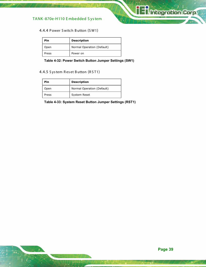
4.4.4 P ower S witch B utton (S W1)
Pin Description
Open Normal Operation (Default)
Press Power on
Table 4-32: Power Switch Button Jumper Settings (SW1)
4.4.5 S ys tem R es et B utton (R S T1)
Pin Description
Open Normal Operation (Default)
Press System Reset
Table 4-33: System Reset Button Jumper Settings (RST1)
TANK -870e-H110 E mbedded S ys tem
Page 40
C hapter
5
5 B IOS
TANK -870e-H110 E mbedded S ys tem
Page 41
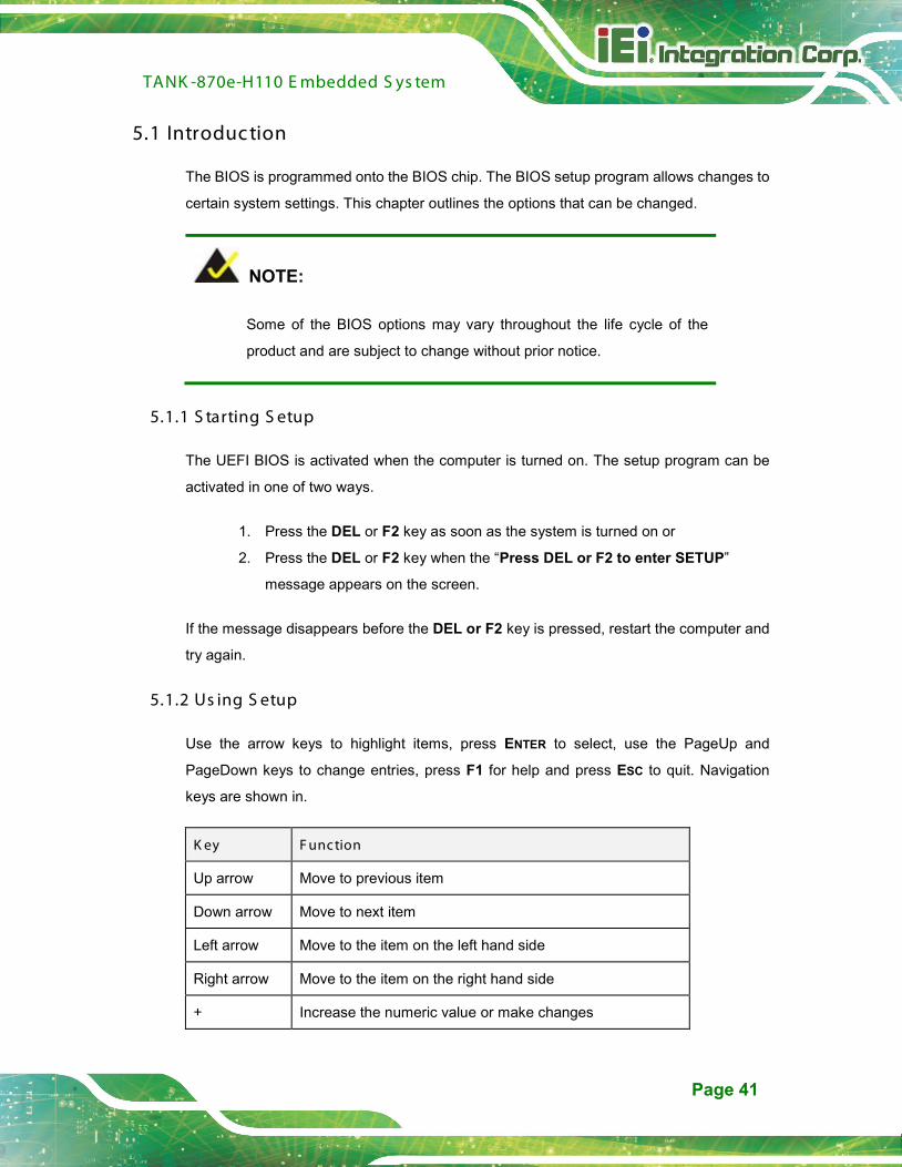
5.1 Introduc tion
The BIOS is programmed onto the BIOS chip. The BIOS setup program allows changes to
certain system settings. This chapter outlines the options that can be changed.
NOTE:
Some of the BIOS options may vary throughout the life cycle of the
product and are subject to change without prior notice.
5.1.1 S tarting S etup
The UEFI BIOS is activated when the computer is turned on. The setup program can be
activated in one of two ways.
1. Press the DEL or F2 key as soon as the system is turned on or
2. Press the DEL or F2 key when the “Press DEL or F2 to enter SETUP”
message appears on the screen.
If the message disappears before the DEL or F2 key is pressed, restart the computer and
try again.
5.1.2 Us ing S etup
Use the arrow keys to highlight items, press ENTER to select, use the PageUp and
PageDown keys to change entries, press F1 for help and press ESC to quit. Navigation
keys are shown in.
K ey F unction
Up arrow Move to previous item
Down arrow Move to next item
Left arrow Move to the item on the left hand side
Right arrow Move to the item on the right hand side
+ Increase the numeric value or make changes

TANK -870e-H110 E mbedded S ys tem
Page 42
K ey F unction
- Decrease the numeric value or make changes
Page Up key Increase the numeric value or make changes
Page Dn key Decrease the numeric value or make changes
Esc key Main Menu – Quit and not save changes into CMOS
Status Page Setup Menu and Option Page Setup Menu --
Exit current page and return to Main Menu
F1 General help, only for Status Page Setup Menu and Option
Page Setup Menu
F2 Previous values
F3 Load optimized defaults
F4 Save changes and Exit BIOS
Table 5-1: BIOS Navigation Keys
5.1.3 G etting Help
When F1 is pressed a small help window describing the appropriate keys to use and the
possible selections for the highlighted item appears. To exit the Help Window press ESC or
the F1 key again.
5.1.4 Unable to R eboot after C onfiguration C hanges
If the computer cannot boot after changes to the system configuration is made, CMOS
defaults. Use the jumper described in Chapter 2.
5.1.5 B IOS Menu B ar
The menu bar on top of the BIOS screen has the following main items:
Main – Changes the basic system configuration.
Advanced – Changes the advanced system settings.
Chipset – Changes the chipset settings.
Boot – Changes the system boot configuration.
Security – Sets User and Supervisor Passwords.

TANK -870e-H110 E mbedded S ys tem
Page 43
Save & Exit – Selects exit options and loads default settings.
The following sections completely describe the configuration options found in the menu
items at the top of the BIOS screen and listed above.

TANK -870e-H110 E mbedded S ys tem
Page 44
5.2 Main
The Main BIOS menu (BIOS Menu 1) appears when the BIOS Setup program is entered.
The Main menu gives an overview of the basic system information.
Aptio Setup Utility – Copyright (C) 2017 American Megatrends, Inc. Main Advanced Chipset Security Boot Save & Exit
BIOS Information BIOS Vendor American Megatrends Core Version 5.12 Compliency UEFI 2.6; PI 1.4 Project Version SEU6AR31.bin Build Date 06/07/2017 14:31:23 Access Level Administrator iWDD Vendor iEi iWDD Version SEU6ER10.bin IEI QTS/IPC Status IPC Board Information Board ID SAG7 Fab ID V1.02 LAN PHY Revision N/A Processor Information Name Skylake DT Type Intel(R) Core(TM)
i5-6500TE CPU @ 2.30GHz Speed 2300 MHz ID 0x506E3 Stepping R0/S0/N0 Package Not Implemented Yet Number of Processors 4Core(s) / 4Thread(s) Microcode Revision BA GT Info GT2(0x1912) IGFX VBIOS Version 1049 IGFX GOP Version N/A Memory RC Version 2.0.0.6 Total Memory 4096 MB Memory Frequency 2133 MHz PCH Information Name SKL PCH-H PCH SKU H110 Stepping D1 Hsio Revision 52 Package Not Implemented Yet TXT Capability of Platform/PCH Supported Production Type Production Dual Output Fast Read support Not supported Read ID/Status Clock Freq 17 MHz Write and Erase Clock Freq 48 MHz Fast Read Clock Freq 48 MHz Fast Read support Supported Read Clock Freq 17 MHz Number of Components 1 Component SPI Component 0 Density 16 MHz ME FW Version 11.7.0.1261 ME Firmware SKU Corporate SKU System Date [Mon 11/28/2016] System Time [15:43:27]
Set the Date. Use Tab to switch between Data elements. ---------------------- : Select Screen ↑ ↓: Select Item Enter Select +/-: Change Opt. F1: General Help F2: Previous Values F3: Optimized Defaults F4: Save & Exit ESC: Exit
Version 2.18.1263. Copyright (C) 2017 American Megatrends, Inc.
TANK -870e-H110 E mbedded S ys tem
Page 45
BIOS Menu 1: Main
The Main menu has two user configurable fields:
S ys tem Date [xx/xx/xx]
Use the System Date option to set the system date. Manually enter the day, month and
year.
S ys tem T ime [xx: xx: xx]
Use the System Time option to set the system time. Manually enter the hours, minutes
and seconds.
5.3 Advanc ed
Use the Advanced menu (BIOS Menu 2) to configure the CPU and peripheral devices
through the following sub-menus:
WAR NING !
Setting the wrong values in the sections below may cause the system
to malfunction. Make sure that the settings made are compatible with
the hardware.

TANK -870e-H110 E mbedded S ys tem
Page 46
Aptio Setup Utility – Copyright (C) 2017 American Megatrends, Inc. Advanced
> CPU Configuration > Trusted Computing > ACPI Settings > SATA Configuration > F81866 Super IO Configuration > RTC Wake Settings > Serial Port Console Redirection > Intel TXT Information > USB Configuration > iEi Feature > iWDD H/M Monitor
CPU Configuration Parameters ---------------------- : Select Screen ↑ ↓: Select Item Enter Select +/-: Change Opt. F1: General Help F2: Previous Values F3: Optimized Defaults F4: Save & Exit ESC: Exit
Version 2.18.1263. Copyright (C) 2017 American Megatrends, Inc.
BIOS Menu 2: Advanced
5.3.1 C P U C onfiguration
Use the CPU Configuration menu (BIOS Menu 3) to enter the CPU Information
submenu or enable Intel Virtualization Technology.

TANK -870e-H110 E mbedded S ys tem
Page 47
Aptio Setup Utility – Copyright (C) 2017 American Megatrends, Inc. Advanced
CPU Configuration Type Intel(R) Core(TM)
i5-6500TE CPU @ 2.30GHz ID 0x506E3 Speed 2300 MHz L1 Data Cache 32 kB x 4 L1 Code Cache 32 kB x 4 L2 Cache 256 kB x 4 L3 Cache 6 MB L4 Cache N/A Intel VT-x Technology Supported Intel SMX Technology Supported Intel(VMX)Virtualization [Disabled] Technology Active Processor Cores [All] EIST [Enabled] C states [Disabled]
When enabled, a VMM can utilize the additional hardware capabilities provided by Vanderpool Technology. ---------------------- : Select Screen ↑ ↓: Select Item Enter Select +/-: Change Opt. F1: General Help F2: Previous Values F3: Optimized Defaults F4: Save & Exit ESC: Exit
Version 2.18.1263. Copyright (C) 2017 American Megatrends, Inc.
BIOS Menu 3: CPU Configuration
The CPU Configuration menu (BIOS Menu 3) lists the following CPU details:
Type: Lists the brand name of the CPU being used
ID: Lists the CPU ID.
Speed: Lists the CPU processing speed.
L1 Data Cache: Lists the amount of data storage space on the L1 cache.
L1 Instruction Cache: Lists the amount of instruction storage space on the L1
cache.
L2 Cache: Lists the amount of storage space on the L2 cache.
L3 Cache: Lists the amount of storage space on the L3 cache.
L4 Cache: Lists the amount of storage space on the L4 cache.
VMX: Indicates if Intel Virtualization Technology is supported by the CPU.
SMX/TXT: Indicates if Intel SMX/TXT Technology is supported by the CPU.

TANK -870e-H110 E mbedded S ys tem
Page 48
Intel (VMX) Virtualization Technology [Dis abled]
Use the Intel (VMX) Virtualization Technology option to enable or disable virtualization
on the system. When combined with third party software, Intel Virtualization technology
allows several OSs to run on the same system at the same time.
Disabled DEFAULT Disables Intel Virtualization Technology.
Enabled Enables Intel Virtualization Technology.
Active P roces s or C ores [All]
Use the Active Processor Cores option to configure the number of the active processor
cores.
All DEFAULT Active all of the processor cores
1 Active one of the processor cores
2 Active two of the processor cores
3 Active three of the processor cores
E IS T [E nabled]
Use the EIST option to enable or disable the Intel Speed Step Technology.
Disabled Disables the Intel Speed Step Technology.
Enabled DEFAULT Enables the Intel Speed Step Technology.
C s tates [Dis abled]
Use the C states option to enable or disable C states.
Disabled DEFAULT Disables C states.
Enabled Enables C states.
TANK -870e-H110 E mbedded S ys tem
Page 49
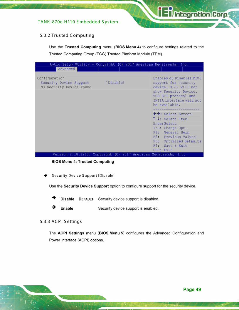
5.3.2 Trus ted C omputing
Use the Trusted Computing menu (BIOS Menu 4) to configure settings related to the
Trusted Computing Group (TCG) Trusted Platform Module (TPM).
Aptio Setup Utility – Copyright (C) 2017 American Megatrends, Inc. Advanced
Configuration Security Device Support [Disable] NO Security Device Found
Enables or Disables BIOS support for security device. O.S. will not show Security Device. TCG EFI protocol and INT1A interface will not be available. ---------------------- : Select Screen ↑ ↓: Select Item Enter Select +/-: Change Opt. F1: General Help F2: Previous Values F3: Optimized Defaults F4: Save & Exit ESC: Exit
Version 2.18.1263. Copyright (C) 2017 American Megatrends, Inc.
BIOS Menu 4: Trusted Computing
S ec urity Devic e S upport [Dis able]
Use the Security Device Support option to configure support for the security device.
Disable DEFAULT Security device support is disabled.
Enable Security device support is enabled.
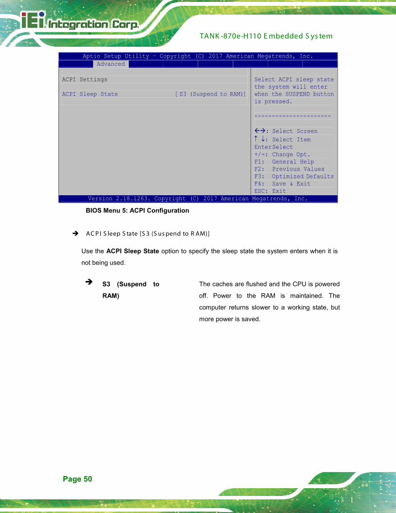
5.3.3 AC P I S ettings
The ACPI Settings menu (BIOS Menu 5) configures the Advanced Configuration and
Power Interface (ACPI) options.
TANK -870e-H110 E mbedded S ys tem
Page 50
Aptio Setup Utility – Copyright (C) 2017 American Megatrends, Inc. Advanced
ACPI Settings ACPI Sleep State [S3 (Suspend to RAM)]
Select ACPI sleep state the system will enter when the SUSPEND button is pressed. ---------------------- : Select Screen ↑ ↓: Select Item Enter Select +/-: Change Opt. F1: General Help F2: Previous Values F3: Optimized Defaults F4: Save & Exit ESC: Exit
Version 2.18.1263. Copyright (C) 2017 American Megatrends, Inc.
BIOS Menu 5: ACPI Configuration
AC P I S leep S tate [S 3 (S us pend to R AM)]
Use the ACPI Sleep State option to specify the sleep state the system enters when it is
not being used.
S3 (Suspend to
RAM)
The caches are flushed and the CPU is powered
off. Power to the RAM is maintained. The
computer returns slower to a working state, but
more power is saved.
TANK -870e-H110 E mbedded S ys tem
Page 51
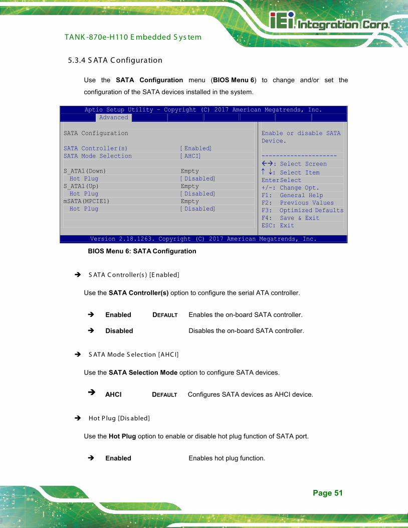
5.3.4 S ATA C onfiguration
Use the SATA Configuration menu (BIOS Menu 6) to change and/or set the
configuration of the SATA devices installed in the system.
Aptio Setup Utility – Copyright (C) 2017 American Megatrends, Inc. Advanced
SATA Configuration SATA Controller(s) [Enabled] SATA Mode Selection [AHCI] S_ATA1(Down) Empty Hot Plug [Disabled]
S_ATA1(Up) Empty Hot Plug [Disabled]
mSATA(MPCIE1) Empty Hot Plug [Disabled]
Enable or disable SATA Device. --------------------- : Select Screen ↑ ↓: Select Item Enter Select +/-: Change Opt. F1: General Help F2: Previous Values F3: Optimized Defaults F4: Save & Exit ESC: Exit
Version 2.18.1263. Copyright (C) 2017 American Megatrends, Inc.
BIOS Menu 6: SATA Configuration
S ATA C ontroller(s ) [E nabled]
Use the SATA Controller(s) option to configure the serial ATA controller.
Enabled DEFAULT Enables the on-board SATA controller.
Disabled Disables the on-board SATA controller.
S ATA Mode S elec tion [AHC I]
Use the SATA Selection Mode option to configure SATA devices.
AHCI DEFAULT Configures SATA devices as AHCI device.
Hot P lug [Dis abled]
Use the Hot Plug option to enable or disable hot plug function of SATA port.
Enabled Enables hot plug function.

TANK -870e-H110 E mbedded S ys tem
Page 52
Disabled DEFAULT Disables hot plug function.
5.3.5 F 81866 S uper IO C onfiguration
Use the F81866 Super IO Configuration menu (BIOS Menu 7) to set or change the
configurations for the serial ports.
Aptio Setup Utility – Copyright (C) 2017 American Megatrends, Inc. Advanced
F81866 Super IO Configuration F81866 Super IO Chip F81866 > Serial Port 1 Configuration > Serial Port 2 Configuration > Serial Port 3 Configuration > Serial Port 4 Configuration > Serial Port 5 Configuration > Serial Port 6 Configuration
Set Parameters of Serial Port 1 (COMA) --------------------- : Select Screen ↑ ↓: Select Item Enter Select +/-: Change Opt. F1: General Help F2: Previous Values F3: Optimized Defaults F4: Save & Exit ESC: Exit
Version 2.18.1263. Copyright (C) 2017 American Megatrends, Inc.
BIOS Menu 7: F81866 Super IO Configuration

TANK -870e-H110 E mbedded S ys tem
Page 53
5.3.5.1 S erial P ort n C onfiguration
Use the Serial Port n Configuration menu (BIOS Menu 8) to configure the serial port n.
Aptio Setup Utility – Copyright (C) 2017 American Megatrends, Inc. Advanced
Serial Port n Configuration Serial Port [Enabled] Device Settings IO=3F8h; IRQ=4 Change Settings [Auto]
Enable or Disable Serial Port (COM) --------------------- : Select Screen ↑ ↓: Select Item Enter Select +/-: Change Opt. F1: General Help F2: Previous Values F3: Optimized Defaults F4: Save & Exit ESC: Exit
Version 2.18.1263. Copyright (C) 2017 American Megatrends, Inc.
BIOS Menu 8: Serial Port n Configuration Menu
5.3.5.1.1 S erial P ort 1 C onfiguration
S erial P ort [E nabled]
Use the Serial Port option to enable or disable the serial port.
Disabled Disable the serial port
Enabled DEFAULT Enable the serial port
C hange S ettings [Auto]
Use the Change Settings option to change the serial port IO port address and interrupt
address.
Auto DEFAULT The serial port IO port address and interrupt
address are automatically detected.
IO=3F8h; IRQ=4 Serial Port I/O port address is 3F8h and the
interrupt address is IRQ4

TANK -870e-H110 E mbedded S ys tem
Page 54
IO=3F8h; IRQ=3, 4,
5, 6, 7, 9, 10, 11,12
Serial Port I/O port address is 3F8h and the
interrupt address is IRQ3, 4, 5, 6, 7, 9, 10, 11,12
IO=2F8h; IRQ=3, 4,
5, 6, 7, 9, 10, 11,12
Serial Port I/O port address is 2F8h and the
interrupt address is IRQ3, 4, 5, 6, 7, 9, 10, 11,12
IO=3E8h; IRQ=3, 4,
5, 6, 7, 9, 10, 11,12
Serial Port I/O port address is 3E8h and the
interrupt address is IRQ3, 4, 5, 6, 7, 9, 10, 11,12
IO=2E8h; IRQ=3, 4,
5, 6, 7, 9, 10, 11,12
Serial Port I/O port address is 2E8h and the
interrupt address is IRQ3, 4, 5, 6, 7, 9, 10, 11,12
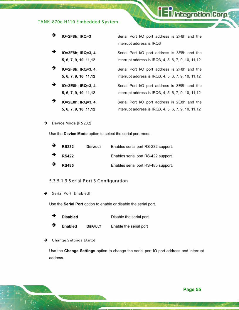
Device Mode [R S 232]
Use the Device Mode option to select the serial port mode.
RS232 DEFAULT Enables serial port RS-232 support.
RS422 Enables serial port RS-422 support.
RS485 Enables serial port RS-485 support.
5.3.5.1.2 S erial P ort 2 C onfiguration
S erial P ort [E nabled]
Use the Serial Port option to enable or disable the serial port.
Disabled Disable the serial port
Enabled DEFAULT Enable the serial port
C hange S ettings [Auto]
Use the Change Settings option to change the serial port IO port address and interrupt
address.
Auto DEFAULT The serial port IO port address and interrupt
address are automatically detected.
TANK -870e-H110 E mbedded S ys tem
Page 55
IO=2F8h; IRQ=3 Serial Port I/O port address is 2F8h and the
interrupt address is IRQ3
IO=3F8h; IRQ=3, 4,
5, 6, 7, 9, 10, 11,12
Serial Port I/O port address is 3F8h and the
interrupt address is IRQ3, 4, 5, 6, 7, 9, 10, 11,12
IO=2F8h; IRQ=3, 4,
5, 6, 7, 9, 10, 11,12
Serial Port I/O port address is 2F8h and the
interrupt address is IRQ3, 4, 5, 6, 7, 9, 10, 11,12
IO=3E8h; IRQ=3, 4,
5, 6, 7, 9, 10, 11,12
Serial Port I/O port address is 3E8h and the
interrupt address is IRQ3, 4, 5, 6, 7, 9, 10, 11,12
IO=2E8h; IRQ=3, 4,
5, 6, 7, 9, 10, 11,12
Serial Port I/O port address is 2E8h and the
interrupt address is IRQ3, 4, 5, 6, 7, 9, 10, 11,12
Device Mode [R S 232]
Use the Device Mode option to select the serial port mode.
RS232 DEFAULT Enables serial port RS-232 support.
RS422 Enables serial port RS-422 support.
RS485 Enables serial port RS-485 support.
5.3.5.1.3 S erial P ort 3 C onfiguration
S erial P ort [E nabled]
Use the Serial Port option to enable or disable the serial port.
Disabled Disable the serial port
Enabled DEFAULT Enable the serial port
C hange S ettings [Auto]
Use the Change Settings option to change the serial port IO port address and interrupt
address.
TANK -870e-H110 E mbedded S ys tem
Page 56
Auto DEFAULT The serial port IO port address and interrupt
address are automatically detected.
IO=3E8h; IRQ=7 Serial Port I/O port address is 3E8h and the
interrupt address is IRQ7
IO=3E8h; IRQ=3, 4,
5, 6, 7, 9, 10, 11,12
Serial Port I/O port address is 3E8h and the
interrupt address is IRQ3, 4, 5, 6, 7, 9, 10, 11,12
IO=2E8h; IRQ=3, 4,
5, 6, 7, 9, 10, 11,12
Serial Port I/O port address is 2E8h and the
interrupt address is IRQ3, 4, 5, 6, 7, 9, 10, 11,12
IO=2F0h; IRQ=3, 4,
5, 6, 7, 9, 10, 11,12
Serial Port I/O port address is 2F0h and the
interrupt address is IRQ3, 4, 5, 6, 7, 9, 10, 11,12
IO=2E0h; IRQ=3, 4,
5, 6, 7, 9, 10, 11,12
Serial Port I/O port address is 2E0h and the
interrupt address is IRQ3, 4, 5, 6, 7, 9, 10, 11,12
5.3.5.1.4 S erial P ort 4 C onfiguration
S erial P ort [E nabled]
Use the Serial Port option to enable or disable the serial port.
Disabled Disable the serial port
Enabled DEFAULT Enable the serial port
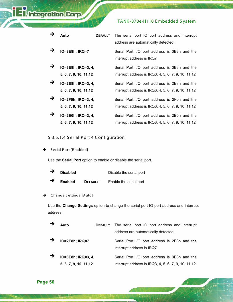
C hange S ettings [Auto]
Use the Change Settings option to change the serial port IO port address and interrupt
address.
Auto DEFAULT The serial port IO port address and interrupt
address are automatically detected.
IO=2E8h; IRQ=7 Serial Port I/O port address is 2E8h and the
interrupt address is IRQ7
IO=3E8h; IRQ=3, 4,
5, 6, 7, 9, 10, 11,12
Serial Port I/O port address is 3E8h and the
interrupt address is IRQ3, 4, 5, 6, 7, 9, 10, 11,12

TANK -870e-H110 E mbedded S ys tem
Page 57
IO=2E8h; IRQ=3, 4,
5, 6, 7, 9, 10, 11,12
Serial Port I/O port address is 2E8h and the
interrupt address is IRQ3, 4, 5, 6, 7, 9, 10, 11,12
IO=2F0h; IRQ=3, 4,
5, 6, 7, 9, 10, 11,12
Serial Port I/O port address is 2F0h and the
interrupt address is IRQ3, 4, 5, 6, 7, 9, 10, 11,12
IO=2E0h; IRQ=3, 4,
5, 6, 7, 9, 10, 11,12
Serial Port I/O port address is 2E0h and the
interrupt address is IRQ3, 4, 5, 6, 7, 9, 10, 11,12
5.3.5.1.5 S erial P ort 5 C onfiguration
S erial P ort [E nabled]
Use the Serial Port option to enable or disable the serial port.
Disabled Disable the serial port
Enabled DEFAULT Enable the serial port
C hange S ettings [Auto]
Use the Change Settings option to change the serial port IO port address and interrupt
address.
Auto DEFAULT The serial port IO port address and interrupt
address are automatically detected.
IO=2E0h; IRQ=7 Serial Port I/O port address is 2E0h and the
interrupt address is IRQ7
IO=3E8h; IRQ=3, 4,
5, 6, 7, 9, 10, 11,12
Serial Port I/O port address is 3E8h and the
interrupt address is IRQ3, 4, 5, 6, 7, 9, 10, 11,12
IO=2E8h; IRQ=3, 4,
5, 6, 7, 9, 10, 11,12
Serial Port I/O port address is 2E8h and the
interrupt address is IRQ3, 4, 5, 6, 7, 9, 10, 11,12
IO=2F0h; IRQ=3, 4,
5, 6, 7, 9, 10, 11,12
Serial Port I/O port address is 2F0h and the
interrupt address is IRQ3, 4, 5, 6, 7, 9, 10, 11,12
IO=2E0h; IRQ=3, 4,
5, 6, 7, 9, 10, 11,12
Serial Port I/O port address is 2E0h and the
interrupt address is IRQ3, 4, 5, 6, 7, 9, 10, 11,12

TANK -870e-H110 E mbedded S ys tem
Page 58
5.3.5.1.6 S erial P ort 6 C onfiguration
S erial P ort [E nabled]
Use the Serial Port option to enable or disable the serial port.
Disabled Disable the serial port
Enabled DEFAULT Enable the serial port
C hange S ettings [Auto]
Use the Change Settings option to change the serial port IO port address and interrupt
address.
Auto DEFAULT The serial port IO port address and interrupt
address are automatically detected.
IO=2F0h; IRQ=7 Serial Port I/O port address is 2F0h and the
interrupt address is IRQ7
IO=3E8h; IRQ=3, 4,
5, 6, 7, 9, 10, 11,12
Serial Port I/O port address is 3E8h and the
interrupt address is IRQ3, 4, 5, 6, 7, 9, 10, 11,12
IO=2E8h; IRQ=3, 4,
5, 6, 7, 9, 10, 11,12
Serial Port I/O port address is 2E8h and the
interrupt address is IRQ3, 4, 5, 6, 7, 9, 10, 11,12
IO=2F0h; IRQ=3, 4,
5, 6, 7, 9, 10, 11,12
Serial Port I/O port address is 2F0h and the
interrupt address is IRQ3, 4, 5, 6, 7, 9, 10, 11,12
IO=2E0h; IRQ=3, 4,
5, 6, 7, 9, 10, 11,12
Serial Port I/O port address is 2E0h and the
interrupt address is IRQ3, 4, 5, 6, 7, 9, 10, 11,12
5.3.6 R T C Wake S ettings
The RTC Wake Settings menu (BIOS Menu 9) configures RTC wake event.
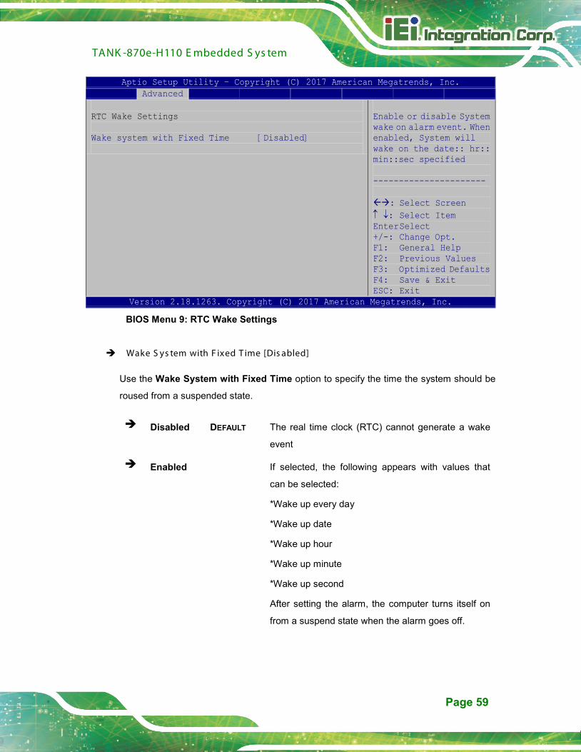
TANK -870e-H110 E mbedded S ys tem
Page 59
Aptio Setup Utility – Copyright (C) 2017 American Megatrends, Inc. Advanced
RTC Wake Settings Wake system with Fixed Time [Disabled]
Enable or disable System wake on alarm event. When enabled, System will wake on the date:: hr:: min::sec specified ---------------------- : Select Screen ↑ ↓: Select Item Enter Select +/-: Change Opt. F1: General Help F2: Previous Values F3: Optimized Defaults F4: Save & Exit ESC: Exit
Version 2.18.1263. Copyright (C) 2017 American Megatrends, Inc.
BIOS Menu 9: RTC Wake Settings
Wake S ys tem with F ixed T ime [Dis abled]
Use the Wake System with Fixed Time option to specify the time the system should be
roused from a suspended state.
Disabled DEFAULT The real time clock (RTC) cannot generate a wake
event
Enabled If selected, the following appears with values that
can be selected:
*Wake up every day
*Wake up date
*Wake up hour
*Wake up minute
*Wake up second
After setting the alarm, the computer turns itself on
from a suspend state when the alarm goes off.

TANK -870e-H110 E mbedded S ys tem
Page 60
5.3.7 S erial P ort C ons ole R edirec tion
The Serial Port Console Redirection menu (BIOS Menu 10) allows the console
redirection options to be configured. Console redirection allows users to maintain a
system remotely by re-directing keyboard input and text output through the serial port.
Aptio Setup Utility – Copyright (C) 2017 American Megatrends, Inc. Advanced
COM1 Console Redirection [Disabled]
> Console Redirection Settings COM2 Console Redirection [Disabled]
> Console Redirection Settings COM3 Console Redirection [Disabled]
> Console Redirection Settings COM4 Console Redirection [Disabled]
> Console Redirection Settings COM5 Console Redirection [Disabled]
> Console Redirection Settings COM6 Console Redirection [Disabled]
> Console Redirection Settings
Console Redirection Enable or Disable --------------------- : Select Screen ↑ ↓: Select Item Enter Select +/-: Change Opt. F1: General Help F2: Previous Values F3: Optimized Defaults F4: Save & Exit ESC: Exit
Version 2.18.1263. Copyright (C) 2017 American Megatrends, Inc.
BIOS Menu 10: Serial Port Console Redirection
C ons ole R edirec tion [Dis abled]
Use Console Redirection option to enable or disable the console redirection function.
Disabled DEFAULT Disabled the console redirection function
Enabled Enabled the console redirection function
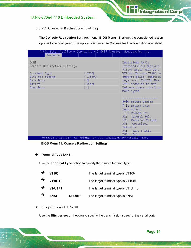
TANK -870e-H110 E mbedded S ys tem
Page 61
5.3.7.1 C ons ole R edirec tion S ettings
The Console Redirection Settings menu (BIOS Menu 11) allows the console redirection
options to be configured. The option is active when Console Redirection option is enabled.
Aptio Setup Utility – Copyright (C) 2017 American Megatrends, Inc. Advanced
COM1 Console Redirection Settings Terminal Type [ANSI] Bits per second [115200] Data Bits [8] Parity [None] Stop Bits [1]
Emulation: ANSI: Extended ASCII char set. VT100: ASCII char set. VT100+: Extends VT100 to support color, function keys, etc. VT-UTF8: Uses UTF8 encoding to map Unicode chars onto 1 or more bytes. --------------------- : Select Screen ↑ ↓: Select Item Enter Select +/-: Change Opt. F1: General Help F2: Previous Values F3: Optimized Defaults F4: Save & Exit ESC: Exit
Version 2.18.1263. Copyright (C) 2017 American Megatrends, Inc.
BIOS Menu 11: Console Redirection Settings
Terminal Type [ANS I]
Use the Terminal Type option to specify the remote terminal type..
VT100 The target terminal type is VT100
VT100+ The target terminal type is VT100+
VT-UTF8 The target terminal type is VT-UTF8
ANSI DEFAULT The target terminal type is ANSI
B its per s econd [115200]
Use the Bits per second option to specify the transmission speed of the serial port.

TANK -870e-H110 E mbedded S ys tem
Page 62
9600 The transmission speed is 9600
19200 The transmission speed is 19200
38400 The transmission speed is 38400
57600 The transmission speed is 57600
115200 DEFAULT The transmission speed is 115200
Data B its [8]
Use the Data Bits option to specify the number of data bits.
7 Sets the data bits at 7.
8 DEFAULT Sets the data bits at 8.
P arity [None]
Use the Parity option to specify the parity bit that can be sent with the data bits for
detecting the transmission errors.
None DEFAULT No parity bit is sent with the data bits.
Even The parity bit is 0 if the number of ones in the data
bits is even.
Odd The parity bit is 0 if the number of ones in the data
bits is odd.
Mark The parity bit is always 1. This option does not
provide error detection.
Space The parity bit is always 0. This option does not
provide error detection.
S top B its [1]
Use the Stop Bits option to specify the number of stop bits used to indicate the end of a
serial data packet. Communication with slow devices may require more than 1 stop bit.
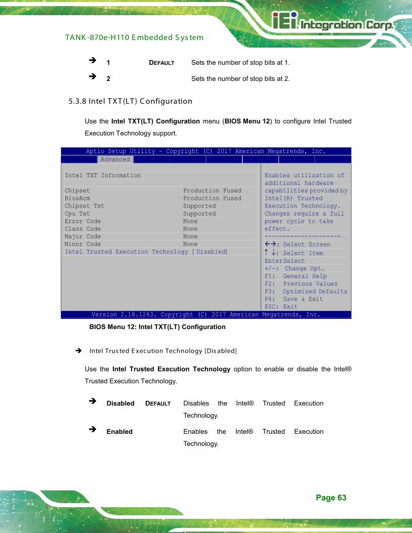
TANK -870e-H110 E mbedded S ys tem
Page 63
1 DEFAULT Sets the number of stop bits at 1.
2 Sets the number of stop bits at 2.
5.3.8 Intel T XT (LT ) C onfiguration
Use the Intel TXT(LT) Configuration menu (BIOS Menu 12) to configure Intel Trusted
Execution Technology support.
Aptio Setup Utility – Copyright (C) 2017 American Megatrends, Inc. Advanced
Intel TXT Information Chipset Production Fused BiosAcm Production Fused Chipset Txt Supported Cpu Txt Supported Error Code None Class Code None Major Code None Minor Code None Intel Trusted Execution Technology [Disabled]
Enables utilization of additional hardware capabilities provided by Intel(R) Trusted Execution Technology. Changes require a full power cycle to take effect. --------------------- : Select Screen ↑ ↓: Select Item Enter Select +/-: Change Opt. F1: General Help F2: Previous Values F3: Optimized Defaults F4: Save & Exit ESC: Exit
Version 2.18.1263. Copyright (C) 2017 American Megatrends, Inc.
BIOS Menu 12: Intel TXT(LT) Configuration
Intel Trus ted E xecution Tec hnology [Dis abled]
Use the Intel Trusted Execution Technology option to enable or disable the Intel®
Trusted Execution Technology.
Disabled DEFAULT Disables the Intel® Trusted Execution
Technology.
Enabled Enables the Intel® Trusted Execution
Technology.

TANK -870e-H110 E mbedded S ys tem
Page 64
5.3.9 US B C onfiguration
Use the USB Configuration menu (BIOS Menu 13) to read USB configuration
information and configure the USB settings.
Aptio Setup Utility – Copyright (C) 2017 American Megatrends, Inc. Advanced
USB Configuration USB Devices: 1 Keyboard Legacy USB Support [Enabled]
Enables Legacy USB support. AUTO option disables legacy support if no USB devices are connected. DISABLE option will keep USB devices available only for EFI applications. --------------------- : Select Screen ↑ ↓: Select Item Enter Select +/-: Change Opt. F1: General Help F2: Previous Values F3: Optimized Defaults F4: Save & Exit ESC: Exit
Version 2.18.1263. Copyright (C) 2017 American Megatrends, Inc.
BIOS Menu 13: USB Configuration
US B Devices
The USB Devices field lists the USB devices that are enabled on the system
L egac y US B S upport [E nabled]
Use the Legacy USB Support BIOS option to enable USB mouse and USB keyboard
support. Normally if this option is not enabled, any attached USB mouse or USB keyboard
does not become available until a USB compatible operating system is fully booted with all
USB drivers loaded. When this option is enabled, any attached USB mouse or USB
keyboard can control the system even when there is no USB driver loaded onto the
system.
Enabled DEFAULT Legacy USB support enabled
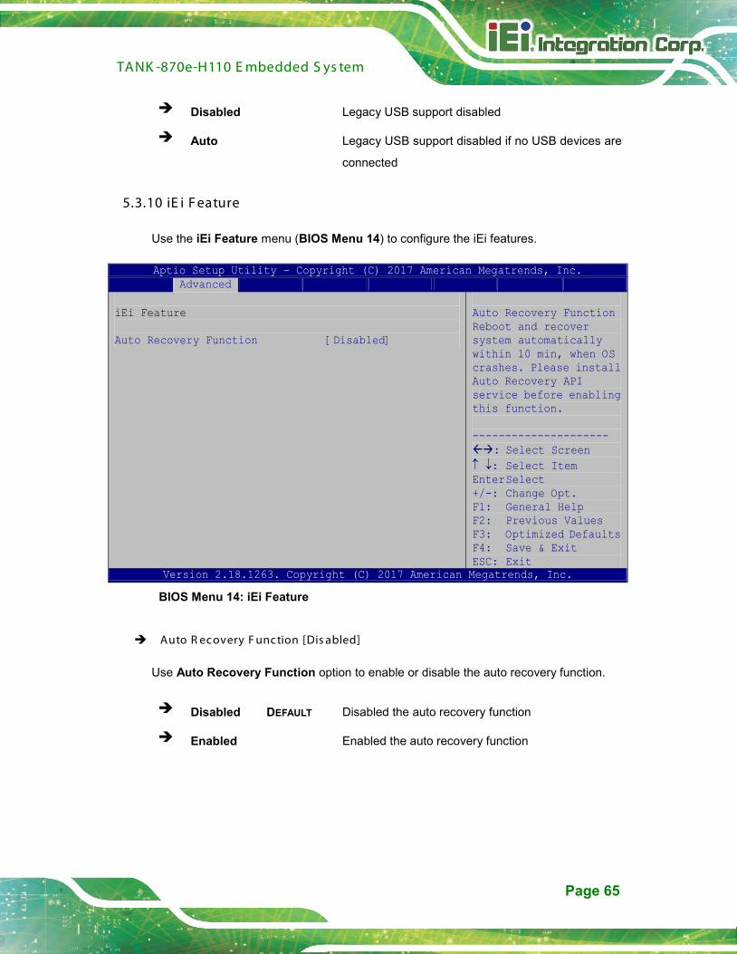
TANK -870e-H110 E mbedded S ys tem
Page 65
Disabled Legacy USB support disabled
Auto Legacy USB support disabled if no USB devices are
connected
5.3.10 iE i F eature
Use the iEi Feature menu (BIOS Menu 14) to configure the iEi features.
Aptio Setup Utility – Copyright (C) 2017 American Megatrends, Inc. Advanced
iEi Feature Auto Recovery Function [Disabled]
Auto Recovery Function Reboot and recover system automatically within 10 min, when OS crashes. Please install Auto Recovery API service before enabling this function. --------------------- : Select Screen ↑ ↓: Select Item Enter Select +/-: Change Opt. F1: General Help F2: Previous Values F3: Optimized Defaults F4: Save & Exit ESC: Exit
Version 2.18.1263. Copyright (C) 2017 American Megatrends, Inc.
BIOS Menu 14: iEi Feature
Auto R ec overy F unc tion [Dis abled]
Use Auto Recovery Function option to enable or disable the auto recovery function.
Disabled DEFAULT Disabled the auto recovery function
Enabled Enabled the auto recovery function

TANK -870e-H110 E mbedded S ys tem
Page 66
5.3.11 iWDD H/W Monitor
The iWDD H/W Monitor menu (BIOS Menu 15) shows the operating temperature, fan
speeds and system voltages.
Aptio Setup Utility – Copyright (C) 2017 American Megatrends, Inc. Advanced
PC Health Status CPU Temperature :+50 C SYS Temperature :+45 C CPU_FAN1 Speed :N/A +VCCCORE :+0.984 V +V5S :+5.160 V +V12S :+11.935 V +VDDQ :+1.208 V Tcc Activation Offset 0 > Smart Fan Mode Configuration
Offset from factory set Tcc activation temperature at which the Thermal Control Circuit must be activated. Tcc will be activated at: Tcc Activation Temp – Tcc Activation Offset. Tcc Activation Offset range is 0 to 63. --------------------- : Select Screen ↑ ↓: Select Item Enter Select +/-: Change Opt. F1: General Help F2: Previous Values F3: Optimized Defaults F4: Save & Exit ESC: Exit
Version 2.18.1263. Copyright (C) 2017 American Megatrends, Inc.
BIOS Menu 15: F81866 H/W Monitor
P C Health S tatus
The following system parameters and values are shown. The system parameters that are
monitored are:
System Temperatures:
o CPU Temperature
o System Temperature
Fan Speeds:
o CPU_Fan1 Speed
Voltages:
o +VCCCORE
o +V5S
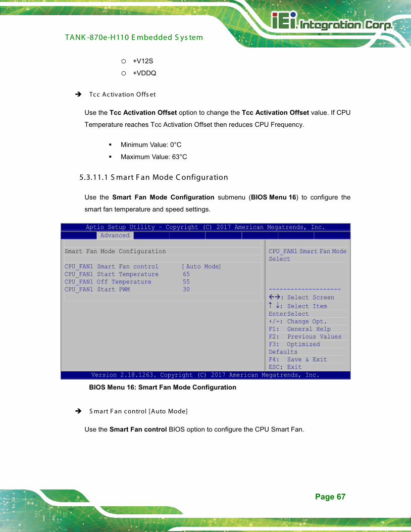
TANK -870e-H110 E mbedded S ys tem
Page 67
o +V12S
o +VDDQ
Tcc Activation Offs et
Use the Tcc Activation Offset option to change the Tcc Activation Offset value. If CPU
Temperature reaches Tcc Activation Offset then reduces CPU Frequency.
Minimum Value: 0°C
Maximum Value: 63°C
5.3.11.1 S mart F an Mode C onfiguration
Use the Smart Fan Mode Configuration submenu (BIOS Menu 16) to configure the
smart fan temperature and speed settings.
Aptio Setup Utility – Copyright (C) 2017 American Megatrends, Inc. Advanced
Smart Fan Mode Configuration CPU_FAN1 Smart Fan control [Auto Mode] CPU_FAN1 Start Temperature 65 CPU_FAN1 Off Temperature 55 CPU_FAN1 Start PWM 30
CPU_FAN1 Smart Fan Mode Select -------------------- : Select Screen ↑ ↓: Select Item Enter Select +/-: Change Opt. F1: General Help F2: Previous Values F3: Optimized Defaults F4: Save & Exit ESC: Exit
Version 2.18.1263. Copyright (C) 2017 American Megatrends, Inc.
BIOS Menu 16: Smart Fan Mode Configuration
S mart F an control [Auto Mode]
Use the Smart Fan control BIOS option to configure the CPU Smart Fan.
TANK -870e-H110 E mbedded S ys tem
Page 68
Auto Mode DEFAULT The fan adjusts its speed using these
settings:
CPU_FAN1 Start Temperature
CPU_FAN1 Off Temperature
CPU_FAN1 Start PWM
Manual Mode The fan spins at the speed set in the manual
setting
C P U_FAN1 S tart/Off Temperature
Use the + or – key to change the CPU_FAN1 Start/Off Temperature value. Enter a
decimal number between 1 and 100.
C P U_FAN1 s tart P W M
Use the + or – key to change the CPU_FAN1 start PWM value. Enter a decimal number
between 1 and 100.
5.4 C hips et
Use the Chipset menu (BIOS Menu 17) to access the PCH-IO and System Agent (SA)
configuration menus.
WAR NING !
Setting the wrong values for the Chipset BIOS selections in the Chipset
BIOS menu may cause the system to malfunction.

TANK -870e-H110 E mbedded S ys tem
Page 69
Aptio Setup Utility – Copyright (C) 2017 American Megatrends, Inc. Chipset
> System Agent (SA) Configuration > PCH-IO Configuration
System Agent (SA) Parameters --------------------- : Select Screen ↑ ↓: Select Item Enter Select +/-: Change Opt. F1: General Help F2: Previous Values F3: Optimized Defaults F4: Save & Exit ESC: Exit
Version 2.18.1263. Copyright (C) 2017 American Megatrends, Inc.
BIOS Menu 17: Chipset
5.4.1 S ys tem Agent (S A) C onfiguration
Use the System Agent (SA) Configuration menu (BIOS Menu 18) to configure the
System Agent (SA) parameters.
Aptio Setup Utility – Copyright (C) 2017 American Megatrends, Inc. Chipset
System Agent (SA) Configuration VT-d [Disabled] > Memory Configuration > Graphics Configuration > PEG Port Configuration
VT-d capability --------------------- : Select Screen ↑ ↓: Select Item Enter: Select +/-: Change Opt. F1: General Help F2: Previous Values F3: Optimized Defaults F4: Save & Exit ESC: Exit
Version 2.18.1263. Copyright (C) 2017 American Megatrends, Inc.
BIOS Menu 18: System Agent (SA) Configuration
VT-d [Dis abled]
Use the VT-d option to enable or disable VT-d support.
Disabled DEFAULT Disable VT-d support.
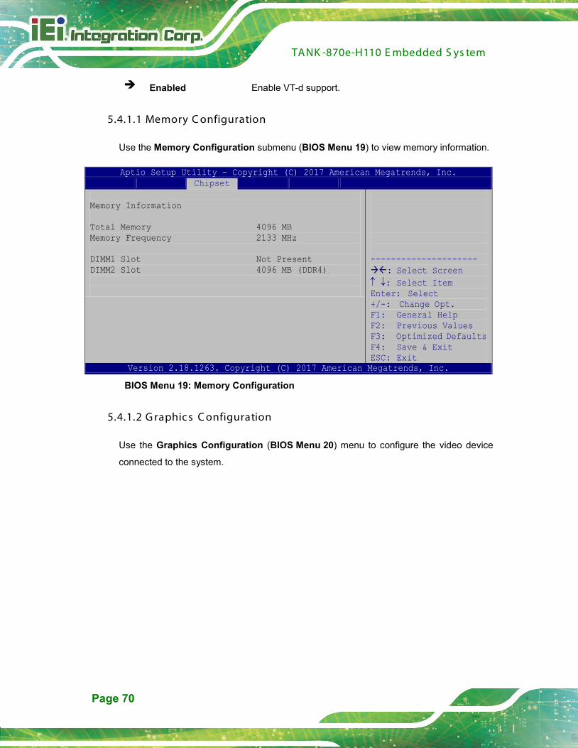
TANK -870e-H110 E mbedded S ys tem
Page 70
Enabled Enable VT-d support.
5.4.1.1 Memory C onfiguration
Use the Memory Configuration submenu (BIOS Menu 19) to view memory information.
Aptio Setup Utility – Copyright (C) 2017 American Megatrends, Inc. Chipset
Memory Information Total Memory 4096 MB Memory Frequency 2133 MHz DIMM1 Slot Not Present DIMM2 Slot 4096 MB (DDR4)
--------------------- : Select Screen ↑ ↓: Select Item Enter: Select +/-: Change Opt. F1: General Help F2: Previous Values F3: Optimized Defaults F4: Save & Exit ESC: Exit
Version 2.18.1263. Copyright (C) 2017 American Megatrends, Inc.
BIOS Menu 19: Memory Configuration
5.4.1.2 G raphic s C onfiguration
Use the Graphics Configuration (BIOS Menu 20) menu to configure the video device
connected to the system.
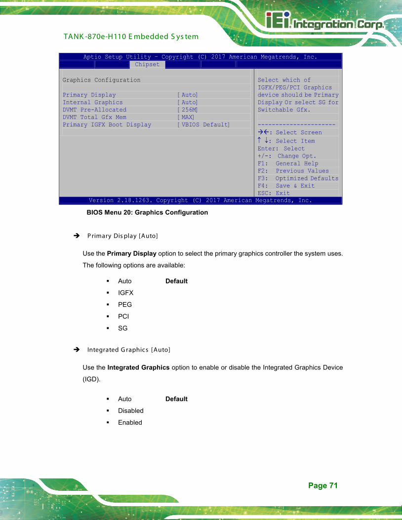
TANK -870e-H110 E mbedded S ys tem
Page 71
Aptio Setup Utility – Copyright (C) 2017 American Megatrends, Inc. Chipset
Graphics Configuration Primary Display [Auto] Internal Graphics [Auto] DVMT Pre-Allocated [256M] DVMT Total Gfx Mem [MAX] Primary IGFX Boot Display [VBIOS Default]
Select which of IGFX/PEG/PCI Graphics device should be Primary Display Or select SG for Switchable Gfx. ---------------------- : Select Screen ↑ ↓: Select Item Enter: Select +/-: Change Opt. F1: General Help F2: Previous Values F3: Optimized Defaults F4: Save & Exit ESC: Exit
Version 2.18.1263. Copyright (C) 2017 American Megatrends, Inc.
BIOS Menu 20: Graphics Configuration
P rimary Dis play [Auto]
Use the Primary Display option to select the primary graphics controller the system uses.
The following options are available:
Auto Default
IGFX
PEG
PCI
SG
Integrated G raphics [Auto]
Use the Integrated Graphics option to enable or disable the Integrated Graphics Device
(IGD).
Auto Default
Disabled
Enabled

TANK -870e-H110 E mbedded S ys tem
Page 72
DVMT P re-Allocated [256M]
Use the DVMT Pre-Allocated option to set the amount of system memory allocated to the
integrated graphics processor when the system boots. The system memory allocated can
then only be used as graphics memory, and is no longer available to applications or the
operating system. Configuration options are listed below:
128M
256M Default
512M
DVMT Total G fx Mem [MAX]
Use the DVMT Total Gfx Mem option to select DVMT5.0 total graphic memory size used
by the internal graphic device. The following options are available:
256M
128M
MAX Default
P rimary IG F X B oot Dis play [VB IO S Default]
Use the Primary IGFX Boot Display option to select the display device used by the
system when it boots. Configuration options are listed below.
VBIOS Default DEFAULT
VGA
HDMI
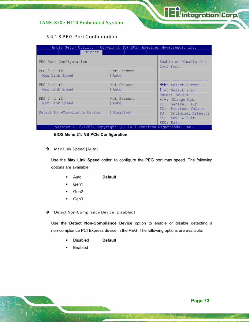
TANK -870e-H110 E mbedded S ys tem
Page 73
5.4.1.3 P E G P ort C onfiguration
Aptio Setup Utility – Copyright (C) 2017 American Megatrends, Inc. Chipset
PEG Port Configuration PEG 0 :1 :0 Not Present Max Link Speed [Auto]
PEG 0 :1 :1 Not Present Max Link Speed [Auto]
PEG 0 :1 :2 Not Present Max Link Speed [Auto]
Detect Non-Compliance Device [Disabled]
Enable or Disable the Root Port ---------------------- : Select Screen ↑ ↓: Select Item Enter: Select +/-: Change Opt. F1: General Help F2: Previous Values F3: Optimized Defaults F4: Save & Exit ESC: Exit
Version 2.18.1263. Copyright (C) 2017 American Megatrends, Inc.
BIOS Menu 21: NB PCIe Configuration
Max L ink S peed [Auto]
Use the Max Link Speed option to configure the PEG port max speed. The following
options are available:
Auto Default
Gen1
Gen2
Gen3
Detect Non-C omplianc e Device [Dis abled]
Use the Detect Non-Compliance Device option to enable or disable detecting a
non-compliance PCI Express device in the PEG. The following options are available:
Disabled Default
Enabled
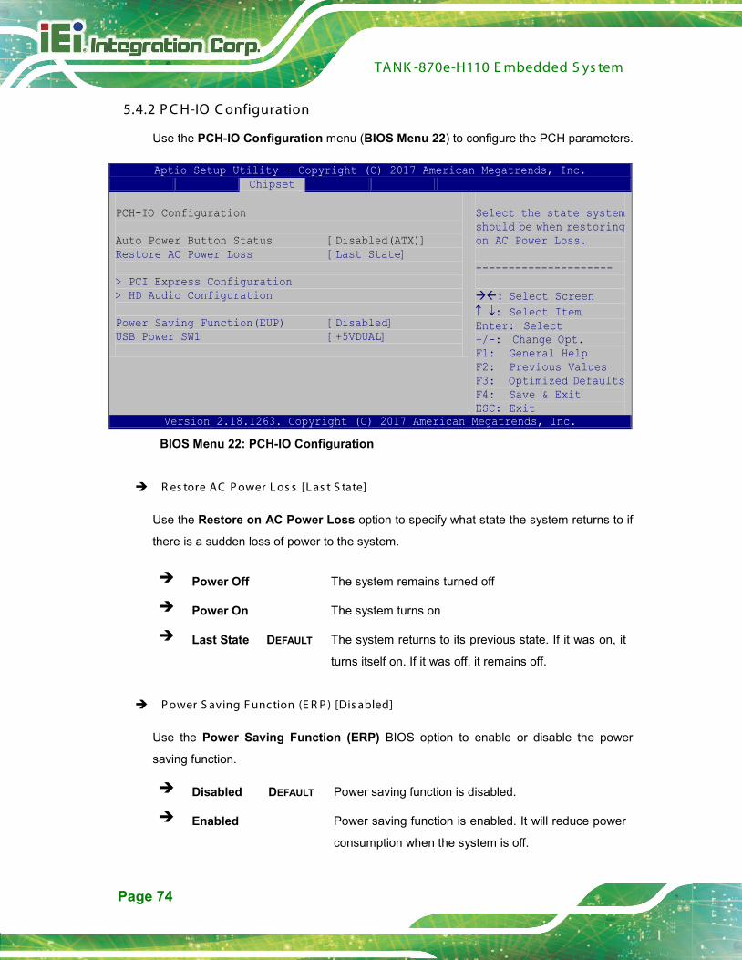
TANK -870e-H110 E mbedded S ys tem
Page 74
5.4.2 P C H-IO C onfiguration
Use the PCH-IO Configuration menu (BIOS Menu 22) to configure the PCH parameters.
Aptio Setup Utility – Copyright (C) 2017 American Megatrends, Inc. Chipset
PCH-IO Configuration Auto Power Button Status [Disabled(ATX)] Restore AC Power Loss [Last State] > PCI Express Configuration > HD Audio Configuration Power Saving Function(EUP) [Disabled] USB Power SW1 [+5VDUAL]
Select the state system should be when restoring on AC Power Loss. --------------------- : Select Screen ↑ ↓: Select Item Enter: Select +/-: Change Opt. F1: General Help F2: Previous Values F3: Optimized Defaults F4: Save & Exit ESC: Exit
Version 2.18.1263. Copyright (C) 2017 American Megatrends, Inc.
BIOS Menu 22: PCH-IO Configuration
R es tore AC P ower L os s [L as t S tate]
Use the Restore on AC Power Loss option to specify what state the system returns to if
there is a sudden loss of power to the system.
Power Off The system remains turned off
Power On The system turns on
Last State DEFAULT The system returns to its previous state. If it was on, it
turns itself on. If it was off, it remains off.
P ower S aving F unc tion (E R P ) [Dis abled]
Use the Power Saving Function (ERP) BIOS option to enable or disable the power
saving function.
Disabled DEFAULT Power saving function is disabled.
Enabled Power saving function is enabled. It will reduce power
consumption when the system is off.

TANK -870e-H110 E mbedded S ys tem
Page 75
US B P ower S W1 [+5V DUAL ]
Use the USB Power SW1 BIOS option to configure the USB power source for the
corresponding USB connectors.
+5V Sets the USB power source to +5V
+5VDUAL DEFAULT Sets the USB power source to +5V dual
5.4.2.1 P C I E xpres s C onfiguration
Use the PCI Express Configuration menu (BIOS Menu 23) to select the support type of
the PCIe Mini slot.
Aptio Setup Utility – Copyright (C) 2017 American Megatrends, Inc. Chipset
PCI Express Configuration > M_PCIE1 > ITE8892 > PCIEx16 > M_PCIE2
PCI Express Root Port 6 Settings. ---------------------- : Select Screen ↑ ↓: Select Item Enter: Select +/-: Change Opt. F1: General Help F2: Previous Values F3: Optimized Defaults F4: Save & Exit ESC: Exit
Version 2.18.1263. Copyright (C) 2017 American Megatrends, Inc.
BIOS Menu 23: PCI Express Configuration
The M_PCIE1, ITE8892, PCIEx16 and M_PCIE2 submenus all contain the following
options:
P C Ie S peed
Use PCIe Speed option to select the speed type of the PCIe Mini slot. The following
options are available:
Auto Default
Gen1
Gen2

TANK -870e-H110 E mbedded S ys tem
Page 76
Gen3
Detect Non-C omplianc e Device [Dis abled]
Use the Detect Non-Compliance Device option to enable or disable the “detect
no-compliance PCIe device” function.
Disabled DEFAULT Detect no-compliance PCIe device function is disabled
Enabled Detect no-compliance PCIe device function is enabled. If
will take more time at POST if it is enabled.
5.4.2.2 HD Audio C onfiguration
Use the HD Audio Configuration submenu (BIOS Menu 24) to configure the High
Definition Audio codec.
Aptio Setup Utility – Copyright (C) 2017 American Megatrends, Inc. Chipset
HD Audio Configuration HD Audio [Auto]
Control Detection of the Azalia device. Disable = Azalia will be unconditionally disabled Enabled = Azalia will be unconditionally Enabled. --------------------- : Select Screen ↑ ↓: Select Item Enter Select + - Change Opt. F1 General Help F2 Previous Values F3 Optimized Defaults F4 Save & Exit ESC Exit
Version 2.18.1263. Copyright (C) 2017 American Megatrends, Inc.
BIOS Menu 24: HD Audio Configuration
HD Audio [Auto]
Use the HD Audio BIOS option to enable or disable the High Definition Audio controller.

TANK -870e-H110 E mbedded S ys tem
Page 77
Disabled The High Definition Audio controller is disabled.
Enabled The High Definition Audio controller is enabled.
Auto DEFAULT The onboard High Definition Audio controller
automatically detected and enabled.
5.5 S ec urity
Use the Security menu (BIOS Menu 25) to set system and user passwords.
Aptio Setup Utility – Copyright (C) 2017 American Megatrends, Inc. Security
Password Description If ONLY the Administrator’s password is set, then this only limits access to Setup and is only asked for when entering Setup. If ONLY the User’s password is set, then this is a power on password and must be entered to boot or enter Setup. In Setup the User will have Administrator rights. The password length must be: Minimum length 3 Maximum length 20 Administrator Password User Password
Set Administrator Password --------------------- : Select Screen ↑ ↓: Select Item Enter Select +/-: Change Opt. F1: General Help F2: Previous Values F3: Optimized Defaults F4: Save & Exit ESC: Exit
Version 2.18.1263. Copyright (C) 2017 American Megatrends, Inc.
BIOS Menu 25: Security
Adminis trator P as s word
Use the Administrator Password to set or change an administrator password.
Us er P as s word
Use the User Password to set or change a user password.
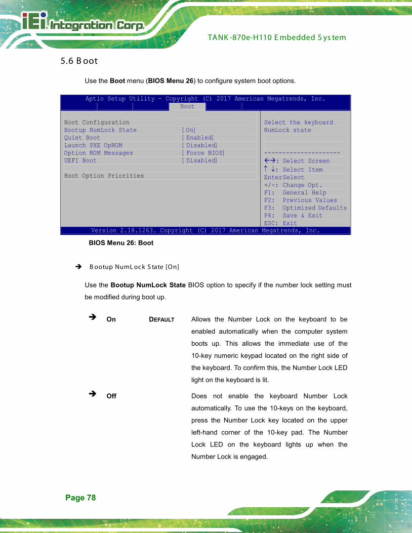
TANK -870e-H110 E mbedded S ys tem
Page 78
5.6 B oot
Use the Boot menu (BIOS Menu 26) to configure system boot options.
Aptio Setup Utility – Copyright (C) 2017 American Megatrends, Inc. Boot
Boot Configuration Bootup NumLock State [On] Quiet Boot [Enabled] Launch PXE OpROM [Disabled] Option ROM Messages [Force BIOS] UEFI Boot [Disabled] Boot Option Priorities
Select the keyboard NumLock state --------------------- : Select Screen ↑ ↓: Select Item Enter Select +/-: Change Opt. F1: General Help F2: Previous Values F3: Optimized Defaults F4: Save & Exit ESC: Exit
Version 2.18.1263. Copyright (C) 2017 American Megatrends, Inc.
BIOS Menu 26: Boot
B ootup NumL oc k S tate [On]
Use the Bootup NumLock State BIOS option to specify if the number lock setting must
be modified during boot up.
On DEFAULT Allows the Number Lock on the keyboard to be
enabled automatically when the computer system
boots up. This allows the immediate use of the
10-key numeric keypad located on the right side of
the keyboard. To confirm this, the Number Lock LED
light on the keyboard is lit.
Off Does not enable the keyboard Number Lock
automatically. To use the 10-keys on the keyboard,
press the Number Lock key located on the upper
left-hand corner of the 10-key pad. The Number
Lock LED on the keyboard lights up when the
Number Lock is engaged.
TANK -870e-H110 E mbedded S ys tem
Page 79
Quiet B oot [E nabled]
Use the Quiet Boot BIOS option to select the screen display when the system boots.
Disabled Normal POST messages displayed
Enabled DEFAULT OEM Logo displayed instead of POST messages
L aunch P XE OpR OM [Dis abled]
Use the Launch PXE OpROM option to enable or disable boot option for legacy network
devices.
Disabled DEFAULT Ignore all PXE Option ROMs
Enabled Load PXE Option ROMs.
Option R OM Mes s ages [F orce B IOS ]
Use the Option ROM Messages option to set the Option ROM display mode.
Force BIOS DEFAUL
T
Sets display mode to force BIOS.
Keep Current Sets display mode to current.
UE F I B oot [Dis abled]
Use the UEFI Boot option to enable or disable to boot from the UEFI devices.
Enabled Boot from UEFI devices is enabled.
Disabled DEFAULT Boot from UEFI devices is disabled.

TANK -870e-H110 E mbedded S ys tem
Page 80
5.7 S ave & E xit
Use the Save & Exit menu (BIOS Menu 27) to load default BIOS values, optimal failsafe
values and to save configuration changes.
Aptio Setup Utility – Copyright (C) 2017 American Megatrends, Inc. Save & Exit
Save Changes and Reset Discard Changes and Reset
Restore Defaults Save as User Defaults Restore User Defaults
Exit the system after saving the changes. --------------------- : Select Screen ↑ ↓: Select Item Enter Select +/-: Change Opt. F1: General Help F2: Previous Values F3: Optimized Defaults F4: Save & Exit ESC: Exit
Version 2.18.1263. Copyright (C) 2017 American Megatrends, Inc.
BIOS Menu 27:Exit
S ave C hanges and R es et
Use the Save Changes and Reset option to save the changes made to the BIOS options
and reset the system.
Dis card C hanges and R es et
Use the Discard Changes and Reset option to exit the system without saving the
changes made to the BIOS configuration setup program.
R es tore Defaults
Use the Restore Defaults option to load the optimal default values for each of the
parameters on the Setup menus. F3 key can be used for this operation.
TANK -870e-H110 E mbedded S ys tem
Page 81
S ave as Us er Defaults
Use the Save as User Defaults option to save the changes done so far as user defaults.
R es tore Us er Defaults
Use the Restore User Defaults option to restore the user defaults to all the setup options.

TANK -870e-H110 E mbedded S ys tem
Page 82
Appendix
A
A R egulatory C omplianc e
TANK -870e-H110 E mbedded S ys tem
Page 83
DE C L AR AT ION OF C ONF OR MIT Y
This equipment is in conformity with the following EU directives:
EMC Directive (2004/108/EC, 2014/30/EU)
Low-Voltage Directive (2006/95/EC, 2014/35/EU)
RoHS II Directive (2011/65/EU, 2015/863/EU)
If the user modifies and/or install other devices in the equipment, the CE conformity
declaration may no longer apply.
If this equipment has telecommunications functionality, it also complies with the
requirements of the Radio Equipment Directive 2014/53/EU.
English
IEI Integration Corp declares that this equipment is in compliance wit
the essential requirements and other relevant provisions of Directive
2014/53/EU.
Български [Bulgarian]
IEI Integration Corp. декларира, че този оборудване е в
съответствие със съществените изисквания и другите приложим
правила на Директива 2014/53/EU.
Česky [Czech]
IEI Integration Corp tímto prohlašuje, že tento zařízení je ve shodě s
základními požadavky a dalšími příslušnými ustanoveními směrnice
2014/53/EU.
Dansk [Danish]
IEI Integration Corp erklærer herved, at følgende udstyr overholder
de væsentlige krav og øvrige relevante krav i direktiv 2014/53/EU.

TANK -870e-H110 E mbedded S ys tem
Page 84
Deutsch [German]
IEI Integration Corp, erklärt dieses Gerät entspricht den
grundlegenden Anforderungen und den weiteren entsprechenden
Vorgaben der Richtlinie 2014/53/EU.
Eesti [Estonian]
IEI Integration Corp deklareerib seadme seadme vastavust direktiivi
2014/53/EÜ põhinõuetele ja nimetatud direktiivist tulenevatele teistele
asjakohastele sätetele.
Español [Spanish]
IEI Integration Corp declara que el equipo cumple con los requisitos
esenciales y cualesquiera otras disposiciones aplicables o exigibles
de la Directiva 2014/53/EU.
Ελληνική [Greek]
IEI Integration Corp ΔΗΛΩΝΕΙ ΟΤΙ ΕΞΟΠΛΙΣΜΟΣ
ΣΥΜΜΟΡΦΩΝΕΤΑΙ ΠΡΟΣ ΤΙΣ ΟΥΣΙΩΔΕΙΣ ΑΠΑΙΤΗΣΕΙΣ ΚΑΙ ΤΙΣ
ΛΟΙΠΕΣ ΣΧΕΤΙΚΕΣ ΔΙΑΤΑΞΕΙΣ ΤΗΣ ΟΔΗΓΙΑΣ 2014/53/EU.
Français [French]
IEI Integration Corp déclare que l'appareil est conforme aux
exigences essentielles et aux autres dispositions pertinentes de la
directive 2014/53/EU.
Italiano [Italian]
IEI Integration Corp dichiara che questo apparecchio è conforme ai
requisiti essenziali ed alle altre disposizioni pertinenti stabilite dalla
direttiva 2014/53/EU.
Latviski [Latvian]
IEI Integration Corp deklarē, ka iekārta atbilst būtiskajām prasībām un
citiem ar to saistītajiem noteikumiem Direktīvas 2014/53/EU.
TANK -870e-H110 E mbedded S ys tem
Page 85
Lietuvių [Lithuanian]
IEI Integration Corp deklaruoja, kad šis įranga atitinka esminius
reikalavimus ir kitas 2014/53/EU Direktyvos nuostatas.
Nederlands [Dutch]
IEI Integration Corp dat het toestel toestel in overeenstemming is met
de essentiële eisen en de andere relevante bepalingen van richtlijn
2014/53/EU.
Malti [Maltese]
IEI Integration Corp jiddikjara li dan prodott jikkonforma mal-ħtiġijiet
essenzjali u ma provvedimenti oħrajn relevanti li hemm fid-Dirrettiva
2014/53/EU.
Magyar [Hungarian]
IEI Integration Corp nyilatkozom, hogy a berendezés megfelel a
vonatkozó alapvetõ követelményeknek és az 2014/53/EU irányelv
egyéb elõírásainak.
Polski [Polish]
IEI Integration Corp oświadcza, że wyrobu jest zgodny z
zasadniczymi wymogami oraz pozostałymi stosownymi
postanowieniami Dyrektywy 2014/53/EU.
Português [Portuguese]
IEI Integration Corp declara que este equipamento está conforme
com os requisitos essenciais e outras disposições da Directiva
2014/53/EU.
Româna [Romanian]
IEI Integration Corp declară că acest echipament este in conformitate
cu cerinţele esenţiale şi cu celelalte prevederi relevante ale Directivei
2014/53/EU.

TANK -870e-H110 E mbedded S ys tem
Page 86
Slovensko [Slovenian]
IEI Integration Corp izjavlja, da je ta opreme v skladu z bistvenimi
zahtevami in ostalimi relevantnimi določili direktive 2014/53/EU.
Slovensky [Slovak]
IEI Integration Corp týmto vyhlasuje, že zariadenia spĺňa základné
požiadavky a všetky príslušné ustanovenia Smernice 2014/53/EU.
Suomi [Finnish]
IEI Integration Corp vakuuttaa täten että laitteet on direktiivin
2014/53/EU oleellisten vaatimusten ja sitä koskevien direktiivin
muiden ehtojen mukainen.
Svenska [Swedish]
IEI Integration Corp förklarar att denna utrustningstyp står I
överensstämmelse med de väsentliga egenskapskrav och övriga
relevanta bestämmelser som framgår av direktiv 2014/53/EU.
F C C WAR NING
This equipment complies with Part 15 of the FCC Rules. Operation is subject to the
following two conditions:
This device may not cause harmful interference, and
This device must accept any interference received, including interference
that may cause undesired operation.
This equipment has been tested and found to comply with the limits for a Class A digital
device, pursuant to part 15 of the FCC Rules. These limits are designed to provide
reasonable protection against harmful interference when the equipment is operated in a
commercial environment. This equipment generates, uses, and can radiate radio
frequency energy and, if not installed and used in accordance with the instruction
manual, may cause harmful interference to radio communications. Operation of this
equipment in a residential area is likely to cause harmful interference in which case the
user will be required to correct the interference at his own expense.

TANK -870e-H110 E mbedded S ys tem
Page 87
Federal Communication Commission Interference Statement
This equipment has been assembled with components that comply with the limits for a
Class B digital device, pursuant to Part 15 of the FCC Rules. These limits are designed
to provide reasonable protection against harmful interference in a residential installation.
This equipment generates, uses and can radiate radio frequency energy and, if not
installed and used in accordance with the instructions, may cause harmful interference
to radio communications. However, there is no guarantee that interference will not occur
in a particular installation. If this equipment does cause harmful interference to radio or
television reception, which can be determined by turning the equipment off and on, the
user is encouraged to try to correct the interference by one of the following measures:
Reorient or relocate the receiving antenna.
Increase the separation between the equipment and receiver.
Connect the equipment into an outlet on a circuit different from that to which
the receiver is connected.
Consult the dealer or an experienced radio/TV technician for help.
TANK -870e-H110 E mbedded S ys tem
Page 88
Appendix
B
B B IOS Options
TANK -870e-H110 E mbedded S ys tem
Page 89
Below is a list of BIOS configuration options in the BIOS chapter.
System Date [xx/xx/xx] ........................................................................................................45
System Time [xx:xx:xx] .......................................................................................................45
Intel (VMX) Virtualization Technology [Disabled] .............................................................48
Active Processor Cores [All] ..............................................................................................48
EIST [Enabled] ......................................................................................................................48
C states [Disabled] ...............................................................................................................48
Security Device Support [Disable] .....................................................................................49
ACPI Sleep State [S3 (Suspend to RAM)] ..........................................................................50
SATA Controller(s) [Enabled] .............................................................................................51
SATA Mode Selection [AHCI] ..............................................................................................51
Hot Plug [Disabled] ..............................................................................................................51
Serial Port [Enabled] ............................................................................................................53
Change Settings [Auto] .......................................................................................................53
Device Mode [RS232] ...........................................................................................................54
Serial Port [Enabled] ............................................................................................................54
Change Settings [Auto] .......................................................................................................54
Device Mode [RS232] ...........................................................................................................55
Serial Port [Enabled] ............................................................................................................55
Change Settings [Auto] .......................................................................................................55
Serial Port [Enabled] ............................................................................................................56
Change Settings [Auto] .......................................................................................................56
Serial Port [Enabled] ............................................................................................................57
Change Settings [Auto] .......................................................................................................57
Serial Port [Enabled] ............................................................................................................58
Change Settings [Auto] .......................................................................................................58
Wake System with Fixed Time [Disabled] .........................................................................59
Console Redirection [Disabled] ..........................................................................................60
Terminal Type [ANSI] ...........................................................................................................61
Bits per second [115200] .....................................................................................................61
Data Bits [8] ..........................................................................................................................62
Parity [None] .........................................................................................................................62
Stop Bits [1] ..........................................................................................................................62
Intel Trusted Execution Technology [Disabled] ...............................................................63

TANK -870e-H110 E mbedded S ys tem
Page 90
USB Devices .........................................................................................................................64
Legacy USB Support [Enabled] ..........................................................................................64
Auto Recovery Function [Disabled] ...................................................................................65
PC Health Status ..................................................................................................................66
Tcc Activation Offset ...........................................................................................................67
Smart Fan control [Auto Mode] ..........................................................................................67
CPU_FAN1 Start/Off Temperature ......................................................................................68
CPU_FAN1 start PWM .........................................................................................................68
VT-d [Disabled] .....................................................................................................................69
Primary Display [Auto] ........................................................................................................71
Integrated Graphics [Auto] .................................................................................................71
DVMT Pre-Allocated [256M] ................................................................................................72
DVMT Total Gfx Mem [MAX] ................................................................................................72
Primary IGFX Boot Display [VBIOS Default] .....................................................................72
Max Link Speed [Auto] ........................................................................................................73
Detect Non-Compliance Device [Disabled] .......................................................................73
Restore AC Power Loss [Last State] .................................................................................74
Power Saving Function (ERP) [Disabled] ..........................................................................74
USB Power SW1 [+5V DUAL] ..............................................................................................75
PCIe Speed ...........................................................................................................................75
Detect Non-Compliance Device [Disabled] .......................................................................76
HD Audio [Auto] ...................................................................................................................76
Administrator Password .....................................................................................................77
User Password .....................................................................................................................77
Bootup NumLock State [On] ...............................................................................................78
Quiet Boot [Enabled] ...........................................................................................................79
Launch PXE OpROM [Disabled] .........................................................................................79
Option ROM Messages [Force BIOS] .................................................................................79
UEFI Boot [Disabled] ...........................................................................................................79
Save Changes and Reset ....................................................................................................80
Discard Changes and Reset ...............................................................................................80
Restore Defaults ..................................................................................................................80
Save as User Defaults .........................................................................................................81
Restore User Defaults .........................................................................................................81

TANK -870e-H110 E mbedded S ys tem
Page 91
Appendix
C
C T erminology

TANK -870e-H110 E mbedded S ys tem
Page 92
AC ’97 Audio Codec 97 (AC’97) refers to a codec standard developed by Intel®
in 1997.
AC P I Advanced Configuration and Power Interface (ACPI) is an OS-directed
configuration, power management, and thermal management interface.
AHC I Advanced Host Controller Interface (AHCI) is a SATA Host controller
register-level interface.
AT A The Advanced Technology Attachment (ATA) interface connects storage
devices including hard disks and CD-ROM drives to a computer.
AR MD An ATAPI Removable Media Device (ARMD) is any ATAPI device that
supports removable media, besides CD and DVD drives.
AS K IR Amplitude Shift Keyed Infrared (ASKIR) is a form of modulation that
represents a digital signal by varying the amplitude (“volume”) of the
signal. A low amplitude signal represents a binary 0, while a high
amplitude signal represents a binary 1.
B IOS The Basic Input/Output System (BIOS) is firmware that is first run when
the computer is turned on and can be configured by the end user
C ODE C The Compressor-Decompressor (CODEC) encodes and decodes digital
audio data on the system.
C ompactF las h® CompactFlash® is a solid-state storage device. CompactFlash® devices
use flash memory in a standard size enclosure. Type II is thicker than
Type I, but a Type II slot can support both types.
C MOS Complimentary metal-oxide-conductor is an integrated circuit used in
chips like static RAM and microprocessors.
C OM COM refers to serial ports. Serial ports offer serial communication to
expansion devices. The serial port on a personal computer is usually a
male D-sub 9 connector.
DAC The Digital-to-Analog Converter (DAC) converts digital signals to analog
signals.
DDR Double Data Rate refers to a data bus transferring data on both the rising
and falling edges of the clock signal.
TANK -870e-H110 E mbedded S ys tem
Page 93
DMA Direct Memory Access (DMA) enables some peripheral devices to
bypass the system processor and communicate directly with the system
memory.
DIMM Dual Inline Memory Modules are a type of RAM that offer a 64-bit data
bus and have separate electrical contacts on each side of the module.
DIO The digital inputs and digital outputs are general control signals that
control the on/off circuit of external devices or TTL devices. Data can be
read or written to the selected address to enable the DIO functions.
E HC I The Enhanced Host Controller Interface (EHCI) specification is a
register-level interface description for USB 2.0 Host Controllers.
E IDE Enhanced IDE (EIDE) is a newer IDE interface standard that has data
transfer rates between 4.0 MBps and 16.6 MBps.
E IS T Enhanced Intel® SpeedStep Technology (EIST) allows users to modify
the power consumption levels and processor performance through
application software. The application software changes the bus-to-core
frequency ratio and the processor core voltage.
F S B The Front Side Bus (FSB) is the bi-directional communication channel
between the processor and the Northbridge chipset.
G bE Gigabit Ethernet (GbE) is an Ethernet version that transfers data at 1.0
Gbps and complies with the IEEE 802.3-2005 standard.
G P IO General purpose input
HDD Hard disk drive (HDD) is a type of magnetic, non-volatile computer
storage device that stores digitally encoded data.
IC H The Input/Ouput Controll Hub (ICH) is an Intel® Southbridge chipset.
IrDA Infrared Data Association (IrDA) specify infrared data transmission
protocols used to enable electronic devices to wirelessly communicate
with each other.
L 1 C ache The Level 1 Cache (L1 Cache) is a small memory cache built into the
system processor.
L 2 C ache The Level 2 Cache (L2 Cache) is an external processor memory cache.

TANK -870e-H110 E mbedded S ys tem
Page 94
L C D Liquid crystal display (LCD) is a flat, low-power display device that
consists of two polarizing plates with a liquid crystal panel in between.
L VDS Low-voltage differential signaling (LVDS) is a dual-wire, high-speed
differential electrical signaling system commonly used to connect LCD
displays to a computer.
P OS T The Power-on Self Test (POST) is the pre-boot actions the system
performs when the system is turned-on.
R AM Random Access Memory (RAM) is volatile memory that loses data when
power is lost. RAM has very fast data transfer rates compared to other
storage like hard drives.
S AT A Serial ATA (SATA) is a serial communications bus designed for data
transfers between storage devices and the computer chipsets. The SATA
bus has transfer speeds up to 1.5 Gbps and the SATA II bus has data
transfer speeds of up to 3.0 Gbps.
S .M.A.R .T Self Monitoring Analysis and Reporting Technology (S.M.A.R.T) refers to
automatic status checking technology implemented on hard disk drives.
UAR T Universal Asynchronous Receiver-transmitter (UART) is responsible for
asynchronous communications on the system and manages the system’s
serial communication (COM) ports.
UHC I The Universal Host Controller Interface (UHCI) specification is a
register-level interface description for USB 1.1 Host Controllers.
US B The Universal Serial Bus (USB) is an external bus standard for
interfacing devices. USB 1.1 supports 12Mbps data transfer rates and
USB 2.0 supports 480Mbps data transfer rates.
VG A The Video Graphics Array (VGA) is a graphics display system developed
by IBM.

TANK -870e-H110 E mbedded S ys tem
Page 95
Appendix
D
D S afety P rec autions

TANK -870e-H110 E mbedded S ys tem
Page 96
D.1 S afety P rec autions
WAR NING :
The precautions outlined in this appendix should be strictly followed.
Failure to follow these precautions may result in permanent damage to
the TANK-870e-H110.
Please follow the safety precautions outlined in the sections that follow:
D.1.1 G eneral S afety P rec autions
Please ensure the following safety precautions are adhered to at all times.
Make sure the power is turned off and the power cord is disconnected
when moving, installing or modifying the system.
Do not apply voltage levels that exceed the specified voltage range.
Doing so may cause fire and/or an electrical shock.
Electric shocks can occur if opened while still powered on.
Do not drop or insert any objects into the ventilation openings.
If considerable amounts of dust, water, or fluids enter the system, turn
off the power supply immediately, unplug the power cord, and contact the
system vendor.
DO NOT:
o Drop the system against a hard surface.
o In a site where the ambient temperature exceeds the rated temperature

TANK -870e-H110 E mbedded S ys tem
Page 97
D.1.2 Anti-s tatic P recautions
WAR NING :
Failure to take ESD precautions during the installation of the
TANK-870e-H110 may result in permanent damage to the
TANK-870e-H110 and severe injury to the user.
Electrostatic discharge (ESD) can cause serious damage to electronic components,
including the TANK-870e-H110. Dry climates are especially susceptible to ESD. It is
therefore critical that whenever the TANK-870e-H110 is opened and any of the electrical
components are handled, the following anti-static precautions are strictly adhered to.
Wear an anti-static wristband: Wearing a simple anti-static wristband can
help to prevent ESD from damaging any electrical component.
Self-grounding: Before handling any electrical component, touch any
grounded conducting material. During the time the electrical component is
handled, frequently touch any conducting materials that are connected to the
ground.
Use an anti-static pad: When configuring or working with an electrical
component, place it on an antic-static pad. This reduces the possibility of ESD
damage.
Only handle the edges of the electrical component: When handling the
electrical component, hold the electrical component by its edges.

TANK -870e-H110 E mbedded S ys tem
Page 98
D.1.3 P roduc t Dis pos al
CAUTION:
Risk of explosion if battery is replaced by and incorrect type. Only
certified engineers should replace the on-board battery.
Dispose of used batteries according to instructions and local
regulations.
Outside the European Union–If you wish to dispose of used electrical and
electronic products outside the European Union, please contact your local
authority so as to comply with the correct disposal method.
Within the European Union–The device that produces less waste and is
easier to recycle is classified as electronic device in terms of the European
Directive 2012/19/EU (WEEE), and must not be disposed of as domestic
garbage.
EU-wide legislation, as implemented in each Member State,
requires that waste electrical and electronic products
carrying the mark (left) must be disposed of separately from
normal household waste. This includes monitors and
electrical accessories, such as signal cables or power cords.
When you need to dispose of your display products, please
follow the guidance of your local authority, or ask the shop where you
purchased the product. The mark on electrical and electronic products only
applies to the current European Union Member States.
Please follow the national guidelines for electrical and electronic product disposal.
D.2 Maintenanc e and C leaning P rec autions
When maintaining or cleaning the TANK-870e-H110, please follow the guidelines below.

TANK -870e-H110 E mbedded S ys tem
Page 99
D.2.1 Maintenanc e and C leaning
Prior to cleaning any part or component of the TANK-870e-H110, please read the details
below.
The interior of the TANK-870e-H110 does not require cleaning. Keep fluids
away from the TANK-870e-H110 interior.
Be cautious of all small removable components when vacuuming the
TANK-870e-H110.
Turn the TANK-870e-H110 off before cleaning the TANK-870e-H110.
Never drop any objects or liquids through the openings of the
TANK-870e-H110.
Be cautious of any possible allergic reactions to solvents or chemicals used
when cleaning the TANK-870e-H110.
Avoid eating, drinking and smoking within vicinity of the TANK-870e-H110.
D.2.2 C leaning Tools
Some components in the TANK-870e-H110 may only be cleaned using a product
specifically designed for the purpose. In such case, the product will be explicitly mentioned
in the cleaning tips. Below is a list of items to use when cleaning the TANK-870e-H110.
Cloth – Although paper towels or tissues can be used, a soft, clean piece of
cloth is recommended when cleaning the TANK-870e-H110.
Water or rubbing alcohol – A cloth moistened with water or rubbing alcohol
can be used to clean the TANK-870e-H110.
Using solvents – The use of solvents is not recommended when cleaning the
TANK-870e-H110 as they may damage the plastic parts.
Vacuum cleaner – Using a vacuum specifically designed for computers is
one of the best methods of cleaning the TANK-870e-H110. Dust and dirt can
restrict the airflow in the TANK-870e-H110 and cause its circuitry to corrode.
Cotton swabs - Cotton swaps moistened with rubbing alcohol or water are
excellent tools for wiping hard to reach areas.
Foam swabs - Whenever possible, it is best to use lint free swabs such as
foam swabs for cleaning.
TANK -870e-H110 E mbedded S ys tem
Page 100
Appendix
E
E Digital I/O Interfac e
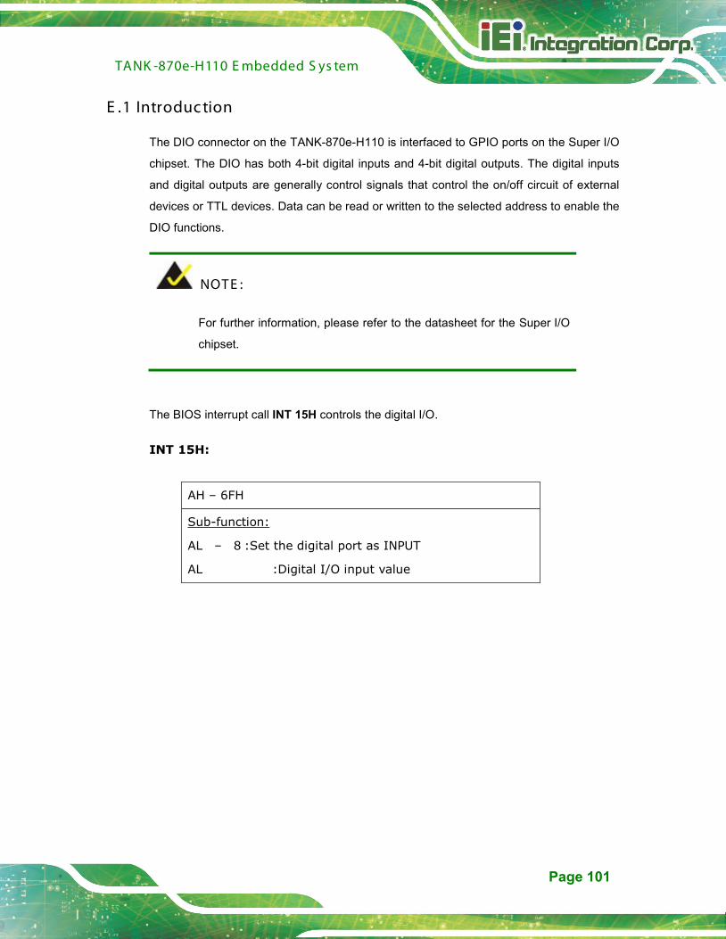
TANK -870e-H110 E mbedded S ys tem
Page 101
E .1 Introduc tion
The DIO connector on the TANK-870e-H110 is interfaced to GPIO ports on the Super I/O
chipset. The DIO has both 4-bit digital inputs and 4-bit digital outputs. The digital inputs
and digital outputs are generally control signals that control the on/off circuit of external
devices or TTL devices. Data can be read or written to the selected address to enable the
DIO functions.
NOT E :
For further information, please refer to the datasheet for the Super I/O
chipset.
The BIOS interrupt call INT 15H controls the digital I/O.
INT 15H:
AH – 6FH
AL – 8 :Set the digital port as INPUT
Sub-function:
AL :Digital I/O input value
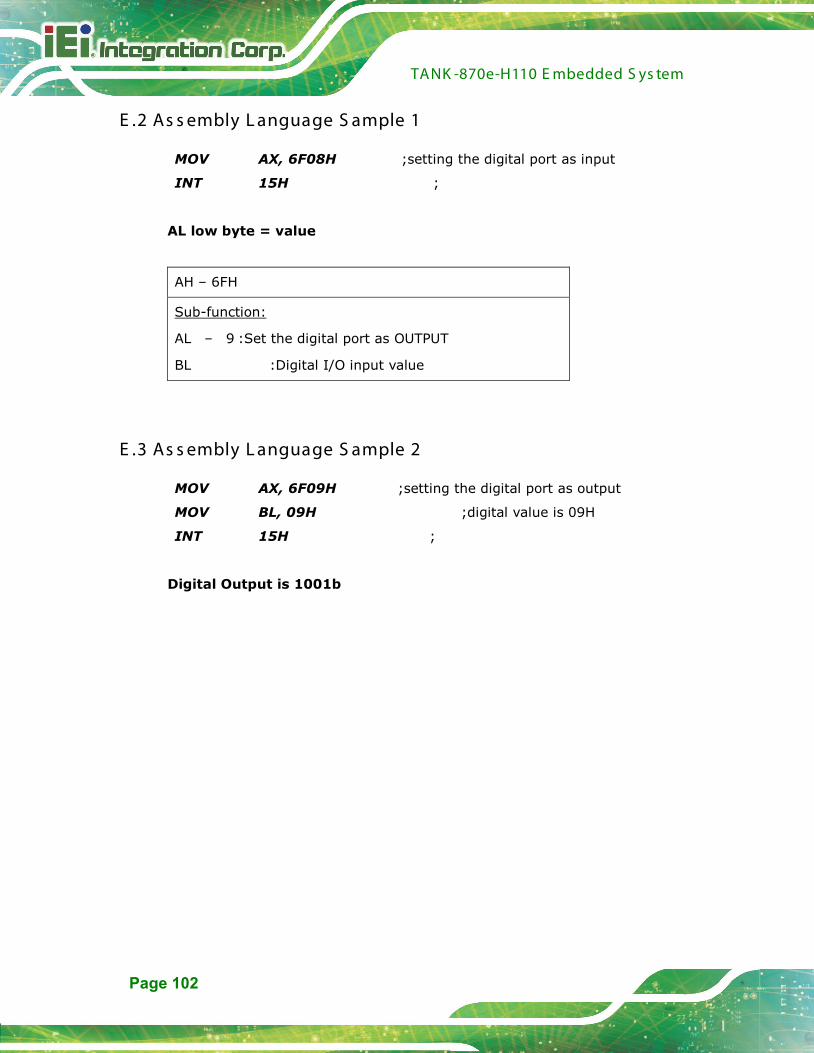
TANK -870e-H110 E mbedded S ys tem
Page 102
E .2 As s embly L anguage S ample 1
MOV AX, 6F08H ;setting the digital port as input
INT 15H ;
AL low byte = value
AH – 6FH
AL – 9 :Set the digital port as OUTPUT
Sub-function:
BL :Digital I/O input value
E .3 As s embly L anguage S ample 2
MOV AX, 6F09H ;setting the digital port as output
MOV BL, 09H ;digital value is 09H
INT 15H ;
Digital Output is 1001b

TANK -870e-H110 E mbedded S ys tem
Page 103
Appendix
F
F Hazardous Materials Dis c los ure
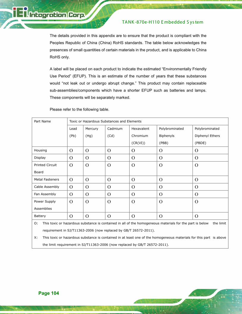
TANK -870e-H110 E mbedded S ys tem
Page 104
The details provided in this appendix are to ensure that the product is compliant with the
Peoples Republic of China (China) RoHS standards. The table below acknowledges the
presences of small quantities of certain materials in the product, and is applicable to China
RoHS only.
A label will be placed on each product to indicate the estimated “Environmentally Friendly
Use Period” (EFUP). This is an estimate of the number of years that these substances
would “not leak out or undergo abrupt change.” This product may contain replaceable
sub-assemblies/components which have a shorter EFUP such as batteries and lamps.
These components will be separately marked.
Please refer to the following table.
Part Name Toxic or Hazardous Substances and Elements
Lead
(Pb)
Mercury
(Hg)
Cadmium
(Cd)
Hexavalent
Chromium
(CR(VI))
Polybrominated
Biphenyls
(PBB)
Polybrominated
Diphenyl Ethers
(PBDE)
Housing O O O O O O Display O O O O O O Printed Circuit
Board
O O O O O O
Metal Fasteners O O O O O O Cable Assembly O O O O O O Fan Assembly O O O O O O Power Supply
Assemblies
O O O O O O
Battery O O O O O O O: This toxic or hazardous substance is contained in all of the homogeneous materials for the part is below the limit
requirement in SJ/T11363-2006 (now replaced by GB/T 26572-2011).
X: This toxic or hazardous substance is contained in at least one of the homogeneous materials for this part is above
the limit requirement in SJ/T11363-2006 (now replaced by GB/T 26572-2011).

TANK -870e-H110 E mbedded S ys tem
Page 105
此附件旨在确保本产品符合中国 RoHS 标准。以下表格标示此产品中某有毒物质的含量符
合中国 RoHS 标准规定的限量要求。
本产品上会附有”环境友好使用期限”的标签,此期限是估算这些物质”不会有泄漏或突变”的
年限。本产品可能包含有较短的环境友好使用期限的可替换元件,像是电池或灯管,这些元
件将会单独标示出来。
部件名称 有毒有害物质或元素
铅
(P b)
汞
(Hg)
镉
(C d)
六价铬
(C R (VI))
多溴联苯
(P B B )
多溴二苯
醚
(P B DE )
壳体 O O O O O O
显示 O O O O O O
印刷电路板 O O O O O O
金属螺帽 O O O O O O
电缆组装 O O O O O O
风扇组装 O O O O O O
电力供应组装 O O O O O O
电池 O O O O O O
O: 表示该有毒有害物质在该部件所有物质材料中的含量均在 SJ/T 11363-2006 (现由 GB/T 26572-2011 取代)
标准规定的限量要求以下。
X: 表示该有毒有害物质至少在该部件的某一均质材料中的含量超出 SJ/T 11363-2006 (现由 GB/T
26572-2011 取代) 标准规定的限量要求。