MODEL T27359 MINI SANDBLAST CABINET OWNER'S …cdn1.grizzly.com/manuals/t27359_m.pdf · ·...
32
MODEL T27359 MINI SANDBLAST CABINET OWNER'S MANUAL (For models manufactured since 02/15) COPYRIGHT © NOVEMBER, 2016 BY GRIZZLY INDUSTRIAL, INC. WARNING: NO PORTION OF THIS MANUAL MAY BE REPRODUCED IN ANY SHAPE OR FORM WITHOUT THE WRITTEN APPROVAL OF GRIZZLY INDUSTRIAL, INC. #JH18230 PRINTED IN CHINA V1.11.16
-
Upload
truongdieu -
Category
Documents
-
view
215 -
download
0
Transcript of MODEL T27359 MINI SANDBLAST CABINET OWNER'S …cdn1.grizzly.com/manuals/t27359_m.pdf · ·...

MODEL T27359MINI SANDBLAST CABINET
OWNER'S MANUAL(For models manufactured since 02/15)
COPYRIGHT © NOVEMBER, 2016 BY GRIZZLY INDUSTRIAL, INC. WARNING: NO PORTION OF THIS MANUAL MAY BE REPRODUCED IN ANY SHAPE
OR FORM WITHOUT THE WRITTEN APPROVAL OF GRIZZLY INDUSTRIAL, INC.#JH18230 PRINTED IN CHINA V1.11.16

This manual provides critical safety instructions on the proper setup, operation, maintenance, and service of this machine/tool. Save this document, refer to it often, and use it to instruct other operators.
Failure to read, understand and follow the instructions in this manual may result in fire or serious personal injury—including amputation, electrocution, or death.
The owner of this machine/tool is solely responsible for its safe use. This responsibility includes but is not limited to proper installation in a safe environment, personnel training and usage authorization, proper inspection and maintenance, manual availability and compre-hension, application of safety devices, cutting/sanding/grinding tool integrity, and the usage of personal protective equipment.
The manufacturer will not be held liable for injury or property damage from negligence, improper training, machine modifications or misuse.
Some dust created by power sanding, sawing, grinding, drilling, and other construction activities contains chemicals known to the State of California to cause cancer, birth defects or other reproductive harm. Some examples of these chemicals are:
• Lead from lead-based paints.• Crystalline silica from bricks, cement and other masonry products.• Arsenic and chromium from chemically-treated lumber.
Your risk from these exposures varies, depending on how often you do this type of work. To reduce your exposure to these chemicals: Work in a well ventilated area, and work with approved safety equip-ment, such as those dust masks that are specially designed to filter out microscopic particles.

INTRODUCTION ............................................................................................................................... 2Manual Accuracy ........................................................................................................................ 2Machine Data Sheet ................................................................................................................... 2Contact Info ................................................................................................................................ 2Identification ............................................................................................................................... 3Controls & Components ............................................................................................................. 4
SECTION 1: SAFETY ....................................................................................................................... 5Safety Instructions for Machinery ............................................................................................... 5Additional Safety for Sandblast Cabinets ................................................................................... 7
SECTION 2: SETUP ......................................................................................................................... 8Unpacking .................................................................................................................................. 8Needed for Setup ....................................................................................................................... 8Inventory ..................................................................................................................................... 8Site Considerations .................................................................................................................... 9Assembly .................................................................................................................................... 9Air System Setup ..................................................................................................................... 10Dust Collection ......................................................................................................................... 11Test Run ................................................................................................................................... 12
SECTION 3: OPERATIONS ........................................................................................................... 13Operation Overview.................................................................................................................. 13Basic Operation ........................................................................................................................ 14Operation Tips .......................................................................................................................... 15Abrasive Options ...................................................................................................................... 16
SECTION 4: ACCESSORIES ......................................................................................................... 17
SECTION 5: MAINTENANCE......................................................................................................... 18Schedule .................................................................................................................................. 18Cleaning & Protecting .............................................................................................................. 18
SECTION 6: SERVICE ................................................................................................................... 19Replacing Filter ........................................................................................................................ 19Replacing Bulb ......................................................................................................................... 19Replacing ................................................................................................................................ 20Protective Cover ....................................................................................................................... 20Replacing ................................................................................................................................ 20Abrasive Material...................................................................................................................... 20
SECTION 7: WIRING ...................................................................................................................... 21Wiring Safety Instructions ........................................................................................................ 21Wiring Diagram......................................................................................................................... 22Air System Diagram ................................................................................................................. 23
SECTION 8: PARTS ....................................................................................................................... 24Main .......................................................................................................................................... 24Main Parts List ......................................................................................................................... 25Labels & Cosmetics ................................................................................................................. 26
WARRANTY & RETURNS ............................................................................................................. 29
Table of Contents

INTRODUCTION
Manual Accuracy
We are proud to offer this document with your new machine! We've made every effort to be exact with the instructions, specifications, draw-ings, and photographs of the machine we used when writing this manual. However, sometimes we still make an occasional mistake.
Also, owing to our policy of continuous improve-ment, your machine may not exactly match the manual. If you find this to be the case, and the difference between the manual and machine leaves you in doubt, immediately call our techni-cal support for updates or clarification.
For your convenience, we post all available docu-mentation on our website at www.grizzly.com. Any updates to this document will be reflected on our website as soon as complete.
Contact Info
We stand behind our machines! If you have ques-tions or need help, contact us with the information below. Before contacting, make sure you get the serial number and manufacture date from the machine ID label. This will help us help you faster.
Grizzly Technical Support1815 W. Battlefield
Springfield, MO 65807Phone: (570) 546-9663
Email: [email protected]
We want your feedback on this manual. What did you like about it? Where could it be improved? Please take a few minutes to give us feedback.
Grizzly Documentation ManagerP.O. Box 2069
Bellingham, WA 98227-2069Email: [email protected]
Design Type ..................................................................... Benchtop ModelGeneral Specifications: Width x Depth x Height .........................................183⁄4" x 141⁄4" x 141⁄2" Operating Air Pressure Range ........................................... 60-100 PSI Recommended Air Supply .................................................... 5-14 CFM Net Weight ..................................................................................50 lbs. Abrasive Capacity .......................................................................12 lbs. Abrasive Type ......................................................................... Dry Only Lighting Type ...........................................................................LED Bar Load & Unload Access ................................................................... Top Power Supply ..................................... 110VAC w/12VDC Transformer Included Plug Type ........................................................................ 1-15 Full-Load Current Rating ..................................................................5A Minimum Circuit Size ......................................................................15A
Specifications, while deemed accurate, are not guaranteed.
Customer Service #: (570) 546-9663 • To Order Call: (800) 523-4777 • Fax #: (800) 438-5901
MACHINE DATA SHEET
MODEL T27359 SANDBLAST CABINET
Model T27359 (Mfd. Since 02/15) -3-
Identification
To reduce your risk of serious injury, read this entire manual BEFORE using machine.
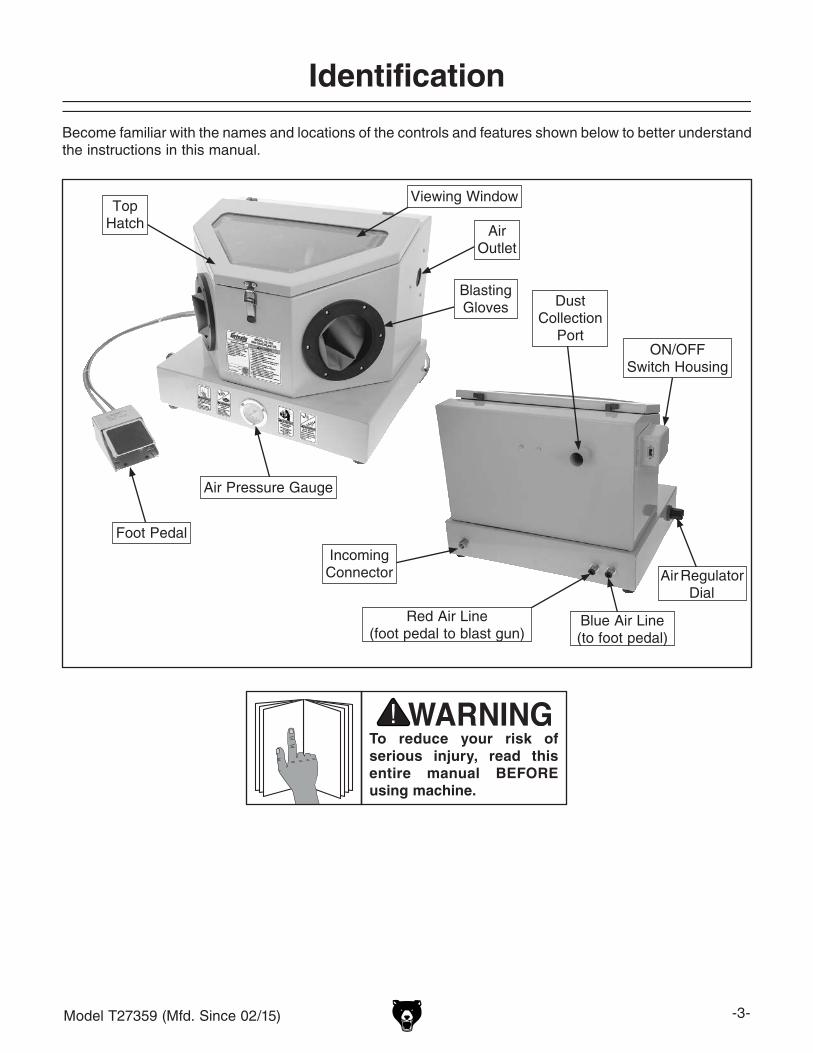
Become familiar with the names and locations of the controls and features shown below to better understand the instructions in this manual.
Air Regulator Dial
Blue Air Line(to foot pedal)
Red Air Line (foot pedal to blast gun)
Air Pressure Gauge
IncomingConnector
Foot Pedal
ON/OFFSwitch Housing
Blasting Gloves
Air Outlet
Dust Collection
Port
Top Hatch
Viewing Window
-4- Model T27359 (Mfd. Since 02/15)
Controls & Components
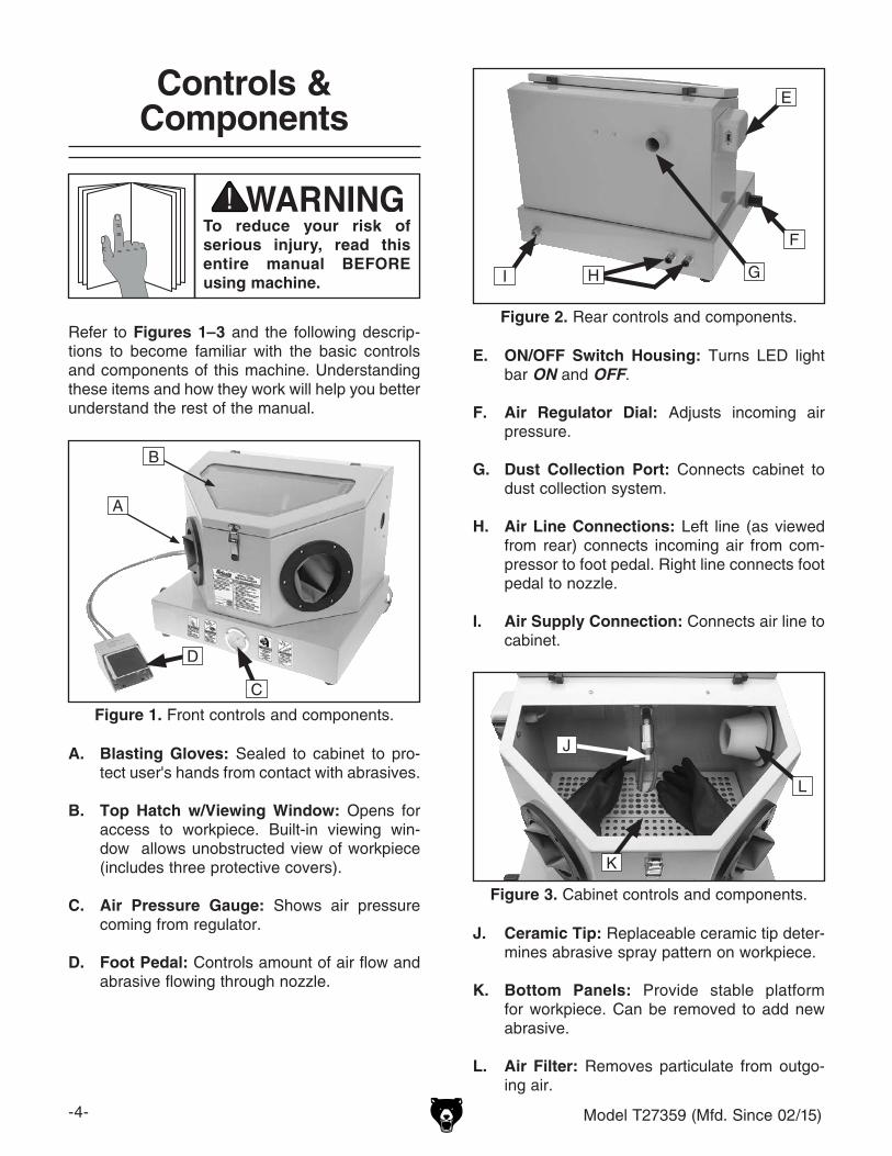
Refer to Figures 1–3 and the following descrip-tions to become familiar with the basic controls and components of this machine. Understanding these items and how they work will help you better understand the rest of the manual.
To reduce your risk of serious injury, read this entire manual BEFORE using machine.
Figure 1. Front controls and components.
A
B
C
D
A. Blasting Gloves: Sealed to cabinet to pro-tect user's hands from contact with abrasives.
B. Top Hatch w/Viewing Window: Opens for access to workpiece. Built-in viewing win-dow allows unobstructed view of workpiece (includes three protective covers).
C. Air Pressure Gauge: Shows air pressure coming from regulator.
D. Foot Pedal: Controls amount of air flow and abrasive flowing through nozzle.
Figure 2. Rear controls and components.
E
F
GI
E. ON/OFF Switch Housing: Turns LED light bar ON and OFF.
F. Air Regulator Dial: Adjusts incoming air pressure.
G. Dust Collection Port: Connects cabinet to dust collection system.
H. Air Line Connections: Left line (as viewed from rear) connects incoming air from com-pressor to foot pedal. Right line connects foot pedal to nozzle.
I. Air Supply Connection: Connects air line to cabinet.
J. Ceramic Tip: Replaceable ceramic tip deter-mines abrasive spray pattern on workpiece.
K. Bottom Panels: Provide stable platform for workpiece. Can be removed to add new abrasive.
L. Air Filter: Removes particulate from outgo-ing air.
Figure 3. Cabinet controls and components.
J
L
K
H

Model T27359 (Mfd. Since 02/15) -5-
ELECTRICAL EQUIPMENT INJURY RISKS. You can be shocked, burned, or killed by touching live electrical components or improperly grounded machinery. To reduce this risk, only allow qualified service personnel to do electrical installation or repair work, and always disconnect power before accessing or exposing electrical equipment.
DISCONNECT POWER FIRST. Always discon-nect machine from power supply BEFORE making adjustments, changing tooling, or servicing machine. This prevents an injury risk from unintended startup or contact with live electrical components.
EYE PROTECTION. Always wear ANSI-approved safety glasses or a face shield when operating or observing machinery to reduce the risk of eye injury or blindness from flying particles. Everyday eyeglasses are NOT approved safety glasses.
OWNER’S MANUAL. Read and understand this owner’s manual BEFORE using machine.
TRAINED OPERATORS ONLY. Untrained oper-ators have a higher risk of being hurt or killed. Only allow trained/supervised people to use this machine. When machine is not being used, dis-connect power, remove switch keys, or lock-out machine to prevent unauthorized use—especially around children. Make workshop kid proof!
DANGEROUS ENVIRONMENTS. Do not use machinery in areas that are wet, cluttered, or have poor lighting. Operating machinery in these areas greatly increases the risk of accidents and injury.
MENTAL ALERTNESS REQUIRED. Full mental alertness is required for safe operation of machin-ery. Never operate under the influence of drugs or alcohol, when tired, or when distracted.
For Your Own Safety, Read Instruction Manual Before Operating This Machine
The purpose of safety symbols is to attract your attention to possible hazardous conditions. This manual uses a series of symbols and signal words intended to convey the level of impor-tance of the safety messages. The progression of symbols is described below. Remember that safety messages by themselves do not eliminate danger and are not a substitute for proper accident prevention measures. Always use common sense and good judgment.
Indicates a potentially hazardous situation which, if not avoided, MAY result in minor or moderate injury. It may also be used to alert against unsafe practices.
Indicates a potentially hazardous situation which, if not avoided, COULD result in death or serious injury.
Indicates an imminently hazardous situation which, if not avoided, WILL result in death or serious injury.
This symbol is used to alert the user to useful information about proper operation of the machine.NOTICE
Safety Instructions for Machinery
SECTION 1: SAFETY

-6- Model T27359 (Mfd. Since 02/15)
WEARING PROPER APPAREL. Do not wear clothing, apparel or jewelry that can become entangled in moving parts. Always tie back or cover long hair. Wear non-slip footwear to reduce risk of slipping and losing control or accidentally contacting cutting tool or moving parts.
HAZARDOUS DUST. Dust created by machinery operations may cause cancer, birth defects, or long-term respiratory damage. Be aware of dust hazards associated with each workpiece mate-rial. Always wear a NIOSH-approved respirator to reduce your risk.
HEARING PROTECTION. Always wear hear-ing protection when operating or observing loud machinery. Extended exposure to this noise without hearing protection can cause permanent hearing loss.
REMOVE ADJUSTING TOOLS. Tools left on machinery can become dangerous projectiles upon startup. Never leave chuck keys, wrenches, or any other tools on machine. Always verify removal before starting!
USE CORRECT TOOL FOR THE JOB. Only use this tool for its intended purpose—do not force it or an attachment to do a job for which it was not designed. Never make unapproved modifica-tions—modifying tool or using it differently than intended may result in malfunction or mechanical failure that can lead to personal injury or death!
AWKWARD POSITIONS. Keep proper footing and balance at all times when operating machine. Do not overreach! Avoid awkward hand positions that make workpiece control difficult or increase the risk of accidental injury.
CHILDREN & BYSTANDERS. Keep children and bystanders at a safe distance from the work area.Stop using machine if they become a distraction.
GUARDS & COVERS. Guards and covers reduce accidental contact with moving parts or flying debris. Make sure they are properly installed, undamaged, and working correctly BEFORE operating machine.
FORCING MACHINERY. Do not force machine. It will do the job safer and better at the rate for which it was designed.
NEVER STAND ON MACHINE. Serious injury may occur if machine is tipped or if the cutting tool is unintentionally contacted.
STABLE MACHINE. Unexpected movement dur-ing operation greatly increases risk of injury or loss of control. Before starting, verify machine is stable and mobile base (if used) is locked.
USE RECOMMENDED ACCESSORIES. Consult this owner’s manual or the manufacturer for rec-ommended accessories. Using improper acces-sories will increase the risk of serious injury.
UNATTENDED OPERATION. To reduce the risk of accidental injury, turn machine OFF and ensure all moving parts completely stop before walking away. Never leave machine running while unattended.
MAINTAIN WITH CARE. Follow all maintenance instructions and lubrication schedules to keep machine in good working condition. A machine that is improperly maintained could malfunction, leading to serious personal injury or death.
DAMAGED PARTS. Regularly inspect machine for damaged, loose, or mis-adjusted parts—or any condition that could affect safe operation. Immediately repair/replace BEFORE operating machine. For your own safety, DO NOT operate machine with damaged parts!
MAINTAIN POWER CORDS. When disconnect-ing cord-connected machines from power, grab and pull the plug—NOT the cord. Pulling the cord may damage the wires inside. Do not handle cord/plug with wet hands. Avoid cord damage by keeping it away from heated surfaces, high traffic areas, harsh chemicals, and wet/damp locations.
EXPERIENCING DIFFICULTIES. If at any time you experience difficulties performing the intend-ed operation, stop using the machine! Contact our Technical Support at (570) 546-9663.

Model T27359 (Mfd. Since 02/15) -7-
Additional Safety for Sandblast Cabinets
SAFE MEDIA BLASTING. Only use clean, dry, regulated compressed air. Never exceed maximum operating pressure or lines and seals may burst and cause injury. Never use oxygen, carbon dioxide, combustible gases, or any bottled gas as an air source, as these can explode.
CHECKING FOR LEAKS. To prevent accidental contamination of shop air, check blast cabinet for leaks before and during use, verify connections are tight, and immediately seal any leaks, if found. If leaks are found during operation, immediately stop using blast cabinet and repair leaks immediately before resuming use.
AVOIDING TOXIC DUST EXPOSURE. Always use low toxicity abrasives and avoid blasting workpieces containing crystalline silica, lead, asbestos, or radioactive substances.
LEAVING UNATTENDED. To prevent accidental injury, explosion, or air contamination, disconnect air supply when leaving blast cabinet.
AVOIDING ENTRAPMENT. To prevent entrapment hazard for animals or children, always close and latch blast cabinet hood/door(s) when not in use.
SAFE MAINTENANCE. To prevent accidental blasting injury or shock, disconnect air supply and power before loading and unloading workpiece, and before doing maintenance or changing blast tips.
USING CORRECT LIGHTING. To prevent ballast overload and possible fire or explosion, only install bulb(s) designed for blast cabinet.
LUNG, EAR, EYE PROTECTION. Media blasting presents a real hazard of silicosis and other lung contamination injuries! These injuries are permanent and can get worse over time. ALWAYS use proper blast cabinet hood, eye and ear protection, and properly fitted and maintained NIOSH-approved respirator to reduce risk of eyes, ears, and lungs becoming permanently damaged. Protect yourself correctly, and keep all unprotected bystanders away. For latest types of protective equipment and acceptable respirator types, contact your local OSHA or NIOSH office.
REDUCING RISK OF FIRE & EXPLOSIONS. Some abrasive particles can create sparks, which can ignite explosive or flammable materials. DO NOT use blast cabinet near explosive or flammable materials; move these types of materials a safe distance away.
SAFE ENVIRONMENT. To avoid media escaping through cabinet air outlet, only use blast cabinet if dust collector is ON and collector filter is unclogged. After blasting, continue running dust collector long enough to clear cabinet of dust before opening hood/door(s). Close and latch hood/door(s) shut before and after operation. Properly dispose of collected dust to avoid contaminating shop air. Use dust collection system correctly sized for blast cabinet and abrasive type/size.
MAINTAINING COMPONENTS. To prevent accidental contamination or blast injury, replace tips, hoses, lenses, and gloves when they become worn, and clean dust collector and filters often. Avoid spraying media at rubber gloves.
Long-term respiratory, hearing, and vision injuries can occur from using sandblasting abrasives without proper use of personal protective equipment and an adequate dust collection system. Sparks from abrasive particles can ignite explosive or flammable materials. To minimize risk of getting injured, anyone operating machine MUST completely heed hazards and warnings below.

-8- Model T27359 (Mfd. Since 02/15)
SECTION 2: SETUP
This machine was carefully packaged for safe transport. When unpacking, separate all enclosed items from packaging materials and inspect them for shipping damage. If items are damaged, please call us immediately at (570) 546-9663.
IMPORTANT: Save all packaging materials until you are completely satisfied with the machine and have resolved any issues between Grizzly or the shipping agent. You MUST have the original pack-aging to file a freight claim. It is also extremely helpful if you need to return your machine later.
Unpacking
SUFFOCATION HAZARD!Keep children and pets away from plastic bags or packing materials shipped with this machine. Discard immediately.
The following items are needed, but not included, for the setup/assembly of this machine.
Description Qty• Male Air Fitting 1⁄4" NPT .............................. 1• Safety Glasses ........................................... 1• Cleaner/Degreaser ..................... As Needed• Disposable Shop Rags ............... As Needed• Adjustable Wrench ..................................... 1• Thread Seal Tape ....................... As Needed• Abrasive Media .................................12 lbs.
Needed for Setup
Inventory
The following is a list of items shipped with your machine. Before beginning setup, lay these items out and inventory them.
If any non-proprietary parts are missing (e.g. a nut or a washer), we will gladly replace them; or for the sake of expediency, replacements can be obtained at your local hardware store.
Component Inventory (Figure 4) QtyA. Sandblast Cabinet (not shown) .................. 1B. Power Adapter ............................................ 1C. Foot Pedal .................................................. 1D. Window Protective Covers ......................... 3E. Replacement Ceramic Tips ........................ 2
NOTICEIf you cannot find an item on this list, care-fully check around/inside the machine and packaging materials. Often, these items get lost in packaging materials while unpack-ing or they are pre-installed at the factory.
Figure 4. T27359 inventory.
B
C
D
E

Model T27359 (Mfd. Since 02/15) -9-
Assembly
To assemble machine:
1. Connect red and blue foot pedal air lines to back of sandblast cabinet by pressing air line end into connector, as shown in Figure 6.
Note: To detach air line, push in on connec-tor collar and hold, and then pull air line out.
The machine must be fully assembled before it can be operated. Before beginning the assembly process, refer to Needed for Setup and gather all listed items. To ensure the assembly process goes smoothly, first clean any parts that are cov-ered or coated in heavy-duty rust preventative (if applicable).
Site Considerations
Figure 5. Minimum working clearances.
141/4"
183/4"
Wall
Min. 12" for Air Line Clearance
Children and visitors may be seriously injured if unsuper-vised around this machine. Lock entrances to the shop or disable start switch or power connection to prevent unsupervised use.
Workbench LoadRefer to the Machine Data Sheet for the weight and footprint specifications of your machine. Some workbenches may require additional rein-forcement to support the weight of the machine and workpiece materials.
Consider anticipated workpiece sizes and addi-tional space needed for auxiliary stands, work tables, or other machinery when establishing a location for this machine in the shop. Below is the minimum amount of space needed for the machine.
Placement Location
Figure 6. Attaching air lines to cabinet.
Collar
ConnectorsRed Air Line
Blue Air Line
Collar
2. Wrap thread seal tape around threads of male air fitting 1⁄4" NPT (not included) for a tight seal. Attach plug to back of sandblast cabinet (see Figure 7) and tighten with a wrench to ensure no air leakage when attached to com-pressor.
Figure 7. Attaching air fitting to back of cabinet.

-10- Model T27359 (Mfd. Since 02/15)
Air System Setup
Air SupplyThe ability of this blast cabinet to accomplish its task is directly related to how well the air supply system is designed. For this blast cabinet to oper-ate at its maximum potential, the air supply must be able to deliver between 5–14 CFM at 60–100 PSI.
Refer to your compressor Owner’s Manual and make sure that the compressor can handle the air requirements for this blast cabinet. Smaller compressors can be used, but the duration of the work shift must be reduced to avoid exceeding compressor duty cycle. Not allowing the com-pressor to cool will lead to compressor or motor failure. The smaller the compressor, the longer cool-down time that will be required between the work cycles.
If using smaller compressors, make sure to ser-vice the compressor more frequently, and verify that your compressor has the best cooling airflow possible.
When filling or servicing the blast cabinet, there is a risk of subjecting the compressor to airborne media or dust. Be sure to locate the blast cabinet away from the compressor operating environ-ment. If even small amounts of media dust enter the compressor through the intake or during gen-eral service, the piston rings, valves, and bearings can be quickly destroyed.
If an air compressor is not available or the blast cabinet is to be used in a remote location, NEVER connect blast cabinet to pressurized bottled gas-ses, such as oxygen bottles used for welding operations. Line ruptures or explosions can occur, causing equipment damage, serious injury, or death.
Figure 8. Attaching protective cover to inside of top hatch.
3. Attach protective cover to inside of top hatch viewing window (see Figure 8).
4. Remove bottom panels and add abrasive material to hopper (see Figure 9).
Figure 9. Adding abrasive material to hopper.
5. Re-install bottom panels (see Figure 10) and close top hatch.
Figure 10. Re-installing panel inside cabinet.

Model T27359 (Mfd. Since 02/15) -11-
Air PlumbingInstall the air supply lines with a slight tilt back toward the compressor tank or drain valve, so the moisture that accumulates from condensation will drain back into the compressor tank or drain valve instead of puddling in the low areas of the air lines.
Install an in-line water separator or an air dryer as close to the blast cabinet as possible where the air has had the most time to cool. Water separa-tors typically work best on cool air rather than on hot air that comes right out of the compressor tank.
If using an existing air system, eliminate air supply restrictions and pressure drops that may occur at small quick-disconnect fittings, elbows, small sup-ply piping, undersized water separators, kinked lines, or rust-filled piping.
Remove any in-line oilers that are installed direct-ly in the blast cabinet air supply line. Otherwise the media and blast cabinet will become contami-nated with oil, and blasting operations will quickly come to a halt. Air supply lines for other machines that have in-line oilers need not be removed, as long as these lines only feed from the blast cabi-net supply line.
Make sure to install an air supply quick-discon-nect fitting or a shut-off valve that can be locked out to prevent the air pressure from accidentally being turned on. These items allow for the blast cabinet to be serviced safely or allow it to sit idle when not in use.
Dust Collection
To connect dust collection system to machine:
1. Fit a 11⁄8" dust hose over dust port, as shown in Figure 11, and secure in place with a hose clamp.
2. Tug hose to make sure it does not come off.
Note: A tight fit is necessary for proper performance.
Minimum CFM at Dust Port: 100 CFMDo not confuse this CFM recommendation with the rating of the dust collector. To determine the CFM at the dust port, you must consider these variables: (1) CFM rating of the dust collector, (2) hose type and length between the dust col-lector and the machine, (3) number of branches or wyes, and (4) amount of other open lines throughout the system. Explaining how to cal-culate these variables is beyond the scope of this manual. Consult an expert or purchase a good dust collection "how-to" book.
This machine creates substantial amounts of dust during operation. Breathing air-borne dust on a regular basis can result in permanent respiratory illness. Reduce your risk by wearing a respirator and capturing the dust with a dust collection system.
Figure 11. Dust hose attached to dust port.
Dust Port
-12- Model T27359 (Mfd. Since 02/15)
Test Run
Once assembly is complete, test run the machine to ensure it is properly connected to power and safety components are functioning correctly.
If you find an unusual problem during the test run, immediately stop the machine, disconnect it from power, and fix the problem BEFORE operating the machine again. The Troubleshooting table in the SERVICE section of this manual can help.
DO NOT start machine until all preceding setup instructions have been performed. Operating an improperly set up machine may result in malfunction or unexpect-ed results that can lead to serious injury, death, or machine/property damage.
Serious injury or death can result from using this machine BEFORE understanding its controls and related safety information. DO NOT operate, or allow others to operate, machine until the information is understood.
The test run consists of ensuring machine oper-ates properly when pressurized, air regulator functions correctly, and LED light works.
To test run machine:
1. Make sure you understand all safety instruc-tions from the beginning of the manual, and machine is set up properly.
2. Make sure all tools and objects used during setup are cleared away from machine.
3. Make sure ON/OFF rocker switch is in OFF position.
4. Connect machine to power.
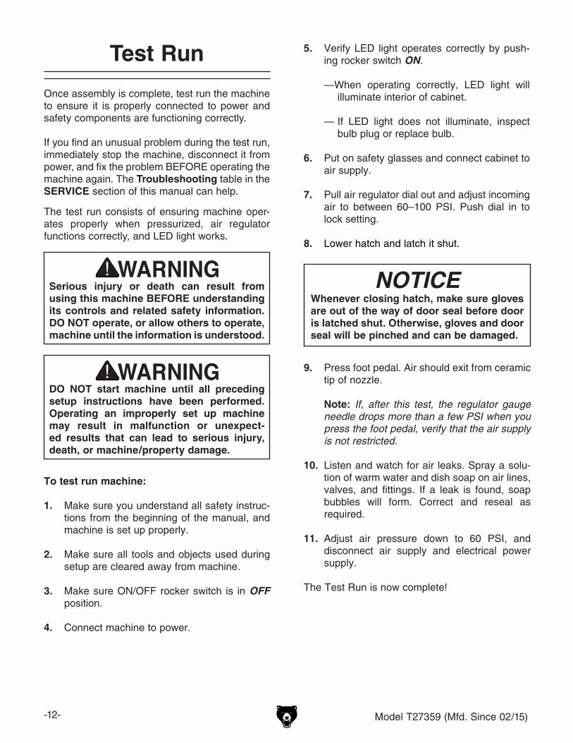
5. Verify LED light operates correctly by push-ing rocker switch ON.
—When operating correctly, LED light will illuminate interior of cabinet.
— If LED light does not illuminate, inspect bulb plug or replace bulb.
6. Put on safety glasses and connect cabinet to air supply.
7. Pull air regulator dial out and adjust incoming air to between 60–100 PSI. Push dial in to lock setting.
8. Lower hatch and latch it shut.
NOTICEWhenever closing hatch, make sure gloves are out of the way of door seal before door is latched shut. Otherwise, gloves and door seal will be pinched and can be damaged.
9. Press foot pedal. Air should exit from ceramic tip of nozzle.
Note: If, after this test, the regulator gauge needle drops more than a few PSI when you press the foot pedal, verify that the air supply is not restricted.
10. Listen and watch for air leaks. Spray a solu-tion of warm water and dish soap on air lines, valves, and fittings. If a leak is found, soap bubbles will form. Correct and reseal as required.
11. Adjust air pressure down to 60 PSI, and disconnect air supply and electrical power supply.
The Test Run is now complete!

Model T27359 (Mfd. Since 02/15) -13-
SECTION 3: OPERATIONS
Operation Overview
The purpose of this overview is to provide the nov-ice machine operator with a basic understanding of how the machine is used during operation, so the machine controls/components discussed later in this manual are easier to understand.
Due to the generic nature of this overview, it is not intended to be an instructional guide. To learn more about specific operations, read this entire manual and seek additional training from expe-rienced machine operators, and do additional research outside of this manual by reading "how-to" books, trade magazines, or websites.
To reduce your risk of serious injury, read this entire manual BEFORE using machine.
To reduce risk of eye injury from flying chips or lung damage from breathing dust, always wear safety glasses and a respirator when operating this machine.
Sandblasting presents a real hazard of silicosis and other lung contamination injuries! These injuries are permanent and can get worse over time. If you use media blasting equipment without the proper eye protection and respirator, your eyes and lungs may become irreversibly contaminated. Only use this blast cabinet if you are properly trained in how to use it, correctly protect yourself, and keep all unprotected bystanders away. For the latest types of protective equipment and acceptable respirator types, contact your local OSHA or NIOSH office.
If you have never used this type of machine or equipment before, WE STRONGLY REC-OMMEND that you read books, trade maga-zines, or get formal training before begin-ning any projects. Regardless of the con-tent in this section, Grizzly Industrial will not be held liable for accidents caused by lack of training.

-14- Model T27359 (Mfd. Since 02/15)
NEVER sandblast with the doors open or attempt to service any part of this machine while it is plugged in or connected to air pressure. ALWAYS disconnect the blast cabinet from power and air pressure when not in use, or during maintenance or adjust-ments. Ignoring this warning may lead to severe injury.
4. Remove bottom panels. Carefully add approximately 12 lbs. of abrasive into sandblaster without causing a hazardous dust cloud. DO NOT overfill, or sandblasting will be sluggish and very cloudy inside of cabinet.
5. Insert workpiece, then close and lock top hatch.
6. Adjust air supply regulator to 60–100 PSI at 5–14 CFM.
7. Clean filter cover, and ensure incoming compressor line is free of moisture.
8. Turn ON dust collection/vacuum system and air compressor, insert hands in gloves, and begin sandblasting in a slow circular motion.
Note: A good starting point for tip distance is two inches away from the workpiece. Start out with a low air pressure setting to avoid excess peening and abrasive wear.
Figure 12. Ceramic tip installed in blast nozzle.
Blast Nozzle
Nozzle Body
Ceramic Tip
Basic Operation
The Model T27359 sandblast cabinet is equipped with a blast nozzle with a ceramic tip, a siphon hose, a built-in light, large viewing window, and sealed rubber gloves. The hopper beneath the removable bottom panel recycles and stores the abrasive media for re-use or easy removal. Safely blast away paint and rust without making a mess around your shop.
Note: Experiment with different pressures and abrasives to gain practical experience.
Note: Keep the sandblasting abrasives moisture-free, otherwise the nozzle tip will frequently clog.
To use sandblast cabinet:
1. Wear safety glasses and respirator at all times when running and maintaining sandblast cabinet!
2. Plug in AC/DC transformer and turn light ON.
3. Unscrew and remove blast nozzle (see Figure 12). Install ceramic tip.

Model T27359 (Mfd. Since 02/15) -15-
Operation Tips
Improving ProductivityClean workpieces as much as possible by removing grease, oils, paint, rust, scale and other matter before beginning blasting operations. (Pressure washers can work well for this.) Select the correct media for the task, and do not use air pressure settings that are too high for the media as it will cause media breakdown and dulling.
Maintaining VisibilityShould poor visibility become a problem during blasting operations, do not wipe the windows clean with wet or dry rags. Doing so will scratch the protective plastic sheet, further reducing visibility. Instead, vacuum media away with a soft brush attachment, or use a soft paint brush to brush the dust off of the protective sheets.
Protecting Window GlassAlways make sure to inspect and replace the protective sheets BEFORE the ricochetting media wears through and permanently etches the underlying glass. If using an aggressive media, this is especially true, and you may have to double the sheets to protect from wear-through before the blasting project is finished.
Extending Protective Film LifeFor most media blasting operations, maintain a distance of six inches. Keep the spray at a 45°–60° angle to the workpiece, so the media will ricochet off it and not directly impact the bulb or viewing window. Doing this will help maintain workpiece visibility and make the protective window film and media last longer.
Air Pressure SettingsMost operations are done with air pressure settings between 60 –80 PSI. However, the optimum air pressure is derived from a trial-and-error process based on the factors discussed in the Abrasive Options section (see Page 16). If required, refer to that section for help.
Media AmountsLoading only enough media for the job at hand will help prevent over-using or having to screen excess media. Use just enough media to cover the suction tube opening at the bottom of the hopper. Experiment with using the least amount of media as possible. The result of using less media is that there will be less material to sift or discard and more fresh media for other projects. Store media in a dry place.
Maintaining Workpiece FinishAbrasive media will wear the ceramic tip causing an inconsistent blast pattern. A poor blast pattern will leave streaks or spots on the workpiece finish. To avoid this, rotate the ceramic tip 1⁄4-turn every 10 to 12 hours of use, and replace any tip that has worn larger than 1⁄16" in diameter from original size.
Recycling MediaSift used media with a series of wire mesh screens to refine it to one consistent size.
Air Pressure ExceptionsWhen blasting thin materials made of aluminum, copper, brass, wood, or other delicate parts, select a fine or soft media and begin blasting at a low pressure, such as 45 PSI. Next, slowly increase the air pressure until you achieve the finish required. When using glass bead media, you may have to keep the operating pressure between 50–80 PSI, or the media will shatter and break down prematurely. However, if using media like silicon carbide and aluminium oxide, you can keep pressures between 100–125 PSI.
Preventing & Clearing Clogs During blasting operations, the ceramic tip may periodically clog or become restricted with workpiece debris. If this occurs, cover the ceramic tip hole tightly with a flat section of scrap material, and press the foot valve. Air pressure will be diverted back through the suction circuit in the gun and piping, blowing out the clog. Blasting operations can be resumed afterwards; however, if clogging persists and the cause is other than workpiece debris, refer to Troubleshooting for further solutions.

-16- Model T27359 (Mfd. Since 02/15)
Abrasive Options
Blasting Media from Grizzly.comPART #G6535: 15 lbs. Aluminum Oxide 220-Grit.G6536: 15 lbs. Aluminum Oxide 120-Grit.G6537: 15 lbs. Aluminum Oxide 60-Grit.G6538: 15 lbs. Glass Bead 50-Micron Grit.
Glass and Garnet Type AbrasivesTypically this abrasive works well for soft metals and addressing surface issues with machine parts where tolerances must not be affected. The life of this abrasive is limited and not well suited for repetitively recycling.
Sand Type AbrasivesThis abrasive is easy to find, and gives an average finish that is acceptable for most projects. Sand has a good recycling life and is very economical.
Plastic Type Abrasives Applied at low pressures of 30 to 50 PSI, plas-tic abrasives should be harder than the coating being removed, but softer than the workpiece to avoid damage. Plastic abrasive is excellent for addressing surface issues on aluminum, magne-sium, copper, brass, thin steel, titanium, compos-ite surfaces, and fiberglass.
Other Types of Abrasives AvailableGround walnut or peanut shells.Ground corn cob.Sodium bicarbonate.Wheat starch.
Below is a basic introduction to some of the most common blasting abrasives. Refer to magazines, trade articles, professionals, and the abrasive manufacturer for the specific surfaces that can be addressed with a type of abrasive. All abra-sives have benefits and drawbacks like quality of surface finish, abrasive life, toxicity, and what precautions you must take to prevent environmen-tal damage or personal injury to your respiratory system.
Steel Type AbrasivesThis aggressive abrasive creates a rough fin-ish that accepts paint well. The abrasive is very durable and has a long life; however, it MUST be kept very dry to prevent rusting.
Alumina Type AbrasivesThis multi-purpose abrasive creates a smoother finish than the steel abrasives, but has a short-er life span. Less of the workpiece surface is removed with this more forgiving abrasive.

Model T27359 (Mfd. Since 02/15) -17-
SECTION 4: ACCESSORIESACCESSORIES
Installing unapproved accessories may cause machine to malfunction, resulting in serious personal injury or machine damage. To reduce this risk, only install accessories recommended for this machine by Grizzly.
NOTICERefer to our website or latest catalog for additional recommended accessories.
order online at www.grizzly.com or call 1-800-523-4777
T24156—Campbell Hausfeld™ 30-Gallon Oil Lube Cast-Iron Vertical CompressorThis 30-gallon air compressor provides the air power you need to tackle a wide range of jobs, from cutting and grinding to inflating and painting. You can depend on this unit’s cast-iron pump for long life operation in a home garage or automotive shop. Its portable design makes it easy to move around your garage or workshop.
Figure 13. T24156 30-Gallon Air Compressor.
H2499—Small Half-Mask RespiratorH3631—Medium Half-Mask RespiratorH3632—Large Half-Mask RespiratorH3635—Cartridge Filter Pair P100If you work around dust everyday, a half-mask respirator can be a lifesaver. Also compatible with safety glasses!
Figure 14. Half-mask respirator with disposable cartridge filters.
Figure 15. G6261 Campbell Hausfeld™ water filter.
G6261—Campbell Hausfeld™ Water FilterRemove damaging water vapor before it reaches your blast cabinet. This highly effective, five-micron filter features a see-through bowl and easy in-line connections. 150 PSI maximum air pres-sure. 1⁄4" NPT.

-18- Model T27359 (Mfd. Since 02/15)
SECTION 5: MAINTENANCE
For optimum performance from your machine, follow this maintenance schedule and refer to any specific instructions given in this section.
Daily Check• Inspect fittings, hoses, and cabinet seals for
leaks, cracks, abrasions, and wear.• Drain air line water separators.• Verify the air pressure is set for the media.• Inspect for worn or damaged power cord/
adapter.• Look for any other unsafe condition.• Rotate/replace ceramic tip to compensate for
wear.
Monthly Check• Use soapy water on air fittings and hoses
while looking for bubbles that indicate leaks.• Clean/vacuum dust buildup from inside
cabinet.• Inspect work gloves for holes or wear.• Empty cabinet, wipe down inside, and inspect
for leaks or damage.• Cover windows and repaint bare metal por-
tions of cabinet.
Schedule
Wipe down the exterior of the cabinet with a light solution of mild dish soap and water, then dry with a clean towel. To avoid scratching windows, never clean them with wet or dry rags. Instead, vacuum media away with a brush attachment, or gently brush the window with a soft paint brush.
The blast cabinet is equipped with a pleated filter with a foam cover that is designed to filter media and contaminants from air before it re-enters the shop. Every 20–30 minutes of blasting opera-tions, remove the filter cover and shake built-up abrasive into the garbage (see Figure 16). You may also hand wash the foam cover. However, do not operate the sandblaster until the cover is dry.
Cleaning & ProtectingAlways disconnect
power and air supply to machine before perform-ing maintenance. Failure to do this may result in serious personal injury.
Wear safety goggles and a respirator when cleaning cabinet or filter. Failure to comply can cause serious personal injury.
Figure 16. Removing foam filter cover for cleaning.
Filter Cover
Pleated Filter

Model T27359 (Mfd. Since 02/15) -19-
SECTION 6: SERVICE3. Remove (3) Phillips head screws, flat wash-
ers, and hex nuts securing filter and metal flange to sandblast cabinet.
4. Remove and discard old filter. Replace pleat-ed filter, and re-attach metal flange/filter.
5. Place foam cover over pleated filter.Wear safety goggles and a respirator when cleaning the cabinet or the filter. Failure to comply can cause serious personal injury.
If general blasting visibility is poor after fully cleaning the viewing window and filter cover, or if the dust collector has lost a considerable amount of CFM, the filter must be replaced.
Tools Needed QtyPhillips Screwdriver #2 ..................................... 1Wrench or Socket 7mm ..................................... 1
To replace filter:
1. DISCONNECT MACHINE FROM AIR SOURCE!
2. Open top hatch and remove foam filter cover from pleated filter (see Figure 17).
Figure 17. Removing foam filter cover.
Metal Flange
Filter Cover Pleated Filter
The LED bulb is accessed through the top hatch of the sandblast cabinet. To replace the bulb, disconnect the machine from power. Remove bulb from two metal clips securing it to the top of the cabinet, and disconnect incoming cord. Properly dispose of the LED bulb, and replace it with a new bulb. Properly re-seat bulb in both metal clips.
Note: Grizzly bulb part number: PT27359011.
Figure 18. Replacing LED light bulb.
LED Bulb
Incoming Cord
Items Needed QtyLED Bulb .......................................................... 1
Replacing Bulb
Replacing Filter
Screw Securing Filter Flange to
Cabinet
-20- Model T27359 (Mfd. Since 02/15)
The clear protective cover on the inside of the top hatch viewing window may become cloudy or scratched due to excessive wear from airborne abrasive material.
Additional protective covers are included with the machine, and are available at Grizzly.com.
Items Needed QtyProtective Cover ............................................... 1Glass Cleaner ................................... As NeededClean Shop Rag ................................ As Needed
Replacing Protective Cover
Replacing Abrasive Material
Replace the abrasive material to match the workpiece being sandblasted, or when the material loses its original abrasive quality or becomes wet. See Page 16 for an overview of abrasive types and applications.
Items Needed QtyCatch Container ............................................... 124" Long 4x4 ..................................................... 2New Abrasive Material....................... As Needed
To replace protective cover:
1. Remove worn protective cover from viewing window.
2. Use glass cleaner and a clean shop rag to remove any adhesive residue or abrasive dust which may have become trapped.
3. Remove adhesive tape protective layer from new protective cover, and apply cover to viewing window.
ALWAYS disconnect the blast cabinet from power and air pressure during mainte-
nance or adjustments. Ignoring this warn-ing may lead to severe injury.
To replace abrasive material:
1. Unplug sandblast cabinet from air and power, and remove bottom cover panels to access hopper.
2. Place a catch container large enough to hold all abrasive material beneath sandblast cabinet.
Tip: Place sandblaster on two 24" long 4x4 blocks to allow catch pan to fit underneath drain plug.
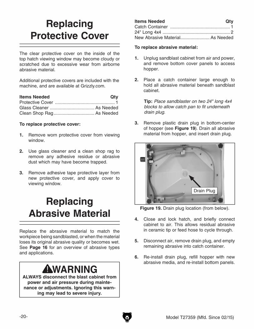
3. Remove plastic drain plug in bottom-center of hopper (see Figure 19). Drain all abrasive material from hopper, and insert drain plug.
Figure 19. Drain plug location (from below).
Drain Plug
4. Close and lock hatch, and briefly connect cabinet to air. This allows residual abrasive in ceramic tip or feed hose to cycle through.
5. Disconnect air, remove drain plug, and empty remaining abrasive into catch container.
6. Re-install drain plug, refill hopper with new abrasive media, and re-install bottom panels.
Model T27359 (Mfd. Since 02/15) -21-
SHOCK HAZARD. Working on wiring that is con-nected to a power source is extremely dangerous. Touching electrified parts will result in personal injury including but not limited to severe burns, electrocution, or death. Disconnect the power from the machine before servicing electrical com-ponents!
MODIFICATIONS. Modifying the wiring beyond what is shown in the diagram may lead to unpre-dictable results, including serious injury or fire. This includes the installation of unapproved after-market parts.
WIRE CONNECTIONS. All connections must be tight to prevent wires from loosening during machine operation. Double-check all wires dis-connected or connected during any wiring task to ensure tight connections.
CIRCUIT REQUIREMENTS. You MUST follow the requirements at the beginning of this manualwhen connecting your machine to a power source.
WIRE/COMPONENT DAMAGE. Damaged wires or components increase the risk of serious per-sonal injury, fire, or machine damage. If you notice that any wires or components are damaged while performing a wiring task, replace those wires or components.
MOTOR WIRING. The motor wiring shown inthese diagrams is current at the time of printingbut may not match your machine. If you find thisto be the case, use the wiring diagram inside the motor junction box.
CAPACITORS/INVERTERS. Some capacitorsand power inverters store an electrical charge for up to 10 minutes after being disconnected from the power source. To reduce the risk of being shocked, wait at least this long before working on capacitors.
EXPERIENCING DIFFICULTIES. If you are expe-riencing difficulties understanding the information included in this section, contact our Technical Support at (570) 546-9663.
Wiring Safety Instructions
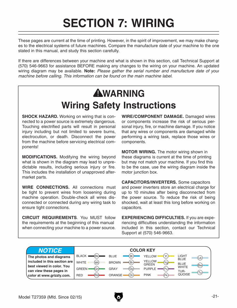
The photos and diagrams included in this section are best viewed in color. You can view these pages in color at www.grizzly.com.
These pages are current at the time of printing. However, in the spirit of improvement, we may make chang-es to the electrical systems of future machines. Compare the manufacture date of your machine to the one stated in this manual, and study this section carefully.
If there are differences between your machine and what is shown in this section, call Technical Support at (570) 546-9663 for assistance BEFORE making any changes to the wiring on your machine. An updated wiring diagram may be available. Note: Please gather the serial number and manufacture date of your machine before calling. This information can be found on the main machine label.
SECTION 7: WIRINGmachine

-22- Model T27359 (Mfd. Since 02/15)READ ELECTRICAL SAFETY ON PAGE 21!
Wiring Diagram
ON/OFF Switch KCD4
(viewed from behind)
Transformer Receptacle
(viewed from behind)
LED Light12VDCLED
Connector
TransformerConnector
120 VACClass 2 Transformer
with 15A Plug
DC
12V-01
174128*28
7
25A 250V
TransformerClass 2
In: 120VACOut: 12VDC 700mAModel: 41-12-700
EIA 3639828D
Sandblast Cabinet(viewed from above)
Figure 20. Transformer.
Figure 21. ON/OFF switch and transformer receptacle wiring.
Receptacle Switch
Figure 22. Transformer receptacle.
Receptacle
Figure 23. LED light.
LED

Model T27359 (Mfd. Since 02/15) -23-READ ELECTRICAL SAFETY ON PAGE 21!
Air System Diagram
Air SupplyIn
(To Blast Gun)
Sandblast Cabinet(viewed from below)
Foot Pedal Air ControlSTNC
Model: TG23-J-08Supply Press
0~0.8MPa
INOUT
Pressure Gauge
WARNING!DISCONNECT POWER AND AIR SUPPLY BEFORE ADJUSTMENTS, MAINTENANCE, OR SERVICE.
RegulatorAR-2000
Max Press: 9.9 Kgf/cm²Air Range: 0.5–9.0 Kgf/cm²
Figure 26. Air jet/ceramic tip.
Figure 25. Pressure gauge.
Figure 28. Foot Pedal.
Figure 27. Regulator.
Figure 24. Air system (viewed from below).
MainAir In
Pressure Gauge
Regulator
ToFootPedal
FromFootPedal
ToBlastGun

-24- Model T27359 (Mfd. Since 02/15)
21
37
44
43
14
2
13
5
4
3
1
15
16
18 19
17
20
12
6
89
7
11 10
4
23
22
31
32
33
34
38
41
42
39
40
3536
45
4847
4953 52
5150
46
2528
26
27
29
3024
48
59
5556
58
55
56
55
56
57
5457
6061
62
1963
32
55 56
59
58
56
51
5657
57
56
38
Main
SECTION 8: PARTSWe do our best to stock replacement parts when possible, but we cannot guarantee that all parts shown are available for purchase. Call (800) 523-4777 or visit www.grizzly.com/parts to check for availability.
We do our best to stock replacement parts when possible, but we cannot guarantee that all parts shown are available for purchase. Call (800) 523-4777 or visit www.grizzly.com/parts to check for availability.

Model T27359 (Mfd. Since 02/15) -25-
REF PART # DESCRIPTION REF PART # DESCRIPTION1 PT27359001 WINDOW FRAME 33 PT27359033 NOZZLE BODY2 PT27359002 WINDOW GLASS 34 PT27359034 AIR JET (BRASS) 3 PT27359003 INNER HATCH PLATE 35 PT27359035 RUBBER GASKET4 PT27359004 FOAM GASKET 36 PT27359036 NOZZLE EXTENSION (BRASS)5 PT27359005 CLEAR PROTECTIVE FILM 2-PC 37 PT27359037 NOZZLE SEAT6 PT27359006 POWER CORD 18G 2W 72" 1-15P 38 PT27359038 COMPRESSION FITTING 16MM (BRASS)7 PT27359007 POWER CORD RECEIVER 39 PT27359039 ABRASIVE HOSE 16 OD X 300MM L8 PT27359008 SWITCH BOX 40 PT27359040 FLEXIBLE HOSE 8 OD X 350MM L9 PT27359009 ON/OFF TOGGLE SWITCH KCD4 15A 250V 41 PT27359041 THREADED MUFFLER 3/8-27 X 4410 PT27359010 LED LIGHT BRACKET 42 PT27359042 FOOT PEDAL STNC TG23-J-0811 PT27359011 LED LIGHT 12V DC 43 PT27359043 PRESSURE REGULATOR XXPC AR-200012 PT27359012 STRAIN RELIEF PG-9 TYPE-3 44 PT27359044 FLEXIBLE HOSE 8 OD X 1400MM L (RED)13 PT27359013 LATCH 45 PT27359045 FLEXIBLE HOSE 8 OD X 1400MM L (BLUE)14 PT27359014 TOP HATCH HINGE 46 PT27359046 AIR FITTING 1/8" NPT STRAIGHT15 PT27359015 CABINET 47 PT27359047 AIR FITTING 1/8" NPT STRAIGHT 16 PT27359016 FILTER RING, METAL 48 PT27359048 FLAT WASHER 3/817 PT27359017 FILTER ELEMENT 49 PT27359049 AIR FITTING 1/8" NPT 90-DEG18 PT27359018 GLOVE (RIGHT) 50 PT27359050 AIR FITTING 1/8" NPT STRAIGHT19 PT27359019 PLASTIC ZIP TIE 51 PT27359051 AIR FITTING 1/4" NPT STRAIGHT 20 PT27359020 BLAST NOZZLE 3.5MM ID 52 PT27359052 AIR FITTING 1/8" NPT 90-DEG21 PT27359021 TOP HATCH SEAL 53 PT27359053 AIR FITTING 1/4" NPT 90-DEG22 PT27359022 BOTTOM SCREEN (REAR) 54 PT27359054 LOCK WASHER 4MM23 PT27359023 BOTTOM SCREEN (FRONT) 55 PT27359055 FLAT WASHER 4MM24 PT27359024 AIR HOSE CLIP, METAL 56 PT27359056 HEX NUT M4-.725 PT27359025 PHLP HD SCR M6-1 X 12 57 PT27359057 PHLP HD SCR M4-.7 X 826 PT27359026 AIR PRESSURE GAUGE 58 PT27359058 PHLP HD SCR M4-.7 X 1627 PT27359027 HOPPER PLUG, 30 X 12MM PLASTIC 59 PT27359059 PHLP HD SCR M4-.7 X 1228 PT27359028 AIR LINE INLET 60 PT27359060 FLEXIBLE HOSE 8 OD X 200MM L (BLUE)29 PT27359029 FOOT PAD M6-1 X 12 61 PT27359061 FLEXIBLE HOSE 8 OD X 140MM L (RED)30 PT27359030 HOPPER 62 PT27359062 FLEXIBLE HOSE 8 OD X 600MM L (RED)31 PT27359031 BLAST NOZZLE M16-1.5 BRASS 63 PT27359063 GLOVE (LEFT)32 PT27359032 GLOVE SEAT
Main Parts List

-26- Model T27359 (Mfd. Since 02/15)
Safety labels help reduce the risk of serious injury caused by machine hazards. If any label comes off or becomes unreadable, the owner of this machine MUST replace it in the original location before resuming operations. For replacements, contact (800) 523-4777 or www.grizzly.com.
Labels & Cosmetics
101 102
103104105106
107
108
REF PART # DESCRIPTION REF PART # DESCRIPTION101 PT27359101 ELECTRICITY LABEL 105 PT27359105 GLASSES/RESPIRATOR LABEL102 PT27359102 TOUCH-UP PAINT, GRIZZLY BEIGE 106 PT27359106 READ MANUAL LABEL103 PT27359103 BLAST INJURY LABEL 107 PT27359107 MACHINE ID LABEL104 PT27359104 PSI LABEL 120 MAX 108 PT27359108 SANDBLAST HAZARDS LABEL

CU
T A
LON
G D
OT
TE
D L
INE
Name _____________________________________________________________________________
Street _____________________________________________________________________________
City _______________________ State _________________________ Zip _____________________
Phone # ____________________ Email _________________________________________________
Model # ____________________ Order # _______________________ Serial # __________________
WARRANTY CARD
The following information is given on a voluntary basis. It will be used for marketing purposes to help us develop better products and services. Of course, all information is strictly confidential.
1. How did you learn about us? ____ Advertisement ____ Friend ____ Catalog ____ Card Deck ____ Website ____ Other:
2. Which of the following magazines do you subscribe to?
3. What is your annual household income? ____ $20,000-$29,000 ____ $30,000-$39,000 ____ $40,000-$49,000 ____ $50,000-$59,000 ____ $60,000-$69,000 ____ $70,000+
4. What is your age group? ____ 20-29 ____ 30-39 ____ 40-49 ____ 50-59 ____ 60-69 ____ 70+
5. How long have you been a woodworker/metalworker? ____ 0-2 Years ____ 2-8 Years ____ 8-20 Years ____20+ Years
6. How many of your machines or tools are Grizzly? ____ 0-2 ____ 3-5 ____ 6-9 ____10+
7. Do you think your machine represents a good value? _____Yes _____No
8. Would you recommend Grizzly Industrial to a friend? _____Yes _____No
9. Would you allow us to use your name as a reference for Grizzly customers in your area? Note: We never use names more than 3 times. _____Yes _____No
10. Comments: _____________________________________________________________________
_________________________________________________________________________________
_________________________________________________________________________________
_________________________________________________________________________________
____ Cabinetmaker & FDM____ Family Handyman____ Hand Loader____ Handy____ Home Shop Machinist____ Journal of Light Cont.____ Live Steam____ Model Airplane News____ Old House Journal____ Popular Mechanics
____ Popular Science____ Popular Woodworking____ Precision Shooter____ Projects in Metal____ RC Modeler____ Rifle____ Shop Notes____ Shotgun News____ Today’s Homeowner____ Wood
____ Wooden Boat____ Woodshop News____ Woodsmith____ Woodwork____ Woodworker West____ Woodworker’s Journal____ Other:

TAPE ALONG EDGES--PLEASE DO NOT STAPLE
FOLD ALONG DOTTED LINE
FOLD ALONG DOTTED LINE
GRIZZLY INDUSTRIAL, INC.P.O. BOX 2069BELLINGHAM, WA 98227-2069
PlaceStampHere
Name_______________________________
Street_______________________________
City______________State______Zip______
Send a Grizzly Catalog to a friend:

WARRANTY & RETURNSGrizzly Industrial, Inc. warrants every product it sells for a period of 1 year to the original purchaser from the date of purchase. This warranty does not apply to defects due directly or indirectly to misuse, abuse, negligence, accidents, repairs or alterations or lack of maintenance. This is Grizzly’s sole written warranty and any and all warranties that may be implied by law, including any merchantability or fitness, for any par-ticular purpose, are hereby limited to the duration of this written warranty. We do not warrant or represent that the merchandise complies with the provisions of any law or acts unless the manufacturer so warrants. In no event shall Grizzly’s liability under this warranty exceed the purchase price paid for the product and any legal actions brought against Grizzly shall be tried in the State of Washington, County of Whatcom.
We shall in no event be liable for death, injuries to persons or property or for incidental, contingent, special, or consequential damages arising from the use of our products.
To take advantage of this warranty, contact us by mail or phone and give us all the details. We will then issue you a “Return Number,’’ which must be clearly posted on the outside as well as the inside of the carton. We will not accept any item back without this number. Proof of purchase must accompany the merchandise.
The manufacturers reserve the right to change specifications at any time because they constantly strive to achieve better quality equipment. We make every effort to ensure that our products meet high quality and durability standards and we hope you never need to use this warranty.
Please feel free to write or call us if you have any questions about the machine or the manual.
Thank you again for your business and continued support. We hope to serve you again soon.