
MODEL T10050 RIGHT ANGLE IRON BENDER - Grizzlycdn0.grizzly.com/manuals/t10050_m.pdf · MODEL T10050...
8
Inventory (Figure 2) A. Bender (not shown) .................................... 1 B. Bender Handle ........................................... 1 C. Work Stop Rod ........................................... 1 D. Hex Bolts M10-1.5 x 40 (Handle) ............... 2 E. Flat Washers 10mm (Handle) .................... 2 F. Work Stop................................................... 1 G. Work Stop Knob ......................................... 1 H. Hex Nut M12-1.75 (Work Stop Rod) .......... 1 Specifications Maximum Workpiece Thickness........ 3 Ga.( 15 ⁄64") Maximum Workpiece Width.............................. 4" Machine Weight .........................................81 lbs. MODEL T10050 RIGHT ANGLE IRON BENDER INSTRUCTIONS Figure 1. Model T10050. Damage to your eyes, face, and hands could result from using this item without proper protective gear, such as safety glasses or a face shield, and gloves. Copy RiGHT © July, 2008 By G Rizzly iNdu STRial, iNC. WARNING: NO PORTION OF THIS MANUAL MAY BE REPRODUCED IN ANY SHAPE OR FORM WITHOUT THE WRITTEN APPROVAL OF GRIZZLY INDUSTRIAL, INC. #JB10791 pRiNTed i N CHiNa Figure 2. inventory. If you need help with your new machine, call our Tech Support at: (570) 546-9663. B C d e F G H
Transcript of MODEL T10050 RIGHT ANGLE IRON BENDER - Grizzlycdn0.grizzly.com/manuals/t10050_m.pdf · MODEL T10050...
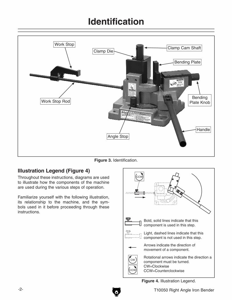
Inventory (Figure 2)A. Bender (not shown) .................................... 1B. Bender Handle ........................................... 1C. Work Stop Rod ........................................... 1D. Hex Bolts M10-1.5 x 40 (Handle) ............... 2E. Flat Washers 10mm (Handle) .................... 2F. Work Stop ................................................... 1G. Work Stop Knob ......................................... 1H. Hex Nut M12-1.75 (Work Stop Rod) .......... 1
SpecificationsMaximum Workpiece Thickness ........ 3 Ga.(15⁄64")Maximum Workpiece Width ..............................4"Machine Weight .........................................81 lbs.
MODEL T10050RIGHT ANGLE IRON BENDER
INSTRUCTIONS
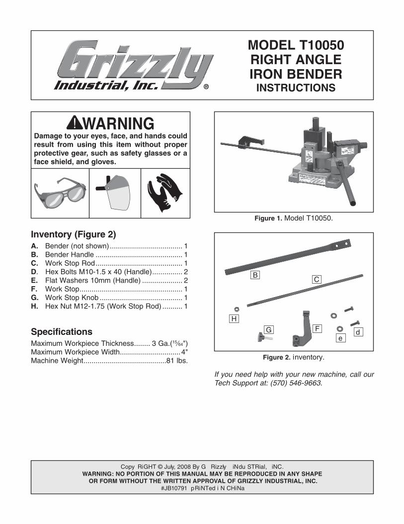
Figure 1. Model T10050.
Damage to your eyes, face, and hands could result from using this item without proper protective gear, such as safety glasses or a face shield, and gloves.
Copy RiGHT © July, 2008 By G Rizzly iNdu STRial, iNC.WARNING: NO PORTION OF THIS MANUAL MAY BE REPRODUCED IN ANY SHAPE
OR FORM WITHOUT THE WRITTEN APPROVAL OF GRIZZLY INDUSTRIAL, INC. #JB10791 pRiNTed i N CHiNa
Figure 2. inventory.
If you need help with your new machine, call our Tech Support at: (570) 546-9663.
BC
de
FG
H
-2- T10050 Right angle iron Bender
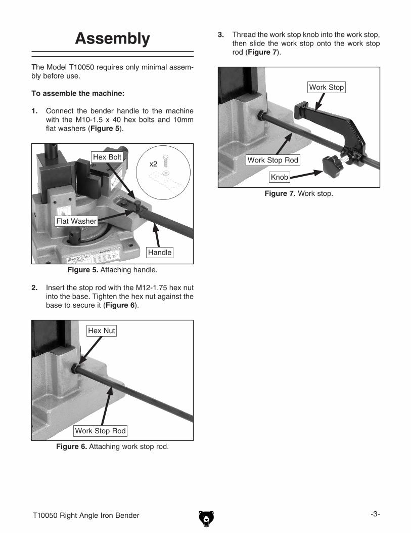
Figure 3.. identification.
Identification
Illustration Legend (Figure 4)Throughout these instructions, diagrams are used to illustrate how the components of the machine are used during the various steps of operation.
Familiarize yourself with the following illustration, its relationship to the machine, and the sym-bols used in it before proceeding through these instructions.
Figure 4.. Illustration Legend.
Work Stop Rod
Work Stop
Clamp die
Handle
Bending plate
Bending plate Knob
Clamp Cam Shaft
angle Stop
T10050 Right angle iron Bender -3-
Assembly
The Model T10050 requires only minimal assem-bly before use.
To assemble the machine:
1.. Connect the bender handle to the machine with the M10-1.5 x 40 hex bolts and 10mm flat washers (Figure 5).
Figure 5.. Attaching handle.
x2
Handle
Hex Bolt
Flat Washer
2.. insert the stop rod with the M12-1.75 hex nut into the base. Tighten the hex nut against the base to secure it (Figure 6).
Figure 6.. Attaching work stop rod.
Work Stop Rod
Hex Nut
3.. Thread the work stop knob into the work stop, then slide the work stop onto the work stop rod (Figure 7).
Figure 7.. Work stop.
Work Stop
Work Stop Rod
Knob
-4- T10050 Right angle iron Bender
Mounting Operations
once you have confirmed that your machine is assembled and functioning properly, mount it to a workbench through the holes in the base. Be sure the workbench will remain stable when bending force is applied to the machine. if necessary, anchor the workbench to a wall or the floor to provide the necessary stability.
The strongest mounting option is a "Through Mount" where holes are drilled all the way through the workbench, and hex bolts, washers, and hex nuts are used to secure the machine to the workbench.
Figure 8.. example of a through mount setup.
Figure 9.. example of a direct mount setup.
another option for mounting is a "direct Mount" where the machine is simply secured to the work-bench with a lag screw.
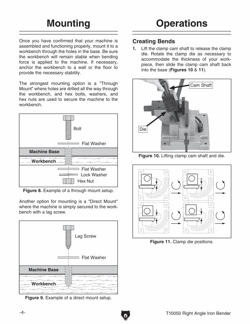
Creating Bends1.. lift the clamp cam shaft to release the clamp
die. Rotate the clamp die as necessary to accommodate the thickness of your work-piece, then slide the clamp cam shaft back into the base (Figures 10 & 11).
Figure 10.. Lifting clamp cam shaft and die.
Figure 11.. Clamp die positions.
Cam Shaft
die
T10050 Right angle iron Bender -5-
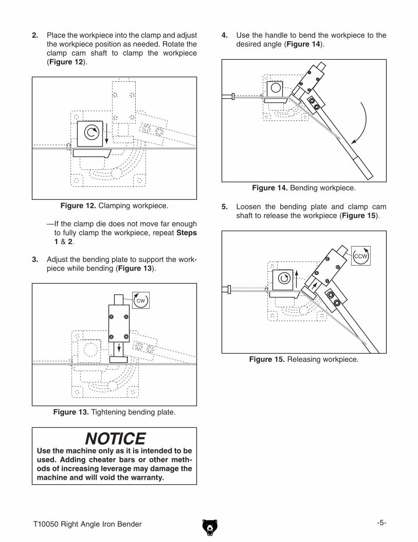
4.. use the handle to bend the workpiece to the desired angle (Figure 14).
2.. place the workpiece into the clamp and adjust the workpiece position as needed. Rotate the clamp cam shaft to clamp the workpiece (Figure 12).
Figure 12.. Clamping workpiece.
Figure 14.. Bending workpiece.
Figure 15.. Releasing workpiece.
—if the clamp die does not move far enough to fully clamp the workpiece, repeat Steps 1 & 2.
3.. adjust the bending plate to support the work-piece while bending (Figure 13).
Figure 13.. Tightening bending plate.
5.. loosen the bending plate and clamp cam shaft to release the workpiece (Figure 15).
NOTICEUse the machine only as it is intended to be used.. Adding cheater bars or other meth-ods of increasing leverage may damage the machine and will void the warranty..
-6- T10050 Right angle iron Bender
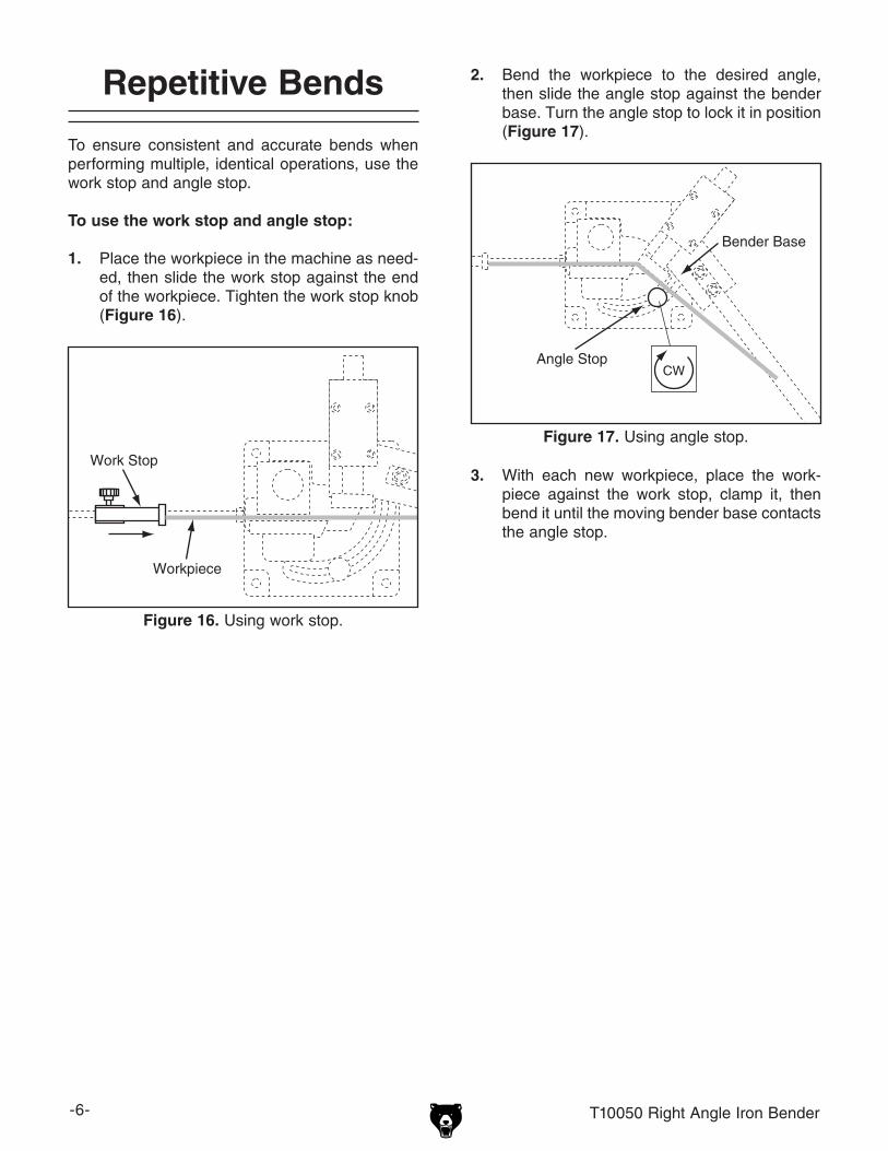
To ensure consistent and accurate bends when performing multiple, identical operations, use the work stop and angle stop.
To use the work stop and angle stop:
1.. place the workpiece in the machine as need-ed, then slide the work stop against the end of the workpiece. Tighten the work stop knob (Figure 16).
2.. Bend the workpiece to the desired angle, then slide the angle stop against the bender base. Turn the angle stop to lock it in position (Figure 17).
Figure 16.. Using work stop.
Figure 17.. Using angle stop.
3.. With each new workpiece, place the work-piece against the work stop, clamp it, then bend it until the moving bender base contacts the angle stop.
Repetitive Bends
T10050 Right angle iron Bender -7-
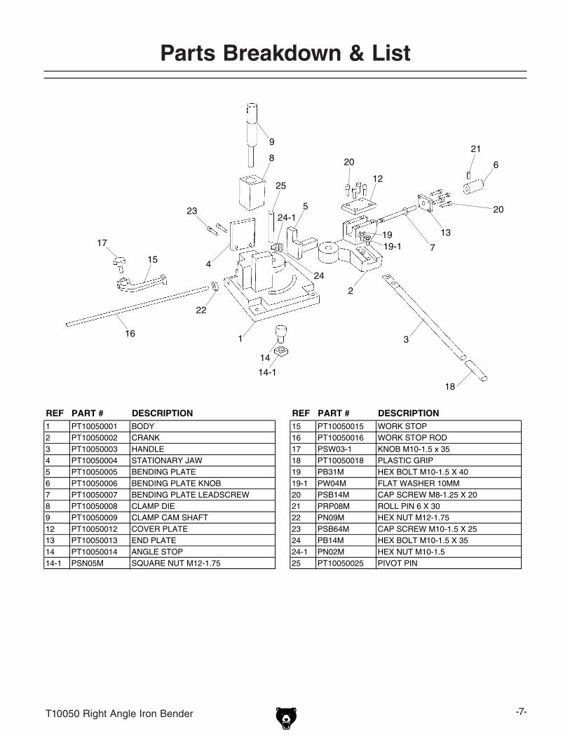
parts Breakdown & List
REF PART # DESCRIPTION REF PART # DESCRIPTION1 PT10050001 BODY 15 PT10050015 WORK STOP2 PT10050002 CRANK 16 PT10050016 WORK STOP ROD3 PT10050003 HANDLE 17 PSW03-1 KNOB M10-1.5 x 354 PT10050004 STATIONARY JAW 18 PT10050018 PLASTIC GRIP5 PT10050005 BENDING PLATE 19 PB31M HEX BOLT M10-1.5 X 406 PT10050006 BENDING PLATE KNOB 19-1 PW04M FLAT WASHER 10MM7 PT10050007 BENDING PLATE LEADSCREW 20 PSB14M CAP SCREW M8-1.25 X 208 PT10050008 CLAMP DIE 21 PRP08M ROLL PIN 6 X 309 PT10050009 CLAMP CAM SHAFT 22 PN09M HEX NUT M12-1.7512 PT10050012 COVER PLATE 23 PSB64M CAP SCREW M10-1.5 X 2513 PT10050013 END PLATE 24 PB14M HEX BOLT M10-1.5 X 3514 PT10050014 ANGLE STOP 24-1 PN02M HEX NUT M10-1.514-1 PSN05M SQUARE NUT M12-1.75 25 PT10050025 PIVOT PIN