
Polynomial Chaos based uncertainty propagation Intrusive and Non-Intrusive Methods

MODEL: Q8 SERIES
NON-INTRUSIVE CALIBRATION
GAS TRANSMITTER/SENSOR
INSTALLATION
OPERATION AND MAINTENANCE
MANUAL
AUTOMATION COMPONENTS, INC.
2305 PLEASANT VIEW ROAD | MIDDLETON, WI 53562
PHONE: (888) 967-5224 FAX: (608) 831-7407
Web: workaci.com
Q8 Operation And Maintenance Manual
86350-001-000 RB Oct. 03, 2017 1
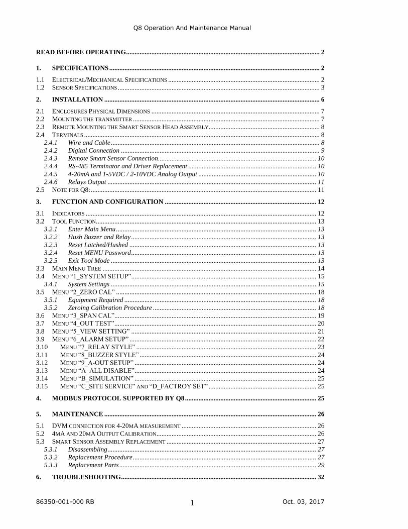
READ BEFORE OPERATING ................................................................................................................... 2
1. SPECIFICATIONS ............................................................................................................................. 2
1.1 ELECTRICAL/MECHANICAL SPECIFICATIONS .......................................................................................... 2 1.2 SENSOR SPECIFICATIONS ........................................................................................................................ 3
2. INSTALLATION ................................................................................................................................ 6
2.1 ENCLOSURES PHYSICAL DIMENSIONS .................................................................................................... 7 2.2 MOUNTING THE TRANSMITTER ............................................................................................................... 7 2.3 REMOTE MOUNTING THE SMART SENSOR HEAD ASSEMBLY.................................................................. 8 2.4 TERMINALS ............................................................................................................................................ 8
2.4.1 Wire and Cable ............................................................................................................................ 8 2.4.2 Digital Connection ...................................................................................................................... 9 2.4.3 Remote Smart Sensor Connection.............................................................................................. 10 2.4.4 RS-485 Terminator and Driver Replacement ............................................................................ 10 2.4.5 4-20mA and 1-5VDC / 2-10VDC Analog Output ...................................................................... 10 2.4.6 Relays Output ............................................................................................................................ 11
2.5 NOTE FOR Q8: ...................................................................................................................................... 11
3. FUNCTION AND CONFIGURATION .......................................................................................... 12
3.1 INDICATORS ......................................................................................................................................... 12 3.2 TOOL FUNCTION................................................................................................................................... 13
3.2.1 Enter Main Menu ....................................................................................................................... 13 3.2.2 Hush Buzzer and Relay .............................................................................................................. 13 3.2.3 Reset Latched/Hushed ............................................................................................................... 13 3.2.4 Reset MENU Password .............................................................................................................. 13 3.2.5 Exit Tool Mode .......................................................................................................................... 13
3.3 MAIN MENU TREE ............................................................................................................................... 14 3.4 MENU “1_SYSTEM SETUP” .............................................................................................................. 15
3.4.1 System Settings .......................................................................................................................... 15 3.5 MENU “2_ZERO CAL” ....................................................................................................................... 18
3.5.1 Equipment Required .................................................................................................................. 18 3.5.2 Zeroing Calibration Procedure ................................................................................................. 18
3.6 MENU “3_SPAN CAL”........................................................................................................................ 19 3.7 MENU “4_OUT TEST” ........................................................................................................................ 20 3.8 MENU “5_VIEW SETTING” .............................................................................................................. 21 3.9 MENU “6_ALARM SETUP” ............................................................................................................... 22 3.10 MENU “7_RELAY STYLE” ........................................................................................................... 23 3.11 MENU “8_BUZZER STYLE” ......................................................................................................... 24 3.12 MENU “9_A-OUT SETUP” ............................................................................................................ 24 3.13 MENU “A_ALL DISABLE” ............................................................................................................ 24 3.14 MENU “B_SIMULATION” ............................................................................................................ 25 3.15 MENU “C_SITE SERVICE” AND “D_FACTROY SET” ................................................................ 25
4. MODBUS PROTOCOL SUPPORTED BY Q8 .............................................................................. 25
5. MAINTENANCE .............................................................................................................................. 26
5.1 DVM CONNECTION FOR 4-20MA MEASUREMENT ................................................................................ 26 5.2 4MA AND 20MA OUTPUT CALIBRATION ............................................................................................... 26 5.3 SMART SENSOR ASSEMBLY REPLACEMENT ......................................................................................... 27
5.3.1 Disassembling ............................................................................................................................ 27 5.3.2 Replacement Procedure ............................................................................................................. 27 5.3.3 Replacement Parts ..................................................................................................................... 29
6. TROUBLESHOOTING .................................................................................................................... 32
Q8 Operation And Maintenance Manual
86350-001-000 RB Oct. 03, 2017 2
READ BEFORE OPERATING
All individuals who have or will have the responsibility of using, maintaining, or servicing this
product must carefully read this manual. The product will perform as designed only if it is used,
maintained, and serviced in accordance with the manufacturer’s instructions.
The Q8 is a state-of-the-art transmitter that can operate as an independent, stand-alone system or
as part of an integrated system. The Q8 connects with analog and digital signals to virtually any
controller, PLC, or DCS. Setup procedures are simplified with user-friendly push buttons and
LCD menus.
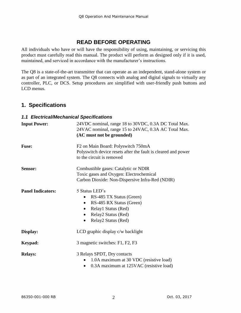
1. Specifications
1.1 Electrical/Mechanical Specifications
Input Power: 24VDC nominal, range 18 to 30VDC, 0.3A DC Total Max.
24VAC nominal, range 15 to 24VAC, 0.3A AC Total Max.
(AC must not be grounded)
Fuse: F2 on Main Board: Polyswitch 750mA
Polyswitch device resets after the fault is cleared and power
to the circuit is removed
Sensor: Combustible gases: Catalytic or NDIR
Toxic gases and Oxygen: Electrochemical
Carbon Dioxide: Non-Dispersive Infra-Red (NDIR)
Panel Indicators: 5 Status LED’s
• RS-485 TX Status (Green)
• RS-485 RX Status (Green)
• Relay1 Status (Red)
• Relay2 Status (Red)
• Relay2 Status (Red)
Display: LCD graphic display c/w backlight
Keypad: 3 magnetic switches: F1, F2, F3
Relays: 3 Relays SPDT, Dry contacts
• 1.0A maximum at 30 VDC (resistive load)
• 0.3A maximum at 125VAC (resistive load)
Q8 Operation And Maintenance Manual
86350-001-000 RB Oct. 03, 2017 3
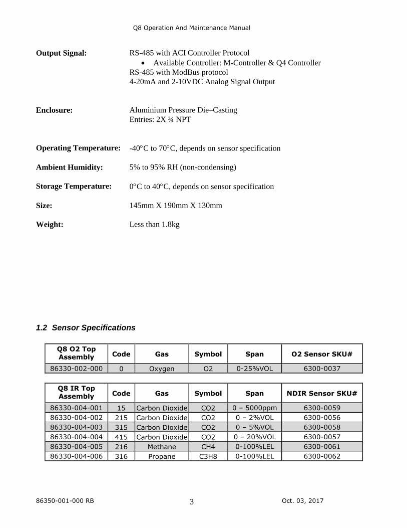
Output Signal: RS-485 with ACI Controller Protocol
• Available Controller: M-Controller & Q4 Controller
RS-485 with ModBus protocol
4-20mA and 2-10VDC Analog Signal Output
Enclosure: Aluminium Pressure Die–Casting
Entries: 2X ¾ NPT
Operating Temperature: -40C to 70C, depends on sensor specification
Ambient Humidity: 5% to 95% RH (non-condensing)
Storage Temperature: 0C to 40C, depends on sensor specification
Size: 145mm X 190mm X 130mm
Weight: Less than 1.8kg
1.2 Sensor Specifications
Q8 O2 Top Assembly Code Gas Symbol Span O2 Sensor SKU#
86330-002-000 0 Oxygen O2 0-25%VOL 6300-0037
Q8 IR Top Assembly Code Gas Symbol Span NDIR Sensor SKU#
86330-004-001 15 Carbon Dioxide CO2 0 – 5000ppm 6300-0059
86330-004-002 215 Carbon Dioxide CO2 0 – 2%VOL 6300-0056
86330-004-003 315 Carbon Dioxide CO2 0 – 5%VOL 6300-0058
86330-004-004 415 Carbon Dioxide CO2 0 – 20%VOL 6300-0057
86330-004-005 216 Methane CH4 0-100%LEL 6300-0061
86330-004-006 316 Propane C3H8 0-100%LEL 6300-0062
Q8 Operation And Maintenance Manual
86350-001-000 RB Oct. 03, 2017 4
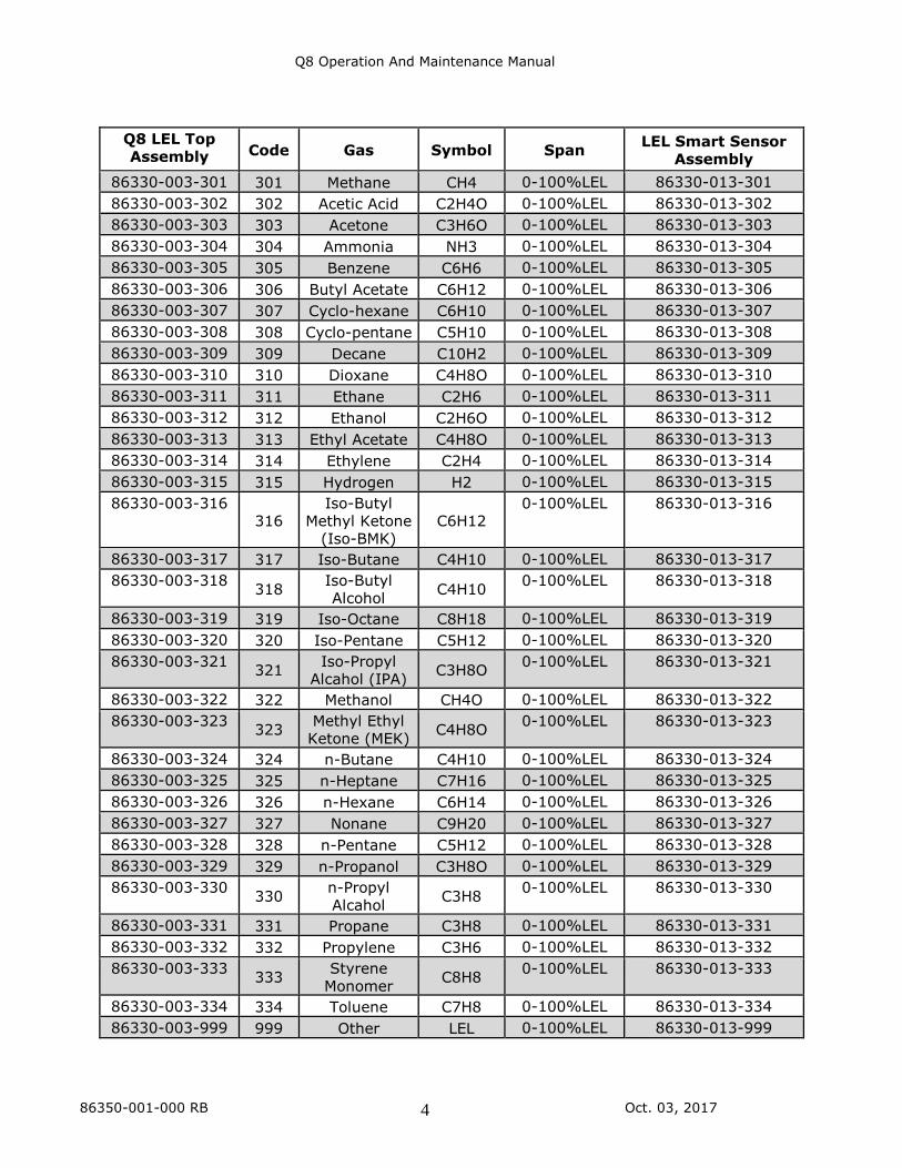
Q8 LEL Top Assembly Code Gas Symbol Span
LEL Smart Sensor Assembly
86330-003-301 301 Methane CH4 0-100%LEL 86330-013-301
86330-003-302 302 Acetic Acid C2H4O 0-100%LEL 86330-013-302
86330-003-303 303 Acetone C3H6O 0-100%LEL 86330-013-303
86330-003-304 304 Ammonia NH3 0-100%LEL 86330-013-304
86330-003-305 305 Benzene C6H6 0-100%LEL 86330-013-305
86330-003-306 306 Butyl Acetate C6H12 0-100%LEL 86330-013-306
86330-003-307 307 Cyclo-hexane C6H10 0-100%LEL 86330-013-307
86330-003-308 308 Cyclo-pentane C5H10 0-100%LEL 86330-013-308
86330-003-309 309 Decane C10H2 0-100%LEL 86330-013-309
86330-003-310 310 Dioxane C4H8O 0-100%LEL 86330-013-310
86330-003-311 311 Ethane C2H6 0-100%LEL 86330-013-311
86330-003-312 312 Ethanol C2H6O 0-100%LEL 86330-013-312
86330-003-313 313 Ethyl Acetate C4H8O 0-100%LEL 86330-013-313
86330-003-314 314 Ethylene C2H4 0-100%LEL 86330-013-314
86330-003-315 315 Hydrogen H2 0-100%LEL 86330-013-315
86330-003-316 316
Iso-Butyl Methyl Ketone
(Iso-BMK) C6H12
0-100%LEL 86330-013-316
86330-003-317 317 Iso-Butane C4H10 0-100%LEL 86330-013-317
86330-003-318 318
Iso-Butyl Alcohol
C4H10 0-100%LEL 86330-013-318
86330-003-319 319 Iso-Octane C8H18 0-100%LEL 86330-013-319
86330-003-320 320 Iso-Pentane C5H12 0-100%LEL 86330-013-320
86330-003-321 321
Iso-Propyl Alcahol (IPA)
C3H8O 0-100%LEL 86330-013-321
86330-003-322 322 Methanol CH4O 0-100%LEL 86330-013-322
86330-003-323 323
Methyl Ethyl Ketone (MEK)
C4H8O 0-100%LEL 86330-013-323
86330-003-324 324 n-Butane C4H10 0-100%LEL 86330-013-324
86330-003-325 325 n-Heptane C7H16 0-100%LEL 86330-013-325
86330-003-326 326 n-Hexane C6H14 0-100%LEL 86330-013-326
86330-003-327 327 Nonane C9H20 0-100%LEL 86330-013-327
86330-003-328 328 n-Pentane C5H12 0-100%LEL 86330-013-328
86330-003-329 329 n-Propanol C3H8O 0-100%LEL 86330-013-329
86330-003-330 330
n-Propyl Alcahol
C3H8 0-100%LEL 86330-013-330
86330-003-331 331 Propane C3H8 0-100%LEL 86330-013-331
86330-003-332 332 Propylene C3H6 0-100%LEL 86330-013-332
86330-003-333 333
Styrene Monomer
C8H8 0-100%LEL 86330-013-333
86330-003-334 334 Toluene C7H8 0-100%LEL 86330-013-334
86330-003-999 999 Other LEL 0-100%LEL 86330-013-999
Q8 Operation And Maintenance Manual
86350-001-000 RB Oct. 03, 2017 5
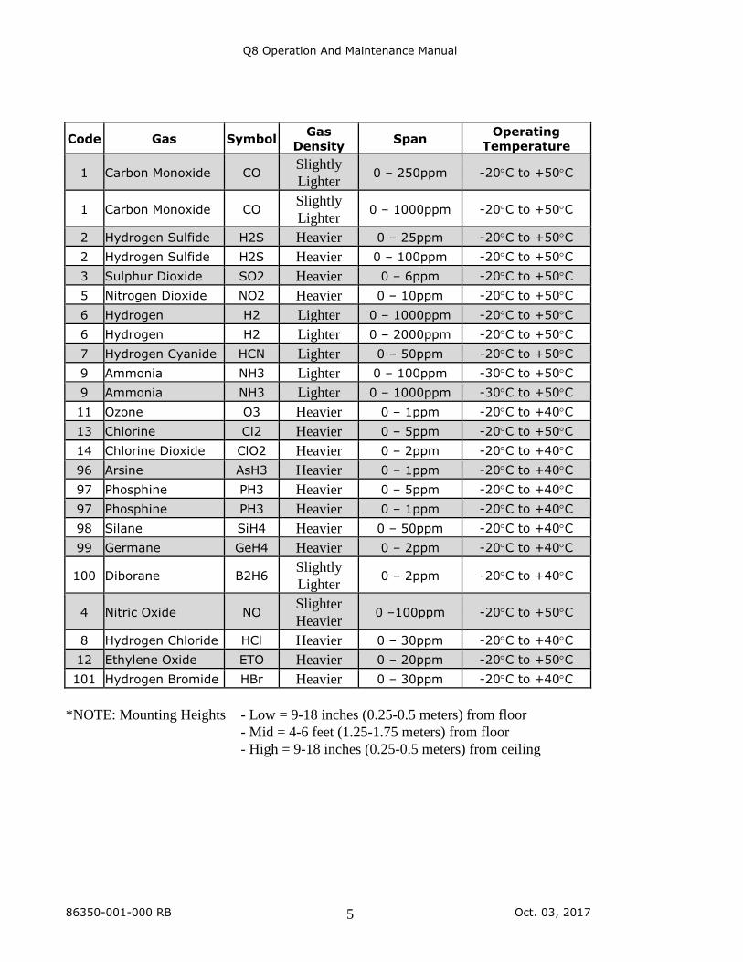
Code Gas Symbol Gas
Density Span
Operating Temperature
1 Carbon Monoxide CO Slightly
Lighter 0 – 250ppm -20C to +50C
1 Carbon Monoxide CO Slightly
Lighter 0 – 1000ppm -20C to +50C
2 Hydrogen Sulfide H2S Heavier 0 – 25ppm -20C to +50C
2 Hydrogen Sulfide H2S Heavier 0 – 100ppm -20C to +50C
3 Sulphur Dioxide SO2 Heavier 0 – 6ppm -20C to +50C
5 Nitrogen Dioxide NO2 Heavier 0 – 10ppm -20C to +50C
6 Hydrogen H2 Lighter 0 – 1000ppm -20C to +50C
6 Hydrogen H2 Lighter 0 – 2000ppm -20C to +50C
7 Hydrogen Cyanide HCN Lighter 0 – 50ppm -20C to +50C
9 Ammonia NH3 Lighter 0 – 100ppm -30C to +50C
9 Ammonia NH3 Lighter 0 – 1000ppm -30C to +50C
11 Ozone O3 Heavier 0 – 1ppm -20C to +40C
13 Chlorine Cl2 Heavier 0 – 5ppm -20C to +50C
14 Chlorine Dioxide ClO2 Heavier 0 – 2ppm -20C to +40C
96 Arsine AsH3 Heavier 0 – 1ppm -20C to +40C
97 Phosphine PH3 Heavier 0 – 5ppm -20C to +40C
97 Phosphine PH3 Heavier 0 – 1ppm -20C to +40C
98 Silane SiH4 Heavier 0 – 50ppm -20C to +40C
99 Germane GeH4 Heavier 0 – 2ppm -20C to +40C
100 Diborane B2H6 Slightly
Lighter 0 – 2ppm -20C to +40C
4 Nitric Oxide NO Slighter
Heavier 0 –100ppm -20C to +50C
8 Hydrogen Chloride HCl Heavier 0 – 30ppm -20C to +40C
12 Ethylene Oxide ETO Heavier 0 – 20ppm -20C to +50C
101 Hydrogen Bromide HBr Heavier 0 – 30ppm -20C to +40C
*NOTE: Mounting Heights - Low = 9-18 inches (0.25-0.5 meters) from floor
- Mid = 4-6 feet (1.25-1.75 meters) from floor
- High = 9-18 inches (0.25-0.5 meters) from ceiling
Q8 Operation And Maintenance Manual
86350-001-000 RB Oct. 03, 2017 6
2. Installation
Warnings:
Q8 is designed for installation and use in Zone 1 or 2 hazardous areas in many
countries including Europe and for Class 1 Division 1 or 2 area applications in
North America. Installation must be in accordance with the recognized standards
of the appropriate authority in the country concerned.
Access to the interior of the detector, when carrying out any work, must only be
conducted by trained personnel.
Before carrying out any work ensure local regulations and site procedures are
followed. Appropriate standards must be followed to maintain the overall
certification of the detector.
For installations where conduit is used, and the sensor is mounted directly to the
Q8, there must be a “Seal Fitting” installed for each of the cable gland entries
within 18 inches of the Q8. For installations where the smart sensor head assembly
will be mounted remotely from Q8, an additional “Seal Fittings” will be required:
One at each of the conduit entries for the power/signal/relay contact outputs and
one at the sensor wiring entrance. The total distance of the location of these Seal
Fittings is 18 inches. (e.g. If all 3 gland entries are to be used, 3 Seal Fittings should
be located, each within 6 inches of the wiring entrance).
If using an anti-seize compound, the threads should be thinly coated with an
approved silicone free compound e.g. petroleum jelly.
To reduce the risk of ignition of hazardous atmosphere, de-classify the area or
disconnect the equipment from the supply circuit before opening the detector
enclosure. Keep assembly tightly closed during operation.
Never attempt to open a junction box/enclosure or replace/refit the sensor in
potentially hazardous atmospheres while power is still applied to the transmitter.
The detector must be earthed/grounded for electrical safety and to limit the effects
of radio frequency interference. Earth/ground points are provided inside and
outside the unit. Ensure that all screens/instrument earth/clean earth wiring is
earthed/grounded at a single point (either at the controller or detector - BUT NOT
BOTH) to prevent false alarms due to earth/ground loops.
Take care when handling sensors as they may contain corrosive solutions.
This equipment is designed and constructed as to prevent ignition sources arising,
even in the event of frequent disturbances or equipment operating faults.
The sensor head must be fitted with the supplied weather protection, and mounted
so that the sinter is pointing downward to provide ingress protection IPX6.
Q8 Operation And Maintenance Manual
86350-001-000 RB Oct. 03, 2017 7
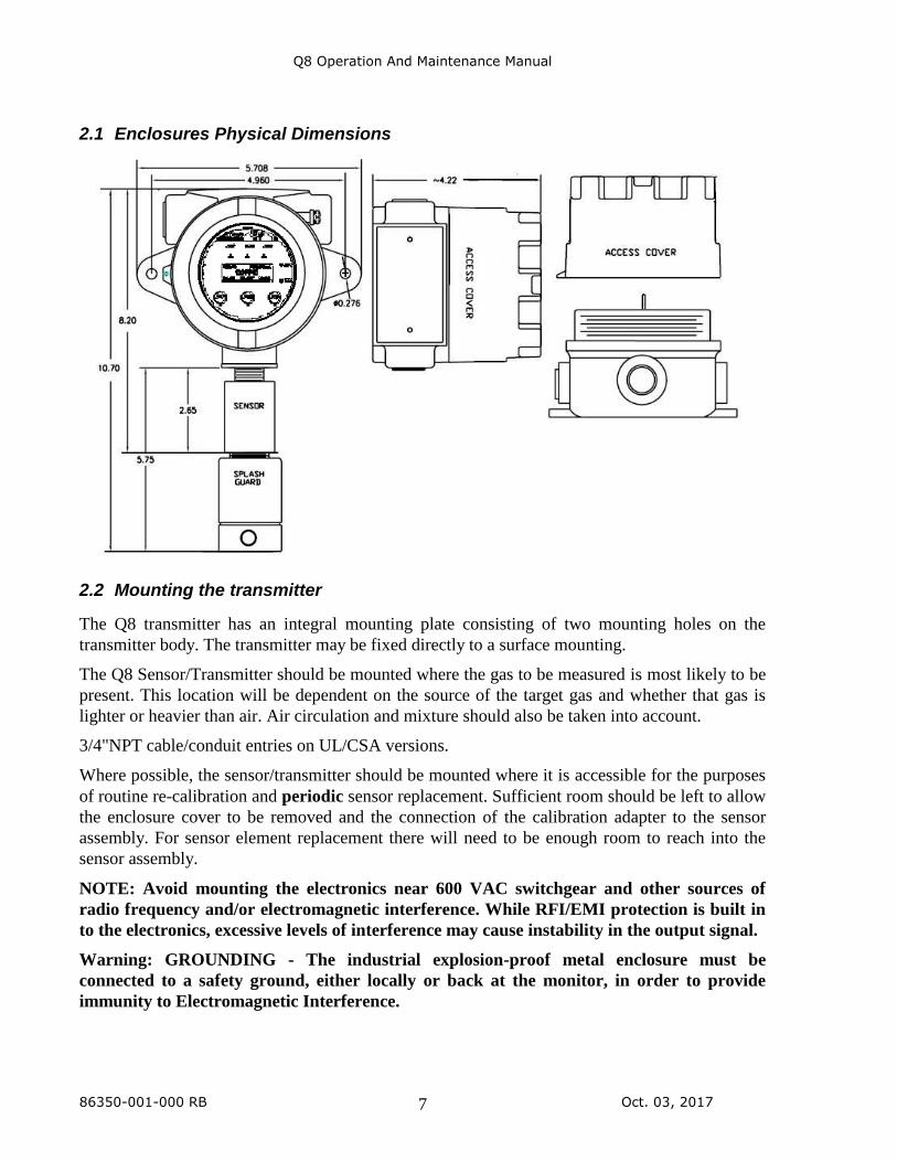
2.1 Enclosures Physical Dimensions
2.2 Mounting the transmitter
The Q8 transmitter has an integral mounting plate consisting of two mounting holes on the
transmitter body. The transmitter may be fixed directly to a surface mounting.
The Q8 Sensor/Transmitter should be mounted where the gas to be measured is most likely to be
present. This location will be dependent on the source of the target gas and whether that gas is
lighter or heavier than air. Air circulation and mixture should also be taken into account.
3/4"NPT cable/conduit entries on UL/CSA versions.
Where possible, the sensor/transmitter should be mounted where it is accessible for the purposes
of routine re-calibration and periodic sensor replacement. Sufficient room should be left to allow
the enclosure cover to be removed and the connection of the calibration adapter to the sensor
assembly. For sensor element replacement there will need to be enough room to reach into the
sensor assembly.
NOTE: Avoid mounting the electronics near 600 VAC switchgear and other sources of
radio frequency and/or electromagnetic interference. While RFI/EMI protection is built in
to the electronics, excessive levels of interference may cause instability in the output signal.
Warning: GROUNDING - The industrial explosion-proof metal enclosure must be
connected to a safety ground, either locally or back at the monitor, in order to provide
immunity to Electromagnetic Interference.
Q8 Operation And Maintenance Manual
86350-001-000 RB Oct. 03, 2017 8
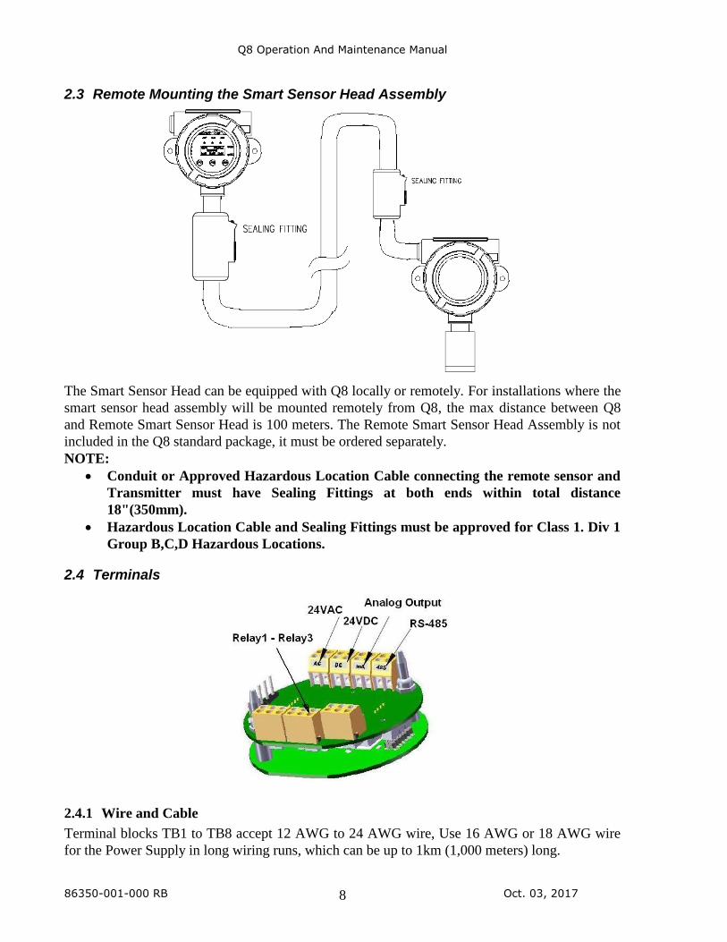
2.3 Remote Mounting the Smart Sensor Head Assembly
The Smart Sensor Head can be equipped with Q8 locally or remotely. For installations where the
smart sensor head assembly will be mounted remotely from Q8, the max distance between Q8
and Remote Smart Sensor Head is 100 meters. The Remote Smart Sensor Head Assembly is not
included in the Q8 standard package, it must be ordered separately.
NOTE:
• Conduit or Approved Hazardous Location Cable connecting the remote sensor and
Transmitter must have Sealing Fittings at both ends within total distance
18"(350mm).
• Hazardous Location Cable and Sealing Fittings must be approved for Class 1. Div 1
Group B,C,D Hazardous Locations.
2.4 Terminals
2.4.1 Wire and Cable
Terminal blocks TB1 to TB8 accept 12 AWG to 24 AWG wire, Use 16 AWG or 18 AWG wire
for the Power Supply in long wiring runs, which can be up to 1km (1,000 meters) long.
Q8 Operation And Maintenance Manual
86350-001-000 RB Oct. 03, 2017 9
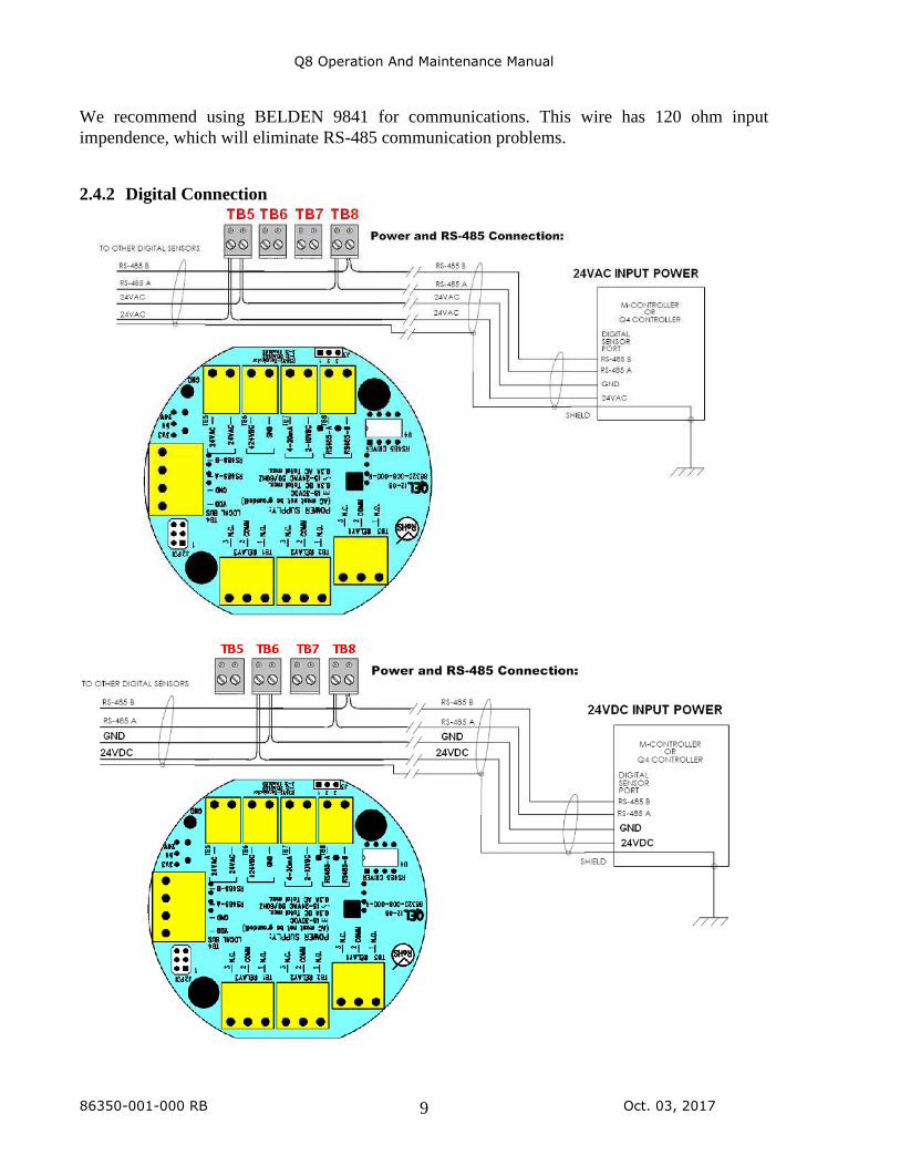
We recommend using BELDEN 9841 for communications. This wire has 120 ohm input
impendence, which will eliminate RS-485 communication problems.
2.4.2 Digital Connection
Q8 Operation And Maintenance Manual
86350-001-000 RB Oct. 03, 2017 10
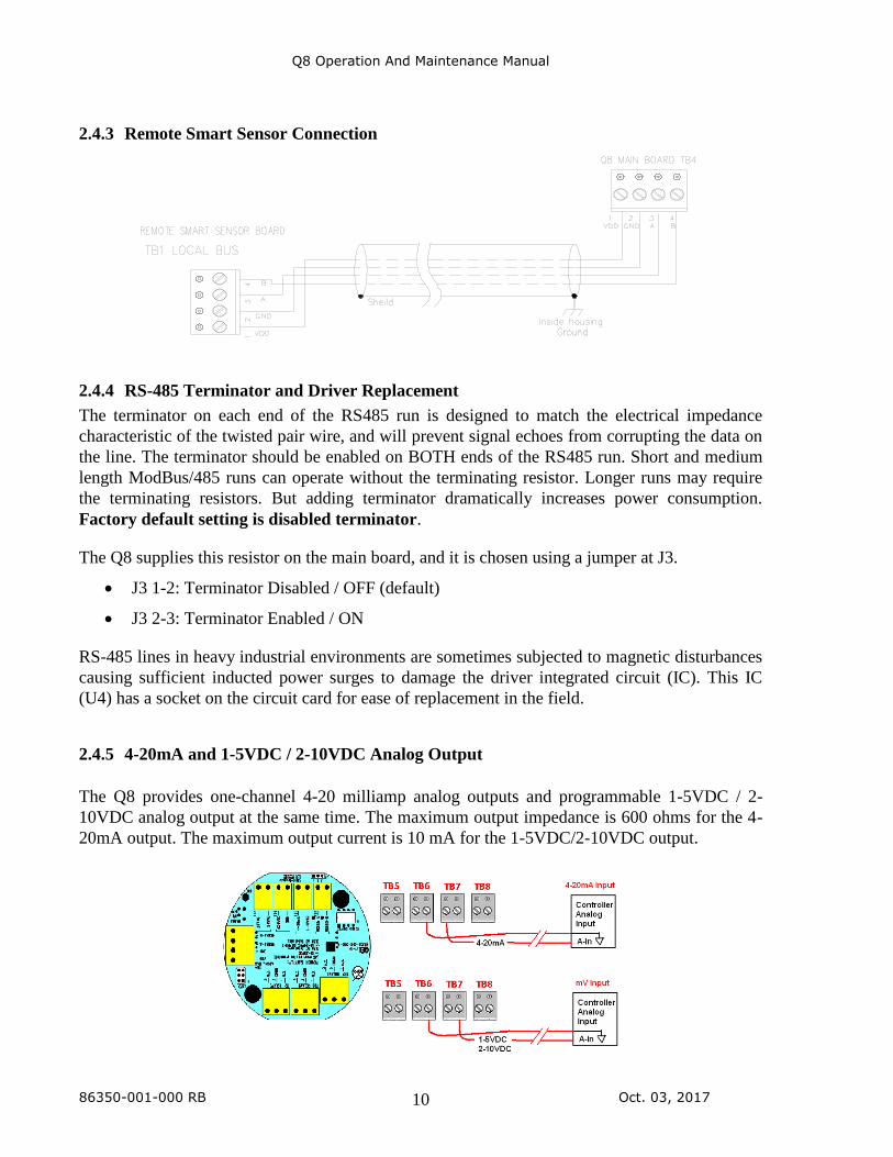
2.4.3 Remote Smart Sensor Connection
2.4.4 RS-485 Terminator and Driver Replacement
The terminator on each end of the RS485 run is designed to match the electrical impedance
characteristic of the twisted pair wire, and will prevent signal echoes from corrupting the data on
the line. The terminator should be enabled on BOTH ends of the RS485 run. Short and medium
length ModBus/485 runs can operate without the terminating resistor. Longer runs may require
the terminating resistors. But adding terminator dramatically increases power consumption.
Factory default setting is disabled terminator.
The Q8 supplies this resistor on the main board, and it is chosen using a jumper at J3.
• J3 1-2: Terminator Disabled / OFF (default)
• J3 2-3: Terminator Enabled / ON
RS-485 lines in heavy industrial environments are sometimes subjected to magnetic disturbances
causing sufficient inducted power surges to damage the driver integrated circuit (IC). This IC
(U4) has a socket on the circuit card for ease of replacement in the field.
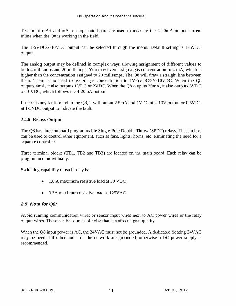
2.4.5 4-20mA and 1-5VDC / 2-10VDC Analog Output
The Q8 provides one-channel 4-20 milliamp analog outputs and programmable 1-5VDC / 2-
10VDC analog output at the same time. The maximum output impedance is 600 ohms for the 4-
20mA output. The maximum output current is 10 mA for the 1-5VDC/2-10VDC output.
Q8 Operation And Maintenance Manual
86350-001-000 RB Oct. 03, 2017 11
Test point mA+ and mA- on top plate board are used to measure the 4-20mA output current
inline when the Q8 is working in the field.
The 1-5VDC/2-10VDC output can be selected through the menu. Default setting is 1-5VDC
output.
The analog output may be defined in complex ways allowing assignment of different values to
both 4 milliamps and 20 milliamps. You may even assign a gas concentration to 4 mA, which is
higher than the concentration assigned to 20 milliamps. The Q8 will draw a straight line between
them. There is no need to assign gas concentration to 1V-5VDC/2V-10VDC. When the Q8
outputs 4mA, it also outputs 1VDC or 2VDC. When the Q8 outputs 20mA, it also outputs 5VDC
or 10VDC, which follows the 4-20mA output.
If there is any fault found in the Q8, it will output 2.5mA and 1VDC at 2-10V output or 0.5VDC
at 1-5VDC output to indicate the fault.
2.4.6 Relays Output
The Q8 has three onboard programmable Single-Pole Double-Throw (SPDT) relays. These relays
can be used to control other equipment, such as fans, lights, horns, etc. eliminating the need for a
separate controller.
Three terminal blocks (TB1, TB2 and TB3) are located on the main board. Each relay can be
programmed individually.
Switching capability of each relay is:
• 1.0 A maximum resistive load at 30 VDC
• 0.3A maximum resistive load at 125VAC
2.5 Note for Q8:
Avoid running communication wires or sensor input wires next to AC power wires or the relay
output wires. These can be sources of noise that can affect signal quality.
When the Q8 input power is AC, the 24VAC must not be grounded. A dedicated floating 24VAC
may be needed if other nodes on the network are grounded, otherwise a DC power supply is
recommended.
Q8 Operation And Maintenance Manual
86350-001-000 RB Oct. 03, 2017 12
3. Function and Configuration
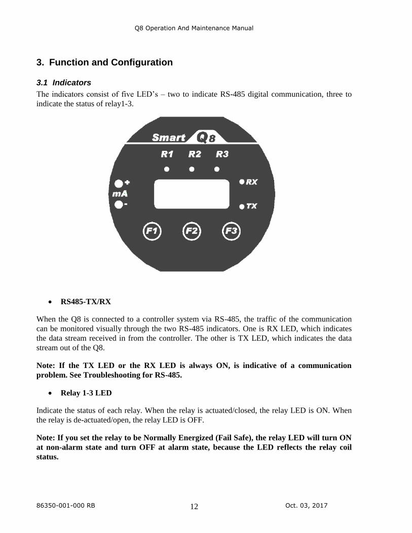
3.1 Indicators
The indicators consist of five LED’s – two to indicate RS-485 digital communication, three to
indicate the status of relay1-3.
• RS485-TX/RX
When the Q8 is connected to a controller system via RS-485, the traffic of the communication
can be monitored visually through the two RS-485 indicators. One is RX LED, which indicates
the data stream received in from the controller. The other is TX LED, which indicates the data
stream out of the Q8.
Note: If the TX LED or the RX LED is always ON, is indicative of a communication
problem. See Troubleshooting for RS-485.
• Relay 1-3 LED
Indicate the status of each relay. When the relay is actuated/closed, the relay LED is ON. When
the relay is de-actuated/open, the relay LED is OFF.
Note: If you set the relay to be Normally Energized (Fail Safe), the relay LED will turn ON
at non-alarm state and turn OFF at alarm state, because the LED reflects the relay coil
status.
Q8 Operation And Maintenance Manual
86350-001-000 RB Oct. 03, 2017 13
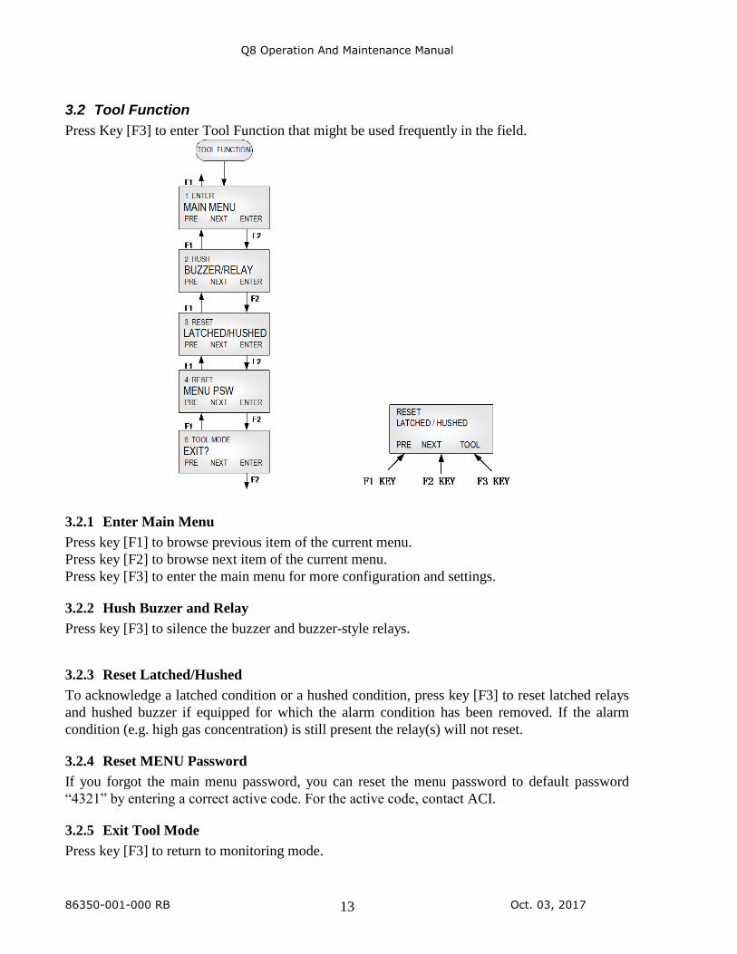
3.2 Tool Function
Press Key [F3] to enter Tool Function that might be used frequently in the field.
3.2.1 Enter Main Menu
Press key [F1] to browse previous item of the current menu.
Press key [F2] to browse next item of the current menu.
Press key [F3] to enter the main menu for more configuration and settings.
3.2.2 Hush Buzzer and Relay
Press key [F3] to silence the buzzer and buzzer-style relays.
3.2.3 Reset Latched/Hushed
To acknowledge a latched condition or a hushed condition, press key [F3] to reset latched relays
and hushed buzzer if equipped for which the alarm condition has been removed. If the alarm
condition (e.g. high gas concentration) is still present the relay(s) will not reset.
3.2.4 Reset MENU Password
If you forgot the main menu password, you can reset the menu password to default password
“4321” by entering a correct active code. For the active code, contact ACI.
3.2.5 Exit Tool Mode
Press key [F3] to return to monitoring mode.
Q8 Operation And Maintenance Manual
86350-001-000 RB Oct. 03, 2017 14
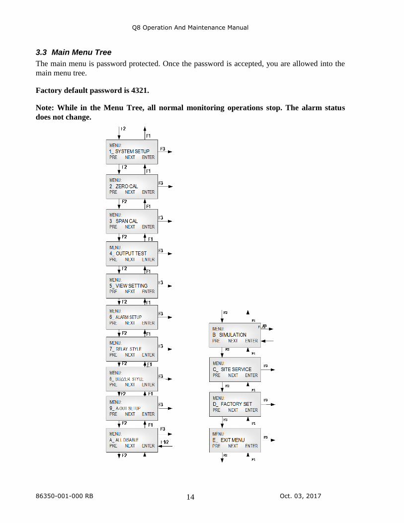
3.3 Main Menu Tree
The main menu is password protected. Once the password is accepted, you are allowed into the
main menu tree.
Factory default password is 4321.
Note: While in the Menu Tree, all normal monitoring operations stop. The alarm status
does not change.
Q8 Operation And Maintenance Manual
86350-001-000 RB Oct. 03, 2017 15
3.4 Menu “1_SYSTEM SETUP”
The system setup subdivision contains general settings for monitor operations, communications
and 4-20mA calibrations.
3.4.1 System Settings
Password: Default password is 4321.
Address:
M-Controllers support RS-485 addressing from 0 to 31 for digital sensors.
Q4 Controllers support RS-485 addressing from 0 to 3 for digital sensors.
The Q8 RS-485 address can be defined from 0 to 255. Default is 3.
Note: In ModBus protocol, the address 0 is for broadcast.
Baud rate: Define baud rate for RS-485 communication with ACI controller protocol,
ModBus protocol or BACnet protocol.
Q8 default baud rate is 4800 bps.
Scroll Rate: In normal operation, the sensor and relay status information scrolls
automatically. Set the number of seconds for each item to be displayed.
Default value is 3 seconds.
Backlight: The LCD backlight can be set to Always Off, Always On and Auto Power
Saving mode. In Auto Power Saving mode, the backlight will turn on for
10 seconds after any key has been pressed. Default setting is Auto mode.
4mA Cal
20mA Cal 1V
Cal 2V
Cal 5V
Cal 10V
Cal:
These values are established during factory calibration for the 4-20mA
analog output and should not require recalibration in the field. Do not
attempt to modify these settings in the field.
Changing these values will change the analog output signal scale.
Warning: This procedure is part of the factory setup. In most
circumstances it will not be necessary to perform this procedure in the
field. These functions require the use of precision reference
instrumentation.
New
Password:
The new password can be any combination of up to four digits. Default
password is 4321.
Warning: Be sure that you record the new password in a safe and
secure location!
Q8 Operation And Maintenance Manual
86350-001-000 RB Oct. 03, 2017 16
Protocol: When Q8 is connected to an M-Controller or a Q4-Controller, the protocol
should be set to OptoMux. The Q8 Default protocol is OptoMux.
The Q8 also supports ModBus protocol, responds as a ModBus Slave
using RTU protocol. When it’s set to ModBus, the parity bit can be
defined as EVEN, ODD and No Parity.
Display
Mode:
• Display Instant: displays instantaneous gas concentration
• Display Average:
o Displays STEL (15min average reading)
o Displays TWA (8 hour average reading)
o Displays daily peak
• Display Alarm: displays alarm 1-8 status
• Display Relay: displays relay 1-3 status
• Display Buzzer: displays buzzer 1-3 status (if equipped)
• Display A-Out mA: displays current 4-20mA output
• Display A-Out VDC: displays current VDC output
• Display Clock: displays real time clock
If there is nothing to display, the unit will display “Running…”
Auto Zero: When AutoZero is set to ON, the unit will gather the lowest reading in 7-
day period and set the unit into Zeroing Calibration mode so that the
lowest reading goes to zero. When AutoZero is set to OFF, the unit will
not adjust its own zero and work off the last manual or factory calibration.
Default value is OFF.
NOTE: AutoZero works best in situations where the building will
purge at night (or over a weekend) to a zero concentration of target
gas.
RESERVED: TBD.
Restore
Default:
Note: Don’t do this if you don’t have calibration gas and precision
reference instrumentation to calibrate the unit
To load defaults to factory settings, to restore the unit to correct operation.
The settings below will be restored to default values:
Q8 Operation And Maintenance Manual
86350-001-000 RB Oct. 03, 2017 17
-Password, -Baud rate, -Scroll rate, -Backlight, -Display mode, -LCD
contrast, -Gas type on the Sensor Board, -Alarm settings, -Relay/Buzzer
settings, and 4-20mA/1-5VDC settings.
The unit needs to change the gas type if the sensor on the sensor board is
not the default gas type: CO, CH4 or O2. Contact ACI for instructions.
The analog output 4-20mA/1-5VDC has to be calibrated if needed.
Zero and span calibrations are needed.
ADJ Clock: Adjust real time clock.
ADJ
Contrast:
Adjust the LCD contrast. Valid values are between 10 (light) and 50
(dark).
Default is 21.
RESERVED: TBD.
Q8 Operation And Maintenance Manual
86350-001-000 RB Oct. 03, 2017 18
3.5 Menu “2_ZERO CAL”
The Q8 is calibrated using a two-point calibration process. First, use a “Zero Gas”, then use a
“CAL Gas” containing a known concentration of a standard reference gas, to set the second point
of reference.
3.5.1 Equipment Required
• A cylinder of Zero Gas, (clean air or nitrogen).
• A cylinder of Cal Gas
• Flow Limiting Regulator(s) 0.2 to 1.0 lpm
• Tubing
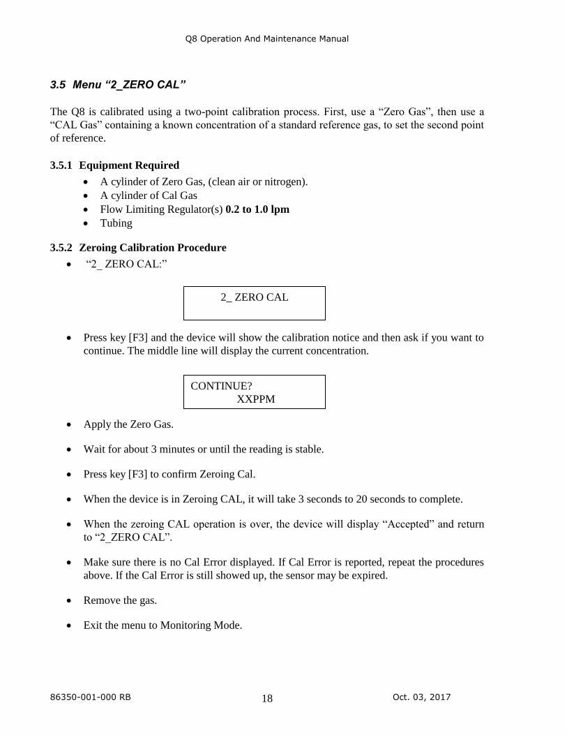
3.5.2 Zeroing Calibration Procedure
• “2_ ZERO CAL:”
• Press key [F3] and the device will show the calibration notice and then ask if you want to
continue. The middle line will display the current concentration.
• Apply the Zero Gas.
• Wait for about 3 minutes or until the reading is stable.
• Press key [F3] to confirm Zeroing Cal.
• When the device is in Zeroing CAL, it will take 3 seconds to 20 seconds to complete.
• When the zeroing CAL operation is over, the device will display “Accepted” and return
to “2_ZERO CAL”.
• Make sure there is no Cal Error displayed. If Cal Error is reported, repeat the procedures
above. If the Cal Error is still showed up, the sensor may be expired.
• Remove the gas.
• Exit the menu to Monitoring Mode.
2_ ZERO CAL
CONTINUE?
XXPPM
Q8 Operation And Maintenance Manual
86350-001-000 RB Oct. 03, 2017 19
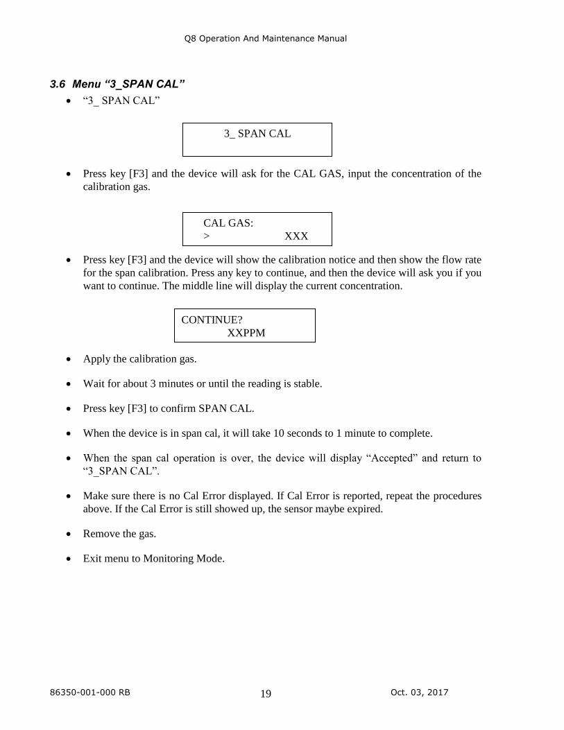
3.6 Menu “3_SPAN CAL”
• “3_ SPAN CAL”
• Press key [F3] and the device will ask for the CAL GAS, input the concentration of the
calibration gas.
• Press key [F3] and the device will show the calibration notice and then show the flow rate
for the span calibration. Press any key to continue, and then the device will ask you if you
want to continue. The middle line will display the current concentration.
• Apply the calibration gas.
• Wait for about 3 minutes or until the reading is stable.
• Press key [F3] to confirm SPAN CAL.
• When the device is in span cal, it will take 10 seconds to 1 minute to complete.
• When the span cal operation is over, the device will display “Accepted” and return to
“3_SPAN CAL”.
• Make sure there is no Cal Error displayed. If Cal Error is reported, repeat the procedures
above. If the Cal Error is still showed up, the sensor maybe expired.
• Remove the gas.
• Exit menu to Monitoring Mode.
3_ SPAN CAL
CAL GAS:
> XXX
CONTINUE?
XXPPM
Q8 Operation And Maintenance Manual
86350-001-000 RB Oct. 03, 2017 20
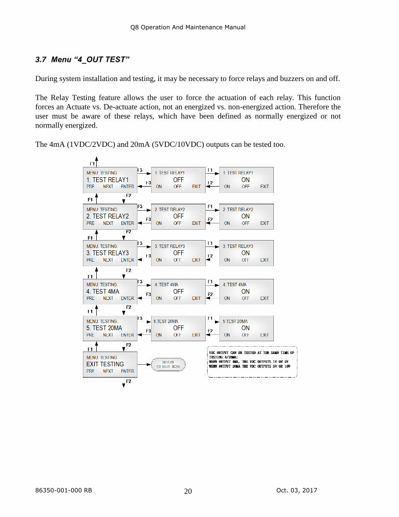
3.7 Menu “4_OUT TEST”
During system installation and testing, it may be necessary to force relays and buzzers on and off.
The Relay Testing feature allows the user to force the actuation of each relay. This function
forces an Actuate vs. De-actuate action, not an energized vs. non-energized action. Therefore the
user must be aware of these relays, which have been defined as normally energized or not
normally energized.
The 4mA (1VDC/2VDC) and 20mA (5VDC/10VDC) outputs can be tested too.
Q8 Operation And Maintenance Manual
86350-001-000 RB Oct. 03, 2017 21
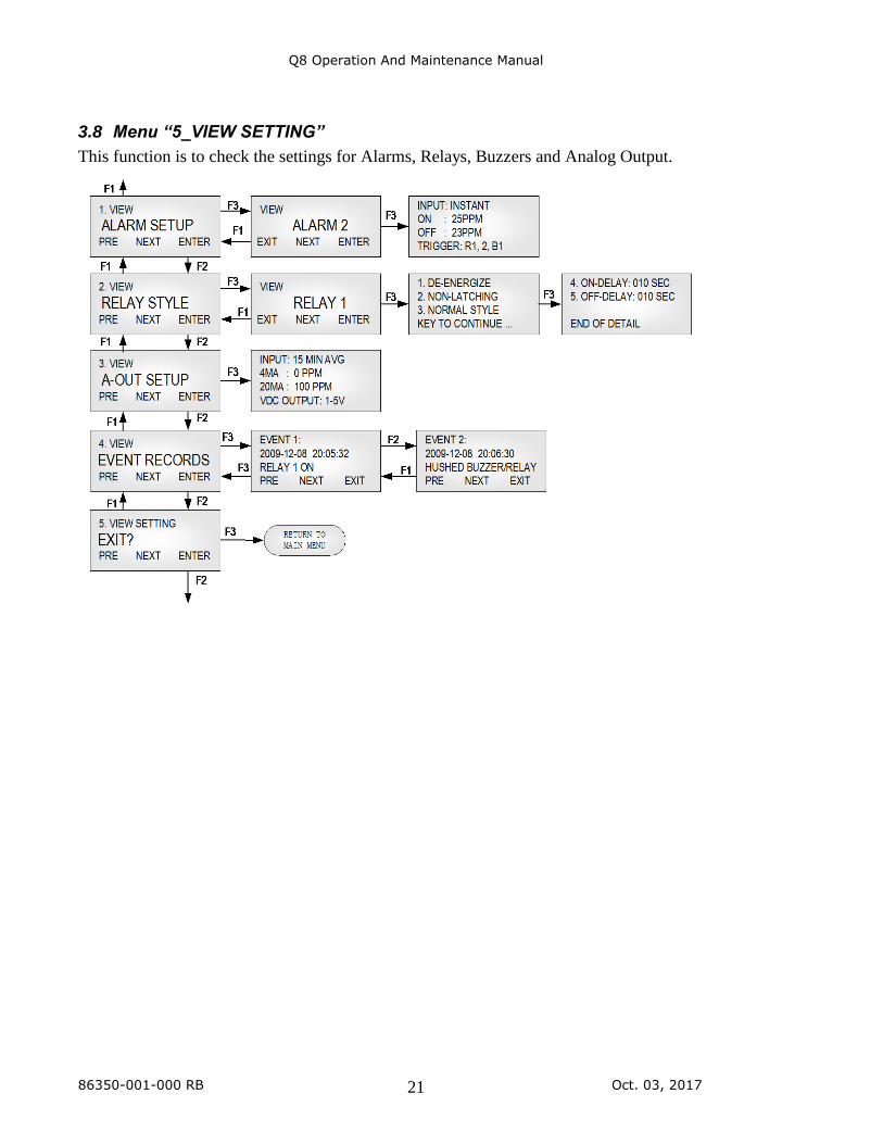
3.8 Menu “5_VIEW SETTING”
This function is to check the settings for Alarms, Relays, Buzzers and Analog Output.
Q8 Operation And Maintenance Manual
86350-001-000 RB Oct. 03, 2017 22
3.9 Menu “6_ALARM SETUP”
The Q8 supports alarm 1 to alarm 8.
Alarm is a programmable condition that can receive a selectable input and trigger relays and
buzzers.
Disabled or
Enabled:
Each alarm may be individually set to be enabled or disabled. If the alarm
is disabled, the alarm will not be used to calculate or trigger anything.
Default: Alarm 1 to Alarm 4 is enabled. Alarm 5 to Alarm 8 is
disabled.
Input: One of five inputs is selected to calculate the alarm condition status to
trigger the selected outputs:
• INSTANT: instantaneous gas reading.
• 15 MIN AVG (STEL): Short Term Exposure Limit, average
reading over 15 minutes.
• 8 HOURS AVG (TWA): 8-hour Time Weighted Average, average
reading over 8 hours.
• DAILY PEAK: daily peak reading.
• FAULT: If the unit reports any faults, no matter the gas
concentration, it will trigger the selected outputs.
Alarm On
and
Alarm Off
Reading:
If Alarm On is greater than or equal to Alarm Off:
Alarm On: Sets the concentration at or above which the relay will actuate.
Alarm Off: Sets the concentration at or below which the relay will de-
actuate.
If Action On is less than Action Off:
Action On: Sets the concentration below that the relay will actuate.
Action Off: Sets the concentration above that the relay will de-actuate.
Trigger: Trigger Outputs: Relay 1, Relay 2, Relay 3, Buzzer 1, Buzzer 2, Buzzer 3
Q8 Operation And Maintenance Manual
86350-001-000 RB Oct. 03, 2017 23
3.10 Menu “7_RELAY STYLE”
Enabled:
Each relay may be individually set to be enabled or disabled. If it’s
disabled, the relay will always de-actuate no matter what the current gas
concentration.
Default is Enabled.
Normally
De-
energized:
Each relay may be individually set to be normally energized or normally
de-energized.
Default is normally de-energized.
Latching: Each relay may be set to latch in actuate status until acknowledged by a
front-panel action.
Default is Non-Latching.
ON Delay: “Delay on Actuation” or “Delay on Make”. For each relay a separate time
delay may be set from 0 to 990 seconds before an alarm condition will
cause the relay to actuate.
Default is 5 seconds.
OFF Delay: “Delay on De-Actuation” or “Delay on Break”. For each relay a separate
time delay may be set from 0 to 990 seconds before a return to a non-
alarming signal condition will cause the relay to de-actuate.
Default is 5 seconds.
Style: Normal Relay Style: Work as normal relay.
Buzzer Style Relay: When the relay is used to control a buzzer or horn.
Working as a buzzer style will make the relay have the same function as
the buzzer. It will be switched off when performing the Hush
Buzzer/Relay function in the Tool Menu.
Default is OFF.
Q8 Operation And Maintenance Manual
86350-001-000 RB Oct. 03, 2017 24
3.11 Menu “8_BUZZER STYLE”
Not function in the Q8.
3.12 Menu “9_A-OUT SETUP”
The Q8 will compare the concentration at 4mA and the concentration at 20mA. You may assign
a larger concentration for 4mA than for 20 mA; the Q8 will still stretch a straight line signal
between the two points and then convert the selected gas reading to analog output.
Input: One of four inputs is selected to calculate the analog outputs:
• INSTANT: instantaneous gas reading.
• 15 MIN AVG (STEL): Short Term Exposure Limit, average
reading over 15 minutes.
• 8 HOURS AVG (TWA): 8-hour Time Weighted Averages,
average reading over 8 hours.
• DAILY PEAK: daily peak reading.
Out 4mA at
Conc:
Input the gas concentration at which 4mA is output.
Out 20mA at
Conc:
Input the gas concentration at which 20mA is output.
VDC Output: VDC Output can be selected from:
• 1-5VDC or 2-10VDC
Note: The analog output cannot be disabled.
Note: When the sensor has a fault, the output will be 2.5mA to indicate fault status.
3.13 Menu “A_ALL DISABLE”
This function is for calibration, system testing etc. When All Disable is ON, the status of the
relay, buzzer and analog output, etc., will freeze in their current state.
Default is OFF.
Q8 Operation And Maintenance Manual
86350-001-000 RB Oct. 03, 2017 25
3.14 Menu “B_SIMULATION”
Simulation mode is used to assist in testing the installation before commissioning. When
simulation is enabled, the unit will not detect gas concentrations; it will display the simulated
value and use it to calculate the status of relays and buzzers, as well as the 4-20mA analog
output. This feature is available for evaluating the user settings and testing the installation (e.g.:
the activation of the valve, fan speed, relay set points, etc. can be verified.)
Any concentration between 0ppm and 9999ppm can be simulated.
3.15 Menu “C_SITE SERVICE” and “D_FACTROY SET”
Factory service staff access only. The customer has no need to operate it.
4. MODBUS Protocol Supported By Q8
For ModBus protocol, please contact ACI.
Q8 Operation And Maintenance Manual
86350-001-000 RB Oct. 03, 2017 26
5. Maintenance
5.1 DVM connection for 4-20mA measurement
• Interrupt the 4-20mA signal going from the Q8 to the controller (causing a fault):
o Switch the DVM to measure DC current, on the main board plug the negative
probe into GND and plug the positive probe into mA-.
• Monitor the 4-20mA signal going from the Q8 to the controller (not causing a fault):
o Switch the DVM to measure DC current, on the main board plug the negative
probe into mA- and plug the positive probe into mA+.
5.2 4mA and 20mA Output Calibration
These values are established during the factory 4-20mA output calibrations and should not
require recalibration in the field. Do not attempt to modify these settings in the field.
Changing these values will change the analog output signal scale.
• Entry [Menu]-->[System Setting]
• Choose [Out 4mA CAL]:
1. Press key [F3] to output the 4mA signal.
2. Connect the DVM to the unit as described above.
3. Press key [F1] or key [F2] to adjust the current to 4.00mA to 4.05mA.
4. Press key [F3], then the settings will be accepted and saved.
• Choose [Out 20mA CAL]:
1. Press key [F3] to output the 20mA signal.
2. Connect the DVM to the unit as described above.
3. Press key [F1] or key [F2] to adjust the current to 20.00 to 20.05mA.
4. Press key [F3], then the settings will be accepted and saved
Q8 Operation And Maintenance Manual
86350-001-000 RB Oct. 03, 2017 27
5.3 Smart Sensor Assembly Replacement
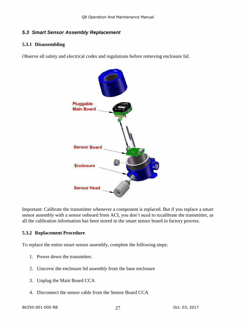
5.3.1 Disassembling
Observe all safety and electrical codes and regulations before removing enclosure lid.
Important: Calibrate the transmitter whenever a component is replaced. But if you replace a smart
sensor assembly with a sensor onboard from ACI, you don’t need to recalibrate the transmitter, as
all the calibration information has been stored in the smart sensor board in factory process.
5.3.2 Replacement Procedure
To replace the entire smart sensor assembly, complete the following steps:
1. Power down the transmitter.
2. Unscrew the enclosure lid assembly from the base enclosure
3. Unplug the Main Board CCA
4. Disconnect the sensor cable from the Sensor Board CCA

Q8 Operation And Maintenance Manual
86350-001-000 RB Oct. 03, 2017 28
5. Unscrew the two rods to release the smart sensor board from the base enclosure
6. Unscrew the sensor head from the base enclosure if the sensor head needs to replace too
7. If to only replace electrochemical sensor cell or NDIR sensor cell from the sensor head,
unscrew the lid of the sensor head to unplug the sensor cell from the socket
8. Plug the new sensor or replace new sensor head
9. Screw new smart sensor assembly and secure with two rods. Ensure that the connectors
are correctly matched each other. Incorrect connection may damage the sensor assembly
and/or the Main Board.
10. Plug the Main Board to the two rods
11. Screw back the lid enclosure
Q8 Operation And Maintenance Manual
86350-001-000 RB Oct. 03, 2017 29
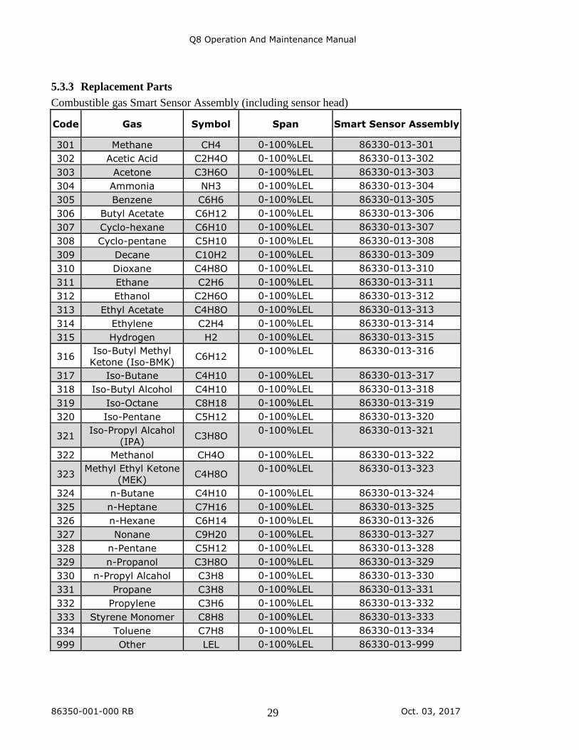
5.3.3 Replacement Parts
Combustible gas Smart Sensor Assembly (including sensor head)
Code Gas Symbol Span Smart Sensor Assembly
301 Methane CH4 0-100%LEL 86330-013-301
302 Acetic Acid C2H4O 0-100%LEL 86330-013-302
303 Acetone C3H6O 0-100%LEL 86330-013-303
304 Ammonia NH3 0-100%LEL 86330-013-304
305 Benzene C6H6 0-100%LEL 86330-013-305
306 Butyl Acetate C6H12 0-100%LEL 86330-013-306
307 Cyclo-hexane C6H10 0-100%LEL 86330-013-307
308 Cyclo-pentane C5H10 0-100%LEL 86330-013-308
309 Decane C10H2 0-100%LEL 86330-013-309
310 Dioxane C4H8O 0-100%LEL 86330-013-310
311 Ethane C2H6 0-100%LEL 86330-013-311
312 Ethanol C2H6O 0-100%LEL 86330-013-312
313 Ethyl Acetate C4H8O 0-100%LEL 86330-013-313
314 Ethylene C2H4 0-100%LEL 86330-013-314
315 Hydrogen H2 0-100%LEL 86330-013-315
316 Iso-Butyl Methyl
Ketone (Iso-BMK) C6H12
0-100%LEL 86330-013-316
317 Iso-Butane C4H10 0-100%LEL 86330-013-317
318 Iso-Butyl Alcohol C4H10 0-100%LEL 86330-013-318
319 Iso-Octane C8H18 0-100%LEL 86330-013-319
320 Iso-Pentane C5H12 0-100%LEL 86330-013-320
321 Iso-Propyl Alcahol
(IPA) C3H8O
0-100%LEL 86330-013-321
322 Methanol CH4O 0-100%LEL 86330-013-322
323 Methyl Ethyl Ketone
(MEK) C4H8O
0-100%LEL 86330-013-323
324 n-Butane C4H10 0-100%LEL 86330-013-324
325 n-Heptane C7H16 0-100%LEL 86330-013-325
326 n-Hexane C6H14 0-100%LEL 86330-013-326
327 Nonane C9H20 0-100%LEL 86330-013-327
328 n-Pentane C5H12 0-100%LEL 86330-013-328
329 n-Propanol C3H8O 0-100%LEL 86330-013-329
330 n-Propyl Alcahol C3H8 0-100%LEL 86330-013-330
331 Propane C3H8 0-100%LEL 86330-013-331
332 Propylene C3H6 0-100%LEL 86330-013-332
333 Styrene Monomer C8H8 0-100%LEL 86330-013-333
334 Toluene C7H8 0-100%LEL 86330-013-334
999 Other LEL 0-100%LEL 86330-013-999
Q8 Operation And Maintenance Manual
86350-001-000 RB Oct. 03, 2017 30
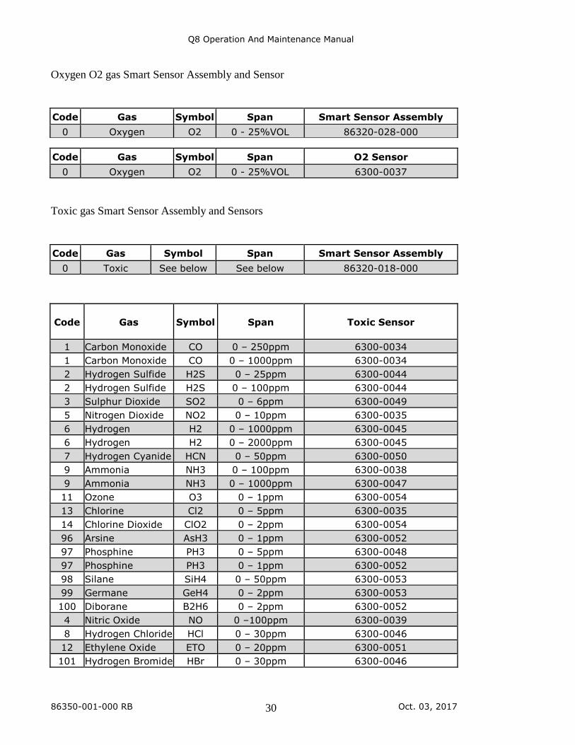
Oxygen O2 gas Smart Sensor Assembly and Sensor
Toxic gas Smart Sensor Assembly and Sensors
Code Gas Symbol
Span
Toxic Sensor
1 Carbon Monoxide CO 0 – 250ppm 6300-0034
1 Carbon Monoxide CO 0 – 1000ppm 6300-0034
2 Hydrogen Sulfide H2S 0 – 25ppm 6300-0044
2 Hydrogen Sulfide H2S 0 – 100ppm 6300-0044
3 Sulphur Dioxide SO2 0 – 6ppm 6300-0049
5 Nitrogen Dioxide NO2 0 – 10ppm 6300-0035
6 Hydrogen H2 0 – 1000ppm 6300-0045
6 Hydrogen H2 0 – 2000ppm 6300-0045
7 Hydrogen Cyanide HCN 0 – 50ppm 6300-0050
9 Ammonia NH3 0 – 100ppm 6300-0038
9 Ammonia NH3 0 – 1000ppm 6300-0047
11 Ozone O3 0 – 1ppm 6300-0054
13 Chlorine Cl2 0 – 5ppm 6300-0035
14 Chlorine Dioxide ClO2 0 – 2ppm 6300-0054
96 Arsine AsH3 0 – 1ppm 6300-0052
97 Phosphine PH3 0 – 5ppm 6300-0048
97 Phosphine PH3 0 – 1ppm 6300-0052
98 Silane SiH4 0 – 50ppm 6300-0053
99 Germane GeH4 0 – 2ppm 6300-0053
100 Diborane B2H6 0 – 2ppm 6300-0052
4 Nitric Oxide NO 0 –100ppm 6300-0039
8 Hydrogen Chloride HCl 0 – 30ppm 6300-0046
12 Ethylene Oxide ETO 0 – 20ppm 6300-0051
101 Hydrogen Bromide HBr 0 – 30ppm 6300-0046
Code Gas Symbol Span Smart Sensor Assembly
0 Oxygen O2 0 - 25%VOL 86320-028-000
Code Gas Symbol Span O2 Sensor
0 Oxygen O2 0 - 25%VOL 6300-0037
Code Gas Symbol Span Smart Sensor Assembly
0 Toxic See below See below 86320-018-000
Q8 Operation And Maintenance Manual
86350-001-000 RB Oct. 03, 2017 31
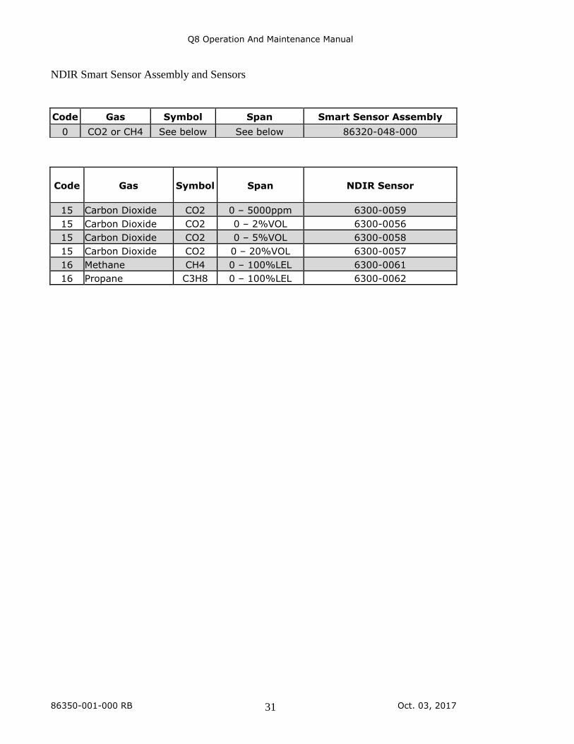
NDIR Smart Sensor Assembly and Sensors
Code Gas Symbol
Span
NDIR Sensor
15 Carbon Dioxide CO2 0 – 5000ppm 6300-0059
15 Carbon Dioxide CO2 0 – 2%VOL 6300-0056
15 Carbon Dioxide CO2 0 – 5%VOL 6300-0058
15 Carbon Dioxide CO2 0 – 20%VOL 6300-0057
16 Methane CH4 0 – 100%LEL 6300-0061
16 Propane C3H8 0 – 100%LEL 6300-0062
Code Gas Symbol Span Smart Sensor Assembly
0 CO2 or CH4 See below See below 86320-048-000
Q8 Operation And Maintenance Manual
86350-001-000 RB Oct. 03, 2017 32
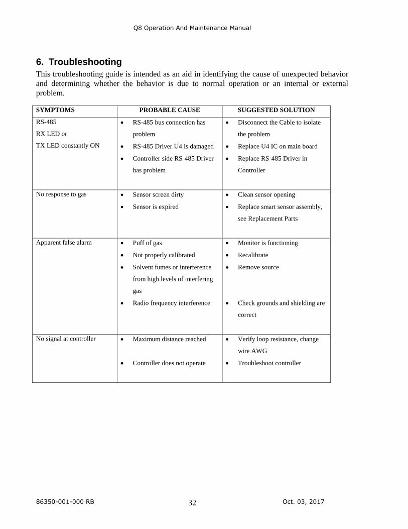
6. Troubleshooting
This troubleshooting guide is intended as an aid in identifying the cause of unexpected behavior
and determining whether the behavior is due to normal operation or an internal or external
problem.
SYMPTOMS PROBABLE CAUSE SUGGESTED SOLUTION
RS-485
RX LED or
TX LED constantly ON
• RS-485 bus connection has
problem
• RS-485 Driver U4 is damaged
• Controller side RS-485 Driver
has problem
• Disconnect the Cable to isolate
the problem
• Replace U4 IC on main board
• Replace RS-485 Driver in
Controller
No response to gas • Sensor screen dirty
• Sensor is expired
• Clean sensor opening
• Replace smart sensor assembly,
see Replacement Parts
Apparent false alarm • Puff of gas
• Not properly calibrated
• Solvent fumes or interference
from high levels of interfering
gas
• Radio frequency interference
• Monitor is functioning
• Recalibrate
• Remove source
• Check grounds and shielding are
correct
No signal at controller • Maximum distance reached
• Controller does not operate
• Verify loop resistance, change
wire AWG
• Troubleshoot controller
Q8 Operation And Maintenance Manual
86350-001-000 RB Oct. 03, 2017 33
WARRANTY STATEMENT
All ACI equipment is warranted against defects in material and workmanship for a period of two years
from date of shipment with the following exceptions:
Electrochemical Sensors (Toxic) Six Months
Catalytic Sensors (Combustible) One Year
Full warranty information can be found on ACI’s website:
http://www.workaci.com/sites/default/files/warranty.pdf
LIMITED LIABILITY
All ACI systems shall be installed by a qualified technician/electrician and maintained in strict
accordance with data provided for individual systems in the form of installation/maintenance manuals.
ACI assumes no responsibility for improper installation, maintenance, etc., and stresses the importance of
reading all manuals. ACI shall not be responsible for any liability arising from auxiliary interfaced
equipment nor any damage resulting from the installation or operation of this equipment.
ACI’s total liability is contained as above with no other liability expressed or implied as the purchaser is
entirely responsible for installation and maintenance of systems.
This warranty is in lieu of all other warranties, expressed or implied, and no representative or person is
authorized to represent or assume for ACI any liability in connection with the sales of our products other
than that set forth herein.
NOTE: Due to on-going product development, ACI reserves the right to change specifications
without notice and will assume no responsibility for any costs as a result of
modifications.
For further information or assistance, contact:
AUTOMATION COMPONENTS, INC.
2305 Pleasant View Road
Middleton, Wisconsin
Tel: (888) 967-5224
Fax: (608) 831-7407
Web: workaci.com