MODEL: PG 1150 AM - PowerGen · MODEL: PG 1150 AM GENERATING SET PROFORMANCE 50Hz 60Hz ... (ASTM...
24
MODEL: PG 1150 AM GENERATING SET PROFORMANCE 50Hz 60Hz VOLTAGE V400 PHASES Three PRIME RATED POWER 1150kVA STANDBY RATED POWER 1250kVA POWER FACTOR 0.80 PF FUEL USAGE @ 75% 165.0 L/hr Powered by:
Transcript of MODEL: PG 1150 AM - PowerGen · MODEL: PG 1150 AM GENERATING SET PROFORMANCE 50Hz 60Hz ... (ASTM...
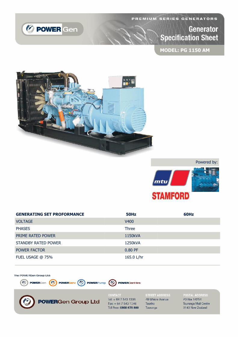
MODEL: PG 1150 AM
GENERATING SET PROFORMANCE 50Hz 60Hz
VOLTAGE V400
PHASES Three
PRIME RATED POWER 1150kVA
STANDBY RATED POWER 1250kVA
POWER FACTOR 0.80 PF
FUEL USAGE @ 75% 165.0 L/hr
Powered by:

ENGINE MTU 18V 2000 G65
PERFORMANCE 50Hz 60Hz
BASELOAD RATED POWER TBA
PRIME RATED POWER 1000KWm
STANDBY RATED POWER 1100KWm
FUEL CONSUMPTION 238 L/hr @ 100%165 L/hr @ 75%120 L/hr @ 50%
TYPE Diesel 4 stroke
ASPIRATION
INJECTION TYPE Direct injection
ENGINE GOVERNOR Electronic governor
CYLINDERS AND ARRANGEMENT 18 Vee
BORE AND STROKE 130mm x 150mm
COMPRESSION RATIO 16.0 : 1
ELECTRICAL SYSTEM VOLTAGE 24 volt
BATTERY TYPE Lead acid, 24V
DERATING FOR TEMPERATURE 40deg C
DERATING FOR ALTITUDE 1000m
DERATING FOR HUMIDITY 90%
Turbocharged
ENGINE

ALTERNATOR STAMFORD
PERFORMANCE 50Hz 60Hz
MODEL HCI634K
BASELOAD RATED POWER 40 deg C 1018kVA
PRIME RATED POWER 40 deg C 1130kVA
STANDBY RATED POWER 40 deg C 1190kVA
STANDBY RATED POWER 27 deg C 1230kVA
EFFICIENCY 95%
STANDARD WING CONNECTIONS Star Delta
EXCITER
POLES 4 poles
PHASES Three phases
WIRES 6 leads
VOLTAGE REGULATION +/- 0.5%
INSULATION CLASS Class H
ENCLOSURE IP23
MAXIMUM OVERSPEED 150%
STANDARD AVR MODEL MX321
OPTIONAL AVR MODEL TBA
DERATING FOR TEMPERATURE 40 deg C
DERATING FOR ALTITUDE 1000mm
Separately excited by P.M.G
ALTERNATOR

GENERATOR EQUIPMENT
DIMENSIONS AND CAPACITY
STANDARD MODELS
INTEGATED FUEL TANK CA-PACITY
WEIGHT
STANDARD OPTIONAL KG LENGTH WIDTH HEIGHT
OPEN SKID TYPE - TBA 9300kg 4700mm 1900mm 2430mm
DIMENSIONS
DIMENSIONS

CONTROLLER
3 pole 1600A ABB circuit breaker with 24V shunt trip, Electronic control unit ComAp InteliGen-NT, Control panel box
key, Emergency Stop button, Water jacket heater , Battery charger,
Alternator Anti-condensation heater.
Low oil pressure, Low fuel level Low voltage, High Coolant Temperature, Over/Under battery voltage, Belt breakage,ROCOF, Reverse Power3 phase integrated generator protections (U + f), IDMTovercurrent + Shortcurrent protection, Overload protection, Reverse power protection, Earth faultprotection, 3 phase integrated mains protections (U + f), Vector shift protection, All binary/analogue inputs freeconfigurable for various protection types: HistRecOnly Alarm Only /Warning / Off load /Slow stop / Breaker Open&Cooldown / Shutdown / Mains protect / Sensor fail. Additional 160programmable protections configurable for any measured value to create customer-specificProtections.
AUTOMATIC MODELS – PROTECTORS
AUTOMATIC MODELS – INSTRUMENTATION
Analogue meters for Voltmeter , Ammeter (3 phases) , Frequency meter , Hour-meter , Battery voltage meter,Analogue gauges for Fuel level .Water Temp, oil Pressure, Battery charging current, Battery voltage.
AUTOMATIC MODELS—EQUIPMENT

Subj
ect
to a
ltera
tion
due
to t
echn
olog
ical
adv
ance
s.M
IM 0
5 19
5(5
2 3E
) 1/
08 ·
Prin
ted
in G
erm
any
· MIM
A 20
08-0
5 H
· Pr
inte
d on
chl
orin
e-fr
ee p
aper
.
PowerGen
Series 2000 G05Diesel Enginesfor Stationary Power Generation
The New Series 2000 G05!
Cleaner.
Low Emissions.
Advance Electronics.
More Powerful.
Europe / Middle East / Africa /Latin America
MTU Friedrichshafen GmbH88040 FriedrichshafenGermany
Phone +49 7541 90 7006Fax +49 7541 90 [email protected]
Asia / Australia /Pacific
MTU Asia Pte. Ltd.1, Benoi PlaceSingapore 629923Republic of SingaporePhone +65 6861 5922Fax +65 6861 [email protected]
USA / Canada /Mexico
MTU Detroit Diesel, Inc.13400 Outer Drive WestDetroit, Michigan 48239USAPhone +1 313 592 5708Fax +1 313 592 [email protected] www.mtudetroitdiesel.com
Tognum Group Companies

Supp
lyin
g yo
ur e
nerg
y ne
eds
Your
ben
efit
s:
Min
imal
ass
embl
y an
d en
gine
erin
g w
ork
>C
ompr
ehen
sive
ran
ge o
f ac
cess
orie
s(e
.g. a
ir f
ilter
s, e
xhau
st c
ompe
nsat
ors,
eng
ine
and
gene
rato
r m
ount
ings
, rad
iato
rs, e
tc.)
>O
ptim
ized
inte
rfac
e co
nfig
urat
ion
>Be
spok
e sy
stem
and
inst
alla
tion
plan
ning
Opt
imum
ope
rati
ng c
hara
cter
isti
cs>
Low
vib
rati
on p
rope
rtie
s>
Aut
omat
ic e
ngin
e pr
otec
tion
if am
bien
t co
nditi
ons
chan
ge(E
SCM
– E
ngin
e Si
te C
ondi
tion
Man
agem
ent
Syst
em)
>O
utst
andi
ng lo
ad r
espo
nse
char
acte
rist
ics
>H
igh
stab
ility
of
spee
d an
d fr
eque
ncy
Envi
ronm
enta
lly s
ound
>Le
ader
s in
nat
iona
l and
inte
rnat
iona
l em
issi
ons
stan
dard
sco
mpl
ianc
e>
Low
fue
l and
lubr
ican
t co
nsum
ptio
n>
Low
noi
se a
nd v
ibra
tion
out
put
>Fi
nish
ed in
eco
logi
cally
saf
e pa
ints
Hig
h sy
stem
ava
ilabi
lity
and
relia
bilit
y>
Long
ser
vice
life
>24
-hou
r su
ppor
t se
rvic
e>
Glo
bal c
usto
mer
ser
vice
net
wor
k w
ith ≥
1,1
00 s
ervi
cece
nter
s>
Elec
tron
ic e
ngin
e m
anag
emen
t sy
stem
with
sel
f-di
agno
sis
func
tion
and
rem
ote
diag
nosi
s ca
pabi
lity
Low
life
-cyc
le c
osts
>A
ttra
ctiv
e pr
ice
>Lo
w f
uel c
onsu
mpt
ion
>Lo
w o
il co
nsum
ptio
n>
Ease
of
mai
nten
ance
>Lo
ng T
BO>
REM
AN
par
ts
MTU
eng
ines
are
the
bas
is fo
r re
liabl
e an
d
econ
omic
al p
ower
gen
erat
ion
solu
tion
s.
The
enha
nced
-per
form
ance
Ser
ies
2000
G05
offe
rs im
pres
sive
ly lo
w f
uel c
onsu
mpt
ion,
low
emis
sion
s an
d lo
ng s
ervi
ce in
terv
als.
The
exte
nsiv
e ch
oice
of
inte
grat
ed a
cces
sori
es
also
hel
ps y
ou t
o re
duce
the
eng
inee
ring
com
-
plex
ity.
The
elec
tron
ic e
ngin
e m
anag
emen
t sy
stem
is
capa
ble
of p
erfo
rmin
g a
com
preh
ensi
ve r
ange
of c
ontr
ol a
nd m
onito
ring
fun
ctio
ns, n
ot o
nly
for
the
engi
ne, b
ut a
lso
for
the
inst
alla
tion
.
This
will
sub
stan
tially
red
uce
plan
ning
com
plex
ity a
nd w
ill m
ake
syst
em c
ontr
ol
sim
pler
and
mor
e co
st e
ffec
tive.
With
the
com
preh
ensi
ve c
hoic
e of
pow
er
outp
uts,
the
Ser
ies
2000
G05
engi
nes
offe
r
the
opti
mum
sol
utio
n fo
r al
l app
licat
ions
.
Seri
es 2
000
G05
tech
nolo
gy:
Supe
rior
in e
very
det
ail.
AD
EC (
Adv
ance
d D
iese
l En
gine
Con
trol
ler)
eng
ine
man
agem
ent
Elec
tron
ic e
ngin
e m
anag
emen
t co
n-tr
olle
r w
ith e
nhan
ced
proc
esso
r pe
r-fo
rman
ce fo
r ec
onom
ical
fue
l con
-su
mpt
ion
and
com
plia
nce
with
cur
rent
exha
ust
emis
sion
s re
quir
emen
ts.
Com
patib
le w
ith a
var
iety
of
fuel
inje
ctio
n an
d in
ject
or t
ypes
. To
ugh,
vib
ratio
n-re
sist
ant
desi
gn w
ithw
ide
oper
atin
g te
mpe
ratu
re r
ange
.
Ben
efit
s:
>O
ptim
um o
pera
ting
cha
ract
eris
tics
>O
utst
andi
ng lo
ad r
espo
nse
char
ac-
teri
stic
s
>M
aint
enan
ce-f
ree
desi
gn
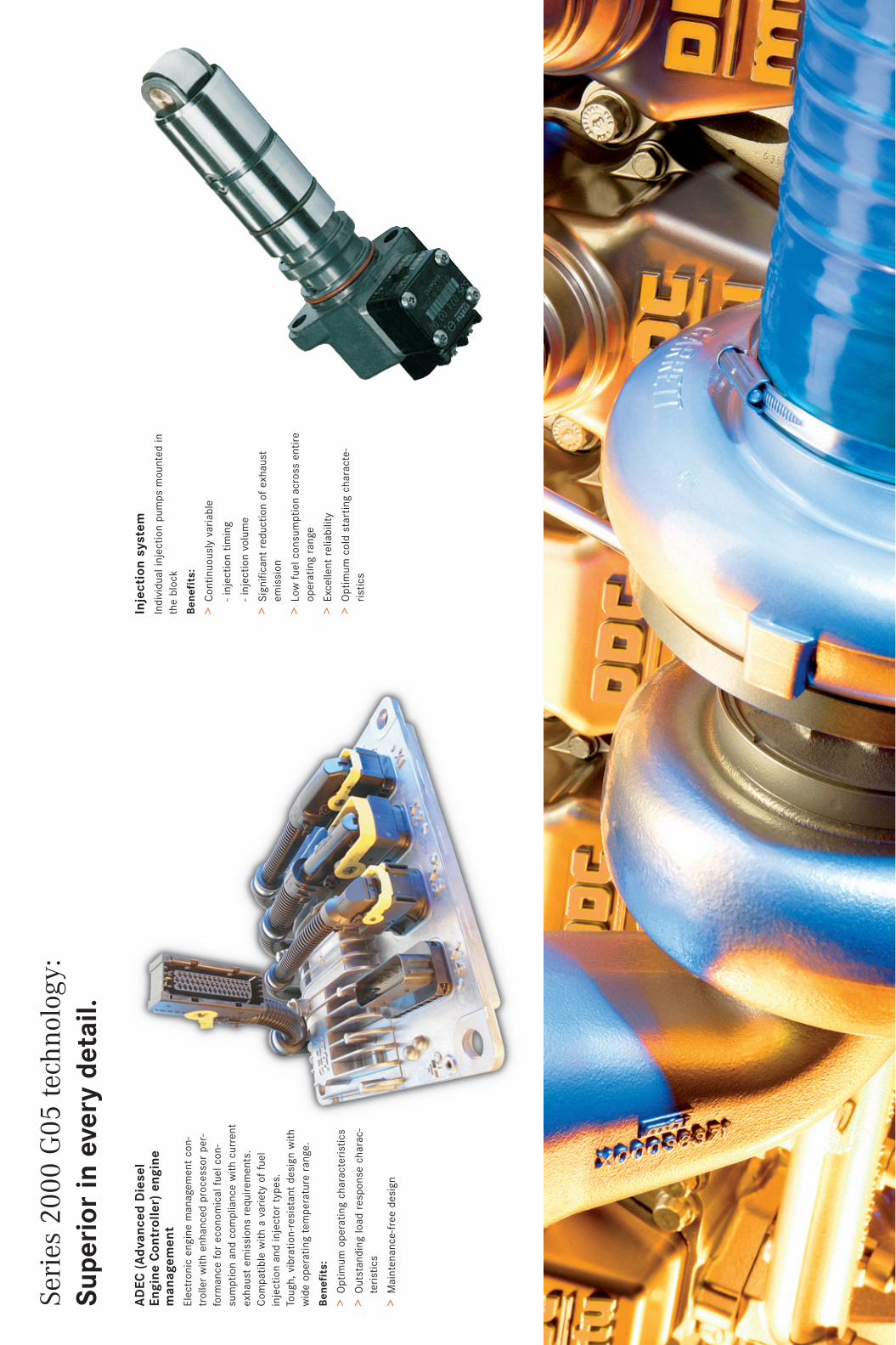
Inje
ctio
n sy
stem
Indi
vidu
al in
ject
ion
pum
ps m
ount
ed in
the
bloc
k
Ben
efit
s:
>C
ontin
uous
ly v
aria
ble
- in
ject
ion
tim
ing
- in
ject
ion
volu
me
>Si
gnifi
cant
red
ucti
on o
f ex
haus
tem
issi
on
>Lo
w f
uel c
onsu
mpt
ion
acro
ss e
ntir
eop
erat
ing
rang
e
>Ex
celle
nt r
elia
bilit
y
>O
ptim
um c
old
star
ting
cha
ract
e-ri
stic
s

Series 2000 G05 technology: Superior in every detail.
ADEC (Advanced Diesel Engine Controller) enginemanagementElectronic engine management con-troller with enhanced processor per-formance for economical fuel con-sumption and compliance with currentexhaust emissions requirements.Compatible with a variety of fuelinjection and injector types. Tough, vibration-resistant design withwide operating temperature range.
Benefits:
> Optimum operating characteristics
> Outstanding load response charac-teristics
> Maintenance-free design
ADEC electronic enginemanagement module> Engine monitoring and management
> Communication with auxiliarysystems via CAN bus (and approp-riate interface module)
> Self-monitoring and diagnosis
> Extensive input/output channels
> Programming and configurationusing interactive device via MCS-5CAN bus interface
SAM Service ApplicationModule> Display of warnings, alerts,
operating information and faultcodes
> Redundant data backup
> Web server access and remotediagnosis
> Life data recording
> External controller connection viaCAN bus/SAE J 1939 using a buscard
LCD display (color)> Display of operating data and alerts
> 5 function keys for operatorguidance
> Integrated backlighting
Analog instruments> Engine speed
> Oil pressure
> Coolant temperature
> Oil temperature
�
�
��
���SAM+ Service Application ModuleExtra features in addition to basic SAMspecifications:
> Fuel level display and monitoring of immediate-supply tank and mainreservoir tank
> Fan/vent control
> Generator exciter boost control
> Monitoring of generator windingtemperature
> Preheat control and circulation pumpcontrol
> Speed boost control
> Load uptake ready signal
> Fuel prefilter monitoring
> Selection of second controller data record
��

Seri
es 2
000
G05
tech
nolo
gy:
Supe
rior
in e
very
det
ail.
AD
EC (
Adv
ance
d D
iese
l En
gine
Con
trol
ler)
eng
ine
man
agem
ent
Elec
tron
ic e
ngin
e m
anag
emen
t co
n-tr
olle
r w
ith e
nhan
ced
proc
esso
r pe
r-fo
rman
ce fo
r ec
onom
ical
fue
l con
-su
mpt
ion
and
com
plia
nce
with
cur
rent
exha
ust
emis
sion
s re
quir
emen
ts.
Com
patib
le w
ith a
var
iety
of
fuel
inje
ctio
n an
d in
ject
or t
ypes
. To
ugh,
vib
ratio
n-re
sist
ant
desi
gn w
ithw
ide
oper
atin
g te
mpe
ratu
re r
ange
.
Ben
efit
s:
>O
ptim
um o
pera
ting
cha
ract
eris
tics
>O
utst
andi
ng lo
ad r
espo
nse
char
ac-
teri
stic
s
>M
aint
enan
ce-f
ree
desi
gn
AD
EC e
lect
roni
c en
gine
man
agem
ent
mod
ule
>En
gine
mon
itori
ng a
nd m
anag
emen
t
>C
omm
unic
atio
n w
ith a
uxili
ary
syst
ems
via
CA
N b
us (
and
appr
op-
riat
e in
terf
ace
mod
ule)
>Se
lf-m
onito
ring
and
dia
gnos
is
>Ex
tens
ive
inpu
t/ou
tput
cha
nnel
s
>Pr
ogra
mm
ing
and
conf
igur
atio
nus
ing
inte
ract
ive
devi
ce v
ia M
CS-
5C
AN
bus
inte
rfac
e
SAM
Ser
vice
App
licat
ion
Mod
ule
>D
ispl
ay o
f w
arni
ngs,
ale
rts,
oper
atin
g in
form
atio
n an
d fa
ult
code
s
>Re
dund
ant
data
bac
kup
>W
eb s
erve
r ac
cess
and
rem
ote
diag
nosi
s
>Li
fe d
ata
reco
rdin
g
>Ex
tern
al c
ontr
olle
r co
nnec
tion
via
CA
N b
us/
SAE
J 19
39 u
sing
a b
usca
rd
LCD
dis
play
(co
lor)
>D
ispl
ay o
f op
erat
ing
data
and
ale
rts
>5
func
tion
key
s fo
r op
erat
orgu
idan
ce
>In
tegr
ated
bac
klig
htin
g
Ana
log
inst
rum
ents
>En
gine
spe
ed
>O
il pr
essu
re
>C
oola
nt t
empe
ratu
re
>O
il te
mpe
ratu
re
�
�
��
��
�SA
M+
Serv
ice
App
licat
ion
Mod
ule
Extr
a fe
atur
es in
add
itio
n to
bas
ic S
AM
spec
ifica
tion
s:
>Fu
el le
vel d
ispl
ay a
nd m
onito
ring
of
imm
edia
te-s
uppl
y ta
nk a
nd m
ain
rese
rvoi
r ta
nk
>Fa
n/ve
nt c
ontr
ol
>G
ener
ator
exc
iter
boos
t co
ntro
l
>M
onito
ring
of
gene
rato
r w
indi
ngte
mpe
ratu
re
>Pr
ehea
t co
ntro
l and
cir
cula
tion
pum
pco
ntro
l
>Sp
eed
boos
t co
ntro
l
>Lo
ad u
ptak
e re
ady
sign
al
>Fu
el p
refil
ter
mon
itori
ng
>Se
lect
ion
of s
econ
d co
ntro
ller
data
rec
ord
��

Elec
tron
ic m
anag
emen
t, m
onito
ring
and
con
trol
sys
tem
with
spe
ed/
cylin
der
char
ge m
odul
atio
n (a
ltern
ativ
ely)
and
inte
grat
ed s
afet
y an
dse
lf-di
agno
sis
func
tions
. Aut
omat
ic e
ngin
e pr
otec
tion
func
tion
(ESC
M)
in r
espo
nse
to v
aria
tion
of
ambi
ent
para
met
ers.
Exp
anda
ble
by t
head
diti
on o
f co
lor
disp
lay
and
exte
nded
Ser
vice
App
licat
ion
Mod
ule
func
tion
s (S
AM
+). P
lug-
and-
run
conn
ecto
rs, a
utom
atic
sta
rter
and
load
prof
ile r
ecor
der.
Con
sum
ptio
n-op
tim
ized
or
emis
sion
s-op
tim
ized
eng
ine
tuni
ng. C
ompl
ete
with
eng
ine
sens
ors
and
wir
ing.
C
ombi
nabl
e w
ith a
ll w
idel
y us
ed g
ense
t co
ntro
l sys
tem
s.
The
elec
tron
ic m
anag
emen
t, c
onsi
stin
g of
AD
EC a
nd S
AM
, is
capa
ble
of p
erfo
rmin
g ex
tens
ive
cont
rol a
nd m
onito
ring
fun
ctio
ns fo
r th
ein
stal
latio
n. A
s a
resu
lt, p
lann
ing
com
plex
ity is
sub
stan
tially
red
uced
and
syst
em c
ontr
ol is
sim
pler
and
che
aper
.
ADEC
SA
M
Con
trol
, mon
itori
ng,
man
agem
ent.
Tech
nica
l dat
a
Seri
es 2
000-
05 D
iese
l Eng
ines
wit
h A
ir t
o A
ir C
harg
e-ai
r C
oolin
gC
onfig
urat
ion
12V,
16V
, 18V
- 90
°Bo
re/
Stro
kem
m13
0/15
0C
ylin
der
capa
city
I/cy
l.1.
99Fu
el s
peci
ficat
ion
EN 5
90; G
rade
-No.
1-D
/2-
D, (
ASTM
D97
5-00
)
App
licat
ion
grou
pPr
ime
pow
erSt
andb
y po
wer
3B3D
Engi
ne m
odel
Rate
d po
wer
kW
(bhp
) - 1
500
rpm
(50
Hz)
Opt
imiz
atio
n⌧
or �
⌧12
V 20
00 G
2558
0 (7
78)
635
(853
)12
V 20
00 G
6569
5(9
32)
765
(102
6)16
V 20
00 G
25
810
(108
6)89
0 (1
194)
16V
2000
G65
890
(119
4)97
5 (1
308)
18V
2000
G65
1000
(134
1)11
00 (1
475)
Engi
ne m
odel
Rate
d po
wer
kW
(bhp
) - 1
800
rpm
(60
Hz)
Opt
imiz
atio
n�
�
12V
2000
G45
710
(952
)78
0 (1
046)
12V
2000
G85
810
(108
6)89
0(1
194)
16V
2000
G45
91
5 (1
227)
1010
(135
5)16
V 20
00 G
8510
10 (1
355)
1115
(149
5)18
V 20
00 G
8511
91 (1
597)
1310
(175
7)
Opt
imiz
atio
ns:
�Ex
haus
t em
issi
on T
A-L
uft
(for
stan
dby
pow
er)
�Ex
haus
t em
issi
on E
PA 4
0 C
FR 8
9, S
tage
2
⌧Fu
el c
onsu
mpt
ion
Refe
renc
e co
ndit
ions
Ambi
ent
air
tem
pera
ture
25 °
CC
harg
e ai
r co
olan
t te
mp.
45 °
C (T
B)Am
bien
t ai
r pr
essu
re10
00 m
bar
Hei
ght
abov
e se
a le
vel
100
mRa
ted
pow
er v
aila
ble
up t
oAm
bien
t ai
r te
mpe
ratu
re40
°C
Hei
ght
abov
e se
a le
vel
400
m
Engi
nes
avai
labl
e al
so w
ith
exte
rnal
cha
rge-
air
cool
ing
App
licat
ion
Def
init
ion
3B
Con
tinu
ous
oper
atio
n Lo
ad f
acto
r:<
75 %
wit
h va
riab
le l
oad
Ope
rati
ng h
ours
/ye
ar:
unre
stri
cted
Ove
rloa
d:10
% c
apab
ility
(IC
XN
)
3D
Stan
dby
oper
atio
n Lo
ad f
acto
r:<
85 %
wit
h va
riab
le l
oad
Ope
rati
ng h
ours
/ye
ar:
max
. 50
0 h
Ove
rloa
d:Fu
el s
top
(IC
FN)
Subj
ect
to a
ltera
tion
due
to t
echn
olog
ical
adv
ance
s.M
IM 0
5 19
5(5
2 3E
) 1/
08 ·
Prin
ted
in G
erm
any
· MIM
A 20
08-0
5 H
· Pr
inte
d on
chl
orin
e-fr
ee p
aper
.
PowerGen
Series 2000 G05Diesel Enginesfor Stationary Power Generation
The New Series 2000 G05!
Cleaner.
Low Emissions.
Advance Electronics.
More Powerful.
Europe / Middle East / Africa /Latin America
MTU Friedrichshafen GmbH88040 FriedrichshafenGermany
Phone +49 7541 90 7006Fax +49 7541 90 [email protected]
Asia / Australia /Pacific
MTU Asia Pte. Ltd.1, Benoi PlaceSingapore 629923Republic of SingaporePhone +65 6861 5922Fax +65 6861 [email protected]
USA / Canada /Mexico
MTU Detroit Diesel, Inc.13400 Outer Drive WestDetroit, Michigan 48239USAPhone +1 313 592 5708Fax +1 313 592 [email protected] www.mtudetroitdiesel.com
Tognum Group Companies

HCI634K - Technical Data Sheet
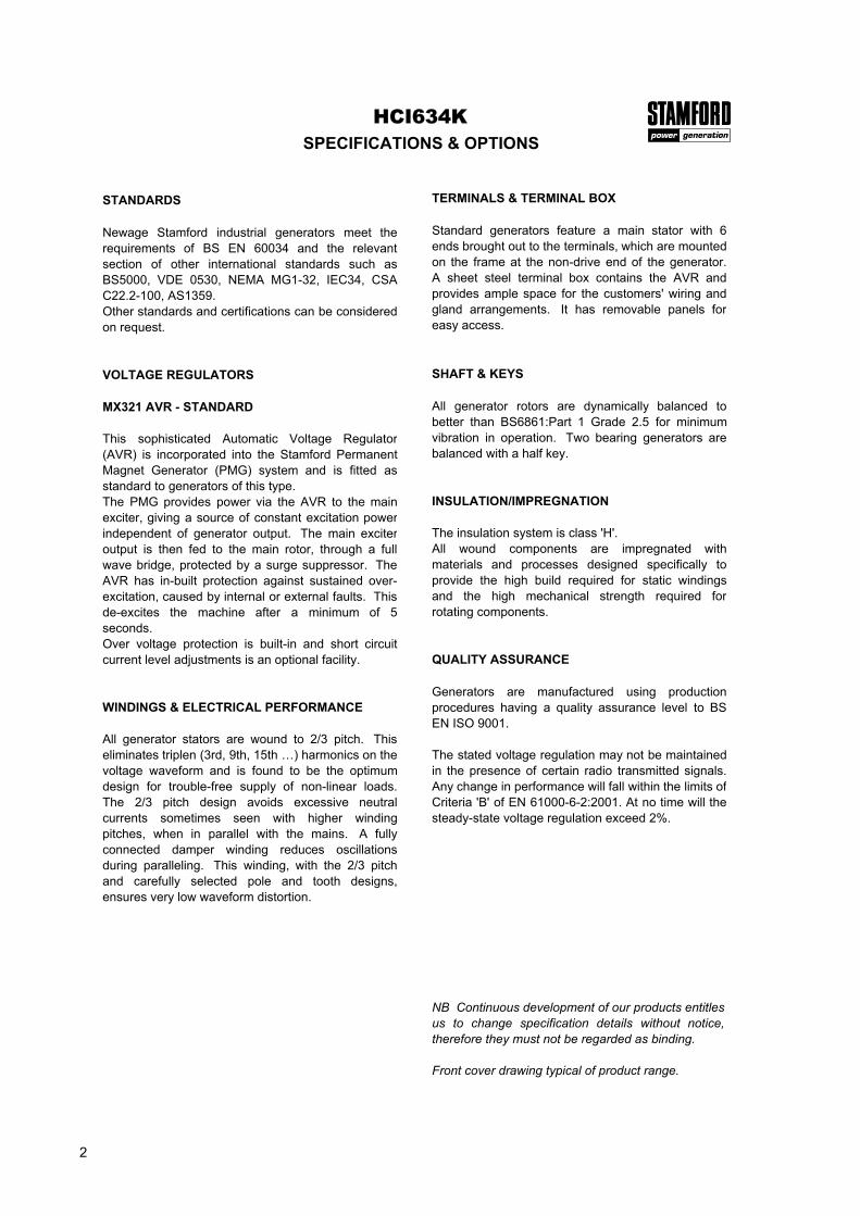
HCI634KSPECIFICATIONS & OPTIONS
STANDARDS
Newage Stamford industrial generators meet therequirements of BS EN 60034 and the relevantsection of other international standards such asBS5000, VDE 0530, NEMA MG1-32, IEC34, CSAC22.2-100, AS1359.Other standards and certifications can be consideredon request.
VOLTAGE REGULATORS
MX321 AVR - STANDARD
This sophisticated Automatic Voltage Regulator(AVR) is incorporated into the Stamford PermanentMagnet Generator (PMG) system and is fitted asstandard to generators of this type.The PMG provides power via the AVR to the mainexciter, giving a source of constant excitation powerindependent of generator output. The main exciteroutput is then fed to the main rotor, through a fullwave bridge, protected by a surge suppressor. TheAVR has in-built protection against sustained over-excitation, caused by internal or external faults. Thisde-excites the machine after a minimum of 5seconds.Over voltage protection is built-in and short circuitcurrent level adjustments is an optional facility.
WINDINGS & ELECTRICAL PERFORMANCE
All generator stators are wound to 2/3 pitch. Thiseliminates triplen (3rd, 9th, 15th …) harmonics on thevoltage waveform and is found to be the optimumdesign for trouble-free supply of non-linear loads.The 2/3 pitch design avoids excessive neutralcurrents sometimes seen with higher windingpitches, when in parallel with the mains. A fullyconnected damper winding reduces oscillationsduring paralleling. This winding, with the 2/3 pitchand carefully selected pole and tooth designs,ensures very low waveform distortion.
TERMINALS & TERMINAL BOX
Standard generators feature a main stator with 6ends brought out to the terminals, which are mountedon the frame at the non-drive end of the generator.A sheet steel terminal box contains the AVR andprovides ample space for the customers' wiring andgland arrangements. It has removable panels foreasy access.
SHAFT & KEYS
All generator rotors are dynamically balanced tobetter than BS6861:Part 1 Grade 2.5 for minimumvibration in operation. Two bearing generators arebalanced with a half key.
INSULATION/IMPREGNATION
The insulation system is class 'H'.All wound components are impregnated withmaterials and processes designed specifically toprovide the high build required for static windingsand the high mechanical strength required forrotating components.
QUALITY ASSURANCE
Generators are manufactured using productionprocedures having a quality assurance level to BSEN ISO 9001.
The stated voltage regulation may not be maintainedin the presence of certain radio transmitted signals.Any change in performance will fall within the limits ofCriteria 'B' of EN 61000-6-2:2001. At no time will thesteady-state voltage regulation exceed 2%.
NB Continuous development of our products entitlesus to change specification details without notice,therefore they must not be regarded as binding.
Front cover drawing typical of product range.
2

CONTROL SYSTEM SEPARATELY EXCITED BY P.M.G.
A.V.R. MX321
VOLTAGE REGULATION ± 0.5 %
SUSTAINED SHORT CIRCUIT
INSULATION SYSTEM
PROTECTION
RATED POWER FACTOR
STATOR WINDING
WINDING PITCH
WINDING LEADS
STATOR WDG. RESISTANCE
ROTOR WDG. RESISTANCE
R.F.I. SUPPRESSION BS EN 61000-6-2 & BS EN 61000-6-4,VDE 0875G, VDE 0875N. refer to factory for others
WAVEFORM DISTORTION NO LOAD < 1.5% NON-DISTORTING BALANCED LINEAR LOAD < 5.0%
MAXIMUM OVERSPEED 2250 Rev/Min
BEARING DRIVE END
BEARING NON-DRIVE END
1 BEARING 2 BEARING
WEIGHT COMP. GENERATOR
WEIGHT WOUND STATOR
WEIGHT WOUND ROTOR
WR² INERTIA
SHIPPING WEIGHTS in a crate
PACKING CRATE SIZE
TELEPHONE INTERFERENCE
COOLING AIR
VOLTAGE STAR 380/220 400/231 415/240 440/254 416/240 440/254 460/266 480/277
VOLTAGE DELTA 220 230 240 254 240 254 266 277
kVA BASE RATING FOR REACTANCE VALUES 1110 1110 1110 1110 1275 1338 1388 1438
Xd DIR. AXIS SYNCHRONOUS 2.78 2.51 2.33 2.07 3.20 3.00 2.85 2.71X'd DIR. AXIS TRANSIENT 0.22 0.20 0.19 0.17 0.26 0.24 0.23 0.22X''d DIR. AXIS SUBTRANSIENT 0.16 0.14 0.13 0.12 0.18 0.17 0.16 0.15Xq QUAD. AXIS REACTANCE 1.63 1.47 1.37 1.21 1.88 1.76 1.67 1.59X''q QUAD. AXIS SUBTRANSIENT 0.23 0.21 0.20 0.17 0.27 0.25 0.24 0.23XL LEAKAGE REACTANCE 0.08 0.07 0.06 0.06 0.09 0.08 0.08 0.07X2 NEGATIVE SEQUENCE 0.22 0.20 0.19 0.17 0.26 0.24 0.23 0.22X0 ZERO SEQUENCE 0.03 0.02 0.02 0.02 0.03 0.03 0.03 0.03
REACTANCES ARE SATURATED VALUES ARE PER UNIT AT RATING AND VOLTAGE INDICATED
T'd TRANSIENT TIME CONST.T''d SUB-TRANSTIME CONST.T'do O.C. FIELD TIME CONST.Ta ARMATURE TIME CONST.SHORT CIRCUIT RATIO
0.1850.0253.4
0.049
HCI634K
1.614 m³/sec 3420 cfm 1.961 m³/sec 4156 cfm
50 Hz
THF<2%
60 Hz
TIF<50
2581 kg
2601kg
0.8
IP23
CLASS H
BALL. 6317 (ISO)
REFER TO SHORT CIRCUIT DECREMENT CURVES (page 7)
WINDING 312
With 4% ENGINE GOVERNING
1/Xd
DOUBLE LAYER LAP
2.36 Ohms at 22°C
0.002 Ohms PER PHASE AT 22°C STAR CONNECTED
6
TWO THIRDS
1294 kg
2541 kg
1294 kg
BALL. 6224 (ISO)
1093 kg 1048 kg
25.9823 kgm2
194 x 92 x 147(cm)
26.5295 kgm2
2622kg
194 x 92 x 147(cm)
3

Winding 312HCI634K
THREE PHASE EFFICIENCY CURVES
50Hz
4

Winding 312HCI634K
THREE PHASE EFFICIENCY CURVES
60Hz
5

HCI634KWinding 312
Locked Rotor Motor Starting Curve
0
5
10
15
20
25
30
0 200 400 600 800 1000 1200 1400 1600 1800 2000 2200 2400 2600 2800 3000 3200LOCKED ROTOR kVA
PER
CEN
T TR
AN
SIEN
T VO
LTA
GE
DIP
.
346V 380V 400V 415V 440V
0
5
10
15
20
25
30
0 400 800 1200 1600 2000 2400 2800 3200 3600 4000LOCKED ROTOR kVA
PER
CEN
T TR
AN
SIEN
T VO
LTA
GE
DIP
.
380V 416V 440V 460V 480V
50Hz
60Hz
6
3-phase 2-phase L-L 1-phase L-NVoltage Factor Voltage Factor x 1.00 x 0.87 x 1.30
380v X 1.00 416v x 1.00 x 1.00 x 1.80 x 3.20400v X 1.07 440v x 1.06 x 1.00 x 1.50 x 2.50415v X 1.12 460v x 1.12 10 sec. 5 sec. 2 sec.440v X 1.18 480v x 1.17
Minimum
HCI634K
50Hz 60Hz
The sustained current value is constant irrespectiveof voltage level
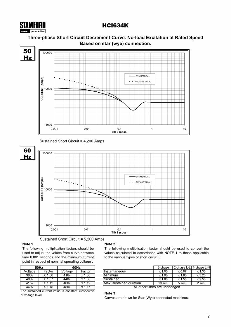
Three-phase Short Circuit Decrement Curve. No-load Excitation at Rated SpeedBased on star (wye) connection.
Max. sustained durationAll other times are unchanged
Instantaneous
Sustained
Sustained Short Circuit = 4,200 Amps
Sustained Short Circuit = 5,200 AmpsNote 1The following multiplication factors should beused to adjust the values from curve betweentime 0.001 seconds and the minimum currentpoint in respect of nominal operating voltage :
Note 2The following multiplication factor should be used to convert thevalues calculated in accordance with NOTE 1 to those applicableto the various types of short circuit :
Note 3Curves are drawn for Star (Wye) connected machines.
50Hz
60Hz
1000
10000
100000
0.001 0.01 0.1 1 10TIME (secs)
CUR
RENT
(Am
ps) SYMMETRICAL
ASYMMETRICAL
1000
10000
100000
0.001 0.01 0.1 1 10TIME (secs)
CUR
RENT
(Am
ps) SYMMETRICAL
ASYMMETRICAL
7
Class - Temp Rise
Star (V) 380 400 415 440 380 400 415 440 380 400 415 440 380 400 415 440
Delta (V) 220 230 240 254 220 230 240 254 220 230 240 254 220 230 240 254
kVA 1000 1018 1000 1000 1110 1130 1110 1110 1180 1190 1180 1180 1220 1230 1220 1220
kW 800 814 800 800 888 904 888 888 944 952 944 944 976 984 976 976
Efficiency (%) 95.6 95.7 95.8 95.9 95.4 95.5 95.6 95.7 95.2 95.3 95.5 95.6 95.1 95.2 95.4 95.5
kW Input 837 851 835 834 931 947 929 928 992 999 988 987 1026 1034 1023 1022
Star (V) 416 440 460 480 416 440 460 480 416 440 460 480 416 440 460 480
Delta (V) 240 254 266 277 240 254 266 277 240 254 266 277 240 254 266 277
kVA 1188 1238 1275 1313 1275 1338 1388 1438 1350 1413 1469 1525 1400 1463 1519 1575
kW 950 990 1020 1050 1020 1070 1110 1150 1080 1130 1175 1220 1120 1170 1215 1260
Efficiency (%) 95.6 95.6 95.7 95.7 95.4 95.5 95.5 95.5 95.3 95.3 95.4 95.4 95.1 95.2 95.3 95.3
kW Input 994 1036 1066 1098 1069 1121 1163 1205 1133 1186 1232 1279 1178 1229 1275 1322
14 18 21 24
25.4 15.87 0 0
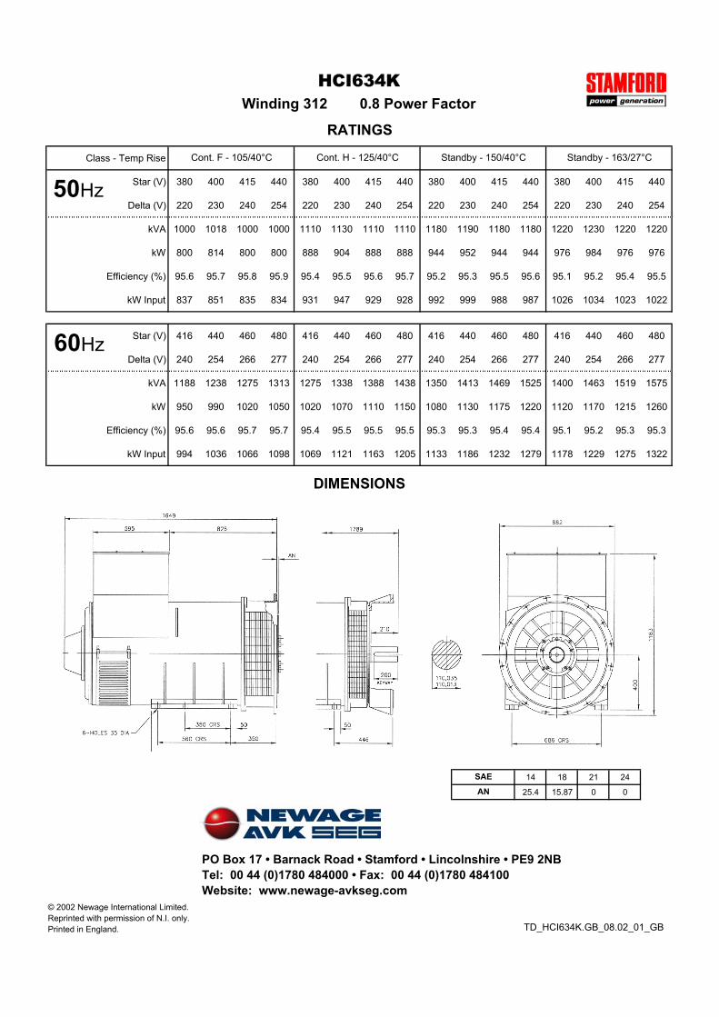
HCI634K
Cont. F - 105/40°C Cont. H - 125/40°C Standby - 150/40°C Standby - 163/27°C
Winding 312 0.8 Power Factor
RATINGS
TD_HCI634K.GB_08.02_01_GB
SAE
AN
DIMENSIONS
50Hz
60Hz
PO Box 17 • Barnack Road • Stamford • Lincolnshire • PE9 2NBTel: 00 44 (0)1780 484000 • Fax: 00 44 (0)1780 484100Website: www.newage-avkseg.com
© 2002 Newage International Limited.Reprinted with permission of N.I. only.Printed in England.
50Hz
60Hz

New InteliGen NT
GENERAL PURPOSE COMPACT GEN–SET CONTROLLER
LEADER IN GEN–SETCOMMUNICATION SOLUTION
ComAp is a member of AMPS(The Association of Manufacturers of Power generating Systems).
ComAp products meet the highest standards, with every stage of production undertaken in accordance with the ISO certification obtained in 1998.
Description
New Technology InteliGen is a
comprehensive controller for both
single and multiple gen-sets operating
in standby or parallel modes. Compact
construction is optimized for these
purposes; various HW modifications
allow the customer to select the
optimum type for a particular application.
Built-in synchronizer and digital
isochronous load sharer allow total
integrated solution for gen-sets in
standby, island parallel or mains parallel.
Native cooperation of up to 32 gen-sets
is a standard feature.
InteliGenNT supports many standard ECU
types and is especially designed to easily
integrate new ones.
Powerful graphic display with user-friendly
control allows even new users to find
quickly the required information.
ComAp is open to various customized
firmware solutions.
Benefits Support of engines with ECU
(Electronic Control Unit)
Excellent configurability allows
matching exactly the customer’s
needs
Complete integrated gen-set solution
and signal sharing via CAN bus
– minimum external components
needed
Many communication options – easy
remote supervising and servicing
Perfect price/performance ratio
Gen-set performance log for easy
problem tracing

New InteliGen NT
GENERAL PURPOSE COMPACT GEN–SET CONTROLLER
InteliGenNT
Support of engines with ECU (J1939, ModBus and other proprietary interfaces); alarm codes displayed in text form
AMF function
Automatic synchronizing and power control (via speed governor or ECU)
Baseload, Import/Export
Peak shaving
Voltage and PF control (AVR)
Generator measurement: U, I, Hz, kW, kVAr, kVA, PF, kWh, kVAhr
Mains measurement: U, I, Hz, kW, kVAr, PF
Inputs and outputs configurable for various customer needs
RS232/RS485 interface with ModBus support; Analog/GSM/ISDN/CDMA modem support; SMS messages; ECU ModBus interface
Event-based history (up to 500 records) with customer-selectable list of stored values; RTC; statistic values
Integrated PLC programmable functions
Interface to remote display unit (IG-Display)
Dimensions 180x120 mm (front panel)
Sealed to IP65
InteliGenNTC
All items from InteliGenNT Features list
+ Selectable measurement ranges for AC voltages and currents – 120 / 277 V, 0-1 / 0-5 A
+ Secondary RS232/RS485 interface with the same features as the primary one; additionally, the RS485 converter is isolated
+ USB 2.0 slave interface
Integrated fixed and configurable protections 3 phase integrated generator protections
(U + f)
IDMT overcurrent + Shortcurrent
protection
Overload protection
Reverse power protection
Earth fault protection
3 phase integrated mains protections
(U + f)
Vector shift protection
All binary/analogue inputs free
configurable for various protection
types: HistRecOnly / Alarm Only /
Warning / Off load / Slow stop /
BreakerOpen&Cooldown / Shutdown /
Mains protect / Sensor fail
Additional 160 programmable protections
configurable for any measured value to
create customer-specific protections
Features

PC
PC
IG-DISPLAY
MODEMPC MODEM
IS-BIN16/8
�������
I-CB/XX
IGS-PTM
IGL-RA15
I-CB/XX
IGS-PTM
IGL-RA15
I-AOUT8
I-CB/XXI-CB/XXI-CB/XX
IS-BIN16/8
�������
IS-BIN16/8
��������������
ENGINE
12 BINARY
OUTPUTS
(OPEN
COLLECTOR)
3 ANALOG
INPUTS
GENERATOR
MAINSIG-NT/IG-NTC
EARTH FAULT
CURRENT
CURRENTVO
LTAGE
SG O
UT
AVRi OUT
INTER-CONTROLLER
& MONITORING
CAN2
RS 232(1)
INTERFACERS485(1)IG-DISPLAY
or CONVERTER
forRS232(1)
RS232/RS485(2)
INTERFACE
(IG-NTC only)
USB 12 BINARY INPUTS
EXTENSION
MODULES
CAN1
POWER SUPPLY
8 TO 36 VDC+ -
CURRENTVO
LTAGE
MEASUREM
ENT
12
3
GENERATOR
DIESEL/GAS ENGINE
Starter
Fuel Solenoid
LOAD
1ph3ph3ph
Generator C. B. Control
1ph3ph
Mains C. B. Control
MAINS
10
IGS-NT-LSM+PMS dongle:
POWER MANAGEMENT
DIGITAL LOAD SHARING
DIGITAL VAr SHARING
Protocol depends on ECU type
CAN J1939
Proprietary
ECU coms.
(MDEC/M
TU,
CCM/CAT, ...)
Proprietary ECU coms.
(MODBUS/CUMMINS, ...)
IG-IB
I-LB
IG-IB
21
3
3
21 ECU
SPEED GOVERNOR AVR
AVRi
Extension features
up to 10x IS-AIN8 (8 analogue
configurable inputs; 2 or 3 wire
resistive sensors; voltage, current
sensors; thermocouples)
up to 6x IS-BIN16/8 (16 binary inputs,
8 binary outputs; galvanic separated
I/O)
up to 4x I-AOUT8 (8 analogue
configurable outputs)
up to 4x IGS-PTM (4 analogue inputs,
1 analogue outputs; 8 binary inputs,
8 binary outputs)
up to 4x IGL-RA15 (15 green /
amber / red LED indicators)
I-CB interface to electronic engine
control units not compatible with
protocol J1939 (e.g. MDEC/MTU,
CCM/CAT)
IG-Display; graphical remote display;
distance from the controller up to
1 km; (LT) (GC) (Marine) modifications
available
Communicationextension features
IG-IB (Ethernet/Internet
communication support; multiple gen-
set control via Internet; active e-mails
on gen-set failure; Internet dial-up /
callback function)
I-LB/I-LB+ (direct, modem or USB
(I-LB+ version only)connection;
control of multiple gen-sets; RS485 /
ModBus support for direct connection;
Analog/GSM/ISDN/CDMA modem
support; modem callback function)
I-CR (CAN Repeater module; allows
an extension of the standard CAN bus
length)
InteliMonitor – free PC SCADA
software for supervision of single or
multiple controllers (IG/IS-NT, IG, IS,
ID); configurable site structure; easy
site overview, common history log;
direct / modem / Internet connection
GenConfig – free configuration tool
for IG/IS-NT controllers; allows full
configuration of an NT controller and
it‘s peripherals
Upgrade kit
IGS-NT-LSM+PMS dongle:
Enables multiple isolated parallel or
multiple parallel with mains operation
(with CAN bus)
Digital Load Sharing
Digital VAr Sharing
Optimizing number of running
engines: Power management; kW,
kVA or % load based
HW modification codes
Order code IG-NT (LT) (GC) (Marine) or
IG-NTC (LT) (GC) (Marine)
LT = Low Temperature; display equipped with heating foil for operation down to –30°C
GC = Graphical Characters; one additional font (12x12, e.g. Chinese) can be used on the display
Marine = Type approved version for Marine
Features and specification are subject to change without prior notice 2005-11
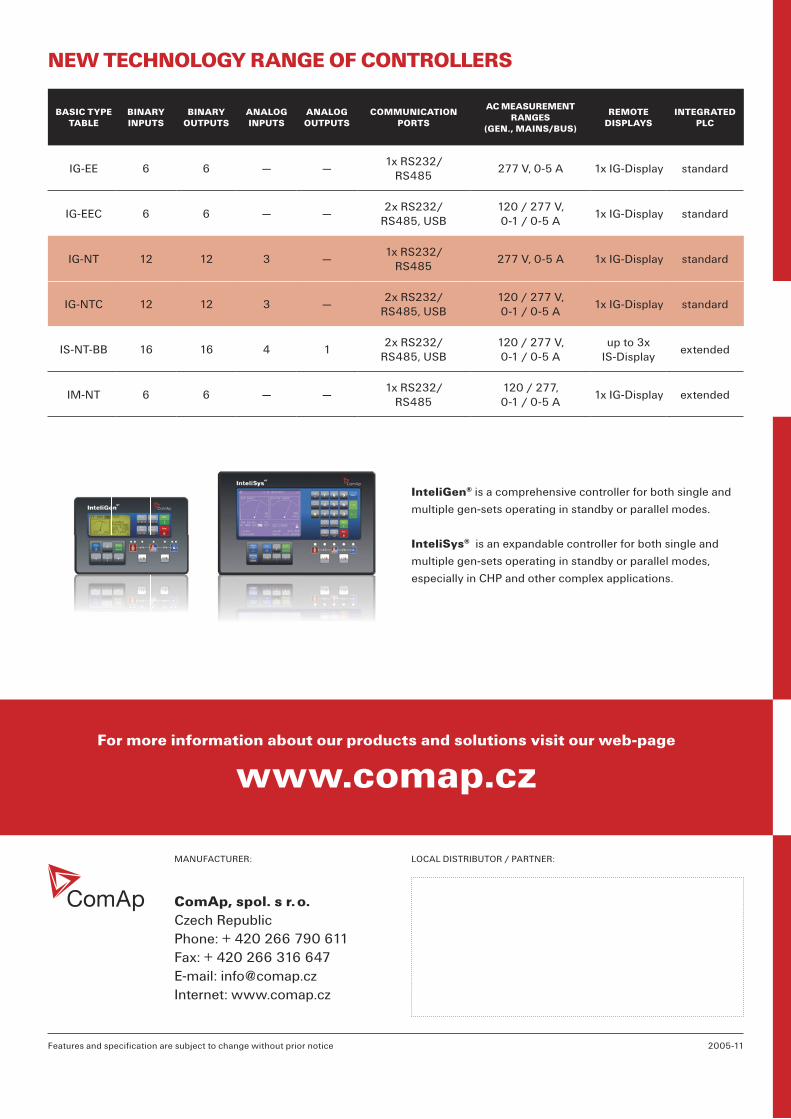
BASIC TYPE TABLE
BINARY INPUTS
BINARY OUTPUTS
ANALOG INPUTS
ANALOG OUTPUTS
COMMUNICATIONPORTS
AC MEASUREMENT RANGES
(GEN., MAINS/BUS)
REMOTEDISPLAYS
INTEGRATEDPLC
IG-EE 6 6 — —1x RS232/
RS485277 V, 0-5 A 1x IG-Display standard
IG-EEC 6 6 — —2x RS232/
RS485, USB120 / 277 V, 0-1 / 0-5 A
1x IG-Display standard
IG-NT 12 12 3 —1x RS232/
RS485277 V, 0-5 A 1x IG-Display standard
IG-NTC 12 12 3 —2x RS232/
RS485, USB120 / 277 V, 0-1 / 0-5 A
1x IG-Display standard
IS-NT-BB 16 16 4 12x RS232/
RS485, USB120 / 277 V, 0-1 / 0-5 A
up to 3x IS-Display
extended
IM-NT 6 6 — —1x RS232/
RS485120 / 277,0-1 / 0-5 A
1x IG-Display extended
ComAp, spol. s r. o.Czech RepublicPhone: + 420 266 790 611 Fax: + 420 266 316 647E-mail: [email protected]: www.comap.cz
MANUFACTURER: LOCAL DISTRIBUTOR / PARTNER:
InteliGen® is a comprehensive controller for both single and
multiple gen-sets operating in standby or parallel modes.
InteliSys® is an expandable controller for both single and
multiple gen-sets operating in standby or parallel modes,
especially in CHP and other complex applications.
www.comap.czFor more information about our products and solutions visit our web-page
NEW TECHNOLOGY RANGE OF CONTROLLERS


![Untitled-2 [suntracbatteries.com]suntracbatteries.com/suntrac.pdf · capacity 12v 20ah 12v 40ah 12v 60ah 12v b40ah 12v b60ah 12v b80ah 12v biooah 12v 80ah 12v iooah 12v 130ah 12v](https://static.fdocuments.in/doc/165x107/603efb7aa12c32391f5484d1/untitled-2-capacity-12v-20ah-12v-40ah-12v-60ah-12v-b40ah-12v-b60ah-12v-b80ah.jpg)