MODEL lll ‘Z’ LINKER OPERATION AND MAINTENANCE MANUAL · model lll ‘z’ linker operation and...
49
MODEL lll ‘Z’ LINKER OPERATION AND MAINTENANCE MANUAL US PATENT NUMBERS 4420856 & 4418447 1
-
Upload
nguyendiep -
Category
Documents
-
view
216 -
download
1
Transcript of MODEL lll ‘Z’ LINKER OPERATION AND MAINTENANCE MANUAL · model lll ‘z’ linker operation and...

MODEL lll
‘Z’ LINKER
OPERATION AND MAINTENANCE
MANUAL
US PATENT NUMBERS4420856 & 4418447
1

CONTENTS
LIST OF ILLUSTRATIONS ..................................................................................................... 4-5
SECTION I INTRODUCTION 1.1 General ................................................................................................................ 6 1.2 Features .............................................................................................................. 6 1.3 About This Manual .............................................................................................. 7
SECTION II DESCRIPTION 2.1 General ................................................................................................................ 8 2.2 Assemblies - Component Parts ........................................................................... 8 2.3 Disc Assembly ...................................................................................................... 9 2.4 Gearmotor .......................................................................................................... 11 2.5 Disc Guard ......................................................................................................... 12 2.6 Switches ............................................................................................................. 13 2.7 Safety Limit Switch............................................................................................. 13 2.8 Pedestal ............................................................................................................. 14 2.9 Grease Fittings................................................................................................... 14 2.10 Guide Roll Bracket Sub-Assembly ..................................................................... 15 2.11 Linking Head Sub-Assembly (Linker)................................................................. 16 2.12 Cams .................................................................................................................. 17 2.13 Outboard Supports............................................................................................. 18 2.14 Components....................................................................................................... 18 2.15 Electrical Power Plug ......................................................................................... 18
SECTION III INSTALLATION 3.1 Receiving ........................................................................................................... 19 3.2 Removal ............................................................................................................. 19 3.3 Inspection........................................................................................................... 20 3.4 Installation .......................................................................................................... 20 3.4.1 Mounting ................................................................................................. 20 3.4.2 Conveyors ............................................................................................... 21
SECTION IV OPERATION 4.1 Procedure .......................................................................................................... 23
2

CONTENTS
SECTION V MAINTENANCE 5.1 General ............................................................................................................... 24 5.2 Maintenance Schedule ...................................................................................... 24 5.3 Linking Head Sub-Assemblies Repair or Adjustment ........................................ 25 5.3.1 Disassembly ............................................................................................ 26 5.3.2 Insert Replacement ................................................................................ 27 5.4 Adjustment ..........................................................................................................27 5.5 Maintenance of Other Parts ................................................................................27
SECTION VI TROUBLESHOOTING 6.1 Parts ................................................................................................................... 28 6.2 Tools ................................................................................................................... 28 6.3 Identification ....................................................................................................... 28 6.4 Safety Precautions ............................................................................................. 28 6.5 Authorized Personnel......................................................................................... 28 6.6 Tables................................................................................................................. 28 Table 6-1 Electrical Troubleshooting ............................................................ 29-32 Table 6-2 Mechanical Troubleshooting ........................................................ 33-36
SECTION VII PARTS LIST 7.1 Ordering Parts.................................................................................................... 37 7.2 Parts Not Illustrated ........................................................................................... 37 7.3 Parts List ....................................................................................................... 38-42 7.4 Addendum ......................................................................................................... 43
3

LIST OF ILLUSTRATIONS
Figure 1-1 Nitta “Z” Linker Machine ........................................................................................7
Figure 2-1 Nitta “Z” Linker (front view) ....................................................................................8
Figure 2-2 Disc Assembly .........................................................................................................9
Figure 2-3 Linking Head Sub-Assembly ...................................................................................9
Figure 2-4 Cams .....................................................................................................................10
Figure 2-5 Gearmotor Location ..............................................................................................11
Figure 2-6 Disc Guard ............................................................................................................12
Figure 2-7 Disc Guard in Raised Position ..............................................................................12
Figure 2-8 Switch Wiring Diagram ..........................................................................................13
Figure 2-9 Detail of Safety Switch in Closed Position ............................................................13
Figure 2-10 Detail of Safety Switch in Open Position ...............................................................13
Figure 2-11 Pedestal, Set-screw Hole, and Lubrication Fitting .................................................... 14
Figure 2-12 Guide Roll Bracket Sub-Assembly ........................................................................15
Figure 2-13 Linking Head Sub-Assembly .................................................................................16
Figure 2-14 Linking Head Sub-Assembly in relation to Mounting Discs and Cams ................16
Figure 2-15 Cams and Linking Head Sub-Assembly................................................................17
Figure 2-16 View of Closed and Open Linking Head Sub-Assembly .......................................17
Figure 2-17 Power Plug ............................................................................................................18
4
LIST OF ILLUSTRATIONS
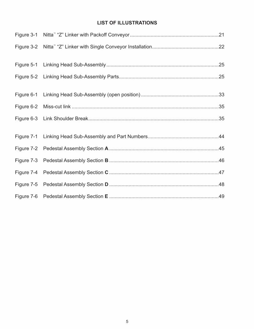
Figure 3-1 Nitta “Z” Linker with Packoff Conveyor ................................................................21
Figure 3-2 Nitta “Z” Linker with Single Conveyor Installation ................................................22
Figure 5-1 Linking Head Sub-Assembly .................................................................................25
Figure 5-2 Linking Head Sub-Assembly Parts........................................................................25
Figure 6-1 Linking Head Sub-Assembly (open position) ........................................................33
Figure 6-2 Miss-cut link ..........................................................................................................35
Figure 6-3 Link Shoulder Break ..............................................................................................35
Figure 7-1 Linking Head Sub-Assembly and Part Numbers ...................................................44
Figure 7-2 Pedestal Assembly Section A ...............................................................................45
Figure 7-3 Pedestal Assembly Section B ...............................................................................46
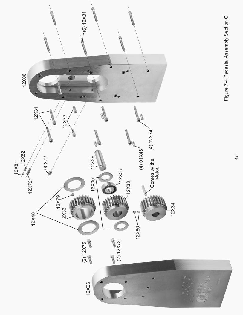
Figure 7-4 Pedestal Assembly Section C ...............................................................................47
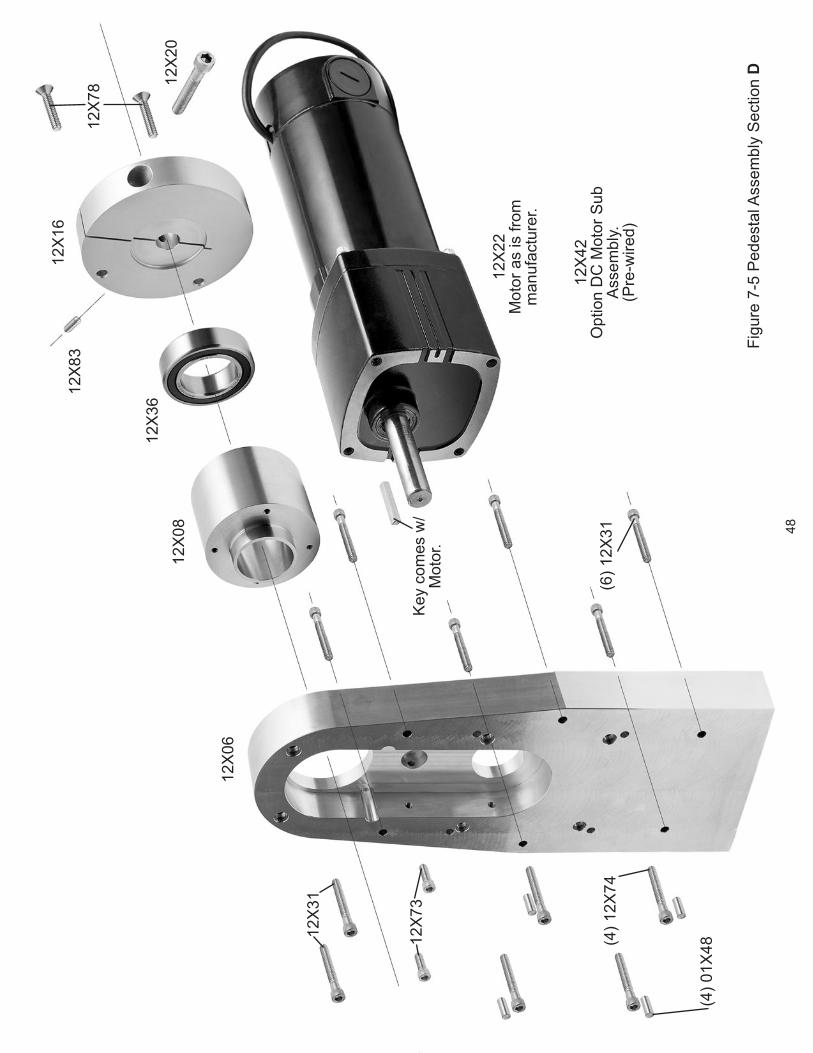
Figure 7-5 Pedestal Assembly Section D ...............................................................................48
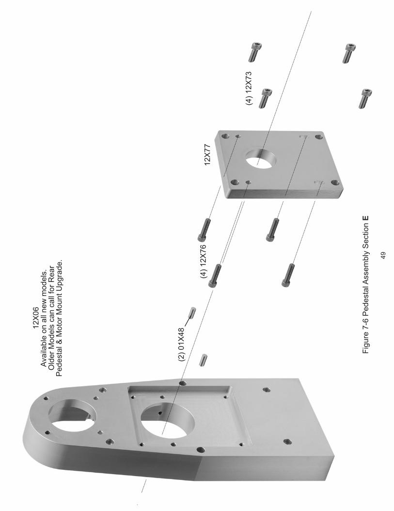
Figure 7-6 Pedestal Assembly Section E ...............................................................................49
5

INTRODUCTIONSECTION I
1.1 GENERAL
The NITTA “Z” Linker is a unique machine designed for use by Meat Packers in the sausage manufacturing industry. Basically, the machine forms and cuts individual links from a continuous stuffed length of casing (as shown in Figure 1-1). Portability, light weight, and high production at low cost are key elements of the NITTA “Z” Linker.
1.2 FEATURES
In addition to portability and low production cost, the NITTA “Z” Linker also has these features:
Safe, reliable operation - by one person•
Simplified ‑highspeedproduction (Up to•600 four inch links per minute)
Small size - 20 x 20 x 26 inches •(approximate)
Low noise level•
USDA accepted•
Linking Head Sub-Assemblies•
Easy mounting - positioning•
Easily removable components•
Reliable totally enclosed gearmotor - UL •approved
Simplified maintenance, clean‑up and•sanitizing
Operates in cold storage environment•
Built-in safety features•
Continuous or intermittent operation•
Self sharpening cutters•
Minimum vibration•
Virtually eliminates miss-cuts•
Absolute minimum of shoulder breaks•
Handles NITTA casing sizes 13 to 32 mm•
Link lengths consistently uniform•
Link length size can be changed within 10 •to 15 minutes
6

Figure 1-1 NITTAModel lll Z Linker.
1.3 ABOUT THIS MANUAL
This manual is divided into eight sections for easy reference to a particular part or subject. Please read the manual in its entirety to understand the operation of the machine and its function. Refer to Section III prior to installing the machine.
7
DESCRIPTIONSECTION II
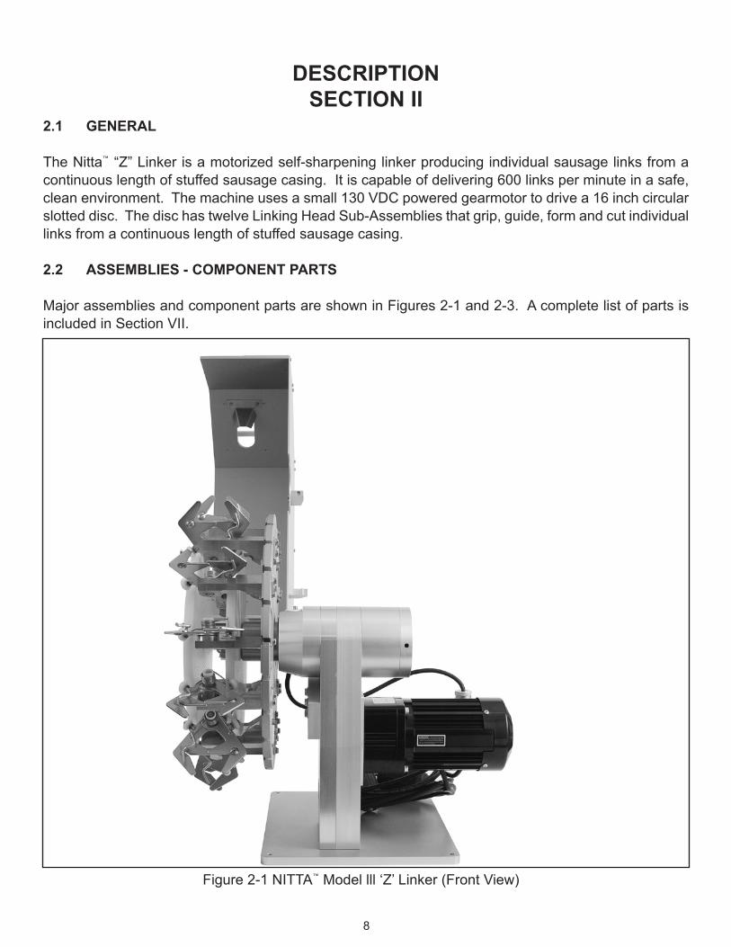
2.1 GENERAL
The Nitta “Z” Linker is a motorized self-sharpening linker producing individual sausage links from a continuous length of stuffed sausage casing. It is capable of delivering 600 links per minute in a safe, clean environment. The machine uses a small 130 VDC powered gearmotor to drive a 16 inch circular slotted disc. The disc has twelve Linking Head Sub-Assemblies that grip, guide, form and cut individual links from a continuous length of stuffed sausage casing.
2.2 ASSEMBLIES ‑ COMPONENT PARTS
Major assemblies and component parts are shown in Figures 2-1 and 2-3. A complete list of parts is included in Section VII.
Figure 2-1 NITTA Model lll ‘Z’ Linker (Front View)
8
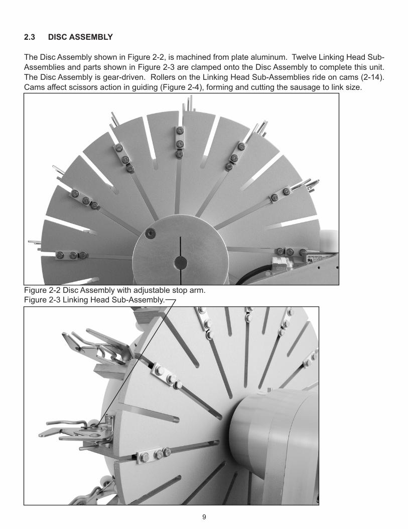
2.3 DISC ASSEMBLY
The Disc Assembly shown in Figure 2-2, is machined from plate aluminum. Twelve Linking Head Sub-Assemblies and parts shown in Figure 2-3 are clamped onto the Disc Assembly to complete this unit. The Disc Assembly is gear-driven. Rollers on the Linking Head Sub-Assemblies ride on cams (2-14). Cams affect scissors action in guiding (Figure 2-4), forming and cutting the sausage to link size.
Figure 2-2 Disc Assembly with adjustable stop arm.Figure 2-3 Linking Head Sub-Assembly.
9

Figure 2-4 Cams(Refer to 2.12 for more information on cams and their function.)
CAMS
10
Cut/drop point maximum closure.
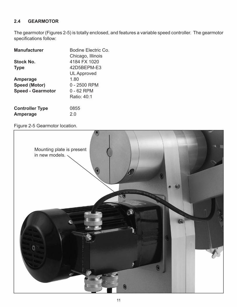
2.4 GEARMOTOR
The gearmotor (Figures 2-5) is totally enclosed, and features a variable speed controller. The gearmotor specificationsfollow:
Manufacturer Bodine Electric Co. Chicago, IllinoisStock No. 4184 FX 1020Type 42D5BEPM-E3 UL ApprovedAmperage 1.80 Speed (Motor) 0 - 2500 RPMSpeed ‑ Gearmotor 0 - 62 RPM Ratio: 40:1
Controller Type 0855Amperage 2.0
Figure 2-5 Gearmotor location.
Mounting plate is present in new models.
11
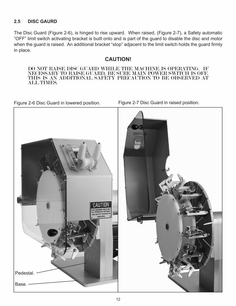
2.5 DISC GAURD
The Disc Guard (Figure 2-6), is hinged to rise upward. When raised, (Figure 2-7), a Safety automatic “OFF” limit switch activating bracket is built onto and is part of the guard to disable the disc and motor whentheguardisraised.Anadditionalbracket“stop”adjacenttothelimitswitchholdstheguardfirmlyin place.
CAUTION! DO NOT RAISE DISC GUARD WHILE THE MACHINE IS OPERATING. IF
NECESSARY TO RAISE GUARD, BE SURE MAIN POWER SWITCH IS OFF. THIS IS AN ADDITIONAL SAFETY PRECAUTION TO BE OBSERVED AT ALL TIMES.
Figure 2-7 Disc Guard in raised position.Figure 2-6 Disc Guard in lowered position.
Pedestal.
Base.
12

2.6 SWITCHES
A control box mounted “on-off” switch is the main control unit for the machine. The switch wiring is shown in Figure 2-8. Enclosing wiring is through the control box to the gear-motor, to stop and start the machine. An interlock through the safety limit switch disables the main control switch when the Disc Guard is in a raised position.
2.7 SAFETY LIMIT SWITCH
The Safety Limit Switch (Figure 2-9 & 2-10), is a micro switch designed to stop the gearmotor when the Disc Guard is raised. Refer to paragraph 2.5 for additional data.
Figure 2-8 Switch Wiring Diagram.NOTE: Safety Switch as shown is normally in open position when guard is up.
Figure 2-9 Detail of safety switch in closed position.
Figure 2-10 Detail of safety switch in open position.
Safety Switches
13

2.8 PEDESTAL
The aluminum pedestal (shown in Figure 2-11) is primarily the base for bearings, gears and shafts. A four hole screw mounted bottom section holds the pedestal to a rectangular aluminum base plate that supports the machine.
2.9 GREASE FITTINGS
There isonegreasefitting installedon themachineasshown inFigure2‑11. Refer toSectionV forlubricationandgreasespecifications.Pleasenotetheventscrewshouldberemovedbeforelubrication.
Figure 2-11 Pedestal, Set-screw Hole, and Lubrication Fitting.
Set-screw hole.
Lubricationfitting.
14
Lubricationoverflow/ventscrew.
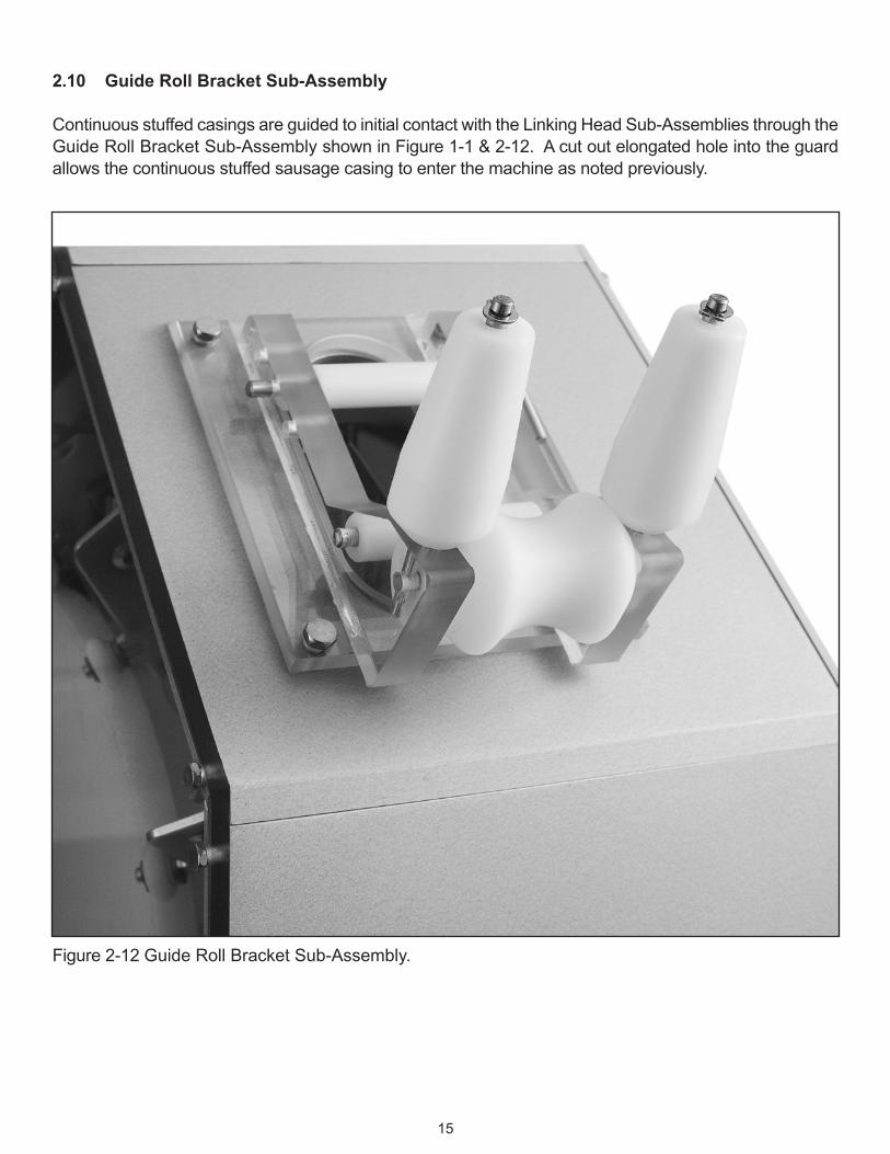
2.10 Guide Roll Bracket Sub‑Assembly
Continuous stuffed casings are guided to initial contact with the Linking Head Sub-Assemblies through the Guide Roll Bracket Sub-Assembly shown in Figure 1-1 & 2-12. A cut out elongated hole into the guard allows the continuous stuffed sausage casing to enter the machine as noted previously.
Figure 2-12 Guide Roll Bracket Sub-Assembly.
15

2.11 LINKING HEAD SUB‑ASSEMBLY (LINKER)
The Linking Head Sub-Assembly (2-13) is a device used in forming and cutting an individual sausage link from a continuous stuffed sausage casing. Disc mounted on the Linker as shown in Figure 2-3 & 2-14, it performs the essential task of forming and cutting sausage into individual links. Spring loaded “blades” are activated by two rollers riding on two cams (Figure 2-14). Rotation of the disc and cam action on the rollers guides, forms and cuts as noted (2-16). Twelve Linking Head Sub-Assemblies are bolted onto a retainer mounted on the slotted disc in a pre-determined located spaced equally around the disc. The cutters are hardened stainless steel self sharpening inserts.
Figure 2-13 Linking Head Sub-Assembly.
Figure 2-14 Linking Head Sub-Assembly in relationship to Mounting Discs and Cams.
Rollers.
16

2.12 CAMS
The cams are non-rotating solid nylon specially contoured discs (Figure 2-4 and 2-11). Each cam is designedtoproducea“specific”linklength.Fastenersholdthecamsinpositionwhilethemachineisoperating.
Figure 2-15 Cams and Linking Head Sub-Assembly.
Figure 2-16 View of Closed and Open Linking Head Sub-Assembly.
Open Linking Head Sub-Assembly.
Closed Linking Head Sub-Assembly.
Roller Guides.
Cams.
Cams.
17
2.13 OUTBOARD SUPPORTS
Outboardsupportscanbeusedtovaryorfine‑tunelink‑lengthsinordertoinsureclosernet‑weighttolerances, improve count-per-pound and reduce give-away.
2.14 COMPONENTS
Other machine components and parts are listed in Section VII, Parts.
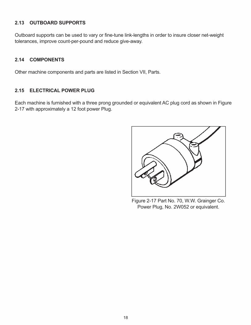
2.15 ELECTRICAL POWER PLUG
Each machine is furnished with a three prong grounded or equivalent AC plug cord as shown in Figure 2-17 with approximately a 12 foot power Plug.
Figure 2-17 Part No. 70, W.W. Grainger Co. Power Plug, No. 2W052 or equivalent.
18
INSTALLATIONSECTION III
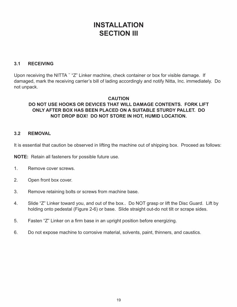
3.1 RECEIVING
Upon receiving the NITTA “Z” Linker machine, check container or box for visible damage. If damaged, mark the receiving carrier’s bill of lading accordingly and notify Nitta, Inc. immediately. Do not unpack.
CAUTION DO NOT USE HOOKS OR DEVICES THAT WILL DAMAGE CONTENTS. FORK LIFT
ONLY AFTER BOX HAS BEEN PLACED ON A SUITABLE STURDY PALLET. DO NOT DROP BOX! DO NOT STORE IN HOT, HUMID LOCATION.
3.2 REMOVAL
It is essential that caution be observed in lifting the machine out of shipping box. Proceed as follows:
NOTE: Retain all fasteners for possible future use.
1. Remove cover screws.
2. Open front box cover.
3. Remove retaining bolts or screws from machine base.
4. Slide “Z” Linker toward you, and out of the box.. Do NOT grasp or lift the Disc Guard. Lift by holding onto pedestal (Figure 2-6) or base. Slide straight out-do not tilt or scrape sides.
5. Fasten“Z”Linkeronafirmbaseinanuprightpositionbeforeenergizing.
6. Do not expose machine to corrosive material, solvents, paint, thinners, and caustics.
19
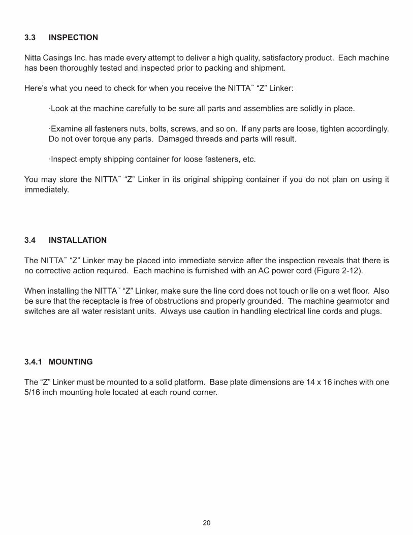
3.3 INSPECTION
Nitta Casings Inc. has made every attempt to deliver a high quality, satisfactory product. Each machine has been thoroughly tested and inspected prior to packing and shipment.
Here’s what you need to check for when you receive the NITTA “Z” Linker:
·Look at the machine carefully to be sure all parts and assemblies are solidly in place.
·Examine all fasteners nuts, bolts, screws, and so on. If any parts are loose, tighten accordingly. Do not over torque any parts. Damaged threads and parts will result.
·Inspect empty shipping container for loose fasteners, etc.
You may store the NITTA “Z” Linker in its original shipping container if you do not plan on using it immediately.
3.4 INSTALLATION
The NITTA “Z” Linker may be placed into immediate service after the inspection reveals that there is no corrective action required. Each machine is furnished with an AC power cord (Figure 2-12).
When installing the NITTA“Z”Linker,makesurethelinecorddoesnottouchorlieonawetfloor.Alsobe sure that the receptacle is free of obstructions and properly grounded. The machine gearmotor and switches are all water resistant units. Always use caution in handling electrical line cords and plugs.
3.4.1 MOUNTING
The “Z” Linker must be mounted to a solid platform. Base plate dimensions are 14 x 16 inches with one 5/16 inch mounting hole located at each round corner.
20

The NITTA “Z” Linker is normally mounted in an upright position. It may, however, be located in a slightly angled position to suit the application. Primary considerations in mounting are:
·Distance from horizontal feed table to feed roll not to exceed 12 inches. See Figure 3-2.
·Accessibility to a suitable electrical outlet or 110 VAC 60 Hz power source.
·Firm support of the machine.
·Accesstoastuffer(filler)andtable.
·Suitable removal of links after discharge from machine (600 links per minute).
·Maintenance of USDA cleanliness standards.
NOTE: Be sure to check out all requirements before operating the machine.
3.4.2 CONVEYORS
Installationsmay include conveyors shown in Figures 3‑1 and 3‑2. Be sure themachine is firmlymounted with no interference in any position.
Figure 3-1 NITTA Z Linker with packoff conveyor.
21

Figure 3-2 NITTA Z Linker with single conveyor installation.
22
OPERATIONSSECTION IV
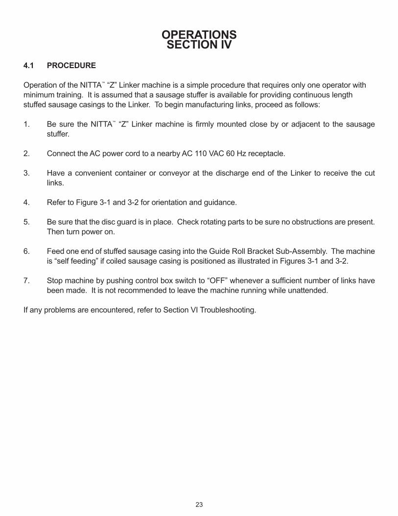
4.1 PROCEDURE
Operation of the NITTA “Z” Linker machine is a simple procedure that requires only one operator with minimum training. It is assumed that a sausage stuffer is available for providing continuous length stuffed sausage casings to the Linker. To begin manufacturing links, proceed as follows:
1. Be sure the NITTA “Z”Linkermachine isfirmlymountedclosebyoradjacent to thesausagestuffer.
2. Connect the AC power cord to a nearby AC 110 VAC 60 Hz receptacle.
3. Have a convenient container or conveyor at the discharge end of the Linker to receive the cut links.
4. Refer to Figure 3-1 and 3-2 for orientation and guidance.
5. Be sure that the disc guard is in place. Check rotating parts to be sure no obstructions are present. Then turn power on.
6. Feed one end of stuffed sausage casing into the Guide Roll Bracket Sub-Assembly. The machine is “self feeding” if coiled sausage casing is positioned as illustrated in Figures 3-1 and 3-2.
7. Stopmachinebypushingcontrolboxswitchto“OFF”wheneverasufficientnumberoflinkshavebeen made. It is not recommended to leave the machine running while unattended.
If any problems are encountered, refer to Section VI Troubleshooting.
23

MAINTENANCESECTION V
5.1 GENERAL
Specificpartsonthemachineshouldberegularlyservicedand/oradjustedtokeepitoperatingsatisfactorily over a long period of time. When maintenance is performed the operator or technician should be familiar with the part or assembly - its function and purpose. Other sections of this manual will help with this procedure. Here is a suggested maintenance schedule that may be followed to assist in maintaining the machine.
CAUTIONBE SURE POWER SWITCH IS “OFF” AND LINE CORD OUT OF WALL OR RECEPTACLE.
5.2 MAINTENANCE SCHEDULE
DAILY
ITEM PROCEDURE
All machine parts that contain residual meat or sausage products. All parts that may be dirty.
Inspect moving parts.
Clean only with USDA approved cleaner.Blow dry.Spray with food grade oil.
Observe caution. Tighten any loose fasteners or parts.
WEEKLY
Lubrication Fitting.
CAM Rollers.
If machine has been running continuously, lubricate fitting,using grease gun (pressure type) sparingly. If machine has had limited use, lubricate monthly (See appendix for recommended lubricant).
Lubricate linking heads with USDA approved lubricant.
MONTHLY
Inspect entire machine.Tighten all fasteners. Replace parts that appear worn. Some machine parts may be repaired, such as Linking Head Sub-Assemblies. See paragraph 5-3.
24
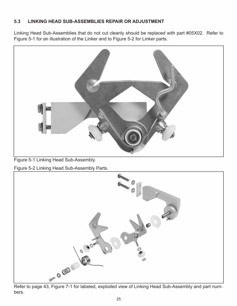
5.3 LINKING HEAD SUB‑ASSEMBLIES REPAIR OR ADJUSTMENT
Linking Head Sub-Assemblies that do not cut cleanly should be replaced with part #05X02. Refer to Figure 5-1 for an illustration of the Linker and to Figure 5-2 for Linker parts.
Figure 5-1 Linking Head Sub-Assembly.
Figure 5-2 Linking Head Sub-Assembly Parts.
Refer to page 43, Figure 7-1 for labeled, exploded view of Linking Head Sub-Assembly and part num-bers.
25

5.3.1 DISASSEMBLY
These instructions show you how to disassemble the linking head Sub-Assembly.
1. Remove torsion spring by grasping the spring, compressing it, and lifting straight out.
2. Remove the machine screw holding the compression spring in the spring holder.
3. Remove spring holder. The spring holder holds the compression spring in place and centers the torsion spring.
4. Remove compression spring.
5. Remove outer (left hand) blade (left hand blade is not interchangeable with right hand blade).
6.RemoveTeflonwasher(.030).
7. Remove other (right hand) blade (right hand blade is not interchangeable with left hand blade).
8. Remove bronze bushing.
9.RemoveTeflonwasher(.015).
10. Reassemble in reverse order
NOTEThe torsion springs keeps rollers on the blades against the stops.
12.Checkallpartsforwear,tensioncompressionandfit.
13. Remove and replace all partsthatdonotconformtofitandfunction.
26

5.3.2 BLADE REPLACEMENT
Complete blade replacement kits are available; part # 05X02.
5.4 ADJUSTMENT
Adjustment of the Nitta “Z” Linker is a precise task that requires careful attention to compression, tension andfit.Whenmakingadjustmentsforthefirsttime,useanadjacentfunctioningLinkingHeadSub‑Assembly as a model. Once the proper adjustments have been made, go on to the next Linking Head Sub-Assembly and repeat the adjustment procedure. If problems develop, refer to the Troubleshooting Section for additional instruction.
5.5 MAINTENANCE OF OTHER PARTS
Other parts, assemblies and components of the machine require practically no maintenance. If additional procedures are required, they will be included in the Addendum Section of this manual.
27

TROUBLESHOOTINGSECTION VI
You should read this section carefully and understand it thoroughly prior to repairing or replacing machine equipment. This section contains tables that identify a problem and show recommended solutions to the problem.
6.1 PARTS
Do not replace parts with anything other than standard Nitta Casings, Inc. equipment. The Parts List in Section VII lists parts and equipment that can be ordered for replacement or used as spares.
6.2 TOOLS
Onlyusethosetoolswhicharespecificallysuitedforthejob.Donotforcefitanythreadedparts.
6.3 IDENTIFICATION
All assembly parts that are removed should be replaced in reverse order of disassembly. Be sure that each part removed is secured in a separate area to avoid loss or improper reassembly. Parts and assemblies noted herein are described in Section II.
6.4 SAFETY PRECAUTIONS
Never troubleshoot the machine while it is energized. Rotating and moving parts are potential hazards if guards are removed. The NITTA “Z” Linker is a safe machine to operate when proper safety precautions are observed. Never change switches, the machine fuse, controller components, or other partswithoutfirstremovingtheAClinecordfromthereceptacleorwallsocket.
6.5 AUTHORIZED PERSONNEL
Onlyauthorizedtechnicians,mechanics,electricians,orotherqualifiedpersonnelshouldbeallowedto repair, service, or maintain the machine.
6.6 TABLES
This section contains two tables, which identify potential electrical and mechanical problems, and gives you step-by-step solutions to those problems.
28

TABLE 6‑1ELECTRICAL TROUBLESHOOTING
PROBLEM SOLUTION
A. Machine does not run when main switch (ON-OFF) is pushed.
STEP 1
Check AC line cord to outlet connection. Be sure that connections are solid and AC power is available. A lamp or circuittesterintheoutletwillindicatecurrentflowornopower.Iftest indicates no power, check utility circuit breaker or fuse. Reset circuit breaker or replace fuse with one of equal amperage.
CAUTION!REMOVE AC LINE CORD FROM WALL OR RECEPTACLE
BEFORE MOVING ON TO STEP 2.
STEP 2Place AC line cord into socket or receptacle. Start machine. If inoperative, check AC line cord continuity with ohm meter. Open machine control box for connections through line cord for this test. Repair or replace faulty wires or AC line cord. Check fuse if machine does not run, proceed to Step 3.
STEP 3a. Check operation of Safety Limit Switch by lifting Disc Guard
slightly until activating bracket just clears the top of switch.
CAUTION!BE CAREFUL NOT TO INSERT FINGERS OR TOOLS NEAR
DISC. MACHINE MAY START AND CAUSE DAMAGE OR INJURY WHEN SWITCH IS ACTIVATED.
b. PushSafetyLimitSwitchseveraltimesusingaflat‑headedscrewdriver. If machine runs, lower Disc Guard and continue operations. If machine does not run with cover closed, turn to the next page.
29
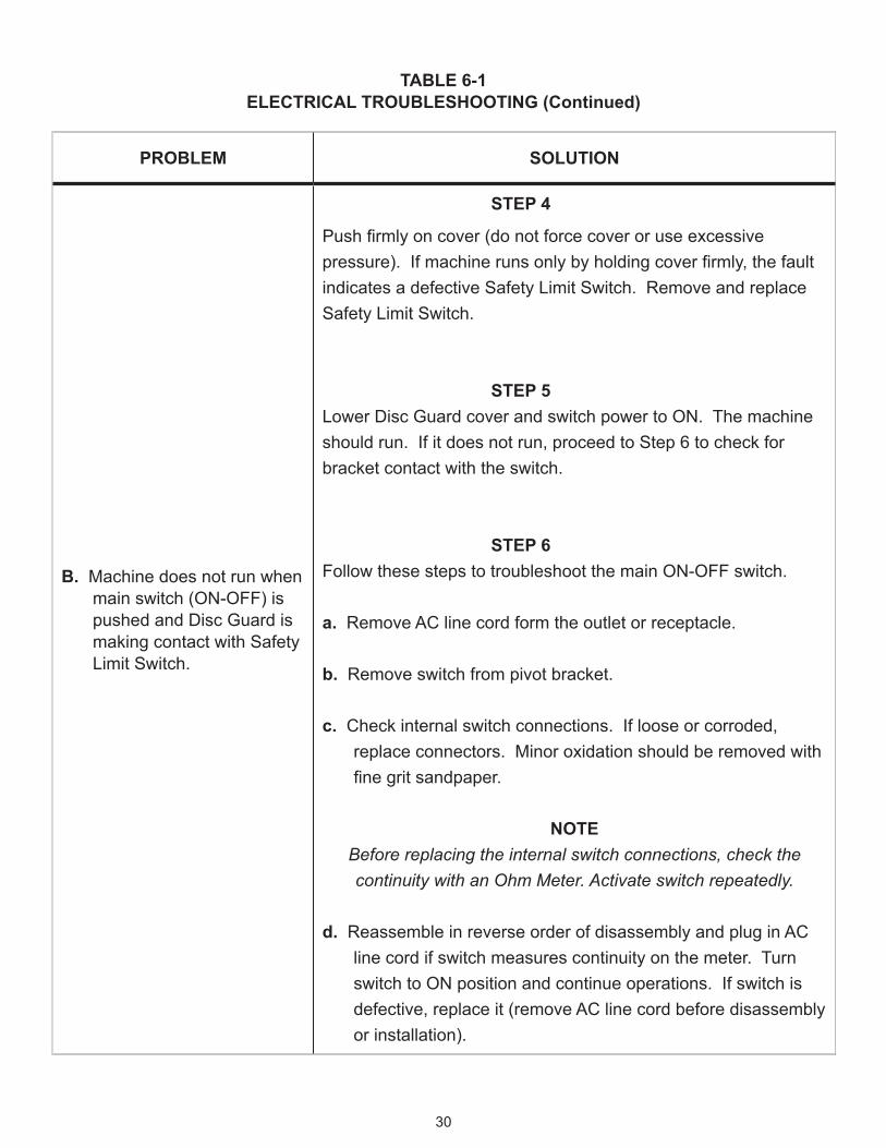
TABLE 6‑1ELECTRICAL TROUBLESHOOTING (Continued)
PROBLEM SOLUTION
B. Machine does not run when main switch (ON-OFF) is pushed and Disc Guard is making contact with Safety Limit Switch.
STEP 4
Pushfirmlyoncover(donotforcecoveroruseexcessivepressure).Ifmachinerunsonlybyholdingcoverfirmly,thefaultindicates a defective Safety Limit Switch. Remove and replace Safety Limit Switch.
STEP 5Lower Disc Guard cover and switch power to ON. The machine should run. If it does not run, proceed to Step 6 to check for bracket contact with the switch.
STEP 6Follow these steps to troubleshoot the main ON-OFF switch.
a. Remove AC line cord form the outlet or receptacle.
b. Remove switch from pivot bracket.
c. Check internal switch connections. If loose or corroded, replace connectors. Minor oxidation should be removed with finegritsandpaper.
NOTEBefore replacing the internal switch connections, check the continuity with an Ohm Meter. Activate switch repeatedly.
d. Reassemble in reverse order of disassembly and plug in AC line cord if switch measures continuity on the meter. Turn switch to ON position and continue operations. If switch is defective, replace it (remove AC line cord before disassembly or installation).
30

TABLE 6‑1ELECTRICAL TROUBLESHOOTING (Continued)
PROBLEM SOLUTION
B. Machine does not run when main switch is placed in the ON position and Disc Guard is making contact with Safety Limit Switch.
STEP 6 (CONTINUED)
If the machine still doesn't run, proceed to Step 7 to troubleshoot the Gearmotor.
STEP 7a. Inspect Gearmotor for "burnout". Usually an acrid odor
indicates a burned out commentator, sticking brushes, contacts, or faulty wiring.
b. Open junction box (Step 2) and inspect the motor wiring connections and the machine fuse. If faulty, replace fuse (may have "blown" while testing). If motor wires from motor to the junction box are defective, replace the wires.
NOTEInsert silicone sealer into all junction box screw holes before reassembly. Check gasket-if torn or loose, replace gasket.
c. Replace junction box cover, gasket, and screws.
NOTEMotor removal applies to new machines. See addendum 7.4 for
instructions on machines made prior to 2010.
d. Start machine-if it runs, continue operations. If machine does not run, replace motor by following these instructions:
· Remove 4 retaining bolts.
· Remove motor control wires.
· Remove motor and replace with new one in reverse order of disassembly. (Continued on next page.)
31

TABLE 6‑1ELECTRICAL TROUBLESHOOTING (Continued)
PROBLEM SOLUTION
B. Machine does not run when main switch is placed in the ON position and Disc Guard is making contact with Safety Limit Switch.
C. Machine continues to run when switched off.
STEP 7 (CONTINUED)
·Replace AC line cord to power the Linker.
·Start machine. If it runs, continue operations.
If machine does not run, repeat Step 2. If machine is
still inoperative, contact your local Nitta Casings Sales
Representative for assistance.
a. Pull AC line cord out of receptacle or outlet. Replace as
necessary. Observe all cautions.
b. Repeat previous procedures starting with switches and
control box wiring checkout. Do not attempt to bypass
electrical interlocks. If problem cannot be solved,
consult your local Nitta Casings Sales Representative for
assistance.
32
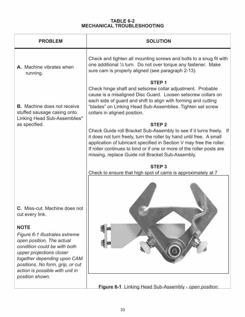
TABLE 6‑2MECHANICAL TROUBLESHOOTING
PROBLEM SOLUTION
A. Machine vibrates when running.
B. Machine does not receive stuffed sausage casing onto Linking Head Sub-Assemblies* asspecified.
C. Miss-cut. Machine does not cut every link.
NOTEFigure 6-1 illustrates extreme open position. The actual condition could be with both upper projections closer together depending upon CAM positions. No form, grip, or cut action is possible with unit in position shown.
Checkandtightenallmountingscrewsandboltstoasnugfitwithone additional ¼ turn. Do not over torque any fastener. Make sure cam is properly aligned (see paragraph 2-13).
STEP 1Check hinge shaft and setscrew collar adjustment. Probable cause is a misaligned Disc Guard. Loosen setscrew collars on each side of guard and shift to align with forming and cutting “blades” on Linking Head Sub-Assemblies. Tighten set screw collars in aligned position.
STEP 2Check Guide roll Bracket Sub-Assembly to see if it turns freely. If it does not turn freely, turn the roller by hand until free. A small applicationoflubricantspecifiedinSectionVmayfreetheroller.If roller continues to bind or if one or more of the roller posts are missing, replace Guide roll Bracket Sub-Assembly.
STEP 3Check to ensure that high spot of cams is approximately at 7 o’clock.
Figure 6‑1 Linking Head Sub-Assembly - open position.
33
TABLE 6‑2MECHANICAL TROUBLESHOOTING (Continued)
PROBLEM SOLUTION
C. Miss-Cut. Machine does not cut every link.
D. Miss-cut (double link). Machine does not cut every link. Links are continuous to about 8 inches in length or double the required 4-inch size. Linker Torsion Springs do not compress.
NOTEA number identifies each Linking Head Sub-Assembly location
on the Disc Assembly on the outer rim of the disc. Use the numbered positions to identify individual units.
a. Look through guard while machine is operating to observe which Linker is causing the cutting issue.
NOTEThe machine may be started & stopped quickly each time via the control box switch to determine which numbered Linker is
causing a Miss-Cut.
b. De-energize the machine and lift Disc Guard. Check faulty Linking Head Sub-Assembly by observing if blades and cutters overlap approximately 3/16”. Rotate the disc by hand until the numbered faulty Linker is at the top of the machine.
c.LoweridentifiedStopArmbyapproximately0.010inches.Carefully note and mark last position before loosening Stop Arm retaining screws. Secure Stop Arm in new position.
d. Secure Linker in new (lowered) position. Repeat Steps b and c until the 3/16” overlap is achieved. If overlap does not occur, check compression spring retaining nut (Figure 6-2). Tighten if loose and rotate disc by hand. Check to determine if 3/16” overlap occurs. If it does, continue operations. If not, remove faulty Linking Head and replace with new Linking Head Sub-Assembly.
NOTEObserve safety precautions (Paragraph 6.4) before continuing
with the next procedure.
34

TABLE 6‑2MECHANICAL TROUBLESHOOTING (Continued)
PROBLEM SOLUTION
D. Miss-cut (double link). Machine does not cut every link. Links are continuous to about 8 inches in length or double the required 4“ size. Linker Torsion Springs do not compress.
E. Shoulder break occurs as shown in Figure 6-3. Casing is broken.
a. Examine Linker Torsion Springs, Isolate faulty spring.
b. Remove any obstructions that would cause the Torsion Spring to keep blades in an open position.
c. Stop Machine. Remove and replace any faulty Torsion Spring. Refer to Section V for guidance.
Figure 6‑2 Miss-cut or 8” link.
Figure 6‑3 Link shoulder break.
a. Check for obstruction in Linking Head Sub-Assembly cutter insert (See Figure 6-1).
b. Check Z-Bar position in relation to insert cutting edge.
c. Check vertical distance of feed roller from feed table. It should not exceed 12”. See Figure 3-1 and Figure 3-2.
d.Checkforoverstuffing.
e. Check for incorrect wet-out conditions.
f. Check blade sets (Part # 05x02) for misalignment, looseness or deformity replace entire assembly.
35

TABLE 6‑2MECHANICAL TROUBLESHOOTING (Continued)
PROBLEM SOLUTION
F. Machine develops unusual noises.
STEP 1
a.Lubricateallfittings.
b. Isolate noise and service components.
c. Feel machine parts. If running hot, stop machine and repair or replace bearings, gearmotor, or parts.
STEP 2
a. Move machine to another location. Then re-start it and note any changes.
b. Remove and replace (or repair) faulty parts.
36
PARTS LISTSECTION VII
7.1 ORDERING PARTS
Use illustrations to identify the part and then refer to the NITTA “Z” Linker Model III Parts List for ordering information. When ordering parts, please include the part number, quantity, and part description.
7.2 PARTS NOT ILLUSTRATED
Certain parts may not be illustrated such as junction box wires, fasteners, washers, and other items. Refer to the original machine part and describe it by location and function.
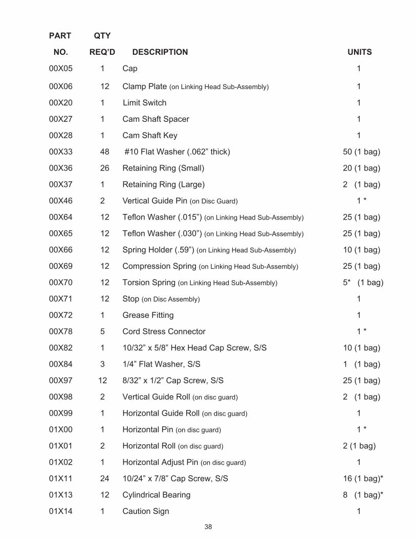
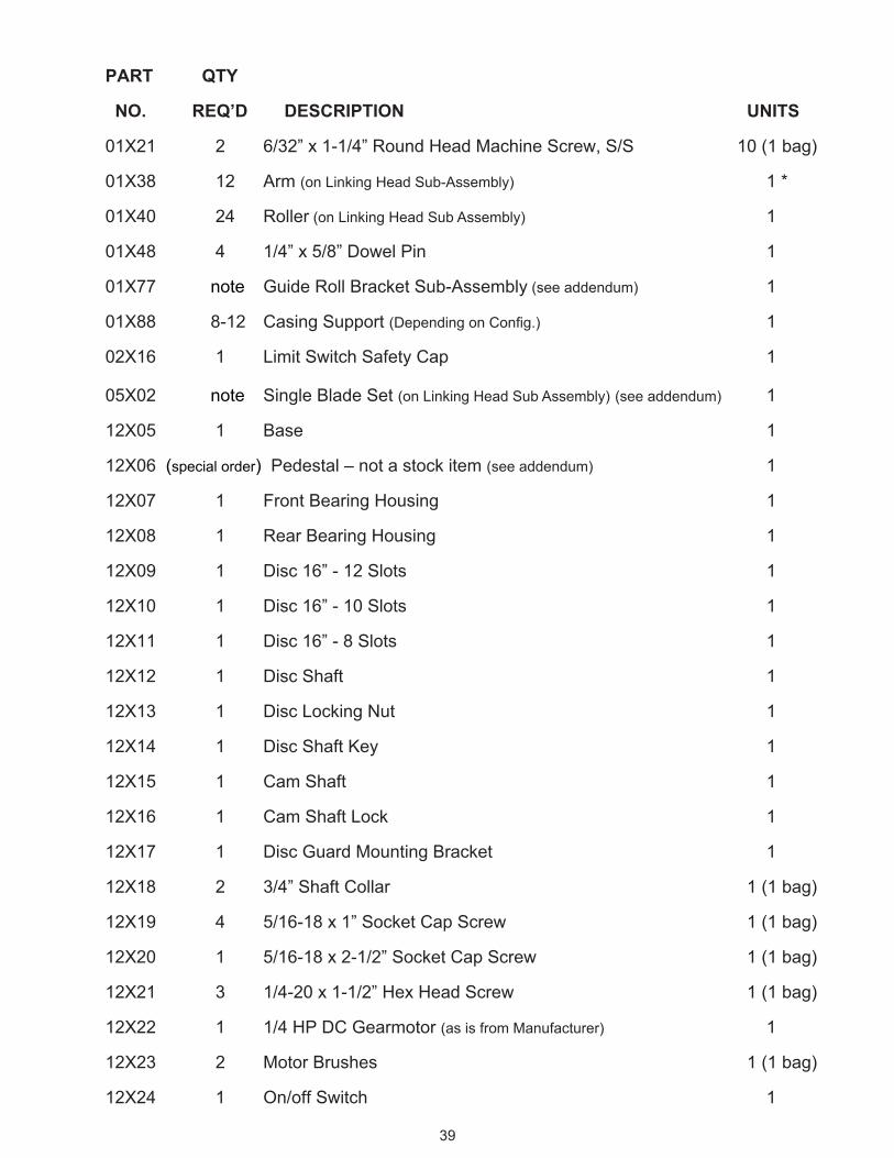
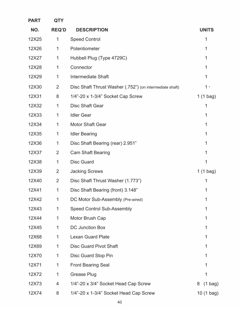
7.3 PARTS LIST
Attached is a list of parts for the NITTA “Z” Linker. If the word “note“ or “special“ is listed for your part number in the QUANTITY REQUIRED column, refer to the Addendum at the end of this section for more information.
37
PART QTY
NO. REQ’D DESCRIPTION UNITS
00X05 1 Cap 1
00X06 12 Clamp Plate (on Linking Head Sub-Assembly) 1
00X20 1 Limit Switch 1
00X27 1 Cam Shaft Spacer 1
00X28 1 Cam Shaft Key 1
00X33 48 #10 Flat Washer (.062” thick) 50 (1 bag)
00X36 26 Retaining Ring (Small) 20 (1 bag)
00X37 1 Retaining Ring (Large) 2 (1 bag)
00X46 2 Vertical Guide Pin (on Disc Guard) 1 *
00X64 12 TeflonWasher(.015”)(on Linking Head Sub-Assembly) 25 (1 bag)
00X65 12 TeflonWasher(.030”)(on Linking Head Sub-Assembly) 25 (1 bag)
00X66 12 Spring Holder (.59”) (on Linking Head Sub-Assembly) 10 (1 bag)
00X69 12 Compression Spring (on Linking Head Sub-Assembly) 25 (1 bag)
00X70 12 Torsion Spring (on Linking Head Sub-Assembly) 5* (1 bag)
00X71 12 Stop (on Disc Assembly) 1
00X72 1 Grease Fitting 1
00X78 5 Cord Stress Connector 1 *
00X82 1 10/32” x 5/8” Hex Head Cap Screw, S/S 10 (1 bag)
00X84 3 1/4” Flat Washer, S/S 1 (1 bag)
00X97 12 8/32” x 1/2” Cap Screw, S/S 25 (1 bag)
00X98 2 Vertical Guide Roll (on disc guard) 2 (1 bag)
00X99 1 Horizontal Guide Roll (on disc guard) 1
01X00 1 Horizontal Pin (on disc guard) 1 *
01X01 2 Horizontal Roll (on disc guard) 2 (1 bag)
01X02 1 Horizontal Adjust Pin (on disc guard) 1
01X11 24 10/24” x 7/8” Cap Screw, S/S 16 (1 bag)*
01X13 12 Cylindrical Bearing 8 (1 bag)*
01X14 1 Caution Sign 1
38
PART QTY
NO. REQ’D DESCRIPTION UNITS
01X21 2 6/32” x 1-1/4” Round Head Machine Screw, S/S 10 (1 bag)
01X38 12 Arm (on Linking Head Sub-Assembly) 1 *
01X40 24 Roller (on Linking Head Sub Assembly) 1
01X48 4 1/4” x 5/8” Dowel Pin 1
01X77 note Guide Roll Bracket Sub-Assembly (see addendum) 1
01X88 8-12 Casing Support (DependingonConfig.) 1
02X16 1 Limit Switch Safety Cap 1
05X02 note Single Blade Set (on Linking Head Sub Assembly) (see addendum) 1
12X05 1 Base 1
12X06 (special order) Pedestal – not a stock item (see addendum) 1
12X07 1 Front Bearing Housing 1
12X08 1 Rear Bearing Housing 1
12X09 1 Disc 16” - 12 Slots 1
12X10 1 Disc 16” - 10 Slots 1
12X11 1 Disc 16” - 8 Slots 1
12X12 1 Disc Shaft 1
12X13 1 Disc Locking Nut 1
12X14 1 Disc Shaft Key 1
12X15 1 Cam Shaft 1
12X16 1 Cam Shaft Lock 1
12X17 1 Disc Guard Mounting Bracket 1
12X18 2 3/4” Shaft Collar 1 (1 bag)
12X19 4 5/16-18 x 1” Socket Cap Screw 1 (1 bag)
12X20 1 5/16-18 x 2-1/2” Socket Cap Screw 1 (1 bag)
12X21 3 1/4-20 x 1-1/2” Hex Head Screw 1 (1 bag)
12X22 1 1/4 HP DC Gearmotor (as is from Manufacturer) 1
12X23 2 Motor Brushes 1 (1 bag)
12X24 1 On/off Switch 1
39
PART QTY
NO. REQ’D DESCRIPTION UNITS
12X25 1 Speed Control 1
12X26 1 Potentiometer 1
12X27 1 Hubbell Plug (Type 4729C) 1
12X28 1 Connector 1
12X29 1 Intermediate Shaft 1
12X30 2 Disc Shaft Thrust Washer (.752”) (on intermediate shaft) 1 *
12X31 8 1/4”-20 x 1-3/4” Socket Cap Screw 1 (1 bag)
12X32 1 Disc Shaft Gear 1
12X33 1 Idler Gear 1
12X34 1 Motor Shaft Gear 1
12X35 1 Idler Bearing 1
12X36 1 Disc Shaft Bearing (rear) 2.951” 1
12X37 2 Cam Shaft Bearing 1
12X38 1 Disc Guard 1
12X39 2 Jacking Screws 1 (1 bag)
12X40 2 Disc Shaft Thrust Washer (1.773”) 1
12X41 1 Disc Shaft Bearing (front) 3.148” 1
12X42 1 DC Motor Sub-Assembly (Pre-wired) 1
12X43 1 Speed Control Sub-Assembly 1
12X44 1 Motor Brush Cap 1
12X45 1 DC Junction Box 1
12X68 1 Lexan Guard Plate 1
12X69 1 Disc Guard Pivot Shaft 1
12X70 1 Disc Guard Stop Pin 1
12X71 1 Front Bearing Seal 1
12X72 1 Grease Plug 1
12X73 4 1/4”-20 x 3/4” Socket Head Cap Screw 8 (1 bag)
12X74 8 1/4”-20 x 1-3/4” Socket Head Cap Screw 10 (1 bag)
40

PART QTY
NO. REQ’D DESCRIPTION UNITS
12X75 2 1/4”-20 x 1-1/4” Socket Head Cap Screw 2 (1 bag)
12X76 4 1/4”-28 x 3/4” Socket Head Cap Screw 4 (1 bag)
12X77 1 Motor Mount Sub-Plate 1
12X78 2 1/4”-20 x 1-1/4” Flat Head Socket Cap Screw 2 (1 bag)
12X79 1 1/4”-20 x 3/16” Socket Set Screw 1
12X80 3 1/4”-20 x 1/4” Socket Set Screw 3 (1 bag)
12X81 1 1/4”-20 x 3/8” Socket Set Screw 4 (2 bags)
12X82 2 1/4”-20 x 1/2” Socket Set Screw 2 (1 bag)
12X83 1 1/4”-20 x 3/4” Socket Set Screw 1
12X84 1 Hubbell Seal Tite Cover HBL6023 1
12X85 1 Hubbell Seal Tite Cover HBL6024 1
86X29 1 Disc Shaft Gear Key 1
Left Hand Z‑Linker Machine Parts 12X61 1 Disc Guard Mounting Bracket - LH (in lieu of 12X17) 1
12X62 1 Disc 16” - 12 Slots - LH (in lieu of 12X09) 1
12X63 1 Disc 16” - 10 Slots - LH (in lieu of 12X10) 1
12X66 1 Disc 16” - 8 Slots - LH (in lieu of 12X11) 1
12X86 1 Base - LH (in lieu of 12X05) 1*
86X41 8 Arm (on Linking Head Sub Assembly) LH (in lieu of 01X38) 1 *
Note: “ * ” one should be sufficient. However, it would take more for total parts replacement.
41

CAMS
PART QTY
NO. REQ’D DESCRIPTION UNITS
12X59 Cam 3.437 1 pair (1 set)
12X50 Cam 3.5 1 pair (1 set)
12X67 Cam 3.5 (fast rise) 1 pair (1 set)
12X51 Cam 3.625 1 pair (1 set)
12X52 Cam 3.75 1 pair (1 set)
12X57 Cam 3.75 (fast rise) 1 pair (1 set)
12X53 Cam 3.875 1 pair (1 set)
12X58 Cam 3.875 (fast rise) 1 pair (1 set)
12X54 Cam 4.0 1 pair (1 set)
12X60 Cam 4.0 (fast rise) 1 pair (1 set)
12X56 Cam 4.25 1 pair (1 set)
Cams are sold in paired sets only.
42
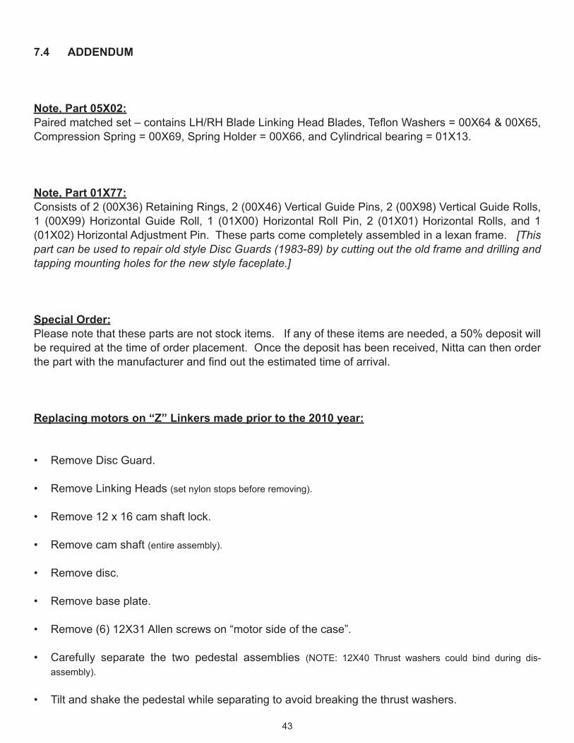
7.4 ADDENDUM
Note, Part 05X02:Pairedmatchedset–containsLH/RHBladeLinkingHeadBlades,TeflonWashers=00X64&00X65,CompressionSpring=00X69,SpringHolder=00X66,andCylindricalbearing=01X13.
Note, Part 01X77:Consists of 2 (00X36) Retaining Rings, 2 (00X46) Vertical Guide Pins, 2 (00X98) Vertical Guide Rolls, 1 (00X99) Horizontal Guide Roll, 1 (01X00) Horizontal Roll Pin, 2 (01X01) Horizontal Rolls, and 1 (01X02) Horizontal Adjustment Pin. These parts come completely assembled in a lexan frame. [This part can be used to repair old style Disc Guards (1983-89) by cutting out the old frame and drilling and tapping mounting holes for the new style faceplate.]
Special Order:Please note that these parts are not stock items. If any of these items are needed, a 50% deposit will be required at the time of order placement. Once the deposit has been received, Nitta can then order thepartwiththemanufacturerandfindouttheestimatedtimeofarrival.
Replacing motors on “Z” Linkers made prior to the 2010 year:
Remove Disc Guard.•
Remove Linking Heads • (set nylon stops before removing).
Remove 12 x 16 cam shaft lock.•
Remove cam shaft • (entire assembly).
Remove disc.•
Remove base plate.•
Remove (6) 12X31 Allen screws on “motor side of the case”.•
Carefully separate the two pedestal assemblies • (NOTE: 12X40 Thrust washers could bind during dis-assembly).
Tilt and shake the pedestal while separating to avoid breaking the thrust washers.•
43

Figu
re 7
-1 L
inki
ng H
ead
Sub
-Ass
embl
y
00X
36*
01X
13*
00X
64*
01X
11**
00X
33*
00X
06**
01X
38(8
6X41
) LE
FT H
AN
DN
ote:
01X
38/8
6X41
incl
udes
al
l **
parts
.
00X
66*
00X
69*
00X
70
00X
65*
05X
02N
ote:
05X
02 in
clud
es a
ll of
th
e *
parts
.
00X
33
01X
40*
00X
33**
00X
9744

Figu
re 7
-2 P
edes
tal A
ssem
bly
Sec
tion
A
00X
27
01X
88N
ote:
Thi
s pa
rt is
opt
iona
l an
d no
w c
omes
in th
e fo
rm
of a
pos
t in
lieu
of th
e pa
ddle
sh
own
here
.
00X
82
Ref
er to
CA
M L
ist.
00X
37
12X
13
00X
05
12X
09,1
0,O
R 1
112
X15
00X
71
00X
28
45

Figu
re 7
-3 P
edes
tal A
ssem
bly
Sec
tion
B
12X
37
(2) 1
2X75
12X
06
01X
48
12X
07
12X
71
86X
29
12X
12
12X
14
12X
37
12X
41
46
(2) 1
2X73
Figu
re 7
-4 P
edes
tal A
ssem
bly
Sec
tion
C
12X
06
12X
8212
X81
12X
7212
X06
12X
31
(4) 1
2X74
12X
73
(4) 0
1X48
Com
es w
/ the
M
otor
.
12X
34
12X
35
12X
29
00X
72
12X
33
12X
30
12X
7912
X32
12X
40
12X
80
(2) 1
2X73
(6) 1
2X31
47
(2) 1
2X75
Figu
re 7
-5 P
edes
tal A
ssem
bly
Sec
tion
D
12X
31
12X
36
Key
com
es w
/ M
otor
.
(6) 1
2X31
12X
42O
ptio
n D
C M
otor
Sub
A
ssem
bly.
(Pre
-wire
d)
12X
08
12X
22M
otor
as
is fr
om
man
ufac
ture
r.
(4) 0
1X48
12X
20
(4) 1
2X74
12X
78
12X
73
12X
1612
X83
12X
06
48
Figu
re 7
-6 P
edes
tal A
ssem
bly
Sec
tion
E
12X
06Av
aila
ble
on a
ll ne
w m
odel
s.O
lder
Mod
els
can
call
for R
ear
Ped
esta
l & M
otor
Mou
nt U
pgra
de.
(4) 1
2X73
12X
77(4
) 12X
76
(2) 0
1X48
49