Model LF-210 Air Operated · 2018-03-16 · Model LF-210 Air Operated Installation/Service Manual...
16
452 East Hill Road Fax: 707.459.6617 Willits, CA 95490 USA E-mail: [email protected] Phone: 707.459.5563 www.microphor.com 10/16/01 Toll Free: 1.800.358.8280 www.wabtec.com 24154.WPD Microflush Half Gallon Toilets Model LF-210 Air Operated Installation/Service Manual P/N 24154
Transcript of Model LF-210 Air Operated · 2018-03-16 · Model LF-210 Air Operated Installation/Service Manual...

452 East Hill Road Fax: 707.459.6617 Willits, CA 95490 USA E-mail: [email protected] Phone: 707.459.5563 www.microphor.com 10/16/01 Toll Free: 1.800.358.8280 www.wabtec.com 24154.WPD
Microflush Half Gallon Toilets
Model LF-210Air Operated
Installation/Service Manual P/N 24154

LF-210 Manual P/N 24154 2 April, 2003
ROUGH-IN DIMENSIONSCut out at rear of toilet. Run 1/4" compressed airline through finished wall or floor within inside perimeter oftoilet. NOTE: Toilet is designed for flush installation to finished wall. Below are rough-in dimensions and mayvary ½" (plus or minus). These measurements are subject to change or modification. No responsibility isassumed for use of superseded or voided installation information.

LF-210 Manual P/N 24154 3 April, 2003
How Microflush Toilets Operate
THANK YOU!Thank you for purchasing a Microphor product. Please read this manual completely prior toinstallation of your Microflush® toilet. MicrophorGeneral Terms and Conditions Covering Salesapply.
CUSTOMER SERVICEIf you have any questions concerning yourMicrophor product, please contact us:
8:AM-5:PM PST Monday-FridayTel: (800) 358-8280 or (707) 459-5563Fax: (707) 459-6617, 24 hourE-mail: [email protected]: www.microphor.com
PATENTSMicroflush toilets are covered by one or more ofthe following U.S. patents 5245710; 4918764;1280554; 169471 and related foreign patents.
CHANGES IN DESIGNContinuing a policy of research and development,Microphor reserves the right of price, product ordesign change without notice or obligation.
APPLICATIONSLand: Read this manual.Railroad: See additional Railroad Installation
Instructions & Specifications
CAUTIONSWater Pressure to the toilet must be regulated atan even pressure between 20 to 50 PSI.Air Pressure at the toilet must be regulated at 60-65PSI constant.
Do Not Use any "Loctite" brand adhesive on anyplastic components as fumes willcause damage to plastic parts.
Do Not Use products containing petroleumdistillates or formaldehyde on anyrubber parts. Use only Silicone lubricants.
Do Not Use Teflon tape on any air fittings asclogging may occur.
System vacuum breaker is not intended to bepressurized longer than a normal flushing cycle.

LF-210 Manual P/N 24154 4 April, 2003
AIR SYSTEM DESIGNFilter-regulators areavailable in a variety ofsizes and types. Theirpurpose is to removewater, oil and otherforeign matter from the airline and to maintain aconstant pressure of 60-65PSI at the toilet. Thefollowing steps must beobserved to assure moisture will be removed fromthe airline:1. Drain air compressor receiver regularly. Most
water tends to accumulate at this point.2. Install drip legs with condensate drains at all
low points in air piping.3. Whenever possible, grade all airlines back to air
receiver or drip leg assembly and drainregularly.
4. The air supply to the toilet must be taken fromthe top of the main or branch air line.
AIR COMPRESSORBe certain compressor crankcase has proper oillevels. Locate the compressor in a clean, dry, wellventilated location. Size compressor according toAir Compressor Spec, Form 273.
INSTALLATION PROCEDURERead InstallationProcedures completelyregarding allinstallation/start up pointsprior to installation.
PRELIMINARY PROCEDURERemove toilet from box carefully. Install toilet seatand flush handle before mounting toilet to floor. Seat is not included with vitreous china models. Airconnecting kit (P/N 93086), bolt caps and closetscrews are provided with all vitreous china models.
AIR CONNECTIONInstall a filter-regulatorassembly in airline. Placethe filter-regulator as closeas possible to the firsttoilet and in an accessiblelocation. The plasticairline (provided) from theair source connects to the toilet at the flushactivator. On models where the flush handle ismounted on the side of the toilet, the plastic air lineenters the toilet through the back wall or up throughthe floor under the back of the toilet. Install airshut-off valve at toilet. Fitting on toilet is 1/4"compression fitting. Do not over-tighten fittings ontoilet. Blow any debris from airline prior toconnecting to toilet.Regulate air pressure to 60-65 PSI constant atthe toilet for proper operation.
Where an air main is required, such as a 1/2" copperline, the air line to the toilet should be connected tothe top of the main airline to prevent condensationreaching the toilet.
WATER CONNECTIONInstall water shut-off valve (anglestop) at 9" off center line and 3"above floor (see Rough-InDimensions). Water supply lineshould be 1/2" flexible line. Fittingon toilet is ½" NPT slip joint nut(1/2" lavatory supply). Connectflexible water supply line to toiletfirst, then connect to angle stop.CAUTION: Water supply connector is made of
nylon. Be careful not to crossthreads.
Water pressure must be regulated at an evenpressure between 20 to 50 PSI at the toilet for itto operate properly.

LF-210 Manual P/N 24154 5 April, 2003
DRAIN CONNECTION - See Rough-In DimensionsBottom Discharge Models: Center on floor flange12" (standard) from finished wall with wax ring(provided). If floor is uneven a second standard waxring may be added. If bottom ring of toilet hitsflange, it should be ground down for addedclearance, as any contact will break seal on hopper.
Rest toilet on its back on a padded surface (e.g.packing from shipping box). Center wax ring ontoilet discharge flange. Turn toilet over, lifting up,and center the horn of the wax ring into the toiletfloor flange. Compress the wax ring by applyingweight to the toilet.
REAR DISCHARGE MODELS: Discharge lineshould be connections at hopper with a No-HubCoupling (P/N 33324, provided). Do not glue orconnect fittings until fitting alignment has beenchecked. Toilet discharge line must have a rise(trap) (see ROUGH-IN DIMENSIONS) in order toprovided water trap seal when flapper is open. CAUTION: do not apply stress to align outlet towaste line. This will result in eventual seal damage.
DOWNWARD DISCHARGE MODELS: Toiletmounts to floor with 1/4" closet bolts. Install screwswith a 3/8" nut driver. Screw on bolt caps tomounting screws.
INSTALLATION AND START UP1. Position and mount
the Toilet to floor. See Rough-InDimensions.
2. For units withRemote Flush,position and mountRemote FlushAssembly to wall with Vacuum Breaker at least6" above the rim of the toilet bowl. Themaximum water line distance between the toiletand the Remote Flush Assembly is 4'.
3. Position and mount the Flush Activator to wall.The maximum distance between the FlushActivator and the Remote Flush Assembly is72".
4. Connect the incoming water supply to the 3/4"I.D. Hose Barb on the Remote Flush Assembly.
5. Connect the water line from Remote FlushAssembly to the toilet spud assembly.
6. Assemble the Air Connecting Kit (P/N 93086)provided and connect to incoming air supply. Do not connect to flush Activator.
7. Turn OFF air shut-off cock at toilet.8. Turn ON air supply at compressor.9. Turn ON air shut-off cock at toilet to blow out
airlines for a few seconds. This procedureshould remove any debris or contaminants fromthe airline. Turn OFF air shut-off cock.
10. Now connect airline to the top of the FlushActivator. Turn ON air shut-off cock. Checktotal installation for air leaks using soapy water.
11. Turn ON water. Check for water leaks.12. Flush toilet four times, waiting twenty seconds
between flushes to get water through toilet andoperating regularly. To flush properly, holddown handle until flapper opens.
13. Water level in bowl should be at top edge offlapper opening.
14. If the toilet does not operate correctly or havethe proper water level in bowl, refer to adjustingToilet or Troubleshooting sections of thismanual.

LF-210 Manual P/N 24154 6 April, 2003
USAGE LUBRICATELight Every 5 yearsMedium Every 2-3 yearsHeavy Every year
ROUTINE MAINTENANCEYour Microflush toilethas an air-operatedAir/Water SequenceValve which requiresperiodic lubricationwith a silicone basedlubricant.
CLEANINGUse Micro-Clean Organic Spray Cleaner, P/N24542. Caustic drain openers or non-biodegradablecleaners should not be used if the toilet is connectedto a septic tank or Microphor biological sewagetreatment system. Clean as follows:1. While depressing the flush activator, turn OFF
the water. Allow the bowl cleaner to flow intothe lower chamber. Keep the flushing activatordepressed.
2. Insert bowl brush into lower chamber and agitatemixture.
3. Remove the bowl brush and release the flushactivator.
4. Turn the water ON and flush twice to rinsethoroughly.
WINTERIZING (out-of-service winter storage)Shut OFF water to toilet. Flush toilet three times oruntil water no longer flows into the bowl. Unhookwater supply at angle stop. Empty water in line intoreceptacle. Shut OFF air supply to the toilet. Theunit is now prepared for freezing temperatures. OPEN petcocks on drip legs and air receiver drainafter shutting down air compressor and isolatingairlines.
Pipe will protect flapper seal. If valve will notoperate with water off, hold flush lever down andturn water on and off quickly to free valve action. When the passage becomes clear, turn on the waterand press flush handle to start the flush cycle.
CLEANING BLEED-OFF PLUGASSEMBLYStandard Flush:Remove plug and clean with solvent; air blow dry.Positive Flush:Remove plug and clean with solvent; air blow dry;remove and clean plug on Detent Valve.
Note: Use 5/32" or 4mm Allen wrench to removeplugs.
CLEARING THE TOILETIf the toilet becomes plugged, shut off the watersupply, press the flush handle and hold. Flapper inthe bottom of the toilet will remain open until flushhandle is released. Check to see if the restrictioncan be removed from lower portion of toilet with ahooked wire, being careful not to damage the rubberseal on the flapper or the mating surface on thehopper. If obstruction can not be picked out with ahook or tongs, use plunger by pushing in slowly andpulling out quickly to pull object back into thehopper. If necessary, turn air off and use a snakeinserted into a short plastic pipe placed in hopper.
Note: Bleed-off plugs on Air & Water SequenceValves and Detent Valves are different sizes that arenot interchangeable.
LF-210 Manual P/N 24154 7 April, 2003
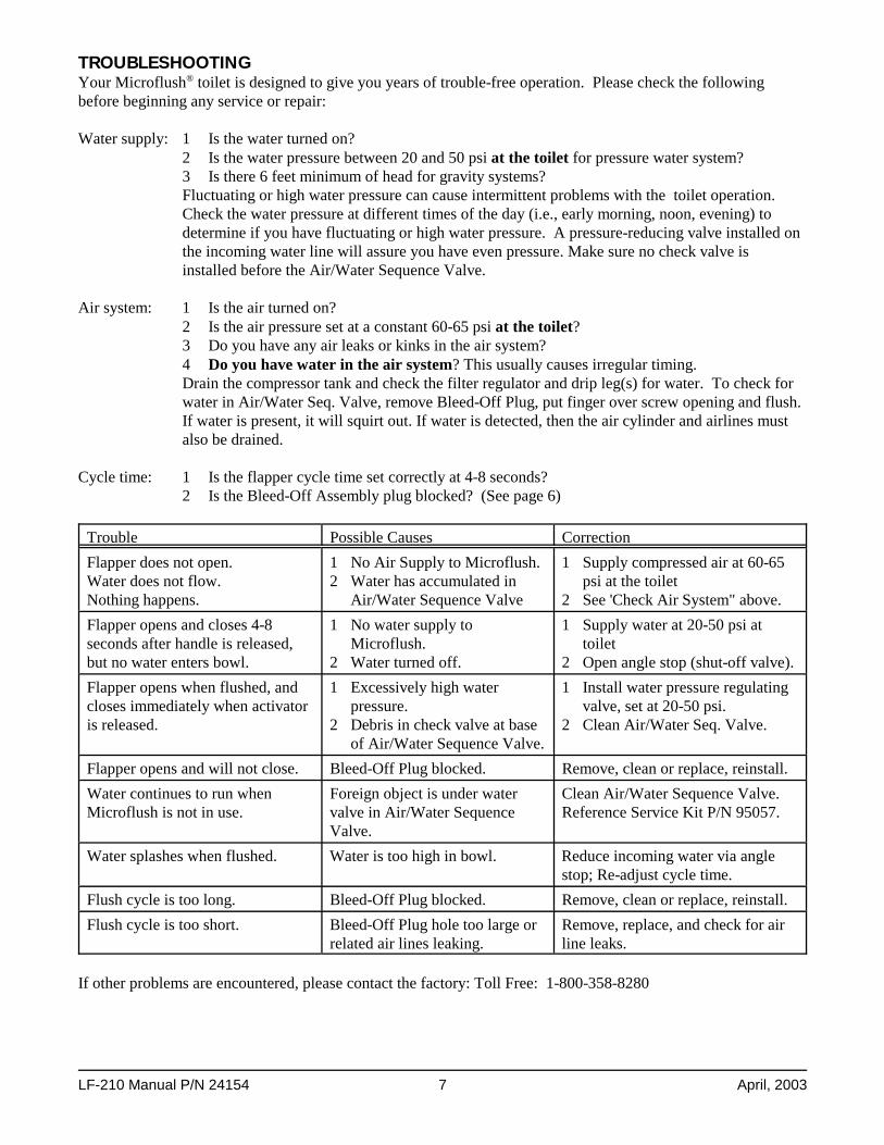
TROUBLESHOOTING Your Microflush® toilet is designed to give you years of trouble-free operation. Please check the followingbefore beginning any service or repair:
Water supply: 1 Is the water turned on?2 Is the water pressure between 20 and 50 psi at the toilet for pressure water system?3 Is there 6 feet minimum of head for gravity systems?Fluctuating or high water pressure can cause intermittent problems with the toilet operation. Check the water pressure at different times of the day (i.e., early morning, noon, evening) todetermine if you have fluctuating or high water pressure. A pressure-reducing valve installed onthe incoming water line will assure you have even pressure. Make sure no check valve isinstalled before the Air/Water Sequence Valve.
Air system: 1 Is the air turned on?2 Is the air pressure set at a constant 60-65 psi at the toilet?3 Do you have any air leaks or kinks in the air system?4 Do you have water in the air system? This usually causes irregular timing.Drain the compressor tank and check the filter regulator and drip leg(s) for water. To check forwater in Air/Water Seq. Valve, remove Bleed-Off Plug, put finger over screw opening and flush. If water is present, it will squirt out. If water is detected, then the air cylinder and airlines mustalso be drained.
Cycle time: 1 Is the flapper cycle time set correctly at 4-8 seconds?2 Is the Bleed-Off Assembly plug blocked? (See page 6)
Trouble Possible Causes CorrectionFlapper does not open.Water does not flow.Nothing happens.
1 No Air Supply to Microflush.2 Water has accumulated in
Air/Water Sequence Valve
1 Supply compressed air at 60-65psi at the toilet
2 See 'Check Air System" above.Flapper opens and closes 4-8seconds after handle is released,but no water enters bowl.
1 No water supply toMicroflush.
2 Water turned off.
1 Supply water at 20-50 psi attoilet
2 Open angle stop (shut-off valve).Flapper opens when flushed, andcloses immediately when activatoris released.
1 Excessively high waterpressure.
2 Debris in check valve at baseof Air/Water Sequence Valve.
1 Install water pressure regulatingvalve, set at 20-50 psi.
2 Clean Air/Water Seq. Valve.
Flapper opens and will not close. Bleed-Off Plug blocked. Remove, clean or replace, reinstall.Water continues to run whenMicroflush is not in use.
Foreign object is under watervalve in Air/Water SequenceValve.
Clean Air/Water Sequence Valve. Reference Service Kit P/N 95057.
Water splashes when flushed. Water is too high in bowl. Reduce incoming water via anglestop; Re-adjust cycle time.
Flush cycle is too long. Bleed-Off Plug blocked. Remove, clean or replace, reinstall.Flush cycle is too short. Bleed-Off Plug hole too large or
related air lines leaking.Remove, replace, and check for airline leaks.
If other problems are encountered, please contact the factory: Toll Free: 1-800-358-8280

LF-210 Manual P/N 24154 8 April, 2003
VITREOUS CHINA COLOR CHARTA B C
ChinaColor Code
RoundShell &
Lid
Elong.Shell &
LidLid
OnlyBoltCaps
Beige SC4 44333 44334 99064-15 44371Black N-5 44337 44338 99064-7 44076Blue B-5 44343 44344 99064-13 44373Bone S4 44039 44012 99064-3 93974Gray 651 44329 44330 99064-5 44377Ivory SC1 44327 44328 99064-24 44370Oak N/A N/A N/A 99071 N/APink SR2 44331 44332 99064-21 44368Red R-5 44345 44346 99064-9 44372Rose R3 44335 44336 99064-17 44375White -- 44023 44010 99064 93972
Integral Valve Layout
Remote Installation
EXPLODED VIEWS

LF-210 Manual P/N 24154 9 April, 2003
Air Lines from Air/Water Seq. Valve
Air Line LayoutsPARTS CHART
PART Integral RemoteD Flush
Activatorstandard 95002 N/Apositive 95054 95086
Pilot Valve standard 95562 N/Apositive 95083 95085
E Air/Water Sequence Valve 39501Rebuilt 39501 Exchange 99899
F Vacuum Breaker 33559 33039Vacuum Breaker Mntg Bracket 91897 20003
G Bleed-OffPlug Assy.
standard 94598remote 95100
H Valve Mounting Bracket 91897 20003I Hopper Rear Discharge 90005-3
Downward Disch. 90004-3 Down Conv. Kit 90008 P-Trap 96029Crank Assy 90042Flapper Assy 90048Screws (14 each) 00064Top 90003Bottom, Down 90002Bottom, Rear 90009Flange 45010
K Mounting Assy 90899-5N Air Cylinder 94540Q Spud Assy 96347 96004R Water Supply Tube 96352 35053S Water Connection 96387T Air Fittings
1/4" O.D. 90E 30385180E 30365Nut/Ferrell 30396
U Air Tubingper foot
green-35381, blue-35382, red-35383,yellow-35384, white-35385, black-35419
V Air Shut-Off Cock 30008W Air Connecting Kit 93086KITS
Master Service Kit 93100Air/Water Seq. Valve Kit 95057Air Cylinder Kit 94502Flush Activator (Standard) Kit 95020Flush Activator (Positive) Kit 95081Flapper Kit 90066Vacuum Breaker Kit 95037

LF-210 Manual P/N 24154 10 April, 2003
Rear Discharge Hopper
Downward Discharge Hopper
HOPPER REPLACEMENT
CAUTION: Read this Entire Procedure Before Beginning Work!
1. Remove toilet from floor. Place toilet upside down on a sheet of cardboard or other padded surface.2. Remove nuts from J-bolts on either side of Hopper, lift hopper away from bowl.3. Remove O-ring from between hopper and sealing adaptor. Check that O-ring is not damaged.4. Re-assemble in reverse order. MAKE SURE J-BOLTS ARE TIGHT! Proper torque specification is 4-6
inch/lbs.
HOPPER COMPONENTS
J - Optional P-trap, P/N 96029
To Change Flapper Gasket: 1. Turn water and air off.2. Reach behind flapper to grasp gasket tails.3. Pull tails out of slots to remove old gasket.4. Installation is the reverse of removal.5. Tails must be pulled all the way through to insure smooth surface.
LF-210 Manual P/N 24154 11 April, 2003
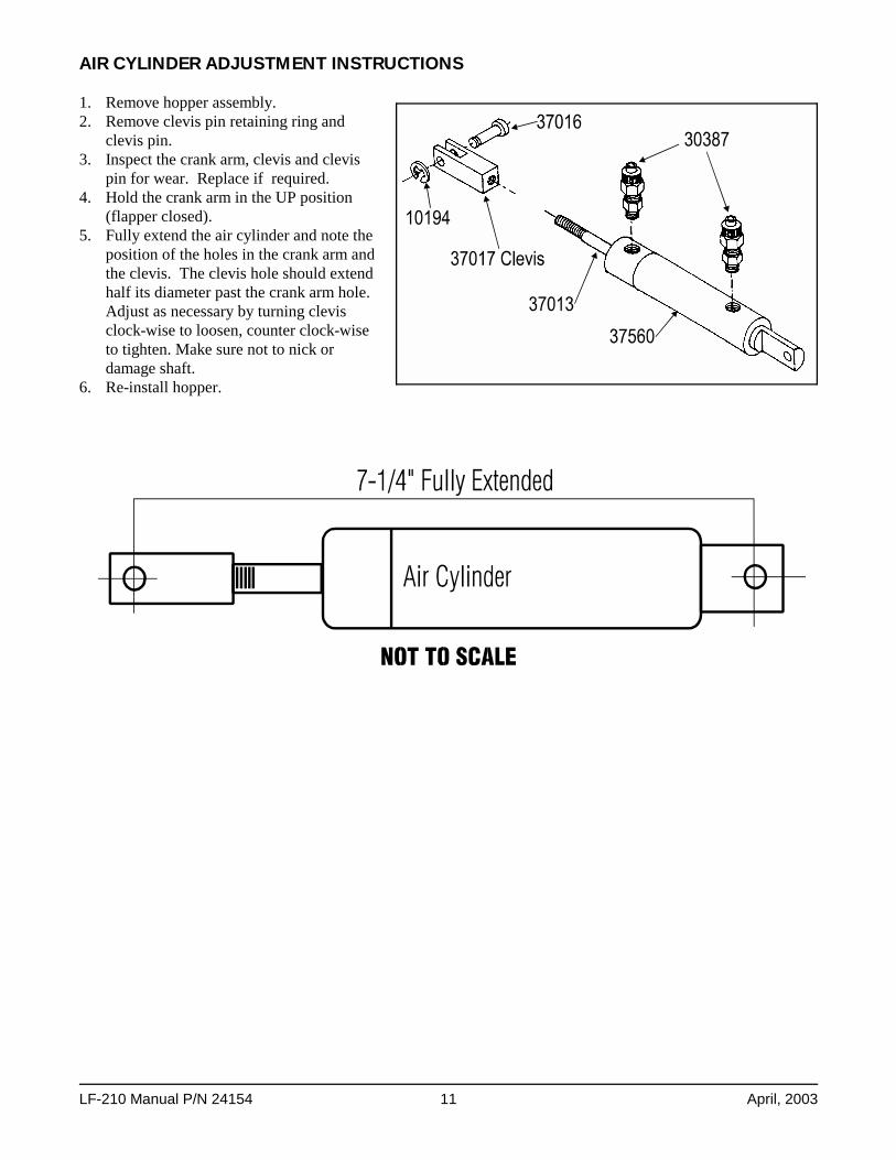
AIR CYLINDER ADJUSTMENT INSTRUCTIONS
1. Remove hopper assembly.2. Remove clevis pin retaining ring and
clevis pin.3. Inspect the crank arm, clevis and clevis
pin for wear. Replace if required.4. Hold the crank arm in the UP position
(flapper closed).5. Fully extend the air cylinder and note the
position of the holes in the crank arm andthe clevis. The clevis hole should extendhalf its diameter past the crank arm hole.Adjust as necessary by turning clevisclock-wise to loosen, counter clock-wiseto tighten. Make sure not to nick ordamage shaft.
6. Re-install hopper.

LF-210 Manual P/N 24154 12 April, 2003
FLUSH ACTIVATORS
95054 - Commercial Flush Activator95557 - Palm Button Conversion Kit
95002 - Residential Flush Activator

LF-210 Manual P/N 24154 13 April, 2003
POSITIVE FLUSH ACTIVATOR (Commercial) Remote, P/N 95087The Detented Positive Flush Activator has been added (as an option) to our product line. It was developed inorder to overcome the necessity for the toilet user to hold the standard flush actuator in the deflected position fora definite time (about 2 1/2 seconds) to insure full actuation of the toilet flush cycle. This option isrecommended for high use, public facilities.
It's principle of operation is as follows:A) Under user control, a two way valve, requiring no more than 1/32" deflection for full flow, pilots a piston
drive detented mechanism.B) The detent force is overcome after air pressure over the piston rises to 40 psi thus driving the standard flush
actuator to the full flush position.C) The detent is reset after the entrapped air over the piston is bled to atmosphere. The bleed rate (and thus the
length of time the flush actuator is held in the flush mode) is controlled by the head bleed plug with a fixedorifice size.

LF-210 Manual P/N 24154 14 April, 2003
AIR WATER SEQUENCE VALVE LUBRICATION1. Disassemble valve from bottom to top by first unscrewing the Bottom Cap from the Main Body. Then, to
unthread the piston from the spool, insert a 3/16" hex into the hex opening at top of spool. Use an adjustableend wrench on the oblong boss on bottom of piston to unscrew piston from spool and push spool up throughvalve body to remove. Remove Top Cap and Water Seal. You will need a pair of needle nose pliers toremove the Nut and Stem from the Bottom Cap.
2. Replace parts indicated in BOLD supplied with kit. Lubricate all O-Rings with lubricant provided. A light,complete coating is all that is required as over lubrication will clog air passages.
3. Re-assemble valve from top to bottom as shown, with the exception of the Top Cap and Water Seal which goon last. Make sure to align the yellow timing marks on Bottom Cap, Main Body and Water Body.
4. If desired, this valve may be returned to the factory for rebuilding and lubrication.

LF-210 Manual P/N 24154 15 April, 2003
AIR/WATER SEQUENCE VALVE OPERATION

LF-210 Manual P/N 24154 16 April, 2003
Insert Terms & Conditions.