
MODEL IPIC SERIES 4G GREASE DUCT - Metal-Fab …. GENERAL INFORMATION. LISTINGS: Metal-Fab IPIC...
12
INSTALLATION AND MAINTENANCE INSTRUCTIONS WALMART APPLICATION MODEL IPIC SERIES 4G GREASE DUCT IT IS OF THE UTMOST IMPORTANCE THAT THIS DUCT BE INSTALLED ONLY IN ACCORDANCE WITH THESE INSTRUCTIONS. IMPORTANT: DO NOT INSTALL GREASE DUCT WITHOUT FIRST READING THESE INSTRUCTIONS VERY CAREFULLY. COMBUSTIBLE MATERIAL: Material made of or surfaced with wood, compressed paper, plant fibers, plastic or other material that will ignite and burn, whether flame proofed or not, or whether plastered or unplastered. Metal-Fab’s series 4G Grease Duct System has been fully tested, listed and classified by Underwriters Laboratories, Inc. and Underwriters Laboratories of Canada. Metal-Fab’s Series 4G Grease Duct Systems have been evaluated and accepted by BOCA, SBCCI, and ICBO as an alternative to a two hour fire rated shaft enclosure when installed in accordance with these installation instructions. Grease Duct installed in accordance with these Installation Instructions meet the requirements of NFPA96. These instructions contain complete information on details concerning dimensions, installation, clearance to combustibles, use of noncombustible enclosures, and Firestops. For any additional information, refer to the parts catalog. METAL-FAB INC., • P.O. BOX 1138, WICHITA, KANSAS 67201 • (316) 943-2351 637N 7N71
Transcript of MODEL IPIC SERIES 4G GREASE DUCT - Metal-Fab …. GENERAL INFORMATION. LISTINGS: Metal-Fab IPIC...

INSTALLATION AND MAINTENANCE INSTRUCTIONS
WALMART APPLICATION
MODEL IPIC SERIES 4G
GREASE DUCTIT IS OF THE UTMOST IMPORTANCE THAT THIS DUCT BE INSTALLED ONLY IN ACCORDANCE WITH THESE INSTRUCTIONS.
IMPORTANT: DO NOT INSTALL GREASE DUCT WITHOUT FIRSTREADING THESE INSTRUCTIONS VERY CAREFULLY.
COMBUSTIBLE MATERIAL: Material made of or surfaced with wood, compressed paper, plant fibers, plastic or other material that will ignite and burn, whether flame proofed or not, or whether plastered or unplastered.
Metal-Fab’s series 4G Grease Duct System has been fully tested, listed and classified by Underwriters Laboratories, Inc. and Underwriters Laboratories of Canada.
Metal-Fab’s Series 4G Grease Duct Systems have been evaluated and accepted by BOCA, SBCCI, and ICBO as an alternative to a two hour fire rated shaft enclosure when installed in accordance with these installation instructions.
Grease Duct installed in accordance with these Installation Instructions meet the requirements of NFPA96.
These instructions contain complete information on details concerning dimensions, installation, clearance to combustibles, use of noncombustible enclosures, and Firestops. For any additional information, refer to the parts catalog.
METAL-FAB INC., • P.O. BOX 1138, WICHITA, KANSAS 67201 • (316) 943-2351
637N 7N71

2
GENERAL INFORMATIONLISTINGS:
Metal-Fab IPIC Series 4G Grease Duct Systems (6” thru 36” diameter) are classified by Underwriters Laboratories, Inc. (UL File No. R15388) in accordance with SBCCI acceptance criteria for Grease Duct Enclosure Systems (January 1, 1998). The IPIC Series 4G Grease Ducts for use in Grease Duct Assembly No. G-1 is Classified as an alternate to 3 hr. fire resistive rated shaft enclosure system with a minimum zero clearance to combustibles.
Metal-Fab IPIC Series 4G Grease Duct Systems are listed by Underwriters Laboratories, Inc. (UL File No. MH8251, MH25506) and tested in accordance to UL Standard 1978 “Grease Ducts” with a minimum zero clearance to combustibles. IPIC Series 4G Grease Duct Systems are intended to be assembled in accordance with the following installation instructions and installed to meet the requirements of the National Fire Protection Association NFPA 96, “Standard for Ventilation Control and Fire Protection of Commercial Cooking Operations”.
Metal-Fab IPIC Series 4G Grease Duct Systems have been evaluated by SBCCI, PST & ESI Report No. 9666, ICBO-ES Report No. 5301 and BOCA-ES Report No. 96-37.1 for use as an alternative to a 2 hr. fire rated shaft enclosure when installed in accordance with these installation instructions and National Fire Protection Association NFPA 96, “Standard for Ventilation Control and Fire Protection of Commercial Cooking Operations”.
Metal-Fab IPIC Series 4G Grease Duct Systems are compliant with BOCA National Building Code, International Mechanical Code, Standard Building Code, Standard Mechanical Code, ICBO Uniform Mechanical Code and International Mechanical Code. Construction details are per UL File MH8251 and Through Penetrating Firestop UL File R15388.
Metal-Fab IPIC Series 4G Grease Duct Systems are accepted for use in the city of New York Department of Buildings, MEA-57-95-S.
APPLICATION:Grease Ducts are suitable for use in commercial installations using exhaust system components for the removal of smoke and
grease-laden vapors. System installation specifications are as described in the National Fire Protection Association No. 96. Grease duct systems must be installed to conform to these installation instructions. Grease Duct systems are not to be interconnected with any other building ventilation or exhaust system.
Model IPIC Series 4G Grease Ducts may be installed without requiring a fire-rated enclosure when installed in accordance with a Through-Penetration Firestop, CAJ7006, described in UL’s Fire Resistance Directory through 36” diameter.
GREASE DUCT INSTALLATIONS REQUIRE PROVISIONS FOR CLEANING THE INTERIOR OF THE DUCT. NFPA 96 CLEANOUT REQUIREMENTS ARE AS FOLLOWS:
1. A cleanout must be provided at each change of direction except were the entire length of the duct can be inspected and cleaned from either the hood or the discharge end.2. On horizontal duct runs, at least one (1) 20” (508) diameter opening must be provided. Where the duct is smaller than 20” (508) diameter, openings large enough to permit cleaning at intervals of no more than 12’ (3.66m) are required.3. Openings may be at the side or the top of the duct whichever is more accessible. When the opening is on the side of the duct, the lower edge of the opening must be at least 1 1/2” (38) above the bottom OD of the duct. For Model IPIC Series 4G Grease Duct, this is accomplished by the use of the Grease Manifold Tee(IPICGMT) and the Cleanout Cap (IPICTCN)4. On vertical duct where personnel entry is possible, access must be from the top of the riser. Where entry is not possible, access must be provided at each floor.
System size and capacity information can be obtained from: (1) Chapter 31, ASHRAE Handbook “Fundamentals Vol.,” or (2)Chapter 3, “Air Pollution Engineering manual of the U.S. Environmental Protection Agency.” 1973.
GREASE DUCT ENVIRONMENT:Model IPIC Series 4G Grease Ducts are intended for use in either noncombustible or combustible surroundings. This Grease
Duct System is not to be fully enclosed with combustible material.The duct installation shall be per NFPA96 Standard for Ventilation Control and Fire Protection of Commercial Cooking
Operations, or other local codes.Duct systems serving a Type I hood shall be constructed and installed so that grease cannot collect in any portion thereof. The
duct system shall slope no less then 3” vertical in 100ft. horizontal toward the hood or toward an approved grease reservoir.When a duct 36 inches or smaller penetrates a fire-rated ceiling, wall or floor, they shall be protected with a Through-Penetration
Firestop Protection System equivalent to the fire-resistance rating of the assembly being penetrated (Model PIC PPK). For ducts 6” through 36” diameter, as specified in listing section above, additional enclosure may not be required. Consult local code authority.
This duct Through-Penetration Firestop protection System shall be installed in accordance with the conditions of the classification and the manufacturer’s instructions, and shall be acceptable to the authority having jurisdiction (See Figure 45).
CLEARANCES:Metal-Fab, IPIC Series 4G Grease Duct Systems have been tested, classified and listed by Underwriters Laboratories, Inc.
for zero clearance to combustibles. Testing is in accordance with SBCCI Acceptance Criteria for Grease Duct Enclosure Systems (January 1, 1998) as an alternative to 3 hr. fire resistive rated shaft enclosure and UL Standard 1978, “Grease Ducts”.
Metal-Fab, IPIC Series 4G Grease Duct Systems have been evaluated for use as a 2 hr. fire rated, zero clearance grease duct system per the following evaluation services: SBCCI, PST & ESI Report No. 9666, BOCA-ES Report No. 96-37.1 and ICBO-ES Report No. 5301. This Grease Duct System is not to be fully enclosed with combustible material. The installation of the Grease Duct System must comply with the installation requirements of the NFPA 96, “Standard of Ventilation Control and Fire Protection of Commercial Cooking Operations”.
NOTE: Dimensions in these instructions are in American Standard (feet and inches), with metric (mm) in parenthesis unless stated otherwise.
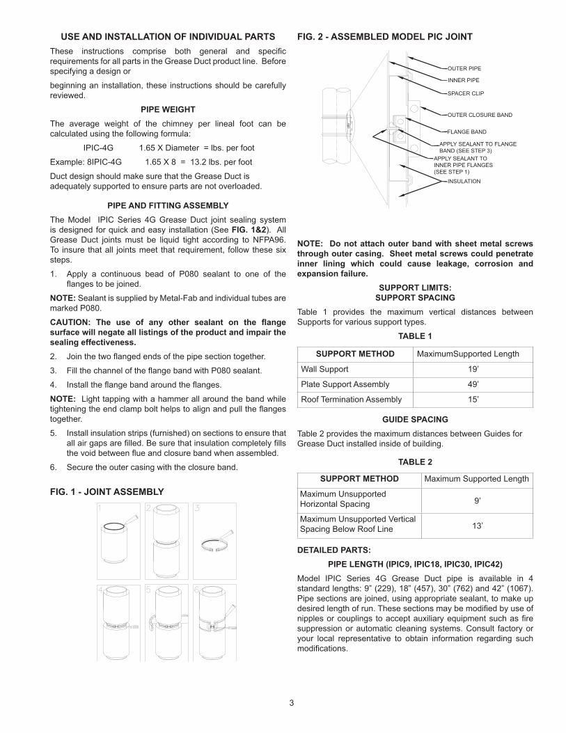
OUTER PIPE
INNER PIPE
SPACER CLIP
OUTER CLOSURE BAND
FLANGE BAND
INSULATION
APPLY SEALANT TO INNER PIPE FLANGES (SEE STEP 1)
APPLY SEALANT TO FLANGE BAND (SEE STEP 3)
USE AND INSTALLATION OF INDIVIDUAL PARTSThese instructions comprise both general and specific requirements for all parts in the Grease Duct product line. Before specifying a design or
beginning an installation, these instructions should be carefully reviewed.
PIPE WEIGHTThe average weight of the chimney per lineal foot can be calculated using the following formula:
IPIC-4G 1.65 X Diameter = lbs. per foot
Example: 8IPIC-4G 1.65 X 8 = 13.2 lbs. per foot
Duct design should make sure that the Grease Duct is adequately supported to ensure parts are not overloaded.
PIPE AND FITTING ASSEMBLYThe Model IPIC Series 4G Grease Duct joint sealing system is designed for quick and easy installation (See FIG. 1&2). All Grease Duct joints must be liquid tight according to NFPA96. To insure that all joints meet that requirement, follow these six steps.
1. Apply a continuous bead of P080 sealant to one of the flanges to be joined.
NOTE: Sealant is supplied by Metal-Fab and individual tubes are marked P080.
CAUTION: The use of any other sealant on the flange surface will negate all listings of the product and impair the sealing effectiveness.2. Join the two flanged ends of the pipe section together.
3. Fill the channel of the flange band with P080 sealant.
4. Install the flange band around the flanges.
NOTE: Light tapping with a hammer all around the band while tightening the end clamp bolt helps to align and pull the flanges together.
5. Install insulation strips (furnished) on sections to ensure that all air gaps are filled. Be sure that insulation completely fills the void between flue and closure band when assembled.
6. Secure the outer casing with the closure band.
FIG. 1 - JOINT ASSEMBLY
FIG. 2 - ASSEMBLED MODEL PIC JOINT
NOTE: Do not attach outer band with sheet metal screws through outer casing. Sheet metal screws could penetrate inner lining which could cause leakage, corrosion and expansion failure.
SUPPORT LIMITS: SUPPORT SPACING
Table 1 provides the maximum vertical distances between Supports for various support types.
TABLE 1
SUPPORT METHOD MaximumSupported Length
Wall Support 19’
Plate Support Assembly 49’
Roof Termination Assembly 15’
GUIDE SPACINGTable 2 provides the maximum distances between Guides for Grease Duct installed inside of building.
TABLE 2
SUPPORT METHOD Maximum Supported Length
Maximum Unsupported Horizontal Spacing 9’
Maximum Unsupported Vertical Spacing Below Roof Line 13’
DETAILED PARTS:PIPE LENGTH (IPIC9, IPIC18, IPIC30, IPIC42)
Model IPIC Series 4G Grease Duct pipe is available in 4 standard lengths: 9” (229), 18” (457), 30” (762) and 42” (1067). Pipe sections are joined, using appropriate sealant, to make up desired length of run. These sections may be modified by use of nipples or couplings to accept auxiliary equipment such as fire suppression or automatic cleaning systems. Consult factory or your local representative to obtain information regarding such modifications.
3

SQUARE TO ROUND ADAPTER (IPICSTR)When the hood is equipped with a square or rectangular collar, a square to round adapter is needed to connect the round IPIC pipe to the hood (See FIG. 3). The outside dimensions of the square end are slightly smaller than the hood collar. It will fit inside the collar and be connected by means of a lap weld. Alternatively, the square end may be equipped with a flange to be used for a bolted or welded connection in accordance with NFPA 96.
FIG. 3 - SQUARE TO ROUND ADAPTER
When ordering a square to round adapter, the size of the square end, flange requirements and diameter of the round end must be specified.
NOTE: Many hood manufacturers have the capability to build the hood with a round flanged collar, which matches the flange on Model IPIC pipe. Others can install a round flanged collar supplied to them or can provide a hood without a collar for the hole to be field cut. These alternatives may avoid the necessity of providing a square to round adapter.
GREASE MANIFOLD TEE (IPICGMT)The grease manifold tee is used to provide access for cleanout to comply with NFPA 96 requirements. It is equipped with a 11⁄2” (38) high grease dam at the access port. The access port must be closed with a cleanout cap (IPICTCN) or tee cap (IPICTC).
The location of the access port in the tee is dependent on the orientation of the tee in the final installation. Access port location is coded as Position 1, 2, 3, 4 or 5 (See FIG. 4). For tool-less access for inspection and maintenance (required by some jurisdictions) refer to section Access Panel (IPICTAP) and FIG. 4a.
FIG. 4 - GREASE MANIFOLD TEE ACCESS PORT LOCATIONS
GREASE DAM
POSITION #1 POSITION #2
POSITION #4 POSITION #5POSITION #3
OPTIONAL
TOOL-LESS ACCESS PANEL (IPICTAP)Tool-less access panels are available in duct sizes from 6”(152) to 36”(914) diameter. The IPICTAP is offered as an alternative to the IPICTCN to allow complete access for inspection and cleaning without the use of tools and complies with requirements of NFPA 96 for accessibility. The IPICTAP is designed to retrofit existing installations that use a clean out cap (IPICTCN). Assembly is shown (See FIG. 4a).
FIG. 4a - TOOL-LESS ACCESS PANEL ASSEMBLY
FAN / CURB TERMINATIONThe Fan / Curb termination is designed to be used in place of traditional curb / welded duct assembly. The Fan / Curb Termination is intended to be located and installed on a roof to serve as a fan curb with a self contained grease duct. The square termination is designed to directly connect to hinged type exhaust fans normally used for cooking fume extraction.
INSTALLATION: Prior to installing the Fan / Curb Termination, determine exact location that the grease duct system shall penetrate the roof. Cut a circular hole 1/4-inch larger than the diameter of the outer casing of the termination assembly.
Prior to installing the Fan / Curb Termination determine if adequate support by the roof assembly is available. In some applications, the Fan / Curb Termination will be used to support the total weight of the grease duct system and therefore additional cross supports for the roof may be required (See FIG. 5).
FIG. 5 - FAN / CURB TERMINATION
FLANGE BAND (SEALS BASE PLATE TO DUCT)
ACCESS COVER BASE PLATE
ACCESS COVER (WITH HIGH TEMP SEAL GASKET)
ACCESS COVER CASING
ROOF SURFACE
ATTACH PLATE TO ROOF USING SAME METHODS AS FOR ROOF CURB FLANGES
PRE-CUT HOLE 1/4-INCH LARGER THAN THE O.D. OF DUCT CASING
STEEL JOISTS
ADDITIONAL ANGLE IRON WELDED TO ROOF JOISTS FOR ADDED SUPPORT OF TERMINATION ASSEMBLY
4
When a duct over 20” (508) diameter is used, a reduced tap 90º manifold tee may be used in lieu of the grease tee. Note that the tap must be at least 20” (508) in diameter.

Once adequate support is available, install Fan / Curb Termination onto roof surface. The Fan / Curb Termination might require shimming in order to be level on the mounting surface. Attach Fan / Curb Termination plate to roof surface using similar methods used to secure roof curb to roof surface. Final sealing of roof surface should be applied after Fan / Curb Termination is installed or additional sealing of penetration will be required, as normally required for roof curb installations.
FIG. 6 - ROOF TERMINATION ASSEMBLY
90° WYE (IPIC90Y)The 90° is used where the Grease Duct must be accessed for clean-outs. It can be used in place of a 90° Tee and provides excellent access clearance for clean-outs (See FIG. 11).
ELBOWS 30°, 45°, OR 90° FIXED (IPIC30L, IPIC45L, OR IPIC90L)
The combination of (2) 30L or a 30L and a 45L will allow for offsets of 60° or 75°. The 90L is used to transition from horizontal to vertical and requires a clean-out at the change in direction. Elbows are not designed for resisting bending loads, therefore they must be protected from these conditions. (See FIG. 6 for structural recommendations to protect the elbows.)
FIG. 6 - METHODS OF STRUCTURAL REINFORCEMENT FOR ELBOWS
OFFSETSOffsets should be avoided except when there is no other way to route the Grease Duct. When an offset must be used, good design indicates that the angle used should be the minimum possible (See FIG. 8).
FIG. 7 - MINIMUM ELBOW OFFSETS (REFER TO TABLE 3)
Table 3 indicates minimum center to center offset for two elbows connected directly to each other.
FIG. 8 - SUPPORT FOR OFFSETS
ROOF LINE
FAN CURB TERMINATION ASSEMBLY
P080 SEALANT OR GASKET
FAN (BY OTHERS)
FCT PLATE
TOP VIEW
SIDE VIEW
ANGLE BRACING
PLATE SUPPORT
45° FIXED ELBOW
ANGLE BRACING
PLATE SUPPORT
2 EACH 45° ELBOWS REINFORCED WITH PLATE SUPPORTS
PLATE SUPPORT
WALL SUPPORT
ANGLE BRACING
45° FIXED ELBOW
ANGLE BRACING
2 EACH 45° ELBOWS REINFORCED WITH WALL SUPPORTS
TOP VIEW
SIDE VIEW
“A”
30° FIXED ELBOW OR 45° FIXED ELBOW
30° FIXED ELBOWOR 45° FIXED ELBOW EXPANSION JOINT
WALL SUPPORT ASSY. OR PLATE SUPPORT
EXPANSION JOINT
PLATE
WALL SUPPORT ASSY. OR PLATE SUPPORT
EXPANSION JOINT
EXPANSION JOINT
45° FIXED ELBOW
HALF ANGLE RING
FAN CURB TERMINATION
FAN
30° MAX. FOR OIL OR SOLID FUEL
5

Bracing, above and below the elbows, is needed to avoid subjecting them to bending moments. In order for bracing to be effective, it must be rigidly attached to building members or foundation. The design of the structure used to attach supports must include the weight of the sloped section and whatever additional pipe is carried by the support. Additionally, an expansion joint is needed between the elbows to relieve thermal expansion stresses.
TABLE 3 (MODEL IPIC SERIES 4G)(See FIG. 7 )
MINIMUM ELBOW OFFSETS
PIPE SIZE “A” - 30° ELBOW “A” - 45° ELBOW
6”8”10”12”14”16”18”20”22”24”26”28”30”32”34”36”
6” (152)7 3/4” (197)7 3/4” (197)7 3/4” (197)7 3/4” (197)7 3/4” (197)7 3/4” (197)8 1/2” (216)8 1/2” (216)8 1/2” (216)8 1/2” (216)8 1/2” (216)8 1/2” (216)
11” (279)11” (279)11” (279)
9 7/8” (251)14 1/8” (359)14 1/2” (368)14 1/2” (368)14 1/2” (368)14 1/2” (368)14 1/2” (368)16 5/8” (422)16 5/8” (422)16 5/8” (422)16 5/8” (422)16 5/8” (422)16 5/8” (422)19 3/4” (503)19 3/4” (503)19 3/4” (503)
TEE CAPS (IPICTC, IPICTCN)The Tee Cap provides access for cleaning and inspection into the Grease Duct. When using clean-outs, always prevent leaks and assure that the Grease Duct functions as intended. The Tee Caps can be ordered with or without a drain and are assembled in the same manner as the sections (See FIG. 1).
EXPANSION JOINT (IPICAL)The expansion joint may be used to compensate for thermal expansion and to make up odd lengths. It is essential that sufficient installed length be allowed to compensate for abnormal, as well as normal, operating conditions. The expansion joint cannot be used to correct misalignment or to compensate for lateral movement or vibration.
An expansion joint is comprised of: (1) a collar that is 51⁄4” (133) long with a flange and vee band at one end and a graphite impregnated ring gasket at the other; (2) a 30” (762) long tube, flanged at one end, which fits into the 51⁄4” (133) collar; (3) an outer jacket consisting of two half jacket assemblies; and (4) loose insulation blanket to fill space between the tube and casing.
FIG. 9 - EXPANSION JOINT FLUE ASSEMBLY
INSTALLATION PROCEDURE IS AS FOLLOWS:1. Loosen draw screw at gasket band and slide collar toward
flanged end of tube. Do not remove collar from tube.
2. Slide unflanged end of tube into the upstream piece of pipe and make up joint between pipe and collar following the procedures outlined under heading PIPE AND FITTING ASSEMBLY on Page 3.
3. Pull flanged end of tube to the downstream piece of pipe and make up joint as shown (See FIG. 9).
4. Cut insulation to desired length and wrap inner pipe ensuring that it is covered completely before attaching half jackets.
5. Wrap two half jackets around joint with bead at the downstream end and punched edge overlapping plain edge by approximate 3/4” (19). Note: For horizontal installations the seams must be located at the top and bottom of the pipe, coat unpunched edge of casing with P077 sealant to waterproof the casing.
6. Install self-drilling screws (supplied with jacket) at punched holed through both layers at overlap. Exercise care that half jacket edges do not align with draw screws on flange bands and that no screws are installed in portion of jacket which is over casing of adjacent pieces of pipe (See FIG. 10). The screws shipped with the expansion joint are of the correct length to avoid penetrating the inner wall (flue) of the pipe. Do not use any other screws to attach the casing.
FIG. 10 - EXPANSION JOINT CASING ASSEMBLY
30”(762) MAX. OR TRIMMED AS REQ’D
8”(203) MIN. INSTALLED LENGTH (22” MAX.)
5 1/4” (133)
COLLAR TUBE
AIR
SCREWS (INCLUDED)
3/4” (19)
NOTE: Do not screw through casing of adjacent pipe.
HALF JACKET
NOTES:1. It is recommended that the pipe on both sides of the
expansion joint is supported or guided to assure that the expansion joint will not bind during operation.
2. Installation of an expansion joint adjacent to fittings, such as elbows, tees or wyes, is not recommended. However, it is not always possible to avoid these fittings. If an expansion joint must be joined to one of these fittings, the unflanged end of the tube should be away from the fitting and fitted into a pipe length in the manner described in the installation procedure above.
3. Expansion joint must be installed with a flange to flange length of not more than 22” (558). The minimum length for installation must take into account the amount of expansion that may occur during operation. Minimum length is calculated as follows:
Expansion = Length (feet)/100 x Temperature Rise (ºF)/100
Minimum Length = Expansion + 6” (152mm)
It is recommended that the temperature used in the above formula be at least 300ºF higher than the expected normal operating temperature.
6

4 If inner tube is too long, it may be cut to length. Tube must be a minimum of 8”(203) longer than flange-to-flange length. Prior to installtion of cut pipe, remove all burrs to ensure that interference does not occur.
5. Check gasket to ensure that it fits snugly without binding on inner pipe.
6. Outer jacket must move during expansion or contraction. Ensure that no screws are located where the jacket overlaps the casing of the adjacent pipe and that it is loose enough to move as needed.
7. Alignment of the bead on the jacket with the bead on the adjacent pipe to ensure that the jacket stays in the proper location.
8. Note that the expansion joint will not support any weight in the vertical position. It should not be unless both end of run, where an expansion joint is installed, are anchored as fixed points.
FIG. 11 - EXPANSION JOINT LOCATION
CURB
IPICAL
PICPS
IPICFAR
IPICFAP
EXHAUST
IPICPPK
IPIC
GM
T
IPIC
TC
N
IPIC
PS
IPIC
HA
R
IPIC
AL
APPL.
HOOD
IPICTCNIPIC90Y
VARIABLE LENGTH (IPICVL)The function of the variable length is to make up odd lengths of pipe, which are not to be used for expansion compensation. The variable length is comprised of the following components: (1) a 31⁄4” (83) collar with a flange at one end used to clamp the flange at the desired length; (2) a 30” (762) long tube flanged at one end, which fits into the 31⁄4” (83) collar; (3) an outer jacket consisting of two half jacket assemblies; and (4) loose insulation blanket to fill space between the tube and casing.
A variable length can be installed at any flange to flange length from 4”-26” (102-660). If the flue is too long to fit into the adjacent section of pipe without interfering with the flow path, it should be trimmed to the desired flange to flange length plus 4” (102).
INSTALLATION PROCEDURE IS AS FOLLOWS:1. Loosen draw screw at collar and slide collar toward flanged
end of tube. Do not remove collar from tube.
2. Slide unflanged end of tube into the upstream piece of pipe. Pull flanged end of tube to the downstream piece of pipe and make up joint as outlined under PIPE AND FITTING ASSEMBLY on Page 3.
FIG. 12 - VARIABLE LENGTH FLUE ASSEMBLY30”(762) MAX. OR TRIMMED AS REQ’D
4”(102) MIN. INSTALLED LENGTH (22” MAX.)
3” (76.5)
COLLAR TUBE
3. Apply a thin coat of sealant, about 1” (25) wide at the plain end of the pipe where tube slides into mating pipe section. Press sealant into any gap between the tube and the mating pipe section. Apply sealant to flange of mating pipe (See FIG. 12).
4. Slide collar into position against flange of mating pipe. Fill flange band with sealant and install flange band.
5. Tighten bolts on clamp collar to complete installation. (For more positive seal, apply sealant to clamp collar slot and flared end of collar prior to tightening bolts).
6. Cut insulation to desired length and wrap inner pipe ensuring that it is covered completely before attaching half jackets.
7. Wrap two half jackets around joint with bead at the downstream end and punched edge that overlap the plain edge by approximately 3/4” (19).
NOTE: For horizontal installations, the seams must be located at the top and bottom of the pipe. Coat unpunched edge of casing with P077 sealant to waterproof the casing. Install self-drilling screws (supplied with jacket) at punched holed through both layers at overlap. Exercise care that half jacket edges do not align with draw screws on flange bands, and that no screws are installed in portion of jacket which is over casing of adjacent pieces of pipe (See FIG. 13). The screws shipped with the expansion joint are of the correct length to avoid penetrating the inner wall (flue) of the pipe.
Do not use any other screws to attach the casing.
SCREWS (INCLUDED)
3/4” (19)
HALF JACKET
FIG. 13 - VARIABLE LENGTH CASING ASSEMBLY
NOTES:1. It is recommended that the pipe adjacent to the variable
length is supported or guided to prevent sagging.
2. If a variable length must be installed adjacent to a tee, elbow, wye or other fitting where tube can interfere with flow, the unflanged end of the tube should be away from the fitting and fitted into a pipe length in the manner described in the installation procedure under FIG. 12.
7
FILLET AND BACKWELD ALL FRAMINGAND BRACING MEMBERS
CLAMP FLANGE PLATE SUPPORT
BRACING
“X” is a minimum of 30° when bracing is used. A welded frame must be adequately attached to structural member for framework rigidity if bracing isn’t used.
CASING BAND ENCLOSURE KITAfter exhaust head is attached to grease duct system, install aCasing Band Enclosure Kit which consists of insulation to wrap around the joint band and a casing band to finish the enclosure (See FIG. 14).
Joint connections are same as for pipe joints (See FIG. 1, Joint Assembly).
FIG. 14 - INSTALLED CASING BAND ENCLOSURE KIT
CASING BAND ENCLOSUREFLANGE BAND
INSULATION
FLUE
CASING
HOOD
PLATE SUPPORT (IPICPS)NOTE: See TABLE 2 for maximum supported height.
The plate support assembly is designed to provide maximal support to vertical sections and to provide fixed-point support for horizontal sections. The plate support must be attached to the building structure or support with rigid structural members.
FIG. 15 - PLATE SUPPORT BRACING REQUIREMENTS
Pipe Diameter
IPICPS Plate
Thickness
Bracing for IPIC Plate SupportHeight of Stack
35’ (10.67m) 75’ (22.86m)
6” - 20” 3/16” (5) 1 1/4”x1 1/4”x1/8” (32x32x3)
2”x2”x1/4” (51x51x6)
Pipe Diameter
IPICPS Plate
Thickness
Framework for IPIC Plate SupportHeight of Stack
35” (10.67m) 75’ (22.86m)
6” - 20” 3/16” (5) 1 3/4”x1 3/4”x1/8” (44x44x3)
3”x2”x3/16”(76x51x5)
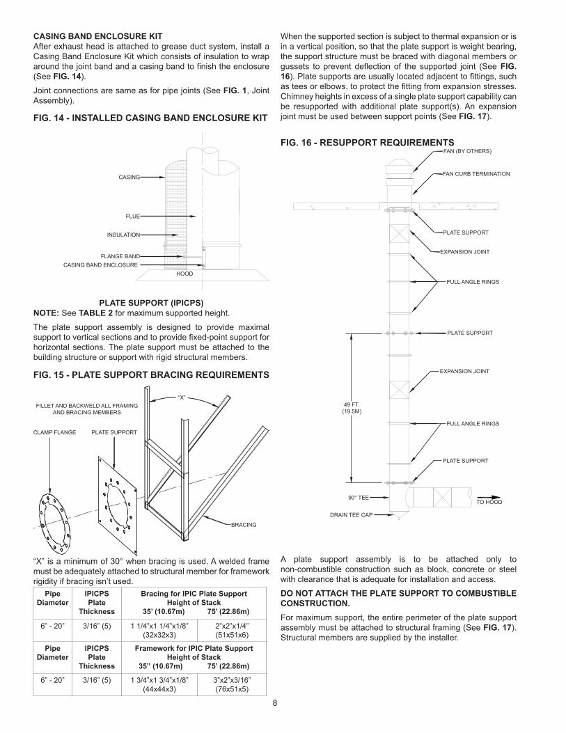
When the supported section is subject to thermal expansion or is in a vertical position, so that the plate support is weight bearing, the support structure must be braced with diagonal members or gussets to prevent deflection of the supported joint (See FIG. 16). Plate supports are usually located adjacent to fittings, such as tees or elbows, to protect the fitting from expansion stresses. Chimney heights in excess of a single plate support capability can be resupported with additional plate support(s). An expansion joint must be used between support points (See FIG. 17).
FIG. 16 - RESUPPORT REQUIREMENTSFAN (BY OTHERS)
FAN CURB TERMINATION
EXPANSION JOINT
PLATE SUPPORT
FULL ANGLE RINGS
PLATE SUPPORT
EXPANSION JOINT
FULL ANGLE RINGS
PLATE SUPPORT
TO HOOD
DRAIN TEE CAP
90° TEE
49 FT.(19.5M)
A plate support assembly is to be attached only to non-combustible construction such as block, concrete or steel with clearance that is adequate for installation and access.
DO NOT ATTACH THE PLATE SUPPORT TO COMBUSTIBLE CONSTRUCTION. For maximum support, the entire perimeter of the plate support assembly must be attached to structural framing (See FIG. 17). Structural members are supplied by the installer.
8
“X”

FIG. 17 - SECTIONAL DETAIL FOR PLATE SUPPORT
FLUE
FLANGE BAND
STRUCTURAL BRACING
(BY OTHERS)
PLATE SUPPORT
CLAMP RING
CASING
FULL ANGLE RING (IPICFAR) AND HALF ANGLE RING (IPICHAR)
The full angle ring is used as a guide to prevent the Grease Duct from flexing due to lateral loading. The angle ring is split for ease of installation. The I.D. of angle ring is slightly larger than the outside diameter of the pipe casing to allow movement of the pipe inside the ring (See FIG. 18).
FIG. 18 - FULL ANGLE RING & HALF ANGLE RING
HALF ANGLE RING
FULL ANGLE RING
The half angle ring is used as a saddle in horizontal or sloped runs. It may be suspended either on rigid framework or soft frames, such as threaded rod. The half angle ring will not replace a plate support or other fixed support in horizontal runs. It should not be used as the sole support for the Grease Duct.
THROUGH-PENETRATION FIRESTOP SYSTEMWhen penetrating a fire-resistance rated floor or wall, a Through-Penetration Firestop System is used to retain the fire resistance rating on the floor or walls. Use only the Model PICPPK (See FIG. 19).
1. Determine flue size of Grease Duct.
2. A circular hole that is 10” (254) greater than flue size, or 2.0 inches greater than duct O.D., is required in the masonry floor or wall.
3. Center the Series 4G Grease Duct within the hole. The duct is to be properly supported to maintain location.
4. Insert 3 1/2” (89) wide ceramic fiber provided. The fiber must encircle the outer casing of the grease duct and fill the cavity within 1/2” (13) of the floor (wall) surface. Pack the fiber within the cavity, if required.
5. On the down stream side of the floor or wall, closest to the appliance, apply the caulk provided, P082 3M Part Number CP25WB+, to a depth of 1/2” (13) deep around the duct.
NOTE: The openings between the grease duct and the floor (wall) must be closed.
6. Apply caulk to a depth of 1/2” (13) from the upstream side, filling the cavity.
7. Install two (2) halves of protector plate to the upstream side of the floor (wall). Secure with masonry hardware.
NOTE: The protector plate halves are designed to fit around the casing and overlap each other by 1/2” (13).
8. Position the closure band around the casing, making sure that between the closure band and the casing is the 12” (305) wide ceramic fiber provided. Secure the closure band.
NOTE: The closure band and ceramic fiber is designed to be touching the protector plates after installation (See FIG. 19).
FIG. 19 - 3 HOUR F, 3 HOUR T, THROUGH PENETRATION FIRESTOP
CONCRETE ANCHORS TYP.
(4) PLACES
CLOSURE BAND 0.035” THICK 304
STAINLESS STEEL
4 1/2 MIN.
CP25WB CAULK 1/2” DEEP X 1” THICK
1” CERAMICINSULATION
FLUE DIA. + 10”
CP25WB CAULK1/2” DEEP X 1” THICK
PROTECTOR PLATE IPICPP 0.035” THICK ALUMINIZED STEEL
1” CERAMIC INSULATION
MAINTENANCEGrease duct is required by NFPA 96 and many local building codes to be inspected and cleaned if necessary at specific intervals. Metal-Fab Model IPIC Grease Duct must be inspected and cleaned in accordance with local requirements. It requires no additional internal maintenance.
Metal-Fab recommends that grease containers connected to drainage points be emptied and washed out daily or more often, if necessary. If needed, the drain nipples should be checked and cleaned whenever the containers are emptied.
Where the duct is installed outside the building, the aluminized steel outer casing must be primed and painted. The paint surface should be maintained regularly to prevent possible deterioration of the casing surface. The use of stainless steel outer casing negates the need for painting.
9

AUTOMATIC CLEANINGAn automatic hot water/detergent cleaning system can be integrated into the IPIC Grease Duct by utilizing any of the specialized parts such as the Nozzle Section (IPICNS). All of the specialized parts have standard 1 inch diameter NPT coupling capabilities making attachment easy.
The typical water tempurature for automatic cleaning system is 160° F. and the entire duct system can be scrubbed down daily for the removal of grease and dirt depending on the application. Automatic cleaning systems should be connected to the correct hardware so that the residues from the process are directly piped to drains and not grease traps.
NOTE: When solid fuel fired cooking appliances are vented with Model IPIC Grease Duct, creosote and grease may buildup on the inner pipe wall. This mixture can result in an unusually severe duct fire. To minimize fire hazard, the duct should be inspected weekly and any residue removed by cleaning. Additional requirements for solid fuel fired cooking appliances are outlined in NFPA 96.
EXPECTED NUMBER OF JOINTS PER TUBE
(P080 SEALANT) Pipe Diameter No. of Joints Pipe Diameter No. of Joints Pipe Diameter No. of Joints
6” 5 22” 3 38” 1
8” 5 24” 2 40” 1
10” 5 26” 2 42” 1
12” 4 28” 2 44” 1
14” 4 30” 2 46” 1
16” 4 32” 2 48” 1
18” 3 34” 1
20” 3 36” 1
THE INFORMATION ON THIS PAGE PERTAINS TO ALL APPLICATIONS
NOTE: Sealant is supplied by Metal-Fab and individual tubes are marked P080-(3M #2000 Caulk).
CAUTION: The use of any other sealant on the flange surface will negateall listings of the product and impair the sealing effectiveness.
NOTE: Through Penetration Firestop System (PICPPK) is supplied with 3M&CP25WB+ firestop caulk in individual tubes marked P082. (Refer to Installation Instructions for further details.)
10

NOTES:
11

P.O. Box 1138 • WICHITA, KANSAS 67201(316) 943-2351 • 800-835-2830
FAX (316) [email protected] • www.metal-fabinc.com
©2005 Metal-Fab, Inc. Form No. L2056 7-05 768912