
Model Integration and Transformation A Triple Graph ... › 4cd9 › 5680e3fd29aea1f5a3ee558… ·...
174
Model Integration and Transformation – A Triple Graph Grammar-based QVT Implementation Vom Fachbereich 18 Elekrotechnik und Informationstechnik der Technischen Universität Darmstadt zur Erlangung der Würde eines Doktor-Ingenieurs (Dr.-Ing.) genehmigte Dissertation von Dipl.-Inform. Alexander Königs geboren in Krefeld-Hüls Referent: Prof. Dr. rer. nat. Andy Schürr Korreferent: Prof. Dr. rer. nat. Gregor Engels Tag der Einreichung: 01.07.2008 Tag der mündlichen Prüfung: 31.10.2008 D17 Darmstadt 2009
Transcript of Model Integration and Transformation A Triple Graph ... › 4cd9 › 5680e3fd29aea1f5a3ee558… ·...

Model Integration and Transformation–
A Triple Graph Grammar-basedQVT Implementation
Vom Fachbereich 18Elekrotechnik und Informationstechnikder Technischen Universität Darmstadt
zur Erlangung der Würdeeines Doktor-Ingenieurs (Dr.-Ing.)
genehmigte Dissertation
von
Dipl.-Inform. Alexander Königs
geboren in Krefeld-Hüls
Referent: Prof. Dr. rer. nat. Andy SchürrKorreferent: Prof. Dr. rer. nat. Gregor EngelsTag der Einreichung: 01.07.2008Tag der mündlichen Prüfung: 31.10.2008
D17Darmstadt 2009

ii

Danksagung
Die vorliegende Arbeit wäre ohne die Hilfe, Unterstüzung und den Beistand einerganzen Reihe von Leuten nicht möglich gewesen. Daher möchte ich mich herz-lich bei Allen bedanken, die auf die ein oder andere Art und Weise direkt oderindirekt zu dieser Arbeit beigetragen haben.Im Einzelnen möchte ich besonders folgenden Personen danken:Meinem Doktorvater Professor Andy Schürr für die Chance zur Promotion,die beispiellose Betreuung meiner Arbeit, zahlreiche ergiebige Diskussionen,wertvolle Anregungen und seine große Geduld. Für seine Tätigkeit als ersterGutachter und Prüfer und nicht zuletzt als großartiger Chef.Professor Gregor Engels für seine Bereitschaft, die Rollen des zweiten Gutachtersund Prüfers zu übernehmen.Den Professoren Ralf Steinmetz und Jürgen Adamy als dritte bzw. vierte Prüfer.Tobias Rötschke und Johannes Jakob nicht nur als Kollegen, sondern vor allemauch als Freunde für zahlreiche, zum Teil leidenschaftlich geführte Diskussio-nen, gegenseitige Motivation und Freizeit in Form von Pool Billard, Poker undTischfußball.Felix Klar für seine unermüdliche Unterstützung bei der Realisierung unseresTGG-Ansatzes und dessen Fortführung.Carsten Amelunxen, Markus Schmidt und Oliver Alt als geschätzte Kollegen derersten Stunde.Elodie Legros, Ingo Weisemöller und Patrick Mukherrje als die zweite Generationvon wissenschaftlichen Mitarbeitern am Fachgebiet.Den zahlreichen Studenten, vor allem Emre Karaca, die durch ihre Studien-,Bachelor-, Diplom- und Master-Arbeiten und ihre Tätigkeiten als studentischeHilfskräfte die Grundlage für die vorliegende Dissertation geschaffen haben.Unserem technischen Administrator Ingo Heip für seinen beispiellosen Einsatz,eine ausgezeichnete technische Infrastruktur bereitzustellen, und das Einweihenin die Geheimnisse des Geocachings.Meinen Freunden und nicht zuletzt meiner Mutter und meiner Großmutter für diemoralische Unterstützung und Motivation, ohne die diese Arbeit nicht möglichgewesen wäre.
iii

Contents
List of Figures vii
1 Introduction 31.1 Motivation . . . . . . . . . . . . . . . . . . . . . . . . . . . . . . 31.2 Scope . . . . . . . . . . . . . . . . . . . . . . . . . . . . . . . . 61.3 Case studies . . . . . . . . . . . . . . . . . . . . . . . . . . . . . 71.4 Contributions . . . . . . . . . . . . . . . . . . . . . . . . . . . . 91.5 Overall picture . . . . . . . . . . . . . . . . . . . . . . . . . . . 101.6 Outline . . . . . . . . . . . . . . . . . . . . . . . . . . . . . . . 11
2 Metamodeling 122.1 MDA . . . . . . . . . . . . . . . . . . . . . . . . . . . . . . . . 122.2 MOF . . . . . . . . . . . . . . . . . . . . . . . . . . . . . . . . . 142.3 OCL . . . . . . . . . . . . . . . . . . . . . . . . . . . . . . . . . 19
3 QVT 213.1 Running example . . . . . . . . . . . . . . . . . . . . . . . . . . 213.2 Request For Proposal . . . . . . . . . . . . . . . . . . . . . . . . 253.3 Specification . . . . . . . . . . . . . . . . . . . . . . . . . . . . 28
3.3.1 Basic concepts . . . . . . . . . . . . . . . . . . . . . . . 303.3.2 The Relational language . . . . . . . . . . . . . . . . . . 333.3.3 The Core language . . . . . . . . . . . . . . . . . . . . . 38
3.4 Shortcomings . . . . . . . . . . . . . . . . . . . . . . . . . . . . 40
4 Graph Grammars 454.1 String grammars . . . . . . . . . . . . . . . . . . . . . . . . . . . 454.2 Graph schemas . . . . . . . . . . . . . . . . . . . . . . . . . . . 464.3 Basic rule elements . . . . . . . . . . . . . . . . . . . . . . . . . 474.4 Sophisticated rule elements . . . . . . . . . . . . . . . . . . . . . 494.5 Pair and Triple Graph Grammars . . . . . . . . . . . . . . . . . . 51
5 TGG schema language 55
iv

5.1 Package dependencies . . . . . . . . . . . . . . . . . . . . . . . 555.2 Basic integration link type concepts . . . . . . . . . . . . . . . . 565.3 Sophisticated integration link type concepts . . . . . . . . . . . . 595.4 Mapping to QVT Relational . . . . . . . . . . . . . . . . . . . . 65
6 TGG rule language 686.1 Basic elements . . . . . . . . . . . . . . . . . . . . . . . . . . . 686.2 Sophisticated elements . . . . . . . . . . . . . . . . . . . . . . . 706.3 Mapping to QVT Relational . . . . . . . . . . . . . . . . . . . . 73
7 Operational rules 767.1 Derivation strategies . . . . . . . . . . . . . . . . . . . . . . . . 76
7.1.1 Classical rules . . . . . . . . . . . . . . . . . . . . . . . 777.1.2 Additional rules . . . . . . . . . . . . . . . . . . . . . . . 777.1.3 Operational rule derivation . . . . . . . . . . . . . . . . . 787.1.4 Impact of where-dependencies on rule derivation . . . . . 85
7.2 Application strategies . . . . . . . . . . . . . . . . . . . . . . . . 857.3 On negative application conditions . . . . . . . . . . . . . . . . . 93
8 Realization 978.1 The MOFLON meta-CASE tool . . . . . . . . . . . . . . . . . . 978.2 MOFLON TGG plug-in . . . . . . . . . . . . . . . . . . . . . . . 100
8.2.1 The TGG schema editor . . . . . . . . . . . . . . . . . . 1038.2.2 The TGG rule editor . . . . . . . . . . . . . . . . . . . . 1088.2.3 Code generation . . . . . . . . . . . . . . . . . . . . . . 109
8.3 Integrator . . . . . . . . . . . . . . . . . . . . . . . . . . . . . . 1128.4 Linkbrowser . . . . . . . . . . . . . . . . . . . . . . . . . . . . . 116
9 Application 1209.1 The ToolNet project . . . . . . . . . . . . . . . . . . . . . . . . . 1209.2 Enterprise Architect to Matlab/Simulink transformation . . . . . . 123
10 Related work 13310.1 Categorization criteria . . . . . . . . . . . . . . . . . . . . . . . 13310.2 Common approaches . . . . . . . . . . . . . . . . . . . . . . . . 13610.3 Graph Grammar-based approaches . . . . . . . . . . . . . . . . . 13810.4 TGG-based approaches . . . . . . . . . . . . . . . . . . . . . . . 13910.5 QVT-based approaches . . . . . . . . . . . . . . . . . . . . . . . 140
v
10.6 Summary . . . . . . . . . . . . . . . . . . . . . . . . . . . . . . 142
11 Conclusion 14411.1 Open issues . . . . . . . . . . . . . . . . . . . . . . . . . . . . . 14611.2 Future work . . . . . . . . . . . . . . . . . . . . . . . . . . . . . 14711.3 Closing words . . . . . . . . . . . . . . . . . . . . . . . . . . . . 150
A Running example 151
B Curriculum vitae 159
Bibliography 160
vi

List of Figures
1.1 Well-known process models . . . . . . . . . . . . . . . . . . . . 41.2 Example of a tool chain in a system development process . . . . . 51.3 Composition of the MOFLON Specification Language (MOSL) . 10
2.1 The MDA approach . . . . . . . . . . . . . . . . . . . . . . . . . 132.2 OMG’s modeling layers . . . . . . . . . . . . . . . . . . . . . . . 142.3 Package structure of MOF . . . . . . . . . . . . . . . . . . . . . 152.4 Cut-out of MOF’s metamodel taken from [OMG06a] . . . . . . . 172.5 Package concepts of MOF taken from [OMG07] . . . . . . . . . . 182.6 Exemplary application of OMG’s layered modeling architecture . 182.7 Exemplary metamodel a. without and b. with an OCL constraint . 19
3.1 Metamodel for class diagrams . . . . . . . . . . . . . . . . . . . 223.2 Metamodel for database schemas . . . . . . . . . . . . . . . . . . 233.3 Package structure of QVT . . . . . . . . . . . . . . . . . . . . . 293.4 QVTBase package taken from [OMG05b] . . . . . . . . . . . . . 313.5 QVTBase package taken from [OMG05b] (cont.) . . . . . . . . . 313.6 QVTTemplate package taken from [OMG05b] . . . . . . . . . . . 323.7 QVTRelation package taken from [OMG05b] . . . . . . . . . . . 333.8 Examples of QVT’s graphical syntax . . . . . . . . . . . . . . . . 353.9 QVTCore package taken from [OMG05b] . . . . . . . . . . . . . 383.10 QVTCore package taken from [OMG05b] (cont.) . . . . . . . . . 393.11 Patterns in a QVT core mapping taken from [OMG05b] . . . . . . 403.12 Part of QVT’s metamodel a. incomplete, b. completed . . . . . . 41
4.1 Example of a. a graph schema and b. a conforming graph . . . . . 474.2 Example of a. normal graph rules and b. collapsed rules . . . . . 484.3 Example of a. sophisticated graph rules and b. collapsed rules . . 504.4 Example of a pair grammar . . . . . . . . . . . . . . . . . . . . . 534.5 Application of a pair grammar . . . . . . . . . . . . . . . . . . . 54
5.1 TGGs::Packages diagram . . . . . . . . . . . . . . . . . . . . . . 56
vii

5.2 Package hierarchy of our TGG approach . . . . . . . . . . . . . . 575.3 TGGs::IntegrationLinkTypes diagram . . . . . . . . . . . . . . . 585.4 Basic concepts of a TGG schema . . . . . . . . . . . . . . . . . . 595.5 TGG rule a. without and b. with parameter . . . . . . . . . . . . 625.6 Examples of a. a TGG rule without provided context, b. the dec-
laration of a where-dependency, and c. a TGG rule with providedcontext . . . . . . . . . . . . . . . . . . . . . . . . . . . . . . . . 64
5.7 Comparison of QVT Relational and TGGs . . . . . . . . . . . . . 65
6.1 TGGs::Rules diagram . . . . . . . . . . . . . . . . . . . . . . . . 696.2 TGG rule with a simple value specification . . . . . . . . . . . . . 706.3 TGG rule with complex value specification . . . . . . . . . . . . 716.4 Comparison of QVT Relational and TGGs (cont.) . . . . . . . . . 736.5 Comparison of a. a TGG rule and b. the corresponding QVT rule . 74
7.1 Derived model transformation rules . . . . . . . . . . . . . . . . 807.2 Derived consistency checking rule . . . . . . . . . . . . . . . . . 817.3 Derived link creation rules . . . . . . . . . . . . . . . . . . . . . 827.4 Derived attribute value propagation rules . . . . . . . . . . . . . . 837.5 Derived element deletion propagation rules . . . . . . . . . . . . 847.6 Derived link deletion rule . . . . . . . . . . . . . . . . . . . . . . 857.7 Example model for the illustration of application strategy related
problems . . . . . . . . . . . . . . . . . . . . . . . . . . . . . . 877.8 Example class diagram model . . . . . . . . . . . . . . . . . . . 907.9 Resulting database schema model . . . . . . . . . . . . . . . . . 917.10 a. Metamodel of linked lists, b. To be transformed source model . 947.11 a. Source part of the declarative model integration rules, b. De-
rived forward transformation rule parts with NACs, c. Derivedforward transformation rule parts with priorities . . . . . . . . . . 95
8.1 Tools and features for metamodeling taken from [AKRS03] . . . . 988.2 Overview of MOFLON’s architecture . . . . . . . . . . . . . . . 1008.3 Architecture of MOFLON’s TGG plug-in . . . . . . . . . . . . . 1018.4 Project diagram . . . . . . . . . . . . . . . . . . . . . . . . . . . 1038.5 Schema diagram . . . . . . . . . . . . . . . . . . . . . . . . . . . 1048.6 Package diagram . . . . . . . . . . . . . . . . . . . . . . . . . . 1058.7 Node diagram . . . . . . . . . . . . . . . . . . . . . . . . . . . . 1068.8 Node dependencies diagram . . . . . . . . . . . . . . . . . . . . 107
viii

8.9 Screenshot of the TGG schema editor . . . . . . . . . . . . . . . 1088.10 Rule diagram . . . . . . . . . . . . . . . . . . . . . . . . . . . . 1098.11 Screenshot of the TGG rule editor . . . . . . . . . . . . . . . . . 1108.12 Translation of TGGMultiplicities . . . . . . . . . . . . . . 1118.13 Screenshot of the SDM rule editor . . . . . . . . . . . . . . . . . 1128.14 Screenshot of the MOFLON-Integrator . . . . . . . . . . . . . . . 1138.15 Mapping of a MOF model to Java interfaces (taken from [Sun02]) 1148.16 Screenshot of the Matrixbrowser . . . . . . . . . . . . . . . . . . 118
9.1 Screenshot of the ToolNet desktop . . . . . . . . . . . . . . . . . 1219.2 Example of an integration rule of the ToolNet showcase . . . . . . 1239.3 Simplified metamodel of Enterprise Architect . . . . . . . . . . . 1249.4 Simplified metamodel of Matlab / Simulink . . . . . . . . . . . . 1259.5 Integration metamodel . . . . . . . . . . . . . . . . . . . . . . . 1269.6 ModelPackageToRootsystem rule . . . . . . . . . . . . . . 1279.7 ClassToSubsystemBlock rule . . . . . . . . . . . . . . . . 1289.8 PartToSubsystemBlock rule . . . . . . . . . . . . . . . . . 1309.9 InportToInport rule . . . . . . . . . . . . . . . . . . . . . . 1319.10 ConnectorToLine rule . . . . . . . . . . . . . . . . . . . . . 132
10.1 Comparison of various model integration approaches . . . . . . . 142
A.1 Metamodel for class diagrams . . . . . . . . . . . . . . . . . . . 152A.2 Metamodel for database schemas . . . . . . . . . . . . . . . . . . 153A.3 Integration metamodel . . . . . . . . . . . . . . . . . . . . . . . 154A.4 TGG rule PackageToSchema . . . . . . . . . . . . . . . . . . 155A.5 TGG rule ClassToTable . . . . . . . . . . . . . . . . . . . . 155A.6 TGG rule SubClassToTable . . . . . . . . . . . . . . . . . . 155A.7 TGG rule AttributeToColumn . . . . . . . . . . . . . . . . 156A.8 TGG rule PrimaryAttributeToColumn . . . . . . . . . . . 156A.9 TGG rule NonPersistentAttributeToColumn . . . . . . 157A.10 TGG rule NonPersistentAssocToColumn . . . . . . . . . 157A.11 TGG rule AttributeToFKey . . . . . . . . . . . . . . . . . . 158A.12 TGG rule AssocToFKey . . . . . . . . . . . . . . . . . . . . . 158
ix

x

Abstract
Nowadays, software and system development projects involve an increasing num-ber of various CASE tools each of which is specialized in certain tasks or phasesof the development process. This results in an unrelated distribution of the dataof a project as a whole over the different data repositories of the considered tools.The task of manually keeping the data consistent is cumbersome, time consuming,and error prone. Therefore, there is an urgent need for automatic support in dataconsistency checking and consistency enforcement. OMG’s Query / View / Trans-formation (QVT) standard provides a model-based language for the specificationof consistency checking and consistency enforcement rules. The QVT standardcurrently is implemented by a number of different groups but suffers from the factthat it lacks a proper formalization up to now. In contrast Triple Graph Grammars(TGGs) provide a declarative language for the specification of consistency check-ing and consistency enforcement rules based on the formal foundation of graphgrammars. However, TGGs lack some concepts provided by the QVT standardwhich are needed in practice to be applicable. This work transfers TGGs intoOMG’s world of metamodeling and extends them by the desired concepts fromQVT. The result is an TGG-based implementation of the QVT standard basedon the formalism of graph grammars. Furthermore, the presented approach willbe supplemented by a framework for automatically checking and enforcing theconsistency of distributed data of a considered development project as a whole.
1

Zusammenfassung
In der Software- und Systementwicklung kommen immer häufiger auf bestimmteAufgaben oder Phasen des Entwicklungsprozess zugeschnittene Werkzeuge zumEinsatz. Daraus resultiert eine lose Verteilung der Projektdaten über voneinanderunabhängige Datenspeicher. Die erforderliche Konsistenzhaltung der Daten istauf manuellem Weg sehr kostenintensiv und fehleranfällig. Deshalb ist eine au-tomatische Unterstützung zur Konsistenzprüfung und Konsistenzwiederherstel-lung wünschenswert. Der Query / View / Transformation (QVT) Standard derOMG definiert eine modellbasierte Sprache zur Spezifikation von Regeln zurangestrebten Prüfung und Wiederherstellung der Konsistenz von Daten. Derzeitarbeiten zahlreiche Gruppen an Implementierungen dieses Standards, dem esaber bis heute an einer formalen Grundlage fehlt. Tripel-Graph-Grammatiken(TGGen) hingegen bieten eine deklarative Sprache zur Spezifikation von Konsis-tenzprüfungs- und Konsistenzwiederherstellungsregeln auf der formalen Grund-lage von Graphgrammatiken. TGGen fehlt es allerdings an wichtigen in derPraxis benötigten Konzepten, die der QVT-Standard bietet. Diese Arbeit überträgtden Ansatz der TGGen auf die Metamodellierungswelt der OMG und erweitertihn um fehlende Konzepte des QVT-Standards. Ziel ist eine eigene Implemen-tierung des QVT-Standards, deren Semantik sich auf den bestehenden Formalis-mus der Graphgrammatiken stützt, angewandt von einem Rahmenwerk zur au-tomatischen Unterstützung zur Konsistenzhaltung und Konsistenzwiederherstel-lung von über voneinander unabängigen Datenspeichern verteilten Projektdaten.
2
1 Introduction
1.1 Motivation
Current software and system development process models subdivide the flow ofall involved activities into several phases or tasks (c.f. Fig. 1.1). For instance thewaterfall model [Som06] from Fig. 1.1a as a very simple and basic process modelintroduces phases as requirements specification, design, construction, integration,testing, installation, and maintenance.
The V-model [Som06] as presented in Fig. 1.1b contains a specification partwhich includes tasks as user requirements, functional, and design specifications.These specifications are then validated by a testing phase which includes tasks asinstallation, operational, and performance qualification.
Last but not least the Rational Unified Process (RUP) [Som06] from Fig. 1.1cdefines phases called inception, elaboration, construction, and transition. Eachphase involves tasks as business modeling, requirements elicitation, analysis anddesign, implementation, testing, deployment, configuration, and project and pro-cess management.
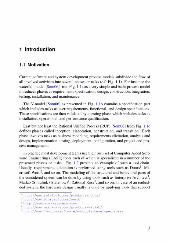
In practice most development teams use their own set of Computer Aided Soft-ware Engineering (CASE) tools each of which is specialized in a number of thepresented phases or tasks. Fig. 1.2 presents an example of such a tool chain.Usually, requirements elicitation is performed using tools such as Doors1, Mi-crosoft Word2, and so on. The modeling of the structural and behavioral parts ofthe considered system can be done by using tools such as Enterprise Architect3,Matlab (Simulink / Stateflow)4, Rational Rose5, and so on. In case of an embed-ded system, the hardware design usually is done by applying tools that support
1http://www.telelogic.com/products/doors/2http://www.microsoft.com/word/3 http://www.sparxsystems.com/4http://www.mathworks.com/products/matlab/5http://www.ibm.com/software/awdtools/developer/rose/
3

1 Introduction
RequirementsSpecification
Design
Construction
Integration
Testing
Installation
Maintenance
RequirementsSpecification
Design
Construction
Integration
Testing
Installation
Maintenance
a. b.
c.
Figure 1.1: Well-known process models
the hardware description language (HDL) as HDL Author6 for instance and thenmodeling the desired system using Computer Aided Design (CAD) tools such asCatia7. The desired test suites for testing the system under development can bespecified by tools such as CTE8. Finally, tools such as Windchill9 manage com-mon products’ data.
6http://www.mentor.com/products/fpga_pld/hdl_design/hdl_author/7http://www.3ds.com/products/catia/catia-discovery/8http://www.systematic-testing.com/9http://www.ptc.com/products/windchill/
4
1.1 Motivation
System requirements System Modeling
HW-Design
Function Test ECU-Housing
Product Data
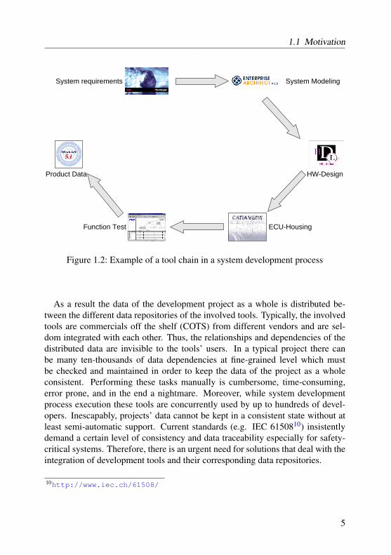
Figure 1.2: Example of a tool chain in a system development process
As a result the data of the development project as a whole is distributed be-tween the different data repositories of the involved tools. Typically, the involvedtools are commercials off the shelf (COTS) from different vendors and are sel-dom integrated with each other. Thus, the relationships and dependencies of thedistributed data are invisible to the tools’ users. In a typical project there canbe many ten-thousands of data dependencies at fine-grained level which mustbe checked and maintained in order to keep the data of the project as a wholeconsistent. Performing these tasks manually is cumbersome, time-consuming,error prone, and in the end a nightmare. Moreover, while system developmentprocess execution these tools are concurrently used by up to hundreds of devel-opers. Inescapably, projects’ data cannot be kept in a consistent state without atleast semi-automatic support. Current standards (e.g. IEC 6150810) insistentlydemand a certain level of consistency and data traceability especially for safety-critical systems. Therefore, there is an urgent need for solutions that deal with theintegration of development tools and their corresponding data repositories.
10http://www.iec.ch/61508/
5

1 Introduction
1.2 Scope
Concerning tool integration Brown [BCM+94] identifies three dimensions of in-tegration: Presentation, Control, and Data integration. Basically, presentationintegration aims at integrating tools by providing a uniform user interface for theconsidered tools. Either this can be achieved by a tool suite which tools rely onmore or less the same user interface or by using an integrated tool environmentsuch as the Eclipse platform for instance. Presentation integration is ineligiblewhen integrating COTS tools since the user interfaces of such tools are more orless immutable. Furthermore, presentation integration does not solve the problemof data consistency presented above. Therefore, presentation integration is outof scope for this work. Control integration aims at keeping the data of differenttools continuously consistent by notifying all tools about changes that occur ineach tool. Control integration is not applicable to our scenario because it requiressome sort of event notification mechanism that is seldom provided by COTS tools.Besides, continuously modifying the data of the to be integrated tools is not sat-isfactory. As mentioned before the different tools should be concurrently usableby hundreds of developers. On the one hand it seems to be a hard task to ef-ficiently handle the number of change events that might occur in a concurrentscenario with many users. On the other hand it would be undesirable that the dataa single developer is working on would continuously change due to changes madeby different users in different tools. Therefore, control integration is not suitablefor our intended scenario and, thus, is out of scope for this work. In this workwe put the focus on data integration. To this end we have to address the issuesData Persistence and Data Semantics according to [BCM+94]. Dealing with datapersistence means answering the question which data must be kept persistent andwhere. Furthermore, we must clarify in which way and to which degree data isshared by the to be integrated tools. Data semantics means specifying types ofdependencies between data of the considered tools and maintaining informationon actual dependencies at runtime.
In addition to the classification presented so far [BCM+94] subdivides inte-gration approaches into a-priori and a-posteriori integration approaches. A-prioriintegration approaches develop tools that are designed to easily integrate witheach other. A-posteriori integration approaches aim at integrating already exist-ing tools regardless whether or not they have been developed having integrationpurposes in mind. Since the latter usually applies to COTS tools we focus ona-posteriori tool integration in this work.
6

1.3 Case studies
1.3 Case studies
Traceability link creation
In our first case study our industrial partner DaimlerChrysler is facing the prob-lem to analyze which data objects in one tool correspond to which data objectsin another tool. In particular system requirements for a windscreen wiper with arain sensor are stored in the requirements elicitation tool Doors11. Furthermore,corresponding test case specifications are stored in a tool called CTE12 whichsupports the classification tree method for black-box testing purposes. In order tospecify which requirement is tested by a test case the number of the requirementis stored in the comment field of the regarded test case. Thus, a user is able tomanually check whether all requirements are checked by at least one test case.Since there normally are hundreds of requirements for a regarded system this ap-proach is cumbersome, time consuming, and error prone. The situation becomeseven worse if the user wants to determine all test cases that are assigned to a re-garded requirement. To address the latter issue DaimlerChrysler together with theTFH Berlin, University of Paderborn, and TU Darmstadt developed the ToolnetFramework [ADS02] which enables its users to manually create traceability linksbetween objects stored in different tools. Provided that all valid traceability linkshave been created beforehand it is very easy to check whether or not all require-ments are tested and which test cases are assigned to each requirement. However,Toolnet does not provide any support for automatically creating and validating theneeded traceability links. Therefore, our approach should offer such a support.
Model-Model consistency analysis
In another case study Philips Medical Systems is developing magnetic reso-nance tomographs [Röt09]. Philips is confronted with the situation that the devel-opers initially started the development without a proper architecture of the sys-tems in mind. In the meantime the systems have evolved over many generationsand Philips is running into maintenance problems. To address these problemsPhilips has specified a supposed system architecture and aims at modifying theirexisting systems in such a way that they meet the envisioned architecture one day.To this end Philips maps the existing source code of the regarded systems to thenew architectural concepts. After that Philips compares the current architectures
11http://www.telelogic.com/products/doors/12http://www.systematic-testing.com/
7

1 Introduction
with the desired ones and calculates a number of metrics. Thereby, one current ar-chitecture constitutes one model, whereas one desired architecture constitutes theother model. Since a metric is seldom useful as it is Philips rather keeps track ofthe evolution of the calculated metrics over time. This allows for a more sophis-ticated evaluation of whether or nor the architectures of the maintained systemsare converging with the desired architectures.
Model-Model transformation
In another case study our industrial partner from Bosch has to test their em-bedded automotive multimedia systems [Alt07]. Bosch wants to have support forspecifying test cases on an abstract level that considers categories of multime-dia systems (e.g. CD player, navigation system) rather than concrete products.In order to test a concrete product Bosch wants to automatically transform thecorresponding abstract test case specification into a test case for the consideredproduct. Therefore, Bosch needs support for specifying the transformation of anabstract test case into a corresponding concrete test case.
Running example
As a final case study we examine the task of automatically transforming a givenclass diagram into a corresponding database schema. We use this task as a run-ning example throughout this work for the following reasons. First of all, theexample is rather small and easy to understand. Nevertheless, the transformationof class diagrams into database schemas has proved to be more challenging thanmost examples with an industrial background. Therefore, this case study allowsus to introduce and explain the more sophisticated concepts of our approach indetail. Furthermore, this example has been part of the Model Transformation inPractice Workshop 200513. The participants of this workshop have been askedto tackle this transformation task using their own approaches. Finally, a solutionof this transformation task is included in the final QVT specification which is anupcoming model integration standard as introduced in detail in Chapter 3. Thus,this case study can be considered as an official benchmark for QVT-related modeltransformation approaches. We describe this case study in detail in Section 3.1.
13http://sosym.dcs.kcl.ac.uk/events/mtip05/
8

1.4 Contributions
1.4 Contributions
Having the mentioned case studies in mind we ultimately are aiming at an inte-grated approach that is able to identify and maintain traceability information be-tween two models, checks two models for consistency, and bidirectionally trans-form one model into another and vice versa.
To this end we investigate two already existing approaches that claim to be ableto cope with the intended model integration tasks. On the one hand we examinethe upcoming model integration standard QVT [OMG05b] from the OMG14. Onthe other hand we examine the graph grammar-based approach of TGGs. As wewill see later both approaches have their own edges and flaws. Therefore, weaim at combining both approaches in order to compensate the flaws of the oneapproach by the edges of the other approach and vice versa.
Particularly, we start with the initial TGG approach as presented by Schürr in1994 [Sch94]. This approach relies on the idea of declaratively specifying modelintegration rules from which operational rules can be derived automatically. Theresulting operational rules can be applied for model integration tasks such as cre-ating and validating traceability links between elements of the to be integratedmodels, forward and backward model transformation where one model is createdfrom the other and vice versa. We extend this set of classical model integrationrules by rules for deleting traceability links and bidirectionally propagating at-tribute value changes as well as the deletion of model elements.
Furthermore, we come up with strategies of how to apply the derived opera-tional rules automatically for realizing automatic model integration support. Tothis end we extend the initial TGG approach with the concept of priorities whichallows for the sophisticated resolution / avoidance of rule application conflicts.By adding parameters to the declaration of model integration rules we clarifythe concept of specifying attribute value expressions and their processing at rulederivation time. Moreover, we investigate the contended concept of Negative Ap-plication Conditions and decide to intentionally exclude them from our approachas they can often be simulated with the concept of priorities.
Finally, we adopt some very useful and user-friendly concepts from MOF andQVT. For instance, we adopt MOF’s concepts for modularization and reusability.Furthermore, we adopt the concept for explicitly controlling the rule application
14http://www.omg.org
9

1 Introduction
MOSL
MOF 2.0 OCL 2.0
SDM TGG
Figure 1.3: Composition of the MOFLON Specification Language (MOSL)
order from QVT. As a result we come up with a model integration approach thatthe reader hopefully considers to be highly expressive, user-friendly, and formallywell-defined.
1.5 Overall picture
This thesis presents work that has been done as part of the research activities ofthe Real-Time Systems Lab, TU Darmstadt, Germany. The general goal of ourlab is to provide a meta-CASE (Computer Aided Software Engineering) tool. Ameta-CASE tool is a CASE tool which can be used to specify and implementCASE tools. The tasks of the lab are to provide an appropriate and easy to usespecification language, implement a tool that allows for the application of thislanguage and generate corresponding code, and apply our approach to case studiesthat demonstrate the usefulness of our approach.
As we will discuss later on in detail we have chosen to realize the desired speci-fication language on the foundation of the Meta Object Facility (MOF) [OMG06a]and related standards as proposed by the Object Management Group (OMG) andthe formalism of (Triple) Graph Grammars [Sch94]. As illustrated in Figure 1.3
10

1.6 Outline
our envisioned specification language is subdivided into four sublanguages (i.e.,MOF [OMG06a], OCL [OMG06b], SDM [Zün01], and TGGs [Sch94]). Al-though we introduce each of these sublanguages throughout this work, this workfocuses on the specification and realization of the TGG part.
In order to keep things simple we disregard the details of the integration of theTGG sublanguage with the other sublanguages throughout this thesis. However,the reader is advised to keep in mind that in fact all sublanguages are properlyintegrated with each other as presented in [Ame08].
1.6 Outline
This work is structured as follows. Chapter 2 introduces OMG’s world of meta-modeling in general, whereas Chapter 3 introduces the QVT standard in detail.Graph grammars as the formal foundation of our approach are then presented inChapter 4. In Chapter 5 we introduce a language that allows for the specifica-tion of types of data dependencies. This language is then complemented by adeclarative rule-based language in Chapter 6 that allows for the specification ofrules that can be applied to establish concrete data dependencies at runtime, checkand enforce them if they are violated later on. We explain how we automaticallytranslate these declarative rules into operational rules that can be applied in orderto support the desired use cases in Chapter 7. Chapter 8 shows the realizationof our approach as part of the MOFLON tool suite15. We then demonstrate theapplication of our realized approach to some of our case studies in Chapter 9.In Chapter 10 we compare our approach with similar ones. Finally, Chapter 11summarizes our results and discusses open issues as well as future work.
15http://www.moflon.org
11

2 Metamodeling
In this chapter we introduce OMG’s1 world of metamodeling. The OMG charac-terizes itself on its website2 as an international open membership, not-for-profitcomputer industry consortium that develops modeling (e.g. MOF, UML), inte-gration (e.g. QVT), and middleware (e.g. CORBA) standards. As the standardsspecified by the OMG are widely accepted by industry and research we aim atfounding our own approach on top of these standards where possible and reason-able.
We start with presenting OMG’s vision of software and system engineeringaccording to the Model Driven Architecture (MDA) approach. After that weintroduce the Meta Object Facility (MOF) that basically allows for the visualspecification of the syntax and static semantics of modeling languages. Finally,we briefly describe the Object Constraint Language (OCL) that complements theMOF by textual constraints for clarifying the static semantics of the consideredmodeling languages.
2.1 MDA
Model Driven Architecture (MDA) [OMG03] is OMG’s vision of software andsystem development. MDA addresses the problem that arises in traditional soft-ware development projects. Documents such as requirement documents, systemarchitectures, UML diagrams created in the early phases of a considered develop-ment project usually are only regarded and maintained until coding starts. Then,the development process is mainly focused on manually implementing the desiredsystem. Changes to the system are usually done directly at implementation leveland are seldom propagated back to requirements and design documents. Thisworks quite well as long as the development team does not change. Nevertheless,
1Object Management Group2http://www.omg.org
12
2.1 MDA
CIM
PIM
PSMPSM PSM
CodeCode Code
manual transformation
automatic transformation
Figure 2.1: The MDA approach
this approach results in an increasing number of inconsistencies between docu-ments from early stages of the project and their actual realization. This exacer-bates new developers which might be consigned with maintaining the developedsystem later on from understanding the system at all. It is hardly possible tounderstand a foreign system just by aimlessly looking at the code. Rather, newdevelopers need a consistent documentation that presents the system at differentlevels of abstraction and from different points of view.
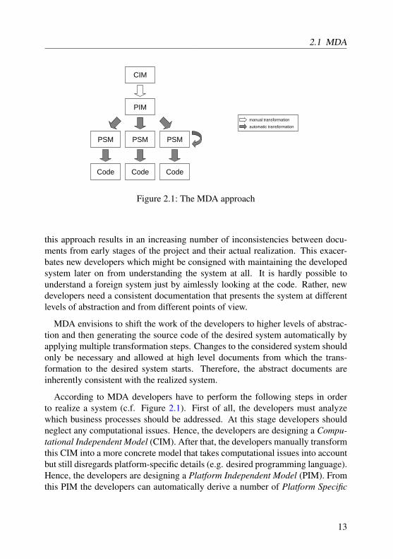
MDA envisions to shift the work of the developers to higher levels of abstrac-tion and then generating the source code of the desired system automatically byapplying multiple transformation steps. Changes to the considered system shouldonly be necessary and allowed at high level documents from which the trans-formation to the desired system starts. Therefore, the abstract documents areinherently consistent with the realized system.
According to MDA developers have to perform the following steps in orderto realize a system (c.f. Figure 2.1). First of all, the developers must analyzewhich business processes should be addressed. At this stage developers shouldneglect any computational issues. Hence, the developers are designing a Compu-tational Independent Model (CIM). After that, the developers manually transformthis CIM into a more concrete model that takes computational issues into accountbut still disregards platform-specific details (e.g. desired programming language).Hence, the developers are designing a Platform Independent Model (PIM). Fromthis PIM the developers can automatically derive a number of Platform Specific
13

2 Metamodeling
M0
M1
M2
Model
Metamodel
System
Meta-metamodel
PIM PSM
describe
describe
describe
describe
M3
Figure 2.2: OMG’s modeling layers
Models (PSM) by applying model transformations. The needed model transfor-mations must have been developed beforehand. The vision is that these transfor-mations are independent from the concrete system development project and canbe applied in other projects as well. Finally, the applied transformations result inthe desired system. Any changes to this system may only be done at PIM levelbut not at any PSM level or the resulting code.
2.2 MOF
In order to perform model transformations we must come up with a definition ofthe term model. In the literature there still are ongoing debates on this defini-tion. Throughout this work we adopt the definition given in [OMG03]. Generallyspeaking a model is an abstraction of something that exists in reality. Abstrac-tion means that a model omits details of the to be modeled entity that are notimportant from the viewpoint of the model designer. In order to perform compu-tations (e.g. analysis, transformations) on a model the model must be written in awell-defined language. A well-defined language has well-defined syntax and se-mantics. Furthermore, the language must be suitable for automated interpretationby a computer. Model transformation means that we take one model written in awell-defined language as input and produce a new model written in the same or acompletely different well-defined language as output.
14

2.2 MOF
InfrastructureLibrary::Core
Basic PrimitiveTypes Constructs<<import>> <<import>>
MOF
EMOF CMOF
<<import>> <<import>> <<import>> <<merge>><<merge>>
<<merge>>
Figure 2.3: Package structure of MOF
The concept for specifying a well-defined language which can be used to de-scribe models is called metamodeling. A metamodel itself is a model written in awell-defined language. The metamodel describes the language which in turn de-scribes the desired models. Figure 2.2 illustrates the modeling layer architectureas proposed by the OMG. At the lowest layer M0 (instance layer) resides the tobe modeled system. The PIM and PSMs which model the system according to theMDA approach at different levels of abstraction belong to the next higher layerM1 (model layer). Nowadays, these models are often expressed in the variousdiagram types provided by the Unified Modeling Language (UML). The UMLprovides diagram types for use case driven requirements engineering (e.g. UseCase diagrams), diagram types for the static structure of a system (e.g. class dia-grams), diagram types for expressing the behavior of a system (e.g. state charts,sequence diagrams), and so on. As stated above modeling languages themselvesare models which are defined at layer M2 (metamodel layer) of OMG’s layer ar-chitecture. Again, languages that can be used to define modeling languages suchas UML are models of the next higher layer M3 (metametamodel layer). At thislayer the OMG has defined the Meta Object Facility (MOF). In order to avoidfurther recursion in the layer architecture the OMG designed the MOF using it-self as its modeling language. The semantics of the MOF is given in plain text[OMG06a]. Furthermore, the MOF coincides with a restricted version of UMLclass diagrams. Therefore, the OMG factored out the common part of MOF and
15

2 Metamodeling
UML class diagrams into the UML infrastructure library [OMG07] which is thenreused and adapted in order to define MOF and UML class diagrams. Figure 2.3clarifies the relationship between MOF and the UML infrastructure library. TheUML infrastructure library contains a package Core which in turn contains thepackages Basic, PrimitiveTypes, and Constructs. The Core pack-age is imported by the MOF package in order to access the contained packages.The MOF package itself contains two packages EMOF and CMOF. The packageEMOF package contains a subset of MOF called Essential MOF (EMOF). EMOFis designed to correspond closely to facilities found in common object-orientedlanguages in order to allow easy tool development and integration. In contrastthe package CMOF contains the Complete MOF (CMOF). CMOF provides moresophisticated concepts than EMOF and is used to specify modeling languagessuch as UML. The package CMOF merges the packages EMOF and Core. In con-trast to an import which only allows to access elements contained in the importedpackage a merge means the following3. Extending a given package just by us-ing imports requires the user to manually create a new class in the new packagefor each class in the given package. Thereby, the user has to manually ensurethat each class in the new package inherits from the corresponding class of thegiven package. After that the user can add their intended extensions to the newpackage. In contrast the package merge relieves the user of the presented manualsteps. Conceptually, for each element in the merged package the merge creates acorresponding element in the merging package and relates them by a generaliza-tion. If the merging package declares a class which name matches the name ofa merged class the declared class just inherits from the original class. Therefore,the package CMOF contains all concepts from the EMOF and the Core package.From now on every time we talk about MOF we actually refer to CMOF.
The most important part of the metamodel of the (C)MOF is shown in Fig-ure 2.4. Basically, a MOF model consists of classes that can be related with eachother using associations. Furthermore, classes contain operations and properties.Properties can be either attributes or association ends. To put it simple classescan be regarded as types of model elements, whereas associations can be seenas relations (i.e., typed sets of links) between model elements. In contrast to theformer MOF 1.4 standard the current version 2.0 introduces more sophisticatedconcepts for modularization and generalization as depicted in Figure 2.5. Basi-
3Technically we rely on an out-dated semantics of merge. We are the opinion that the old semanticsis more useful and intended compared to the actual semantics described in the latest version of thestandard.
16

2.2 MOF
UML 2.0: Infrastructure - Final Adopted Specification 111
Notation
No additional notation.
11.3 Classes diagram
The Classes diagram of the Constructs package specifies the Association, Class, and Property constructs, and adds
features to the Classifier and Operation constructs.
Figure 73 - The Classes diagram of the Constructs package
StructuralFeature
[0..1][0..1]
Class
(from Basic)
Pro perty
(from Basic)
Relationship
[0..1]
[0..1]
Operation
Class
isAbstract : Boolean = false
*0..1
ownedOperation
*{ordered,
sub se ts featu re ,
subsets ownedMember}
c lass
0..1 {subsets rede finition Context,
subsets namespace,
subsets featuringClassifier}
*
superClass
* {re de fin es gen eral}
Classifi er
Property
isReadOnly : Boolean = false
isDerivedUnion : Boolean = false
*
redefinedProperty
* {subsets redefinedElement}
*
subsettedProperty
*
0..1
/opposite
0..1
*0..1
ownedAttribute
*{ordered,
subsets attribute,
sub se ts ownedMe mbe r}
class
0..1 {subsets namespace,
sub se ts featu ringCla ssifier,
sub se ts classifier}
*0..1
/attribute
*{subsets feature,
union}
classifier
0..1 {subsets redefinitionContext}
Type
Association
isDerived : Boolean = false2..*0..1
memberEnd
2..*{ordered,
subsets member}
associat ion
0..1
*0..1
ownedEnd
*{ordered,
sub sets mem berEnd ,
subsets feature,
subsets ownedMember}
+owningAssociation
0..1{subsets association,
subsets namespace,
sub sets featu ringCla ssi fier}
1..*
/endType
1..*{subsets relatedElement}
Figure 2.4: Cut-out of MOF’s metamodel taken from [OMG06a]
cally, a package contains packageable elements (e.g. classes, associations, andpackages). Since packages are namespaces they can import each other. Further-more, packages can be related to each other by package merges as introducedabove. For the complete MOF 2.0 metamodel and its semantics the reader is re-ferred to [OMG06a]. For a detailed comparison between MOF 1.4 and MOF 2.0the reader is referred to [Ame08].
Figure 2.6 gives an example for the application of OMG’s layered modelingarchitecture. At instance layer M0 there is an picture of the to be modeled system(i.e., an integrated circuit (IC)). At modeling layer M1 we see the logic symbol ofan AND gate at the left hand side and a schematic representation of the packageof the IC at the right hand side. Both elements can be used to model a certainaspect of the system. The definition of symbols and packages resides on the
17

2 Metamodeling
Package
(from Basic)
Di rectedRel ati onsh ip
Packageabl eE lementNamespace
PackageableElement
PackageMerge
Type
Package
*0..1
ownedMember
*{redefines ownedMember}
owningPackage
0..1
{subsets namespace}
*
0. .1
nestedPackage*
{subsets ownedMember}
nestingPackage
0. .1 {subsets namespace}
*1
pa ckageMerge
*
{su bsets own ed Elem ent }me rg ing Package
1 {subsets source,
subsets owner}
1
mergedPackage
1 {subsets target}
*0..1
/ownedType
*{subsets ownedMember}
package
0..1
{subsets namespace}
Figure 2.5: Package concepts of MOF taken from [OMG07]
M0
M1
M2
M3
Symbol Package
Class
Figure 2.6: Exemplary application of OMG’s layered modeling architecture
18

2.3 OCL
Personage:String
Licenseownsowner licenses1 0..* Person
age:StringLicenseowns
owner licenses1 0..*
inv: owner.age >= 18
a. b.
Figure 2.7: Exemplary metamodel a. without and b. with an OCL constraint
metamodeling layer M2. Both definitions rely on the concept of classes that isdefined at the metametamodeling layer M3 as provided by the MOF.
2.3 OCL
As stated above MOF can be used to write a metamodel that describes whichstructural requirements a model must satisfy in order to conform to the meta-model. Typically, there are further constraints a model should adhere to whichcannot reasonably be expressed using a graphical notation. In the metamodel fromFigure 2.7a. there is a class Person associated with a class (Driving-)License.Without further constraints every model that links a Person regardless of its agewith an arbitrary number of Licenses conforms to the metamodel. Typically, aPerson can only obtain a License if its age is at least 18 for instance. MOFitself provides no means for expressing this essential constraint at all. Therefore,the OMG complemented the MOF with the textual object constraint language(OCL) [OMG06b]. A typical OCL constraint is shown in Figure 2.7b. The con-straint states that all Persons that are associated with at least one Licensemust be at least 18 years old. To this end the constraint is evaluated in the givencontext of class License. For each License the owner is determined. Finally,the constraint tests whether the age of each owner is at least 18. If there is at leastone Person whose age is less than 18 that owns a License the constraint eval-uates to false otherwise to true. By design the OCL can only be evaluatedwithout any side effects, i.e. a constraint cannot modify a given model at all4.Among others OCL can be used to specify invariants, pre-, and postconditions.An invariant is attached to a Classifier. The invariant is of type booleanand is required to evaluate to true for each instance of the Classifier at any
4There are extensions to the OCL that allow for model modifications (e.g. the imperative OCLpackage from the QVT standard).
19

2 Metamodeling
moment of time. The OCL standard does not specify what happens if an invariantevaluates to false. A model which violates any invariant simply does not con-form to the underlying metamodel. A precondition is an boolean expressionthat is attached to an Operation. Preconditions must evaluate to true beforethe attached Operationsmay be executed. Correspondingly, a postcondition isa boolean expression attached to an Operation that must evaluate to trueafter the execution of the attached Operation. Again the standard does notspecify what happens when a pre- or postconditions ever evaluates to false.
The abstract syntax of OCL (i.e., the metamodel of OCL) is defined on theUML superstructure rather than the UML infrastructure. For supporting MOFOCL provides two packages BasicOCL and EssentialOCL. As the namesimply BasicOCL defines a subset of OCL that matches the Basic packageform the UML infrastructure whereas EssentialOCL complements the EMOFpackage. Therefore, EssentialOCL is in line with CMOF as well.
20
3 QVT
As we have motivated in the preceding chapter we aim at founding our ownapproach on actually existing OMG standards. The upcoming Query / View /Transformation (QVT) standard is OMG’s approach for model integration. QVTcomplements the already introduced metamodeling standards MOF and OCL. Inorder to increase the usability and acceptability of our own approach we aim atintegrating our approach with the QVT standard where reasonable by means ofsyntax and concepts.
We start by explaining the running example we want to use throughout thiswork. After that we introduce OMG’s initial Request of Proposals (RfP) whichasked for proposals for a model integration approach. Relying on the runningexample we then present the resulting QVT standard in detail. Finally, we discussshortcomings of the current QVT standard which we want to address and avoidin our own approach.
3.1 Running example
In 2005 the Model Transformation in Practice Workshop1 (MTiP) was collocatedwith the MoDELS conference2. This workshop has been organized by members ofthe QVT related community as well as by members of the (triple) graph grammarcommunity. The corresponding Call for Papers (CfP)3 asked the participants totackle the following task using their favorite model integration solution. The aimwas to compare the used approaches with each other. The same task is addressedby the upcoming QVT standard as the running example. Therefore, this task canbe regarded as an official benchmark for QVT related approaches.
The task deals with the integration of a class diagram with a database schema.In fact the task only requires the transformation of a given class diagram into
1http://sosym.dcs.kcl.ac.uk/events/mtip05/2http://www.cs.colostate.edu/models05/3http://sosym.dcs.kcl.ac.uk/events/mtip05/long_cfp.pdf
21

3 QVT
Package
name:String
Classifier
name:String
PrimitiveDataType Class
persistent:Boolean
Attribute
name:Stringprimary:Boolean
Association
name:String
parent 0..1
package 1
classifiers *
type
1
attributes
*
src trg1 1
assocs *
cd
Figure 3.1: Metamodel for class diagrams
a corresponding database schema and not vice versa. Nevertheless, we aim ataddressing all integration scenarios as motivated in Chapter 1. The CfP pro-vides MOF metamodels for simple class diagrams (c.f. Figure 3.1) and databaseschemas (c.f. Figure 3.2). For clarification purposes we have done some minorchanges to the provided metamodels.
Basically, a Package of a class diagram has a name and contains Clas-sifiers. A Classifier4 has a name and can be a PrimitiveData-Type or a Class. A Class owns an arbitrary number of Attributes.Classes can be marked as persistent in order to express whether the in-stances of a Class are made persistent by the corresponding database. Fur-thermore, each Class may be related to another Class which represents theparent by means of a generalization relationship. Finally, Classes may
4In UML Classifier would be marked as abstract. However, in MOF this concept does notexist.
22

3.1 Running example
Schema
name:String
Table
name:String
Column
name:Stringtype:String
schema 1
tables *
ds
FKeyfkeys
*reference
1
cols
1..*
pkeys 1..*cols 1..*
table 1
Figure 3.2: Metamodel for database schemas
be related to each other by Associations. Each Attribute has a name.Attributes can be marked as primary in order to express that the regardedAttribute should be used as a primary key in the corresponding database.Furthermore, an Attribute has a type which is a Classifier (i.e., aPrimitiveDataType or a Class). An Association is related to a source(scr) and a target (trg) Class. Each Association has a name. A separateOCL constraint provided by the CfP demands that each Class owns at least oneAttribute. Additionally, at least one of the owned Attributes must bemarked as primary.
23

3 QVT
(Database) Schemas (c.f. Figure 3.2) have a name and consist of Tables.Tables have names and consist of Columns. Furthermore, a Table maydesignate a subset of its Columns as primary keys (pkeys). Finally, a Tablehas an arbitrary number of foreign keys (fkeys). Columns simply have a nameand a type. Each FKey refers to another Table and designates a subset of theColumns of the Table that owns the FKey as foreign keys.
Besides the metamodels of the to be integrated models the CfP provides a num-ber of rules how to realize the intended integration:
R1. Persistent classes in a given class diagram should be transformed into acorresponding table in the database schema. The name of the table shouldmatch the name of the class.
R2. Persistent classes that inherit from another class should correspond to thesame table in the database schema to which the parent class corresponds to.
R3. Non-persistent classes should not be transformed at top-level.
R4. Attributes that have a primitive data type should be transformed into a col-umn. The name of the column should match the name of the attribute. Thetype of the column should match the type of the attribute.
R5. An attribute a whose type is a persistent class c should be transformed asfollows. For each primary key attribute of c the table that corresponds tothe class that owns a should have a column. The column should be namedname_transformed attr. Thereby, name denotes the name of c.The set of created columns should be marked as constituting a foreign key.The foreign key should refer to the table that corresponds to the persistentclass c.
R6. An attribute a whose type is a non-persistent class c should be transformedas follows. For each attribute of c whose type is a primitive type the ta-ble that corresponds to the class that owns a should have a column. Thecolumn should be named name_transformed attr. The type of thecolumn should match the type of a. For each attribute of c whose type iseither a persistent or a non-persistent class the preceding rules should applyrecursively.
Because of rule R2 the transformation from a given class diagram into a databaseschema and back into a new class diagram possibly looses information. The trans-formation cannot recreate an inheritance hierarchy for classes created from a sin-gle table without additional information or user interaction. Rather, for each table
24

3.2 Request For Proposal
in the database schema only one class will be created in the class diagram whichowns all attributes created from the columns of the table.
In order to clarify the rules and show a simple test case the CfP provides a to betransformed class diagram (c.f. Figure 3.1 and the corresponding database schema(c.f. Figure 3.2). The provided test case is too simple to test all rules. On the onehand the test case does not include an inheritance hierarchy. On the other hand noclass contains an attribute whose type is a non-persistent class which in turn hasan attribute whose type again is a non-persistent class. In order to test our ownapproach we will, therefore, transform the simple test case first and then comeup with a more sophisticated transformation example in order to demonstrate theapplication of the more complex rules.
3.2 Request For Proposal
In 2002 the OMG published a Request for Proposal (RFP) [OMG02] which "ad-dresses a technology neutral part of MOF and pertains to: 1. Queries on models.2. Views on metamodels. 3. Transformations of models." Whilst the first chap-ters of the RFP only provide general information on the OMG as well as on theprocess of evaluating and adopting proposals, chapter 5 and 6 describe generaland specific requirements which must be fulfilled by submissions to this RFP.
The general requirements are:
G1. Models used in a submission should be expressed using OMG’s modelinglanguages (e.g. UML, MOF).
G2. Any model written in such a language should be accompanied by a match-ing XMI representation.
G3. If a submission utilizes both PIMs and PSMs the submission should providemappings between the PIMs and the corresponding PSMs.
G4. A submission should provide all relevant assumptions and context informa-tion.
G5. Each submission must clarify which features are mandatory and which areoptionally for implementation purposes.
G6. Submissions are encouraged to reuse existing (OMG) standards rather thanintroducing entirely new models specifying already existing functionality.
25

3 QVT
G7. A submission should justify any modifications it requires to existing OMGspecifications. Moreover, a submission should aim at upward compatibilitywith existing standards.
G8. Submissions should address reusability issues by factoring out functionalitythat could be used in various contexts.
G9. Although submissions should reuse functionality from already existingspecifications the number of dependencies should be as small as possible.
G10. A submission should not constrain implementations more than necessary.
G11. Submissions should be compatible with ISO’s Reference Model of OpenDistributed Processing.
G12. Each submission should discuss whether it can be used in environmentsthat require security issues.
G13. Submissions should specify to which degree they provide internationaliza-tion support.
The mandatory specific requirements are:
M1. Each submission should provide a language for querying models in orderto filter model elements and to select model elements as source for trans-formations.
M2. Submissions should provide a language for specifying transformations thattransform a source model conforming to one metamodel into a target modelconforming to another (or the same) metamodel.
M3. Each submission should define the abstract syntax of its query, view, andtransformation languages as MOF 2.0 metamodels.
M4. The proposed transformation language of each submission should supportthe automatic transformation of a source into a target model.
M5. Furthermore, the regarded transformation language should provide meansto create views of metamodels.
M6. Submissions should support the incremental propagation of changes froma considered source into the corresponding target model.
M7. Each submission should assume that the metamodels of the regarded mod-els are defined using MOF 2.0.
26

3.2 Request For Proposal
Finally, the optional specific requirements are:
O1. Submissions may support transformation specifications that can be exe-cuted bidirectionally (i.e., source-to-target as well as target-to-source trans-formations).
O2. Submissions may calculate and utilize traceability information between el-ements of the source and elements of the target model.
O3. Submissions may provide means for reusing and extending generic trans-formation specifications.
O4. Submissions may provide transactional mechanisms (i.e., commit and roll-back) for (part of) transformations.
O5. Submissions may support the consideration of external data that residesneither in the source nor in the target model.
O6. Submissions may support the transformations in the case that source andtarget model coincide (i.e., in-place transformations).
We aim at designing our own approach in a such a way that the result couldhave been a promising submission to OMG’s RFP. Actually, when we started de-signing our approach the deadline for submissions to the QVT-RFP was alreadydue. Nevertheless, we want to regard as many requirements of the RFP as pos-sible. As the current QVT standard which we will introduce later in this chaptersuffers from a number of shortcomings our approach can be seen as a proposal ofhow to deal with some of these shortcomings.
Particularly, our approach considers the requirements as follows. RegardingRequirement G1 it is unclear what is meant with model. In accordance withRequirements M3 and M7 we present the metamodel of our model integrationapproach as a MOF 2.0 metamodel and assume that the to be integrated mod-els themselves conform to MOF 2.0 metamodels. Concerning Requirement G2we rely on the Java Metadata Interface (JMI) standard [Sun02] for implementa-tion purposes. This standard provides XMI readers and writers for a given MOFmetamodel. Thereby, XMI is XML-based textual representation destined for theserialization of models. Requirements G3 does not apply to our approach. Nat-urally, we want to adhere to Requirement G4 as far as possible. Nevertheless,this work is not a complete technical reference. As we do not distinguish be-tween mandatory and optional features of our approach Requirement G5 doesnot apply to our approach. Regarding Requirement G6 we state that we plan
27

3 QVT
to adopt a number of convenient and user-friendly features of the current QVTstandard. However, we intentionally do not found our approach directly on theQVT standard. On the one hand we want to get rid of the shortcomings of theQVT standard. On the other hand our approach relies on a formal foundation thatdoes not reside in OMG’s world of metamodeling, yet. As we do not modify anyexisting OMG specifications Requirement G7 does not apply to our approach.Furthermore, we do not aim at regarding Requirement G8. Requirements G9 andG10 are too generic for proving adherence to them. Requirements G11, G12, andG13 are just out of scope for our approach.
Regarding Requirements M1 and M2 we state that the left-hand sides of ourTGG rules which we will introduce later on in detail constitute the query partwhile the right-hand sides constitute the transformation part of our model inte-gration language. As (semi-)automatic model integration support is one of thekey goals of our approach we strongly want to adhere to Requirement M4. Con-cerning Requirement M5 we admit that our approach does not aim at dedicatedview creation support. Nevertheless, in Section 11.1 we comment on this issue.Surprisingly, the current QVT standard intentionally disregards views as well. Inaccordance to Requirement M6 our approach aims at the incremental propagationof model changes. As we will point out in Chapter 8 our current implementationof our approach does not yet support incremental updates.
Since we aim at a declarative model integration approach we want to adhere toRequirement O1. As the maintenance of traceability information is another keygoal of our approach we also want to adhere to Requirement O2. Furthermore, wewant to incorporate means for reuse and extensibility in accordance to Require-ment O3. We do not consider Requirement O4 in this work. We do not want toallow for any external data as proposed in Requirement O5. Finally, we do notsupport in-place transformations as proposed in Requirement O6. For in-placetransformations we rely on graph transformations as introduced in Chapter 4 as amore appropriate approach for this purpose.
3.3 Specification
There have been a number of submissions to OMG’s QVT-RFP from variousgroups with partners from companies (e.g. IBM, Sun) as well as from univer-sities (e.g. Kings College London, University of Paris VI, University of New
28

3.3 Specification
MOF
EMOF
OCL
EssentialOCL
QVT
QVTBase QVTTemplate
QVTCore QVTRelational QVTOperational
ImperativeOCL
<<import>> <<import>> <<import>>
<<import>>
<<import>> <<import>>
<<import>> <<import>> <<import>>
<<import>>
<<import>>
<<import>> <<import>>
<<import>>
Figure 3.3: Package structure of QVT
York). Meantime, the OMG has adopted a specification which currently is underfinalization.
The specification states that it depends on OMG’s MOF 2.0 and OCL 2.0 stan-dards. Figure 3.3 illustrates these dependencies. The specification defines three(sub-)languages called Relational, Core, and Operational. The Relational andthe Core languages allow for the declarative specification of queries and trans-formations, whereas the Operational language provides an imperative approach.Declarative means that the specification describes desirable situations (i.e., bothregarded models are consistent with each other) but does not state how to reachthese situations. In contrast an imperative specification explicitly provides oper-ations that can be invoked in order to keep two regarded models consistent witheach other.
29
3 QVT
The Relational language aims at user-friendliness and supports complex objectpattern matchings. Traceability links between model elements are maintainedimplicitly. The Relational language provides a graphical and a textual concretesyntax. In contrast, the Core language is defined using minimal extensions toEMOF and OCL. Traceability links are explicitly specified, maintained, and dealtwith as any other model element. There is only a textual concrete syntax avail-able for the Core language. Since the Core language is quite simple its semanticscan be defined quite easily. The semantics of the Relational language is given bya transformation that transforms a given Relational specification into a semanti-cally equivalent Core specification. The Relational and the Core languages areequally powerful. As already mentioned above the Operational language realizesan imperative approach. Therefore, the Operational language rather matches oper-ational graph grammar-based approaches than declarative triple graph grammar-based approaches. Thus, we disregard the Operational language for the remainderof this work. Nevertheless, we should mention that QVT provides an extensionto OCL called imperative OCL which is used by the Operational language. Incontrast to OCL which only supports side-effect free model queries imperativeOCL provides functionality to intentionally modify models.
3.3.1 Basic concepts
The QVTBase package (c.f. Figure 3.4) contains the basic concepts of QVT whichare used throughout the definition of the three sublanguages. The central constructof QVT is called Transformation. A transformation describes how to transforma set of typed models into another. To this end a transformation contains a num-ber of rules. At runtime a transformation is executed in a certain direction whichspecifies which models are considered as source and which model is consideredas target of the transformation. A typed model as an input of a transformation isa model that conforms to a metamodel written in EMOF. A rule specifies howmodel elements of typed models are related with each other. To this end eachrule contains a number of domains. A domain specifies which elements of atyped model are regarded by the corresponding rule. A domain can be markedas checkable or enforceable. For domains that are marked as checkable the con-taining rule must check whether the model elements specified by the domainsexist and report missing elements. In contrast a rule must ensure the existenceof all model elements of domains that are marked as enforceable by modifyingthe corresponding typed model appropriately. Furthermore, the QVTBase pack-
30

3.3 Specification
NamedElement(from EMOF)
Class(from EMOF)
Package(from EMOF)
Tag(from EM OF)
TypedModel
1..*
*
+usedPa cka ge1..*
+typedModel
*
* *+dep endsOn
*+depende nt
*
Transformation
*
1
+modelParameter*
{ordered}
+transformation
1
*
0..1
+ownedTag*
+transformation
0..1
*0..1
+extendedBy *+extends
0..1
DomainisCheckable : BooleanisEnforceable : Boolean
1
*+typedModel
1
+domai n *
Rule
*
1
+rule
*
+tran sforma ti on
1*
1
+domai n *+rule 1
0..1
*
+overrides0..1
+overriden*
Figure 3.4: QVTBase package taken from [OMG05b]
Operation(f rom EMOF)
Element(from EMOF)
Function
OclExpression(from EssentialOCL)
0 ..1
0..1
+queryExpression
0 ..1
+function
0..1
Predicate
1
0 ..1
+co nditi onExpression
1
+predicate
0 ..1
Variable(from EssentialOCL)
Pat tern
*
1
+predicate*
+pattern
1
*
0..1
+bindsTo*
+p attern0..1
Parameter(from EMOF)
FunctionParameter
Function owns FunctionParameterthrough Operation owning Parameter in EMOF
Figure 3.5: QVTBase package taken from [OMG05b] (cont.)
31

3 QVT
LiteralExp(from EssentialOCL)
Element(from EMOF)
Class(from EMOF)
Property(from EMOF)
ObjectTemplateExp
1
*
+referredClass
1
+objectTemplateExp
*
Variable(from EssentialOCL)
PropertyTemplateItem
1
*+referredProperty1
+p ropertyItem
*
*
1
+part *
+objContainer 1
TemplateExp
0..1
0..1
+bindsTo0..1
+templateExp0..1
CollectionType(from EssentialOCL)
OclExpression(f rom Esse ntial OCL)
1
0..1
+value
1
+propertyItem
0..1
0..1
0..1
+where 0..1
+owner0..1
CollectionTemplateExpkind : CollectionKind
0..1
*
+referre dColle ct ionType0..1
+col le ction Templ ateExp
*
0..1
*
+listContainer
0..1
+part*0..1
0..1
+match
0..1
+matchingExp
0..1
Figure 3.6: QVTTemplate package taken from [OMG05b]
age (c.f. Figure 3.5) introduces the concept of patterns. A Pattern declares anumber of variables which are to be bound by matching the pattern in a typedmodel. Patterns may have predicates that are boolean expressions that constrainthe matching of a pattern in a typed model. Besides patterns transformations ownfunctions. A function is an operation which is free from any side-effects (i.e.,a function may not perform any modifications). Therefore, functions representqueries. Each function may be provided with a number of function parameters.
The QVTTemplate package (c.f. Figure 3.6) basically introduces the conceptof template expressions. A template expression matches one (object template ex-pression) or multiple (collection template expression) elements in a typed model.A template expression only matches if the attached where expression holds aswell. A template expression may have a number of property template items. Aproperty template item specifies constraints on the values of attributes of the re-garded model elements.
32

3.3 Specification
1.. *
Rule(from QVTBase)
Domain(from QVTBase)
Element(from EMOF)
Operation(from EMOF)
TypedModel(from QVTBase)
Class(f rom EMOF)
Property(f ro m EMOF)
Key
1
*
+ide nt if ie s1
+key*
1.. *
*
+part
+key*
TemplateExp(from QVTTemplate)
DomainPattern
0..1
1
+templateExpression
0..1
+d omainPatte rn1
RelationDomain
1
1
+pat te rn1
+relationDomain
1
RelationImplementation
1
*
+impl1
+re la ti onImplementatio n*
1
*
+inDirectionOf
1
+relationImplementation*
Pattern(f ro m QVTBa se)
Variable(from EssentialOCL)
1
0..1
+rootVariable1
+relatio nDomain
0..1
Relation/ isTopLevel : Boolean
*
0..1
+operationalImpl*
+rela ti on0..1
0 ..10..1+where
0 ..1+when Owner
0..1
0..10..1+when
0..1
+whereOwn er
0..1
*
0..1
+variable*
+relati on
0..1
Figure 3.7: QVTRelation package taken from [OMG05b]
3.3.2 The Relational language
The QVTRelation package (c.f. Figure 3.7 incorporates the concepts from theQVTBase and the QVTTemplate packages and provides specializations for them.The basic concept of the Relational language is a relation. A relation is a spe-cialization of a rule. Each relation declaratively specifies which model elementsrelate to which model elements. To this end a relation declares at least two rela-tion domains, a when- and a where-pattern. A relation domain is a specializationof a domain. Each relation domain is provided with a domain pattern which is aspecialization of a pattern and is to be matched in the corresponding typed model.Furthermore, each relation domain has a distinguished variable that is called rootvariable. The when-pattern of a relation acts like a precondition for the relation.That means that the relation must only hold for situations when the when-patternholds as well. In contrast the where-pattern is required to hold when the rela-tion holds. That means that a relation can invoke other relations using where-
33

3 QVT
patterns. A relation that is not invoked by any other relation is called a top-levelrelation. Since all non-top-level relations are directly or indirectly invoked bytop-level relations all models are consistent when all top-level relations hold. Be-sides the declarative specification each relation may be provided with a relationimplementation. A relation implementation is a black-box implementation whichoperationally enforces the corresponding relation when the relation does not hold.Finally, the QVTRelation package introduces the concept of keys. A key is a setof attributes of a class that uniquely identify instances of that class. Keys are usedwhen a transformation is executed in enforcement mode. Basically, there are twopossibilities how to enforce consistency when the target model violates relations.On the one hand the transformation can delete all inconsistent model elements andcreate consistent ones instead. On the other hand the transformation can modifythe inconsistent model elements appropriately. In order to determine which repairaction should be taken keys are used in order to identify model elements that canbe modified instead of being deleted and recreated.
Regarding our running example of integrating a class diagram with a corre-sponding database schema the declaration of a transformation in QVT Relationallooks as follows:
transformation cdds_integration(cd:cd_metamodel,db:db_metamodel} {
The declared transformation is called cdds_integration. The tranformationcan be invoked on two models, one of which conforms to the cd_metamodelmetamodel while the other conforms to the cd_metamodel metamodel.
For instance the declaration of a relation looks as follows:
relation PackageToSchema {domain cd p:Package { name = pn }domain db s:Schema { name = pn }
}
The name of this relation is PackageToSchema. The relation declares twodomains p of type Package from the cd_metamodel metamodel and s oftype Schema from the db_metamodel metamodel. Additionally, there is athird variable pn. This variable implicitly expresses that the name of p should
34

3.3 Specification
p:Packagename=pn
s:Schemaname=pn
<<domain>> <<domain>>
cd db
a) PackageToSchema
b) ClassToTablewhenPackageToSchema(p, s)
whereAttributeToColum(c, t)
c:Class t:Table
cd db
c) AttributeToColumn
a:Attributename=an
col:Columnname=an
<<domain>> <<domain>>
p:Package s:Schema
cd db
c:Classname=cn
t:Tablename=cn
<<domain>> <<domain>>
Figure 3.8: Examples of QVT’s graphical syntax
match the name of s. Figure 3.8a illustrates this relation using the graphicalsyntax of QVT.
If the transformation cdds_integration is invoked in order to check twomodels for consistency for each Package p there must be a Schema s suchthat the name of s matches the name of p and vice versa. Otherwise, bothmodels are not consistent with each other.
If the transformation cdds_integration is invoked in order to enforceconsistency of two models one model must be designated as the source and the
35

3 QVT
other as the target model beforehand. Let us assume that cd refers to the sourceand db refers to the target model. If there exists a Package p in cd such thatthere is no Schema s with a matching name in db the Transformationwill modify db in order to enforce consistency. To this end the transformationeither can change the name of an existing Schema or the Transformationcan create a new Schema with the matching name. In order to select one ofthese possibilities the Relation language provides the key construct which willbe described later on. Finally, if there is a Schema s which name does notmatch the name of any Package p the transformation deletes s.
Let us now look at the declaration of a second relation ClassToTable:
relation ClassToTable {domain cd c:Class { namespace = p,
name = cn }domain db t:Table { schema = s,
name = cn }
when {PackageToSchema(p, s);
}
where {AttributeToColumn(c, t);
}}
The graphical syntax of this relation is shown in Figure 3.8b. Similar to relationPackageToSchema this relation demands that for each Class c in cd thereshould be a Table t in db such that the name of t matches the name of s andvice versa. Additionally, the when-clause states that the name of t must onlymatch the name of c if the namespace p of c relates to the schema s of t.Finally, the where-clause states that if c relates to t then the Attributes ofc must relate to the Columns of t according to the following relation:
relation AttributeToColumn {domain cd a:Attribute { class = c,
name = an }
36

3.3 Specification
domain db col:Column { table = t,name = an }
}
Figure 3.8 depicts this relation in QVT’s graphical syntax.
Finally, the declaration of keys looks as follows:
transformation cdds_integration(cd:cd_metamodel,db:db_metamodel} {
key Table(name, schema);key Column(name, owner);...
}
That means that the relation ClassToTable will create a new Table when thetransformation is executed in enforcemode and a Tablewith matching nameand schema does not already exist. Accordingly, a new Column will only beadded if there is no Column with matching name and owner.
Expressions used in relations must adhere to the following restrictions in orderto guarantee the executability of a transformation. Arbitrary expressions wouldrequire a sophisticated constraint solver which is hard to implement. Therefore, itmust be possible to rearrange expressions in the when-clause, the where-clause,and the source domains such that:
1. object.property = variablewhere variable is an unbound variable and object is a variable thatalready has been bound to an object beforehand.
2. object.property = expressionwhere object has already been bound to an object beforehand and ex-pression does not contain any unbound variables.
3. There are no further expressions that contain unbound variables.
Furthermore, for the target domain holds that:
4. object.property = expressionwhere object has already been bound to an object beforehand and ex-pression does not contain any unbound variables.
5. There are no further expressions that contain unbound variables.
37

3 QVT
Pattern(from QVTBase)
CoreDomain
CorePattern
Mapping
*
*
+specification*
+refinement*
*
0..1
+local *
+co nte xt
0..1
GuardPattern
BottomPattern
Area
1
1
+guardPattern1
+area
1
1
1
+bot tomPatte rn
1
+area1
Domain(from QVTBase)
Rule(f ro m QVTBase)
*1+domain
*+rule1
Figure 3.9: QVTCore package taken from [OMG05b]
3.3.3 The Core language
As already mentioned above the Core language in contrast to the Relational lan-guage which aims at user-friendliness is simpler and more technical. The basicconcept of the Core language is called mapping (c.f. Figure 3.9). A mapping is aspecialization of a QVT rule. Each mapping consists of a middle area and an arbi-trary number of core domains. An area consists of a guard and a bottom pattern.A guard pattern is a pattern which is to be matched in a typed model. Thereby,the matching of a guard pattern provides a binding for the variables of the patternwithout modifying the typed model. A bottom pattern is only matched when itscorresponding guard pattern has been successfully matched. The bottom patternmay use variables which already have been bound by the matching of the guardpattern. In contrast to the guard pattern a bottom pattern may modify the under-lying typed model. A core domain is an area that is assigned to a certain typedmodel. Since core domains inherit from domains they can be marked as checkableor enforceable as explained above. As Figure 3.10 shows bottom patterns consistof an arbitrary number of realized variables, assignments, and enforcement opera-tions. Realized variables can be used in order to create or delete model elements.Assignments are used to modify attribute values of matched model elements. An
38

3.3 Specification
Variable(from EssentialOCL)EnforcementMode
CreationDeletion
<<enumerat ion>>
Property(from EMOF)
OclExpression(from EssentialOCL)
RealizedVariable
AssignmentisDefault : Boolean
1
*
+targe tPrope rty
1
+assignm ent*
10..1 +slotExpression1
+sl otAssignment
0..1
10..1 +value 1
+valueAssignment
0..1
BottomPattern
*
1
+realizedVariable*
+bottomPattern
1
*
1
+assignm ent*
+bottomPattern
1
OperationCallExp(f rom Essenti al OCL)
EnforcementOperationenforcementMode : EnforcementMode*0..1
+enforcementOperation
*+bottomPattern0..1
1
*
+operationCallExp1
+enforcementOperation
*
Figure 3.10: QVTCore package taken from [OMG05b] (cont.)
enforcement operation is invoked in a certain enforcement mode (i.e., creation ordeletion mode). In creation mode the enforcement operation is supposed to createnew model elements in order to recover model consistency. Whereas, in deletionmodel the enforcement operation is supposed to delete model elements.
Figure 3.11 clarifies the decomposition of a mapping into areas and patterns.Domain L contains the patterns to be matched in one model. Domain R containsthe patterns to be matched in a second model. Middle Area contains the patternsto be matched in the mapping model. To recall in the Core language correspon-dence links are explicitly dealt with in an own model. The guard patterns haveto be matched in their corresponding model in order to allow for the matching of
39
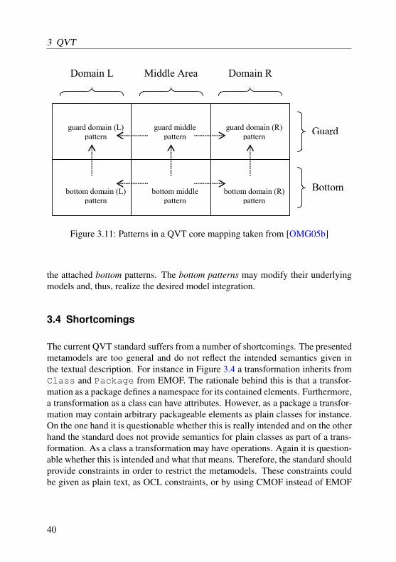
3 QVT
Guard
Bottom
Domain R Domain L Middle Area
guard domain (L) pattern
bottom domain (L) pattern
bottom middle pattern
bottom domain (R) pattern
guard middle pattern
guard domain (R) pattern
Figure 3.11: Patterns in a QVT core mapping taken from [OMG05b]
the attached bottom patterns. The bottom patterns may modify their underlyingmodels and, thus, realize the desired model integration.
3.4 Shortcomings
The current QVT standard suffers from a number of shortcomings. The presentedmetamodels are too general and do not reflect the intended semantics given inthe textual description. For instance in Figure 3.4 a transformation inherits fromClass and Package from EMOF. The rationale behind this is that a transfor-mation as a package defines a namespace for its contained elements. Furthermore,a transformation as a class can have attributes. However, as a package a transfor-mation may contain arbitrary packageable elements as plain classes for instance.On the one hand it is questionable whether this is really intended and on the otherhand the standard does not provide semantics for plain classes as part of a trans-formation. As a class a transformation may have operations. Again it is question-able whether this is intended and what that means. Therefore, the standard shouldprovide constraints in order to restrict the metamodels. These constraints couldbe given as plain text, as OCL constraints, or by using CMOF instead of EMOF
40

3.4 Shortcomings
FunctionParameter
ParameterOperation
Function
operation ownedParameter
FunctionParameter
ParameterOperation
Function
operation ownedParameter
function{redefines operation}
ownedFunctionParameter{redefines ownedParameter}
a.
b.
Figure 3.12: Part of QVT’s metamodel a. incomplete, b. completed
which provides concepts as subset or redefines. Figure 3.12 illustrates this. Fig-ure 3.12a. represents a situation from Figure 3.5. The standard says that "Functionowns FunctionParameter through Operation owning Parameter in EMOF". How-ever, the preented metamodel does not reflect this. Since Function inheritsfrom Operation a function owns parameter. Since FunctionParameterinherits from Parameter a function can have function parameter besides anyother parameters. Furthermore, since an operation owns parameters function pa-rameters may be attached to arbitrary operations. This is not what is intended.Using the concept of redefines from CMOF the fixed metamodel looks as de-picted in Figure 3.12b. The redefinitions ensure that a function can only haveparameters that are function parameters. The other way round a function param-eter can only be attached to a function. The drawback of this solution is that itrequires the QVT standard to use the more complex CMOF rather than EMOF forits definition. Another solution is to use the following OCL constraints:
context Functioninv: ownedParameter->forAll( p |
p.oclIsKindOf( FunctionParameter ))
41

3 QVT
context FunctionParameterinv: operation.oclIsKindOf( Function )
The first constraint concerns class Function. The constraint states that allownedParameters of Function in fact are FunctionParameters. Cor-respondingly, the second constraint concerning FunctionParameters en-sures that the Operation a FunctionParameter is attached to in fact isa Function. The advantage of these constraints is that they do not require QVTto switch to CMOF. The disadvantage is that textual constraints are less elegantthan using redefines from CMOF. Furthermore, the usage of redefines improvesthe readability of the metamodels. For instance Figure 3.12b explicitly depictsthe relationship of Functions and FunctionParameters. In contrast inFigure 3.5 this relationship is only implicitly given and not depicted. This exac-erbates the understandability of QVT’s metamodel.
Another issue is the application of the checkonly and enforce concept. TheQVT standard states that domains can be marked as checkonly or enforce. How-ever, the standard does not require a domain to be marked. Furthermore, thestandard does not describe in which way a domain that is not marked is dealt with(e.g. by defining a default value). On the one hand it would be reasonable toregard checkonly as default. A transformation may not modify models by match-ing domains marked as checkonly and, therefore, cannot accidentally corrupt theregarded models. On the other hand it would be reasonable to regard enforce asdefault since usually transformations are intended to modify models. Regardlesswhich alternative is preferable the QVT standard should specify a default. Other-wise two standard-compliant implementations might treat a given transformationdifferently. Another solution is to make the marking of domains as checkonly orenforce mandatory.
Furthermore, it is questionable whether it is necessary to specify checkonlyand enforce at the fine-grained level of rules rather than on the level of trans-formations. Certainly, the specification at rule level is more flexible and moreexpressive. Nevertheless, it exacerbates the understandability of a transformationas a whole since some rules might modify the underlying models whilst otherrules only perform checks in enforcement mode. Altogether, practice must provewhether the specification of checkonly and enforce is really required at a fine-grained level.
42

3.4 Shortcomings
The key concept introduced by the QVT standard suffers from the followingfact. The definition of keys by the specificator of a transformation requires themto know which sets of attributes of a certain class in a given metamodel constitutekeys. Since the specificator of a transformation might differ from the specificatorof the considered metamodel the definition of keys in fact should be included inthe metamodel. Unfortunately, MOF does not provide support for the definitionof keys. Although (OCL) constraints can be used to ensure that sets of attributesadhere to the requirements for keys (i.e., the values of attributes that constitutea key uniquely identify an instance of the corresponding class) this informationcannot be externally accessed by the specificator of a transformation. Therefore,keys defined by the specificator of a transformation might violate the require-ments of keys resulting in erroneous transformations. Thus, the concept of keysintroduced by the QVT standard is merely an unsatisfactory crutch. Since keysare useful not only for model transformation purposes MOF need to be extendedby an adequate key concept.
Finally, in our opinion the restrictions the QVT standard puts on expressionsused in rule patterns are too strong at conceptual level. Admittedly, less restric-tions might make it difficult to implement the standard and requires the use ofa powerful constraint solving mechanism in general. Nevertheless, implementa-tional issues should not affect the standard at conceptual level. Furthermore, theQVT standard says that "It should be possible to organize the expressions that oc-cur in the target domain, into a sequential order that contains only the followingkinds of expressions: ...". This statement implies a certain direction of the desiredmodel transformation. However, in the context of declarative QVT specificationsthe direction of transformation will be chosen at runtime not at specification time.Therefore, the statement undesirably requires the specificator to virtually interprettheir declarative specification in mind at specification time.
Being aware of the identified shortcomings of QVT we aim at appropriatelyaddressing them in our approach. First of all, we specify the metamodel of ourapproach by utilizing the CMOF standard rather than EMOF. By doing so we canrely on the concepts of subsets and redefines for conveniently specifying a morecorrect and complete metamodel.
Furthermore, we initially do not adopt the concepts of checkonly and enforcefrom the QVT standard. As we will see later we derive operational rules fromdeclarative rules, which will never modify the source and the target model atthe same time. Rather, model transformation will be executed in a certain user-controlled direction. In our approach checkonly and enforce could be used in order
43

3 QVT
to restrict the set of to be derived operational rules. As the rule derivation will beperformed automatically it is questionable whether restricting the set of derivedrule is really useful in practice. Definitely, we are convinced that checkonly andenforce should not be used at the fine-grained level of rules.
Regarding the key concept as proposed by the QVT standard, we think thatsuch a key concept should be defined by the MOF standard rather than by anymodel integration approach. As we will see later our approach distinguishes ele-ments that are to be created from elements that already exist. Furthermore, our ap-proach provides detailed context information that enables us to uniquely identifyan element. Thus, we do not really need a key concept. Therefore, we considerthe definition of an own key concept as out of scope for our work.
Finally, at conceptual level we will not put any restrictions on expressions usedin rule patterns. However, our implementation will not incorporate the neededsophisticated constraint solving mechanism and, thus, will only be able to dealwith a restricted subset of possible expressions.
44
4 Graph Grammars
In this chapter we present the basics of graph grammars as far as they concernour approach. On the one hand graph grammars constitute the formal foundationof triple graph grammars in general and our approach in particular. On the otherhand from each declarative triple graph grammar rule a number of operationalgraph grammar rules is derived (cf. Chapter 7) which can be applied in order torealize the desired model integration. Furthermore, for code generation purposeswe rely on a meta-case tool that is able to generate Java code from graph grammarrules (cf. Chapter 8). Therefore, graph grammars can be regarded as intermediatecode between the declarative triple graph grammar specification and executable(Java) code.
We start by briefly giving an introduction to graph grammars. After that weexplain basic and more sophisticated elements of graph grammars and informallyexplain their semantics. Finally, this chapter concludes by introducing the idea ofpair and triple graph grammars on which our work relies on.
4.1 String grammars
Graph grammars have been introduced in the late sixties by Pfaltz, Rosenfeld[PR69] as an extension to string grammars. String grammars are a well-knownconcept and are widely used for the specification of textual (programming) lan-guages (e.g. the Java language). A language is a (usually indefinite) set of sen-tences (e.g. syntactically correct Java programs). Each sentence is made from agiven set of words (e.g. reserved Java words, identifiers, etc.). A grammar con-sists of a set of rules (e.g. written in BNF) that describe in which way words canbe combined in order to make sentences that belong to the regarded language.
The following example taken from the Java language specification [GJSB05]specifies the language of decimal numbers that are allowed in Java.
45

4 Graph Grammars
DecimalNumeral ::= 0 | NonZeroDigit Digits
Digits ::= ε | Digit | Digits Digit
Digit ::= 0 | NonZeroDigit
NonZeroDigit ::= 1 | 2 | 3 | 4 | 5 | 6 | 7 | 8 | 9
The first rule states that a DecimalNumeral either is a 0 or a sequence of NonZe-roDigit Digits. The second rule specifies that Digits are either the empty word,a digit, or a sequence of Digits Digit. A Digit is either a 0 or a NonZeroDigit.Finally, a NonZeroDigit is either 1, 2, 3, 4, 5, 6, 7, 8, or 9. DecimalNumeral,NonZeroDigits, Digits, and Digit are called nonterminal symbols. Nonterminalsymbols have to be resolved by the application of further rules. In contrast 0, 1,2, 3, 4, 5, 6, 7, 8, and 9 are called terminal symbols which cannot be resolvedany further. According to this grammar the sentence 6563 is an element of thespecified language while 06563 is not.
Basically, string grammars suffer from the following flaws. Firstly, string gram-mars are restricted to textual languages. Secondly, string grammars can only spec-ify one dimensional languages. The first flaw merely is a matter of taste whethera graphical representation is more comprehensible, more compact, more suitablefor a certain task, or anything else than a textual representation. The second flawis a matter of expressiveness. Both flaws are addressed by graph grammars whichin turn come with their own flaws.
4.2 Graph schemas
Similar to a string grammar a graph grammar specifies a language (i.e., a set ofgraphs). In the literature there are various definitions of the term graph. In thecontext of this work a graph consists of a set of nodes (or vertices) and a set ofedges. Each node and each edge is typed. Each node may carry a number ofattributes according to its type. Each edge links two nodes with each other. Thetype of an edge specifies nodes of which types may be linked by the edge. For aformal definition of graphs the reader is referred to [Sch91]. The types of nodesand edges are specified in a graph schema. A graph must conform to the graphschema in order to be an element of the regarded language. Figure 4.1a. depicts
46
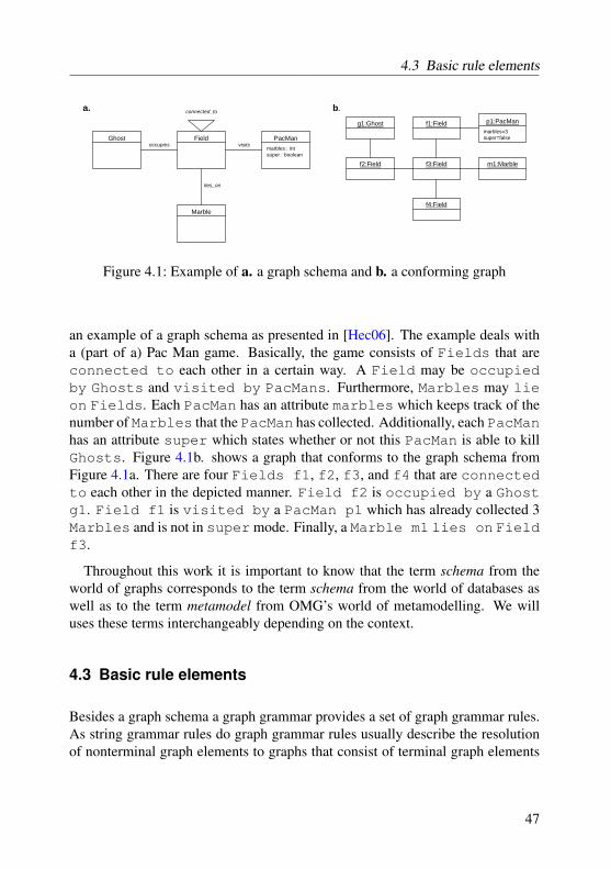
4.3 Basic rule elements
Ghost Field PacMan
Marble
marbles : intsuper : boolean
occupies visits
lies_on
a. b.
f1:Field
f3:Field
f4:Field
f2:Field
g1:Ghost
m1:Marble
p1:PacManmarbles=3super=false
connected_to
Figure 4.1: Example of a. a graph schema and b. a conforming graph
an example of a graph schema as presented in [Hec06]. The example deals witha (part of a) Pac Man game. Basically, the game consists of Fields that areconnected to each other in a certain way. A Field may be occupiedby Ghosts and visited by PacMans. Furthermore, Marbles may lieon Fields. Each PacMan has an attribute marbles which keeps track of thenumber of Marbles that the PacMan has collected. Additionally, each PacManhas an attribute super which states whether or not this PacMan is able to killGhosts. Figure 4.1b. shows a graph that conforms to the graph schema fromFigure 4.1a. There are four Fields f1, f2, f3, and f4 that are connectedto each other in the depicted manner. Field f2 is occupied by a Ghostg1. Field f1 is visited by a PacMan p1 which has already collected 3Marbles and is not in super mode. Finally, a Marble m1 lies on Fieldf3.
Throughout this work it is important to know that the term schema from theworld of graphs corresponds to the term schema from the world of databases aswell as to the term metamodel from OMG’s world of metamodelling. We willuses these terms interchangeably depending on the context.
4.3 Basic rule elements
Besides a graph schema a graph grammar provides a set of graph grammar rules.As string grammar rules do graph grammar rules usually describe the resolutionof nonterminal graph elements to graphs that consist of terminal graph elements
47

4 Graph Grammars
a.
fa:Field
fb:Field p:PacMan
g:Ghost fa
fb g
::=
fa:Field fa m:Marble::=
b.
fa:Field m:Marble
<<create>>
<<create>>
fa:Field
fb:Field p:PacMan
g:Ghost
<<create>>
<<destroy>>
<<destroy>>
<<destroy>>
createMarblecreateMarble
killPacMan killPacMan
Figure 4.2: Example of a. normal graph rules and b. collapsed rules
only. Similar to string grammars that have a particular nonterminal symbol calledstart symbol from which the construction starts, graph grammars have a particularrule called axiom that will be executed exactly one time at the beginning.
In contrast graph rewriting (transformation) systems provide a set of graphrewriting rules. A graph rewriting system does not consider nonterminal sym-bols. Rather, graph rewriting rules describe the replacement of (terminal) graphpatterns with other (terminal) graph patterns. To be honest we rely on graphrewriting systems rather than on real graph grammars as we are not dealing withnonterminal graph elements.
A graph rewriting rule consists of a left-hand side and a right-hand side. Inorder to apply the rule on a regarded graph a part of the graph is identified whichmatches the pattern of the left-hand side of the rule. If such a match cannot befound the rule cannot be applied. If more than one match is found the rule usuallyis nondeterministically applied to one of the possible matches. Finally, the chosenmatch is rewritten by the right-hand side of the rule.
Actually, a graph rewriting rule has a third part that denotes graph elementsthat are kept rather than rewritten. In common approaches (e.g. [Sch91]) thisthird part is implicitly given rather than explicitly specified. Furthermore, in someapproaches (e.g. [Zün01]) left-hand side and right-hand side are written in a col-lapsed manner in which both sides are concurrently depicted in the same diagram.
Figure 4.2a. gives examples of graph rewriting rules. The first rule demon-strates the matching of an element as well as the creation of new elements. Inorder to apply rule createMarble to the graph of Figure 4.1b. the left hand
48

4.4 Sophisticated rule elements
side of the rule must be matched. The rule demands to match an element of typeField. There are four possible matches f1, f2, f3, or f4. The nondeterminis-tically chosen match (e.g. Field f4) will be called fa throughout the applica-tion of the rule. Since the pattern of the left hand side is completely matched nowthe pattern will be rewritten by the right hand side. The node fa refers to the justmatched Field from the left hand side. Instead of removing and recreating thisnode it remains untouched. Additionally, a new node m of type Marble will becreated and linked to fa by a new edge of type lies_on. Observe that the graphschema does not forbid to add more than one Marble to a regarded Field. Wewill present means for this issue in the next section.
Rule killPacManmoves a Ghost to a connected Fieldwhich is vis-ited by a PacMan which will be removed from the graph. Figure 4.2b. showsthe same rules in collapsed style. Elements shown in black denote elements thatexist on the left hand side as well as on the right hand side of the rule. Thus,these elements will be matched and kept. Elements shown in green marked withthe «create» keyword denote elements that exist only on the right hand sideof the rule. Thus, these elements will be created and added to the graph. Finally,elements shown in red marked with the «delete» keyword denote elements thatexist on the left hand side of the rule only. Thus, these elements will be matchedand then removed from the graph. Since the realization of our approach relies on[Zün01] we stick to the collapsed notation from now on.
4.4 Sophisticated rule elements
Rule createMarble of Figure 4.3 only creates a new Marble and connects itto a Field if there is not already a Marble lying on the considered Field.The pattern object of type Marble shown in this rule is called a Negative Appli-cation Condition (NAC).
Rule collectMarblemoves a PacMan to a connected Field on whicha Marble lies on. The Marble will be removed from the graph. Further-more, the marbles attribute of the considered PacMan will be increased by oneas stated by the provided attribute expression.
In rule killGhosts the depicted attribute condition restricts matches of p toPacMans which super attribute carries the value true. Furthermore, the rule
49

4 Graph Grammars
fa:Field
fb:Field m:Marble
p:PacMan fa
fb pmarbles:=marbles+1
::=
fa:Field
fb:Field m:Marble
p:PacManmarbles:=marbles+1
<<create>>
<<destroy>>
<<destroy>>
<<destroy>>
collectMarble collectMarble
fa:Field fa m:Marble::= fa:Field
m:Marble
<<create>>
<<create>>
createMarblecreateMarble
:Marble :Marble
fa:Field
fb:Field g:Ghost
p:PacMan fa
fb p
::=
fa:Field
fb:Field g:Ghost
p:PacMan
<<create>>
<<destroy>>
<<destroy>>
<<destroy>>
killGhosts killGhosts
fa:Field
fb:Field p:PacMan
g:Ghost fa
fb g
::=
fa:Field
fb:Field p:PacMan
g:Ghost
<<create>>
<<destroy>>
<<destroy>>
<<destroy>>
moveGhost moveGhost
super=true super=true
a. b.
fa:Field fa m::=
resetField
m:Marble fa:Field
resetField
m:Marble<<create>>
Figure 4.3: Example of a. sophisticated graph rules and b. collapsed rules
removes the set of Ghosts that are occupying the Field which the matchedPacMan is about to visit.
The next rule moveGhost moves a Ghost to a connected Field. If aPacMan is currently visiting this Field it will be removed from the graph.Nevertheless, this rule matches on Fields that are not currently visited by aPacMan as well.
50

4.5 Pair and Triple Graph Grammars
Finally, the last rule resetField illustrates the most sophisticated rule ele-ment called optional create1. The rule matches a Field. Furthermore, the ruletries to match a Marble that lies on the Field. If no such Marble can bematched the rule creates a new one and connects it to the Field. But if the rulesuccessfully matches a Marble lying on the Field the rule does nothing. Thus,the application of this rule ensures that finally a Marble lies on the matchedField. In fact optional create can be seen as an abbreviation for a more com-plex rule that firstly tries to match the optional element and then decides whetheror not to create a missing element.
4.5 Pair and Triple Graph Grammars
In 1994 Schürr presented the concept of Triple Graph Grammars (TGGs) [Sch94].TGGs aim at the declarative specification of model to model integration rules.TGGs are an extension of Pratt’s pair grammar approach from 1971 [Pra71].Pratt’s approach implicitly couples two (graph or string) grammars with eachother in order to express simultaneous application of grammar rules. The ap-plication of such a pair grammar results in two graphs or strings that are said tobe consistent to each other.
The following example illustrates Pratt’s approach. On the one hand we de-scribe the creation of a very basic database schema which represents a databasetable. On the other hand we want to create a corresponding SQL statement thatresults in an equivalent database table.
Figure 4.4a. presents the metamodel of the database schema. The databaseschema consists of a Table that has a name. The Table owns at least oneColumn. Each Column has a name and a type.
Figure 4.4b. lists information on the intended string grammar. The string gram-mar uses the non-terminal symbols S and A. Furthermore, the string grammar usesthe terminal symbols create, table, (, ), and ,. Finally, the string grammaris provided with the variables n and t.
The rules of the graph grammar are depicted in Figure 4.4c., whereas the corre-sponding string grammar rules are given in Figure 4.4d. The rule createTable
1To the best of our knowledge this rule element currently is supported neither by PROGRES nor byFUJABA.
51

4 Graph Grammars
creates a Table and a first Column. It assigns the provided name to the Table.The rule addColumn adds a Column to the Table. The rule complete-Column assigns the provided name and type to a Column that has no nameand type, yet.
According to Pratt the application of a graph grammar rule results in the si-multaneous application of the corresponding string grammar rule and vice versa.The simultaneous application of corresponding rules ensures that the resultingmodels and strings are consistent with each other. Figure 4.5 illustrates the simul-taneous application of the rules createTable("Order"), addColumn(),completeColumn("order_no", "int"), and completeColumn("customer_name", "String").
One major drawback of pair grammars is that the correspondence of bothgraphs or strings is only implicitly given. After derivation of two consistentgraphs or strings it is impossible to identify which elements from one graph orstring correspond to which elements in the other graph or string. Furthermore, itis not possible to calculate and store any further information about the derivationprocess. Finally, if one graph or string changes the second graph or string mustentirely be rebuilt in order to be consistent to the first graph or string. Therefore,the pair grammar approach is unsuitable for model to model integration purposeswhen the calculation of additional (traceability) information is wanted or whenboth models may change independently from each other and changes should bepropagated incrementally.
These issues are addressed by TGGs in the following manner. Besides thesimultaneous derivation of two models TGGs additionally derive a third modelthat contains traceability information by means of correspondence links betweenelements of the first and elements of the second model. Furthermore, these cor-respondence links may carry additional information calculated during rule ap-plication. Finally, the traceability information can be utilized to incrementallypropagate changes in one model to the second model.
In the next two chapters we explain TGGs in detail using our running exampleand discuss our extensions to the original approach from 1994. In Chapter 7 weshow how to utilize declarative model integration specifications given as TGGs inorder to perform common model integration tasks.
52

4.5 Pair and Triple Graph Grammars
a.Table
name : String
Column
name : Stringtype : String
1..*
1
Non-Terminals: S A
Terminals: create table ( ) ,
Variables: n t
b.
c.
createTable( n : String)
t:Table
c:Column
name:=nS -> create table n ( A );
addColumn()
t:Table
c1:Column c2:Column
<<create>>
<<create>>
<<create>>
<<create>>
<<create>>
A -> A, A
completeColumn( n : String, t : String)
c1:Column
name=""name:=ntype=""type:=t
A -> n t
createTable( n : String)
addColumn()
completeColumn( n : String, t : String)
d.
Figure 4.4: Example of a pair grammar
53
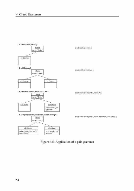
4 Graph Grammars
t:Table
c1:Column
t:Table
c1:Column c2:Column
t:Table
c1:Column c2:Column
t:Table
c1:Column
name="Order“
name="Order“
name="Order“
name="Order“
name="order_no"type="int"
name="customer_name"type="String"
c2:Column
name="order_no"type="int"
create table order ( A );
create table order ( A, A );
create table order ( order_no int, A );
create table order ( order_no int, customer_name String );
1. createTable("Order")
2. addColumn()
3. completeColumn("order_no", "int")
4. completeColumn("customer_name", "String")
Figure 4.5: Application of a pair grammar
54

5 TGG schema language
Relying on the initial idea of triple graph grammars as presented in the precedingchapter we now describe our Triple Graph Grammar approach in detail. Further-more, we discuss how the concepts of our approach can be mapped to the QVTstandard. More precisely, we focus on the relational part of QVT.
As we have motivated in Chapter 2 languages can be described using the MOF.Therefore, we present our TGG language as a MOF metamodel. Figure 5.2 de-picts the package hierarchy of our approach. Our approach itself is based on theMOF. To recall MOF basically consists of the UML infrastructure and adds anumber of additional constraints. Therefore, our approach which resides in theTGGs package imports the Core::Constructs package of the UML infrastructure.The TGGs package contains three subpackages Packages, IntegrationLinkTypes,and Rules. The packages Packages and IntegrationLinkTypes contain the schemapart of our TGG language whereas the rule part resides in the last package Rules,which will be explained in the next chapter.
5.1 Package dependencies
Figure 5.1 shows the diagram of the Packages package. In MOF and UMLpackages provide means to modularize and structure models. Well modular-ized and structured models are more readable and maintainable. Modulariza-tion can be used to express separation of concerns as well as responsibility is-sues. Furthermore, modularization can be used to improve reusability of mod-els. Usually, packages constitute namespaces for the elements contained in them.Namespace means that each element can be uniquely identified by its contain-ing package and its name. Thus, each package cannot contain two or more el-ements that have the same name. Additionally, packages hide their containedelements from elements contained in different packages. When an element of apackage wants to refer to an element of another package the elements of the re-ferred package must be made visible for the referring package first. As depicted
55

5 TGG schema language
Packages
Package(from Core::Constructs)
IntegrationPackageIntegrationPackageMerge
mergingIntegrationPackage{redefines mergingPackage}
mergedIntegrationPackage{redefines mergedPackage}
nestingIntegrationPackage{redefines nestingPackage}
nestedIntegrationPackage{redefines nestedPackage}
*
0..1
PackageMerge(from Core::Constructs)
IntegrationLinkType(from TGGs:IntegrationLinkTypes)
ownedIntegrationLinkType{redefines ownedMember}
*
Figure 5.1: TGGs::Packages diagram
in Figure 5.1 IntegrationPackages which represent the package conceptof our approach inherit from MOF package. Thus, IntegrationPackagescan import arbitrary MOF packages in order to get access to their containedelements. Furthermore, IntegrationPackages can be nested into eachother in order to form package hierarchies. IntegrationPackages maymerge other IntegrationPackages using the same semantics as the packagemerge from MOF (cf. Section 2.2). Finally, IntegrationPackages containIntegrationLinkTypes as described below.
5.2 Basic integration link type concepts
Integration link type declaration
The crucial concept of Figure 5.3 is IntegrationLinkType. An Integra-tionLinkType in our approach declares a type of correspondence links. Somerelated TGG approaches such as [Bec08] rely on the declaration of different typesof correspondence links as well. In contrast, TGG approaches such as [Wag01]rely on a single type of correspondence links only. Although, a single link typemay be sufficient for some use cases the declaration of multiple link types allowsfor the specification of more sophisticated TGG rules. Furthermore, a dedicated
56

5.2 Basic integration link type concepts
Core::Constructs
<<import>>
TGGs
Packages IntegrationLinkTypes Rules<<import>> <<import>>
Figure 5.2: Package hierarchy of our TGG approach
link type that states that a requirement is tested by a test case provides moreinformation to a user than a generic link type that only states that one modelelement is linked to another model element.
Since an IntegrationLinkType inherits from MOF::Association inour approach each IntegrationLinkType links two MOF::Properties(i.e., in our approach references to MOF::Classes). These Properties ex-press which type of source elements may be linked with which type of targetelements by links of the regarded IntegrationLinkType.
In our running example (cf. Figure 5.4) we declare, among others, the inte-gration link types PackageToSchema, ClassToTable, and SubClass-ToTable. The integration link type PackageToSchema declares a type forcorrespondence links that link a Package from the class diagram domain with aSchema of the database schema domain. Similarly, the integration link typesClassToTable and SubClassToTable declare types of correspondencelinks that link Classes with Tables. The reason for declaring two integra-tion link types for linking Classes with Tables is that in our approach eachintegration link type is the owner of at most one TGG rule (declaration). The rea-son for this is that we aim at compliance to the QVT standard as far as possible.TGG link types correspond to relations in QVT. Each relation in QVT has at mostone domain pattern as pointed out in Section 3.3.2. In order to implement the
57

5 TGG schema language
Class(from Core::Constructs)
Association(from Core::Constructs)
IntegrationLinkTypepriority : Integer = 0
IntegrationLinkTypes
WhereDependencycallingIntegrationLinkType{redefines source}
calledIntegrationLinkType{redefines target}
Rule
ownedRule{redefines ownedOperation}
linkType{redefines type}
Operation(from Core::Constructs)
DirectedRelation(from Core::Constructs)
Figure 5.3: TGGs::IntegrationLinkTypes diagram
requirements R1 and R2 from Section 3.1 we need two TGG rules and, therefore,two integration link types.
Multiplicity constraints
Finally, the (association) ends of each IntegrationLinkType are providedwith Multiplicities. These multiplicities constrain with how many modelelements of the target type one model element of the source type is linked with andvice versa. Using multiplicity constraints the user can express that for instanceeach requirement must be tested by at least one test case. The other way roundthe user can claim that each test case tests exactly one requirement. Multiplicityconstraints are not regarded at model integration time. Rather, these constraintsare evaluated when the user wants to know whether two integrated models areconsistent with each other or not by means of a completeness check.
Regarding our running example the TGG schema depicted in Figure 5.4 statesthat each Class is linked with up to one Table by a link of type ClassTo-Table. Furthermore, each Table is linked with exactly one Class by a link
58

5.3 Sophisticated integration link type concepts
Package SchemaPackageToSchema
1 1
Class TableClassToTable
0..1 0..1
SubClassToTable
0..10..*
Figure 5.4: Basic concepts of a TGG schema
of type ClassToTable. Both constraints are implied by requirement R1 fromSection 3.1. The requirement demands that only persistent classes are mappedto tables. The other way around it is obvious that each table corresponds to one(main) class. Requirement R2 demands that each persistent class which inher-its from another class is mapped to the same table the parent class is mappedto. Therefore, each Class is linked to up to one Table by a link of typeSubClassToTable. The other way around each Table is linked with an ar-bitrary number of (sub-)Classes by links of type SubClassToTable.
5.3 Sophisticated integration link type concepts
Integration link type attributes
Besides the basic integration link type concepts that are supported by most of therelated TGG approaches our approach provides the following additional concepts.Since in our approach IntegrationLinkType inherits from MOF::Classeach IntegrationLinkType owns a number of MOF::Properties (i.e.,attributes in this case). Thus, each instance of an IntegrationLinkType(i.e., a particular correspondence link) can be provided with meta-information onthe link (e.g., name of the user that created a link, timestamp of link creation).Furthermore, these attributes can be used to store more technical information thatis incorporated by TGG rules. We will give an example in the chapter on TGGrules (cf. Chapter 6).
59
5 TGG schema language
OCL constraints
Furthermore, IntegrationLinkTypes can be associated with OCL con-straints. Similar to the multiplicity constraints mentioned above OCL constraintsare not considered at model integration time. Rather, these constraints are checkedwhen the user wants to test a particular correspondence link for consistency. Thisconcept is motivated by a requirement of one of our industrial partners whichstated that the condition under which two model elements should be linked witheach other does not necessarily coincide with the condition under which such alink should be considered as consistent. However, that means that integratingtwo models with each other might result in the creation of integration links thatare considered as inconsistent. This conflicts with the intention of automaticallykeeping two models consistent with each other. Therefore, we clarify that OCLexpressions that are attached to IntegrationLinkTypes should be regarded as ad-ditional constraints that are not part of the actual model integration specification.Nevertheless, these OCL expressions improve the expressiveness of our approachand are requested by our industrial partners.
As an example we take a look at a model integration scenario of one of ourindustrial partners which deals with the integration of a requirements documentkept in Doors and a corresponding test case specification kept in CTE. The con-dition that states that a requirement and a test case should be linked to each otheris that the test case refers to the identifier of the requirement. As we will see inChapter 6 this condition can be expressed as a regular TGG rule. However, inthe integration scenario each link between a requirement and a test case shouldonly be considered consistent if the description of the requirement additionallycontains the name of the corresponding use case.
That means that during model integration each test case will be linked to therequirement with the matching identifier. If there is no such requirement the testcase simply will not be linked. After the creation of all integration links eachintegration link will be checked whether the attached requirement contains thename of the test case or not. If the regarded requirement does not contain thename of the linked test case the integration link will be considered inconsistent.
Generalization on link integration types
As we have explained above we need two TGG rules in order to map a class toa table in our running example. One rule deals with the mapping of a persistent
60

5.3 Sophisticated integration link type concepts
class which does not inherit from another class. The other rule deals with themapping of a persistent class which does inherit from another class. Actually,this is not sufficient because we are lacking a rule that deals with the mappingof a persistent class which inherits from a persistent class which in turn inheritsfrom a third class. The introduction of an additional link integration type thatowns the third rule does not really solve this problem. Doing so would force usto come up with a fourth rule and so on. Since we want to attach each integrationlink type with at most one TGG rule as explained above we cannot attach thethird rule to one of the already existing link integration types. The solution wehave in mind is that the link integration type that deals with the integration ofa persistent class which inherits from another class inherits from the first linkintegration type. Doing so we can come up with a TGG rule that is applicable toany persistent class which inherits from another class regardless whether this classitself inherits from another class or not. The reason is that a rule which applies toa more abstract link integration type also applies to link integration types whichinherit from the abstract link integration type. For an example we again refer thereader to Chapter 6.
However, as we pointed out in [KKS07] in detail it is not possible to let anintegration link type inherit from arbitrary other link integration types.
Priorities of link integration types
While performing a particular model integration task the situation can arise thatmultiple TGG rules (more precisely the operational rules derived from the TGGrules as described in Chapter 7) are applicable. Usually it is not intended that allrules which are applicable actually are applied. Another possibility would be toarbitrarily choose one of the applicable rules and disregard the others. Normally,this is not intended, too. Finally, the user can be asked to select one of the appli-cable rules. In large scale model integration scenarios the number of such userinteractions might be quite large and should, therefore, be avoided.
In order to avoid the situation that more than one rule might be applicable theuser would be facing the task of writing TGG rules that ensure that only one ofthem would ever be applicable at a time. An algorithm which decides whethera given set of TGG rules has this property is out of scope for this work. Usu-ally users want to use so-called Negative application conditions (NACs) in orderto ensure this property. As we will explain in Section 7.3 NACs cause serious
61

5 TGG schema language
p:Package
<<create>> <<create>>
s:Schema
<<create>>
name := p.name
ps:PackageToSchema
a. PackageToSchema ()
p:Package
<<create>> <<create>>
s:Schema
<<create>>
name := n
ps:PackageToSchema
b. PackageToSchema ( n : String )
name := n
Figure 5.5: TGG rule a. without and b. with parameter
problems in the context of TGGs. Therefore, our approach does not support themat all. Rather, we provide the concept of priorities. Each integration link typeis assigned with a priority. In the situation where more than one rule is applica-ble only the rule with the highest priority actually is applied. If there are moreapplicable rules that have the same highest priority we apply all of them. This be-havior conflicts with the property of graph grammars that each element is createdby one graph grammar rule only (cf. Section 7.2). We intentionally disregard thisproperty as the possibility for applying multiple rules at the same time increasesthe expressiveness of our approach. Users that dislike this possibility can easilyavoid it by assigning different priorities to rules which might conflict (i.e., rulesthat deal with the integration of model elements of the same type) during ruleapplication.
Parametrized rule declaration
Normally, approaches that are based on the initial TGG approach from 1994 (cf.Section 4.5) do not allow for parametrized TGG rules. From a formal point ofview these approaches run into problems when a rule is supposed to express thatthe value of an attribute of a model element from one model should equal thevalue of an attribute of a model element of the other model. In order to expressthis situation these approaches come up with rules like depicted in Figure 5.5a1.The problem with such a rule is that the depicted constraint accesses the value ofan attribute of a model element that is just about to be created. That means that the
1The reader is advised to regard the depicted rules as simple graph rewriting rules as presented inChapter 4.
62
5.3 Sophisticated integration link type concepts
desired attribute value is not available and the presented rule must be consideredincorrect.
Thus, the desired constraint should be expressed as shown in Figure 5.5b.Rather than accessing the value of an attribute of a model element the value isprovided as a parameter of the TGG rule. The desired constraint is implicitlyexpressed as the value of both considered attributes is set to the value of the pa-rameter. Therefore, the values of both attributes are equal.
As we will explain in Section 7.1 parameters that are used in the way presentedabove will be resolved during the derivation of operational rules. Thus, the op-erational rules do not carry these parameters anymore which otherwise must beprovided with actual values at rule application time by the user. Furthermore, theuser may intentionally choose to use parameters that cannot be resolved at rulederivation time. The consequence is that the derived operational rules still carrythe unresolved parameters which must be provided with actual values at rule ap-plication time by the user as mentioned above.
where-dependencies
Up to now the specificator has no means for explicitly manipulating the order inwhich the specified rules will be applied at rule application time. On the one handthis is intended as TGGs are meant to be declarative. On the other hand some-times this can be quite inconvenient and results in specifications that are hard tounderstand which is surely not intended. Moreover, most TGG rules require tomatch a context which easily could have been provided by a previous integrationstep. This results in an undesired matching overhead with unnecessary high costsat runtime. For instance, the application of the rule depicted in Figure 5.6a re-quires for each class the matching of the package, the integration link, and theschema. Usually the TGG rules are organized in such a way that the package, theintegration link, and the schema will be handled first. After that the content of thepackage (i.e., the classes) will be dealt with. That means that for each of theseclasses the context remains the same and should not be matched every time overand over again.
On a first glance this seems to be just a technical issue. Nevertheless, we adoptthe concept of where-dependencies from the QVT standard. To recall in QVT awhere pattern can be used in order to invoke a subsequent relation from the currentrelation. Thereby, the invoking relation may pass model elements to the invoked
63

5 TGG schema language
p:Package
<<create>> <<create>>
s:Schema
<<create>>
ps:PackageToSchema
a. ClassToTable ( n : String )
c:Class t:Tablect:ClassToTable
name := nname := n
<<create>> <<create>>
p:Package
<<create>> <<create>>
s:Schema
<<create>>
ps
c. ClassToTable ( ps : PackageToSchema, n : String )
c:Class t:Tablect:ClassToTable
name := nname := n
<<create>> <<create>>
b.
Package SchemaPackageToSchema
Class TableClassToTable
<<where>>
Figure 5.6: Examples of a. a TGG rule without provided context, b. the declara-tion of a where-dependency, and c. a TGG rule with provided context
relation. Similarly, we allow a TGG rule to invoke another TGG rule as illustratedin Figure 5.6b. In accordance to QVT we call a TGG rule that is not invoked byanother TGG rule a top-level rule, whereas the remaining rules are called non-top-level rules. In contrast to the QVT standard we do not allow the invokingTGG rule to pass arbitrary model elements to the invoked TGG rule. Rather, weassume that the invoking TGG rule passes the just created integration link to theinvoked TGG rule as this is the most useful model element (cf. Figure 5.6c).Thus, our concept of where-dependency is slightly less expressive than QVT’swhere-concept. However, concerning the example of dealing with packages andcontained classes the more operational concept of where-dependencies appears tobe more intuitive and user-friendly. Therefore, invoking TGG rules from other
64
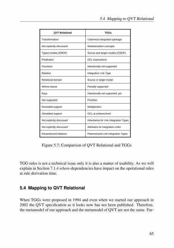
5.4 Mapping to QVT Relational
QVT Relational TGGs
Transformation Outermost integration package
Not explicitly discussed Modularization concepts
Simulated support OCL at schema level
Not explicitly discussed Inheritance for Link Integration Types
Not explicitly discussed Attributes for Integration Links
Typed models (EMOF) Source and target models (CMOF)
Predicates OCL expressions
Functions Intentionally not supported
Relation Integration Link Type
Relational domain Source or target model
Where-clause Partially supported
Keys Intentionally not supported, yet
Not supported Priorities
Simulated support Multiplicities
Parametrized relations Parametrized Link Integration Types
Figure 5.7: Comparison of QVT Relational and TGGs
TGG rules is not a technical issue only it is also a matter of usability. As we willexplain in Section 7.1.4 where-dependencies have impact on the operational rulesat rule derivation time.
5.4 Mapping to QVT Relational
When TGGs were proposed in 1994 and even when we started our approach in2002 the QVT specification as it looks now has not been published. Therefore,the metamodel of our approach and the metamodel of QVT are not the same. Fur-
65
5 TGG schema language
thermore, since the current metamodel of QVT suffers from a number of defectsas pointed out in Section 3.4 we chose not to switch to QVT’s metamodel, yet.
However, the QVT standard looks very similar to our own approach. As theQVT standard aims at being the most important and accepted model integrationstandard in industry we want to informally provide a mapping of concepts fromour approach to concepts from the QVT standard. By means of these mappingswe claim that our approach provides some sort of implementation of the QVTstandard based on the well-known formalism of graph grammars. Furthermore,we can use these mappings to replace the metamodel of our approach to the meta-model of the QVT standard when its defects have been fixed. We focus on theQVT relational package (and the underlying base package) as it corresponds toour TGG approach and is meant to be equally expressive as the QVT core pack-age.
First of all, a transformation in QVT corresponds to the outermost integra-tion package in our TGG approach. Our TGG approach provides means for themodularization of model integration specifications (i.e., package dependencies).QVT inherits such concept from MOF but does not explicitly discuss the seman-tics and the usage of these concepts. Therefore, we have to assume that theseconcepts more or less are accidentally included in QVT. Typed models in QVTcorrespond to typed (source and target) models in our approach. QVT’s predi-cates correspond to OCL constraints that are attached to integration rules in ourapproach. Functions which represent queries in QVT have no counterpart in ourTGG approach. Rather, a number of queries will be derived from each declarativeTGG rule. Additional queries cannot be considered as part of a declarative modelintegration specification and, thus, have to be specified operationally. Each rela-tion in a QVT specification corresponds to a integration link type in our approachwhereas each relational domain corresponds either to the source or the targetmodel in our TGG approach. As already explained above a subset of possiblewhere expressions in QVT can also be specified in our TGG approach. Finally, asthe concept of keys is unsatisfactory in QVT there is no corresponding counterpartin our TGG approach, yet (cf. Section 3.4).
The concepts priorities, multiplicities, and OCL expressions at schema levelin our TGG approach have no explicit counterparts in QVT. Nevertheless, multi-plicities and OCL expressions at schema level can be represented as functions inQVT. To the best of our knowledge priorities cannot be simulated in QVT at all.Rather, QVT relies on Negative Application Conditions (cf. Section 7.3) at rulelevel. Our TGG approach supports inheritance on link integration types and, thus,
66

5.4 Mapping to QVT Relational
on link integration rules. Furthermore, our approach allows for the specificationof attributes for link integration types. Again, QVT inherits both features fromMOF but does not discuss their semantics for relations. Finally, QVT as well asour TGG approach supports the parametrization of relations and link integrationtypes, respectively. Figure 5.7 summarizes the correspondences and differencesbetween QVT and our TGG approach.
67

6 TGG rule language
Besides a triple graph schema as presented in the preceding chapter a triple graphgrammar is composed of a set of triple graph grammar rules. Again we describebasic and sophisticated elements that are supported by our approach and providea mapping to the QVT (relational) standard.
Conceptually, a TGG rule describes the simultaneous modification of source,target, and integration model. The set of all TGG rules of a TGG specification,therefore, describes the simultaneous evolution of source, target, and integrationmodel. As the simultaneous evolution of all regarded models is seldom useful inpractice a number of operational rules which can be applied in order to realizevarious integration scenarios will be derived from each TGG rule as described inChapter 7.
6.1 Basic elements
Figure 6.1 presents the package containing the metamodel of TGG rules in ourapproach. Basically, each declaration of a TGG Rule (cf. Chapter 5) is pro-vided with a RulePattern which constitutes the body of the rule. EachRulePattern consists of a number of RuleElements. RuleElementseither are Objects, Links, or IntegrationLinks. RuleElements thatare marked as created by setting the value of isCreated to true are meantto be created during rule application. In terms of graph rewriting these elementsbelong to the right-hand side of the rule. RuleElements that are not marked ascreated (i.e., isCreated == false) are meant to be matched during ruleapplication. In terms of graph rewriting these elements belong to the left-handside of the rule. To recall when one or more elements of the left-hand side of a rulecannot be matched during rule application the application of the rule as a wholefails and no modifications are committed. Objects and Links are matched orcreated either in the source or the target model, whereas IntegrationLinksreside in the integration model.
68

6.1 Basic elements
Rules
Rule(from TGGs::IntegrationLinkTypes)
RulePattern
RuleElementInstanceSpecification(from Core::Constructs) isCreate : Boolean = false
ruleElements
rulePattern
*
Object Link
rulePattern
IntegrationLink
sourceObject
targetObject
sourceDomainObject{redefines sourceObject}
targetDomainObject{redefines targetObject}
Association(from Core::Constructs)
type{redefines classifier}
IntegrationLinkType{TGGs::IntegrationLinkTypes}
type{redefines classifier}
Class(from Core::Constructs)
type{redefines classifier}
Figure 6.1: TGGs::Rules diagram
Basically, matching an Object means that the depicted Object is boundto an element of the appropriate type in the regarded model. Attached Linksand linked Objects, called the context of this Object, restrict the number ofpossible matches. Matching a Link means that the depicted Link is bound to alink of the appropriate type in the regarded model. Furthermore, the Objectsattached to the Link must also be bound and linked to each other by the regardedlink. Creating Objects and Links means that new elements of the providedtype are added to the regarded model and attached to any provided context.
As RuleElements inherit from InstanceSpecification each Rule-Element can be provided with an arbitrary number of Slots. A Slot containsa value specification. A value specification can be used to restrict the numberof candidates for a match by demanding that an attribute of a candidate has thespecified value. Naturally, this kind of value specification can only be used forelements of the left-hand side of a rule. Furthermore, a value specification can beused to initialize the value of an attribute of an element of the right-hand side ofa rule.
69

6 TGG rule language
p:Package s:Schemaps:PackageToSchema
ClassToTable(n:String)
c:Class t:Tablect:ClassToTable
<<create>><<create>> <<create>>
persistent:=true
<<create>> <<create>>
Figure 6.2: TGG rule with a simple value specification
Figure 6.2 depicts a TGG rule with a simple value specification. Accordingto the requirements of our running example as pointed out in Section 3.1 onlypersistent Classes are transformed into a corresponding Table. There-fore, the value of the persistent attribute of the new Class is set to trueby the given value specification.
Besides simple value specifications, whose right-hand sides are simple values,our approach supports two additional constructs. First of all, the right-hand sideof a value specification may be an arbitrary expression which has to be evalu-ated at rule application time. Secondly, such an attribute expression may refer toparameters declared in the rule declaration as presented in Section 5.3.
Figure 6.3 illustrates the more complex value specification expressions. Firstof all, the value of the name attributes of the objects a and col depend on theparameter n which is declared in the signature of the rule. Secondly, the value ofthe attribute name of col has to be calculated according to the given expression.Thereby, we realize the requirement of our running example given in Section 3.1that the names of some Columns must be provided with prefixes1.
6.2 Sophisticated elements
Currently, our TGG approach does not provide any additional sophisticated ruleelements. However, there are a number of imaginable extensions. Although ourapproach does not implement these extensions yet, we want to discuss some ofour ideas now.
1In fact we provide the names of all columns with prefixes but the prefixes initially are blank.
70

6.2 Sophisticated elements
c:Class t:Tablect:ClassToTable
AttributeToColumn(n:String)
a:Attribute ac:AttributeToColumn<<create>>
name:=n
<<create>>
<<create>>
col:Column
p:PrimitiveDataType
<<create>>
name:=ct.prefix + ntype:=p.name
attributes<<create>>
<<create>>type
Figure 6.3: TGG rule with complex value specification
First of all we want to emphasize that our approach intentionally does not sup-port Negative Application Conditions (NACs). As we will explain in Section 7.3NACs cause presumably irresolvable problems at rule derivation time. Be advisedthat our approach provides a powerful replacement for NACs based on prioritiesas explained in Section 5.3. So far we see no way for adopting NACs into ourapproach in future.
Furthermore, we intentionally do not allow for marking TGG rule elementswith the «destroy» keyword as presented in Section 4.4. In contrast to NACsthe «destroy» keyword does not cause problems at rule derivation time. Anyrule elements that are marked with «destroy» in a declarative TGG rule wouldalso be marked with «destroy» in the resulting derived rules. Graph gram-mars in contrast to graph rewriting systems are meant to construct a graph justby adding new (terminal) elements. The reason is that the deletion of (terminal)graph elements in a graph grammar rule would make it very hard if not impossibleto parse an existing graph. Parsing a graph means to calculate a sequence of ruleapplications that results in the regarded graph.
For instance in the context of TGGs forward transformation conceptuallymeans to parse the source graph in order to calculate the sequence of rule ap-plications2 that resulted in the source graph. The target graph can then be cre-ated by applying the same sequence of corresponding rules3. The same appliesmore or less for the other integration scenarios as well. Therefore, being ableto (efficiently) parse a graph is essential for TGGs. In order to achieve this weintentionally disallow for the deletion of model elements in declarative TGG rule
2This refers to the source parts of TGG rules.3This refers to the target parts of TGG rules.
71

6 TGG rule language
specifications. Again, we do not plan to add the feature of model element deletionto our approach in the future4.
Some graph grammar-based approaches provide the concept of optional ruleelements. Thereby, optional means that the considered rule does not fail when anoptional rule element cannot be bound. However, when an optional rule elementcan be bound it can be modified by the considered rule (e.g. it can be deleted,attached to other rule elements, or its attribute values can be changed). In factoptional rule elements are just an abbreviation for more complex rules whichcheck whether the optional elements can be bound and modifies them.
This concept can easily be adopted to TGGs as it is. Generally, optional ruleelements themselves are only allowed on the left-hand side of a rule. However,optional rule elements are only useful when they are subject to modifications.Therefore, for rule derivation purposes it has to be analyzed what happens to op-tional rule elements and their attached modifications when deriving an operationrule from the considered TGG rule. This is future work.
A similar discussion concerns the concept of set nodes. A set node is boundto the set of all found matches of the given node specification. It allows for themodification of all nodes in the calculated set of matches. Again, it has to beanalyzed what happens to set nodes while the derivation of operational rules.The concepts of optional and set become even more sophisticated when they areapplied to subgraphs rather than single nodes. Again, this is future work.
The last concept we want to propose is the concept of optionally created ruleelements. Optionally created rule elements should only be created when they can-not be bound at rule application time. This ensures that an optionally created ruleelement is created only ones when applying the regarded rule and reused in sub-sequent applications of this rule. Again, this concept is only an abbreviation fora more complex rule which checks whether the given rule element can be boundand creates it otherwise. This concept is particularly useful when a consideredrule contains multiple optionally created rule elements.
For rule derivation purposes each rule element that is marked as optionally cre-ated and has to be moved to the left-hand side of the derived rule will be transferedand is marked as a normal rule element. The reason is that after the applicationof the regarded declarative rule it is guaranteed that the considered rule element
4Observe that QVT also does not support the deletion of model elements.
72

6.3 Mapping to QVT Relational
Value SpecificationPropertyTemplateItem
RuleElementTemplateExpression
RulePatternPatterns (except where-pattern)
RuleRule
TGGsQVT Relational
Figure 6.4: Comparison of QVT Relational and TGGs (cont.)
exists. Therefore, the rule element has to be matchable when applying the corre-sponding operational rule. Again, this is future work.
6.3 Mapping to QVT Relational
Even on the level of rules QVT and our TGGs look quite similar to each other.The term Rule from our approach corresponds to the term Rule from QVT. InQVT each rule consists of a number of Patterns (e.g., when- and where-patterns,domain patterns). The set of Patterns other than the where-pattern of a QVTrule corresponds to the RulePattern of a TGG rule. Thereby, the term Template-Expression from QVT corresponds to the term RuleElement from our TGG ap-proach. TemplateExpressions that have not already been bound beforehand (e.g.by a when-pattern) correspond to the RuleElements on the right-hand side of theregarded TGG rule, whereas already bound TemplateExpressions correspond tothe RuleElements on the left-hand side. Furthermore, PropertyTemplateItems thatare attached to Template Expressions5 correspond to Value Specifications in ourapproach. Figure 6.4 summarizes these correspondences.
Figure 6.5 depicts a TGG rule and the corresponding QVT rule in order to illus-trate the similarities of both approaches. The TGG rule from Figure 6.5a. meansthat for each persistent class that is added to an already existing package a cor-responding table will be added to an already existing schema which correspondsto the regarded package and vice versa. Thereby, the names of the class and the
5More precisely: ObjectTemplateExpressions.
73

6 TGG rule language
p:Package s:Schemaps:PackageToSchema
a. ClassToTable(n:String)
c:Class t:Tablect:ClassToTable
<<create>><<create>> <<create>>
name:=npersistent:=true name:=n
<<create>> <<create>>
p:Package s:Schema
b. ClassToTablewhenPackageToSchema(p, s)
c:Class t:Tablename=npersistent=true name=n
<<domain>> <<domain>>
cd db
Figure 6.5: Comparison of a. a TGG rule and b. the corresponding QVT rule
table are identical. Similarly, the QVT rule from Figure 6.5b. means that a classis related to a table when the package to which the class belongs is related to aschema that contains the table. Furthermore, the names of the class and the tablemust be the same.
Both depicted rules are meant to be declarative and, therefore, can be appliedin order to ensure the consistency between a class and its corresponding table.If there is no corresponding table for a class such a table will be created andvice versa. Thus, the TGG rule and the QVT do not only look quite similar toeach other; they basically have the same semantics. Generally speaking the QVTstandard and our TGG approach are intentionally nearly identical.
The major benefit of TGGs is that they rely on a proper formal foundation, i.e.theory of graph grammars. In contrast the semantics of QVT is more or less onlyinformally given. On the one hand TGGs can be utilized as the missing formalfoundation for the QVT standard. On the other hand the implementation of our
74

6.3 Mapping to QVT Relational
TGG approach can, therefore, be regarded as one of the first implementations ofthe declarative part of QVT.
75
7 Operational rules
In this chapter we present how we automatically derive operational graph tran-formations from declarative triple graph grammars as presented in the precedingchapters. We want to emphasize that the rule derivation strategies as presented inthis chapter can be regarded as a proposal for rules that are useful for our modelintegration approach. Nevertheless, we do not claim that the set of derived rules iscomplete. The reader may come up with own additional rules if they feel need to.Furthermore, we illustrate in which way these operational graph transformationscan be applied in order to realize the desired integration of models.
7.1 Derivation strategies
Basically, a TGG describes the simultaneous evolution of two models and theirrelationship by means of correspondence links. In practice the simultaneous evo-lution is seldom useful. The application of a TGG as it is would mean that whilea user is modifying one model by using a tool he is simultaneously modifyinganother model residing in another tool which might be used by a different userand vice versa. That means that a user of one tool is constantly bothering otherusers with updates of their models. Rather, each user wants to work with theirtools as usual and synchronize with changes done by other users only at certainpoints of time.
Such a synchronization needs the identification of changes to models sincethe last synchronization. The identified changes must then be applied to relatedmodels correspondingly. The proper application of changes requires appropri-ate operations which ensure that the considered models are consistent with eachother after synchronization. The crucial point of TGGs is that the set of neededoperations can automatically be derived from the declarative rules.
76

7.1 Derivation strategies
7.1.1 Classical rules
The initial TGG approach from 1994 [Sch94] identified the following three in-tegration tasks which should be covered by the derivation of operational graphrewriting rules from the declarative TGG rules.
1. Model transformation. This integration task arises when one model hasgot new elements that should be related to elements in the other model butthe other model does not contain these corresponding elements yet and viceversa. Therefore, corresponding elements have to be added to the secondmodel and have to be related to the new elements of the first model bymeans of correspondence links.
2. Consistency checking. This integration task arises when the user wantsto check whether two models are consistent to each other. If the modelsare inconsistent the user wants to get a report of all inconsistent modelelements. To this end all existing correspondence links have to be checkedwhether they are still valid. Furthermore, each model has to be checkedwhether it contains model elements that should correspond to other modelelements but do not yet.
3. Correspondence link creation. This integration task arises when the userhas got two models that are not provided with any correspondence infor-mation yet and wants to calculate the missing correspondence informationby means of correspondence links.
7.1.2 Additional rules
In addition to the classical rules we have identified the following integration tasks.
4. Attribute value propagation. This integration task arises when two ele-ments are consistent to each other by means of their structural properties buttheir attribute values do not match (i.e., the graph pattern of the TGG rulecan be matched but some of the attribute conditions are violated). Someof the attribute values of the corresponding elements have to be adjusted inorder to recover consistency.
5. Element deletion propagation. This integration task arises when a cor-respondence link has a dangling end. This can only occur if the user has
77

7 Operational rules
intentionally deleted the element that was attached to the regarded link be-forehand. In order to recover consistency the corresponding link as well asthe remaining corresponding element have to be deleted as well since thatreflects the intention of the user.
6. Correspondence link deletion. This integration task arises when two el-ements are related by a correspondence link but should not be linked any-more. The solution is to just delete the undesired correspondence link.
7.1.3 Operational rule derivation
Using the declarative TGG rule from Fig. 6.5a. of our running example we ex-plain the derivation of our operational rules. The derivation of an operationalrule from a declarative rule consists of two steps. Firstly, we have to process thepattern of the declarative rule and to deal with the contained attribute assertions.Secondly, we have to resolve any parameters the declarative rule might have suchthat the resulting operational rule is unparameterized. If we cannot eliminate allparameters the resulting rule requires user interaction at application time askingthe user for the actual value of each remaining parameter. Basically, the patternof an operational rule is the same as the pattern of the corresponding declarativerule. The operational rule is derived from the declarative rule by moving someelements of the pattern from the right-hand side of the rule (i.e., elements that arecreated by rule application) to the left-hand side of the rule (i.e., elements that areto be matched at rule application time).
Derivation of model transformation rules
In order to support model transformation we derive two operational rules froma given declarative rule. One rule is called forward transformation rule, the otheris called backward transformation rule. Forward transformation is a task thattransforms one model into another model in the "natural" direction of the trans-formation. Backward transformation performs this task the other way round. It isup to the user to define which direction is considered to be natural. For instance itcan be considered natural if one model is from an earlier development phase thanthe other and the transformation is performed in this direction, it can be consid-ered natural if one model is more abstract than the other and the transformation isperformed in this direction, and so on. We call the model that is transformed intothe other by transformation rules the source model. We call the other model thetarget model.
78

7.1 Derivation strategies
In order to derive the forward transformation rule from a TGG rule we moveall elements that refer to the source model that currently belong to the right-handside of the rule to the left-hand side of the rule. Since elements of the sourcemodel that are marked as optional create in the declarative rule would be createdwhile rule application if they do not already exist these elements generally1 be-come plain obligate elements during rule derivation. This means that elementsfrom the source model that would have been created by the application of thedeclarative rule now have to be matched in the source model in order to apply theresulting forward transformation rule. Only elements from the target model andthe correspondence model will be created now. This results in the desired modeltransformation. Furthermore, we replace any attribute assignment of elements ofthe source model by corresponding attribute conditions. This means that the at-tribute values of elements of the source model are no longer modified. Rather,the attributes are now checked for certain values. This corresponds to movingelements from the right-hand side of a pattern to the left-hand side. Finally, weresolve any parameter of the declarative rule if possible as follows. We considerthe occurrence of a parameter in the source model as the definition of the param-eter. We consider the occurrence of the same parameter in the target model as theusage of the parameter. Therefore, we replace any usage of a parameter by itsdefinition.
Fig. 7.1 illustrates the derivation process. The derived forward transforma-tion rule takes the to be transformed Class c as input. From c the rule navi-gates over the Package p and the correspondence link ps to the Schema sto which a new Table t should be added to. The rule then creates t and acorrespondence link ct in order to link c and t with each other. Furthermore,by resolving the parameter n of the considered TGG rule the value of the nameattribute of t is set to the name attribute of c. Correspondingly, we derive thebackward transformation rule from the considered TGG rule by switching theroles of source and target model.
Derivation of consistency checking rules
An operational rule that checks a given correspondence link whether it still isvalid does neither create new elements nor modify existing ones. Therefore, wehave to move all elements from the right-hand side of the pattern of the declarativerule to the left-hand side of the pattern in order to derive the desired operationalrule. Observe that the consistency of the given correspondence link intentionally
1This applies to all rule derivation strategies.
79

7 Operational rules
p:Package
ClassToTable.performForwardTransformation ( c : Class )
c ct:ClassToTable
ps:PackageToSchema s:Schema
t:Tablename := c.name
<<create>><<create>>
p:Package
ClassToTable.performBackwardTransformation ( t : Table )
c:Class ct:ClassToTable
ps:PackageToSchema s:Schema
tname := t.name
<<create>><<create>>
a.
b.
Figure 7.1: Derived model transformation rules
does not depend on the consistency of correspondence links of the left-hand sideof the declarative rule. Otherwise, it would be unclear whether a correspondencelink is inconsistent because its rule pattern is violated, because other correspon-dence links are inconsistent, or both.
Furthermore, we also have to replace any attribute assignment by a correspond-ing attribute condition. For resolving parameters of the TGG rule we can arbitrar-ily choose one occurrence of the regarded parameter as its definition and the otheras usages. Again we replace all usages of a parameter by its definition as illus-trated in Fig. 7.2. The resulting rule now checks whether the pattern that has beenvalid at creation time of the correspondence link still can be matched (i.e., thecorrespondence link still is valid).
Derivation of correspondence link creation rules
For supporting link creation we derive two operational rules from a given TGGrule. We can link one element of one model with elements of the other model andvice versa. Therefore, we have a forward correspondence link creation rule and abackward correspondence link creation rule. The rules only differ in the element
80

7.1 Derivation strategies
p:Package
ClassToTable.checkConsistency ()
c:Class this
ps:PackageToSchema s:Schema
t:Tablename = t.name
Figure 7.2: Derived consistency checking rule
from which the pattern matching of the regarded rule starts. In order to derive thedesired rules we move all elements that refer to elements of the to be integratedmodels from the right-hand side to the left-hand side of the pattern. The onlyelement that resides at the right-hand side is the to be created correspondence link.Additionally, we replace all attribute assignments that are not owned by the to becreated correspondence link by attribute conditions. For resolving parameters ofthe TGG rule we can arbitrarily choose one occurrence except the to be createdcorrespondence link of the regarded parameter as its definition and the other asusages. Again we replace all usages of a parameter by its definition.
The derived rules are illustrated by Fig. 7.3. The forward link creation rulestarts at Class c. By navigating over Package p, the correspondence linkps, and Schema s the rule tries to find a Table t such that the given attributecondition holds. If such a Table can be matched the rule links c with t by a newcorrespondence link ct. Correspondingly, we derive the backward link creationrule from the considered TGG rule by switching the roles of source and targetmodel.
Derivation of attribute value propagation rules
In order to propagate changes of attribute values we derive two operationalrules from a given TGG rule. Again, such a propagation can be perform in for-ward and in backward direction. Therefore, we derive a forward attribute valuepropagation and a backward attribute value propagation rule. For deriving theforward attribute value propagation rule we move all elements of the right-handside of the TGG rule to the left-hand side of the resulting operational except for at-tribute assignments of target model elements that depend on the considered source
81
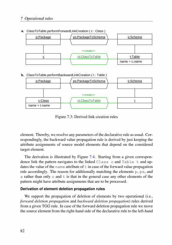
7 Operational rules
p:Package
ClassToTable.performForwardLinkCreation ( c : Class )
c ct:ClassToTable
ps:PackageToSchema s:Schema
t:Tablename = c.name
<<create>>
p:Package
ClassToTable.performBackwardLinkCreation ( t : Table )
c:Class ct:ClassToTable
ps:PackageToSchema s:Schema
tname = t.name
<<create>>
a.
b.
Figure 7.3: Derived link creation rules
element. Thereby, we resolve any parameters of the declarative rule as usual. Cor-respondingly, the backward value propagation rule is derived by just keeping theattribute assignments of source model elements that depend on the consideredtarget element.
The derivation is illustrated by Figure 7.4. Starting from a given correspon-dence link the pattern navigates to the linked Class c and Table t and up-dates the value of the name attribute of t in case of the forward value propagationrule accordingly. The reason for additionally matching the elements p, ps, ands rather than only c and t is that in the general case any other elements of thepattern might have attribute assignments that are to be processed.
Derivation of element deletion propagation rules
We support the propagation of deletion of elements by two operational (i.e.,forward deletion propagation and backward deletion propagation) rules derivedfrom a given TGG rule. In case of the forward deletion propagation rule we movethe source element from the right-hand side of the declarative rule to the left-hand
82

7.1 Derivation strategies
p:Package
ClassToTable.performForwardAttributeValuePropagation ( c : Class )
c:Class this
ps:PackageToSchema s:Schema
t:Tablename := c.name
p:Package
ClassToTable.performBackwardAttributeValuePropagation ( t : Table )
c:Class this
ps:PackageToSchema s:Schema
t:Tablename := t.name
a.
b.
Figure 7.4: Derived attribute value propagation rules
side of the operational rule. Furthermore, we attach a negative application condi-tion to this element. This means that it must be impossible to find a match for thiselement expressing that this element does not exist any more. Additionally, weattach deletion flags to all elements of the right-hand side of the declarative rulewhich belong to the target model and to the correspondence link as well. Finally,we transfer the context elements of the to be deleted elements in order to properlydelete all links to the deleted elements. The backward deletion propagation ruleis derived correspondingly.
Figure 7.5 illustrates the derivation process. In case of the forward deletionpropagation rule the pattern starts from a given correspondence link. After thatthe rule tries to match a Class c. If this does not succeed this means that theelement that has been linked by the correspondence link has been deleted in themeantime and the correspondence link now has a dangling link end. Therefore,the rule deletes the correspondence link as well as the other link end which is aTable t.
83
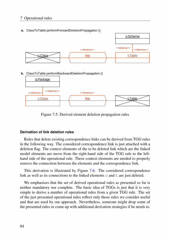
7 Operational rules
ClassToTable.performForwardDeletionPropagation ()
c:Class this
s:Schema
t:Table
p:Package
ClassToTable.performBackwardDeletionPropagation ()
c:Class this t:Table
a.
b.
<<destroy>><<destroy>>
<<destroy>>
<<destroy>><<destroy>>
<<destroy>>
Figure 7.5: Derived element deletion propagation rules
Derivation of link deletion rules
Rules that delete existing correspondence links can be derived from TGG rulesin the following way. The considered correspondence link is just attached with adeletion flag. The context elements of the to be deleted link which are the linkedmodel elements are move from the right-hand side of the TGG rule to the left-hand side of the operational rule. These context elements are needed to properlyremove the connection between the elements and the correspondence link.
This derivation is illustrated by Figure 7.6. The considered correspondencelink as well as its connections to the linked elements c and t are just deleted.
We emphasizes that the set of derived operational rules as presented so far isneither mandatory nor complete. The basic idea of TGGs is just that it is verysimple to derive a number of operational rules from a given TGG rule. The setof the just presented operational rules reflect only those rules we consider usefuland that are used by our approach. Nevertheless, someone might drop some ofthe presented rules or come up with additional derivation strategies if he needs to.
84

7.2 Application strategies
ClassToTable.deleteCorrespondenceLink ()
c:Class this t:Table
<<destroy>>
Figure 7.6: Derived link deletion rule
7.1.4 Impact of where-dependencies on rule derivation
As we have mentioned in Section 5.3 our TGG approach adopts the concept ofwhere-dependencies from the QVT standard. To recall a where-dependency be-tween a link integration type A and a link integration type B means that a rulethat is responsible for an instance a of link integration type A, invokes the cor-responding rule of link integration type B. Thereby, the invoking rule passes thejust created integration link a as an input parameter to the invoked rule. Thus, theinvoked rule does not have to match the provided integration link a and can eas-ily match the model elements linked by this integration link. One aim is to savecalculation time for recurrent matches of integration links, another is usability.
There are at least two possibilities of dealing with where-dependencies at rulederivation time. One possibility is to recursively merge the pattern of the invokedrule with the pattern of the invoking rule at rule derivation time. Although thatapproach is straight-forward it runs into severe problems if rules directly or in-directly invoke each other in a circular manner. Another possibility is to utilizethe mechanism of graph rewriting systems as PROGRES or in our case FUJABAto specify rule invocation. This time circular dependencies are not a problembecause the dependencies are not dealt with at rule derivation time. The ruleinvocation just stops as soon as a rule which would invoke another rule is notapplicable.
7.2 Application strategies
A TGG specification consisting of a TGG schema and a set of TGG rules declar-atively specifies when two given models may be considered consistent with eachother. We have just described how to derive a number of operational rules that
85
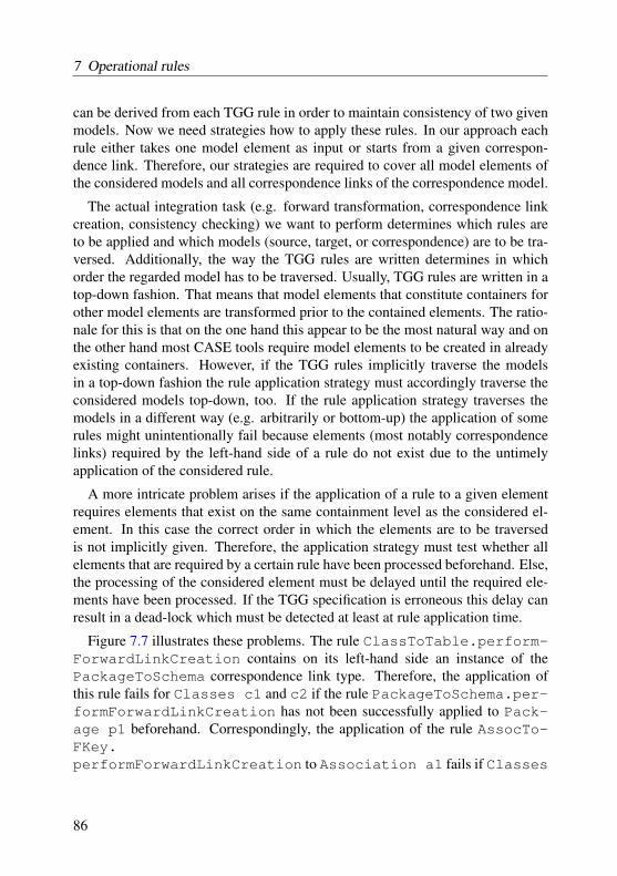
7 Operational rules
can be derived from each TGG rule in order to maintain consistency of two givenmodels. Now we need strategies how to apply these rules. In our approach eachrule either takes one model element as input or starts from a given correspon-dence link. Therefore, our strategies are required to cover all model elements ofthe considered models and all correspondence links of the correspondence model.
The actual integration task (e.g. forward transformation, correspondence linkcreation, consistency checking) we want to perform determines which rules areto be applied and which models (source, target, or correspondence) are to be tra-versed. Additionally, the way the TGG rules are written determines in whichorder the regarded model has to be traversed. Usually, TGG rules are written in atop-down fashion. That means that model elements that constitute containers forother model elements are transformed prior to the contained elements. The ratio-nale for this is that on the one hand this appear to be the most natural way and onthe other hand most CASE tools require model elements to be created in alreadyexisting containers. However, if the TGG rules implicitly traverse the modelsin a top-down fashion the rule application strategy must accordingly traverse theconsidered models top-down, too. If the rule application strategy traverses themodels in a different way (e.g. arbitrarily or bottom-up) the application of somerules might unintentionally fail because elements (most notably correspondencelinks) required by the left-hand side of a rule do not exist due to the untimelyapplication of the considered rule.
A more intricate problem arises if the application of a rule to a given elementrequires elements that exist on the same containment level as the considered el-ement. In this case the correct order in which the elements are to be traversedis not implicitly given. Therefore, the application strategy must test whether allelements that are required by a certain rule have been processed beforehand. Else,the processing of the considered element must be delayed until the required ele-ments have been processed. If the TGG specification is erroneous this delay canresult in a dead-lock which must be detected at least at rule application time.
Figure 7.7 illustrates these problems. The rule ClassToTable.perform-ForwardLinkCreation contains on its left-hand side an instance of thePackageToSchema correspondence link type. Therefore, the application ofthis rule fails for Classes c1 and c2 if the rule PackageToSchema.per-formForwardLinkCreation has not been successfully applied to Pack-age p1 beforehand. Correspondingly, the application of the rule AssocTo-FKey.performForwardLinkCreation to Association a1 fails if Classes
86

7.2 Application strategies
c1:Class a1:Association c2:Class
p1:Package
Figure 7.7: Example model for the illustration of application strategy relatedproblems
c1 and c2 which both lie an the same containment level as a1 have not been suc-cessfully processed before. Thus, processing the elements either in the followingsequence p1, c1, c2, a1 or p1, c2, c1, a1 leads to a valid result, whereas allother sequences lead to incomplete, hence invalid results.
When processing a given model element it might be the case that more than onerule is applicable. Usually, it is not intended to apply all applicable rules. Rather,the application strategy is intended to determine one rule (in rare cases a subsetof rules) that actually is to be applied. Some approaches as [Bec08] ask the userto select the desired rule. This is only feasible if the number of user interactionsis small. It would be a nightmare for a user to select more than a couple of rules.The situation becomes even worse if the user has to redo this selection every timean integration task is executed. However, in large scale model integration scenar-ios with thousands of to be integrated model elements the number of situationswhere more than one rule is applicable is much too large for user interaction. Tothis end our approach uses priorities that are provided for each rule. The ideais that the application strategy only applies those rules which priorities are thehighest. In case that there is more than one such rule we again have the choiceto either apply all rules or to ask the user. Although the number of required userinteractions would be noticeably lower we choose to blindly apply all remainingrules. If this is not the intended behavior it is up to the TGG specification to avoidthose situations. Observe that from the formal point of view the application ofmore than one rule to a single model element violates the character of a (graph)grammar. Nevertheless, practice has shown that the application of multiple rules
87

7 Operational rules
is actually required. The author is of the firm conviction that formal requirementsthat would allow for proving certain theoretical properties may be violated if theyconstrain the whole approach from being useful in practice.
Finally, when processing a given model element it might be the case that thereare multiple matches for the application of one rule. Again, some approachessuch as [Bec08] ask the user to select one match from the set of possible matchesthat should used for rule application. As mentioned above this solution is not fea-sible for large scale model integration scenarios. Therefore, we choose to blindlyapply the regarded rule to all possible matches. Again, it is up to the TGG specifi-cation to avoid such situations if this behavior is not intended. As already pointedout above this solution violates the character of a (graph) grammar but increasesusability of our approach in practice.
Altogether, we use the following application strategy for cases where we needto traverse all model elements of either the source or the target model (i.e., modeltransformation and correspondence link creation). We emphasize that an applica-tion strategy heavily depends on the way TGG rules are specified. Since we usea top-down strategy as explained above the users of our approach are forced towrite their TGG rules in a top-down fashion as well. Nevertheless, the originalTGG approach itself does not imply a certain application strategy.
1. Start with an ordered list L of all outermost model elements (i.e., elementsthat are not contained in other elements) of the to be transformed model.Initially, this list is arbitrarily ordered.
2. For each element e of L determine the set S of elements that are containedby e.
3. Arbitrarily add S to the ordered list N of elements that are to be processedat the next iteration.
4. Process each element e of L in the following way:
a) Determine the set R of operational rules that are applicable to e.
b) Only keep those rules with the highest priority.
c) For each rule r of R check whether the context of r requires elementsthat are not processed, yet.
d) If there are such elements move e from L to the beginning of N.
88

7.2 Application strategies
e) Else, apply all rules of R to e. Thereby, process all possible matchesfor each rule.
5. If N is empty the integration task has finished.
6. If N contains all and only elements of L (i.e., all elements of L have beendelayed and there are no other elements left to be processed) we havedetected a dead-lock. The underlying TGG specification is considered erro-neous and the integration task ends unsuccessfully.
7. Else, move all elements from N to L and continue at step 2.
In cases where we need to traverse all correspondence links (i.e., consistencychecking, attribute value propagation, element deletion propagation, and corre-spondence link deletion) we can just traverse all correspondence links in an arbi-trary order. Particularly, all of the corresponding operational rules can be appliedto single correspondence links chosen by a user.
We clarify the application strategy presented above by applying it to our run-ning example. To this end we consider the forward transformation of a classdiagram as presented in Figure 7.8 into a corresponding database schema. Theapplication strategy deals with the question in which order the elements of thesource model are to be transformed and which transformation rules are to be ap-plied.
Firstly, we have to determine the set L of all outermost elements. In our casethere is only one outermost element, namely the package p. For the next iterationwe have to determine the set S of elements that are directly contained in the ele-ments of L. In our case the package p directly contains the classes c1, c2, andc3. We add the elements from S into the ordered set N in an arbitrary order (e.g.c2, c3, c1). Now we process each element from L. Therefore, we have to pro-cess package p first. We determine the set of operational forward transformationrules that are applicable to p. There is only one rule that deals with the trans-formation of a package, namely PackageToSchema.performForward-Transformation(p:Package). As there is only this candidate rule it natu-rally has the highest priority. Furthermore, this rule does not contain any contextelements which have to be dealt with beforehand. Thus, we just apply this rule topackage p. The resulting target model looks as depicted in Figure 7.9a.
As the set N is not empty we have to continue the transformation with anotheriteration. We move all elements from N to L which now contains the classesc2, c3, and c1. We put all elements that are contained by any of these classes
89

7 Operational rules
c1:Class
a1:Association
c2:Class
p1:Package
c3:Class
a2:Association
att1:Attribute att2:Attribute att3:Attribute
name="model"
name="customer" name="address"
name="Order"is_persistent="true"
name="Customer"is_persistent="true"
name="Address"is_persistent="false"
name="order_no"is_primary="true"
name="name"is_primary="true"
name="addr"is_primary="true"
Figure 7.8: Example class diagram model
into the set S which contains the associations a1 and a2 as well as the attributesatt1, att2, and att3. We move all elements of S into the ordered set N in anarbitrary order (e.g. att2, a1, att3, att1, a2). Now, the classes c1, c2, andc3 are to be transformed. As c3 is a non-persistent class no rule matches and c3is disregarded for now. The target model now looks as depicted in Figure 7.9b.
In the last iteration the remaining elements att2, a1, att3, att1, and a2are transformed by applying the appropriate transformation rules. Finally, thetarget model looks as depicted in Figure 7.9c.
In order to check whether two given models are consistent with each otheror not it is insufficient to consider all correspondence links and check whetherthey are consistent. Besides the operational rules for checking correspondencelinks for consistency the TGG schema provides additional information that mustbe considered as mentioned in Chapter 5. On the one hand correspondence link
90

7.2 Application strategies
col1:Column
t1:Table
col2:Column
s1:Schema
col3:Column
t2:Table
name="model"
name="Order" name="Customer"
name="order_no"type="Int"
name="customer_name"type="String"
name="customer_address_addr"is_persistent="false"
col1:Column col2:Column
name="order_no"type="Int"
name="customer_name"type="String"
f1:FKey
t1:Table
s1:Schema
t2:Table
name="model"
name="Order" name="Customer"
s1:Schema
name="model"
a.
b.
c.
Figure 7.9: Resulting database schema model
types are provided with multiplicities. Multiplicities express how many modelelements of a given type have to be linked to a given model element by correspon-dence links of the regarded type by means of a lower and an upper bound. On theother hand correspondence link types can be provided with additional (OCL) con-straints. These constraints express situations in which an existing correspondencelink is inconsistent although its underlying rule pattern is not violated. Therefore,we need a more sophisticated algorithm for checking two models for consistencyas described in the following.
91

7 Operational rules
1. Check all already existing correspondence links for consistency. Report allinconsistent links.
2. Create new correspondence links by applying the performForward-LinkCreation or the performBackwardLinkCreation rules asexplained above.
3. Check all correspondence links whether they do not violate the constraintsspecified in the TGG schema. Report all violating links.
4. Traverse the model elements of both models and check whether they do notviolate the multiplicity constraints specified in the TGG schema. Report allviolating model elements.
5. Both models are considered consistent with each other only if no links orelements have been reported.
Since most of the time two models will be inconsistent with each other we areinterested in means how to recover consistency. First of all we are facing theproblem that we can only identify when two models are inconsistent with eachother. We cannot decide which of the models is correct and which is violatingconsistency. Most of the time it makes sense to assume that the model that hasrecently been modified is the correct one and changes to it should be propagatedto the other model. However, the only one who can decide what is correct andwhat is not is the user. This choice can be done at two levels of granularity. Onthe one hand the user can choose which model as a whole should be consideredcorrect. On the other hand the user can perform this choice for each detectedinconsistency. Whilst the first possibility might be too coarse-grained the secondpossibility tends to be too fine-grained for large-scale model integration scenarios.Nevertheless, asking the user is the only possibility for being sure that repairactions only do what the user wants them to do.
However, depending on the type of inconsistency the application of some oper-ational rules as repair actions can be performed at least (semi-)automatically. Incase that a correspondence link has been reported as inconsistent in Step 1 oneof the following reasons apply. Firstly, some of the attribute conditions of theunderlying rule pattern might be violated. In this case the application of the cor-responding attribute value propagation rules should fix the problem. Moreover,the matching of the structural part of a pattern might fail. This can occur whena correspondence link has a dangling link end. In this case the application ofdeletion propagation rules fixes the problem. Finally, when other parts of the un-
92

7.3 On negative application conditions
derlying rule pattern cannot be matched the application of model transformationand correspondence link creation rules should fix the problem.
When a correspondence link is identified as inconsistent in Step 3 user interac-tion can only be avoided if a powerful constraint solving mechanism is availablein the general case. Finally, when model elements are identified as inconsistent inStep 4 there are two possibilities. When a model element violates the lower boundof a multiplicity constraint the application of model transformation rules creatingthe appropriate model elements in the other models as well as the required corre-spondence links should fix the problem. When a model element violates the upperbound of a multiplicity constraint the user is required to choose model elementsthat should be deleted.
7.3 On negative application conditions
As we have mentioned in Chapter 5 our approach does not support Negative Ap-plication Conditions (NACs)2 as introduced in Section 4.4. The reason is that wedo not know how to deal with a negative application condition during rule deriva-tion. Basically, we have two obvious possibilities: Firstly, we could transfer anegative application condition from the declarative to an operational rule as it is.Secondly, we could just drop the negative application condition. We will nowgive a short counterexample which motivates that neither of both possibilities iscorrect. As a result we conclude that NACs cannot be dealt with and, therefore,are excluded from our approach. We emphasize that our approach incorporates apowerful replacement called priorities (cf. Section 5.3) that is able to cope withmost situations where NACs would be needed otherwise.
Our counterexample deals with the forward transformation of a linked list intoa corresponding identical linked list. Figure 7.10a depicts a metamodel for linkedlists. Each List contains a number of Elements. Each Element can have upto one successor. Additionally, we demand that if the list contains at least oneelement exactly one of these elements has no predecessor (i.e., each list has a firstelement). Furthermore, we demand that if the list contains at least one elementexactly one of these elements has no successor (i.e., each list has a last element).Figure 7.10b shows the to be transformed source list.
2While rule application a part of a host graph only matches a rule containing NACs if it is impossibleto match any of the object patterns that are marked as a NAC.
93

7 Operational rules
List
Elementsuccessor
0..*
0..1
elements
e2:Element
l:List
e3:Elemente1:Element
a. b.
Figure 7.10: a. Metamodel of linked lists, b. To be transformed source model
Since we want to transform the given list into an identical list we can focuson the source part of the model transformation rule and can omit the trivial cor-respondence link and target parts. Figure 7.11a depicts the source part of thedeclarative model integration rules. The first rule creates a new List. The sec-ond rule adds a first Element to the List. The NAC ensures that the List hasno further Elements. The last rule adds a successor to an existing Element ofthe List. The NAC ensures that only Elements can be provided with succes-sors that do not already have a successor. Thus, the example from Figure 7.10bcan be created by applying the first rule, then the second rule, and finally the lastrule twice.
When deriving operational forward transformation rules from the declarativerules we have to deal with the NACs. Figure 7.11b depicts the source part of theforward transformation rules if we decide to keep the NACs. Correspondingly,Figure 7.11c3 shows the forward transformation rules if we drop the NACs. Inorder to perform the desired forward transformation we have to transform eachmodel element of the given source model by applying one of the given forwardtransformation rules as discussed in the preceding section.
We start with List l and apply the first forward transformation rule fromFigure 7.11b. After that we have to deal with one of the Elements e1, e2, ore3. The application of the second rule is not possible as the List already con-tains three elements and the rule is only applicable if the List contains only one
3Disregard the given priorities for now.
94

7.3 On negative application conditions
l:List
<<create>>
l:List
e:Element:Element
<<create>>
l:List
e1:Element:Element e2:Element
<<create>>
<<create>>
<<create>>
<<create>>
l:List
l:List
e:Element:Element
l:List
e1:Element:Element e2:Element
l:List
l:List
e:Element
l:List
e1:Element e2:Element
Priority: low
Priority: medium
Priority: high
a. b. c.
Figure 7.11: a. Source part of the declarative model integration rules, b. Derivedforward transformation rule parts with NACs, c. Derived forwardtransformation rule parts with priorities
Element. The application of the third rule is not possible as the transformationof an Element e requires that its predecessor has already been transformed be-fore. That means that Element e3 can only be transformed when Elemente2 already has been transformed. Similarly, Element e2 can only be trans-formed when Element e1 already has been transformed. Due to the NACsElement e1 cannot be transformed at all4. Therefore, transferring the NACsfrom the declarative rules to the operational rules does not result in an applicableset of rules.
Dropping the NACs (and disregarding the given priorities for now) the appli-cation of the first rule of Figure 7.11c succeeds. We are now allowed to deal witheach of the Elements of the List by applying the second rule of Figure 7.11c.The application of this rule to each of the Elements succeeds. Unfortunately,we end up with a target model that contains a List which in turn contains threeElements that are not related with each other which violates the constraints ofour metamodel for Lists. That means that our transformation has lost the infor-mation on the successor relationships which is not intended. Therefore, dropping
4Even appointing that NACs only regard already transformed model elements does not improve thesituation. Doing so would allow us to apply the second rule to all Elements e1, e2, and e3.This results in an invalid target model as explained below.
95
7 Operational rules
the NACs of the declarative rules when deriving operational rules also does notresult in a proper set of rules.
When we regard the priorities of the rules shown in Figure 7.11c the transfor-mation happens as follows. Firstly, we deal with the List element by applyingthe first rule as usual. For each Element of the list we have now to considerapplying the third rule since it has a higher priority than the second rule. Whenwe try to apply the third rule to Element e3 this element has to be postponeduntil Element e2 has been transformed. Correspondingly, the transformationof e2 has to be postponed until Element e1 has been transformed. The appli-cation of the third rule to e1 is impossible as e1 has no predecessor. Now we areallowed to apply the second rule to e1 which succeeds. After that we can trans-form the postponed Elements e2 and e3 by applying the third rule twice. Theresulting List now contains three Elements that are related to each other withthe correct successor relationships. Thus, priorities allow us to correctly deal witha number of situations (if not all) where NACs would be desirable otherwise.
96

8 Realization
In this chapter we present the implementation of our approach as part of theMOFLON tool set. We start by giving a brief summary of MOFLON’s historyand its goals. Then we describe MOFLON’s TGG support in detail. To this endwe present the schema and the rule editors and how MOFLON generates codefrom a given TGG specification. Finally, we explain how the generated code canbe applied in order to realize the desired integration of models.
8.1 The MOFLON meta-CASE tool
Driven by the needs of our industrial partners our Real-Time Systems Lab envi-sioned a framework for model-driven architecture (MDA) in 2003. We startedby evaluating a number of different frameworks (c.f. Fig. 8.1) on top of whichwe planned to realize our vision. In the end we decided to realize our frame-work on top of the FUJABA tool-suite [Zün01]. First of all, FUJABA is opensource and we already had contact to the main development groups at the uni-versities of Paderborn and Kassel. Furthermore, FUJABA is written in Java andprovides a plug-in mechanism in order to integrate additional extensions. Finally,a member of our group already had experience in developing such extensions forthe FUJABA tool-suite. Therefore, at the 1st International FUJABA Days 2003at the University of Kassel, Germany we presented our vision [AKRS03] to theFUJABA community.
Up to now FUJABA itself only provides a model editor based on a UML 1.xlike metamodel. On the one hand we wanted to have a MOF 2.0-compliant editorinstead. On the other hand we wanted to reuse FUJABA’s Story Driven Model-ing (SDM) editor which enables the user to graphically specify operation bodiesbased on the theoretical foundation of graph rewriting (c.f. Chapter 4). In orderto achieve the latter we had to introduce an abstract interface layer in FUJABAon which SDM relies on and which is realized by FUJABA’s original UML 1.xlike editor as well as by our envisioned MOF 2.0-compliant editor. At the 2nd In-ternational FUJABA Days 2004 [Röt04] at Darmstadt, University of Technology,
97

8 Realization
consequences of small changes are not obvious to develop-ers, and software architects can not manually check everydetail. So continuous architectural analysis should be auto-mated [18].
Data integration of CASE tools. Out industrial partner inthe automotive sector uses several independent tools in dif-ferent phases of the development process (e.g. DOORS forrequirements engineering, Matlab for system architecture,CTE for testing), resulting in a variety of documents forthe same project. Though these documents are related witheach other, the tools cannot keep them consistent with eachother. Trying to achieve consistency manually is time con-suming and error-prone. So data integration of these toolsshould be automated [7].
Obviously, both projects need solution for meta modelling,which is also true for the other five projects. The generalrequirements of our projects are:
• generating repository interfaces, marshalling and un-marshalling tools from meta class diagrams
• generating static semantics checks and model analyz-ers from predicate logic expressions
• generating model transformation tools from graph re-writing rules
• generating tool integrators from triple graph gram-mars, a graph transformation based declarative ap-proach to define document-boundary crossing consis-tency relationships [19]
• aspect weaving
• code generation
So it makes sense to define a shared meta modelling frame-work where all pieces fit together. In section 2 we describehow such a meta modelling framework should look like.Next, we explain in section 3 how FUJABA can help usto realize the framework and which modifications are neces-sary. In section 4 we explain how ECLIPSE should provideour framework with a common user interface and extensi-bility, and why FUJABA should adopt ECLIPSE as well.Finally, we discuss alternatives in section 5.
2. WHY WE NEED A META MODELLINGFRAMEWORK
To address the specific issues mentioned in section 1 we needtools that provide different, but overlapping sets of features.As summarized in table 2, an intermediate investigation ofexisting tools reveiled, that many independent tools wouldbe needed to provide the most important features. However,these tools do not interact with each other very well, andmost commercial tools cannot be extended to match ourrequirements.
So we decided to select a small set of existing tools, i.e.FUJABA [2], ECLIPSE [17] and Dresden-OCL compiler [10]as a starting point for a meta modelling framework so thatthe tools can exchange data with each other. To increase the
FU
JA
BA
SfP
Togeth
er
Art
isan
EC
LIP
SE
Rati
onalR
ose
Rati
onalR
ose
/RT
Arg
oU
ML/Pose
idon
Dre
sden
OC
L-C
om
piler
ArchitectureDescriptionLanguage
- o o o - o (+) o -
IntegrationFramework
- o - (o) (+) (o) - - -
ExtensibleCode Generator
o + o o - - - - -
Model DrivenArchitecture
+ (+) - (+) - - + - -
Meta Modelling o o (o) - (o) - - (o) -OCL-Compiler - - - - - - - + +Rule Interpre-ter
+ - - - - - - - -
AvailableSource Code
+ - - - + - - +/- +
License costs + - - (-) + (-) (-) +/- +
Table 2: Tools and features for meta-modelling
potential acceptance and interoperability of our framework,it should adhere to the most recent standards.
The Object Management Group (OMG) is currently the au-thority in the field of standardization of (meta-)modellinglanguages. It is about to accept the current proposal forMOF 2.0 [14] as standard meta modelling language. Themeta model of the next version of the popular Unified Mod-elling Language, UML 2.0, which is the OMG standard mod-elling language, will be defined using MOF 2.0. So it is verylikely, that MOF 2.0 will be the meta modelling languageand hence widely accepted in the near future.
The OMG standard format for tool interoperability is theXML Metadata Interchange 2.0 (XMI) format [16]. Manymodelling and CASE-tools support XMI already. XMI usedto come in two variants, UML-XMI and MOF-XMI accord-ing to the 1.x specifications of these languages. The variantswill be replaced by MOF-XMI according to MOF 2.0, andhopefully be supported by more and more tools.
Rational Rose, the most important UML modelling tool,does already support MOF-XMI according to the old 1.xspecification and will most likely support the 2.0 specifica-tion soon. Many other tools however, support only UML-XMI and our framework should be able to interact withthese “legacy” tools. The University of the Federal ArmedForces Munich has already developed an XSLT script whichcan translate UML-XMI to MOF-XMI.
Many CASE tools including FUJABA are currently writtenin Java. To deal with meta models in Java, Sun as owner ofJava has released the Java Metadata Interface (JMI) Stan-dard [3]. As many tools will adopt XMI to exchange meta-data, they will use the JMI standard to represent it inter-nally. So our framework should be written in Java accordingto the JMI standard as well. The University of the FederalArmed Forces is working on a tool to convert MOF-XMImetadata to JMI compatible Java source code.
Static constraints that cannot be expressed graphically canbe written using the Object Constraint Language (OCL),
Figure 8.1: Tools and features for metamodeling taken from [AKRS03]
Germany, we presented the adaption of MOF 2.0 to this interface layer. In factthis adaption layer constantly is hard to maintain and still is a source for intricatebugs. Currently, the FUJABA community discusses possibilities to replace thedifferent model editors by one UML 2.0-compliant editor and to get rid of thecumbersome adaption layer.
Moreover, FUJABA’s code generation facility only generated Java code whichcomplied to FUJABA’s proprietary interfaces based on the Velocity template en-gine 1. Rather, we want to generate Java code that complies to Sun’s Java Meta-data Interfaces (JMI) [Sun02] which describe a mapping from MOF 1.4 models toJava. First of all we analyzed if and how we could map the new MOF 2.0 featuresto JMI and found out that this could easily be done [ABS04]. After that we hadto come up with an own set of Velocity templates in order to tweak FUJABA’scode generation. In the meantime FUJABA provides a mechanism that allows tomanage and easily exchange different sets of Velocity templates (e.g. OriginalFUJABA, JMI, EMF) at runtime. In fact MOFLON utilizes FUJABA’s templatemechanism to generate code from SDM operation specifications only. In orderto generate JMI-compliant interfaces (and their implementations) from a MOF
1http://velocity.apache.org/
98

8.1 The MOFLON meta-CASE tool
2.0-compliant model MOFLON relies on a component called MOMoC [Bic04]which already had been implemented independently from MOFLON beforehand.It is future work to replace one of both code generation facilities by the other inorder to reduce maintenance overhead.
Finally, there already exists a plug-in for model-to-model integration basedon TGGs for FUJABA [Wag01]. First of all this plug-in aims at the integrationof two models that reside in FUJABA themselves. Rather, we aim at the inte-gration of models that reside independently from each other in different CASEtools. Furthermore, the existing TGG plug-in specifies the metamodels of theto be integrated models as well as the metamodel of the traceability links in thesame project. In the past that was the only possibility because FUJABA providedsingle project support only. The latest version of FUJUBA now provides basicmulti-project support. We want to separate the metamodels of the to be integratedmodels from each other and from the metamodel of the traceability links in orderto allow for the separate evolution of all involved metamodels. Moreover, theexisting TGG plug-in relies on FUJABA’s UML 1.x like metamodel for the spec-ification of traceability link types. Concepts like priorities can only be specifiedusing stereotypes. More sophisticated concepts like QVT’s where dependencycannot be expressed at all. Finally, TGG rules in the existing TGG plug-in ex-ist independently from elements (i.e., traceability link types) of the integrationmetamodel. As we have motivated in Chapter 6 we want to attach TGG rulesto traceability link types. Therefore, we started to develop an entirely new TGGplug-in for MOFLON. It is future work to merge both TGG plug-ins with eachother in order to provide a uniform support for TGGs in FUJABA / MOFLON.
Fig. 8.2 shows an overview of the architecture of MOFLON. The users canspecify domain specific metamodels and tool representations with MOFLON’seditors or import them from their favorite modeling tool (e.g. Rational Rose) viaMOFLON’s XMI import interface. Besides the metamodels which can be devel-oped with the visual MOF 2.0 editor the users can also graphically specify opera-tion bodies using the visual SDM editor which is based on graph transformations.Moreover, the TGG plug-in allows for the visual creation of declarative model in-tegration specifications. From a MOF 2.0-compliant specification MOFLON cangenerate JMI-compliant interfaces as well as an in-memory implementation us-ing MOMoC as stated above. In the upcoming version 1.2 of MOFLON the usercan add OCL constraints to a metamodel from which MOFLON generates exe-
99

8 Realization
Graph
(XMI)
Triple GraphGrammar
Visual TGG Editor(Rational Rose, etc.)CASE Tools
COTS
Model AnalysisModel Transformation
Model Integration
Domain Specific MetamodelsTool Representations
generate
transform
instantiate
Legend:
Visual MOF 2.0 Editor Visual SDM EditorFujaba
(JMI Interfaces + Implementation)
Java Representation
XSLT TransformationMOMoC
Velocity TransformationFujaba
M O F L O N
M O F L O N
import
repair
augment
DresdenOCL Compiler
TransformationFujaba
MOF 2.0Metamodel
refine Constraints(OCL, Java)
XML Interchange
Fig. 10. MOFLON architecture overview
with respect to stereotypes or comments. We would like to mention that we havebeen able to import the complete UML 2.0 Infrastructure + Superstructure asprovided by the OMG5, apart from some specification errors, which had to befixed manually. The metamodel is kept in memory, as instance of a JMI-compliantJava representation of the MOF 2.0 metametamodel.
Graph transformation rules are edited using the SDM editor that alreadyexists in Fujaba. These rules are also kept in memory and augment the MOF2.0 metamodel instance conceptually, by providing visually specified implemen-tations of methods defined in the schema. In our current implementation, weuse the object adapter pattern ([15], p. 141) to map each MOF element to oneor more Fujaba metamodel interfaces, which the SDM rules actually are builton. As most adapters are generated from XML descriptions, we could adopt theFujaba graph rewriting engine with reasonable effort rather than writing ourown.
The TGG editor, which actually consists of a schema and a rule editor hasalso been adopted from Fujaba. The Triple Graph Grammar, i.e. TGG schemaand rules are also stored in memory. Upon user request, ordinary SDM rules aregenerated from these TGG rules using a MOFLON-specific translation.
The metamodel can be refined using OCL constraints. They are used to de-fine invariants and derived attributes as well as pre- and postconditions andbody constraints for methods implemented by graph transformations. Opposedto that, assertions are used to express application conditions in graph transfor-mations. While constraints have been factored out in Fig. 10 to be discussedseparately, they are actually stored as strings within the metamodel. Graphtransformations are used to define repair actions for constraint violations. We
5 http://www.omg.org/cgi-bin/apps/doc?ptc/04-10-05.zip
Figure 8.2: Overview of MOFLON’s architecture
cutable Java code using the Dresden OCL compiler toolkit2. From SDM diagramsMOFLON generates JMI-compliant implementations for Java methods relying onthe existing Velocity mechanism using an adopted set of Velocity templates. Fi-nally, MOFLON derives a MOF 2.0-compliant specification from a declarativeTGG specification in order to generate code. Thereby, TGG rules are translatedinto operational SDM diagrams. The resulting code can then plugged into exitingframeworks or can used to build new tools for model analysis, transformation,and integration. In the following we focus on the realization of model integration.
8.2 MOFLON TGG plug-in
Figure 8.3 depicts the architecture of our TGG plug-in for MOFLON. In orderto specify the integration of two models the user initially appoints the metamod-els of the regarded models. Conceptually, both metamodels may coincide (i.e.,
2http://dresden-ocl.sourceforge.net/
100

8.2 MOFLON TGG plug-in
TGG Editor
Schema Editor
Rule Editor
MOFLON
<<depends on>>
to be integratedmetamodels as
MOF specification<<requires>>
GeneratorMOF2.0 / SDM Rule Set
<<generates>>
compiler
JMI compliantintegration rule code
<<generates>>
Rule Derivation Strategies
IntegratorSourceModel
TargetModel
CorrespondenceLinks
<<links>> <<links>>
Figure 8.3: Architecture of MOFLON’s TGG plug-in
101

8 Realization
both models conform to the same metamodel). However, this case is not cov-ered by our implementation, yet. The metamodels reside as MOF 2.0-compliantspecifications in MOFLON. The metamodels can be specified using MOFLON’sMOF 2.0 editor or can be imported from a third party tool like Rational Rose us-ing MOFLON’s import facility. Using the schema editor of the TGG plug-in theuser basically declares the integration link types that relate elements from bothmetamodels with each other. Furthermore, the users can structure and modularizetheir specification utilizing the provided package support. The user can specify adeclarative TGG rule for each integration link type in order to express the desiredmodel integration using the rule editor. For code generation purposes the userscan translate their declarative TGG specification into a plain MOF 2.0-compliantspecification. Thereby, the TGG schema is translated into a plain MOF 2.0 meta-model. Furthermore, each TGG rule is translated into a set of operational SDMrules which address the different model integration tasks. Finally, MOFLON’scode generation facility is able to generate JMI-compliant Java code. This Javacode can then be utilized by our integrator in order to integrate two given mod-els with each other. Thereby, the integrator maintains a set of traceability linksbetween elements of both models.
In order to implement our TGG plug-in we had two possibilities. First of allwe had the choice to implement the plug-in based on the MOF metamodel as de-scribed in Chapter 5 and Chapter 6. To this end we would have written our plug-inas an extension to MOFLON’s already existing MOF editor plug-in which imple-ments the MOF metamodel. As we have already mentioned above FUJABA itselfis not based on the MOF metamodel. Rather, FUJABA is based on a proprietarymetamodel which is influenced by UML 1.5. Therefore, we would have had toimplement an adaption layer from the MOF-based metamodel of our TGG plug-in to FUJABA’s proprietary metamodel as we have done it for the MOF editor.Since we have learned that this adaption layer is hard to maintain we decided topostpone this option until FUJABA itself might be based on the MOF metamodel.
The other possibility was that we implement the TGG plug-in directly basedon FUJABA’s proprietary metamodel. On the one hand the price we have to payfor this option is that our implementation does only virtually meet our concept.On the other hand this option makes sure that our implementation integrates morenaturally with FUJABA and is easier to maintain. Therefore, we decided to startwith this option.
The TGG plug-in provides two editors. One editor allows for the specificationof the schema of a TGG, i.e. the declaration of the desired correspondence link
102

8.2 MOFLON TGG plug-in
de.fujaba.tgg.metamodel.schema
TGGProject TGGProjectReference
TGGPackage
FProjectreference1
1 outermostPackage
sourceReference1
targetReference1
Figure 8.4: Project diagram
types. The other editor allows for the specification of declarative TGG rules. Weemphasize that in our approach we attach TGG rules to correspondence link types.Thereby, each correspondence link type can have at most one TGG rule. In thefollowing we explain the metamodel of our TGG plug-in.
Since the actual metamodel is far too complex we do the following simpli-fications. As we have chosen to base our TGG plug-in directly on FUJABA’smetamodel our metamodel relies on FUJABA’s so-called FInterfaces. The FIn-terfaces constitute FUJABA’s metamodel and have been introduced to reflect thesimilarities of FUJABA’s former UML 1.5-like metamodel and our intended MOF2.0 metamodel. In the figures we only show those FInterfaces that are necessary.Furthermore, FUJABA provides some abstract implementations for some of itsFInterfaces. To keep things simple we entirely disregard these abstract imple-mentations. Finally, the actual implementation contains a number of associationsthat are needed only for technical reasons. In our description we abstract fromthem and show only those associations that are relevant.
8.2.1 The TGG schema editor
FUJABA’s means to manage single specifications are projects. Therefore, ourTGG plug-in introduces a new type of project, i.e. TGG projects as shown inFigure 8.4. Each TGGProject refers to two FProjects by means of twoTGGProjectReferences. As FProject is FUJABA’s most abstract spec-
103

8 Realization
de.fujaba.tgg.metamodel.schema
TGGPackage
TGGDiagramItem
TGGSchematggPackage1
diagram1
elements*
diagrams *
Figure 8.5: Schema diagram
ification of a project our plug-in basically is able to refer to any project in FU-JABA. The referred FProjects contain the metamodels of the to be integratedmodels. Currently, there are three types of projects provided by FUJABA. Firstof all, UMLProjects as introduced by FUJABA itself are used to specify UML1.5-like models. Secondly, MOFProjects as introduced by MOFLON’s MOFeditor are used to specify MOF 2.0-compliant models. Finally, the just intro-duced TGGProjects are used to declaratively specify QVT-like model integra-tions based on TGGs. Although it is conceptually possible and meaningful tointegrate TGG specifications with other projects our plug-in explicitly disallowsa TGGProject to refer to other TGGProjects in order to keep things simplefor the user. We can easily remove this restriction in the future. Furthermore, eachTGGProject is provided with a distinguished TGGPackage which representsthe outermost package containing the whole TGG specification.
In order to visualize models FUJABA declares diagrams and diagram itemsthat are contained in diagrams. In our TGG plug-in each TGGPackage is pro-vided with a corresponding diagram called TGGSchema3 which displays the con-tent of the TGGPackage. Each TGGSchema contains an arbitrary number of
3In upcoming releases of our TGG plug-in TGGSchema should be renamed to TGGDiagram.
104

8.2 MOFLON TGG plug-in
de.fujaba.tgg.metamodel.schema
TGGPackage
TGGDependency TGGPackageReference TGGDomaindomain1
supplier1
dependencies*
parent*
source* Dependencies
target* Dependencies
FPackage
1 reference
Figure 8.6: Package diagram
TGGDiagramItems. The other way around each TGGDiagramItem can becontained in an arbitrary number of TGGSchema. Thereby, TGGDiagramItemis an abstract class that represents any item that has a visual representation inour plug-in. For instance TGGPackages themselves are TGGDiagramItems.Actually, the majority of classes declared by the metamodel of the TGG plug-inare TGGDiagramItems.
As we have seen in Chapter 5 packages are used to modularize specifica-tions into possibly reusable parts. In the initial version of our TGG plug-inTGGPackages can be nested as depicted in Figure 8.6. Furthermore, TGG-Packages can refer to FPackages by means of TGGPackageReferences.Conceptually, TGGPackageReferences should behave like import depen-dencies. As such the elements of a TGGPackage can see the elements of eachreferred, i.e. imported, FPackage. Actually, in the current implementation thesereferences are not evaluated and are only used for documentation. Rather, all el-ements of the integragted FProject are globally considered visible. Upcom-ing versions of the TGG plug-in should respect these dependencies accordingly.TGGPackageReferences are connected to the importing TGGPackagesby TGGDependencies. Finally, each TGGPackageReference is providedwith a TGGDomain which states whether the imported package belongs to thesource or the target project.
Figure 8.7 introduces the central class of a TGG schema called TGGNode.Each TGGNode declares a type of correspondence links. Conceptually, each
105

8 Realization
de.fujaba.tgg.metamodel.schema
TGGNode
TGGParameter
TGGRuleDeclaration
TGGRule
TGGConstraintTGGAttr
FType
FIncrement
* increments
* attrs
1 tggNode
1 attrType
paramType1
0..1 ruleDeclaration
1 node
* parameters
1 ruleDeclaration
1 declaredRule
Figure 8.7: Node diagram
TGGNode inherits its properties from class and association. As a class eachTGGNode carries an arbitrary number of attributes called TGGAttrs. Each at-tribute has a type (FType). The attributes can be used to store meta-informationon correspondence links as date of creation, name of creator, and so on. Fur-thermore, these attributes can store technical information on the model inte-gration process. Additionally, each TGGNode can be provided with up to oneTGGRuleDeclaration that declares a TGGRule. TGGNodes can be markedas abstract. TGGNodes that do not provide a TGGRuleDeclaration inher-ently must be marked as abstract. Abstract TGGNodes cannot be instantiated di-rectly. Rather, abstract TGGNodes must be specialized as explained below. EachTGGRuleDeclaration has an arbitrary number of typed TGGParametersthat are used in the corresponding TGGRule as explained in Chapter 6. More-over, TGGRuleDeclarations define the priority of the attached TGGRulewhich is considered at rule application time as described in Section 7.2. SinceTGGNode implements the FIncrement interface TGGNodes can be attachedwith TGGConstraints. TGGConstraints constitute (OCL) constraintsthat express further conditions that must hold in order to consider a TGGNodeas consistent.
As illustrated in Figure 8.8 TGGNodes can inherit from each other by meansof TGGGeneralizations. Currently, our implementation does not enforce
106

8.2 MOFLON TGG plug-in
de.fujaba.tgg.metamodel.schema
TGGNode
TGGMultiplicityTGGWhereDependency
TGGRole
TGGClassReference
TGGGeneralization TGGDomain
FClass
incoming* WhereDependencies
outgoing WhereDependencies *
referencedElement1
1 domain
1 reference
* tggRoles
1 role
1 card
superClass1
subClass1
leftRole1
rightRole1
caller 1 1 callee
Figure 8.8: Node dependencies diagram
the conceptual restrictions which generalization relationships imply for the un-derlying TGG rules as pointed out in [KKS07]. Furthermore, TGGNodes canbe related to each other by TGGWhereDependencies. A TGGWhereDe-pendency expresses that the attached rule of the calling TGGNode invokes theapplication of the rule of the called TGGNode. Since TGGNodes inherits prop-erties from associations each TGGNode has a left and a right TGGRole. EachTGGRole is provided with a TGGMultiplicity. TGGMultiplicitiesexpress how many elements of one model are linked to one element of theother model and vice versa. Furthermore, a TGGRole refers to a FClassby means of a TGGClassReference. The TGGClassReference refersto the type of model element that is linked by the TGGNode. Additionally, aTGGClassReference is provided with a TGGDomain which states whetherthe linked model element belongs to the source or the target model.
Figure 8.9 depicts a screenshot of our TGG schema editor. The project tree isshown on the left-hand side. The tree contains all projects that currently have beenopened with FUJABA/MOFLON and their respective contents. The editor paneis shown to the right-hand side. Currently, the editor pane depicts the schema ofa showcase which will be discussed in Section 9.2 in detail.
107

8 Realization
Figure 8.9: Screenshot of the TGG schema editor
8.2.2 The TGG rule editor
Besides the schema editor our TGG plug-in provides an editor for declarativeTGG rules. Figure 8.10 depicts the metamodel of the TGG rule editor. EachTGGRule which is declared in the schema as explained above consists of a num-ber of FElements, i.e. TGGObjects, TGGLinks, or TGGIntegration-Links. A TGGObject is an object pattern that is to be matched either in thesource or in the target model as specified by the attached TGGDomain. Cor-
108

8.2 MOFLON TGG plug-in
de.fujaba.tgg.metamodel.rule
TGGRule FElementelements*
TGGAssertionTGGLink TGGObject
TGGDomain
TGGIntegrationLiink
1 domain
owner1
assertions*
startingLinks*
targetingLinks*
startObject1
targetObject1
Figure 8.10: Rule diagram
respondingly, a TGGLink is a link between objects of either the source or thetarget model. TGGIntegrationLinks represent correspondence links thatlink objects of the source with objects of the target model. Both, TGGObjectsand TGGIntegrationLinks can be attached with TGGAssertions. ATGGAssertion is either an attribute condition or an attribute assignment thatvirtually is to be evaluated at rule application time.
Figure 8.11 depicts a screenshot of our TGG rule editor. This time the editorpane shows a declarative TGG rule of a showcase which will be discussed inSection 9.2 in detail.
8.2.3 Code generation
In order to generate executable code from a declarative TGG specification weperform the following two steps. First of all, we translate the declarative TGGspecification into a plain MOF 2.0-compliant specification. Secondly, we gener-ate JMI-compliant Java code from the resulting MOF project using MOFLON’scommon code generation facility as it is. Therefore, the MOF project can beconsidered as intermediate code. From the schema of the TGG specification wederive a MOF 2.0-compliant metamodel. From the declarative TGG rules wederive operational SDM graph rewriting rules.
109

8 Realization
Figure 8.11: Screenshot of the TGG rule editor
Particularly, the translation of a TGG specification into a plain MOF 2.0-compliant specification looks as follows. First of all, we translate the hierarchy ofTGGPackages into a corresponding hierarchy of MOFPackages. Thereby, wetranslate dependencies between TGGPackages (i.e., imports) accordingly. EachTGGNode is translated into a MOFClass and two MOFAssociations. TheTGGAttrs of the TGGNode are translated into MOFAttributes of the cor-responding MOFClass. TGGConstraints that are attached to a TGGNodeare translated into MOFConstraints that are attached to the correspondingMOFClass. TGGRuleDeclarations and TGGParameters are not di-rectly translated. Rather, the TGGRule attached to a TGGRuleDeclarationis translated into a number of operational SDM rules as explained below. Thereby,TGGParameters are resolved as possible. Furthermore, TGGGeneraliza-tions between two TGGNodes are translated into MOFGeneralizationsbetween the corresponding MOFClasses. TGGWhereDependencies are notdirectly translated at metamodel level. Rather, TGGWhereDependencies areregarded at operational rule derivation time as explained below. TGGClassRef-
110

8.2 MOFLON TGG plug-in
A BAToB
x y
A BAToB
xy1 1
a.
b.
Figure 8.12: Translation of TGGMultiplicities
erences are translated into MOFClasses that are provided with MOFTagswhich instruct MOFLON’s code generator to generate the desired references toclasses of the integrated external metamodels. TGGRoles and TGGMulti-plicities are considered during the creation of the two MOFAssociationsthat correspond to a TGGNode. The TGGRoles determine to which MOF-Classes the MOFClass that corresponds to the regarded TGGNode is asso-ciated with.
TGGMultiplicities are dealt with as illustrated in Figure 8.12. The mul-tiplicities in Figure 8.12a. mean that each instance of class A is linked with yinstances of class B by correspondence links of type AToB. The other way aroundeach instance of class B is linked with x instances of class A. According to Fig-ure 8.12b. AToB is translated into a class AToB and two associations. The multi-plicities in Figure 8.12b. mean that an instance of class A is linked to y instancesof class AToB. Furthermore, each instance of class AToB is linked with one in-stance to class B. Therefore, each instance of class A still is indirectly linked toy instances of class B. The other way around each instance of class B is linkedwith x instances of class AToB. Each instance of class AToB is linked with oneinstance of class A. Therefore, each instance of class B still is indirectly linked tox instances of class A.
Besides the TGG schema the translation into a MOF 2.0-compliant specifica-tion deals with the declarative TGG rules. Each declarative TGG rule is translatedinto a set of operational SDM rules as conceptually explained in Section 7.1. Fig-ure 8.13 presents the forward transformation SDM rule which has been derivedfrom the declarative TGG rule from Figure 8.11. Our implementation adds a set
111
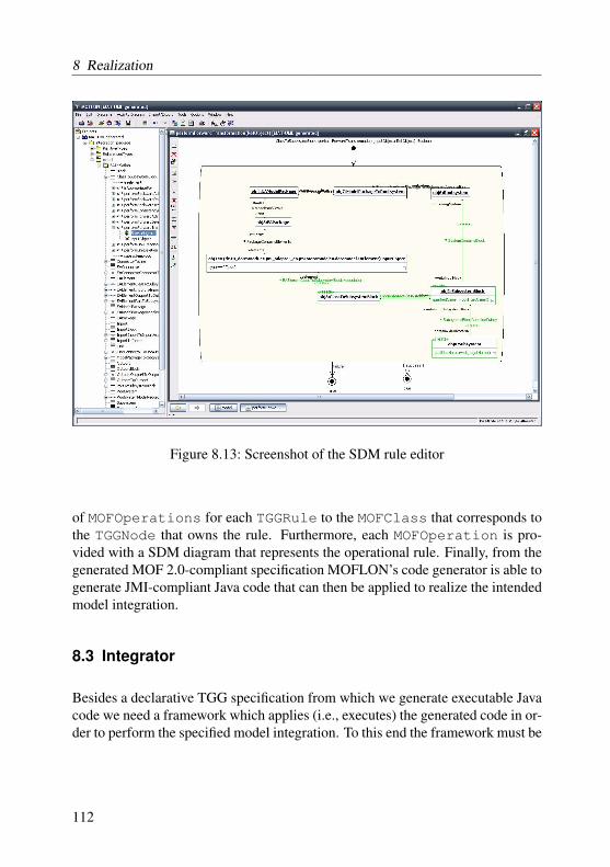
8 Realization
Figure 8.13: Screenshot of the SDM rule editor
of MOFOperations for each TGGRule to the MOFClass that corresponds tothe TGGNode that owns the rule. Furthermore, each MOFOperation is pro-vided with a SDM diagram that represents the operational rule. Finally, from thegenerated MOF 2.0-compliant specification MOFLON’s code generator is able togenerate JMI-compliant Java code that can then be applied to realize the intendedmodel integration.
8.3 Integrator
Besides a declarative TGG specification from which we generate executable Javacode we need a framework which applies (i.e., executes) the generated code in or-der to perform the specified model integration. To this end the framework must be
112

8.3 Integrator
Figure 8.14: Screenshot of the MOFLON-Integrator
able to access the generated code. Furthermore, the framework must be providedwith strategies how to apply the generated code (cf. Section 7.2).
Since the framework must be able to access the generated code we have twopossibilities how to implement such a framework. On the one hand we couldgenerate a dedicated framework for each model integration, which is insepara-bly linked to the code generated from the TGG specification. This is done byapproaches like [Bec08] for instance. On the other hand we could implement ageneric framework that is able to dynamically access the generated model inte-gration code at runtime. Since both possibilities are appropriate and feasible it ismerely a matter of taste. In the end we chose the latter possibility for implement-ing a prototypical model integration framework. The name of the prototype weimplemented simply is MOFLON-Integrator. We emphasize that the MOFLON-Integrator is a component that runs independently from the MOFLON case tool.
Figure 8.14 presents a screenshot of our prototype. In the first row of theMOFLON-Integrator dialog we have to specify the metamodels of the source,the target, and the correspondence models. In the second row we have to spec-ify the source, target, and correspondence models. In the third row we have tochoose whether we want to access the regarded models through the APIs (ap-plication programming interfaces) of the CASE tools that keep the data (onlinemode) or through xmi-exports of the tools’ data (offline mode). In case of the
113

8 Realization
MOF to Java Mapping 39
The root of the inheritance graph is a group of predefined interfaces that make up the Reflectivepackage (see Chapter 5, MOF Reflective Package). These interfaces collectively provide:
n Operations that implement object identity.n Operations that provide introspection.n Operations for exercising the functionality of an object independent of its (metamodel-specific)
generated interface.
Note – The interfaces in the Reflective package are all designed to be “abstract”; i.e. it is notanticipated that they should be the “most derived” type of any metaobject.
The interfaces for the Package objects, Association objects, Class Proxy objects and Instanceobjects provide functionality as described previously. The inheritance patterns are as follows:
n An Instance object that has no supertypes extends RefObject; all other Instance objects extendtheir supertypes.
n A Package object that has no supertypes extends RefPackage; all other Package objects extendtheir supertypes.
n All Class Proxy objects extend RefClass.n All Associations extend RefAssociation.
C2
C1
Package P1
P1 P2
A
Metamodel Definition
C1Class
P2
P1
C2
C1
C2ClassA
RefPackage RefAssociation RefFeatured
RefBaseObject
Inheritance in Generated Interfaces
RefObject RefClass
FIGURE 4-1 Generated Java inheritance patterns.Figure 8.15: Mapping of a MOF model to Java interfaces (taken from [Sun02])
correspondence model the online mode could mean that the correspondence linksare stored in a database instead of a simple xmi-file.
Generally, the offline mode requires jar-files that have been generated by MOF-LON from MOF 2.0-compliant specifications. These jar-files contain JMI4-compliant interfaces [Sun02] and corresponding in-memory implementations. Incase of the online mode these jar-files contain JMI-compliant interfaces as well.Rather than corresponding in-memory implementations these jar-files provideimplementations that map the JMI interfaces to the APIs of the regarded tools.Both variants of jar-files (online or offline) usually provide a reader and a writerin order to (de-)serialize the tools’ data using the XMI5 file format [OMG05a].
Sun’s JMI specification defines a mapping of MOF models to Java interfaces.Figure 8.15 exemplarily illustrates this mapping. On the left-hand side we see
4Java Metadata Interfaces5XML metadata interchange
114
8.3 Integrator
a very simple MOF model. We have two packages P1 and P2. Thereby, P2inherits from P1. Furthermore, P1 contains two classes C1 and C2 that inheritfrom each other and are related to each other by means of an association A. Theright-hand side of the figure depicts the corresponding JMI interfaces. First ofall the JMI specification defines a set of reflective interfaces that are independentfrom the actual metamodel. These interfaces enables users to explore the cor-responding metamodel as well as conforming models without any knowledge ofthe metamodel itself. Furthermore, the JMI specification demands that for a givenmetamodel a number of dedicated interfaces must exist that enable the users toaccess the metamodel and conforming models relying on the actual types that aredefined by the metamodel.
All other JMI interfaces directly or indirectly inherit from the reflective in-terface RefBaseObject. This interface contains operations for querying theidentity of model elements, to determine their meta object and their contain-ing package, and to evaluate constraints attached to them. The RefPackageinterface provides operations for accessing elements (i.e., classes, associations,nested packages that reside in a given package. The operations of the Ref-Association interface enables its users to query and maintain links betweenmodel elements that are based on a given association. Using the operations of theRefFeatured interface a user can utilize the (possibly statical) features (i.e.,attributes and operations) of model elements. Additionally, the RefObjectinterface provides operations to check whether a model element is of a certaintype and to determine the containment hierarchy of model elements by means ofcomposition relationships. Finally, the RefClass interface offers operations toquery the set of model elements of a given type and allows for the creation of newmodel elements.
Besides the reflective interfaces a number of metamodel-dependent interfacesthat extends the reflective interfaces are generated. For each package of the meta-model a corresponding interface P1 and P2 are generated. Similarly, associationA is mapped to a corresponding interface. Finally, for each class C1 and C2 twointerfaces are generated. The interfaces C1 and C2 represent the actual model el-ements whereas the interfaces C1Class and C2Class act as factory interfacesthat additionally keep track on the set of model elements of the regarded type.These factory interfaces are called proxies in the JMI specification.
Our generic model integration framework heavily relies on the reflective JMIinterfaces since the framework should be kept independent from the actual meta-models of the to be integrated models. In contrast the code generated from the
115

8 Realization
declarative TGG rules relies on the typed JMI interfaces as the rules are only validfor the metamodels chosen at specification time anyway.
The fourth row of Figure 8.14 contains a button for invoking the Linkbrowserof the MOFLON-Integrator as explained in the following section. Furthermore,there is a combo box that allows the users to choose the model integration taskthey want to perform. Currently, only the forward model transformation task isprototypically implemented. The implementation of the remaining integrationtasks is straight-forward and will be include in the next version of the MOFLON-Integrator. Finally, the Go-button invokes the chosen model integration taskwhich results in the application of the appropriate model integration rules ac-cording to the rule application strategy as explained in Section 7.2. The last rowof the MOFLON-Integrator dialog is used to display information on the currentlyrunning integration task.
8.4 Linkbrowser
Besides the fact that correspondence links are maintained in order to realize modelintegration the users want to be able to inspect existing correspondences for trace-ability purposes. In fact the visualization of correspondence links is one of themain purposes of the Toolnet framework as mentioned in Section 9.1. Since incommon software and system development projects the number of involved mod-els, model elements, and correspondences is large the question arises how to ap-propriately display their relationships. In [FK03] we identified the following usecases that should be addressed by a visualization component.
1. The user wants to get a complete overview of a considered project. Inparticular, this is important for project managers which have to coordinatedevelopment teams, monitor the project’s progress, and plan the next steps.
2. A pair of developers is working on a certain aspect of a system and wantto discuss problems at a very fine-grained level of abstraction. Therefore,they need to inspect the correspondences at the level of model elements.
3. A user modifies a part of a considered system and wants to predict theimpact of his modifications to the rest of the whole system.
4. Users want to maintain correspondence links using one component thatallows to access all links of the considered project.
116

8.4 Linkbrowser
The solution we presented in [FK03] was based on XML Topic Maps6 and re-lied on the Touchgraph7 framework. Topic Maps as defined by the ISO/IEC 13250Topic Maps standard8 are designed for describing large knowledge structures. Thebasic concepts are typed Topics and typed Associations that relate topics with eachother. The mapping of model elements to topics and correspondence links to as-sociations is obvious and straight-forward. We used the Touchgraph framework tovisualize Topic Maps. The Touchgraph framework displayed the model elementsand correspondence links in a so-called hyperbolic manner. This means that alimited number of model elements and their correspondences are in the focus ofthe visualization. These elements are displayed in detail. The remaining elementsare displayed in a more abstract and vague way at the border of the visualizationarea. The user is able to shift the focus by navigating along the correspondencelinks. Thus, the proposed solution addressed the use cases 1, 2, and 3. In [FK03]we did not address Use Case 4. Although the use of a hyperbolic view seemed tobe a good idea at first glance practice has shown that in fact this kind of view isnot very convenient as the user can explore the direct neighborhood of a modelelement and its attached traceability links only. The user is not provided with anoverview of all existing traceability links.
Therefore, we propose another visualization component based on Fraunhofer’sMatrixbrowser9. Basically, the Matrixbrowser is used to visualize a number ofelements called nodes and links between them called relations. The elements arestored in a tree structure as illustrated on the left-hand side of Figure 8.16. Thelinks are visualized in a matrix as shown on the right-hand side of Figure 8.16.To this end one subtree is displayed vertically, a second is displayed horizontally.Links are depicted as circles in the matrix that are connected to the linked ele-ments by arrows. Using drag and drop the user is enabled to arbitrarily choosesubtrees he wants to inspect. Particularly, the user may choose to select the entiretree for both vertical and horizontal display. Although the resulting matrix is largeit contains all links that exist between elements of the tree. Obviously, we mapmodel elements to nodes while correspondence links are mapped to relations. Inorder to construct the needed tree structure we create a root node which repre-sents the considered project as a whole. Attached to this root node we have nodesthat represent all relevant data sources of the project. Each data source node is
6http://www.topicmaps.org/xtm/7http://www.touchgraph.com8http://topicmaps.org/xtm/index.html9http://matrixbrowser.hci.iao.fraunhofer.de/en/
117

8 Realization
Figure 8.16: Screenshot of the Matrixbrowser
then attached with the hierarchy (by means of composition relationships) of itscontained model elements. Now the user is enabled to select arbitrary parts of aproject (e.g. the whole project, single data sources, parts of data sources) in orderto inspect existing correspondence links.
For enhancing the expressive power of the visualization we added the fol-lowing modifications to the Matrixbrowser. The resulting component is calledLinkbrowser.
1. The background color of nodes can be changed. For instance this allowsto display consistency information for each model element (e.g., green sig-nals a consistent model element, red signals an inconsistent model element,yellow means that it is unknown whether a model element is consistent).
2. The color of relations can be changed. Correspondingly, this allows todisplay consistency information for each correspondence links using thesame color schema as above.
3. Nodes and relations can be attached with context menus. This allows forinvoking model integration rules on single model elements and correspon-dence links. For instance the consistency of a correspondence link whichconsistency status is yet unknown can be (re-)calculated.
118

8.4 Linkbrowser
4. The tooltips of nodes and relations can be modified. This allows for dis-playing additional information on each model element and correspondencelink.
5. It is possible to replace the circles that represent correspondence links inthe matrix by arbitrary graphical elements. This is useful when crucialinformation on a correspondence link should be displayed in the matrix.
6. Finally, a problem panel as inspired by the problem panel of the Java De-velopment Toolkit of the Eclipse framework has been added. In this panelfurther information a consistency violation is listed. When the user clickson an entry of this list the concerned model element or correspondence linkis selected from the matrix.
Currently, the features listed above are only included as part of the ToolNet frame-work. It is ongoing work to transfer these features to the Linkbrowser of theMOFLON-Integrator. The Linkbrowser has proved to be useful for cases wherethe user wants to inspect correspondence links of two parts of a project. It is anopen issue to provide an appropriate support for navigating along existing cor-respondence links between various parts of a project (e.g., navigation from a re-quirement, to its corresponding specification, to its corresponding realization, toits corresponding test case).
119

9 Application
In this chapter we present the application of our approach to the use cases identi-fied in Chapter 1.3. Particularly, we demonstrate the traceability link creation andmodel-model consistency analysis in the context of the ToolNet project [ADS02].Furthermore, we present the transformation of an Enterprise Architect1 modelinto a Matlab/Simulink2 model. The entire set of TGG rules concerning our run-ning example from Section 3.1 can be found in Appendix A.
9.1 The ToolNet project
ToolNet [ADS02] has been developed by DaimlerChrysler in cooperation withthe universities of Berlin, Paderborn, and Darmstadt. Currently, ToolNet is dis-tributed as a product by Extessy3. The aim of ToolNet is to provide a tool integra-tion platform. Thereby, tool integration means relating model elements which arekept in an arbitrary number of commercial off the shelf (COTS) tools with eachother by means of traceability links.
To this end ToolNet offers a Java-based framework for implementing tooladapters. Each ToolNet tool adapter conforms to the proprietary ToolNet tooladapter interface. On the one hand this interface defines a number of user inter-face and tool management related operations such as highlight a certain objectwhich is used to focus on model elements that are linked with each other, markedlinked objects which marks all model elements of a given tool that are linked withother model elements of different tools by traceability links, or start and stop acertain tool. On the other hand this interface defines basic read-only operationsfor accessing the model data stored in the adapted tool similar to but not as com-plete as the read-only operations defined by the JMI standard as introduced inthe preceding chapter. Moreover, ToolNet provides a component called ToolNet
1http://www.sparxsystems.de/2http://www.mathworks.com/3http://www.extessy.com/
120

9.1 The ToolNet project
Figure 9.1: Screenshot of the ToolNet desktop
Desktop which is a central visual component that allows the user to invoke toolintegration related operations such as start or stop a certain tool, query for ex-isting traceability links, calculate the model elements that are linked to a givenmodel element, and so on. Figure 9.1 shows a screenshot of the ToolNet Desk-top. Finally, ToolNet has a database called Relation Repository for maintainingcreated traceability links. Note that ToolNet rather than other tool integration sce-narios only stores traceability link information in a (central) database. The modelelements created with the adapted tools remain in their tool repositories.
One of our contributions to ToolNet is a component called Automatic Link Cre-ation. This component utilizes Java code that has been generated from operationalCorrespondence link creation rules as introduced in Chapter 7. To recall, theseoperational rules are derived from a corresponding declarative TGG rule as in-troduced in Chapter 6. The Automatic Link Creation component enables ToolNet
121
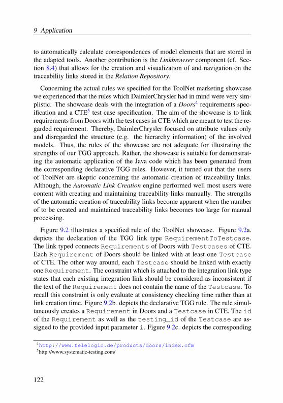
9 Application
to automatically calculate correspondences of model elements that are stored inthe adapted tools. Another contribution is the Linkbrowser component (cf. Sec-tion 8.4) that allows for the creation and visualization of and navigation on thetraceability links stored in the Relation Repository.
Concerning the actual rules we specified for the ToolNet marketing showcasewe experienced that the rules which DaimlerChrysler had in mind were very sim-plistic. The showcase deals with the integration of a Doors4 requirements spec-ification and a CTE5 test case specification. The aim of the showcase is to linkrequirements from Doors with the test cases in CTE which are meant to test the re-garded requirement. Thereby, DaimlerChrysler focused on attribute values onlyand disregarded the structure (e.g. the hierarchy information) of the involvedmodels. Thus, the rules of the showcase are not adequate for illustrating thestrengths of our TGG approach. Rather, the showcase is suitable for demonstrat-ing the automatic application of the Java code which has been generated fromthe corresponding declarative TGG rules. However, it turned out that the usersof ToolNet are skeptic concerning the automatic creation of traceability links.Although, the Automatic Link Creation engine performed well most users werecontent with creating and maintaining traceability links manually. The strengthsof the automatic creation of traceability links become apparent when the numberof to be created and maintained traceability links becomes too large for manualprocessing.
Figure 9.2 illustrates a specified rule of the ToolNet showcase. Figure 9.2a.depicts the declaration of the TGG link type RequirementToTestcase.The link typed connects Requirements of Doors with Testcases of CTE.Each Requirement of Doors should be linked with at least one Testcaseof CTE. The other way around, each Testcase should be linked with exactlyone Requirement. The constraint which is attached to the integration link typestates that each existing integration link should be considered as inconsistent ifthe text of the Requirement does not contain the name of the Testcase. Torecall this constraint is only evaluate at consistency checking time rather than atlink creation time. Figure 9.2b. depicts the declarative TGG rule. The rule simul-taneously creates a Requirement in Doors and a Testcase in CTE. The idof the Requirement as well as the testing_id of the Testcase are as-signed to the provided input parameter i. Figure 9.2c. depicts the corresponding
4http://www.telelogic.de/products/doors/index.cfm5http://www.systematic-testing.com/
122
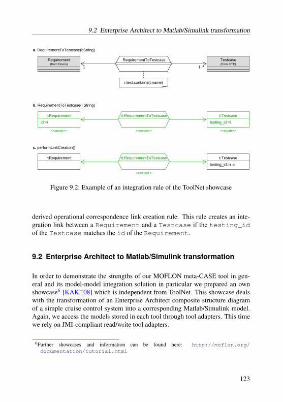
9.2 Enterprise Architect to Matlab/Simulink transformation
r:Requirement t:Testcasert:RequirementToTestcase
<<create>> <<create>> <<create>>
b. RequirementToTestcase(i:String)
id:=i testing_id:=i
Requirement(from Doors)
Testcase(from CTE)
RequirementToTestcase
1 1..*
r.text.contains(t.name)
r:Requirement t:Testcasert:RequirementToTestcase
<<create>>
c. performLinkCreation()
testing_id:=r.id
a. RequirementToTestcase(i:String)
Figure 9.2: Example of an integration rule of the ToolNet showcase
derived operational correspondence link creation rule. This rule creates an inte-gration link between a Requirement and a Testcase if the testing_idof the Testcase matches the id of the Requirement.
9.2 Enterprise Architect to Matlab/Simulink transformation
In order to demonstrate the strengths of our MOFLON meta-CASE tool in gen-eral and its model-model integration solution in particular we prepared an ownshowcase6 [KAK+08] which is independent from ToolNet. This showcase dealswith the transformation of an Enterprise Architect composite structure diagramof a simple cruise control system into a corresponding Matlab/Simulink model.Again, we access the models stored in each tool through tool adapters. This timewe rely on JMI-compliant read/write tool adapters.
6Further showcases and information can be found here: http://moflon.org/documentation/tutorial.html
123

9 Application
EAModelPackage
EAPackage
views
model0..1
*
EAElement
name : Stringtype : Stringstereotype : String
package
elements
0..1
*
EAConnector
type : String
supplier
client
supplierConnectorclientConnector
11
0..*
0..*
element
element
*
0..1
ea
Figure 9.3: Simplified metamodel of Enterprise Architect
Figure 9.3 depicts a simplified metamodel of Enterprise Architect. Basi-cally, an Enterprise Architect model is contained in an EAModelPackage. AnEAModelPackage is provided with a number of EAPackage which representviews of the model. Among others each EAPackage contains a number ofEAElements which have names, types, and stereotypes. Thereby, thevalues of type and stereotype determine which actual (UML) element ismeant and how it is graphically represented. For instance an outport is representedas an EAElementwhich type is Port and which stereotype is Outport.Each EAElement may contain further EAElements. Finally, EAElementscan be connected to each other by typed EAConnectors. The source of anEAConnector is called supplier; the target is called client.
124

9.2 Enterprise Architect to Matlab/Simulink transformation
System
Rootsystem Subsystem Block
SubsystemBlock InportBlock OutportBlock
Port
Inport Outport
Line
containingSystem
containedBlock
containingSubsystem
containedSubsystemBlock
1
*
1
*
block
1
ports
*
correspondingInportBlock 0..1
correspondingInport
0..1
1
correspondingOutportBlock 0..1
correspondingOutport 1
Inport
targetLine
1
Outport
1
0..1
sourceLine
simulink
Figure 9.4: Simplified metamodel of Matlab / Simulink
Figure 9.4 depicts a simplified metamodel of Matlab / Simulink. The reader isadvised that each element of a Matlab / Simulink model carries a qualifiedname. Basically, a Matlab / Simulink models consists of a Rootsystem and anumber of Subsystems. A System (i.e., Rootsystems and Subsystems)contains Blocks (i.e., SubsystemBlocks, InportBlocks, and Out-portBlocks). Subsystems can be provided with Inports and Outportswhich correspond to the InportBlocks and OutportBlocks. Finally,Outports can be connected to Inports by Lines.
Based on the metamodels presented in Figure 9.3 and Figure 9.4 we comeup with the metamodel of our model integration specification (cf. Figure 9.5).We have declared the integration link types ModelPackageToRootsystem,ClassToSubsystemBlock, PartToSubsystemBlock, InportToIn-port, OutportToOutport, and ConnectorToLine. The integration linktypes ClassToSubsystemBlock, InportToInport, and OutportTo-
125

9 Application
EAModelPackage Rootsystem
SubsystemBlock
Inport
Outport
Line
EAElement
Connector
0 ModelPackageToRootsystem
ModelPackageToRootsystem()
0 ClassToSubsystemBlock
ClassToSubsystemBlock(n:String)
0 PartToSubsystemBlock
PartToSubsystemBlock()
0 InportToInport
InportToInport(n:String)
0 OutportToOutport
OutportToOutport(n:String)
0 ConnectorToLine
ConnectorToLine()
1 1
11
1
1
0..10..1
0..1
0..1
0..1
0..1
integration
Figure 9.5: Integration metamodel
Outport are parametrized, whereas the remaining integration link types arenot. Basically, each model element of Enterprise Architect will be linked toone model element of Matlab/Simulink. The multiplicity {0..1} indicatesexclusive or7. That means that an EAElement will be integrated either witha SubsystemBlock, an Inport, or an Outport. Correspondingly, eachSubsystemBlock will be integrated with a EAElement either by a Class-ToSubsystemBlock link or a PartToSubsystemBlock link. All declaredintegration link types are provided with a priority of 0. As we will see below thepatterns of the TGG rules attached to each integration link type ensure that the
7Upcoming versions of our TGG editor should provide a syntactic construct for expressing exclusiveor.
126

9.2 Enterprise Architect to Matlab/Simulink transformation
mp:EAModelPackage r:Rootsystemmpr:ModelPackageToRootsystem
p:EAPackage
model
views
<<create>> <<create>> <<create>>
<<create>>
mp r:Rootsystemmpr:ModelPackageToRootsystem
p:EAPackage
model
views
<<create>> <<create>>
<<create>>
a. ModelPackageToRootsystem()
b. performForwardTransformation(mp:EAModelPackage)
Figure 9.6: ModelPackageToRootsystem rule
rules do not conflict with each other (i.e., for each regarded model element atmost one rule will be applicable for).
Figure 9.6a. shows the declarative TGG rule of the link integration typeModelPackageToRootsystem. The rule has no input parameters and meansthat the elements mp in Enterprise Architect and r in Matlab/Simulink are createdsimultaneously. Furthermore, these elements are linked to each other by a newintegration link mpr. Finally, a secondary element p is created in Enterprise Ar-chitect.
Figure 9.6b. shows the operational forward transformation rule which has beenderived from the declarative TGG rule in Figure 9.6a. This time the element mpris provided as an input parameter to the rule. The rule creates a new element r inMatlab/Simulink and links it to mp by a new integration link mpr if an element pin Enterprise Architect exists which is attached to mp.
127
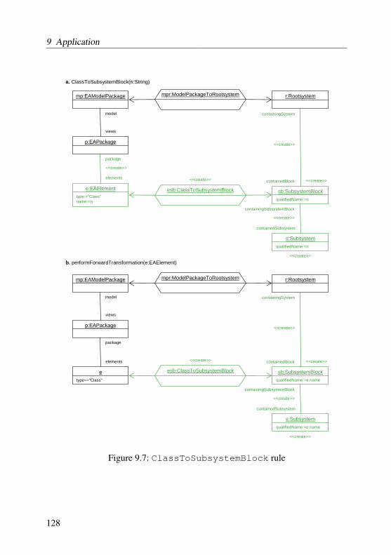
9 Application
mp:EAModelPackage r:Rootsystemmpr:ModelPackageToRootsystem
p:EAPackage
model
views
a. ClassToSubsystemBlock(n:String)
e:EAElement
package
elements
type:="Class"name:=n
sb:SubsystemBlockqualifiedName:=n
esb:ClassToSubsystemBlock
s:SubsystemqualifiedName:=n
containingSystem
containedBlock
containingSubsystemBlock
<<create>>
<<create>>
<<create>>
containedSubsystem
mp:EAModelPackage r:Rootsystemmpr:ModelPackageToRootsystem
p:EAPackage
model
views
b. performForwardTransformation(e:EAElement)
e
package
elements
type=="Class"
sb:SubsystemBlockqualifiedName:=e.name
esb:ClassToSubsystemBlock
s:SubsystemqualifiedName:=e.name
containingSystem
containedBlock
containingSubsystemBlock
<<create>>
<<create>>
containedSubsystem
<<create>>
<<create>>
<<create>>
<<create>> <<create>>
<<create>>
Figure 9.7: ClassToSubsystemBlock rule
128

9.2 Enterprise Architect to Matlab/Simulink transformation
Figure 9.7a. depicts the declarative TGG rule of the link integration typeClassToSubsystemBlock. The rule is provided with an input parametern. The rule simultaneously attaches an element e to an existing element p in En-terprise Architect and an element sb to an existing element r in Matalb/Simulinkand links them with each other by a new integration link esb. Furthermore, therule creates a secondary element s in Matlab/Simulink and attaches it to sb. Thisoccurs only if p is attached to an element mp which is linked by an integrationlink mpr to element r.
Again, Figure 9.7b. depicts the corresponding operational forward transforma-tion rule. This rule is provided with an input parameter e. The rule attaches anew element sb to an element r and links it to e by a new intergation link esb.Furthermore, the rule creates a new element s and attaches it to sb. This occursonly if e is attached to an element p which in turn is attached to an element mp.Moreover, mp has to be linked to r by an integration link mpr.
Figure 9.8a. presents the declarative TGG rule of the link type PartToSub-systemBlock. This rule does not have any input parameters. The rule simul-taneously creates a new element e2 and a new secondary element c in EnterpriseArchitect as well as a new connection between element s and sb2. Furthermore,the rule creates a new integration link psb which links e2 and sb2. This ruleis a special case because it does not create a new element in Matlab/Simulink.Rather, it adds a new connection between two already existing elements in Mat-lab/Simulink only. Additionally, the created integration link also refers to an al-ready existing element in Matlab/Simulink.
The corresponding operational forward transformation rule is presented in Fig-ure 9.8b. This rule links the provided element e2 with the already existing ele-ment sb2 by a new intergation link psb. Thereby, sb2 has to be already linkedto an element e3 on which e2 depends on. Furthermore, the rule attaches sb2 tothe element s which is contained in an element sb1 that is linked to the elemente1 to which e2 is attached to.
The declarative TGG rule of link type InportToInport is shown in fig-ure 9.9a8. The rule simultaneously adds an element e2 of the type Port andthe stereotype Inport to Enterprise Architect as well as an element i to Mat-lab/Simulink. Furthermore, e2 and i are linked by a new integration link ii.Finally, the rule adds a secondary element ib to Matlab/Simulink which corre-spondes to i and is attached to an element s. Thereby, s is contained in element
8The rule of link type OutportToOutport looks nearly identical.
129

9 Application
e1:EAElement sb1:SubsystemBlockesb1:ClassToSubsystemBlock
a. PartToSubsystemBlock()
type=="Class"
e2:EAElementtype:="Part"
c:EAConnectortype:="Dependency"
e3:EAElementtype=="Class"
s:Subsystem
sb2:SubsystemBlockpsb:PartToSubsystemBlock
esb2:ClassToSubsystemBlock
element
elements
client
connectorClient
connectorSupplier
supplier
containingSubsystemBlock
containedSubsystem
containingSystem
containedBlock
<<create>>
<<create>>
<<create>>
<<create>>
<<create>>
<<create>>
<<create>>
e1:EAElement sb1:SubsystemBlockesb1:ClassToSubsystemBlock
b. performForwardTransformation(e2:EAElement)
type=="Class"
e2type=="Part"
c:EAConnectortype=="Dependency"
e3:EAElementtype=="Class"
s:Subsystem
sb2:SubsystemBlockpsb:PartToSubsystemBlock
esb2:ClassToSubsystemBlock
element
elements
client
connectorClient
connectorSupplier
supplier
containingSubsystemBlock
containedSubsystem
containingSystem
containedBlock
<<create>>
<<create>>
Figure 9.8: PartToSubsystemBlock rule
130
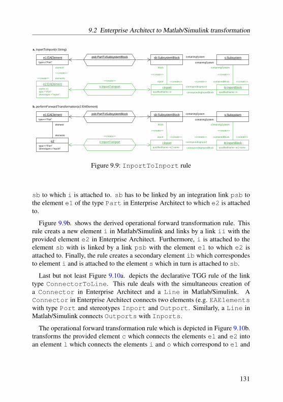
9.2 Enterprise Architect to Matlab/Simulink transformation
e1:EAElement sb:SubsystemBlockpsb:PartToSubsystemBlock
a. InportToInport(n:String)
type=="Part"
s:Subsystem
i:Inport ib:InportBlockii:InportToInporte2:EAElement
qualifiedName:=n qualifiedName:=nname:=ntype:="Port"stereotype:="Inport"
element
elements
block
inport
containingSystem
containedBlock
containingSystem
containingSystem
correspondingInport
correspondingInportBlock
<<create>> <<create>> <<create>><<create>>
<<create>> <<create>> <<create>><<create>>
e1:EAElement sb:SubsystemBlockpsb:PartToSubsystemBlock
b. performForwardTransformation(e2:EAElement)
type=="Part"
s:Subsystem
i:Inport ib:InportBlockii:InportToInporte2
qualifiedName:=e2.name qualifiedName:=e2.nametype=="Port"stereotype=="Inport"
element
elements
block
inport
containingSystem
containedBlock
containingSystem
containingSystem
correspondingInport
correspondingInportBlock
<<create>> <<create>>
<<create>> <<create>> <<create>><<create>>
Figure 9.9: InportToInport rule
sb to which i is attached to. sb has to be linked by an integration link psb tothe element e1 of the type Part in Enterprise Architect to which e2 is attachedto.
Figure 9.9b. shows the derived operational forward transformation rule. Thisrule creats a new element i in Matlab/Simulink and links by a link ii with theprovided element e2 in Enterprise Architect. Furthermore, i is attached to theelement sb with is linked by a link psb with the element e1 to which e2 isattached to. Finally, the rule creates a secondary element ib which correspondesto element i and is attached to the element s which in turn is attached to sb.
Last but not least Figure 9.10a. depicts the declarative TGG rule of the linktype ConnectorToLine. This rule deals with the simultaneous creation ofa Connector in Enterprise Architect and a Line in Matlab/Simulink. AConnector in Enterprise Architect connects two elements (e.g. EAElementswith type Port and stereotypes Inport and Outport. Similarly, a Line inMatlab/Simulink connects Outports with Inports.
The operational forward transformation rule which is depicted in Figure 9.10b.transforms the provided element c which connects the elements e1 and e2 intoan element l which connects the elements i and o which correspond to e1 and
131

9 Application
e1:EAElement i:Inportii:InportToInport
a. ConnectorToLine()
type=="Port"stereotype=="Inport"
b1:Block
l:Line s:Systemcl:ConnectorToLinec:EAConnectortype:="Connector"
client
connectorClient
inport
targetLine
containedBlock
containingSystem
inport
block
containedLine
containingSystem
<<create>> <<create>>
<<create>> <<create>> <<create>> <<create>>
e2:EAElement o:Outportoo:OutportToOutporttype=="Port"stereotype=="Outport"
b2:Blockoutport
block
containingSystem
containedBlock
sourceLine
outport
<<create>>
connectorSupplier
supplier
<<create>>
e1:EAElement i:Inportii:InportToInport
b. performForwardTransformation(c:EAConnector)
type=="Port"stereotype=="Inport"
b1:Block
l:Line s:Systemcl:ConnectorToLinectype=="Connector"
client
connectorClient
inport
targetLine
containedBlock
containingSystem
inport
block
containedLine
containingSystem
<<create>>
<<create>> <<create>> <<create>>
e2:EAElement o:Outportoo:OutportToOutporttype=="Port"stereotype=="Outport"
b2:Blockoutport
block
containingSystem
containedBlock
sourceLine
outport
<<create>>
connectorSupplier
supplier
Figure 9.10: ConnectorToLine rule
e2 respectively. Thereby, l will be attached to the element s which owns theelements b1 and b2 which are attached to i and o respectively.
132

10 Related work
In this chapter we compare our model integration approach with various relatedapproaches in order to discuss strengths and flaws. To this end we come up with anumber of categorization criteria we use to benchmark all approaches. We beginour benchmark with the discussion of approaches that deal with model integrationin general but use entirely different approaches than we do. We then continuewith approaches that directly utilize operational graph grammars. After that weexamine related triple graph grammar approaches that yet usually do not aimat compliance to the QVT standard. Finally, we evaluate approaches that aimat compliance to (parts of) the QVT standard but do not utilize (triple) graphgrammars.
10.1 Categorization criteria
In order to compare the different approaches with each other we evaluate to whichextend the criteria provided by the QVT-RFP as outlined in Section 3.2 have beenimplemented. Since only QVT-based approaches intentionally aim at complianceto the QVT requirements it would not be surprising when the other approaches donot adhere to these requirements. Therefore, only using the criteria provided bythe QVT-RFP does not appear to be fair.
[CH03] provides a more objective and overarching set of criteria which can beused to evaluate any model transformation approach independently from the QVTstandard. At top-level [CH03] considers the following categories: TransformationRules, Rule Application Scoping, Source-Target Relationship, Rule ApplicationStrategy, Rule Application Strategy, Rule Scheduling, Rule Organization, Tracing,and Directionality.
Transformation Rules
This category examines in which way model transformation rules are writtendown in a considered approach. [CH03] assumes that rules are composed of a
133

10 Related work
left-hand and a right-hand side. In contrast to graph rewriting systems where theleft-hand side of a rule refers to the part of a rule that has to be matched in thehost graph and the right-hand side designates the modification to the host graph[CH03] appoints that the left-hand side (LHS) refers to the source model and theright-hand side (RHS) refers to the target model. However, LHS and RHS maybe provided with patterns or logic expressions. Patterns can be written as strings,terms, or graphs. The syntax in which patterns are written down can meet theabstract or the concrete syntax in which source and target models are written in.Elements of the patterns can be typed or untyped. Logic expressions can be ex-ecutable (imperatively or declaratively) or non-executable. Additionally, patternscan involve (typed or untyped) variables.
Rules can contain the LHS and the RHS separately or in a collapsed style. Fur-thermore, rules may be executable bidirectionally or unidirectionally only. Rulesmight be parameterizable or nor. Some approaches need to construct intermediatestructures that neither belong to the source nor to the target model and usually aredropped at the end of the model transformation.
Rule Application Scoping
This category distinguishes whether the scope of a model transformation can bereduced with respect to the source and the target model (i.e., only parts of themodels are considered).
Source-Target Relationship
This category discusses in which way a target model is constructed from a givensource model. Each model transformation approach usually is able to create anew target model from a source model (i.e., a batch transformation). In additionan approach may be able to modify an already existing target model (i.e., anincremental transformation). The case where source and target model coincideis called an in-place transformation. If an approach is able to modify an existingtarget model [CH03] distinguishes whether the transformation may only extendthe target model or additionally may delete existing elements.
134

10.1 Categorization criteria
Rule Application Strategy
Usually there are multiple locations in the source model to which a given rule canbe applied to. The transformation needs to select the locations to which the ruleactually should be applied to. Basically, the algorithm to select these locationscan be deterministic, non-deterministic, or interactive.
Rule Scheduling
This category introduces criteria concerning the order in which the transforma-tion rules are applied. First of all, the scheduling of rules is implicit or explicit.Implicit rule scheduling means that the user has no means to directly influence theorder in which rules are applied. In contrast explicit rule scheduling means thatthe user is able to directly influence this order. Explicit rule scheduling is calledexternal if the approach provides control structures that are clearly separated fromthe rules. Explicit rule scheduling is called internal if the approach allows rulesto directly invoke other rules.
Furthermore, the transformation algorithm needs a strategy to select a rule thatis to be applied next. Again this strategy can be deterministic, non-deterministic,or interactive. Additionally, the strategy needs to be able to resolve conflicts (i.e.,multiple rules are applicable at the same time).
Moreover, an approach might be able to apply rules iteratively, recursively, orbased on fixpoint iteration. Finally, the transformation process may be subdividedinto several distinct phases (e.g. transform the structure of the source model first,deal with the attribute values after).
Rule Organization
This category discusses in which ways a set of rule can be organized. This in-cludes means for modularization (i.e., package concepts) and reusability (i.e.,inheritance and rule composition). Finally, the set of rules can be organized ac-cording either to the structure of the source or the target model, or independentlyfrom them.
135

10 Related work
Tracing
Approaches may provide dedicated support for traceability links (i.e., links thatmaterialize the dependencies between source and target model elements). [CH03]distinguishes approaches that store traceability links either in the source or thetarget model, or separately from them. Furthermore, the creation of rules can becontrolled either manually or automatically for all or just for some rules.
Directionality
The last category deals with the direction in which a set of rules is applicable.Rules of unidirectional approaches can only be applied from source to target.These approaches need an entirely new set of rules for performing a transforma-tion in the reverse direction. In contrast bidirectional approaches can apply oneset of rules in both directions. Either the rules themselves are applicable in bothdirections or the set of rules contains complementary unidirectional rules1.
10.2 Common approaches
In this section we examine common (model) integration approaches that use anentirely different approach or have a different focus than we do. Particularly, wediscuss data warehouses, federated databases, and enterprise application integra-tion solutions.
Data Warehouses
Basically, a data warehouse [KR02] is a database to which data from operationalsystems is propagated to in order to perform time consuming integrated analy-sis on the data. When the data is available at the database the desired analysiscan be expressed using the query language of the database. The challenge is tocreate a database schema that is capable of storing the data of all considered op-erational systems. Usually, every time a new system is added the schema of thedata warehouse has to be adjusted. On the one hand this task is very intricate,on the other hand the task becomes even harder when the number of operationalsystems grows.
1The author is the opinion that such approaches should not be considered bidirectional.
136

10.2 Common approaches
Federated Databases
In a federated database system [HM85] a component called mediator is used toaccess a number of databases of operational systems through one common inter-face. For a client it looks like it is accessing one integrated database. In orderto calculate the result of a query the mediator needs to decompose the query intosubqueries that are to be performed on each affected database. The results of eachsubquery need to be merged by the mediator in order to provide the result of theactual query. As pointed out in [Zha94] one crucial point in federated databasesis the coordination or integration of the schemas of the regarded databases intoone common database schema. Thus, federated database systems suffer from thesame problems as data warehouses do.
Enterprise Application Integration
Enterprise Application Integration (EAI) [Gab02] deals with the integration ofheterogeneous applications by connecting them with each other by means ofadapters. Thereby, integration can happen on different levels such as data level,process level, or user-interface level. Furthermore, there are at least three pos-sibilities of how to connect applications to each other. First of all, applicationscan be connected to each other point-to-point. Secondly, applications can be con-nected to each other in a hub-and-spoke architecture. Finally, applications can beconnected to a common application integration bus (e.g. SAP Netweaver2). Inorder to avoid that each application must transform its data into the format of ev-ery other connected application, usually a common data exchange format (i.e., aschema in terms of database systems) is defined. Therefore, EAI approaches suf-fer from the same problems as data warehouses and federated database systemsdo.
As data warehouse solutions, federated database, or EAI solutions usually arerealized by manually implementing the desired integration aspects neither the re-quirements of the QVT-RFP nor the categorization criteria from Section 10.1 canreasonably be applied. Furthermore, the manual implementation of a model in-tegration cannot be regarded as a model integration approach at all. Rather, wesuggest the application of model integration approach such as QVT or TGGs asintroduced in this work.
2http://www.sap.com/platform/netweaver/index.epx
137

10 Related work
10.3 Graph Grammar-based approaches
The approaches presented in this section rely on graph grammars respectivelygraph transformations as introduced in Chapter 4. Our own approach uses graphtransformations as an intermediate language between specification and executablecode as pointed out in Chapter 7.
Among others PROGRES [Sch91], FUJABA [Zün01], MOFLON3 [Ame08],AGG [TB94], and GReAT [BNvBK06] are typical representatives of graph gram-mar / transformation-based systems. AToM3 [dLV02] utilizes graph transforma-tions for the definition of views.
Concerning the categorization we focus on MOFLON as a representative ofgraph grammar / transformation-based systems where suitable as it is designedto meet OMG’s world of meta modeling. Regarding the general requirements ofOMG’s QVT-RFP (cf. Section 3.2) we state that MOFLON’s schema part of agraph transformation specification relies on the MOF 2.0 metamodel. However,the rule part is adopted from the underlying FUJABA system. FUJABA entirelyrelies on a UML 1.x-like metamodel. On the one hand we have discovered thatthe impact of the new MOF 2.0 features on the rule level are negligible [Ame08].On the other hand there are plans to merge FUJABA and MOFLON and relyingon MOF 2.0 as the underlying metamodel for rules as well.
Considering the mandatory requirements of OMG’s QVT-RFP we see that theleft-hand sides of graph transformations rules act as queries whereas the right-hand sides express the modifications (i.e., transformations). Altogether, graphtransformations are suitable for expressing queries, views, and transformations.As already mentioned above their drawbacks are that queries, views, and trans-formations have to be expressed operationally rather than declaratively. Further-more, it is not possible to explicitly keep source, target, and tracing model sepa-rate from each other. In principle it is possible to realize incremental model trans-formations with graph transformations. However, it is a matter of the utilized ruleexecution engine.
With respect to the optional requirement of OMG’s QVT-RFP we point out thatgraph transformations cannot be used to express bidirectional model transforma-tions. Rather, each direction has to be specified explicitly. Moreover, MOFLON
3disregarding our TGG implementation
138

10.4 TGG-based approaches
incorporates a number of concepts for reusing and extending existing model trans-formations [Ame08]. Finally, graph transformations are suitable for expressingin-place model transformations; in fact they are designed for this purpose.
Looking at the categorization criteria of [CH03] we additionally find that graphtransformations do not separate the left-hand side (i.e., the source model in termsof [CH03]) from the right-hand side (i.e., the target model in terms of [CH03]).Usually, graph transformations rely on parametrized graph patterns which canbe assigned with executable logic expressions. To the best of our knowledgeno graph transformation system offers the possibility to reduce the scope of agraph transformation. As graph transformations do not explicitly support theseparation of source and target models they actually realize in-place transforma-tions only. Depending on the regarded graph transformation system any type ofrule application strategy can be supported. Systems as PROGRES or FUJABA/ MOFLON usually rely on a non-deterministic rule application strategy. Simi-larly, graph transformation systems realizes any type of rule scheduling. Usually,graph transformation systems (particularly PROGRES and MOFLON) providemeans for rule organization as package concepts and means for reusing existinggraph transformations. Graph transformation systems are capable of supportingtraceability links provided that they are explicitly modeled and regarded as partof the in-place transformation. Thus, traceability links are not separated from thesource and target model parts. Finally, graph transformation rules are applica-ble in one direction only. If the other direction is needed it has to be specifiedexplicitly and is not derived automatically.
10.4 TGG-based approaches
The approaches presented in this section rely on the initial idea of triple graphgrammars as pointed out in Section 4.5. Particularly, we focus on the approachesof [Bec08], [Wag08], and [GK07]. Our own approach belongs the the categoryof these approaches. However, for categorization purposes we disregard our ownapproach for a moment in order to be able to emphasize the contributions of ourapproach.
Concerning the general requirements of OMG’s QVT-RFP we find that noneof the currently available TGG approaches conforms to the MOF 2.0 standard.For writing TGG rules [Bec08] relies on a UML / MOF 1.4 metamodel which hasbeen extended by own concepts. From the specified TGG rules [Bec08] derives
139
10 Related work
a PROGRES specification which contains the corresponding operational rules.PROGRES itself does not conform to any of the OMG standards. [Wag08] and[GK07] rely on FUJABA for the creation of TGG specifications. For each declar-ative specification [Wag08] and [GK07] derive another FUJABA specificationwhich contains the operational rules. FUJABA’s metamodel conforms more orless to the UML 1.x metamodel.
Regarding the mandatory requirements of OMG’s QVT-RFP we state that allTGG approaches are suitable for the specification of queries, views, and transfor-mations. However, [Bec08], [Wag08], and [GK07] do not integrate models thatconform to the MOF 2.0 standard. Again, they rely on the out-dated UML 1.4standard.
Looking at the optional requirements of OMG’s QVT-RFP we find that allTGG approaches allow for the declarative specification of bidirectional model-to-model transformations. As each TGG approach relies on the explicit separation ofsource, target, and trace model they are not suitable for in-place transformations.For this purpose the user has to utilize the underlying single graph transformationlanguage. Neither [Bec08], [Wag08], nor [GK07] regard means for the modular-ization or reuse of model-to-model transformation specifications.
Taking the categorization criteria of [CH03] into account we see that all TGGapproaches explicitly separate the LHS from the RHS of a regarded model-to-model integration rule. Each rule is written as a graph transformation rule and,therefore, contains typed variables. All TGG approaches support the usage of exe-cutable logic expressions. In contrast parametrized TGG rules are not supported.Neither [Bec08], [Wag08], nor [GK07] allow for the reduction of the scope ofa model-to-model integration. The TGG approaches of [Bec08], [Wag08], and[GK07] perform model-to-model integrations in a pseudo-incremental manner(i.e., they perform the integration batch-oriented but regard the results of preced-ing integration runs). Concerning the rule scheduling aspect [Bec08], [Wag08],and [GK07] rely on a non-deterministic rule scheduling strategy. For resolvingconflicts [Bec08] asks the user which rule is to be applied next.
10.5 QVT-based approaches
In order to categorize QVT-based model integration approaches we can separatethese approaches with respect to the part(s) of QVT (i.e., relational, core, or op-erational) which a regarded approach aims at. Furthermore, we can separate the
140

10.5 QVT-based approaches
approaches from each other with respect to the type of notation (i.e., visual ortextual) that is provided by the approaches.
Approaches that address the operational part of QVT only are not consideredas related work for this thesis. Approaches like Borland Together4, SmartQVT5
from the Modelware project, and XMF Mosaic6 belong to this category.
Approaches such as Medini7 and ATL [JK05] aim at the relational8 part ofQVT but provide a textual notation only. Approaches such as Model Morf9 aimat the relational part of QVT and provide a graphical notation as well. However,in this thesis we regard any approach which aims at the relational part of QVT asrelated work.
Having already introduced the relational part of QVT in detail in Section 3.3.2we now just summarize the properties of this part of QVT with respect to the re-quirements of OMG’s QVT-RFP and the categorization criteria of [CH03]. Con-cerning the general requirements of OMG’s QVT-RFP we find that the QVTstandard relies on and extends the MOF 2.0 metamodel. Looking at the manda-tory requirements of OMG’s QVT-RFP we see that the QVT standard providessublanguages for the specification of queries and transformations. However, thecreation of views is intentionally disregarded, yet. Naturally, the QVT standardsupports the integration of MOF 2.0-compliant models. Regarding the optionalrequirements of OMG’s QVT-RFP we can state that the relational part of the QVTstandard allows for the declarative and bidirectional integration of models. TheQVT standard does not explicitly list means for the modularization and reuse ofmodel integration specifications. As mentioned in Section 3.3.2 many questionsconcerning the metamodel of QVT are left open. Moreover, the QVT standardimplicitly maintains traceability information for the models being integrated witheach other. Finally, the QVT standard allows for the specification of in-placetransformations.
Regarding the categorization of [CH03] we see that the relational part of QVTprovides separate LHS and RHS for the model integration rules. QVT supports
4http://www.borland.com/de/customers/informs/16_dez_05/together_2006.html
5http://universalis.elibel.tm.fr/qvt/6http://www.xactium.com7http://www.ikv.de/index.php?option=com_content&task=view&id=75&Itemid=77
8In fact ATL aims at the core part of QVT only.9http://www.tcs-trddc.com/ModelMorf/index.htm
141

10 Related work
Common approaches
Graph Grammar-based approaches
TGG-basedapproaches
QVT-basedapproaches Our approach
Formalism - + + - +
Semantics - + + - +
Standard-compliance - (+) - + +
Acceptance + - - + +
Usability - - (+) + +
Figure 10.1: Comparison of various model integration approaches
patterns (graphically and textually notated) as well as logic expressions and typedvariables. As model integration rules in the relational part of QVT are declarativethe rules can be applied bidirectionally. The QVT standard does not discuss anypossibility for reducing the application scope of a given model integration specifi-cation. The QVT standard does not demand a certain strategy (e.g. batch-orientedor incremental) for the transformation of a source model into a target model. Thestandard only provides declarative specifications. The actual application strategyis left to the regarded implementation of the standard. The QVT standard claimsthat it is suitable for specifying in-place model transformation (i.e., source andtarget model coincide) but it is obvious that the standard is not dedicated to thisscenario. As the QVT standard is based upon the MOF 2.0 standard it mightbe able to adopt the package concepts of MOF 2.0 for the organization of rules.However, the QVT standard does not discuss this issue at all. Finally, a declara-tive QVT specification implicitly maintains a set of correspondence links that canbe used for traceability purposes.
10.6 Summary
Figure 10.1 strikingly summarizes our comparison of the various model integra-tion approaches presented in this chapter and our own approach. We claim thatour approach combines the strengths of TGGs with the strengths of QVT and,
142

10.6 Summary
therefore, addresses the aspects of formalism and semantics as well as the aspectsof standard-compliance, acceptance, and usability.
143

11 Conclusion
This chapter concludes this thesis and summarizes the results and contributionsof our approach. Furthermore, this chapter points out open issues and discussesfuture work.
In this thesis we have explained our model integration approach that com-bines the more formal and theoretical concept of Triple Graph Grammars (TGGs)with the more practically oriented OMG standard Query / View / Transformation(QVT). By doing so we, hopefully, have been able to compensate the flaws ofeach approach with the strengths of the other. Particularly, by aiming at the QVTstandard we want to increase the acceptance of our approach in practice. By rely-ing on the formally well-defined and mature TGGs we want to compensate QVT’slack of a proper formal foundation which makes it hard to implement and applythis standard.
Compared to the original TGG approach as presented in [Sch94] our approachrelies on recent (OMG) standards and, thus, hopefully has a higher acceptance.Furthermore, our approach adds a number of user-friendly features not only fromthe QVT standard. Finally, our approach provides more sophisticated rule deriva-tion and application strategies and addresses a number of issues that are open inthe original TGG approach. Compared to the original QVT standard as describedin [OMG05b] our approach relies on a more precise metamodel. Furthermore,our approach relies on the well-known formalism of TGGs and, thus, has a moreprecise semantics. Finally, our approach adds a number of useful features that arenot included in the QVT standard.
We started by pointing out the increasing relevance and acceptance of modelsin the industrial area. We then motivated the pestering need for (semi)-automaticmodel integration solutions; i.e., detecting inconsistencies between models andtaking recovery measures.
After that we presented an introduction to OMG’s world of model relatedstandards. Particularly, we introduced Model Driven Application Development(MDA) as OMG’s vision of software and system development. OMG’s Meta Ob-ject Facility (MOF) allows for the graphical specification of modeling languages
144

and metamodels. OMG’s Object Constraint Language (OCL) complements MOFwith textual constraints. Finally, we explained OMG’s Query / View / Transfor-mation (QVT) standard which aims at the declarative and operational rule-basedspecification of model integration scenarios.
Thereafter, we presented the non-standard-compliant world of graph gram-mars which already has been transferred to OMG’s world of models beforehand.Starting with well-known string grammars and ordinary graph grammars we con-cluded with pair grammars as proposed by [Pra71] in the 70s and the initial ideason triple graph grammars from [Sch94] in the 90s.
Subsequently, we described our own approach which is based on TGGs andextends them by concepts from OMG’s QVT standard. The result is a model in-tegration language which combines user-friendly constructs from QVT with theformal foundation of TGGs. In contrast to QVT which relies on EMOF only ourlanguage relies on complete MOF 2.0 which provides more sophisticated con-cepts (e.g. refinement, redefinition, merge). Like TGGs our language consistsof a schema part and a rule part. The schema part defines the structure of amodel integration scenario and provides sophisticated means for modularizationand reuse. The rule part declaratively specifies the intended behavior of the modelintegration scenario and provides sophisticated means for rule conflict resolution.
Next, we presented how we derive operational rules from a given declarativerule set. These operational rules can be applied in order to check for and recoverconsistency of two models. Additionally, we introduced strategies how to applythese rules for realizing the intended model integration.
Moreover, we explained how we implemented our approach as part of the meta-CASE tool MOFLON. Using the MOFLON-TGG plug-in a user can create adeclarative model integration specification from which MOFLON can generateexecutable Java code. This Java code is dynamically be loaded into our integrationframework which applies the operational model integration rules represented bythe Java code.
Referring to a number of CASE studies we proved that our approach actually isuseful in practice. Particularly, we demonstrated the application of our approachfor the model integration scenarios traceability link creation, model-model con-sistency analysis, and model-model transformation.
Finally, we compared our proposal with related approaches. Thereby, we con-sidered entirely different approaches, graph grammar-based approaches, TGG-based approaches, and recent implementations (of parts) of the QVT standard.
145

11 Conclusion
11.1 Open issues
Concerning our approach and its current implementation we are facing two majorissues.
Incremental transformation
First of all, the derived operational rules1 as described in Chapter 7 can only beapplied in a batch-oriented manner. The reason is that those rules cannot identifyalready existing model elements that should be reused. Rather, the presentedrules create new model elements each time they are invoked. The underlyingchallenge is to decide whether two given references to model elements refer tothe same model element. To this end we need to define a key concept as definedby the QVT standard for instance (cf. Chapter 3). As we already pointed out inChapter 3 QVT’s key concept is not satisfying. Rather, a new precisely definedkey concept should be added to the MOF standard.
Delaying model elements
Moreover, our current implementation of the model integration framework thatapplies the operational model integration rules is not able to delay the integrationof a given model element as presented in Section 7.2. The reason is that we need aconcept of keeping track of already integrated model elements. A naive approachwould be to add an additional field is_integrated to all types of model ele-ments. We strongly advise against this possibility because the is_integratedfield merely is a technical field that should not appear in any models’ metamodel.Furthermore, this possibility is not applicable to cases where the metamodels arealready given and immutable.
Another possibility is to apply the Decorator Pattern [Gra02]. The basic idea isthat a decorator wraps a concrete object and adds additional functionality. Againwe would add an additional field is_integrated. As this field resides in thedecorator we do not undesirably modify any metamodels. The major drawbackis that the decorator must implement the same interface as the wrapped object.
1At least those rules that create new model elements.
146

11.2 Future work
Since JMI defines interfaces with many methods the creation of the needed dec-orators is only feasible if the decorators can be automatically generated. Theimplementation of such a generator that analyzes given JMI-compliant metamod-els and generates the desired decorators is a challenging task that is out of scopefor this thesis.
Finally, one possibility is to extend the derived operational rules by the neededmanagement functionality that keeps track of which elements have already beenintegrated and which not. The drawback is that we again are mixing the technicaland conceptual space. This time this is admissible since the operational rules areautomatically generated and can be considered as intermediate code. The user’sspecification remains unchanged. We propose to implement this solution in thenext release of MOFLON’s TGG plug-in.
11.2 Future work
Based on our model integration approach as presented in this thesis there are anumber of further extensions that could be made.
Model copying concept for TGGs
Stratification as proposed by [KKG05] is an approach that allows for the specifi-cation of software systems on different layers of abstraction. Basically, the ideais that the model of a software system (e.g. a class diagram) can be enrichedby Annotations. Such an annotation can be used to express that a certain designpattern (e.g. observer pattern) should be applied. Thus, each annotation com-pactly represents a certain structure (i.e., classes, attributes, and associations) thatis added to the system without showing unnecessary details. On the most abstractlevel the modeler sees all annotations that have been added to the model. Fromthe most abstract level the modeler switches to a more concrete level by unfoldingannotations. On the most concrete level the model does not contain any foldedannotations. The result of unfolding a number of annotations may depend on theorder in which the annotations are unfolded.
Ideally, the modeler can arbitrarily fold and unfold annotations at any time.Furthermore, the modeler should be able to arbitrarily swap levels of abstraction.Rather than deriving a new level of abstraction each time the user folds or unfolds
147

11 Conclusion
an annotation all already derived levels of abstraction should concurrently existand automatically be kept consistent with each other. Thus, we do not deal withonly one model which is subject to an in-place model transformation when foldingor unfolding an annotation. Rather, we have to deal with multiple models that arequite similar to each other that have to be kept consistent by means of incrementalupdates with each other.
Our idea is to integrate all concerned levels of abstraction by linking thempairwise by applying TGGs. The drawback is that two levels of abstraction maybe very similar to each other and only differ in the place where an annotation hasbeen unfolded. Thus, most rules of a TGG specification deal with just copyingone model to an identical clone. The specification of those straight-forward modelcopying rules is very cumbersome. Therefore, it would be very convenient if theTGG modeler only has to specify such rules that realize the folding and unfoldingof annotations.
View Triple Graph Grammars
One issue that the current QVT standard intentionally disregards is the definitionof views as they are already known in database systems. A View is helpful in thefollowing situation. A user wants to explore and manipulate a model. The modelpresents the desired information in a way that is not well-suited for the user’sintention. For instance the model complies to a metamodel that is too technicalor contains too many unnecessary details from the user’s point of view. A viewis a model that corresponds to the underlying (base) model the user wants to dealwith. The view presents the desired information in a way that is well-suited forthe user’s intention. To this end the view model complies to a metamodel that iswell-suited for the user’s needs. Basically, there a two possibilities how to realizesuch a view model.
Firstly, the view model can be materialized. That means that there actually isa model that complies to the view’s metamodel. The view model is created fromthe base model by means of model integration. Changes to the view or the basemodel must be propagated to the other model and vice versa. As a materializedview more or less is a copy2 of the base model the view model requires roughlythe same amount of space as the base model.
2Actually, the view model can contain less details or derived information.
148

11.2 Future work
Secondly, the view model can be realized in a virtual manner. That means thatthe user still operates directly on the base model but uses interfaces that are well-suited for their needs. As both models coincide changes to the base model or thevirtually existing view model are implicitly "propagated" to the "other" model.As there actually exists the base model only the view model does not requireadditional space. In exchange, manipulating the base model through the viewinterfaces requires additional time. Furthermore, implementing adapters that mapthe view interfaces to the base model is not trivial and might be impossible whenview and base metamodel are too different.
In order to realize materialized views we can just apply our own TGG approachas presented in this thesis. For realizing virtually existing views we proposed anextension to our TGG approach called View Triple Graph Grammars (VTGGs)in [JKS06]. Basically, the idea is that the VTGG specification that declarativelyspecifies the simultaneous evolution of both view and base model is implementedby means of class adapters (cf. [Gra02]). Thereby, each class adapter maps aninterface of the view metamodel to an interface of the base metamodel. To thisend the class adapter inherits from an implementation of a base metamodel in-terface and delegates method calls to the view interface to this implementation.In [JKS06] we implemented these class adapters manually. Needless to say thatsuch class adapters should be generated automatically. Currently, our proposalmerely is an initial idea. There are a number of issues which must be dealt with indetail. For instance the manual implementation or generation of the needed classadapters becomes intricate when two or more concurrently existing views shouldbe realized. In this case each class adapter has to implemented multiple interfacesat the same time. The situation becomes even worse when views should be basedon top of other views rather than on directly the base model.
Multi Domain Integration
When dealing with software and system development processes the number of in-volved documents and models is much large than just two. Usually, the users needautomatic support for keeping all documents consistent with each other. Gener-ally, it might be possible to realize the desired consistency by keeping the involvedmodels pairwise consistent with each other. For each pair of models the users canspecify one TGG specification using our approach as presented in this thesis. Themajor drawback is that you need at least n-1 TGG specifications for keeping ndocuments pairwise consistent with each other. Moreover, it might be the case
149

11 Conclusion
that one model does not only depend on the information stored in another model.Rather, the model may depend on the information stored in an arbitrary numberof other models.
Therefore, we presented an extension to our TGG approach in [KS06] that al-lows for the declarative integration of an arbitrary number of involved models.Ideally, for integrating n documents you need to specify only one declarativeMulti Domain Integration specification. From this specification the desired oper-ational model integration rules can be derived automatically similar to the strategydescribed in Chapter 7.
The major drawbacks are that one declarative specification that integrates allinvolved models at the same time will be very large and intricate. Additionally,the derivation of operational rules will be much more complex.
11.3 Closing words
In this thesis we have presented a model integration language which combineswell-known Triple Graph Grammars with the upcoming model integration stan-dard QVT from the OMG. As a result we provided one of the first implementa-tions of the graphically notated declarative part of QVT, which is based on theproper formal foundation of graph transformations.
Nevertheless, we have shown that there still are a number of open issues andpossibilities for further extensions to TGGs in general and our approach in par-ticular that should be made in the future. Currently, TGGs, further extensions,and their relationship to QVT still are under investigation at the universities ofAachen, Paderborn, Kassel, Berlin, Marburg, and Darmstadt.
150

A Running example
151

A Running example
Package
name:String
Classifier
name:String
PrimitiveDataType Class
persistent:Boolean
Attribute
name:Stringprimary:Boolean
Association
name:String
parent 0..1
package 1
classifiers *
type
1
attributes
*
src trg1 1
assocs *
cd
Figure A.1: Metamodel for class diagrams
152

Schema
name:String
Table
name:String
Column
name:Stringtype:String
schema 1
tables *
ds
FKeyfkeys
*reference
1
cols
1..*
pkeys 1..*cols 1..*
table 1
Figure A.2: Metamodel for database schemas
153

A Running example
Package(from cd)
Schema(from ds)
PackageToSchema
1 1
Class(from cd)
Table(from ds)
ClassToTable
1 1
Class(from cd)
Table(from ds)
SubClassToTable
0..1 1
Attribute(from cd)
Column(from ds)
AttributeToColumn
1 1
Attribute(from cd)
Column(from ds)
PrimaryAttributeToColumn
1 1
Class(from cd)
Table(from ds)
NonPersitentAttributeToTable
0..1 0..1prefix:String
Class(from cd)
Table(from ds)
NonPersitentAssocToTable
0..1 0..1prefix:String
Attribute(from cd)
FKey(from ds)
AttributeToFKey
1..* 1
Association(from cd)
FKey(from ds)
AssocToFKey
1..* 1
Figure A.3: Integration metamodel
154

p:Package s:Schemaps:PackageToSchema
<<create>> <<create>> <<create>>
PackageToSchema(n:String)
name:=n name:=n
Figure A.4: TGG rule PackageToSchema
p:Package s:Schemaps:PackageToSchema
ClassToTable(n:String)
c:Class t:Tablect:ClassToTable
<<create>><<create>> <<create>>
name:=npersistent:=true name:=n
<<create>> <<create>>
Figure A.5: TGG rule ClassToTable
c1:Class t:Tablect:ClassToTable
SubClassToTable(n:String)
c2:Class st:SubClassToTable
<<create>><<create>>
name:=npersistent:=true
<<create>>parent
Figure A.6: TGG rule SubClassToTable
155

A Running example
c:Class t:Tablect:ClassToTable
AttributeToColumn(n:String)
a:Attribute ac:AttributeToColumn<<create>>
<<create>>
name:=n
<<create>>
col:Column
p:PrimitiveDataType
<<create>>
name:=ct.prefix + ntype:=p.name
<<create>>
<<create>>
attributes
type
Figure A.7: TGG rule AttributeToColumn
c:Class t:Tablect:ClassToTable
PrimaryAttributeToColumn(n:String)
a:Attribute ac:PrimaryAttributeToColumn
<<create>>
<<create>>
name:=nprimary:=true
<<create>>
col:Column
p:PrimitiveDataType
<<create>>
name:=ct.prefix + ntype:=p.name
<<create>>
<<create>>
<<create>>attributes
type
pkeys
Figure A.8: TGG rule PrimaryAttributeToColumn
156

c1:Class t:Tablect1:ClassToTable
NonPersistentAttributeToColumn(n:String)
a:Attribute
name:=nprimary:=true
<<create>>
c2:Class
<<create>>
attributes
type
ct2:NonPersistentAttributeToTable
persistent=false prefix:=ct1.prefix+a.name+“_“
<<create>>
<<create>>
Figure A.9: TGG rule NonPersistentAttributeToColumn
c1:Class t:Tablect1:ClassToTable
NonPersistentAssocToColumn(n:String)
a:Association
name:=n
<<create>>
c2:Class
<<create>>
src
trg
ct2:NonPersistentAssocToTable
persistent=false prefix:=ct1.prefix+a.name+“_“
<<create>>
<<create>>
Figure A.10: TGG rule NonPersistentAssocToColumn
157

A Running example
c1:Class t1:Tablect1:ClassToTable
AttributeToFKey(n:String)
a1:Attribute
name:=n
<<create>>
c2:Class
<<create>>
attributes
type
ct2:PersistentAttributeToTable
persistent=true
<<create>>
t2:Table
f:FKeyaf:AttributeToFKey<<create>>
<<create>>
a2:Attribute col:Columnaf:AttributeToFKey
pkeysattributes
references
fkeys<<create>>
<<create>>
col2:Column
<<create>> <<create>>
colsname:=n+“_“+col.nametype:=col.type
Figure A.11: TGG rule AttributeToFKey
c1:Class t1:Tablect1:ClassToTable
AssocToFKey(n:String)
a1:Association
name:=n
<<create>>
c2:Class
<<create>>
src
trg
ct2:PersistentAttributeToTable
persistent=true
<<create>>
t2:Table
f:FKeyaf:AssocToFKey<<create>>
<<create>>
a2:Attribute col:Columnaf:AttributeToFKey
pkeysattributes
references
fkeys<<create>>
<<create>>
col2:Column
<<create>> <<create>>
colsname:=n+“_“+col.nametype:=col.type
Figure A.12: TGG rule AssocToFKey
158
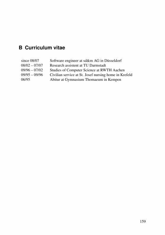
B Curriculum vitae
since 08/07 Software engineer at sd&m AG in Düsseldorf08/02 – 07/07 Research assistent at TU Darmstadt09/96 – 07/02 Studies of Computer Science at RWTH Aachen09/95 – 09/96 Civilian service at St. Josef nursing home in Krefeld06/95 Abitur at Gymnasium Thomaeum in Kempen
159

Bibliography
[ABS04] C. Amelunxen, L. Bichler, and A. Schürr. Codegenerierung für As-soziationen in MOF 2.0. In Proceedings Modellierung 2004, vol-ume P-45 of Lecture Notes in Informatics, pages 149–168, Bonn, 32004. Gesellschaft für Informatik.
[ADS02] F. Altheide, H. Dörr, and A. Schürr. Requirements to a Frameworkfor Sustainable Integration of System Development Tools. In Proc.3rd European Systems Engineering Conference, 2002.
[AKRS03] C. Amelunxen, A. Königs, T. Rötschke, and A. Schürr. AdaptingFUJABA for Building a Meta Modelling Framework. In H. Gieseand A. Zündorf, editors, Proc. FUJABA Days 2003, pages 29–33. University of Kassel, 2003. ftp://ftp.upb.de/doc/techreports/Informatik/tr-ri-04-247.pdf.
[Alt07] O. Alt. Deriving reusable system test cases from SysML models. InProc. Software and Systems Quality Conference, 2007.
[Ame08] C. Amelunxen. Metamodel-based Design Rule Checking and En-forcement. PhD thesis, Universität Darmstadt, 2008. to appear.
[BCM+94] A.W. Brown, D.J. Carney, E.J. Morris, D.B. Smith, and P.F. Zarella.Principles of CASE Tool Integration. Oxford University Press,1994.
[Bec08] S. Becker. Integratoren zur Konsistenzsicherung von Dokumentenin Entwicklungsprozessen. PhD thesis, RWTH Aachen, 2008. Ger-man.
[Bic04] L. Bichler. Codegeneratoren für MOF-basierte Model-lierungssprachen. PhD thesis, Universität der BundeswehrMünchen, 2004. German, http://www.es.tu-darmstadt.de/download/publications/bichler2004-dis.pdf.
[BNvBK06] D. Balasubramanian, A. Narayanan, C. van Buskirk, and G. Karsai.The Graph Rewriting and Transformation Language: GReAT. InProc. 3rd International Workshop on Graph Based Tools, 2006.
160

Bibliography
[CH03] K. Czarnecki and S. Helsen. Classification of Model Trans-formation Approaches. In online Proc. 2nd OOPSLA’03Workshop on Generative Techniques in the Context of MDA,2003. http://www.softmetaware.com/oopsla2003/czarnecki.pdf.
[dLV02] J. de Lara and H. Vangheluwe. AToM3: A Tool for Multi-formalismand Meta-modelling. In Proc. 5th International Conference onFundamental Approaches to Software Engineering, volume 2306 ofLecture Notes In Computer Science (LNCS), pages 174–188, 2002.
[FK03] R. Freude and A. Königs. Tool integration with consistency re-lations and their visualization. In H. Dörr and A. Schürr, edi-tors, Tool-Integration in System Development Satellite Workshop ofESEC/FSE 2003, Helsinki, Finland, pages 6–10, 2003.
[Gab02] J. Gable. Enterprise Application Integration. Information Manage-ment Jounal, 2002.
[GJSB05] J. Gosling, B. Joy, G. Steele, and G. Bracha. The Java(TM) Lan-guage Specification. Prentice Hall PTR, 2005.
[GK07] J. Greenyer and E. Kindler. Reconciling TGGs with QVT. In ModelDriven Engineering Languages and Systems, volume 4735/2007 ofLNCS, pages 16–30. Springer Verlag, 2007.
[Gra02] M. Grand. Patterns in Java: A Catalog of Reusable Design PatternsIllustrated with UML, volume 1. Wiley, 2nd edition, 2002.
[Hec06] R. Heckel. Graph Transformation in a Nutshell. In Proc. of theSchool of SegraVis Research Training Network on Foundations ofVisual Modelling Techniques (FoVMT 2004), volume 148 of Elec-tronic Notes in Theoretical Computer Science (ENTCS), pages 187–198, 2006.
[HM85] D. Heimbigner and D. McLeod. A Federated Architecture for Infor-mation Management. In ACM Transactions on Information Systems,volume 3, pages 253–278. ACM, 1985.
[JK05] F. Jouault and I. Kurtev. Transforming Models with ATL. In ModelTransformations in Practice Satellite Workshop of MODELS 2005,2005.
161

Bibliography
[JKS06] J. Jakob, A. Königs, and A. Schürr. Non-materialized Model ViewSpecification with Triple Graph Grammars. In A. Corradini, editor,Proc. International Conference on Graph Transformations, volume4178 of Lecture Notes in Computer Science (LNCS), pages 321–335. Springer Verlag, 2006.
[KAK+08] F. Klar, C. Amelunxen, A. Königs, T. Rötschke, and A. Schürr.Metamodel-based Tool Integration with MOFLON. In Proc. 30thInternational Conference on Software Engineering, 2008.
[KKG05] F. Klar, T. Kühne, and M. Girschick. SPin - A Fujaba Plugin forArchitecture Stratification. In Proc. 3rd International Fujaba Days,2005.
[KKS07] F. Klar, A. Königs, and A. Schürr. Model Transformation in theLarge. In Proc. 6th joint meeting of the European software engi-neering conference and the ACM SIGSOFT symposium on the foun-dations of software engineering,, ACM Digital Library Proceedings,pages 285–294. ACM Press, 2007.
[KR02] R. Kimbal and M. Ross. The Data Warehouse Toolkit: The Com-plete Guide to Dimensional Modeling. Wiley, 2nd edition, 2002.
[KS06] A. Königs and A. Schürr. MDI - a Rule-Based Multi-Document andTool Integration Approach. Special Section on Model-based ToolIntegration in Journal of Software&System Modeling, 5(4):349–368, 2006.
[OMG02] OMG. Request for Proposal: MOF 2.0 Query / Views / Transfor-mations RFP, 2002. http://www.omg.org/cgi-bin/doc?ad/2002-04-10.
[OMG03] OMG. MDA Guide Version 1.0.1, 2003. http://www.omg.org/cgi-bin/doc?omg/03-06-01.
[OMG05a] OMG. MOF 2.0/XMI Mapping Specification, v2.1, 2005. http://www.omg.org/cgi-bin/doc?formal/2005-09-01.
[OMG05b] OMG. MOF QVT Final Adopted Specification, 2005. http://www.omg.org/cgi-bin/doc?ptc/2005-11-01.
[OMG06a] OMG. Meta Object Facility (MOF) Core Specification Ver-sion 2.0, 2006. http://www.omg.org/cgi-bin/doc?formal/2006-01-01.
162

Bibliography
[OMG06b] OMG. Object Constraint Language Version 2.0, 2006. http://www.omg.org/cgi-bin/doc?formal/2006-05-01.
[OMG07] OMG. Unified Modeling Language: Infrastructure Version 2.1.1,2007. http://www.omg.org/cgi-bin/doc?formal/07-02-06.
[PR69] J. L. Pfalz and A. Rosenfeld. Web Grammars. In Proc. 1st Interna-tional Joint Conference on AI, 1969.
[Pra71] T.W. Pratt. Pair Grammars, Graph Languages and String-to-GraphTranslations. Journal of Computer and System Sciences, 5:560–595,1971. Academic Press.
[Röt04] T. Rötschke. Adding Pluggable Meta Models to FUJABA. In Proc.2nd International Fujaba Days, pages 57–61, 2004.
[Röt09] T. Rötschke. Meta Model-Based Evolution of Domain-Specific Soft-ware Architectures for Embedded Systems. PhD thesis, TU Darm-stadt, 2009. to appear.
[Sch91] A. Schürr. Operationales Spezifizieren mit programmierten Gra-phersetzungssystemen. PhD thesis, RWTH Aachen, 1991. German.
[Sch94] A. Schürr. Specification of Graph Translators with Triple GraphGrammars. In G. Tinhofer, editor, Proc. WG’94 20th Int. Workshopon Graph-Theoretic Concepts in Computer Science, volume 903 ofLecture Notes in Computer Science (LNCS), pages 151–163, Hei-delberg, 1994. Springer Verlag.
[Som06] I. Sommerville. Software Engineering. Addison Wesley, 8th edition,2006.
[Sun02] Sun Microsystems. JSR-000040 The Java™ Meta-data Interface (JMI) Specification Version 1.0, 2002.http://jcp.org/aboutJava/communityprocess/final/jsr040/index.html.
[TB94] G. Taentzer and M. Beyer. Amalgamated Graph Transformationsand Their Use for Specifying AGG - an Algebraic Graph GrammarSystem. In H.-J. Schneider and H. Ehrig, editors, Graph Trans-formations in Computer Science, volume 776 of Lecture Notes inComputer Science (LNCS), 1994.
163
Bibliography
[Wag01] R. Wagner. Realisierung eines diagrammübergreifenden Konsis-tenzmanagement-Systems für UML-Spezifikationen. Diploma the-sis, University of Paderborn, 2001. German.
[Wag08] R. Wagner. Inkrementelle Modellsynchronisation. PhD thesis, Uni-versität Paderborn, 2008. German.
[Zha94] J.L. Zhao. Schema Coordination in Federated Database Manage-ment: A Comparison with Schema Integration. In Proc. Workshopon Information Technology and Systems, 1994.
[Zün01] A. Zündorf. Rigorous Object Oriented Software Development. Uni-versity of Paderborn, 2001. Habilitation thesis.
164


![Newcastle University ePrintseprint.ncl.ac.uk/file_store/production/193154/12BEFF6C-5A9F-4CD9-AE… · Version of file: Author final This ... given by Rhodes [4]. ... formulas to encapsulate](https://static.fdocuments.in/doc/165x107/5aa0826a7f8b9a76178e17e9/newcastle-university-version-of-file-author-final-this-given-by-rhodes-4.jpg)


![GUITAR & BASS ACCESSORIES 01 - dl.owneriq.netdl.owneriq.net/b/b4bffbec-df8d-4cd9-8543-864c23c4009f.pdfGUITAR & BASS ACCESSORIES 01 31 TUNERS 01 01 02 02 02 02 01 01 ... [ Auto-tune]](https://static.fdocuments.in/doc/165x107/5ada02e07f8b9a6d7e8c21b4/guitar-bass-accessories-01-dl-bass-accessories-01-31-tuners-01-01-02-02-02-02.jpg)

