MODEL G8749 DRUM/FLAP SANDER - cdn2.grizzly.comcdn2.grizzly.com/manuals/g8749_m.pdf · your machine...
32
MODEL G8749 DRUM/FLAP SANDER OWNER'S MANUAL COPYRIGHT © 2000 BY GRIZZLY INDUSTRIAL, INC., REVISED SEPTEMBER, 2014 (ST) WARNING: NO PORTION OF THIS MANUAL MAY BE REPRODUCED IN ANY SHAPE OR FORM WITHOUT THE WRITTEN APPROVAL OF GRIZZLY INDUSTRIAL, INC. #DS3216 PRINTED IN CHINA
Transcript of MODEL G8749 DRUM/FLAP SANDER - cdn2.grizzly.comcdn2.grizzly.com/manuals/g8749_m.pdf · your machine...

MODEL G8749DRUM/FLAP SANDER
OWNER'S MANUAL
COPYRIGHT © 2000 BY GRIZZLY INDUSTRIAL, INC., REVISED SEPTEMBER, 2014 (ST)WARNING: NO PORTION OF THIS MANUAL MAY BE REPRODUCED IN ANY SHAPE
OR FORM WITHOUT THE WRITTEN APPROVAL OF GRIZZLY INDUSTRIAL, INC. #DS3216 PRINTED IN CHINA

This manual provides critical safety instructions on the proper setup, operation, maintenance, and service of this machine/tool. Save this document, refer to it often, and use it to instruct other operators.
Failure to read, understand and follow the instructions in this manual may result in fire or serious personal injury—including amputation, electrocution, or death.
The owner of this machine/tool is solely responsible for its safe use. This responsibility includes but is not limited to proper installation in a safe environment, personnel training and usage authorization, proper inspection and maintenance, manual availability and compre-hension, application of safety devices, cutting/sanding/grinding tool integrity, and the usage of personal protective equipment.
The manufacturer will not be held liable for injury or property damage from negligence, improper training, machine modifications or misuse.
Some dust created by power sanding, sawing, grinding, drilling, and other construction activities contains chemicals known to the State of California to cause cancer, birth defects or other reproductive harm. Some examples of these chemicals are:
• Lead from lead-based paints.• Crystalline silica from bricks, cement and other masonry products.• Arsenic and chromium from chemically-treated lumber.
Your risk from these exposures varies, depending on how often you do this type of work. To reduce your exposure to these chemicals: Work in a well ventilated area, and work with approved safety equip-ment, such as those dust masks that are specially designed to filter out microscopic particles.

INTRODUCTION ............................................................................................................................... 2Manual Accuracy ........................................................................................................................ 2Contact Info ................................................................................................................................ 2Functional Overview ................................................................................................................... 2Identification ............................................................................................................................... 3Machine Data Sheet ................................................................................................................... 4
SECTION 1: SAFETY ....................................................................................................................... 5Safety Instructions for Machinery ............................................................................................... 5Additional Safety Instructions Sanders ...................................................................................... 7
SECTION 2: CIRCUIT REQUIREMENTS ........................................................................................ 8110V Operation .......................................................................................................................... 8
SECTION 3: SETUP ......................................................................................................................... 9Setup Safety ............................................................................................................................... 9Items Needed for Setup ............................................................................................................. 9Unpacking .................................................................................................................................. 9Inventory ................................................................................................................................... 10Site Considerations .................................................................................................................. 10Test Run ................................................................................................................................... 11Mounting ................................................................................................................................... 12Assembly .................................................................................................................................. 12
SECTION 4: OPERATIONS ........................................................................................................... 15Operation Safety ...................................................................................................................... 15Sanding Tips ............................................................................................................................ 15ON/OFF Switch ........................................................................................................................ 16Drum Sanding .......................................................................................................................... 16Flap Sanding ............................................................................................................................ 16
SECTION 5: ACCESSORIES ......................................................................................................... 17
SECTION 6: MAINTENANCE......................................................................................................... 18Schedule .................................................................................................................................. 18Cleaning ................................................................................................................................... 18Lubrication ................................................................................................................................ 18Replacing Sanding Sleeves ..................................................................................................... 18Replacing Flap Sandpaper/Brushes ........................................................................................ 19
SECTION 7: SERVICE ................................................................................................................... 20Troubleshooting ........................................................................................................................ 20
SECTION 8: WIRING ...................................................................................................................... 22Wiring Safety Instructions ........................................................................................................ 22Wiring Diagram......................................................................................................................... 23
SECTION 9: PARTS ....................................................................................................................... 24Parts Breakdown ...................................................................................................................... 24Parts List .................................................................................................................................. 25
WARRANTY AND RETURNS ........................................................................................................ 29
Table of Contents

-2- G8749 Drum/Flap Sander
INTRODUCTION
We stand behind our machines. If you have any service questions, parts requests or general ques-tions about the machine, please call or write us at the location listed below.
Grizzly Industrial, Inc.1203 Lycoming Mall Circle
Muncy, PA 17756Phone: (570) 546-9663
Fax: (800) 438-5901E-Mail: [email protected]
If you have any comments regarding this manual, please write to us at the address below:
Grizzly Industrial, Inc.C/O Technical Documentation Manager
P.O. Box 2069Bellingham, WA 98227-2069Email: [email protected]
Contact Info
Functional OverviewManual Accuracy
We are proud to offer this manual with your new machine! We've made every effort to be exact with the instructions, specifications, drawings, and photographs of the machine we used when writ-ing this manual. However, sometimes errors do happen and we apologize for them.
Also, owing to our policy of continuous improve-ment, your machine may not exactly match the manual. If you find this to be the case, and the difference between the manual and machine leaves you in doubt, immediately call our techni-cal support for updates or clarification.
For your convenience, we always keep current Grizzly manuals and most updates available on our website at www.grizzly.com. Any updates to your machine will be reflected in these documents as soon as they are complete. Visit our site often to check for the latest updates!
The Model G8749 Drum/Flap Sander is generally used for edge contour sanding using the sand-ing drums, as shown in Figure 1, or for round or spherical sanding using the flap sander, as shown in Figure 2.
Figure 1. Typical drum sanding operation.
Figure 2. Typical flap sanding operation.

G8749 Drum/Flap Sander -3-
Identification
Figure 3. Model G8749 identification.
Mounting Holes
Motor
Sanding Drum
ON/OFF Switch
Flap Sander

-4- G8749 Drum/Flap Sander
The information contained herein is deemed accurate as of 9/1/2014 and represents our most recent product specifications.Due to our ongoing improvement efforts, this information may not accurately describe items previously purchased. PAGE 1 OF 1Model G8749
MACHINE DATASHEET
Customer Service #: (570) 546-9663 · To Order Call: (800) 523-4777 · Fax #: (800) 438-5901
MODEL G8749 DRUM / FLAP SANDERProduct Dimensions:
Weight................................................................................................................................................................ 57 lbs.Width (side-to-side) x Depth (front-to-back) x Height................................................................. 30 x 7-1/2 x 10-1/2 in.Footprint (Length x Width)......................................................................................................................... 9 x 6-1/2 in.
Shipping Dimensions:
Type..................................................................................................................................................... Cardboard BoxContent........................................................................................................................................................... MachineWeight................................................................................................................................................................ 69 lbs.Length x Width x Height....................................................................................................................... 15 x 31 x 10 in.
Electrical:
Power Requirement........................................................................................................... 110V, Single-Phase, 60 HzPrewired Voltage.................................................................................................................................................. 110VFull-Load Current Rating........................................................................................................................................ 10AMinimum Circuit Size.............................................................................................................................................. 15AConnection Type....................................................................................................................................... Cord & PlugPower Cord Included.............................................................................................................................................. YesPower Cord Length................................................................................................................................................. 5 ft.Power Cord Gauge......................................................................................................................................... 16 AWGPlug Included.......................................................................................................................................................... YesIncluded Plug Type................................................................................................................................................ 5-15Switch Type.................................................................................................. Paddle Safety Switch w/Removable Key
Motors:Main
Type................................................................................................................. TEFC Capacitor-Start InductionHorsepower................................................................................................................................................ 1 HPPhase............................................................................................................................................ Single-PhaseAmps............................................................................................................................................................ 10ASpeed................................................................................................................................................ 1725 RPMPower Transfer ............................................................................................................................... Direct DriveBearings..................................................................................................... Shielded & Permanently Lubricated
Other Specifications:
Country of Origin ................................................................................................................................................ ChinaWarranty ........................................................................................................................................................... 1 YearApproximate Assembly & Setup Time ........................................................................................................ 30 MinutesSerial Number Location .............................................................................................. ID Label on Front of Top CoverISO 9001 Factory .................................................................................................................................................... NoCSA, ETL, or UL Certified/Listed ............................................................................................................................ No
Features:
Flap Sander Supplied with 120 Grit PaperIncludes 3-1/4" and 4-3/4" Inflatable Sanding DrumsToggle On/Off Switch with Safety Lock
Machine Data Sheet

G8749 Drum/Flap Sander -5-
Safety Instructions for Machinery
For Your Own Safety, Read Instruction Manual Before Operating this Machine
The purpose of safety symbols is to attract your attention to possible hazardous conditions. This manual uses a series of symbols and signal words intended to convey the level of importance of the safety messages. The progression of symbols is described below. Remember that safety messages by themselves do not eliminate danger and are not a substitute for proper accident prevention measures.
Indicates a potentially hazardous situation which, if not avoided, MAY result in minor or moderate injury. It may also be used to alert against unsafe practices.
Indicates a potentially hazardous situation which, if not avoided, COULD result in death or serious injury.
Indicates an imminently hazardous situation which, if not avoided, WILL result in death or serious injury.
This symbol is used to alert the user to useful information about proper operation of the machine.NOTICE
WEARING PROPER APPAREL. Do not wear clothing, apparel, or jewelry that can become entangled in moving parts. Always tie back or cover long hair. Wear non-slip footwear to avoid accidental slips which could cause a loss of workpiece control.
HEARING PROTECTION. Always wear hear-ing protection when operating or observiing loud machinery. Extended exposure to this noise without hearing protection can cause permanent hearing loss.
MENTAL ALERTNESS. Be mentally alert when running machinery. Never operate under the influence of drugs or alcohol, when tired, or when distracted.
OWNER’S MANUAL. Read and understand this owner’s manual BEFORE using machine. Untrained users can be seriously hurt.
EYE PROTECTION. Always wear ANSI-approved safety glasses or a face shield when operating or observing machinery. to reduce the risk of eye injury or blindness from fly-ing particles Everyday eyeglasses are not approved safety glasses.
HAzARDOUS DUST. Dust created while using machinery may cause cancer, birth defects, or long-term respiratory damage. Be aware of dust hazards associated with each workpiece material, and always wear a NIOSH-approved respirator to reduce your risk.
Safety Instructions for Machinery
SECTION 1: SAFETY

-6- G8749 Drum/Flap Sander
DISCONNECTING POWER SUPPLY. Always disconnect machine from power supply before servicing, adjusting, or changing cutting tools (bits, blades, cutters, etc.). Make sure switch is in OFF position before reconnecting to avoid an unexpected or unintentional start.
INTENDED USE. Only use the machine for its intended purpose and only use recommended accessories. Never stand on machine, modify it for an alternative use, or outfit it with non-approved accessories.
STABLE MACHINE. Unexpected movement during operations greatly increases the risk of injury and loss of control. Verify machines are stable/secure and mobile bases (if used) are locked before starting.
FORCING MACHINERY. Do not force machine. It will do the job safer and better at the rate for which it was designed.
GUARDS & COVERS. Guards and covers can protect you from accidental contact with mov-ing parts or flying debris. Make sure they are properly installed, undamaged, and working correctly before using machine.
REMOVING TOOLS. Never leave adjustment tools, chuck keys, wrenches, etc. in or on machine—especially near moving parts. Verify removal before starting!
AWKWARD POSITIONS. Keep proper foot-ing and balance at all times when operating machine. Do not overreach! Avoid awkward hand positions that make workpiece control dif-ficult or increase the risk of accidental injury.
DANGEROUS ENVIRONMENTS. Do not use machinery in wet locations, cluttered areas, around flammables, or in poorly-lit areas. Keep work area clean, dry, and well lighted to mini-mize risk of injury.
Safety Instructions for MachineryAPPROVED OPERATION. Untrained operators can be seriously hurt by machinery. Only allow trained or properly supervised people to use machine. When machine is not being used, dis-connect power, remove switch keys, or lock-out machine to prevent unauthorized use—especially around children. Make workshop kid proof!
CHILDREN & BYSTANDERS. Keep children and bystanders a safe distance away from work area. Stop using machine if children or bystand-ers become a distraction.
FEED DIRECTION. Unless otherwise noted, feed work against the rotation of blades or cutters. Feeding in the same direction of rotation may pull your hand into the cut.
SECURING WORKPIECE. When required, use clamps or vises to secure workpiece. A secured workpiece protects hands and frees both of them to operate the machine.
UNATTENDED OPERATION. Never leave machine running while unattended. Turn machine Off and ensure all moving parts completely stop before walking away.
MAINTENANCE & INSPECTION. A machine that is not properly maintained may operate unpre-dictably. Follow all maintenance instructions and lubrication schedules to keep machine in good working condition. Regularly inspect machine for loose bolts, alignment of critical parts, binding, or any other conditions that may affect safe opera-tion. Always repair or replace damaged or mis-adjusted parts before operating machine.
EXPERIENCING DIFFICULTIES. If at any time you are experiencing difficulties performing the intended operation, stop using the machine! Contact our Technical Support Department at (570) 546-9663.

G8749 Drum/Flap Sander -7-
Additional Safety Instructions Sanders1. FEEDING WORKPIECE. To avoid the risk
of your hands being pulled into the machine, do not jam workpiece into the sanding attachment during operation. Firmly grasp the workpiece in both hands and ease it into the machine using light pressure.
2. ENTANGLEMENT HAZARD. To avoid entanglement injuries, do not wear loose clothing, jewelry, or gloves when using this machine. Roll up long sleeves and tie back long hair.
3. HAND PROTECTION. Do not place your hands near or in contact with the sand-ing attachments during operation. Never put your hands or fingers between the workpiece and the sander during opera-tion.
4. INSPECTING WORKPIECES. Always inspect the workpiece for nails, staples, knots, and other imperfections that could be dislodged and thrown from the machine during operation, which could cause seri-ous personal injury.
5. PROTECTIVE EQUIPMENT. Dust and chips become airborne at a high rate of speed during operation, becoming haz-ards to eyes and lungs. Always wear ANSI approved safety glasses or a face shield and a respirator when using this sander.
No list of safety guidelines can be complete. Every shop environment is different. Always consider safety first, as it applies to your individual working conditions. Use this and other machinery with caution and respect. Failure to do so could result in serious per-sonal injury, damage to equipment, or poor work results.
Like all machinery there is potential danger when operating this machine. Accidents are frequently caused by lack of familiarity or failure to pay attention. Use this machine with respect and caution to decrease the risk of operator injury. If normal safety pre-cautions are overlooked or ignored, serious personal injury may occur.
6. ROTATION DIRECTION. To avoid entan-glement injuries, always be aware of the rotation direction of the sanding attach-ments.
7. UNATTENDED OPERATION. To avoid the risk of unauthorized use or accidental con-tact with the sanding attachments, never leave the machine running unattended. Turn the machine OFF after every use and remove the switch disabling key.
8. ADJUSTMENT, MAINTENANCE, AND SERVICE. Perform machine inspections and maintenance service promptly and when needed. Always disconnect the machine from power when performing adjustments, maintenance, or service to avoid injuries from accidental start-up or electrocution.
9. SANDING ATTACHMENTS. Always make sure the sanding attachments are correctly mounted and secure before turning the machine on. Keep these components in good working order.
10. EXPERIENCING DIFFICULTIES. If at any time you are experiencing difficulties per-forming the intended operation, stop using the machine and contact Tech Support at (570) 546-9663.

-8- G8749 Drum/Flap Sander
Figure 4. Typical 5-15 plug and receptacle.
Grounding Prong
Neutral Hot
5-15 PLUG
GROUNDED5-15 RECEPTACLE
110V Operation
Full Load Amperage DrawThis machine draws the following amps under maximum load:
Amp Draw .............................................. 10 Amps
Power Supply Circuit RequirementsYou MUST connect your machine to a grounded circuit that is rated for the amperage given below. Never replace a circuit breaker on an existing cir-cuit with one of higher amperage without consult-ing a qualified electrician to ensure compliance with wiring codes. If you are unsure about the wiring codes in your area or you plan to con-nect your machine to a shared circuit, consult a qualified electrician.
Minimum Circuit Size ............................. 15 Amps
This machine MUST have a ground prong in the plug to help ensure that it is grounded. DO NOT remove ground prong from plug to fit into a two-pronged outlet! If the plug will not fit the outlet, have the proper outlet installed by a qualified electrician.
Extension CordsWe do not recommend using extension cords, but if you find it absolutely necessary:
• Use at least a 14 gauge cord that does not exceed 50 feet in length!
• The extension cord must have a ground wire and plug pin.
• A qualified electrician MUST size cords over 50 feet long to prevent motor damage.
SECTION 2: CIRCUIT REQUIREMENTS
Serious personal injury could occur if you connect the machine to power before com-pleting the setup process. DO NOT connect the machine to the power until instructed later in this manual.
Electrocution or fire could result if machine is not grounded and installed in compliance with electrical codes. Compliance MUST be verified by a qualified electrician!
Power Connection DeviceThe Model G8749 comes with a 5-15 plug, similar to Figure 4, to connect the machine to power.
G8749 Drum/Flap Sander -9-
Wear safety glasses dur-ing the entire setup pro-cess!
This machine presents serious injury hazards to untrained users. Read through this entire manu-al to become familiar with the controls and opera-tions before starting the machine!
Setup Safety
SECTION 3: SETUP
The following items are needed to complete the setup process, but are not included with your machine:
Description Qty• Wrenches 14, 19mm ..........................1 Each• Mounting Hardware (Page 11) ... As Needed
Items Needed for Setup
Your machine was carefully packaged for safe transportation. Remove the packaging materials from around your machine and inspect it. If you discover the machine is damaged, please imme-diately call Customer Service at (570) 546-9663 for advice.
Save the containers and all packing materials for possible inspection by the carrier or its agent. Otherwise, filing a freight claim can be difficult.
When you are completely satisfied with the condi-tion of your shipment, inventory the contents.
Unpacking

-10- G8749 Drum/Flap Sander
Inventory
The following is a description of the main compo-nents shipped with your machine. Lay the compo-nents out to inventory them.
Note: If you can't find an item on this list, check the mounting location on the machine or examine the packaging materials carefully. Occasionally we pre-install certain components for shipping purposes.
Component Inventory: (Figure 5) QtyA. Sanding Drum 3 1⁄4" x 8" .............................. 1B. Flap Sander ................................................ 1C. Sanding Drum 4 3⁄4" x 8".............................. 1D. Arbor Bolt & Flat Washer (LH) ..........1 EachE. Arbor Bolt & Flat Washer (RH) ..........1 EachF. Flap Sander Arbor Bolt & Flange ......1 EachG. End Caps .................................................... 2
If any nonproprietary parts are missing (e.g. a nut or a washer), we will gladly replace them; or for the sake of expediency, replacements can be obtained at your local hardware store.
SUFFOCATION HAZARD!Immediately discard all plas-tic bags and packing materi-als to eliminate choking/suf-focation hazards for children and animals.
Workbench LoadRefer to the Machine Data Sheet for the weight and footprint specifications of your machine. Some workbenches may require additional rein-forcement to safely support the machine.
Placement LocationConsider existing and anticipated needs, size of material to be processed through each machine, and space for auxiliary stands, work tables or other machinery when establishing a location for your new machine. See Figure 6 for the minimum working clearances.
Children and visitors may be seriously injured if unsuper-vised around this machine. Lock entrances to the shop or disable start switch or power connection to prevent unsupervised use.
Site Considerations
Figure 6. Minimum working clearances.
30"
9"
Figure 5. Model G8749 inventory.
AB
C
DEFG

G8749 Drum/Flap Sander -11-
Mounting
Due to the significant forces exerted on the sander during operation, you must mount it to a workbench. We recommend that you use one of the following methods to secure your sander to the workbench before using it.
The strongest mounting option is a "Through Mount" where holes are drilled all the way through the workbench, and hex bolts, washers, and hex nuts are used to secure the sander to the workbench.
Machine Base
Workbench
Lag Screw
Flat Washer
Figure 8. Example of a direct mount setup.
Another option for mounting is a "Direct Mount" where the machine is simply secured to the work-bench with a lag screw.
Machine Base
Workbench
HexBolt
Flat Washer
Flat Washer Lock Washer
Hex Nut
Figure 7. Example of a through mount setup.
Test Run
Once the assembly is complete, test run your machine to make sure it runs properly and is ready for regular operation.
The test run consists of verifying the following: 1) The motor powers up and runs correctly, and 2) the safety disabling mechanism works correctly.
If, during the test run, you cannot easily locate the source of an unusual noise or vibration, stop using the machine immediately, then review Troubleshooting on Page 20.
If you still cannot remedy a problem, contact our Tech Support at (570) 546-9663 for assistance.
To test run the machine:
1. Make sure you have read the safety instruc-tions at the beginning of the manual and that the machine is set up properly.
2. Make sure all tools and objects used during setup are cleared away from the machine.
3. Connect the machine to the power source.
4. Verify that the machine is operating correctly by turning the it ON.
—When operating correctly, the machine runs smoothly with little or no vibration or rubbing noises.
— Investigate and correct strange or unusual noises or vibrations before operating the machine further. Always disconnect the machine from power when investigating or correcting potential problems.

-12- G8749 Drum/Flap Sander
5. Turn the machine OFF.
6. Remove the switch disabling key, as shown in Figure 9.
7. Try to start the machine by flipping the paddle switch up to the ON position.
—If the machine does not start, the switch disabling feature is working as designed.
—If the machine starts, immediately stop it. The switch disabling feature is not working correctly. This safety feature must work properly before proceeding with regular operations. Call Tech Support for help.
Figure 9. Removing switch key from paddle switch.
Assembly
The flap sander is designed to be mounted only on the left side of the machine, whereas the drum sanders can be mounted on either side.
Attaching Flap Sander1. DISCONNECT SANDER FROM POWER!
2. When removed from the shipping box, the flap sander is held together by two tie wraps. Hold the assembly together from top to bot-tom, then remove the ties and store them for future use.
Note: If the brushes should come loose from the end plates during this step, refer to Replacing Flap Sandpaper/Brushes on Page 19 for detailed instructions on how to put the assembly back together.
3. Position the flap sander so the sanding sur-face of the paper is facing you, then carefully slide it onto the left hand arbor, as shown in Figure 10.
Figure 10. Installing flap sander.
4. Secure the flap sander by threading the flap sander arbor bolt and flange into the spindle, as shown in Figure 10. Make sure to fully tighten the bolt.
Note: This arbor bolt has left-hand threads and tightens by rotating it counterclockwise.

G8749 Drum/Flap Sander -13-
Reversing Sleeve RotationThe sanding drums are shipped with 120 grit sanding sleeves already installed. The sleeve rotations are configured so that the large diameter drum is mounted on the right side of the sander and the smaller drum is mounted on the left.
If you want to change the mounting location of the drums from the positions above, you must remove the sanding sleeve and turn it around so that the sleeve rotation matches the spindle rotation.
To reverse the sleeve rotation:
1. DISCONNECT SANDER FROM POWER!
2. Remove the protective cap on the air valve, then push the valve stem to release all of the air pressure from the drum (see Figure 11).
3. Remove the sleeve from the drum, turn it around, then slide it back onto the drum.
4. Hold the mounted sleeve up to the spindle that you will be installing them on, then make sure the sleeve rotation arrows and the rota-tion arrow on the spindle housing match.
Always check the sanding drum air pressure before using it. Only use a hand-operated air pump to inflate the sanding drum to 10 PSI. If the drum is over-inflated, the drum may burst with considerable force, which could cause serious personal injury.
Mounting Sanding DrumIt is important that the air pressure of the sanding drum be maintained at 10 PSI to safely hold the sanding sleeve in place.
To check air pressure and mount the sanding drum:
1. DISCONNECT SANDER FROM POWER!
2. Remove the air valve protective cap, then use a quality air pressure gauge to check the drum air pressure, as shown in Figure 12.
— If the drum air pressure is more than 10 PSI, push the valve stem in to reduce the air pressure. Use the gauge to recheck the pressure.
— If the drum air pressure is less than 10 PSI, use a hand-operated air pump to inflate the sanding drum to 10 PSI.
Figure 12. Checking sanding drum air pressure.
Figure 11. Matching the sleeve rotation with the spindle rotation.
Air Valve
Spindle Rotation Arrow
Sleeve Rotation Arrow

-14- G8749 Drum/Flap Sander
3. Replace the valve protective cap.
4. Slide the drum onto the spindle with the air valve facing out, then secure it by threading the arbor bolt with a flat washer through the drum and into the spindle, as shown in Figure 13. Make sure to fully tighten the bolt.
Note: The left spindle uses the arbor bolt with left-hand threads, which tightens by rotating it counterclockwise. The right spindle arbor bolt has right-hand threads and tightens by rotat-ing it clockwise.
Figure 13. Installing the sanding drum.
End Cap
Arbor Bolt & Flat Washer
5. Fully thread the end cap onto the arbor bolt to protect the valve stem during operation.
Note: One end cap also has left-hand threads and is mounted on the left side of the machine. The other cap has right-hand threads for the right side of the machine.

G8749 Drum/Flap Sander -15-
SECTION 4: OPERATIONS
Damage to your eyes and lungs could result from using this machine without proper pro-tective gear. Always wear safety glasses and a respirator when operating this machine.
NOTICEIf you have never used this type of machine or equipment before, WE STRONGLY REC-OMMEND that you read books, trade maga-zines, or get formal training before begin-ning any projects. Regardless of the con-tent in this section, Grizzly Industrial will not be held liable for accidents caused by lack of training.
Operation Safety
Loose hair, clothing, or jewelry could get caught in machinery and cause serious personal injury. Keep these items away from moving parts at all times to reduce this risk.
To reduce the risk of serious injury when using this machine, read and understand this entire manual before beginning any operations.
Sanding Tips
Your sander is a safe tool when used properly. In addition to the safety instructions in this manual, the most important safety consideration is to use common sense at all times.
Follow these rules when sanding:
• Make sure the sanding attachments are prop-erly installed and the spindle rotation of the sandpaper and spindle match.
• Use both hands and engage the workpiece with the spinning drum or flap sander slowly and firmly. There can be considerable force generated by the rotating device, causing the workpiece to fly out of your hands.
• Check the sanding drum air pressure before each use. Maintain the air pressure at 10 PSI. Do not over-inflate the drums.
• Always turn the sander ON and allow it to reach full speed before engaging the workpiece with the sandpaper.
• Use the correct sandpaper and grit for the job to ensure good sanding results.
• Do not use the sander as a replacement for a bandsaw or a planer. It is designed for finish work, not rough dimensioning.
• Keep your workpiece moving across the face of the drum or flap sander to prevent grooves or ruts in the workpiece surface.

-16- G8749 Drum/Flap Sander
ON/OFF Switch
This machine has a special safety ON/OFF pad-dle switch with a removable switch disabling key, as shown in Figure 14.
Turn the machine OFF, then remove the disabling key when leaving the machine to prevent acciden-tal or unauthorized start-up.
If the key is removed while the machine is run-ning, the sander can still be turned OFF. However, you need to re-install the key before turning the sander back ON.
Drum Sanding
Drum sanding is perfect for performing sanding operations on edge contours.
Use a soft sanding sleeve when sanding contours with rounded or soft edges. A hard sleeve is desir-able when the sanded edge is to be sharp.
Make sure the sanding sleeve is mounted on the drum and sander so that the sleeve rotation and spindle rotation match. The spindle will always rotate toward the operator.
Figure 15. Typical drum sanding operation.
Spindle & Drum Rotation Direction
Flap Sanding
Figure 15 shows a typical drum sanding opera-tion.
Flap sanding is useful for sanding rounded or spherical shapes. With the flap sander mounted on the left hand spindle, the abrasive side of the sanding flaps will rotate toward the operator. It is generally best to introduce the workpiece to the bottom of the flap sander, as shown in Figure 16, for the best control of the sanding forces.
Figure 16. Typical flap sanding operation.
Spindle & Flap Sander Rotation Direction
Figure 14. Removing the ON/OFF switch disabling key.
Switch Disabling
Key

G8749 Drum/Flap Sander -17-
SECTION 5: ACCESSORIESACCESSORIES
G9956—Remote Controlled Heavy-Duty Hanging Air FilterSet the duration and speed with the remote con-trol from as far away as 45 feet, then hold on as the fan spools up to draw a massive 1400 CFM through the 1 micron filter. Changes the air in a 20' x 20' x 8' room 26 times an hour. Hangs eas-ily from the ceiling. A three pocket internal filter bag simplifies cleaning. Motor is 1⁄3 HP, 110V, 3 amp. Dimensions: 30 1⁄8"L x 19 7⁄8"W x 16 3⁄8"H and weighs 74 lbs.
Figure 17. Model G9956 Hanging Air Filter.
Figure 18. Half-mask respirator with disposable cartridge filters.
T20514—Small Half-Mask RespiratorT20515—Medium Half-Mask RespiratorT20516—Large Half-Mask RespiratorWood and other types of dust can cause severe respiratory damage. If you work around dust every-day, a half-mask respirator can greatly reduce your risk. Compatible with safety glasses!
Aluminum Oxide Sanding SleevesG9196—3 1⁄4" Diameter, 60 GritG9197—3 1⁄4" Diameter, 80 GritG9198—3 1⁄4" Diameter, 100 GritG9199—3 1⁄4" Diameter, 120 GritG9200—3 1⁄4" Diameter, 150 GritG9201—3 1⁄4" Diameter, 180 GritG9208—4 3⁄4" Diameter, 60 GritG9209—4 3⁄4" Diameter, 80 GritG9210—4 3⁄4" Diameter, 100 GritG9211—4 3⁄4" Diameter, 120 GritG9212—4 3⁄4" Diameter, 150 GritG9213—4 3⁄4" Diameter, 180 Grit
6" x 60" J Weight Aluminum Oxide Rolls for Flap SanderG9187—120 GritG9188—180 GritG9189—220 Grit
H2491—Replacement Flap Brushes, Set of 12
T20501—Face Shield Crown Protector 4"T20502—Face Shield Crown Protector 7"T20503—Face Shield WindowT20448—Economy Clear Safety GlassesT20452—"Kirova" Anti-Reflective GlassesT20456—"Dakura" Clear Safety GlassesH0736—Shop Fox® Safety GlassesThese glasses meet ANSI Z87.1-2003 specifica-tions. Buy extras for visitors or employees. You can't be too careful with shop safety!
Figure 19. Our most popular eye protection.
T20448
H0736
T20452T20502
T20503
T20456
-18- G8749 Drum/Flap Sander
SECTION 6: MAINTENANCE
Always disconnect power to the machine before performing maintenance. Failure to do this may result in serious person-al injury.
For optimum performance from your machine, follow this maintenance schedule and refer to any specific instructions given in this section.
Daily Check:• Loose mounting bolts.• Damaged or worn sandpaper/brushes.• Sanding drum air pressure.• Worn or damaged wires.• Any other unsafe condition.
Daily Maintenance:• Clean machine.
Schedule
Cleaning the Model G8749 is relatively easy. Vacuum excess wood chips and sawdust, and wipe off the remaining dust with a dry cloth. If any resin has built up, use a resin dissolving cleaner to remove it.
Cleaning
Lubrication
Bearings are sealed and permanently lubricated, so simply leave them alone unless they need replacement.
Replacing Sanding Sleeves
Your sander is supplied with a large 4 3⁄4" x 8" sanding drum and a smaller 3 1⁄4" x 8" drum. Both drums will accept soft or hard sanding sleeves.
To replace the sanding sleeve:
1. DISCONNECT SANDER FROM POWER!
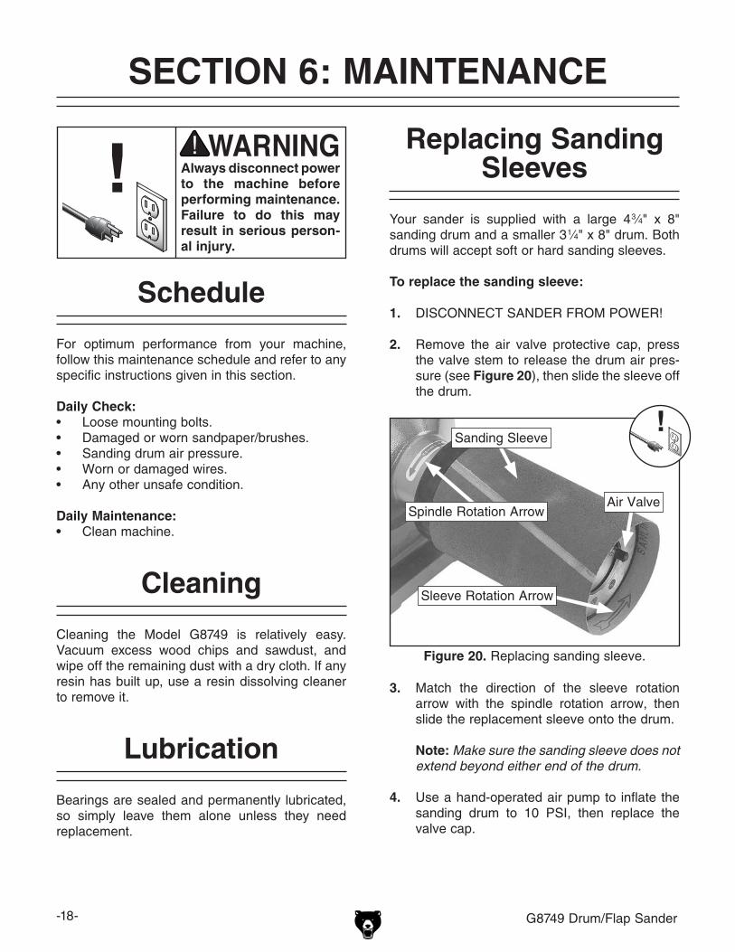
2. Remove the air valve protective cap, press the valve stem to release the drum air pres-sure (see Figure 20), then slide the sleeve off the drum.
Figure 20. Replacing sanding sleeve.
Air ValveSpindle Rotation Arrow
Sleeve Rotation Arrow
3. Match the direction of the sleeve rotation arrow with the spindle rotation arrow, then slide the replacement sleeve onto the drum.
Note: Make sure the sanding sleeve does not extend beyond either end of the drum.
4. Use a hand-operated air pump to inflate the sanding drum to 10 PSI, then replace the valve cap.
Sanding Sleeve

G8749 Drum/Flap Sander -19-
Replacing Flap Sandpaper/Brushes
To replace the flap sandpaper or brushes:
1. DISCONNECT SANDER FROM POWER!
2. While holding the outside end plate of the flap sander, remove the arbor bolt and flange, then remove the flap sander and place it upright on a flat surface.
3. Remove the top end plate, then remove one or two brushes to gain access to the retaining bars that secure the sandpaper.
Note: All of the replacement sandpaper needs to be oriented and installed so that the abrasive side faces the same direction and will face forward and down when the flap sander is properly mounted on the machine.
4. Each retaining bar holds two 4 1⁄2" x 6" pieces of sandpaper. Loosen the two screws secur-ing the retaining bar, then pull the old sand-paper pieces away.
5. Cut two new pieces of sandpaper from the selected grit, then slip them under the retain-ing bar so that the abrasive side faces away from the center of the flap sander, as shown in Figure 21.
6. Make sure the sandpaper pieces are even with one another and are centered in the retaining bar, then re-tighten the retaining bar screws to hold them in place.
7. If a flap brush is worn out or damaged, replace it with a new one. Insert each brush into the lower end plate and between two sandpaper pieces attached to the same retaining bar, as shown in Figure 22.
Figure 21. Replacing flap sandpaper.
Retaining Bar
8. After replacing the sandpaper and positioning the brushes, place the top end plate onto the flap sander.
9. As you lightly push down on the top plate, correctly position one brush to align with the recessed slot in the top plate, then rotate the flap sander and work on the one next to it. Continue this process until all of the brushes are correctly aligned and fully seated into the top plate.
Note: When storing the flap sander in a dry, protected place, secure the bottom and top end plates with tie wraps or string so that the end plates do not come loose and allow the brushes to fall out.
Figure 22. Sandpaper and brushes properly configured on the flap sander.

-20- G8749 Drum/Flap Sander
Review the troubleshooting and procedures in this section to fix or adjust your machine if a problem devel-ops. If you need replacement parts or you are unsure of your repair skills, then feel free to call our Technical Support at (570) 546-9663.
SECTION 7: SERVICE
Troubleshooting
Motor & Electrical
Symptom Possible Cause Possible SolutionMachine does not start or a breaker trips.
1. Switch disabling key removed.2. Power supply switched OFF or at fault.3. Plug/receptacle at fault/wired wrong.4. Start capacitor at fault.5. Motor connection wired wrong.6. Wall circuit breaker tripped.7. Wiring open/has high resistance.8. Motor ON/OFF switch at fault.9. Motor at fault.
1. Install switch disabling key.2. Ensure power supply is ON/has correct voltage.3. Test for good contacts; correct the wiring.4. Test/replace if faulty.5. Correct motor wiring connections (Page 23).6. Ensure circuit size is correct/replace weak breaker.7. Check/fix broken, disconnected, or corroded wires. 8. Replace switch.9. Test/repair/replace.
Machine stalls or is underpowered.
1. Workpiece material not suitable for machine.
2. Motor wired incorrectly.3. Plug/receptacle at fault.4. Motor bearings at fault.5. Machine undersized for task.
6. Motor overheated.7. Motor at fault.
1. Only cut wood; ensure moisture is below 20%.
2. Wire motor correctly (Page 23).3. Test for good contacts/correct wiring.4. Test/repair/replace.5. Clean/replace sandpaper; reduce feed rate/sanding
depth.6. Clean motor, let cool, and reduce workload.7. Test/repair/replace.
Machine has vibration or noisy operation.
1. Motor or component loose.
2. Incorrectly mounted to workbench.3. Motor mount bolts loose/broken.4. Motor bearings at fault.
1. Inspect/replace damaged bolts/nuts, and re-tighten with thread locking fluid.
2. Shim/tighten mounting hardware.3. Tighten/replace.4. Test by rotating shaft; rotational grinding/loose shaft
requires bearing replacement.

G8749 Drum/Flap Sander -21-
Operation
Symptom Possible Cause Possible SolutionDeep sanding groove or scars in workpiece.
1. Sandpaper grit too coarse.2. Workpiece sanded across grain.3. Workpiece pressure against sanding
abrasive too great.4. Workpiece held too still against sanding
abrasive.
1. Use finer grit sandpaper.2. Sand with the grain.3. Reduce pressure applied to the workpiece against
the sanding abrasive.4. Continuously move workpiece back-and-forth across
the sanding abrasive surface.
Abrasive grain rubs off the sandpaper.
1. Sandpaper has been stored in an incorrect environment.
2. Sandpaper has been folded or smashed.
1. Store sandpaper products away from extremely cold or hot temperatures and in a dry, protected location.
2. Store sanding sleeves or rolls so they are not smashed or bent; store sandpaper sheets flat.
Sanding surfaces clog quickly or burn.
1. Workpiece pressure against sanding abrasive too great.
2. Sanding softwood or stock with high residue.
1. Reduce pressure applied to the workpiece against the sanding abrasive.
2. Use different stock or accept the characteristics of the stock and plan on cleaning/replacing sandpaper frequently.
Burn marks on workpiece.
1. Sandpaper grit too fine.2. Workpiece pressure against sanding
abrasive too great.3. Workpiece held too still against sanding
abrasive.
1. Use coarser grit sandpaper.2. Reduce pressure applied to the workpiece against
the sanding abrasive.3. Continuously move workpiece back-and-forth across
the sanding abrasive surface.
Glazed surface on workpiece.
1. Sanding wet stock.
2. Sanding stock with high residue.
1. Properly dry stock before sanding so moisture content is less than 20%.
2. Use different stock or accept the characteristics of the stock and plan on cleaning/replacing sandpaper frequently.
W o r k p i e c e frequently pulled out of your hands.
1. Workpiece not correctly supported.
2. Engaging workpiece with the sander on a leading corner.
3. Starting sander with workpiece against sandpaper.
1. Hold workpiece firmly with both hands and engage with sander slowly; use additional holding/supporting devices for larger workpieces.
2. Start sanding workpiece on a trailing corner.
3. Start sander before engaging it with the workpiece.

-22- G8749 Drum/Flap Sander
These pages are current at the time of printing. However, in the spirit of improvement, we may make chang-es to the electrical systems of future machines. Study this section carefully. If there are differences between your machine and what is shown in this section, call Technical Support at (570) 546-9663 for assistance BEFORE making any changes to the wiring on your machine.
SECTION 8: WIRING
Wiring Safety Instructions1. SHOCK HAZARD. Working on wiring that
is connected to a power source is extremely dangerous. Touching electrified parts will result in personal injury including but not lim-ited to severe burns, electrocution, or death. Disconnect the power from the machine before servicing electrical components!
2. QUALIFIED ELECTRICIAN. Due to the inherent hazards of electricity, only a quali-fied electrician should perform wiring tasks on this machine. If you are not a quali-fied electrician, get help from one before attempting any kind of wiring job.
3. WIRE CONNECTIONS. All connections must be tight to prevent wires from loosen-ing during machine operation. Double-check all wires disconnected or connected during any wiring task to ensure tight connections.
4. MOTOR WIRING. The motor wiring shown in these diagrams is current at the time of printing, but it may not match your machine. Always use the wiring diagram inside the motor junction box.
5. MODIFICATIONS. Using aftermarket parts or modifying the wiring beyond what is shown in the diagram may lead to unpredictable results, including serious injury or fire.
6. WIRE/COMPONENT DAMAGE. Damaged wires or components increase the risk of seri-ous personal injury, fire, or machine damage. If you notice that any wires or components are damaged while performing a wiring task, replace those wires or components before completing the task.
7. CAPACITORS. Some capacitors store an electrical charge for up to five minutes after being disconnected from the power source. To avoid being shocked, wait at least this long before working on capacitors.
8. CIRCUIT REQUIREMENTS. You MUST fol-low the requirements on Page 8 when con-necting your machine to a power source.
9. EXPERIENCING DIFFICULTIES. If you are experiencing difficulties understanding the information included in this section, contact our Technical Support at (570) 546-9663.
The photos and diagrams included in this section are best viewed in color. You can view these pages in color at www.grizzly.com.

G8749 Drum/Flap Sander -23-READ ELECTRICAL SAFETY ON PAGE 22!
Sta
rt C
apac
itor
400M
FD
125
VA
C
Ground
Motor
ON/OFFSwitch
110VACNEMA 5-15 Plug
(As Recommended)
WARNING!SHOCK HAZARD!Disconnect powerbefore working onwiring.
Neutral
Ground
Hot
Wiring Diagram
Figure 23. Model G8749 wiring.
wiring diagram

-24- G8749 Drum/Flap Sander
1
7
8
9
10
10-1
11
12
13
17
18
19
19-1
20
21
22
23
24
25
2626-1
27
28
2930
31
32
34
35
35-1
36
3738
39
40
7
2A
Parts Breakdown
SECTION 9: PARTS

G8749 Drum/Flap Sander -25-
Parts ListREF PART # DESCRIPTION REF PART # DESCRIPTION1 P8749001 MOTOR 1HP 110V 60HZ 24 P8749024 LOCK BOLT M12-1.75 X 135 LH2A P8749002A COMPLETE FLAP SANDER ASSY 25 P8749025 FLANGE WASHER 30MM7 PW06M FLAT WASHER 12MM 26 P8749026 FLAP SANDER END CAP8 P8749008 ARBOR BOLT RH M12-1.75 X 22 26-1 P8749026-1 FLAP SANDER SHAFT9 P8749009 END CAP RH 27 P8749027 BRUSH10 P8749010 SANDING DRUM ASSY 4-3/4 X 8 28 P8749028 SANDPAPER 4-1/2 X 6 120 GRIT10-1 P8749010-1 DRUM BLADDER 4-3/4 X 8 29 P8749029 STRAIN RELIEF11 G9211 SANDING SLEEVE 4-3/4 X 8 120G 30 PWRCRD100L POWER CORD 110V W/5-15 PLUG12 P8749012 AIR VALVE 31 P8749031 BASE13 P8749013 VALVE CAP 32 P8749032 S CAPACITOR 400M 125V 3 X 1-3/817 P8749017 ARBOR BOLT LH M12-1.75 X 22 34 P8749034 MACHINE ID LABEL18 P8749018 END CAP LH 35 PS07M PHLP HD SCR M4-.7 X 819 P8749019 SANDING DRUM ASSY 3-1/4 X 8 35-1 PW05M FLAT WASHER 4MM19-1 P8749019-1 DRUM BLADDER 3-1/2 X 8 36 P8749036 CAPACITOR BRACKET20 G9199 SANDING SLEEVE 3-1/4 X 8 37 P8749037 COVER PLATE21 P8749021 SWITCH MOUNTING PLATE 38 PS07M PHLP HD SCR M4-.7 X 822 PSW06 PADDLE SWITCH 110V WITH KEY 39 PW01M FLAT WASHER 8MM23 PS38M PHLP HD SCR M4-.7 X 10 40 PB26M HEX BOLT M8-1.25 X 30

-26- G8749 Drum/Flap Sander

CU
T A
LON
G D
OT
TE
D L
INE
Name _____________________________________________________________________________
Street _____________________________________________________________________________
City _______________________ State _________________________ Zip _____________________
Phone # ____________________ Email _________________________________________________
Model # ____________________ Order # _______________________ Serial # __________________
WARRANTY CARD
The following information is given on a voluntary basis. It will be used for marketing purposes to help us develop better products and services. Of course, all information is strictly confidential.
1. How did you learn about us? ____ Advertisement ____ Friend ____ Catalog ____ Card Deck ____ Website ____ Other:
2. Which of the following magazines do you subscribe to?
3. What is your annual household income? ____ $20,000-$29,000 ____ $30,000-$39,000 ____ $40,000-$49,000 ____ $50,000-$59,000 ____ $60,000-$69,000 ____ $70,000+
4. What is your age group? ____ 20-29 ____ 30-39 ____ 40-49 ____ 50-59 ____ 60-69 ____ 70+
5. How long have you been a woodworker/metalworker? ____ 0-2 Years ____ 2-8 Years ____ 8-20 Years ____20+ Years
6. How many of your machines or tools are Grizzly? ____ 0-2 ____ 3-5 ____ 6-9 ____10+
7. Do you think your machine represents a good value? _____Yes _____No
8. Would you recommend Grizzly Industrial to a friend? _____Yes _____No
9. Would you allow us to use your name as a reference for Grizzly customers in your area? Note: We never use names more than 3 times. _____Yes _____No
10. Comments: _____________________________________________________________________
_________________________________________________________________________________
_________________________________________________________________________________
_________________________________________________________________________________
____ Cabinetmaker & FDM____ Family Handyman____ Hand Loader____ Handy____ Home Shop Machinist____ Journal of Light Cont.____ Live Steam____ Model Airplane News____ Old House Journal____ Popular Mechanics
____ Popular Science____ Popular Woodworking____ Precision Shooter____ Projects in Metal____ RC Modeler____ Rifle____ Shop Notes____ Shotgun News____ Today’s Homeowner____ Wood
____ Wooden Boat____ Woodshop News____ Woodsmith____ Woodwork____ Woodworker West____ Woodworker’s Journal____ Other:

TAPE ALONG EDGES--PLEASE DO NOT STAPLE
FOLD ALONG DOTTED LINE
FOLD ALONG DOTTED LINE
GRIZZLY INDUSTRIAL, INC.P.O. BOX 2069BELLINGHAM, WA 98227-2069
PlaceStampHere
Name_______________________________
Street_______________________________
City______________State______Zip______
Send a Grizzly Catalog to a friend:

WARRANTY AND RETURNS
Grizzly Industrial, Inc. warrants every product it sells for a period of 1 year to the original purchaser from the date of purchase. This warranty does not apply to defects due directly or indirectly to misuse, abuse, negligence, accidents, repairs or alterations or lack of maintenance. This is Grizzly’s sole written warranty and any and all warranties that may be implied by law, including any merchantability or fitness, for any par-ticular purpose, are hereby limited to the duration of this written warranty. We do not warrant or represent that the merchandise complies with the provisions of any law or acts unless the manufacturer so warrants. In no event shall Grizzly’s liability under this warranty exceed the purchase price paid for the product and any legal actions brought against Grizzly shall be tried in the State of Washington, County of Whatcom.
We shall in no event be liable for death, injuries to persons or property or for incidental, contingent, special, or consequential damages arising from the use of our products.
To take advantage of this warranty, contact us by mail or phone and give us all the details. We will then issue you a “Return Number,’’ which must be clearly posted on the outside as well as the inside of the carton. We will not accept any item back without this number. Proof of purchase must accompany the merchandise.
The manufacturers reserve the right to change specifications at any time because they constantly strive to achieve better quality equipment. We make every effort to ensure that our products meet high quality and durability standards and we hope you never need to use this warranty.
Please feel free to write or call us if you have any questions about the machine or the manual.
Thank you again for your business and continued support. We hope to serve you again soon.
WARRANTY AND RETURNS