MODEL FH-22 & FH-28 Service Manual - Parts...
24
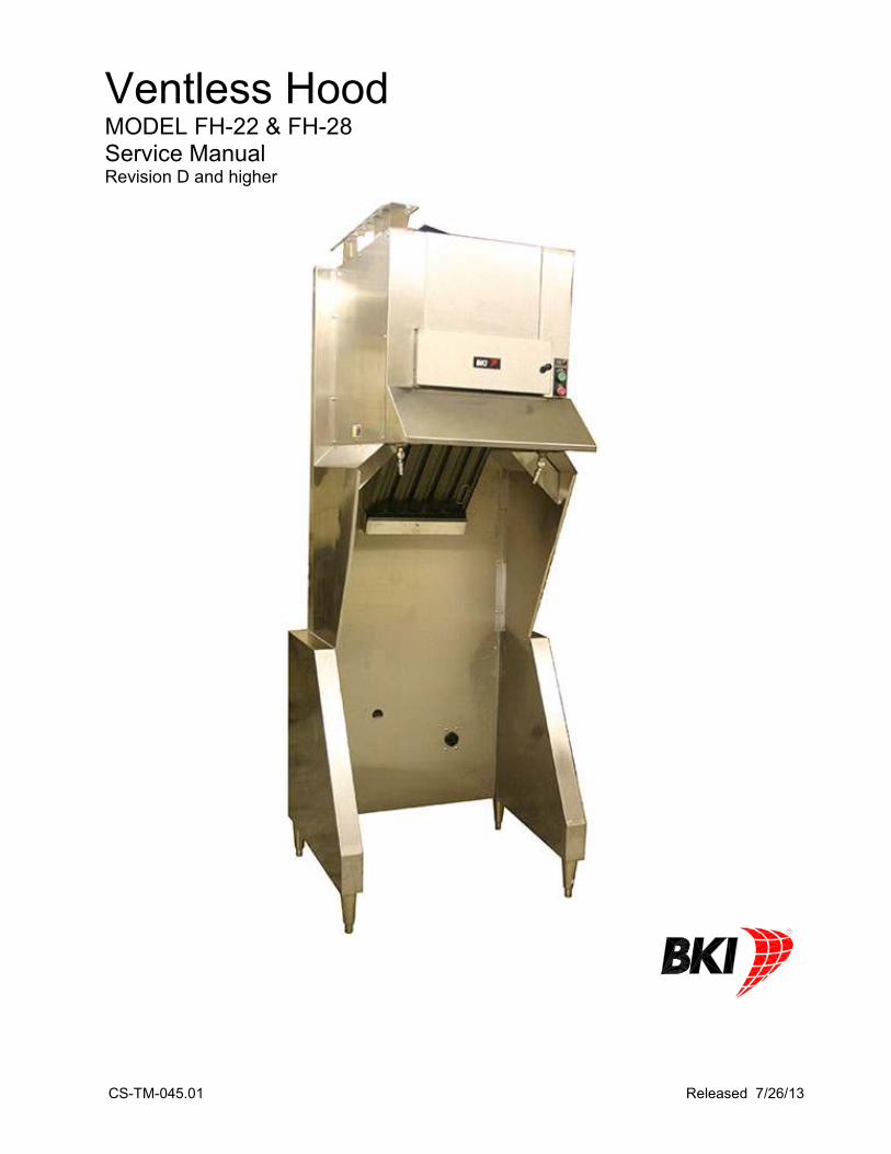
CS-TM-045.01 Released 7/26/13 Ventless Hood MODEL FH-22 & FH-28 Service Manual Revision D and higher
Transcript of MODEL FH-22 & FH-28 Service Manual - Parts...
CS-TM-045.01 Released 7/26/13
Ventless Hood MODEL FH-22 & FH-28 Service Manual Revision D and higher
CS-TM-045.01 Released 7/26/13
BKI LIMITED WARRANTY 2812 Grandview Dr. • Simpsonville, SC 29680 • USA
(864) 963-3471 • Toll Free: (800) 927-6887 • Fax: (864) 963-5316
WHAT IS COVERED This warranty covers defects in material and workmanship under normal use, and applies only to the
original purchaser providing that: � The equipment has not been accidentally or intentionally damaged, altered or misused;
� The equipment is properly installed, adjusted, operated and maintained in accordance with national
and local codes, and in accordance with the installation and operating instructions provided with this
product.
� The serial number rating plate affixed to the equipment has not been defaced or removed.
WHO IS COVERED This warranty is extended to the original purchaser and applies only to equipment purchased for use in the U.S.A.
COVERAGE PERIOD � Warranty claims must be received in writing by BKI within one (1) year from date of
installation or within one (1) year and three (3) months from data of shipment from the factory,
whichever comes first.
� COB Models: One (1) Year limited parts and labor.
� COM Models: Two (2) Year limited parts and labor. COM convection ovens also have a two (2) year
door warranty.
� Warranty period begins the date of dealer invoice to customer or ninety (90) days after
shipment date from BKI, whichever comes first.
WARRANTY COVERAGE This warranty covers on-site labor, parts and reasonable travel time and travel expenses of the authorized service representative up to (100) miles round trip and (2) hours travel time and performed during regular, weekday business hours.
EXCEPTIONS Any exceptions must be pre-approved in advance and in writing by BKI.
EXCLUSIONS � Negligence or acts of God, � Thermostat calibrations after (30) days from equipment installation date,
� Air and gas adjustments, � Light bulbs, � Glass doors and door adjustments, � Fuses,
� Adjustments to burner flames and cleaning of pilot burners, � Tightening of screws or fasteners, � Failures caused by erratic voltages or gas suppliers,
� Unauthorized repair by anyone other than a BKI Factory Authorized Service Center, � Damage in shipment, � Alteration, misuse or improper installation, � Thermostats and safety valves with broken capillary tubes,
� Freight – other than normal UPS charges, � Ordinary wear and tear, � Failure to follow installation and/or operating instructions, � Events beyond control of the company.
INSTALLATION Leveling, as well as proper installation and check out of all new equipment - per appropriate installation and use materials – is the responsibility of the dealer or installer, not the manufacturer.
REPLACEMENT PARTS BKI genuine Factory OEM parts receive a (90) day materials warranty effective from the date of installation by a BKI Factory Authorized Service Center.
Warranty is in lieu of all other warranties, expressed or implied, and all other obligations or liabilities on the manufacturer’s part. BKI shall in no event be liable for any special, indirect or consequential damages, or in any event for damages in excess of the purchase price of the unit. The repair or replacement of proven defective parts shall constitute a fulfillment of all obligations under the terms of this warranty.
Ventless Hood System Table of Contents
1
Table of Contents
Table of Contents ............................................................................................................................................. 1
Introduction ...................................................................................................................................................... 2 Safety Precautions ......................................................................................................................................... 2 Safety Signs and Messages ...................................................................................................................... 2 Specific Precautions .................................................................................................................................. 2 Safe Work Practices .................................................................................................................................. 3
UL Information ............................................................................................................................................... 5 Fusible Links .............................................................................................................................................. 5 Pressure/Open Fryers ............................................................................................................................... 5 Sandwich Grills .......................................................................................................................................... 5 Fryer Specifications ................................................................................................................................... 6 Griddles Specifications .............................................................................................................................. 6
Operation .......................................................................................................................................................... 7 Controls and Indicators .................................................................................................................................. 7 Hardware Controls..................................................................................................................................... 7
Start-Up .......................................................................................................................................................... 7 Shut-Down ..................................................................................................................................................... 7 When to Replace the Filter ............................................................................................................................ 7
Installation ........................................................................................................................................................ 8 Unpacking and Handling ................................................................................................................................ 8 Location and Clearance ............................................................................................................................ 8 Remove Front Brace ................................................................................................................................. 9 Leveling ..................................................................................................................................................... 9
Assembly ....................................................................................................................................................... 9 Fire Damper ............................................................................................................................................... 9 Air Deflector ............................................................................................................................................... 9 Particle/Odor Filter................................................................................................................................... 10 Appliance Stop (Used with BKI Automatic Lift Fryers) ............................................................................ 10 Appliance Restraining Device ................................................................................................................. 11 Fire Extinguishing System ....................................................................................................................... 12
Wiring Connection And Grounding .............................................................................................................. 14 General Guidelines .................................................................................................................................. 14
Mechanical Specifications ........................................................................................................................... 14
Maintenance ................................................................................................................................................... 15 Scheduled Maintenance .............................................................................................................................. 15 Cleaning the Grease Baffle ..................................................................................................................... 16 Replacing the Particle/Odor Filter ........................................................................................................... 16
Replacement Parts ......................................................................................................................................... 17
Accessories .................................................................................................................................................... 20
Wiring Diagram ............................................................................................................................................... 21
Notes ............................................................................................................................................................... 22
Ventless Hood System Introduction
2
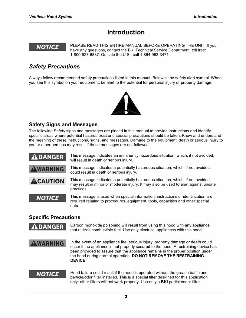
Introduction
PLEASE READ THIS ENTIRE MANUAL BEFORE OPERATING THE UNIT. If you have any questions, contact the BKI Technical Service Department, toll free: 1-800-927-6887. Outside the U.S., call 1-864-963-3471.
Safety Precautions Always follow recommended safety precautions listed in this manual. Below is the safety alert symbol. When you see this symbol on your equipment, be alert to the potential for personal injury or property damage.
Safety Signs and Messages The following Safety signs and messages are placed in this manual to provide instructions and identify specific areas where potential hazards exist and special precautions should be taken. Know and understand the meaning of these instructions, signs, and messages. Damage to the equipment, death or serious injury to you or other persons may result if these messages are not followed.
This message indicates an imminently hazardous situation, which, if not avoided, will result in death or serious injury.
This message indicates a potentially hazardous situation, which, if not avoided, could result in death or serious injury.
This message indicates a potentially hazardous situation, which, if not avoided, may result in minor or moderate injury. It may also be used to alert against unsafe practices.
This message is used when special information, instructions or identification are required relating to procedures, equipment, tools, capacities and other special data.
Specific Precautions
Carbon monoxide poisoning will result from using this hood with any appliance that utilizes combustible fuel. Use only electrical appliances with this hood.
In the event of an appliance fire, serious injury, property damage or death could occur if the appliance is not properly secured to the hood. A restraining device has been provided to assure that the appliance remains in the proper position under the hood during normal operation. DO NOT REMOVE THE RESTRAINING DEVICE!
Hood failure could result if the hood is operated without the grease baffle and particle/odor filter installed. This is a special filter designed for this application only; other filters will not work properly. Use only a BKI particle/odor filter.
Ventless Hood System Introduction
3
Safe Work Practices
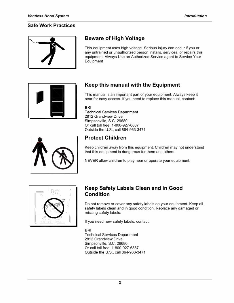
Beware of High Voltage This equipment uses high voltage. Serious injury can occur if you or any untrained or unauthorized person installs, services, or repairs this equipment. Always Use an Authorized Service agent to Service Your Equipment
Keep this manual with the Equipment This manual is an important part of your equipment. Always keep it near for easy access. If you need to replace this manual, contact: BKI Technical Services Department 2812 Grandview Drive Simpsonville, S.C. 29680 Or call toll free: 1-800-927-6887 Outside the U.S., call 864-963-3471
Protect Children Keep children away from this equipment. Children may not understand that this equipment is dangerous for them and others. NEVER allow children to play near or operate your equipment.
Keep Safety Labels Clean and in Good Condition Do not remove or cover any safety labels on your equipment. Keep all safety labels clean and in good condition. Replace any damaged or missing safety labels. If you need new safety labels, contact: BKI Technical Services Department 2812 Grandview Drive Simpsonville, S.C. 29680 Or call toll free: 1-800-927-6887 Outside the U.S., call 864-963-3471
Ventless Hood System Introduction
4
911
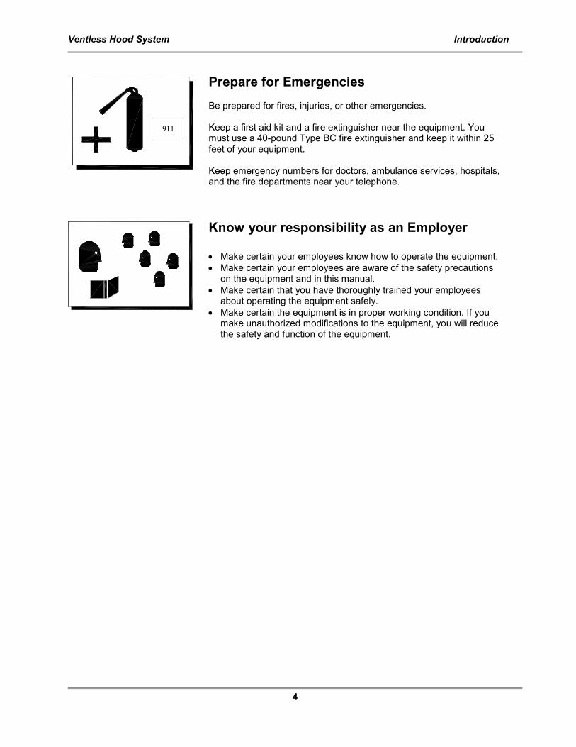
Prepare for Emergencies Be prepared for fires, injuries, or other emergencies. Keep a first aid kit and a fire extinguisher near the equipment. You must use a 40-pound Type BC fire extinguisher and keep it within 25 feet of your equipment. Keep emergency numbers for doctors, ambulance services, hospitals, and the fire departments near your telephone.
Know your responsibility as an Employer • Make certain your employees know how to operate the equipment.
• Make certain your employees are aware of the safety precautions on the equipment and in this manual.
• Make certain that you have thoroughly trained your employees about operating the equipment safely.
• Make certain the equipment is in proper working condition. If you make unauthorized modifications to the equipment, you will reduce the safety and function of the equipment.
Ventless Hood System Introduction
5
UL Information
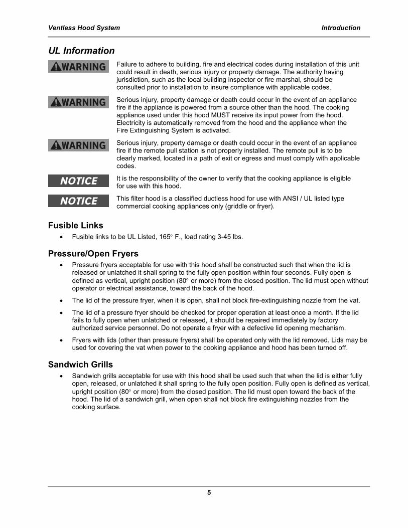
Failure to adhere to building, fire and electrical codes during installation of this unit could result in death, serious injury or property damage. The authority having jurisdiction, such as the local building inspector or fire marshal, should be consulted prior to installation to insure compliance with applicable codes.
Serious injury, property damage or death could occur in the event of an appliance fire if the appliance is powered from a source other than the hood. The cooking appliance used under this hood MUST receive its input power from the hood. Electricity is automatically removed from the hood and the appliance when the Fire Extinguishing System is activated.
Serious injury, property damage or death could occur in the event of an appliance fire if the remote pull station is not properly installed. The remote pull is to be clearly marked, located in a path of exit or egress and must comply with applicable codes.
It is the responsibility of the owner to verify that the cooking appliance is eligible for use with this hood.
This filter hood is a classified ductless hood for use with ANSI / UL listed type commercial cooking appliances only (griddle or fryer).
Fusible Links
• Fusible links to be UL Listed, 165° F., load rating 3-45 lbs.
Pressure/Open Fryers
• Pressure fryers acceptable for use with this hood shall be constructed such that when the lid is released or unlatched it shall spring to the fully open position within four seconds. Fully open is
defined as vertical, upright position (80° or more) from the closed position. The lid must open without operator or electrical assistance, toward the back of the hood.
• The lid of the pressure fryer, when it is open, shall not block fire-extinguishing nozzle from the vat.
• The lid of a pressure fryer should be checked for proper operation at least once a month. If the lid fails to fully open when unlatched or released, it should be repaired immediately by factory authorized service personnel. Do not operate a fryer with a defective lid opening mechanism.
• Fryers with lids (other than pressure fryers) shall be operated only with the lid removed. Lids may be used for covering the vat when power to the cooking appliance and hood has been turned off.
Sandwich Grills
• Sandwich grills acceptable for use with this hood shall be used such that when the lid is either fully open, released, or unlatched it shall spring to the fully open position. Fully open is defined as vertical,
upright position (80° or more) from the closed position. The lid must open toward the back of the hood. The lid of a sandwich grill, when open shall not block fire extinguishing nozzles from the cooking surface.
Ventless Hood System Introduction
6
Fryer Specifications
Volts 208/240
Phase 1 or 3
Maximum Amps 60
Maximum Input 22 KW (3ph) 14.4 KW (1ph)
Frequency 60 Hz
Maximum normal frying temperature 375° F. (191° C.)
Maximum shortening capacity 110 lbs. (50kg.)
Maximum cooking surface area 396 sq. in. (2555 sq. cm.)
USE ELECTRIC FRYERS AND SINGLE VAT FRYERS ONLY
Griddles Specifications
Volts 208/240
Phase 1 or 3
Maximum Amps 38.5
Maximum Input 8 KW
Frequency 60 Hz
Maximum griddle surface area 450 sq. in. (2903 sq. cm.)
Maximum cooking surface temperature 450° F. (232° C.)
USE ELECTRIC GRIDDLES ONLY
Ventless Hood System Operation
7
Operation
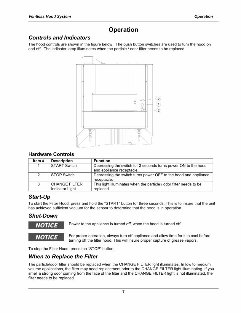
Controls and Indicators The hood controls are shown in the figure below. The push button switches are used to turn the hood on and off. The indicator lamp illuminates when the particle / odor filter needs to be replaced.
Hardware Controls
Item # Description Function
1 START Switch Depressing the switch for 3 seconds turns power ON to the hood and appliance receptacle.
2 STOP Switch Depressing the switch turns power OFF to the hood and appliance receptacle.
3 CHANGE FILTER Indicator Light
This light illuminates when the particle / odor filter needs to be replaced.
Start-Up To start the Filter Hood, press and hold the “START” button for three seconds. This is to insure that the unit has achieved sufficient vacuum for the sensor to determine that the hood is in operation.
Shut-Down
Power to the appliance is turned off, when the hood is turned off.
For proper operation, always turn off appliance and allow time for it to cool before turning off the filter hood. This will insure proper capture of grease vapors.
To stop the Filter Hood, press the “STOP” button.
When to Replace the Filter
The particle/odor filter should be replaced when the CHANGE FILTER light illuminates. In low to medium volume applications, the filter may need replacement prior to the CHANGE FILTER light illuminating. If you smell a strong odor coming from the face of the filter and the CHANGE FILTER light is not illuminated, the filter needs to be replaced.
CHANGEFILTER
START
ST0P
1
2
3
Ventless Hood System Installation
8
Installation
Serious injury, equipment damage or death could result if attempting to install this unit yourself. Ensure that an authorized BKI service agent installs the unit.
Unpacking and Handling
The company taking delivery of this equipment is responsible for filling all freight claims with the delivering truck line. Inspect all cartons and crates for damage as soon as they arrive. If damage to cartons or crates is found, or if a shortage is found, note this on the bill of lading (all copies) prior to signing.
If damage is found when the equipment is opened, immediately call the delivering truck line and follow up the call with a written report indicating concealed damage to your shipment. Ask for an immediate inspection of your concealed damage item. Packaging material MUST be retained to show the inspector from the truck line.
Move the merchandiser as close as possible to its permanent location before moving the merchandiser off of the shipping pallet.
Make certain there are no separately packed accessories before discarding packaging.
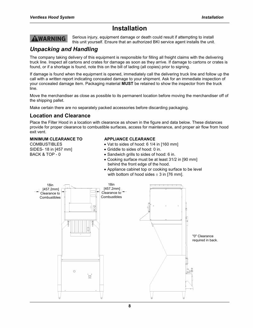
Location and Clearance
Place the Filter Hood in a location with clearance as shown in the figure and data below. These distances provide for proper clearance to combustible surfaces, access for maintenance, and proper air flow from hood exit vent.
MINIMUM CLEARANCE TO APPLIANCE CLEARANCE
COMBUSTIBLES • Vat to sides of hood: 6 1/4 in [160 mm]
SIDES- 18 in [457 mm] • Griddle to sides of hood: 0 in.
BACK & TOP - 0 • Sandwich grills to sides of hood: 6 in.
• Cooking surface must be at least 31/2 in [90 mm] behind the front edge of the hood.
• Appliance cabinet top or cooking surface to be level
with bottom of hood sides ± 3 in [76 mm].
18in
[457.2mm]
Clearance to
Combustibles
18in
[457.2mm]
Clearance to
Combustibles
"0" Clearance
required in back.
Ventless Hood System Installation
9
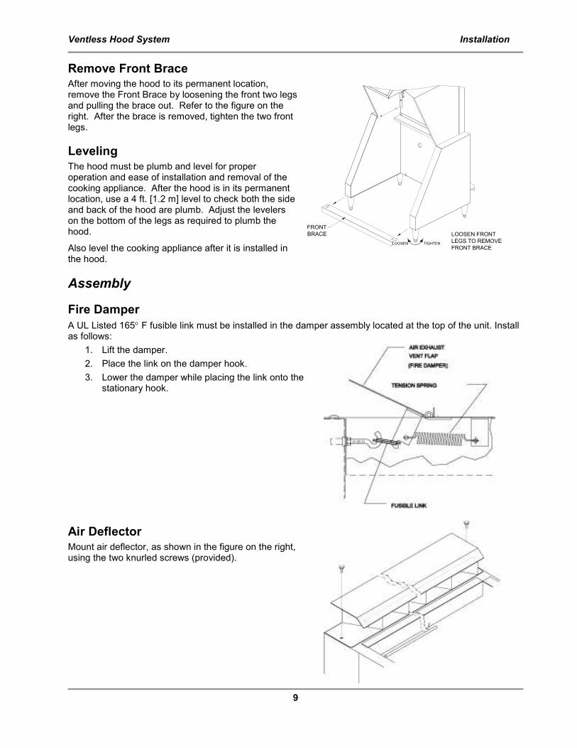
Remove Front Brace After moving the hood to its permanent location, remove the Front Brace by loosening the front two legs and pulling the brace out. Refer to the figure on the right. After the brace is removed, tighten the two front legs.
Leveling
The hood must be plumb and level for proper operation and ease of installation and removal of the cooking appliance. After the hood is in its permanent location, use a 4 ft. [1.2 m] level to check both the side and back of the hood are plumb. Adjust the levelers on the bottom of the legs as required to plumb the hood.
Also level the cooking appliance after it is installed in the hood.
Assembly
Fire Damper
A UL Listed 165° F fusible link must be installed in the damper assembly located at the top of the unit. Install as follows:
1. Lift the damper.
2. Place the link on the damper hook.
3. Lower the damper while placing the link onto the stationary hook.
Air Deflector
Mount air deflector, as shown in the figure on the right, using the two knurled screws (provided).
FRONT
BRACE LOOSEN FRONT
LEGS TO REMOVE
FRONT BRACELOOSEN TIGHTEN
Ventless Hood System Installation
10
Particle/Odor Filter 1. Remove the filter from the plastic bag.
2. Open the filter door on the front of the unit by rotating the handle counter-clockwise.
3. Observing the “UP” arrows on the filter, with a hand at each front corner, carefully slide the filter into the unit.
4. Close and latch the door.
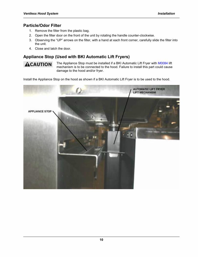
Appliance Stop (Used with BKI Automatic Lift Fryers)
The Appliance Stop must be installed if a BKI Automatic Lift Fryer with M0084 lift mechanism is to be connected to the hood. Failure to install this part could cause damage to the hood and/or fryer.
Install the Appliance Stop on the hood as shown if a BKI Automatic Lift Fryer is to be used to the hood.
Ventless Hood System Installation
11
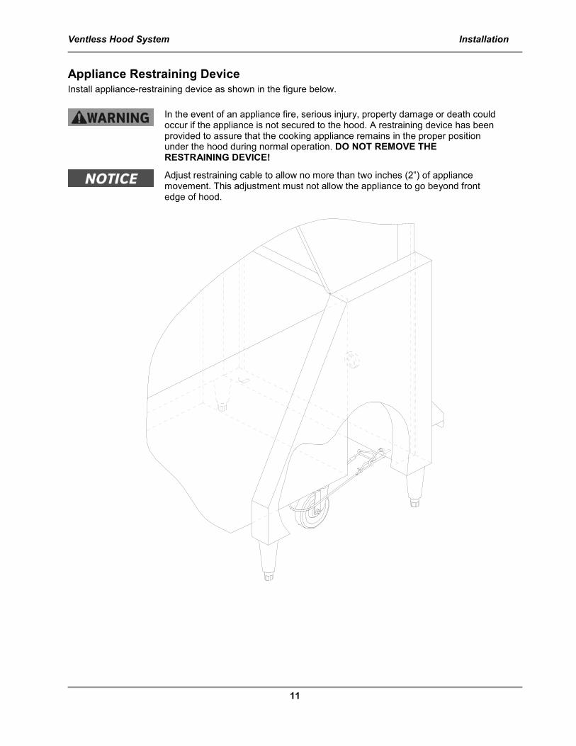
Appliance Restraining Device Install appliance-restraining device as shown in the figure below.
In the event of an appliance fire, serious injury, property damage or death could occur if the appliance is not secured to the hood. A restraining device has been provided to assure that the cooking appliance remains in the proper position under the hood during normal operation. DO NOT REMOVE THE RESTRAINING DEVICE!
Adjust restraining cable to allow no more than two inches (2”) of appliance movement. This adjustment must not allow the appliance to go beyond front edge of hood.
Ventless Hood System Installation
12
Fire Extinguishing System
In the event of an appliance fire, serious injury, property damage or death could occur if any part of the appliance obstructs the spray nozzles. Ensure that lids and/or other parts of the appliance do not obstruct the spray pattern of either nozzle.
The fire extinguishing system components used in this hood have been evaluated by U.L. in the course of their classification for use on this hood.
An authorized Range Guard distributor must install and activate the filter hood
fire extinguishing system. To locate an authorized Range Guard Distributor use the following contact information: Ronald Woodward Technical Service Specialist Badger Fire Protection 4251 Seminole Trail Charlottesville Va. 22911 Office: 800-446-3857 ext. 111 Fax: 434-974-4113 Mobile: 434-981-0505
1. After the hood has been properly secured to prevent movement, locate the end-of-line remote pull
station (at a point of egress or exit) in a manner approved by the local authority and in accordance
with applicable codes. To install the end-of-line remote, use ½” EMT and Range Guard corner pulleys #97915.
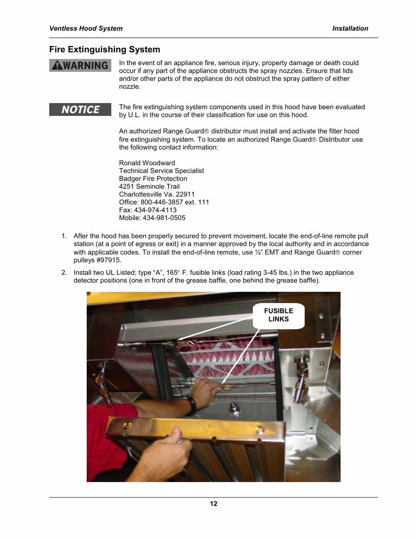
2. Install two UL Listed; type “A”, 165° F. fusible links (load rating 3-45 lbs.) in the two appliance detector positions (one in front of the grease baffle, one behind the grease baffle).
FUSIBLE
LINKS
Ventless Hood System Installation
13
3. If required, connect the provided fire extinguishing system contacts for remote signaling (refer to the electrical diagram in this manual).
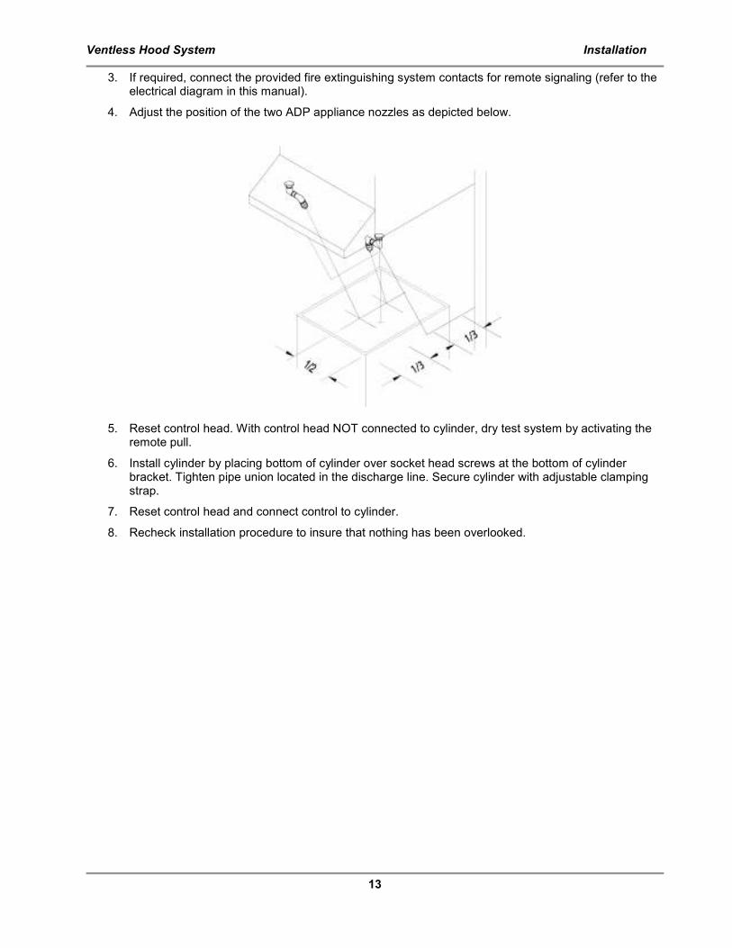
4. Adjust the position of the two ADP appliance nozzles as depicted below.
5. Reset control head. With control head NOT connected to cylinder, dry test system by activating the remote pull.
6. Install cylinder by placing bottom of cylinder over socket head screws at the bottom of cylinder bracket. Tighten pipe union located in the discharge line. Secure cylinder with adjustable clamping strap.
7. Reset control head and connect control to cylinder.
8. Recheck installation procedure to insure that nothing has been overlooked.
Ventless Hood System Installation
14
REMOTE ALARM
CONNECTION
HERE
ELECTRICAL
ENTRY KNOCK
OUTS
CONTACTOR
Wiring Connection And Grounding
Electrocution, equipment failure or property damage could result if an unlicensed electrician performs the electrical installation. Ensure that a licensed electrician perform the electrical installation in accordance with local codes, or in the absence of local codes, with the National Electrical Code, ANSI NFPA 70-20XX.
General Guidelines
In the absence of local codes refer to the latest edition of the National Electrical Code, ANSI/NFPA 70-20XX (USA).
Verify that the power supply conforms to the electrical rating listed on the appliance data plate.
Ensure that the appliance is grounded (earthed).
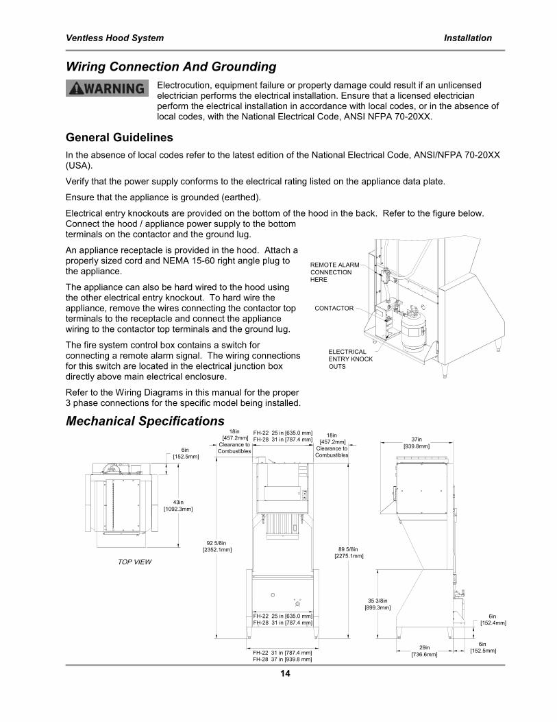
Electrical entry knockouts are provided on the bottom of the hood in the back. Refer to the figure below. Connect the hood / appliance power supply to the bottom terminals on the contactor and the ground lug.
An appliance receptacle is provided in the hood. Attach a properly sized cord and NEMA 15-60 right angle plug to the appliance.
The appliance can also be hard wired to the hood using the other electrical entry knockout. To hard wire the appliance, remove the wires connecting the contactor top terminals to the receptacle and connect the appliance wiring to the contactor top terminals and the ground lug.
The fire system control box contains a switch for connecting a remote alarm signal. The wiring connections for this switch are located in the electrical junction box directly above main electrical enclosure.
Refer to the Wiring Diagrams in this manual for the proper 3 phase connections for the specific model being installed.
Mechanical Specifications
FH-22 31 in [787.4 mm]
FH-28 37 in [939.8 mm]
FH-22 25 in [635.0 mm]
FH-28 31 in [787.4 mm]
FH-22 25 in [635.0 mm]
FH-28 31 in [787.4 mm]
92 5/8in
[2352.1mm] 89 5/8in
[2275.1mm]
18in
[457.2mm]
Clearance to
Combustibles
18in
[457.2mm]
Clearance to
Combustibles6in
[152.5mm]
43in
[1092.3mm]
6in
[152.4mm]
35 3/8in
[899.3mm]
29in
[736.6mm]
6in
[152.5mm]
37in
[939.8mm]
Ventless Hood System Maintenance
15
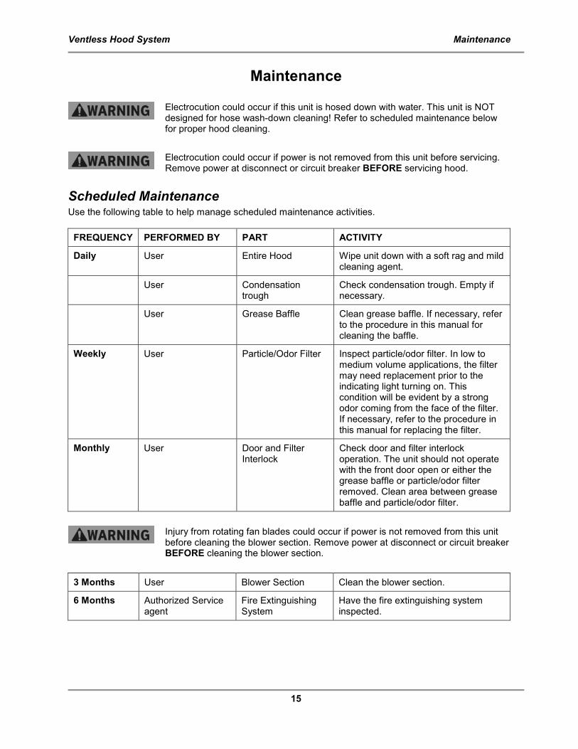
Maintenance
Electrocution could occur if this unit is hosed down with water. This unit is NOT designed for hose wash-down cleaning! Refer to scheduled maintenance below for proper hood cleaning.
Electrocution could occur if power is not removed from this unit before servicing. Remove power at disconnect or circuit breaker BEFORE servicing hood.
Scheduled Maintenance Use the following table to help manage scheduled maintenance activities.
FREQUENCY PERFORMED BY PART ACTIVITY
Daily User Entire Hood Wipe unit down with a soft rag and mild cleaning agent.
User Condensation trough
Check condensation trough. Empty if necessary.
User Grease Baffle Clean grease baffle. If necessary, refer to the procedure in this manual for cleaning the baffle.
Weekly User Particle/Odor Filter Inspect particle/odor filter. In low to medium volume applications, the filter may need replacement prior to the indicating light turning on. This condition will be evident by a strong odor coming from the face of the filter. If necessary, refer to the procedure in this manual for replacing the filter.
Monthly User Door and Filter Interlock
Check door and filter interlock operation. The unit should not operate with the front door open or either the grease baffle or particle/odor filter removed. Clean area between grease baffle and particle/odor filter.
Injury from rotating fan blades could occur if power is not removed from this unit before cleaning the blower section. Remove power at disconnect or circuit breaker BEFORE cleaning the blower section.
3 Months User Blower Section Clean the blower section.
6 Months Authorized Service agent
Fire Extinguishing System
Have the fire extinguishing system inspected.
Ventless Hood System Maintenance
16
Cleaning the Grease Baffle
1. Shut down the unit.
2. Locate the thumbscrews and retaining frame at the top of the grease baffle.
3. With one hand, hold the baffle to prevent it from dropping. With the other hand, loosen the thumbscrews and slide the retaining frame forward.
4. Slowly lower the top end of the baffle until it clears the retaining frame.
5. Spray the grease baffle with degreasing type soap.
6. Rinse with hot water; dry, and replace in hood.
Replacing the Particle/Odor Filter
1. Shut down the unit.
2. Open the filter door on the front of the unit by rotating the handle counter-clockwise.
3. Slide the used filter out of the unit.
4. Remove the replacement filter from the plastic bag.
5. Observing the “UP” arrows on the filter, with a hand at each front corner, carefully slide the filter into the unit.
When installing a new filter, slight resistance should be observed as the filter is being slid into place. This resistance is generated by four (4) filter springs located on the bottoms of the filter slides. These springs insure a proper seal at the top of the filter. After a period of time it may become necessary to adjust the pressure that these springs provide by lifting them slightly with your fingers.
6. Close and latch the door.
Ventless Hood System Replacement Parts
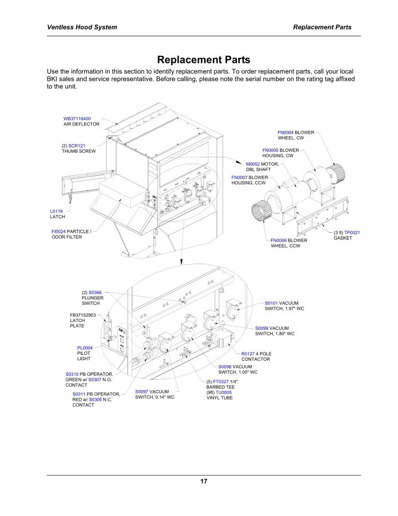
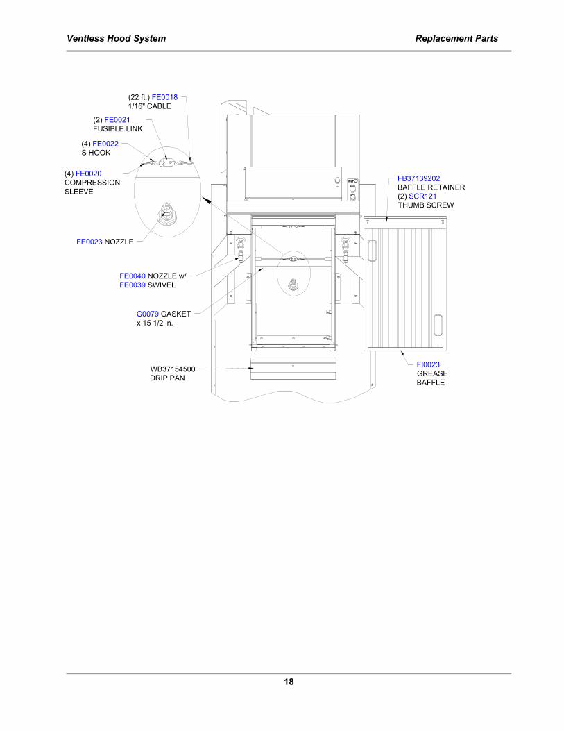
17
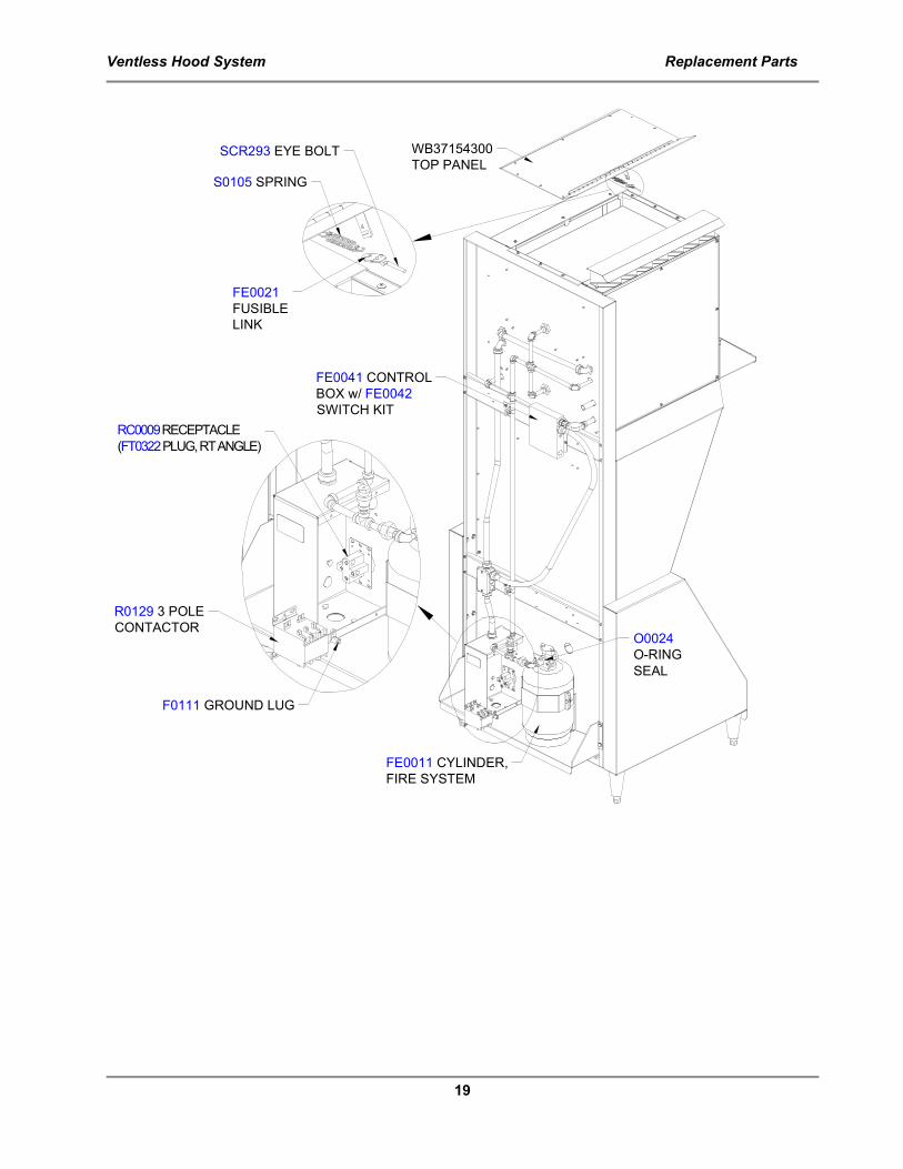
Replacement Parts Use the information in this section to identify replacement parts. To order replacement parts, call your local BKI sales and service representative. Before calling, please note the serial number on the rating tag affixed to the unit.
PL0004
PILOT
LIGHT
FB37152903
LATCH
PLATE
(2) S0366
PLUNGER
SWITCH
S0310 PB OPERATOR,
GREEN w/ S0307 N.O.
CONTACT
S0311 PB OPERATOR,
RED w/ S0306 N.C.
CONTACT
R0127 4 POLE
CONTACTOR
S0098 VACUUM
SWITCH, 1.00" WC
S0097 VACUUM
SWITCH, 0.14" WC
S0099 VACUUM
SWITCH, 1.80" WC
S0101 VACUUM
SWITCH, 1.97" WC
(5) FT0327 1/4"
BARBED TEE
(9ft) TU0005
VINYL TUBE
L0119
LATCH
FI0024 PARTICLE /
ODOR FILTER
WB37116400
AIR DEFLECTOR
(2) SCR121
THUMB SCREW
FN0006 BLOWER
WHEEL, CCW
FN0004 BLOWER
WHEEL, CW
FN0005 BLOWER
HOUSING, CW
FN0007 BLOWER
HOUSING, CCW
M0052 MOTOR,
DBL SHAFT
(3 ft) TP0021
GASKET
Ventless Hood System Replacement Parts
18
FI0023
GREASE
BAFFLE
FB37139202
BAFFLE RETAINER
(2) SCR121
THUMB SCREW
G0079 GASKET
x 15 1/2 in.
FE0040 NOZZLE w/
FE0039 SWIVEL
FE0023 NOZZLE
(2) FE0021
FUSIBLE LINK
(4) FE0022
S HOOK
(4) FE0020
COMPRESSION
SLEEVE
(22 ft.) FE0018
1/16" CABLE
WB37154500
DRIP PAN
Ventless Hood System Replacement Parts
19
FE0041 CONTROL
BOX w/ FE0042
SWITCH KIT
FE0011 CYLINDER,
FIRE SYSTEM
O0024
O-RING
SEAL
RC0009 RECEPTACLE
(FT0322 PLUG, RT ANGLE)
R0129 3 POLE
CONTACTOR
F0111 GROUND LUG
WB37154300
TOP PANEL
S0105 SPRING
FE0021
FUSIBLE
LINK
SCR293 EYE BOLT
Ventless Hood System Accessories
20
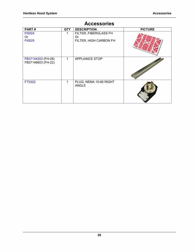
Accessories PART # QTY DESCRIPTION PICTURE
FI0024 Or FI0025
1 FILTER, FIBERGLASS FH Or FILTER, HIGH CARBON FH
FB37144203 (FH-28) FB37146603 (FH-22)
1 APPLIANCE STOP
FT0322 1 PLUG, NEMA 15-60 RIGHT
ANGLE
Ventless Hood System Wiring Diagram
21
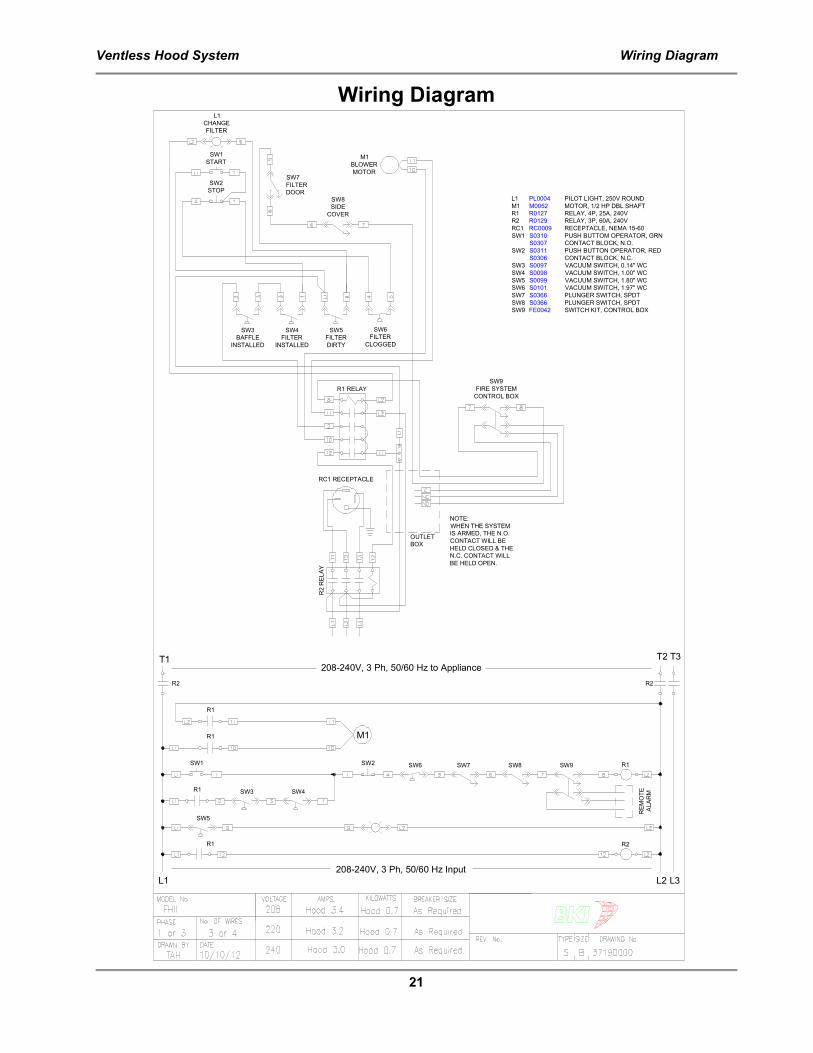
Wiring Diagram
SW1 SW2 SW6
SW3 SW4R1
SW5
SW7 SW8 SW9
REMOTE
ALARM
R1
R1
M1
R1
L1 L2
208-240V, 3 Ph, 50/60 Hz Input
R1
R2
L3
R2R2
208-240V, 3 Ph, 50/60 Hz to ApplianceT1 T2 T3
SW1
START
SW2
STOP
L1
CHANGE
FILTER
SW3
BAFFLE
INSTALLED
SW4
FILTER
INSTALLED
SW5
FILTER
DIRTY
SW6
FILTER
CLOGGED
SW9
FIRE SYSTEM
CONTROL BOX
SW7
FILTER
DOORSW8
SIDE
COVER
M1
BLOWER
MOTOR
OUTLET
BOX
NOTE:
WHEN THE SYSTEM
IS ARMED, THE N.O.
CONTACT WILL BE
HELD CLOSED & THE
N.C. CONTACT WILL
BE HELD OPEN.
R1 RELAY
R2 RELAY
RC1 RECEPTACLE
L1 PL0004 PILOT LIGHT, 250V ROUND
M1 M0052 MOTOR, 1/2 HP DBL SHAFT
R1 R0127 RELAY, 4P, 25A, 240V
R2 R0129 RELAY, 3P, 60A, 240V
RC1 RC0009 RECEPTACLE, NEMA 15-60
SW1 S0310 PUSH BUTTOM OPERATOR, GRN
S0307 CONTACT BLOCK, N.O.
SW2 S0311 PUSH BUTTON OPERATOR, RED
S0306 CONTACT BLOCK, N.C.
SW3 S0097 VACUUM SWITCH, 0.14" WC
SW4 S0098 VACUUM SWITCH, 1.00" WC
SW5 S0099 VACUUM SWITCH, 1.80" WC
SW6 S0101 VACUUM SWITCH, 1.97" WC
SW7 S0366 PLUNGER SWITCH, SPDT
SW8 S0366 PLUNGER SWITCH, SPDT
SW9 FE0042 SWITCH KIT, CONTROL BOX
Ventless Hood System Notes
CS-TM-045.01 Released 7/26/13
Notes
2812 Grandview Dr., Simpsonville, S.C. 29680, USA http://www.bkideas.com Made and printed in the U.S.A.


![Ze]bki dajp`daflm - Wing On Travel · tg NJKP fh+oCtJ \A0hK zxBK{ `?J @=:76-1 zFK4z8ER*:0{z9:8](https://static.fdocuments.in/doc/165x107/6030ce177417fe6f386af2cc/zebki-dajpdaflm-wing-on-travel-tg-njkp-fhoctj-a0hk-zxbk-j-76-1-zfk4z8er0z98.jpg)