MODEL EMAX 25M - Distribution JPB€¦ · MODEL EMAX 25M 60 MOWER AND ... INSTALLATION INSTRUCTIONS...
52
MHM665 NO. 031622 01/14 SERIAL NUMBER MAX25M-1001 AND LATER MODEL EMAX 25M 60” MOWER AND MOUNTING FOR EMAX 22 and EMAX 25 SERIES TRACTORS INCLUDES OPERATOR’S MANUAL, INSTALLATION INSTRUCTIONS AND PARTS CATALOG
Transcript of MODEL EMAX 25M - Distribution JPB€¦ · MODEL EMAX 25M 60 MOWER AND ... INSTALLATION INSTRUCTIONS...

MHM665NO. 031622 01/14
SERIAL NUMBER MAX25M-1001 AND LATER
MODEL EMAX 25M60” MOWER AND MOUNTING
FOR EMAX 22 and EMAX 25 SERIES TRACTORS
INCLUDES OPERATOR’S MANUAL,INSTALLATION INSTRUCTIONS AND PARTS CATALOG

2

3
Warranty Coverage:
Mahindra, Ltd, Inc., herein referred to as Mahindra, undertakes to replace or repair any part of a Mahindra mower deck where damage has been proven to be caused by defects in material or workmanship.
This Warranty is valid for a period of 2 years for mower deck components from the date of the original retail sale. Parts replaced or repaired under the terms of this Warranty are guaranteed only until the original warranty expires.
It is further understood and agreed that the defect should be immediately reported to the Selling Dealer. The Selling Dealer will generally perform Warranty repairs or replacements and the Purchaser shall deliver the Mahindra Mower Deck to the Dealer’s place of business for repair. In the event Purchaser is located more than 75 miles from the Selling Dealer, any Mahindra Dealer authorized to sell and service Mahindra Products may perform the repair at its dealership.
The obligation of Mahindra to the Purchaser under this Warranty is limited to the repair or replacement ofdefective parts by an authorized Mahindra dealer. Repair or replacement in accordance with this Warranty shall constitute fulfillment of all liabilities of Mahindra and the Selling Dealer in respect to Mahindra Mower Decks.
There are no warranties beyond those which expressly appear herein. Any implied warranty ofmerchantability or fitness for a particular purpose is specifically excluded here from.
Warranty Provisions:
Mahindra’s liability under this Warranty is subject to the observance by the Purchaser of the following provisions:• The purchaser shall at all times in the operation of any Mahindra Product, use those brands and grades of
lubricating oils, lubricants and spare parts officially approved by Mahindra.• The Mahindra Mower Decks shall have been used in accordance with the procedures specified in the Operator’s
Manual. This Warranty does not extend to damage resulting from misapplication, abuse, misuse, failure to perform maintenance, negligence, fire, accidents or changes or faulty mounting carried out by the Purchaser. When making a Warranty exchange of parts, the Purchaser shall compensate Mahindra for the time that the parts have been used if they have been exposed to extreme wear.
• Compensation is not paid for physical harm, deadlock, resulting damages, or other losses.• To obtain warranty service, the Purchaser must (1) report the product defect to an authorized Mahindra dealer
and request repair within the applicable warranty term and (2) present evidence of purchase or date of original use.
• The Warranty shall be void if the Mahindra Mower Deck has been altered or repaired outside of a Mahindra dealership in a manner, which, in the sole judgment of Mahindra, affects its performance, stability, or reliability.
• The customer shall be responsible for transportation expenses for the Mahindra Mower Deck to the dealership or travel of dealer personnel to customer location for Warranty repair. The customer shall also pay any premium for overtime labor requested by the customer.
• Temporary repairs or additional costs due to the work being performed after normal working hours will not be compensated.
• The above warranty is in lieu of all other warranties on Mahindra’s behalf and neither party assumes any other liability in connection with Mahindra’s Products.
• Any dispute arising between Mahindra and the Purchaser concerning the liability of Mahindra under this warranty shall be subject to the laws of the State of Texas.
Right To Make Design and Product Changes:
Mahindra reserves the right to make changes in the design and other changes in its Mahindra Products at any time without incurring any obligation with respect to any product previously ordered, sold or shipped.
WARRANTY CONDITIONS

4
DEALER PREPARATION CHECK LIST
BEFORE DELIVERING MACHINE:The following check list should be completed.Use the Operator’s Manual as a guide.
Before operating mower deck, check that your Dealer has covered the following information with you:
_____Equipment has been completely assembled as directed._____Equipment has been functionally tested for proper operation._____All safety decals are readable (see decal pages)._____Purchaser has been instructed in proper & safe operating methods: _____Operators Safety Precautions _____Tractor Wheel Tread-Tire & Inflation Recommendations _____Proper Mower Deck Operation _____Mower Deck Dismounting _____Mower Deck Mounting _____Lubrication - Service Care _____Storage_____Warranty Coverage & Operators Manual explained to purchaser._____Operators Manual has been delivered to purchaser.
Dealer’s Signature __________________________________________________________________________
CAUTION: It is recommended that the tractor be equipped with Rollover Protection System(ROPS) and seat belt be used for all implement operations.
NOTE: This checklist is to remain in owner’s manual.It is the responsibility of the dealer to complete the procedures listed above before delivery of thisimplement to the customer.

5
CONGRATULATIONS
You are now the proud owner of a MAHINDRA EMAX 25M Mower Deck. This mower deck is a product of quality en-gineering and manufacturing. It is made of fine materials and under a rigid quality control system. It will give you long, satisfactory service. To obtain the best use of your mower deck, please read this manual carefully. It will help you be-come familiar with the operation of the mower deck and contains many helpful hints about mower deck maintenance. The immediate use of new techniques in the manufacture of products may cause some small parts of this manual to be outdated. Mahindra dealers will have the most up-to-date information. Please do not hesitate to consult with them.
Because Mahindra maintains an ongoing program of product improvement, we reserve the right to make improve-ments in design or changes in specifications without incurring any obligation to install them on units previously sold.
Because of the possibility that some photographs in this manual were taken of prototype models, production models may vary in some detail. In addition, some photographs may show shields removed for purposes of clarity. Never operate this implement without all shields in place.
RETAIL CUSTOMER’S RESPONSIBILITYUNDER THE MAHINDRA WARRANTY
It is the Retail Customer and/or Operator’s responsibility to read the Operator’s Manual, to operate, lubricate, main-tain, and store the product in accordance with all instructions and safety procedures. Failure of the operator to read the Operator’s Manual is a misuse of this equipment.
It is the Retail Customer and/or Operator’s responsibility to inspect the product and to have any part(s) repaired or replaced when continued operation would cause damage or excessive wear to other parts or cause a safety hazard.
It is the Retail Customer’s responsibility to deliver the product to the authorized Mahindra dealer from whom he purchased it, for service or replacement of defective parts which are covered by warranty. Repairs to be submitted for warranty consideration must be made within forty-five (45) days of failure.
It is the Retail Customer’s responsibility for any cost incurred by the Dealer for traveling to or hauling of the product for the purpose of performing a warranty obligation or inspection.

6
IMPORTANT SAFETY PRECAUTIONS
UNDERSTAND SIGNAL WORDS
DANGER indicates a hazardous situation which, if not avoided, will result in death or serious injury.
WARNING indicates a hazardous situation which, if not avoided, could result in death or serious injury.
CAUTION indicates a hazardous situation which, if not avoided, could result in minor or moderate injury.
NOTICE is used to address practices not related to physical injury.
SAFETY ALERT SYMBOL This is the safety alert symbol. It is used to alert you to potential physical injury hazards. Obey all safety messages that follow this symbol to avoid possible injury or death.
In addition to the design and configuration of equipment, hazard control and accident prevention are dependent upon the awareness, concern, prudence and proper training of personnel in the operation, transport, maintenance and storage of equipment. Lack of attention to safety can result in accident, personal injury, reduction of efficiency and worst of all – loss of life. Watch for safety hazards and correct deficiencies promptly. Use the following safety precautions as a general guide to safe operations when using this machine. Additional safety precautions are used throughout this manual for specific operating and maintenance procedures. Read this manual and review the safety precautions often until you know the limitations. Do not allow children or untrained persons to operate equipment. Do not operate equipment under the influence of drugs or alcohol.
THE TRACTOR
1. Read, understand and follow all instructions in the manual and on the machine before starting. Failure to do so could result in serious injury or death and equipment damage. Keep this manual in a safe place for future and regular reference and for ordering service parts.
2. Read and understand all Safety Precautions in the Tractor Operator’s Manual.
3. Allow only responsible operators familiar with the instructions to operate the machine. Know the controls and how to stop tractor engine and mower quickly in an emergency.
4. Tractor must be equipped with Rollover Protective System (ROPS) and seat belt for all mower operations. Keep foldable ROPS systems locked in the up position at all times when operating the mower. Falling off or overturning a tractor can result in death from being run over or crushed.
5. Always wear seat belt on Rollover Protective System (ROPS) equipped tractors. Do not wear a seat belt if the tractor Rollover Protective System (ROPS) has been removed.
6. Wear personal protective equipment (PPE), such as, but not limited to, protection for eyes, ears, lungs, head, hair, hands and feet when operating, servicing, or repairing the equipment. Avoid wearing loose clothing or jewelry that may catch and entangle on equipment moving parts.
7. Stop tractor engine, place transmission in park (or neutral), engage parking brake, lower mower deck to ground, allow machine moving parts to stop, remove ignition key to prevent unauthorized person from starting tractor before servicing, repairing, or making adjustments to the equipment.
8. Never leave the tractor seat with the mower blades rotating, with the tractor in motion, or the engine running.
9. Use fender hand holds and steps when mounting and dismounting tractor to prevent falls. Keep steps and Operator’s platform clean and free of debris.

7
10. All tractor three point hitch components and hardware must be tightened to proper specifications to avoid damage to tractor or mower prior to operation. Please review tractor Operator’s Manual or consult your local dealer for proper torque and tightening specifications of tractor three point hitch components.
11. Move and turn the tractor at low speeds. Avoid erratic operation and excessive speed.
12. Keep the tractor in gear when traveling down hill.
13. Do not mow near drop-offs, ditches, or embankments. The tractor could suddenly over turn if a wheel travels over the edge of a ditch, or if an edge caves in.
14. Add wheel ballast for stability when operating on slopes. Use extreme care when operating on slopes to maintain stability.
15. Do not allow anyone but the operator on the tractor or mower. Never allow riders on tractor.
16. Use extreme caution when loading or unloading the tractor and mower from a trailer or truck.
THE MOWER
1. Do not operate the mower unless it is rigidly attached to the tractor. Failure to do so could result in serious injury or death and equipment damage.
2. Make sure spring activated locking collar on Drive Shaft slides freely and is seated firmly in tractor PTO spline groove.
3. Keep all shields and guards securely in place.
4. Never operate the mower with the discharge deflector in the raised position.
5. Stop tractor and mower immediately upon striking a foreign object. Exit tractor using proper technique and procedure. Inspect and repair any damage before continuing with mowing operation.
6. Stop tractor using proper procedure and wait until the mower blades come to a complete stop before unclogging discharge chute, making adjustments, or removing any grass or debris from mower deck.
7. Make sure all hardware is properly torqued before operating the tractor and mower. See torque chart specifications in this manual as well as the tractor manual. If none are available, contact your dealer for proper values.
8. Never adjust cutting height while tractor engine or mower is running.
9. Make sure all Safety Decals are installed, clean, and free of debris so they are readable. Replace if damaged or worn.
10. Wear gloves when installing belt. Be careful to prevent fingers from being caught between belt and pulleys.
11. Be careful when installing or removing belt from spring loaded idler. Springs store energy when extended and if released suddenly, can cause injury.
GENERAL OPERATION
1. Know your controls. Read this operator’s manual and the manual provided with your tractor. Learn how to stop the tractor, the engine, and the mower quickly in an emergency.
2. Watch overhead clearances carefully before driving under power lines, bridges, tree branches, or when exiting or entering buildings. These situations may allow the operator to be struck or pulled from the tractor, which could result in serious injury or death.

8
3. Do not put hands or feet under the mower deck or near rotating parts.
4. Always wear safety glasses with side shields or safety goggles during operation.
5. Clear the area to be mowed of objects such as rocks, toys, wire, etc. which could be struck and thrown by the mower blades. A thrown object by the mower could travel in any direction and cause injury to the operator or a bystander. To help avoid injury, keep bystanders, children, and pets at least 75 feet from mower while in operation. Stop the mowing operation if anyone enters the area.
6. Watch for hidden hazards in the area being cut during operation.
7. Disengage the mower before shifting tractor into reverse and backing up. Always look down and behind before and while backing.
8. Stop the mower blades when crossing gravel driveways, walks or roadways.
9. Watch for traffic when operating near or crossing roadways.
10. Never direct discharge towards people, pets or property.
11. To avoid injury from thrown debris, never operate the mower when it is raised in the transport position.
12. Never allow riders on tractor.
13. Operate only in daylight or with good artificial light.
14. Do not attempt to mow through unusually tall, dry grass or piles of dry leaves. Debris may build up on the mower deck or contact the tractor exhaust presenting a potential fire hazard.
SLOPE OPERATION
WARNING – Slopes are a major factor leading to loss of control and tip over accidents, which can result in severe injury or death. All slopes require extra caution. If slopes are greater than 15 degrees, do not operate the mower on that area or serious injury or death could result.
1. Add wheel ballast for stability when operating on slopes. Use extreme care when operating on slopes to maintain stability.
2. Use extreme caution and reduce ground speed on slopes.
3. Do not stop, start, or change directions suddenly on slopes. If the tractor tires lose traction, stop mower and proceed slowly straight down the slope.
4. To prevent loss of control and overturning the tractor and mower, always mow up and down slopes, never across.
5. Do not operate or transport on steep slopes.
6. Do not mow on wet grass. Reduced traction could cause sliding on slopes.
7. Keep the tractor in gear when traveling down hill.
TRANSPORTATION
1. Always engage lift lockouts before transporting the mower.
2. Never allow riders on tractor.

9
3. Always use accessory lights and devices when transporting on a road or highway to warn operators of other vehicles. Check your local government regulations.
4. Be sure the Slow Moving Vehicle (SMV) emblem is visible to the rear. If the SMV sign is worn, faded, or damage replace immediately.
5. Use caution and reduce speed when transporting under adverse conditions, turning, or on inclines.
6. Do not operate PTO during transport.
MAINTENANCE
1. Protect your eyes – Wear Safety Glasses.
2. Never run the tractor and mower inside a closed area. Engine exhaust fumes can be lethal.
3. Always engage lift lockouts before servicing the mower.
4. Before performing any service work make sure hoists, floor jacks, and jack stands are in good working order and are properly rated to support the tractor and mower.
5. Do not work under the tractor or mower unless they are secured by a hoist and jack stands. Never place any body part underneath equipment or between moveable parts even after tractor has been turned off. Hydraulic system leak downs, hydraulic system failures, mechanical failures, or control lever movement can cause mower and tractor components to drop or rotate unexpectedly and cause serious injury or death.
6. Avoid injury, do not adjust, service, clean, or unclog the mower when the tractor engine is running.
7. Frequently check the mower blades. They must be sharp and free of nicks, cracks and securely fastened.
8. Do not handle mower blades with bare hands. Wear leather gloves or wrap blades in the area where they will be handled. Improper handling may result in serious injury.
9. Your Dealer can supply genuine replacement blades. Substitute blades may not meet original equipment specifications and may be dangerous if installed.
10. To reduce fire hazard, keep the tractor and mower free of grass, leaves, or other debris build up. Debris may build up on the mower deck or contact the tractor exhaust presenting a potential fire hazard.
11. Never alter safety devices. Check their proper operation regularly. Use all guards as instructed in this manual.
12. It is not recommended to use a pressure washer to clean the mower assembly. High pressure water may cause damage to spindles, pulleys, belts, or bearings shortening life and reducing serviceability
ESCAPING fluid under pressure can have sufficient force to penetrate the skin and cause serious injury. Be sure to stop engine and relieve all pressure before disconnecting lines. Be sure all connections are tight and that lines, pipes, and hoses are not damaged before applying pressure to the system. Fluid escaping from a very small hole can be almost invisible. Use a piece of cardboard or wood – not your hands-to search for suspected leaks.
SEE A DOCTOR at once if injured by escaping fluid. Serious infection or gangrene can develop if proper medical treatment is not administered immediately.
AVOID HIGH-PRESSURE FLUIDS

10
SAFETY DECALS
The safety of the operator was the prime consideration in the design of the mower. Proper shielding, convenient controls, simple adjustments, and other safety features have been built into this implement. The following decals are located on the mower deck. Keep decals clean and replace them immediately if they are missing or damaged. Contact your dealer for replacements.
Part No. 020356Located on RH and LH Belt Shields
Part No. 020357Located on Deck Weldment
WARNING• Moving parts under this cover
• Do not open cover while operating.Failure to comply could resultin death or serious injury.
020356
SHIELD MISSING / OPEN
Replace or close shieldbefore operating machine.
DO NOT OPERATE
020357
WARNING
Failure to comply couldresult in death orserious injury.
Before operating, read and understandall safety and instructional labels, as wellas all safety precautions found in the Operator’s Manual, on this machine.DO NOT modify, altar, or permit anyoneelse to modify or alter this equipment,including any of its components or operating functions.
Failure to comply could result in death or serious injury.
WARNING
020358
Failure to comply will result in death or serious injury.
020359
STAND CLEAR
ROTATING BLADES
THROWN OBJECTS
DO NOT OPERATE MOWER
DO NOT stand near mower whenin operation.
DO NOT put hands or feet under orinto mower when engine is running.
Before mowing, clear area ofbystanders and objects that may bethrown by mower blades.
DO NOT operate without entire grassdischarge deflector in place orwithout entire grass catcher installed.DO NOT ALLOW children to rideon mowing unit.
Part No. 020358Located on Deck Weldment
Part No. 020359Located on Deck Weldment

11
SERIAL NUMBER INFORMATION
A product identification label is provided for your mower. The numbers on this label are important if your mower should require dealer service, or if you need additional information on the equipment. Prior to using the mower for the first time, record the numbers from the identification label in the appropriate spaces provided below.
MODEL NO. ____________________________
SERIAL NO. ____________________________Part No. 020375
Part No. 020376
INFORMATIONAL DECALS
Part No. 020409
Part No. 020408
Part No. 020412
Mower Model #: EMAX25MMower Serial #: EMAX25M-1001
Produced by: Amerequip Kiel, WI Made in the USA
Part No. 020432

12
IMPORTANT FEDERAL LAWS AND REGULATIONS* CONCERNINGEMPLOYERS, EMPLOYEES AND OPERATIONS.
*(This section is intended to explain in broad terms the concept and effect of the following federal laws and regulations. It is not intended as a legal interpretation of the laws and should not be considered as such).
U.S. Public Law 91-596 (The Williams-Steiger Occupational and Health Act of 1970) OSHA
This Act Seeks:“…to assure so far as possible every working man and woman in the nation safe and healthful working conditions and to preserve our human resources…”
DUTIES\Sec. 5(a) Each employer-(1) shall furnish to each of his employees employment and a place of employment, which are free from recognized hazards that are causing or likely to cause death or serious physical harm to his employees;(2) shall comply with occupational safety and health standards promulgated under this Act. (b) Each employee shall comply with occupational safety and health standards and all rules, regulations and orders issued pursuant to this Act, which are applicable to his own actions and conduct.
OSHA RegulationsCurrent OSHA regulations state in part: “At the time of initial assignment and at least annually thereafter, the employer shall instruct every employee in the safe operation and servicing of all equipment with which the employee is, or will be involved.” These will include (but are not limited to) instructions to:
• Keep all guards in place when the machine is in operation.• Permit no riders on equipment.• Stop engine, disconnect the power source, and wait for all machine movement to stop before servicing, adjusting, cleaning or unclogging the equipment, except where the machine must be running to be properly serviced or maintained, in which case the employer shall instruct employees as to all steps and procedures which are necessary to safely service or maintain the equipment.• Make sure everyone is clear of machinery before starting the engine, engaging power, or operating the machine.
EMPLOYEE TRACTOR OPERATING INSTRUCTIONS:
1. Securely fasten your seat belt if the tractor has a ROPS.2. Where possible, avoid operating the tractor near ditches, embankments, and holes.3. Reduce speed when turning, crossing slopes, and on rough, slick, or muddy surfaces.4. Stay off slopes too steep for safe operation.5. Watch where you are going, especially at row ends, on roads, and around trees.6. Do not permit others to ride.7. Operate the tractor smoothly – no jerky turns, starts, or stops.8. Hitch only to the drawbar and hitch points recommended by tractor manufacturers.9. When tractor is stopped, set brakes securely and use park lock if available.
Child Labor Under 16 Years OldSome regulations specify that no one under the age of 16 may operate power machinery. It is your responsibility to know what these regulations are in your own area or situations. (Refer to U.S. Dept. of Labor, Employment Standard Administration, Wage & Home Division, Child Labor Bulletin #102.)

13
OPERATION
WARNING - Make sure Deflector Chute is installed and correctly functioning to prevent injury. Never operate mower with chute removed or raised out of operating position.
WARNING - To avoid injury never direct the discharge of material towards bystanders or allow anyone near the machine while in operation.
CAUTION - To avoid injury and damage, re-torque all fastening hardware, including blades and spindle retaining hardware after the first hour of operation.
NOTICE: The mower is not equipped with ground engaging gauge wheels and is not designed to be operated with the wheels on the ground.
Safe operation of the tractor and mower is the responsibility of the operator. Operator must be familiar with tractor and mower controls and how they function, and all Safety Precautions before starting operation. The mower is designed as a finish cut mower.
Do not allow anyone but the operator on the tractor or mower. Never allow riders on tractor.
The deck cutting height is set by positioning the Clevis Pin at the Rear Three-Point Hitch area and allowing the Clevis Pin to rest on the draw bar. Refer to “Cutting Height Adjustment” section of this manual for proper adjustment.
The anti-scalp wheels on each side of the mower deck can serve as a guide for mowing. When mowing, position the mower deck such that the anti-scalp wheel overlaps the edge of the grass previously cut. This will assure full mower cut coverage.
Mowing should be performed with the tractor engine operating at the recommended RPM. Do not mow at high ground speed. Operating at recommended RPM will insure proper blade speed for effective cutting and discharge of grass from the deck.
For best results, it is recommended that the first two passes around the area to be mowed has the discharge chute directed towards the center. After the first two passes have been completed, reverse direction to have the discharge chute pointed outward. This will give a better appearance to the lawn.
Blade sharpness will affect the appearance of the area cut. Dull or damaged blades will cause the grass to appear torn, rather than cut cleanly.
Do not cut the grass too short. Short grass will promote weed growth and yellows in dry weather. Allow grass to grow longer in hot, dry conditions. The additional length reduces heat build-up, preserves needed moisture and protects the grass from heat damage.
Mow often. Do not allow the grass to get too tall. Mowing areas with tall grass may require cutting at the maximum height as a first pass. After completing the mowing operation at the maximum height, the area can be recut with the mower set at the desired height.
At certain times of the year and under some conditions, the mower may leave streaks of uncut grass. The general cause is tall grass and weeds. With this type of condition, it may be necessary to make a second pass over the cut area to get an even cut.
Cutting off too much at one time shocks the plant’s growth system and weakens the grass plants. A good guideline to follow is the 1/3 rule: cut no more than one third of the grass height, and never more than 1 inch at a time.
Mow when the grass is 3 to 4 inches tall.
The time of day and condition of the grass will affect the results you obtain when mowing. Mow at the time of day when the grass is cool and dry. Late afternoon or early evening will provide the most ideal conditions.Do not mow when the grass is wet or heavy with dew. Wet grass can build up on the underside of the deck, creating an imbalance through the blades and spindles, causing possible damage to the mower deck belt. Wet grass also leaves unsightly clumps on the lawn.
Should the mower deck become plugged, raise deck, shut off engine, set parking brake, and lock the deck in the transport position.
Clean the underside of the mower deck using a scraper.
Operate the mower only in daylight or with good artificial light.
14
ASSEMBLY
The mower deck has been partially disassembled and secured to the shipping skid within the crate assembly. Initial installation on the tractor will require a hoist or other device capable of safely lifting the entire mower deck assembly from the shipping crate.
NOTICE - Tighten all hardware to torque require-ments specified in torque chart at back of manual.
1. Remove crate top and all straps securing deck to crate sides. Remove crate sides.
2. Remove any miscellaneous items which have been fastened to the mower deck or crating and arrange conveniently. Remove strapping securing deck to skid.
CAUTIONBe sure hoist being used is suitable, has sufficient capacity and is in the proper position. Do not allow anyone under the mower deck assembly supported by hoist.
3. Raise and support deck assembly with hoist. Remove crate skid from underneath deck assembly.
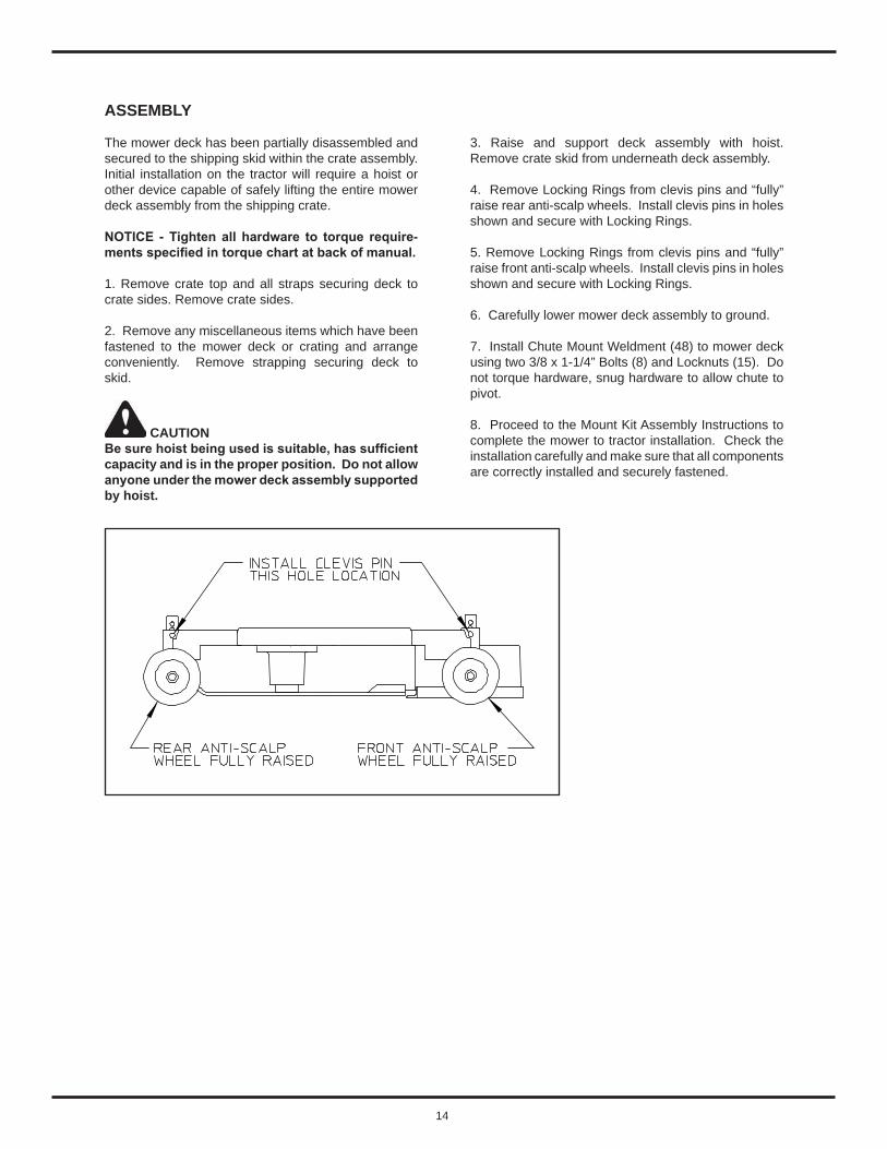
4. Remove Locking Rings from clevis pins and “fully” raise rear anti-scalp wheels. Install clevis pins in holes shown and secure with Locking Rings.
5. Remove Locking Rings from clevis pins and “fully” raise front anti-scalp wheels. Install clevis pins in holes shown and secure with Locking Rings.
6. Carefully lower mower deck assembly to ground.
7. Install Chute Mount Weldment (48) to mower deck using two 3/8 x 1-1/4” Bolts (8) and Locknuts (15). Do not torque hardware, snug hardware to allow chute to pivot.
8. Proceed to the Mount Kit Assembly Instructions to complete the mower to tractor installation. Check the installation carefully and make sure that all components are correctly installed and securely fastened.
15
NOTE – If there is access to an overhead hoist with the proper lift rating, the operator has the option of installing the deck to the tractor by raising the front of the tractor and rolling the mower deck rearward, under the tractor.
NOTE - The most common method for installation is to drive the tractor over the mower deck. Remove loader and backhoe if installed prior to installing deck.
Begin the process by selecting and placing wood “blocking” which will act as a “ramp” at the back and front of the mower.
Start tractor and place tractor in the lowest 4WD gear possible. Carefully drive forward and align front wheels with “ramp” created earlier. Proceed forward and continue until deck is located between front and rear wheels of tractor.
Shut off engine and remove key. Remove blocking material from front and back of deck.
SEE DIAGRAM NEXT PAGE
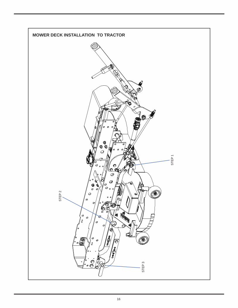
Step 1. Secure Right and Left Hand Link Assemblies to back of deck. Use Clevis Pins and Lynch Pins.
NOTICE: Lynch Pin must be assembled to outside of deck as shown. Failure to assemble the Lynch Pin in the correct manner will lead to Clevis Pin falling out in due course of time. This may lead to severe damage to mower and tractor and impact warranty.
Step 2. Install rod portion of Lower Mount Link Weldment to hook area at front of mower deck.
Step 3. At front of tractor, pull out spring loaded J-Pin located on left hand side of tractor. Raise Lower Mount Link Assembly into hooks on Latch Weldment. Be careful not to pinch fingers or hand and rotate handle of Latch Weldment upward to secure assembly into Front Mount Plates. Release J-Pin into hole on Front Mount Plates and through hole in Latch Weldment.
NOTE: For optimum cutting, it is recommended to leave the base loader and backhoe off the tractor. Leaving the base loader and backhoe off the tractor will reduce ground compaction by the tires, improve overall maneuverability and improve the view of the cutting area from the operator’s seat.
MOWER DECK INSTALLATION TO TRACTOR
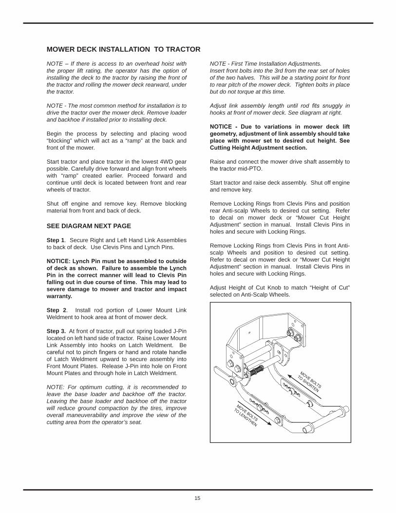
NOTE - First Time Installation Adjustments.Insert front bolts into the 3rd from the rear set of holes of the two halves. This will be a starting point for front to rear pitch of the mower deck. Tighten bolts in place but do not torque at this time.
Adjust link assembly length until rod fits snuggly in hooks at front of mower deck. See diagram at right.
NOTICE - Due to variations in mower deck lift geometry, adjustment of link assembly should take place with mower set to desired cut height. See Cutting Height Adjustment section.
Raise and connect the mower drive shaft assembly to the tractor mid-PTO.
Start tractor and raise deck assembly. Shut off engine and remove key.
Remove Locking Rings from Clevis Pins and position rear Anti-scalp Wheels to desired cut setting. Refer to decal on mower deck or “Mower Cut Height Adjustment” section in manual. Install Clevis Pins in holes and secure with Locking Rings.
Remove Locking Rings from Clevis Pins in front Anti-scalp Wheels and position to desired cut setting. Refer to decal on mower deck or “Mower Cut Height Adjustment” section in manual. Install Clevis Pins in holes and secure with Locking Rings.
Adjust Height of Cut Knob to match “Height of Cut” selected on Anti-Scalp Wheels.
MOVE BOLTS
TO SHORTEN
MOVE BOLTS
TO LENGTHEN
16
MOWER DECK INSTALLATION TO TRACTOR
STE
P 2
STE
P 3
STE
P 1

17
Park the unit on a smooth hard surface. Raise deck. Stop the engine. Set parking brake and remove key.
Remove Locking Rings from Clevis Pins and “fully” raise rear Anti-scalp Wheels. Install Clevis Pins in holes shown and secure with Locking Rings.
Remove Locking Rings from Clevis Pins and “fully” raise front Anti-scalp Wheels. Install Clevis Pins in holes shown and secure with Locking Rings.
Adjust Height of Cut Knob to Install position. This will allow lift system to completely lower.
Lower the mower deck to the ground using the three point hitch lever.
Disconnect the mower drive shaft assembly from the tractor mid-PTO. Lower the drive shaft so it rests on ground.
Remove Clevis Pins and Lynch Pins from the Right and Left Hand Link Assemblies at back of deck. Reinstall Clevis Pins and Lynch Pins.
At front of tractor, pull out spring loaded J-Pin located on left hand side of tractor. Rotate handle weldment downward to release assembly from Front Mount Plates.
MOWER DECK REMOVAL FROM TRACTOR
Remove link assembly from hook area at front of mower deck.
NOTE – If there is access to an overhead hoist with the proper lift rating, the operator has the option of removing the deck from under the tractor by raising the front of the tractor and rolling the mower deck forward, from under the tractor.
NOTE - The most common method for removal is to drive the tractor over the mower deck. Make sure loader and backhoe is removed from tractor if installed.
Begin the process by selecting and placing wood “blocking” which will act as a “ramp” at the back and front of the mower.
Start tractor and place tractor in the lowest 4WD reverse gear possible. Carefully back up while aligning front wheels with “ramp” created earlier. Proceed rearward and continue until deck is located at front of tractor.
Shut off engine and remove key. Remove blocking material from front and back of deck.
18
LUBRICATION
NOTICE: It is not recommended to use a pressure washer to clean the mower assembly. High pressure water may cause damage to spindles, pulleys, belts, or bearings shortening life and reducing serviceability.
Life of the mower depends upon the maintenance given. Proper lubrication is very important. Always lubricate the deck and lift components before operation.
Always wipe the fittings to be lubricated with a clean cloth before greasing. Dirt injected into the fitting will cause damage to the machined parts.
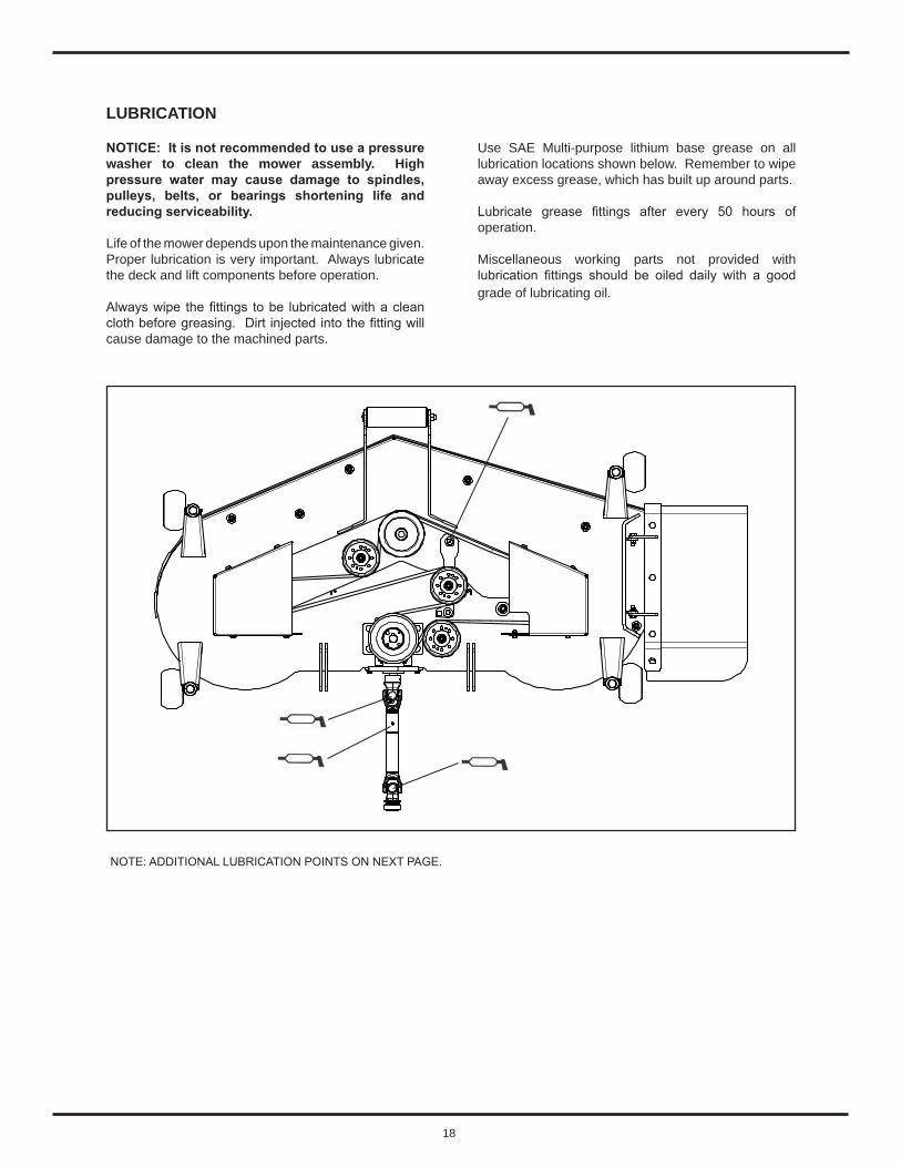
Use SAE Multi-purpose lithium base grease on all lubrication locations shown below. Remember to wipe away excess grease, which has built up around parts.
Lubricate grease fittings after every 50 hours of operation.
Miscellaneous working parts not provided with lubrication fittings should be oiled daily with a good grade of lubricating oil.
NOTE: ADDITIONAL LUBRICATION POINTS ON NEXT PAGE.

19
LUBRICATION CONTINUED
RH LOWERDRAFT ARM AREA
LH LOWERDRAFT ARM AREA
REAR MOUNTASSEMBLY AREA

20
CUTTING HEIGHT ADJUSTMENT
NOTICE: The Mower is to be operated with the front anti-scalp wheels and rear anti-scalp wheels above the ground.
The anti-scalp height is set by positioning the right and left wheels in one of three index hole settings. The hole settings range in 1/2” increments from a cutting height of approximately 2 inch (bottom hole) to 4 inches (top hole).
INITIAL SET UPTo initially adjust the deck, park on level ground and set the Height of Cut Knob to the 4 inch height of cut. Lower the 3 point arms. Have each of the anti-scalp wheels placed in the middle hole position. Place a 2 x 4 horizontally under each of the anti-scalp wheels. Tighten or loosen the nuts on the Lift Rods until you can slide the 2 x 4 under the wheel with wheel slightly touching.
After selecting the height of cut, the anti-scalp wheels are adjusted as follows.
Start the tractor and raise the mower deck to the upmost position by raising the three point hitch lever. Set parking brake, shut off engine and remove key.
WARNING – Use caution when adjusting deck cutting height. Block mower deck before proceeding with adjustment. The mower deck’s weight is supported by the tractor lift system. The deck could drop if the three point lift lever is accidentally shifted.
After determining the desired cut height as shown in the chart, and on the mower deck itself, adjust each anti-scalp wheel.
Remove Locking Ring and Clevis Pin from deck bushing. Align the hole in the wheel spindle with the hole in the deck bushing and install Clevis Pin. Secure with Locking Ring.
Repeat process for other three anti-scalp wheel spindles.
NOTE - Make sure the corresponding height hole setting is used in all four anti-scalp wheel settings.
Adjust the Height of Cut Knob to the corresponding desired cut height position.
HEIGHT OF CUT KNOB
NOTICE: To set Cut of Height, raise Knob and Collar Assembly until Spring Pin under Collar disengages from Height of Cut Plate. Rotate Knob and Collar Assembly until arrow on Knob label points to selected Operation or Cut of Height dimension on Height of Cut Plate. Make sure Spring Pin in Knob and Collar Assembly engages in slot located in Height of Cut Plate.
COLLAR
“SLOTS” IN CUT OF HEIGHT PLATE
21
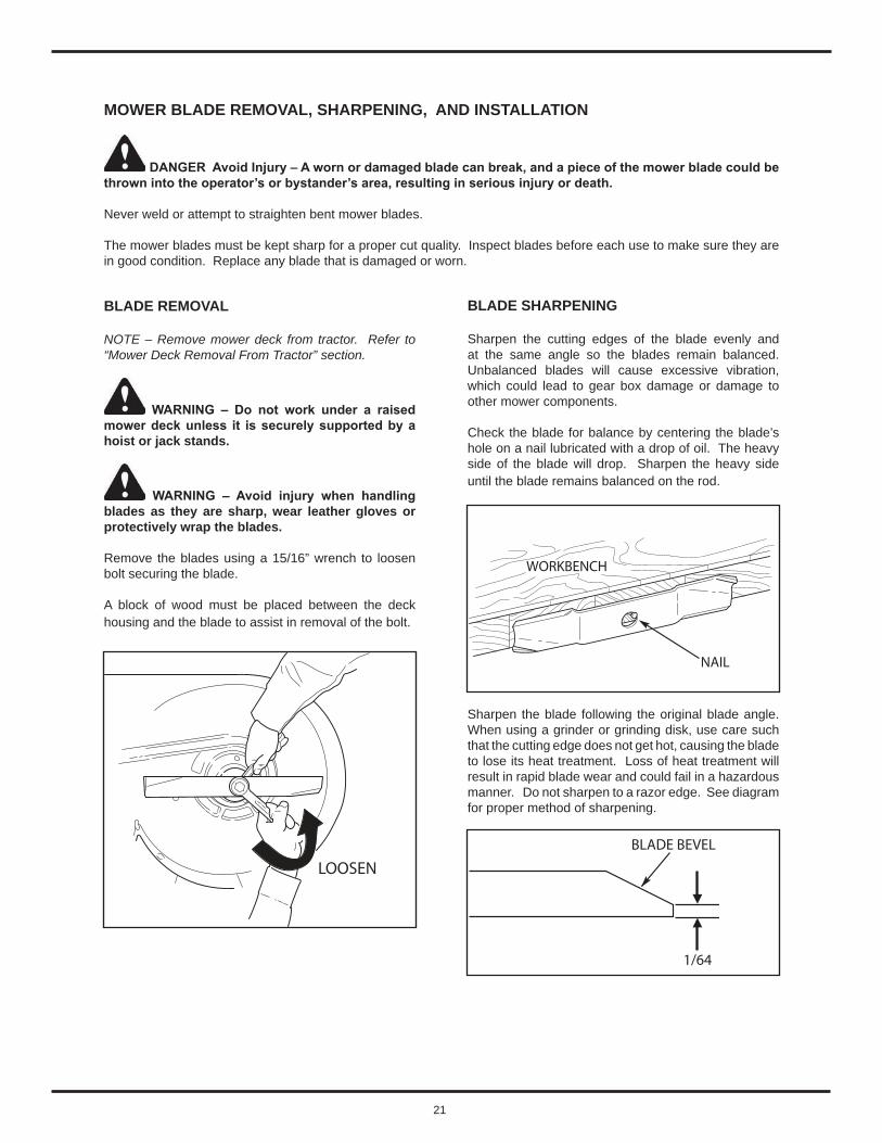
BLADE REMOVAL
NOTE – Remove mower deck from tractor. Refer to “Mower Deck Removal From Tractor” section.
WARNING – Do not work under a raised mower deck unless it is securely supported by a hoist or jack stands.
WARNING – Avoid injury when handling blades as they are sharp, wear leather gloves or protectively wrap the blades.
Remove the blades using a 15/16” wrench to loosen bolt securing the blade.
A block of wood must be placed between the deck housing and the blade to assist in removal of the bolt.
MOWER BLADE REMOVAL, SHARPENING, AND INSTALLATION
BLADE SHARPENING Sharpen the cutting edges of the blade evenly and at the same angle so the blades remain balanced. Unbalanced blades will cause excessive vibration, which could lead to gear box damage or damage to other mower components.
Check the blade for balance by centering the blade’s hole on a nail lubricated with a drop of oil. The heavy side of the blade will drop. Sharpen the heavy side until the blade remains balanced on the rod.
Sharpen the blade following the original blade angle. When using a grinder or grinding disk, use care such that the cutting edge does not get hot, causing the blade to lose its heat treatment. Loss of heat treatment will result in rapid blade wear and could fail in a hazardous manner. Do not sharpen to a razor edge. See diagram for proper method of sharpening.
DANGER Avoid Injury – A worn or damaged blade can break, and a piece of the mower blade could be thrown into the operator’s or bystander’s area, resulting in serious injury or death.
Never weld or attempt to straighten bent mower blades.
The mower blades must be kept sharp for a proper cut quality. Inspect blades before each use to make sure they are in good condition. Replace any blade that is damaged or worn.
LOOSEN
NAIL
WORKBENCH
BLADE BEVEL
1/64

22
If the cutting edge of the blade has had more than a 1/2” of the metal removed from sharpening or wear, the blade must be replaced.
If the “air lift” area of the blade has eroded and a notch has developed and is 1/4” deep or greater, the blade must be replaced.
BLADE INSTALLATION
When reinstalling the blade note orientation, the “wing” must be pointing upward toward the top of the deck. Torque the bolt to 204 ft-lbs.
Check and re-torque the blade retaining bolt after the first hour of mower operation.
1/2”
NEW BLADE
BEVEL
BEVEL
WORNBLADE
“AIR LIFT”
NEW BLADE
1/4”
WORN BLADE
TIGHTEN

23
REMOVAL
Remove hardware securing the Right Hand Belt cover to the deck.
Remove hardware securing the Left Hand Belt cover to the deck.
Note the routing of the belt to help ensure proper installation of the new belt. Refer to belt diagram decal on deck.
CAUTION – The Idler Arm with Idler Pulley are under spring tension. To prevent possible injury, use caution when handling the Idler Arm assembly.
Place a “Breaker Bar” in the square hole provided in the Idler Arm. Carefully push the Idler Arm towards the left hand side, away from discharge opening to relieve tension from the belt. Slip the belt off of the Right Hand Spindle Pulley, then carefully release the Idler Arm.
Remove the belt from the Center Spindle Pulley.
Remove the belt from the first fixed Idler Pulley.
Remove the belt from the Left Hand Spindle Pulley.
Remove the belt from the Idler Arm Pulley.
Remove the belt from the Gear Box Pulley.
Remove the belt from the second Idler Pulley.
Remove the belt from the deck and discard.
INSTALLATION
Route the “backside” of the belt around the fixed Idler Pulley near Gear Box.
Route belt around Gear Box Pulley.
Route the belt around the Idler Arm Pulley. The “backside” of the belt will be making contact with the Idler Arm Pulley.
Route belt around the Left Hand Spindle Pulley.
Route the “backside” of the belt around the fixed Idler Pulley near Center Spindle.
Route belt around the Center Spindle Pulley.
Make certain the belt is properly engaged in each pulley, then place a “Breaker Bar” in the square hole provided in the Idler Arm. Carefully push the Idler Arm towards the left hand side, away from discharge opening to relieve tension. Slip the belt over the Right Hand Spindle Pulley, then carefully release the Idler Arm.
Reinstall Right Hand and Left Hand Belt covers to the deck.
BELT REPLACEMENT
The mower deck belts should be replaced every 200 hours of mower operation, or anytime the belts shows signs of wear, cracking, or other damage.
NOTICE – The mower MUST be removed from the tractor for belt replacement. See “Mower Deck Removal” section for proper procedure.
24
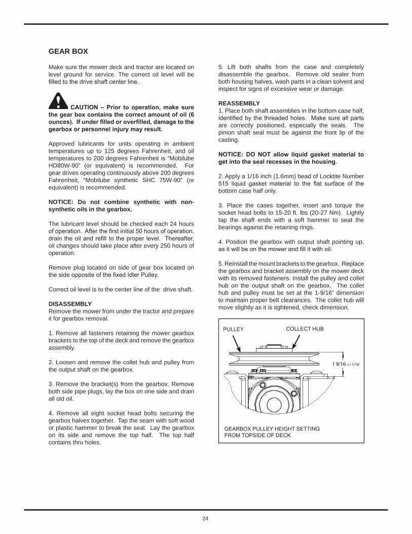
GEAR BOX
Make sure the mower deck and tractor are located on level ground for service. The correct oil level will be filled to the drive shaft center line.
CAUTION – Prior to operation, make sure the gear box contains the correct amount of oil (6 ounces). If under filled or overfilled, damage to the gearbox or personnel injury may result.
Approved lubricants for units operating in ambient temperatures up to 125 degrees Fahrenheit, and oil temperatures to 200 degrees Fahrenheit is “Mobilube HD80W-90” (or equivalent) is recommended. For gear drives operating continuously above 200 degrees Fahrenheit, “Mobilube synthetic SHC 75W-90” (or equivalent) is recommended.
NOTICE: Do not combine synthetic with non-synthetic oils in the gearbox.
The lubricant level should be checked each 24 hours of operation. After the first initial 50 hours of operation, drain the oil and refill to the proper level. Thereafter, oil changes should take place after every 250 hours of operation.
Remove plug located on side of gear box located on the side opposite of the fixed Idler Pulley.
Correct oil level is to the center line of the drive shaft.
DISASSEMBLYRemove the mower from under the tractor and prepare it for gearbox removal.
1. Remove all fasteners retaining the mower gearbox brackets to the top of the deck and remove the gearbox assembly.
2. Loosen and remove the collet hub and pulley from the output shaft on the gearbox.
3. Remove the bracket(s) from the gearbox. Remove both side pipe plugs, lay the box on one side and drain all old oil.
4. Remove all eight socket head bolts securing the gearbox halves together. Tap the seam with soft wood or plastic hammer to break the seal. Lay the gearbox on its side and remove the top half. The top half contains thru holes.
5. Lift both shafts from the case and completely disassemble the gearbox. Remove old sealer from both housing halves, wash parts in a clean solvent and inspect for signs of excessive wear or damage.
REASSEMBLY1. Place both shaft assemblies in the bottom case half, identified by the threaded holes. Make sure all parts are correctly positioned, especially the seals. The pinion shaft seal must be against the front lip of the casting.
NOTICE: DO NOT allow liquid gasket material to get into the seal recesses in the housing.
2. Apply a 1/16 inch (1.6mm) bead of Locktite Number 515 liquid gasket material to the flat surface of the bottom case half only.
3. Place the cases together, insert and torque the socket head bolts to 15-20 ft. lbs (20-27 Nm). Lightly tap the shaft ends with a soft hammer to seat the bearings against the retaining rings.
4. Position the gearbox with output shaft pointing up, as it will be on the mower and fill it with oil.
5. Reinstall the mount brackets to the gearbox. Replace the gearbox and bracket assembly on the mower deck with its removed fasteners. Install the pulley and collet hub on the output shaft on the gearbox. The collet hub and pulley must be set at the 1-9/16” dimension to maintain proper belt clearances. The collet hub will move slightly as it is tightened, check dimension.
1 9/16 +/-1/16
GEARBOX PULLEY HEIGHT SETTING FROM TOPSIDE OF DECK
PULLEY COLLECT HUB
25
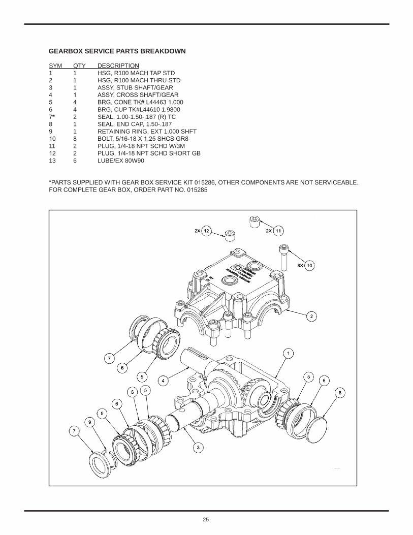
GEARBOX SERVICE PARTS BREAKDOWN
SYM QTY DESCRIPTION1 1 HSG, R100 MACH TAP STD 2 1 HSG, R100 MACH THRU STD3 1 ASSY, STUB SHAFT/GEAR4 1 ASSY, CROSS SHAFT/GEAR5 4 BRG, CONE TK# L44463 1.0006 4 BRG, CUP TK#L44610 1.98007* 2 SEAL, 1.00-1.50-.187 (R) TC8 1 SEAL, END CAP, 1.50-.1879 1 RETAINING RING, EXT 1.000 SHFT10 8 BOLT, 5/16-18 X 1.25 SHCS GR811 2 PLUG, 1/4-18 NPT SCHD W/3M12 2 PLUG, 1/4-18 NPT SCHD SHORT GB13 6 LUBE/EX 80W90
*PARTS SUPPLIED WITH GEAR BOX SERVICE KIT 015286, OTHER COMPONENTS ARE NOT SERVICEABLE.FOR COMPLETE GEAR BOX, ORDER PART NO. 015285

26
COMMON MOWING PROBLEMS
STREAKING
Streaking is when thin strips of uncut grass are left behind the mower. Streaking is usually caused by operator error or poor blade maintenance.
CAUSE SOLUTIONBlades are not sharp. Sharpen your blades.Blades are worn down too far. Replace your blades.Engine speed is too slow. Always mow at rated PTO engine speed.Ground speed is too fast. Slow down.Deck is plugged with grass. Clean out the mower.Not overlapping cutting rows enough. Overlap your cutting rows.Not overlapping enough when turning. When turning your effective cutting width decreases
- overlap more when turning.
STINGERS
Stingers are sparse patches of uncut grass left behind the mower. Stingers are usually caused by operator error or poor blade maintenance.
CAUSE SOLUTIONBlades are not sharp or are nicked. Sharpen your blades.Blades are worn down too far. Replace your blades.Engine speed is too slow. Always mow at rated PTO engine speed.Ground speed is too fast. Slow down.Deck is plugged with grass. Clean out the mower.

27
UNEVEN CUTTING
Uneven cutting is waviness or smooth troughs in the law surface. Uneven cutting is usually caused by mower deck damage or mis-adjustment..
CAUSE SOLUTIONDeck is not leveled correctly. Level the deck correctly.Blades are dull or worn. Sharpen or replace the blades.Blades are damaged. Replace the blades.Deck is clogged with grass clippings. Clean out the deck.Deck shell is damaged. Repair or replace the deck.Mower spindle is bent or loose. Repair or replace the spindle.Blades are installed incorrectly. Reinstall the blades correctly.
SCALPING
Scalping is when the mower deck comes close to or hits the ground. Scalping can be caused by the mower deck misadjustment, unevenness in the lawn, or by mower deck bouncing because the ground speed is too fast.
CAUSE SOLUTIONLawn is uneven or bumpy. Roll or level the lawn.Mower deck cutting height is set too low. Raise the cutting height.Ground speed is too fast. Slow down.Deck is not leveled correctly. Correctly level the deck.Tire pressure is low or uneven. Check and inflate the tires.
COMMON MOWING PROBLEMS

28
STEPPED CUTTING
Stepped cutting is sharp ridges or uneven levels left in the lawn surface. Stepped cutting is usually caused by mower deck damage or mis-adjustment, or damage to mower blades.
CAUSE SOLUTIONDeck is not leveled correctly. Level the deck correctly.Tires are not properly inflated. Check and inflate the tires.Blades are damaged. Replace the blades.Deck shell is damaged. Repair or replace the deck.Mower spindle is bend or loose. Repair or replace the spindle.Blades are installed incorrectly. Reinstall the blades correctly.
COMMON MOWING PROBLEMS

29
PROBLEM
Mower will not raise.
Mower cut is uneven.
Mower cut is rough looking.
Engine stalls easily with mower engaged.
Excessive mower vibration.
Excessive belt wear or breakage.
Mower drive belt slips or fails to drive.
CAUSE
• Lift linkage not properly attached or damaged.
• Dirt in hydraulic lines.
• Mower not leveled properly.• Tractor tires not inflated equally
or properly.• Cutting with attachment lift in
raised position.
• Engine speed too slow.• Ground speed too fast.• Blades are dull.
• Mower drive belt slipping because it is oily or worn.
• Blades not properly fastened to arbors.
• Engine speed too slow.• Ground speed too fast.• Mower choked with grass.• Cutting height set too low.
• Discharge chute jamming with cut grass.
• Engine not up to operating temperature.
• Starting mower in tall grass.
• Blade mounting bolts are loose.
• Mower blades, arbors, or pulleys are bent.
• Mower blades are out of balance.
• Mower choked with grass.
• Bent or rough pulleys.• Using incorrect belt.• Excessive debris under cover.
• Idler pulley spring broken or not properly attached.
• Excessive debris under covers.• Mower drive belt broken.
CORRECTION
Attach or repair.
Change hydraulic system filter.
See Mower Adjustment.See Tractor Manual Maintenance Section.Lower attachment lift.
Set to full throttle.Slow down.Sharpen or replace blades. See Mower Blade Service Section.Clean or replace belt as necessary.
See Mower Blade Service Section.
Set to full throttle.Slow down.Clean out mower deck.Cut tall grass at maximum cutting height during first pass.Cut grass with discharge pointing toward previously cut area.Run engine for several minutes to warm-up.Start the mower in a cleared area.
Tighten 204 ft. lbs.
Check and replace as necessary.
Remove, sharpen, and balance blades. See Mower Blade Service Section.Clean out mower deck.
Repair or replace.Replace with correct belt.Remove covers and clean out mower deck.
Repair or replace as needed.
Clean out mower deck.Replace drive belt.
TROUBLESHOOTING THE MOWER

30
MOWER DECK SERVICE PARTS BREAKDOWN
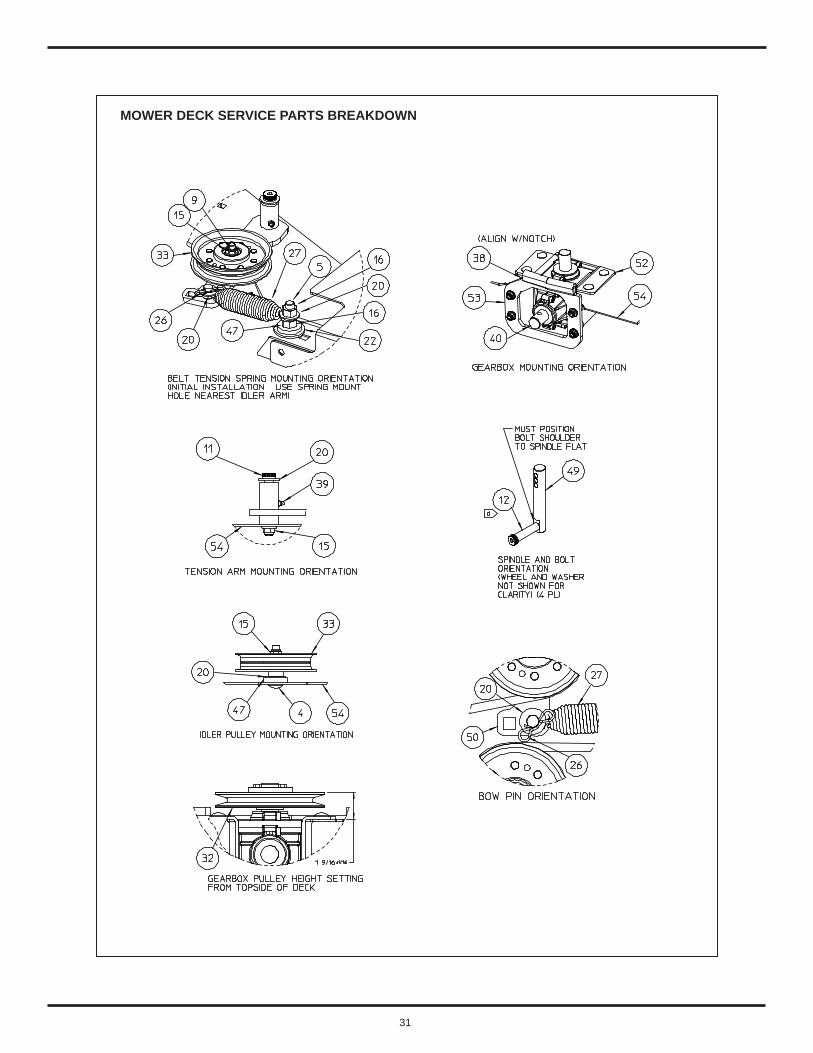
31
MOWER DECK SERVICE PARTS BREAKDOWN

32
MOWER DECK SERVICE PARTS BREAKDOWN
SYM QTY PART DESCRIPTION1 6 006606 Carriage Bolt, 3/8-16 x .75 2 8 006608 Carriage Bolt, 3/8-16 x 1.03 12 006616 Carriage Bolt, 3/8-16 x 1.50 Gr 5 SAE4 2 006618 Carriage Bolt, 3/8-16 x 2.25 Gr 55 1 006672 Carriage Bolt, 1/2-13 x 2.06 1 006680 Carriage Bolt, 1/2-13 x 97 12 006787 Hex Head Capscrew, 5/16-18 x .75 Gr 58 6 006855 Hex Head Capscrew, 3/8-16 x 1-1/49 1 006872 Hex Head Capscrew, 3/8-16 x 2.00 Gr 510 3 007017 Hex Head Capscrew, 1/2-20 x 1.2511 1 007052 Shoulder Bolt, Hex 3/8-16 x .5 x 2.512 4 007057 Shoulder Bolt, Hex 1/2-13 x .625 x 2.7513 3 007130 Hex Head Capscrew, 5/8-18 x 1.50 Gr 514 8 007432 Spring Nut, 5/16-1815 36 007457 Nut, Hex Flange 3/8-16 GF Lock Nylon16 3 007508 Nut, Hex 1/2-13 Gr 5 Lock17 8 008151 Flat Washer, 5/1618 4 008152 Flat Washer, 5/16 SAE 19 1 008158 Flat Washer, 3/8 SAE20 12 008173 Flat Washer, 1/2 SAE21 3 008178 Flat Washer, 5/8 Hardened SAE22 1 008180 Flat Washer, 5/8 .687 x 1.75 x .11523 8 008183 Flat Washer, 5/8 SAE24 3 008197 Flat Washer, 7/8 .938 x 1.75 x .134 SAE25 4 008547 Locking Ring26 1 008548 Clip, Bow Tie Pin27 1 008751 Spring, Swivel End28 1 008920 Key, 1/4 x 1.029 3 008921 Key, 3/16 square30 3 011921 Dust Cover31 1 012749 Bushing, Mower Gear Box 32 1 012752 Pulley, Gearbox33 3 012756 Pulley, Idler 4”34 3 012760 Pulley, Spindle35 1 012763 V-Belt36 4 012969 Wheel37 4 013459 Clevis Pin38 1 014212 Stop, Rubber Lip39 1 014505 Grease Fitting, Straight 1/4-2840 1 015285 Gearbox41 1 050005 Chute, Discharge Rubber42 3 050008 Blade, Mower 21”43 3 050012 Spindle Assembly44 1 066167 Anti-Scalp Roller45 1 451186 Chute Retainer Plate46 1 451470 LH Belt Guard Plate with Decal47 5 451709 Pulley Spacer Plate48 1 451760 Chute Mount Weldment49 4 451764 Spindle, Wheel (Threaded)50 1 451800 Idler Arm Weldment51 1 451890 RH Belt Guard Plate with Decal52 2 451804 Gear Box Mount Plate53 1 451853 Rear Upstop Plate54 1 451770 60” Deck Weldment with Decals

33
SPECIFICATIONS - 60” MOWER DECK
Tractor Required Mahindra EMAX 22/25
Cutting Width 60 inches
Overall Width 74 inches
Cutting Height Range 2 to 4 inches
Deck Shell Thickness 10 Gauge (.1345 inches) Grade 50 Steel
Spindle Speed at 2800 RPM 3150 RPM
Blade Tip Speed 17,350 Feet per Minute
Number of Blades 3
Blade Length 21 inches
Blade Width 2-1/2 inches
Blade Thickness 1/4 inches
Shipping Weight of Base 60” Deck and Mounting 411 pounds Specifications may vary depending on tractor model and are subject to change without notification.
Tractors must be equipped with a Rollover Protective System (ROPS) and seat belt that will provide better safety.

34
GENERAL DESCRIPTION
Tractor will require setup, please consult your tractor Operator’s Manual for important safety precautions.
NOTICE: Tractor will require the installation of mid-PTO Kit if one has not already been installed from the factory, before installation of mower deck.
TRACTORS WITH LOADER
NOTICE: Remove Loader from tractor prior to installation of this kit. Refer to your Loader Operator’s Manual for proper removal procedure. Some loader mounting components attached to tractor will be removed and discarded.
NOTICE: Tighten all hardware to the torque require-ments specified in the installation instructions or torque chart.
The terms RIGHT, LEFT, FORWARD and REAR are determined when in the correct operating position on the tractor seat.
NOTICE: For ease of assembly do not tighten any hardware until specified in the following instructions.
PTO DRIVE SHAFT INSTALLATION
1. Install the PTO Drive Shaft (37) onto the mower deck gearbox input shaft. See Mount Kit parts breakdown, page 42.
2. Secure PTO Drive Shaft (37) to the gearbox input shaft using a Retaining Ring (28), and Internal Socket Head 5/16 NC x 1-3/4” Bolt (2) with Locknut (3). The Lock Nut must NOT be torqued. The Lock Nut should only be tightened until “snug” against the PTO Drive Shaft Yoke. Do not over tighten.
NOTICE: The Retaining Ring MUST be installed onto the gear box input shaft. Failure to install Retaining Ring will allow the PTO Drive Shaft to come off in the event the Shear Bolt breaks. Severe damage to mower and tractor components will result.
NOTICE: Should the two halves of the PTO Drive Shaft separate, please note the following reassembly process.
There is a blind spline between the drive shaft halves. The blind portion on the female spline on the tractor half, is located 180 degrees (opposite side) from the grease fitting. This portion should be matched up with the male spline on the mower half of the drive shaft.
Use a SAE multipurpose grease to lubricate all three fittings.
MAHINDRA 60” MOWER MOUNT KIT INSTRUCTIONSFOR EMAX 22 AND EMAX 25 TRACTORS
35
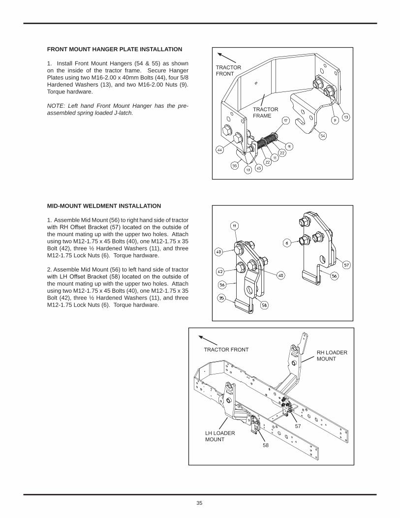
FRONT MOUNT HANGER PLATE INSTALLATION
1. Install Front Mount Hangers (54 & 55) as shown on the inside of the tractor frame. Secure Hanger Plates using two M16-2.00 x 40mm Bolts (44), four 5/8 Hardened Washers (13), and two M16-2.00 Nuts (9). Torque hardware.
NOTE: Left hand Front Mount Hanger has the pre-assembled spring loaded J-latch.
MID-MOUNT WELDMENT INSTALLATION
1. Assemble Mid Mount (56) to right hand side of tractor with RH Offset Bracket (57) located on the outside of the mount mating up with the upper two holes. Attach using two M12-1.75 x 45 Bolts (40), one M12-1.75 x 35 Bolt (42), three ½ Hardened Washers (11), and three M12-1.75 Lock Nuts (6). Torque hardware.
2. Assemble Mid Mount (56) to left hand side of tractor with LH Offset Bracket (58) located on the outside of the mount mating up with the upper two holes. Attach using two M12-1.75 x 45 Bolts (40), one M12-1.75 x 35 Bolt (42), three ½ Hardened Washers (11), and three M12-1.75 Lock Nuts (6). Torque hardware.
TRACTOR FRONT RH LOADERMOUNT
LH LOADERMOUNT
58
57
TRACTOR FRONT
TRACTOR FRAME
36
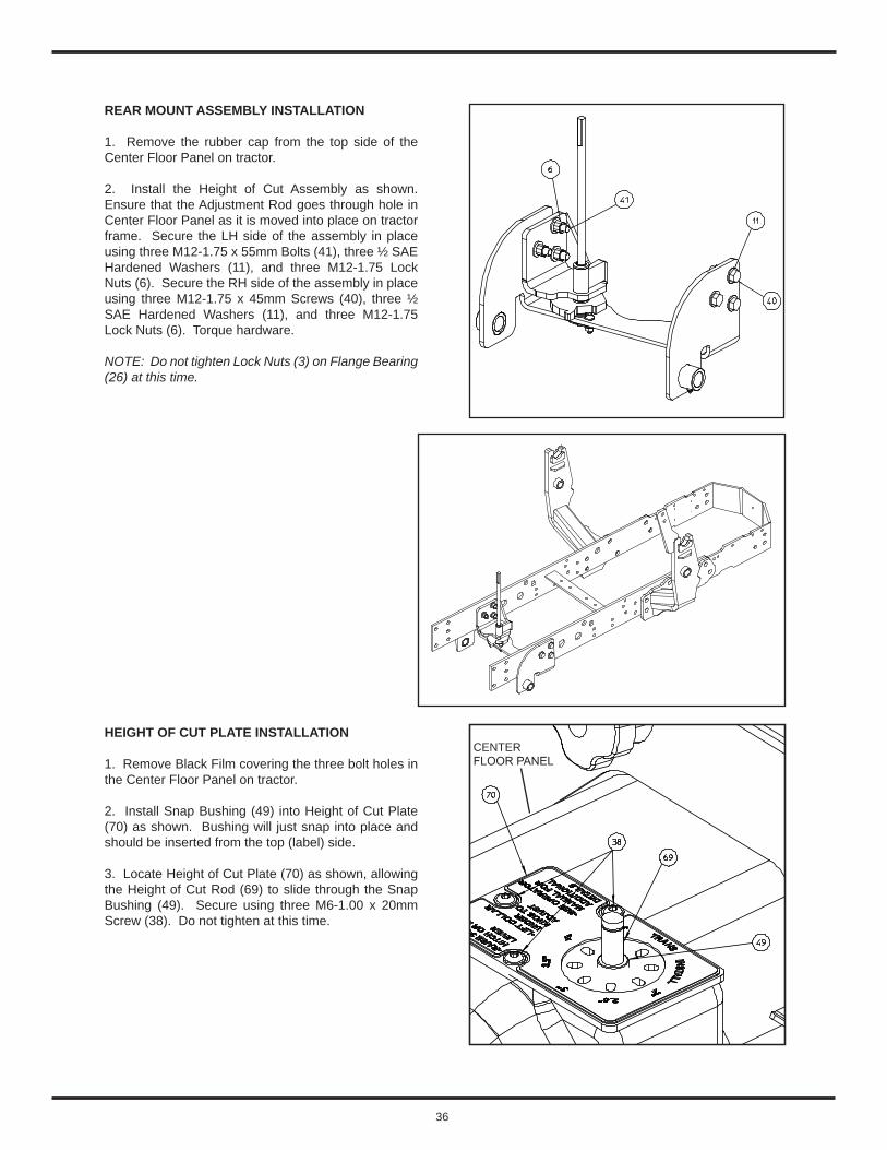
REAR MOUNT ASSEMBLY INSTALLATION
1. Remove the rubber cap from the top side of the Center Floor Panel on tractor.
2. Install the Height of Cut Assembly as shown. Ensure that the Adjustment Rod goes through hole in Center Floor Panel as it is moved into place on tractor frame. Secure the LH side of the assembly in place using three M12-1.75 x 55mm Bolts (41), three ½ SAE Hardened Washers (11), and three M12-1.75 Lock Nuts (6). Secure the RH side of the assembly in place using three M12-1.75 x 45mm Screws (40), three ½ SAE Hardened Washers (11), and three M12-1.75 Lock Nuts (6). Torque hardware.
NOTE: Do not tighten Lock Nuts (3) on Flange Bearing (26) at this time.
HEIGHT OF CUT PLATE INSTALLATION
1. Remove Black Film covering the three bolt holes in the Center Floor Panel on tractor.
2. Install Snap Bushing (49) into Height of Cut Plate (70) as shown. Bushing will just snap into place and should be inserted from the top (label) side.
3. Locate Height of Cut Plate (70) as shown, allowing the Height of Cut Rod (69) to slide through the Snap Bushing (49). Secure using three M6-1.00 x 20mm Screw (38). Do not tighten at this time.
CENTERFLOOR PANEL
37
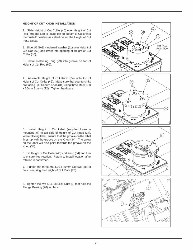
HEIGHT OF CUT KNOB INSTALLATION
1. Slide Height of Cut Collar (46) over Height of Cut Rod (69) and turn to locate pin on bottom of Collar into the “Install” position as called out on the Height of Cut Plate Decal.
2. Slide 1/2 SAE Hardened Washer (11) over Height of Cut Rod (69) and lower into opening of Height of Cut Collar (46).
3. Install Retaining Ring (29) into groove on top of Height of Cut Rod (69).
4. Assemble Height of Cut Knob (34) onto top of Height of Cut Collar (46). Make sure that countersinks are facing up. Secure Knob (34) using three M6 x 1.00 x 20mm Screws (72). Tighten hardware.
5. Install Height of Cut Label (supplied loose in mounting kit) to top side of Height of Cut Knob (34). While placing label, ensure that the groove on the label lines up with the groove on the Knob (34). The arrow on the label will also point towards the groove on the Knob (34).
6. Lift Height of Cut Collar (46) and Knob (34) and turn to ensure free rotation. Return to Install location after rotation is confirmed.
7. Tighten the three M6-1.00 x 20mm Screws (38) to finish securing the Height of Cut Plate (70).
8. Tighten the two 5/16-18 Lock Nuts (3) that hold the Flange Bearing (26) in place.
26
“INSTALL” POSITION
38
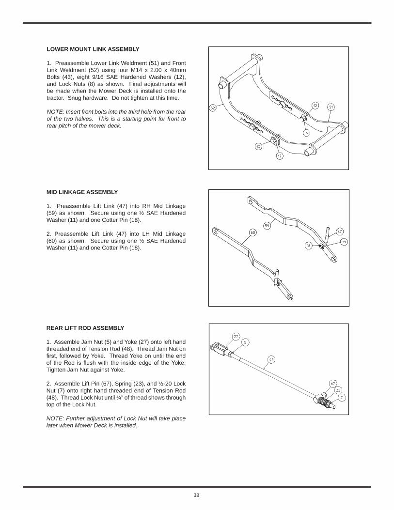
MID LINKAGE ASSEMBLY
1. Preassemble Lift Link (47) into RH Mid Linkage (59) as shown. Secure using one ½ SAE Hardened Washer (11) and one Cotter Pin (18).
2. Preassemble Lift Link (47) into LH Mid Linkage (60) as shown. Secure using one ½ SAE Hardened Washer (11) and one Cotter Pin (18).
REAR LIFT ROD ASSEMBLY
1. Assemble Jam Nut (5) and Yoke (27) onto left hand threaded end of Tension Rod (48). Thread Jam Nut on first, followed by Yoke. Thread Yoke on until the end of the Rod is flush with the inside edge of the Yoke. Tighten Jam Nut against Yoke.
2. Assemble Lift Pin (67), Spring (23), and ½-20 Lock Nut (7) onto right hand threaded end of Tension Rod (48). Thread Lock Nut until ¼” of thread shows through top of the Lock Nut.
NOTE: Further adjustment of Lock Nut will take place later when Mower Deck is installed.
LOWER MOUNT LINK ASSEMBLY
1. Preassemble Lower Link Weldment (51) and Front Link Weldment (52) using four M14 x 2.00 x 40mm Bolts (43), eight 9/16 SAE Hardened Washers (12), and Lock Nuts (8) as shown. Final adjustments will be made when the Mower Deck is installed onto the tractor. Snug hardware. Do not tighten at this time.
NOTE: Insert front bolts into the third hole from the rear of the two halves. This is a starting point for front to rear pitch of the mower deck.
39
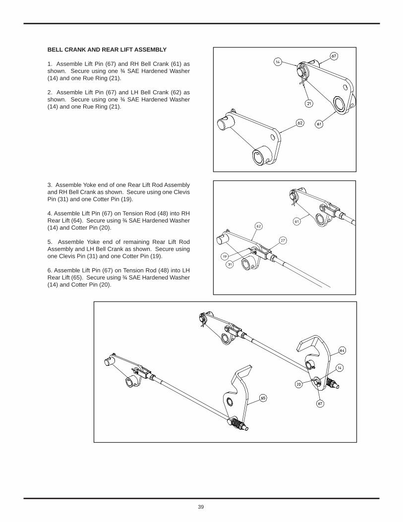
BELL CRANK AND REAR LIFT ASSEMBLY
1. Assemble Lift Pin (67) and RH Bell Crank (61) as shown. Secure using one ¾ SAE Hardened Washer (14) and one Rue Ring (21).
2. Assemble Lift Pin (67) and LH Bell Crank (62) as shown. Secure using one ¾ SAE Hardened Washer (14) and one Rue Ring (21).
3. Assemble Yoke end of one Rear Lift Rod Assembly and RH Bell Crank as shown. Secure using one Clevis Pin (31) and one Cotter Pin (19).
4. Assemble Lift Pin (67) on Tension Rod (48) into RH Rear Lift (64). Secure using ¾ SAE Hardened Washer (14) and Cotter Pin (20).
5. Assemble Yoke end of remaining Rear Lift Rod Assembly and LH Bell Crank as shown. Secure using one Clevis Pin (31) and one Cotter Pin (19).
6. Assemble Lift Pin (67) on Tension Rod (48) into LH Rear Lift (65). Secure using ¾ SAE Hardened Washer (14) and Cotter Pin (20).
40
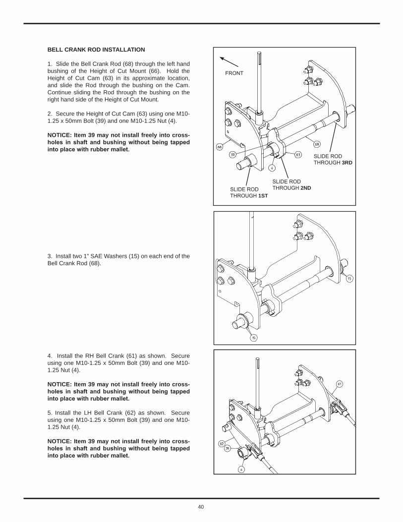
BELL CRANK ROD INSTALLATION
1. Slide the Bell Crank Rod (68) through the left hand bushing of the Height of Cut Mount (66). Hold the Height of Cut Cam (63) in its approximate location, and slide the Rod through the bushing on the Cam. Continue sliding the Rod through the bushing on the right hand side of the Height of Cut Mount.
2. Secure the Height of Cut Cam (63) using one M10-1.25 x 50mm Bolt (39) and one M10-1.25 Nut (4).
NOTICE: Item 39 may not install freely into cross-holes in shaft and bushing without being tapped into place with rubber mallet.
3. Install two 1” SAE Washers (15) on each end of the Bell Crank Rod (68).
4. Install the RH Bell Crank (61) as shown. Secure using one M10-1.25 x 50mm Bolt (39) and one M10-1.25 Nut (4).
NOTICE: Item 39 may not install freely into cross-holes in shaft and bushing without being tapped into place with rubber mallet.
5. Install the LH Bell Crank (62) as shown. Secure using one M10-1.25 x 50mm Bolt (39) and one M10-1.25 Nut (4).
NOTICE: Item 39 may not install freely into cross-holes in shaft and bushing without being tapped into place with rubber mallet.
SLIDE RODTHROUGH 1ST
SLIDE RODTHROUGH 2ND
SLIDE RODTHROUGH 3RD
FRONT

41
REAR LIFT INSTALLATION
1. Install the RH Rear Lift (64) by sliding the bushing over the Lower Link Pin on the Tractor. Secure using one Lynch Pin (32).
2. Install the LH Rear Lift (65) by sliding the bushing over the Lower Link Pin on the Tractor. Secure using one Lynch Pin (32).
MID LINKAGE INSTALLATION
1. Connect the Right and Left Hand Mid Linkages (59, 60) to the Right and Left Hand Mid Mounts (56, 57, 58) using ¾ Clevis Pins (30) and Lynch Pins (33).
2. Install the Lift Rods (47) already installed on the Right and Left Hand Mid Linkages (59, 60) into the Lift Pins (67) that are already installed on the Right and Left Hand Bell Cranks (61, 62). Secure by tightening a ½-20 Lock Nut (7) onto the Lift Rod (47) until ½” of thread shows through the top side of the Nut.
NOTE: Further Adjustment of Lock Nut will take place later when Mower Deck is leveled.

42
1. Park tractor on level ground.
2. Check tire pressures, make sure tire pressures are equal on right and left sides of same axle.
3. Adjust lift link to top hole for lower Right and Left Hand Lower Draft Arms.
5. Adjust the lock nuts evenly on each tension rod until the rear upstop on the mower deck comes into contact with the height of cut mount as shown.
6. Set the height of cut knob to the 4 inch cut height position by raising the collar under the knob and turning the dial until the arrow points towards the 4” call out. Lower the collar so that it seats itself in the notch on the height of cut plate.
7. Lower the 3-point hitch arms.
8. Place all four anti-scalp wheels in the middle hole position.
9. To check and adjust side to side levelness, place a 2 x 4 inch piece of wood horizontally under the rear anti-scalp wheels. Adjust the nuts on the lift rods until you can slide the 2 x 4 under the wheel with the wheel slightly touching. Tightening the lock nut on each side will raise that corresponding side.
10. To check front to rear pitch, rotate the left and right side mower blades until the blades are parallel (pointing front to back) with the tractor. Measure under the front and rear of the blade. The front measurement should be 1/8 inch lower than the rear.
11. To adjust front to rear pitch, support the front of the deck and unlatch front linkage from the front hanger brackets.
12. Loosen rear bolt (28) and move front bolt (28) to a different set of adjustment holes in both linkages as needed.
NOTE: Shortening the front linkage will raise the front of the deck and lengthening will lower the deck.
13. Re-latch the front linkage and check for proper mower deck pitch.
14. When the proper deck pitch is obtained, torque hardware.
UPPER HOLE
POINT OF CONTACT
HEIGHT OFCUT MOUNT
MOWER DECKUPSTOP
NOTICE: When deck is properly adjusted, the anti-scalp wheels should never ride on the ground. After height of cut (HOC) is selected, the four anti-scalp wheel heights should be set so that there is a 1/2” space between the bottom of the wheel and the ground. If the wheels ride continuously on the ground, rapid wheel wear will occur.
HANGERBRACKET
LATCH HANDLE
FRONT LINKAGE
MOWER DECK ADJUSTMENT - DECK LEVELNESS AND PITCH
LH LOWER DRAFT ARM
RH LOWERDRAFT ARM

43
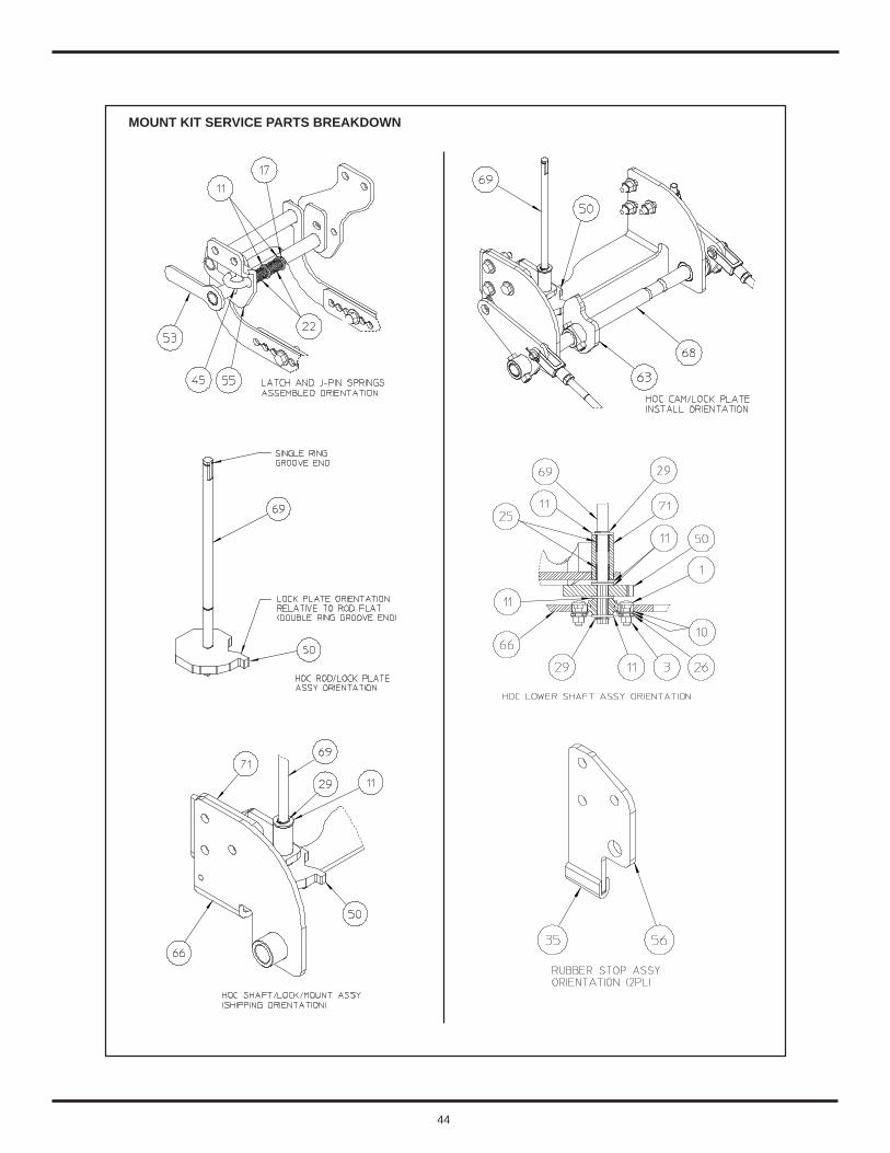
MOUNT KIT SERVICE PARTS BREAKDOWN
44
MOUNT KIT SERVICE PARTS BREAKDOWN

45
SYM QTY PART DESCRIPTION1 2 006577 Carriage Bolt, 5/16-18 x 1.0 Gr 52 1 006793 Socket Head Cap Screw, 5/16-18 x 1.753 3 007433 Lock Nut, Hex 5/16-18 Gr 54 3 007472 Nut, Hex M10-1255 2 007491 Nut, Hex 1/2-20 LH Gr 2 Jam6 12 007492 Lock Nut, Hex M12-1.75 Gr 10 FL7 4 007514 Nut, Flange 1/2-20 Lock Nylon8 4 007519 Nut, Hex M14-2.0 Gr 10 Lock Nylon9 4 007529 Nut, Hex M16-2.0010 6 008152 Flat Washer 5/16 SAE11 22 008164 Flat Washer 1/2 SAE Hardened12 8 008176 Flat Washer 9/16 SAE Hardened13 8 008178 Flat Washer 5/8 SAE Hardened14 4 008193 Flat Washer 3/4 Hardened15 4 008203 Flat Washer 1” SAE17 1 008554 Cotter Pin, 3/32 x 3/4 18 2 008557 Cotter Pin, 1/8 x 3/419 2 008560 Cotter Pin, 1/8 x 120 2 008574 Cotter Pin, 5/32 x 1-1/421 2 008640 Rue Ring22 2 008675 Compression Spring (Latch)23 2 008679 Lift Spring24 1 008959 Spring Pin, 3/16 x 3/425 2 011954 Bearing, Plain26 1 012271 Bearing, Flange27 2 012548 Yoke, Female (Straight)28 1 013237 Ring, Retaining29 3 013247 Ring, Retaining30 4 013358 Clevis Pin, 3/4 x 1-3/431 2 013463 Clevis Pin32 2 013484 Lynch Pin, .44 x 1.7533 4 013491 Lynch Pin, 1/4 Dia x 1.2534 1 453579 Plate, Height Of Cut Knob35 2 014214 Stop, Rubber Lip36 4 014505 Grease Fitting, Straight 1/4-2837 1 015583 PTO Drive Assembly
MOUNT KIT SERVICE PARTS BREAKDOWN

46
MOUNT KIT SERVICE PARTS BREAKDOWN
SYM QTY PART DESCRIPTION38 3 018508 Socket Head Cap Screw, M6-1 x 20 Gr 10.939 3 018619 Hex Head Cap Screw, M10-1.25 x 50 Gr 10.940 7 018654 Hex Head Cap Screw, M12-1.75 x 45 Gr 10.9 Fthd41 3 018657 Hex Head Cap Screw, M12-1.75 x 55 Gr 10.9 Fthd42 2 018658 Hex Head Cap Screw M12-1.75 x 35 Gr 10.943 4 018725 Hex Head Cap Screw M14-2.00 x 40 Gr 10.944 4 018757 Hex Head Cap Screw, M16-2.00 x 40 Gr 10.9 Fthd45 1 066073 J-Latch46 1 066199 Collar, Height Of Cut47 2 066187 Rod, Lift Link48 2 066188 Rod, Tension 22”49 1 066189 Bushing, Snap 1/2 ID50 1 066190 Plate, Height Of Cut51 1 453500 Lower Link Weldment52 1 453505 Front Link Weldment53 1 453510 Latch Weldment54 1 453516 RH Front Mount Hanger Plate55 1 453517 LH Front Mount Hanger Plate56 2 453518 Mid Mount Plate57 1 453521 RH Offset Plate58 1 453522 LH Offset Plate59 1 453523 RH Mid Linkage Plate60 1 453524 LH Mid Linkage Plate61 1 453535 RH Bell Crank Weldment62 1 453540 LH Bell Crank Weldment63 1 453545 Height Of Cut Cam Weldment64 1 453550 RH Rear Lift Weldment65 1 453555 LH Rear Lift Weldment66 1 453560 Height Of Cut Mount Weldment67 4 453571 Lift Pin68 1 453572 Bell Crank Rod69 1 453573 Height Of Cut Rod70 1 453574 Height Of Cut Plate71 1 453575 Height Of Cut Mount Weldment72 3 018509 Flat Head Hex Recess Screw, M6-1 x 20 Gr 10.9 DIN 7791

47
SERVICING THE PTO DRIVESHAFT ASSEMBLY
NOTE - Remove mower deck from tractor. Refer to Mower Deck Removal From Tractor section.
Remove the PTO drive shaft half that connects to the tractor mid PTO shaft and set it aside.
Disconnect second half of PTO Drive Shaft from the Gear Box input shaft and set it aside.
NOTICE - Access to a bench vise will ease service work. Make sure jaws in vise are protected such that no “metal on Metal” contact is made between jaws and drive shaft components.
TO DISASSEMBLE UNIVERSAL JOINT
1. Remove all external and internal snap rings.
2. Position joint in loose vice, strike top arm of unsupported yoke to drive the top cup up. Repeat on opposite side.
3. Grip loosened cup in vise, strike yoke arm to drive yoke off cup. Repeat on opposite cup.
4. Support cross in loose vise and stike yoke arm. Repeat Step 3 to remove remaining two cups.
5. Disconnect the rear half of the driveline from the tractor PTO shaft, slide it out of the front half and lay it aside.
6. Remove the fastener through the driveline yoke, the snap ring from the gearbox shaft, and remove the front half of the driveline from the mower.
7. Clamp the front half yoke securely in a bench vise with jaws that are lined with wood boards, brass or copper faces, etc. Remove the external snap ring from inside the sliding safety collar. Slide the collar and spring off of the yoke. THE LOCK BALLS WILL FALL OUT! Use care so they are not lost.
8. Tear down the remaining driveline as necessary. Lay the U-joints aside and wash all other parts in clean solvent. Inspect and replace the U-joints or any other item that is badly worn or damaged.
TO REASSEMBLE UNIVERSAL JOINT
1. Smear grease into bearings and check for dirt.
NOTICE - Make sure all needle bearings are seated properly.
2. Insert cup and cross. Drive in with spacer.
3. Insert snap ring.
4. Insert second cup and hold cross into cup. Drive cup flush with arm.
5. Drive cup down with spacer and insert snap ring.
6. To loosen cross, stroke yoke arm and check cross for free rotation.
7. Position second yoke on cross. Repeat Steps 2 to 6.
8. Grease kit after assembly is complete.
Use care when installing the U-joint bearing cups so the needle bearings remain in place. It is advisable to smear a light coating of heavy grease into the cups to help retain the needle bearings. If the bearing cup, on either side of the cross, will not go in enough for the snap rings to be installed, it usually indicates one or more needles fell and are in the bottom of the cup restricting installation.
NOTICE: There is a blind spline between the driveline halves. Align the two pinched male splines on the mower half of the driveline with the open female spline on the tractor half when sliding the shafts together. The female open spline is exactly 180 degrees around the shaft from the grease fitting.
Use a SAE multipurpose lithium base grease and lubricate all three grease fittings on the driveline before reinstallation.
Assemble drive shaft to mower deck gear box using hardware removed in an earlier step.
NOTICE: Make sure the sliding safety collar is securely locked to the tractor PTO shaft before attempting to operate the mower deck.

48
PTO DRIVESHAFT SERVICE PARTS BREAKDOWN
SYM QTY PART NO. DESCRIPTIONA 1 015126 Joint and Shaft Half AssemblyB 1 015127 Joint and Tube Half Assembly1 1 015128 Yoke2 2 015106 Cross Kit3 1 015129 Yoke and Shaft (1.00-15 Spline)5 1 015141 Yoke, Tube and Slip Sleeve6 1 015118 Spring-Lok Yoke Assembly7 1 015112 Spring-Lok Repair Kit 015583 Drive Shaft, complete
A B

49
SAE J1701 Revised MAR1999
TABLE 2—TORQUE-TENSION RELATIONSHIPS FOR SAE GRADES 2, 5, AND 8
NominalSizeand
Threads/in
StressArea (1)
in2
Grade 2ClampLoad
lb
Grade 2Torque
Dry K = 0.2in-lb
Grade 2Torque
Lub K = 0.15in-lb
Grade 5ClampLoad
lb
Grade 5Torque
Dry K = 0.2in-lb
Grade 5Torque
Lub K = 0.15in-lb
Grade 8ClampLoad
lb
Grade 8Torque
Dry K = 0.2in-lb
Grade 8Torque
Lub K = 0.15in-lb
0.250-28 0.03637 1500 75.0 56.0 2319 116.0 87.0 3273 164 123 0.250-20 0.03182 1313 66.0 49.0 2029 101.0 76.0 2864 143 107 0.3125-24 0.05806 2395 150.0 112.0 3700 230.0 173.0 5225 327 245 0.3125-18 0.05243 2163 135.0 101.0 3342 209.0 157.0 4719 295 221 0.375-24 0.08783 3623 272.0 204.0 5600 420.0 315.0 7905 593 445 0.375-16 0.07749 3196 240.0 180.0 4940 370.0 278.0 6974 523 392 0.4375-20 0.11870 4896 428.0 321.0 7567 662.0 496.0 10683 935 700 0.4375-14 0.10630 4385 384.0 288.0 6777 593.0 445.0 9567 837 628 0.500-20 0.15995 6598 660.0 495.0 10197 1020.0 764.0 14396 1440 1080 0.500-13 0.14190 5853 585.0 439.0 9046 904.0 678.0 12771 1277 958
NominalSizeand
Threads/in
StressArea (1)
in2
Grade 2ClampLoad
lb
Grade 2Torque
Dry K = 0.2ft-lb
Grade 2Torque
Lub K = 0.15ft-lb
Grade 5ClampLoad
lb
Grade 5Torque
Dry K = 0.2ft-lb
Grade 5Torque
Lub K = 0.15ft-lb
Grade 8ClampLoad
lb
Grade 8Torque
Dry K = 0.2ft-lb
Grade 8Torque
Lub K = 0.15ft-lb
0.5625-18 0.20298 8373 78 59 12940 121 91 18268 171 128 0.5625-12 0.18195 7505 70 53 11600 109 82 16376 154 115 0.625-18 0.25595 10558 110 82 16317 170 127 23036 240 180 0.625-11 0.22600 9322 97 73 14407 150 113 20340 212 159 0.750-16 0.37296 15385 192 144 23776 297 223 33566 420 315 0.750-10 0.33446 13796 172 129 21532 269 201 30101 376 282 1.000-12 0.66304 — — — 42269 704 528 59674 995 746 1.000-8 0.60574 — — — 38616 644 483 54517 909 681
Tensile Strength 74,000 psi 120,000 psi 150,000 psiProof Load Stress 55,000 psi 85,000 psi 120,000 psiCaution—The previously listed torque and resulting tension are provided as an advisory guide. Individual application discretion is recommended. The content
has been presented as accurately as possible, but responsibility for its application lies with the user.Note 1—The stress area of threaded series not included in Table 2 may be computed from the equation:
(Eq. 3)
where:
As= Stress area in in2
D = Diameter in inchesn = Threads per inch
AS 0.7854 D 0.9743 n )2⁄–=
SAE Bolt Head Identi�cation
SAE Grade 2 SAE Grade 5 SAE Grade 8(No Dashes) (3 Radial Dashes) (6 Radial Dashes)
Lubricating the bolts is the recommended method.
Lubed means cleaned dry bolts lubricated with standard medium viscosity machine oil.
Lubricate all contact areas of the bolts and washers.

50
SAE J1701M Issued JUL96
TABLE 2—TORQUE-TENSION RELATIONSHIP FOR METRIC PROPERTY CLASSESMajor
Diameterand
ThreadPitch
StressAreamm2
Class 4.6ClampLoadkN
Class 4.6Torque
Dry K = 0.2N·m
Class 4.6Torque
Lub K = 0.15N·m
Class 4.8ClampLoadkN
Class 4.8Torque
Dry K = 0.2N·m
Class 4.8Torque
Lub K = 0.15N·m
Class 5.8ClampLoadkN
Class 5.8Torque
Dry K = 0.2N·m
Class 5.8Torque
Lub K = 0.15N·m
3.0 x 0.5 5.03 0.85 0.50 0.40 1.17 0.70 0.50 3.5 x 0.6 6.78 1.14 0.80 0.60 1.58 1.10 0.80 4.0 x 0.7 8.78 1.48 1.20 0.90 2.04 1.60 1.20 5.0 x 0.8 14.20 2.40 2.40 1.80 3.30 3.30 2.50 4.05 4.00 3.00 6.0 x 1.0 20.10 3.40 4.00 3.00 4.67 5.66 4.20 5.73 6.90 5.20 8.0 x 1.25 36.6 6.18 9.90 7.40 8.51 13.60 10.20 10.40 16.70 12.5010.0 x 1.50 58.0 9.79 19.60 14.70 13.48 27.00 20.00 16.50 33.10 24.8012.0 x 1.75 84.3 14.22 34.10 25.60 19.60 47.00 35.00 24.00 58.00 43.0014.0 x 2.00 115.0 19.41 54.30 40.80 26.74 75.00 56.00 32.80 92.00 69.0016.0 x 2.00 157.020.0 x 2.50 245.024.0 x 3.00 353.030.0 x 3.50 561.036.0 x 4.00 817.0
Tensile Strength 400 MPa 420 MPa 520 MPaProof Load Stress 225 MPa 310 MPa 380 MPa
MajorDiameter
andThreadPitch
StressAreamm2
Class 8.8ClampLoadkN
Class 8.8Torque
Dry K = 0.2N·m
Class 8.8Torque
Lub K = 0.15N·m
Class 9.8ClampLoadkN
Class 9.8Torque
Dry K = 0.2N·m
Class 9.8Torque
Lub K = 0.15N·m
Class 10.9ClampLoad
kN
Class 10.9Torque
Dry K = 0.2N·m
Class 10.9Torque
Lub K = 0.15N·m
3.5 x 0.6 6.78 4.0 x 0.7 8.78 5.0 x 0.8 14.20 6.0 x 1.0 20.10 8.0 x 1.25 36.6 16.50 26.40 19.80 17.80 28.50 21.40 22.80 36.50 27.3010.0 x 1.50 58.0 26.10 52.20 39.20 28.30 56.60 42.40 36.10 72.20 54.2012.0 x 1.75 84.3 37.90 91.00 68.00 41.10 99.00 74.00 52.50 126.00 94.0014.0 x 2.00 115.0 51.80 145.00 109.00 56.10 157.00 118.00 71.60 200.00 150.0016.0 x 2.00 157.0 70.60 226.00 170.00 76.50 245.00 184.00 97.70 313.00 235.0020.0 x 2.50 245.0 110.20 441.00 331.00 119.40 478.00 358.00 152.50 610.00 458.0024.0 x 3.00 353.0 158.90 762.00 572.00 172.10 826.00 620.00 220.00 1055.00 791.0030.0 x 3.50 561.0 252.40 1515.00 1136.00 273.50 1641.00 1231.00 349.00 2095.00 1572.0036.0 x 4.00 817.0 367.60 2647.00 1985.00 398.30 2868.00 2151.00 509.00 3662.00 2746.00
Tensile Strength 830 MPa 900 Pa 1040 PaProof Load Stress 600 MPa 650 Pa 830 PaCaution—The previously listed torque and resulting tension are provided as an advisory guide. Individual application discretion is recommended. The content has been
presented as accurately as possible, but responsibility for its application lies with the user.Note 1—The stress area of threaded series not included in Table 2 may be computed from the equation:
As = 0.7854 (D - 0.9382 P)2
where:As = Stress area in mm2
D = Diameter in mmP = Pitch in mm
Metric Bolt Head Identi�cation
Metric Metric Grade 8.8 Grade 10.9
8.8 10.9
Lubricating the bolts is the recommended method.
Lubed means cleaned dry bolts lubricated withstandard medium viscosity machine oil.
Lubricate all contact areas of the bolts and washers.

51