
Model E1005 Indicator User’s Manual - scale · PDF fileProgrammable Selections: Zero...
24
Model E1005 Indicator User’s Manual
Transcript of Model E1005 Indicator User’s Manual - scale · PDF fileProgrammable Selections: Zero...

Model E1005 IndicatorUser’s Manual

Risk of electrical shock. Do not remove cover. No user serviceable parts inside. Refer servicing to qualifi ed service personnel.
CAUTION: DANGER OF EXPLOSION IF BATTERY IS INCORRECTLY REPLACED. REPLACE ONLY WITH THE SAME OR EQUIVALENT TYPE RECOMMENDED BY THE MANUFACTURER.
DISPOSE OF USED BATTERIES ACCORDING TO THE MANUFACTURER’S INSTRUCTIONS.
ATTENTION: IL Y A DANGER D’EXPLOSION S’IL Y A REMPLACEMENT INCORRECT DE LA BATTERIE, REMPLACER UNIQUEMENT AVEC UNE BATTERIE DU MÊME TYPE OU D’UN TYPE ÉQUIVALENT
RECOMMANDÉ PAR LE CONSTRUCTEUR. METTRE AU REBUT LES BATTERIES USAGÉES CONFORMÉMENT AUX INSTRUCTIONS DU FABRICANT.
CAUTION
EUROPEAN COUNTRIES
WARNING
This is a Class A product. In a domestic environment this product may cause radiointerference in which the user may be required to take adequate measures.
07/13/05 E1005_U.indd PN 43027-0017D e1 Printed in USA
UNITED STATES This equipment has been tested and found to comply with the limits for
a Class A digital device, pursuant to Part 15 of the FCC Rules. These
limits are designed to provide reasonable protection against harmful in-
terference when the equipment is operated in a commercial environment.
This equipment generates, uses, and can radiate radio frequency energy
and, if not installed and used in accordance with the instruction manual,
may cause harmful interference to radio communications. Operation of
this equipment in a residential area is likely to cause harmful interfer-
ence in which case the user will be required to correct the interference
at his own expense.
CANADAThis digital apparatus does not exceed the Class A limits for radio noise
emissions from digital apparatus set out in the Radio Interference Regu-
lations of the Canadian Department of Communications.
Le présent appareil numérique n’émet pas de bruits radioélectriques
dépassant les limites applicables aux appareils numériques de la
Class A prescrites dans le Règlement sur le brouillage radioélectrique
que edicté par le ministère de2s Communications du Canada.
Avery Weigh-Tronix reserves the right to change specifi cations at any time.

3Model E1005 Indicator User’s Manual
Table of Contents
Table of Contents........................................................................................3Specifications ..............................................................................................4Introduction .................................................................................................5
About This Manual ................................................................................5Unpacking and Setup ..................................................................................5Front Panel .................................................................................................6
Keys ...................................................................................................6Numeric Entry Procedure .....................................................................7
Battery Information ......................................................................................7Menu Mode .................................................................................................8Indicator Operations ....................................................................................9
Gross Weighing ....................................................................................9Tare/Net Weighing ................................................................................9Accumulator Weighing ........................................................................10
Using Cutoffs .................................................................................10Checkweighing ...................................................................................11
Limit Mode: Entering Upper and Lower Limits...............................12Sample Mode: Using Product to Set Target Weight......................12Performing a Checkweighing Weighment .....................................12Using Cutoffs .................................................................................12
Counting .............................................................................................13Using Cutoffs .................................................................................13
Batch Weighing ..................................................................................14Peak Weighing ...................................................................................15
Using Cutoffs .................................................................................15Communications .......................................................................................16Error Messages .........................................................................................16Indicator Diagnostics .................................................................................17
Indicator Test Functions .....................................................................17Connections and Communications ...........................................................19
Scale Connection................................................................................19Common Serial Port Connections ......................................................20
4 Model E1005 Indicator User’s Manual
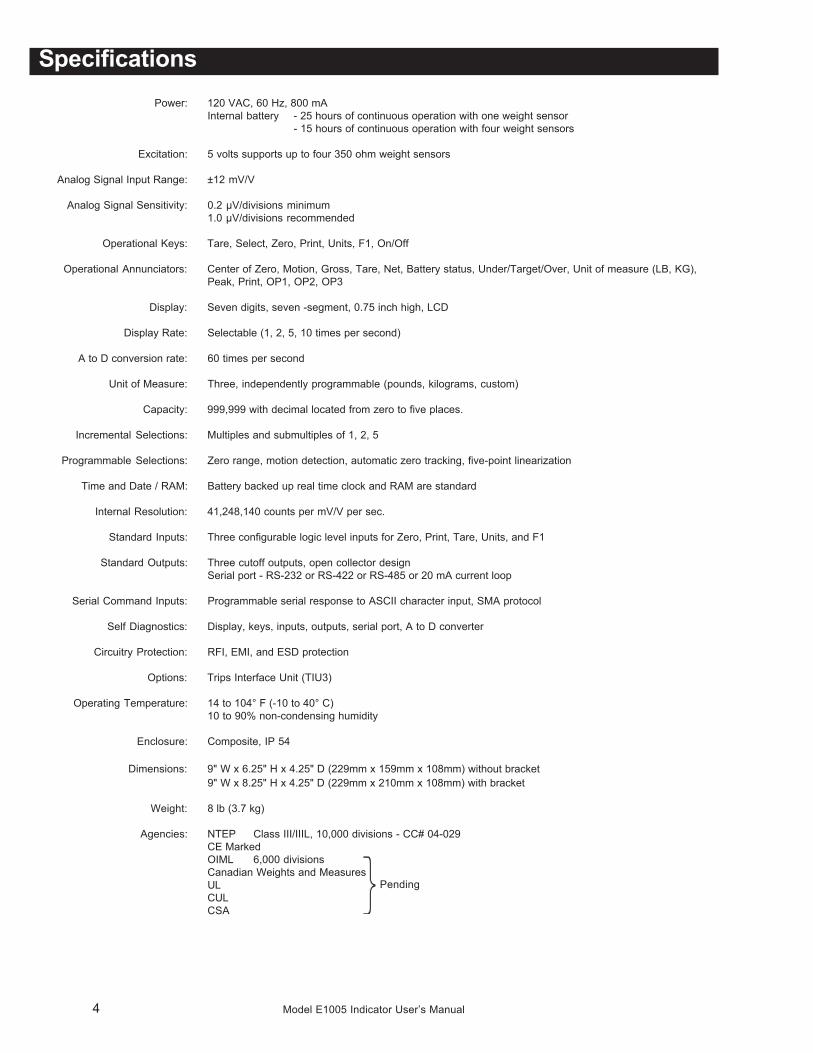
SpecificationsPower: 120 VAC, 60 Hz, 800 mA
Internal battery - 25 hours of continuous operation with one weight sensor- 15 hours of continuous operation with four weight sensors
Excitation: 5 volts supports up to four 350 ohm weight sensors
Analog Signal Input Range: ±12 mV/V
Analog Signal Sensitivity: 0.2 µV/divisions minimum1.0 µV/divisions recommended
Operational Keys: Tare, Select, Zero, Print, Units, F1, On/Off
Operational Annunciators: Center of Zero, Motion, Gross, Tare, Net, Battery status, Under/Target/Over, Unit of measure (LB, KG),Peak, Print, OP1, OP2, OP3
Display: Seven digits, seven -segment, 0.75 inch high, LCD
Display Rate: Selectable (1, 2, 5, 10 times per second)
A to D conversion rate: 60 times per second
Unit of Measure: Three, independently programmable (pounds, kilograms, custom)
Capacity: 999,999 with decimal located from zero to five places.
Incremental Selections: Multiples and submultiples of 1, 2, 5
Programmable Selections: Zero range, motion detection, automatic zero tracking, five-point linearization
Time and Date / RAM: Battery backed up real time clock and RAM are standard
Internal Resolution: 41,248,140 counts per mV/V per sec.
Standard Inputs: Three configurable logic level inputs for Zero, Print, Tare, Units, and F1
Standard Outputs: Three cutoff outputs, open collector designSerial port - RS-232 or RS-422 or RS-485 or 20 mA current loop
Serial Command Inputs: Programmable serial response to ASCII character input, SMA protocol
Self Diagnostics: Display, keys, inputs, outputs, serial port, A to D converter
Circuitry Protection: RFI, EMI, and ESD protection
Options: Trips Interface Unit (TIU3)
Operating Temperature: 14 to 104° F (-10 to 40° C)10 to 90% non-condensing humidity
Enclosure: Composite, IP 54
Dimensions: 9" W x 6.25" H x 4.25" D (229mm x 159mm x 108mm) without bracket9" W x 8.25" H x 4.25" D (229mm x 210mm x 108mm) with bracket
Weight: 8 lb (3.7 kg)
Agencies: NTEP Class III/IIIL, 10,000 divisions - CC# 04-029CE MarkedOIML 6,000 divisionsCanadian Weights and MeasuresULCULCSA
Pending
5Model E1005 Indicator User’s Manual
IntroductionThe Model E1005 is an easy to use, uncomplicated indicator for generalweighing applications. It is ideal for bench scales, floor scales and tankweighing applications. The display includes a multi-segment fan graph forfast visual awareness for checkweighing. Also, the indicator can performcounting functions, peak weight functions, act as a remote display andoperate on battery power.
Communication port allows connection to a printer, remote display orcomputer. The indicator also has three setpoint controls and can accommo-date a footswitch for zero, print or tare function.
All this in an IP54 rated enclosure.
Major sections of this manual are headed by titles in a black bar like Intro-duction above. Subheadings appear in the left column. Instructions and textappear on the right side of the page. Occasionally notes, tips, and specialinstructions appear in the left column.
Unpack your indicator and check for any shipping damage. If shippingdamage is found, save all packing materials and contact the shippingcompany immediately.
1. Use the included hardware and attach the indicator to the bracket.
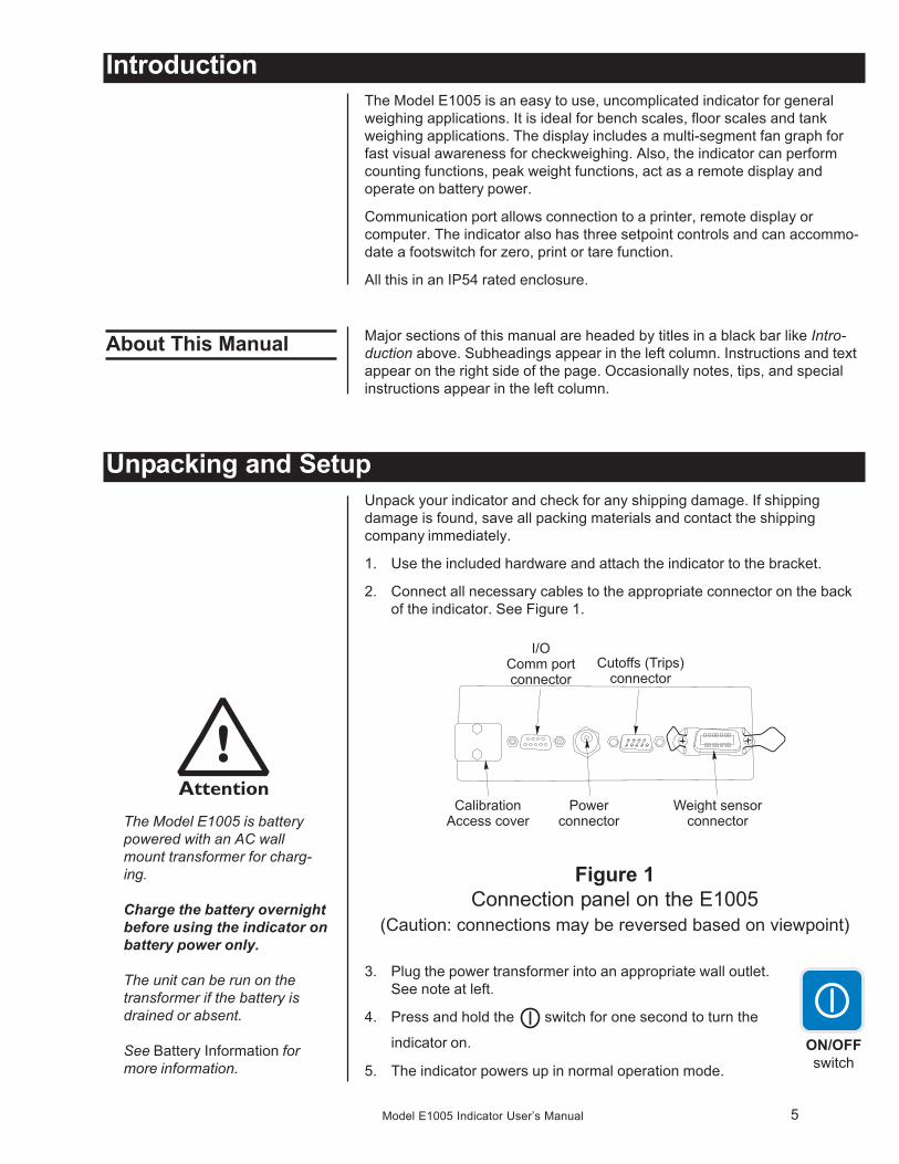
2. Connect all necessary cables to the appropriate connector on the backof the indicator. See Figure 1.
Figure 1Connection panel on the E1005
(Caution: connections may be reversed based on viewpoint)
3. Plug the power transformer into an appropriate wall outlet.See note at left.
4. Press and hold the switch for one second to turn the
indicator on.
5. The indicator powers up in normal operation mode.
Unpacking and Setup
ON/OFFswitch
About This Manual
The Model E1005 is batterypowered with an AC wallmount transformer for charg-ing.
Charge the battery overnightbefore using the indicator onbattery power only.
The unit can be run on thetransformer if the battery isdrained or absent.
See Battery Information formore information.
6 Model E1005 Indicator User’s Manual
Keys There are seven keys on the front panel. Their functions are listed below.
Front Panel
Never press a key with any-thing but your finger. Damageto the overlay may result ifsharp or rough objects areused.
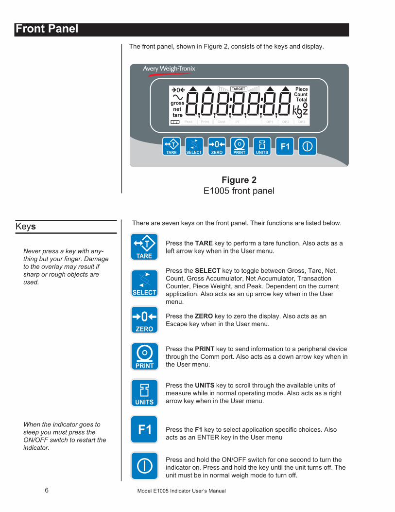
The front panel, shown in Figure 2, consists of the keys and display.
Figure 2E1005 front panel
Press the TARE key to perform a tare function. Also acts as aleft arrow key when in the User menu.
Press the SELECT key to toggle between Gross, Tare, Net,Count, Gross Accumulator, Net Accumulator, TransactionCounter, Piece Weight, and Peak. Dependent on the currentapplication. Also acts as an up arrow key when in the Usermenu.
Press the ZERO key to zero the display. Also acts as anEscape key when in the User menu.
Press the PRINT key to send information to a peripheral devicethrough the Comm port. Also acts as a down arrow key when inthe User menu.
Press the UNITS key to scroll through the available units ofmeasure while in normal operating mode. Also acts as a rightarrow key when in the User menu.
Press the F1 key to select application specific choices. Alsoacts as an ENTER key in the User menu
Press and hold the ON/OFF switch for one second to turn theindicator on. Press and hold the key until the unit turns off. Theunit must be in normal weigh mode to turn off.
When the indicator goes tosleep you must press theON/OFF switch to restart theindicator.
7Model E1005 Indicator User’s Manual
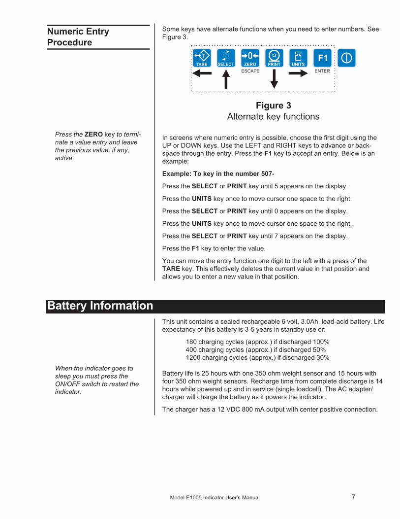
Some keys have alternate functions when you need to enter numbers. SeeFigure 3.
Figure 3Alternate key functions
In screens where numeric entry is possible, choose the first digit using theUP or DOWN keys. Use the LEFT and RIGHT keys to advance or back-space through the entry. Press the F1 key to accept an entry. Below is anexample:
Example: To key in the number 507-
Press the SELECT or PRINT key until 5 appears on the display.
Press the UNITS key once to move cursor one space to the right.
Press the SELECT or PRINT key until 0 appears on the display.
Press the UNITS key once to move cursor one space to the right.
Press the SELECT or PRINT key until 7 appears on the display.
Press the F1 key to enter the value.
You can move the entry function one digit to the left with a press of theTARE key. This effectively deletes the current value in that position andallows you to enter a new value in that position.
Numeric EntryProcedure
Press the ZERO key to termi-nate a value entry and leavethe previous value, if any,active
Battery InformationThis unit contains a sealed rechargeable 6 volt, 3.0Ah, lead-acid battery. Lifeexpectancy of this battery is 3-5 years in standby use or:
180 charging cycles (approx.) if discharged 100%400 charging cycles (approx.) if discharged 50%1200 charging cycles (approx.) if discharged 30%
Battery life is 25 hours with one 350 ohm weight sensor and 15 hours withfour 350 ohm weight sensors. Recharge time from complete discharge is 14hours while powered up and in service (single loadcell). The AC adapter/charger will charge the battery as it powers the indicator.
The charger has a 12 VDC 800 mA output with center positive connection.
When the indicator goes tosleep you must press theON/OFF switch to restart theindicator.
8 Model E1005 Indicator User’s Manual
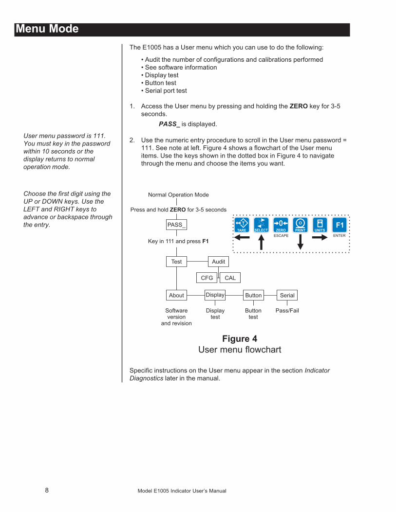
Menu ModeThe E1005 has a User menu which you can use to do the following:
• Audit the number of configurations and calibrations performed• See software information• Display test• Button test• Serial port test
1. Access the User menu by pressing and holding the ZERO key for 3-5seconds.
PASS_ is displayed.
2. Use the numeric entry procedure to scroll in the User menu password =111. See note at left. Figure 4 shows a flowchart of the User menuitems. Use the keys shown in the dotted box in Figure 4 to navigatethrough the menu and choose the items you want.
Figure 4User menu flowchart
Specific instructions on the User menu appear in the section IndicatorDiagnostics later in the manual.
User menu password is 111.You must key in the passwordwithin 10 seconds or thedisplay returns to normaloperation mode.
Choose the first digit using theUP or DOWN keys. Use theLEFT and RIGHT keys toadvance or backspace throughthe entry.
9Model E1005 Indicator User’s Manual
Indicator Operations
Gross Weighing
Tare/Net Weighing
To change unit of measure,press the UNITS key.
The E1005 comes equipped with several weighing applications;• Accumulator weighing (default setting)• Batch weighing• Checkweigher• Counting• Peak capture• Remote display
These different applications are activated using a password protectedService menu. See the Service Manual for instructions on changing applica-tions and clearing accumulators.
The accumulator application comes as the default application. You can dogross weighments, tare/net weighments and accumulator functions. Beloware instructions for each.
To perform gross weighing, power up the unit and follow these steps:
1. Empty the scale and press ZERO key to zero the display. . .0 is displayed and gross and center of zero annunciators are lit.
2. Place item to be weighed on the scale. . .Weight is displayed.
To perform a net weighment, power up the unit and follow these steps:
1. Empty the scale and press ZERO key to zero the display. . .0 is displayed and gross and center of zero annunciators are lit.
2. Place item to be tared on the scale. . .Weight is displayed.
3. Press the TARE key. . .0 is displayed and net annunciator is lit.
4. Place material to be weighed on the scale. . .Net weight of material is displayed and net annunciator is lit.
5. Press the SELECT key to scroll through gross, tare, and net modes.Remove the weight from the scale and press TARE to return to grossmode.
When the indicator goes tosleep you must press theON/OFF switch to restart theindicator.
10 Model E1005 Indicator User’s Manual
The accumulator is memory that collects individual weighments (gross andnet) and stores the totals. These totals can be recalled at any time and thenumber of weighments included in the totals can be displayed. With theproper password all information can be deleted. See the Service Manual.
The accumulator maximum is 999,999. It does not rollover and start over at0.
To use the accumulator, power up the unit and follow these steps:
1. Empty the scale and press ZERO key to zero the display. . .0 is displayed and gross and center of zero annunciators are lit.
2. Place item on the scale. . .Weight is displayed.
3. You can press the PRINT or F1 key to add weight to the accumulator. Ifyou press PRINT, the weight is accumulated and the informationprinted. If you press F1, the weight is accumulated. Scale weight mustreturn to zero before another weighment can be accumulated.
4. Repeat 2 and 3 for each weighment you want to accumulate.
5. To review the accumulator total and the number of weighments, removeall weight from the scale and press the SELECT key repeatedly. . .
1st press = Net weight displayed2nd press = Tare weight displayed3rd press = Gross total of all weighments is displayed4th press = Net total of all weighments is displayed5th press = Number of weighments is displayed6th press = Display returns to gross weigh mode
You need the supervisor’s password to clear the accumulator. See theService Manual for instructions.
AccumulatorWeighing
The Accumulator applicationcomes as the default activeapplication in the E1005.
You can use tare/net weighingwith the accumulator applica-tion. The accumulator storesboth gross and net totals forlater recall.
Choose the first digit using theUP or DOWN keys. Use theLEFT and RIGHT keys toadvance or backspace throughthe entry.
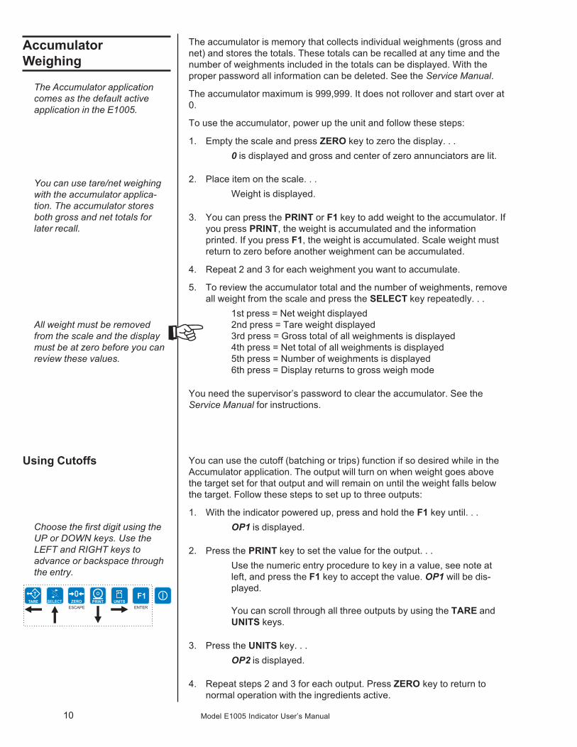
You can use the cutoff (batching or trips) function if so desired while in theAccumulator application. The output will turn on when weight goes abovethe target set for that output and will remain on until the weight falls belowthe target. Follow these steps to set up to three outputs:
1. With the indicator powered up, press and hold the F1 key until. . .OP1 is displayed.
2. Press the PRINT key to set the value for the output. . .Use the numeric entry procedure to key in a value, see note atleft, and press the F1 key to accept the value. OP1 will be dis-played.
You can scroll through all three outputs by using the TARE andUNITS keys.
3. Press the UNITS key. . .OP2 is displayed.
4. Repeat steps 2 and 3 for each output. Press ZERO key to return tonormal operation with the ingredients active.
Using Cutoffs
All weight must be removedfrom the scale and the displaymust be at zero before you canreview these values.
11Model E1005 Indicator User’s Manual
Checkweighing
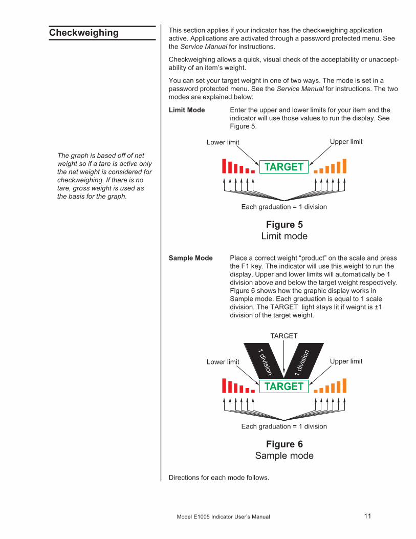
The graph is based off of netweight so if a tare is active onlythe net weight is considered forcheckweighing. If there is notare, gross weight is used asthe basis for the graph.
This section applies if your indicator has the checkweighing applicationactive. Applications are activated through a password protected menu. Seethe Service Manual for instructions.
Checkweighing allows a quick, visual check of the acceptability or unaccept-ability of an item’s weight.
You can set your target weight in one of two ways. The mode is set in apassword protected menu. See the Service Manual for instructions. The twomodes are explained below:
Limit Mode Enter the upper and lower limits for your item and theindicator will use those values to run the display. SeeFigure 5.
Figure 5Limit mode
Sample Mode Place a correct weight “product” on the scale and pressthe F1 key. The indicator will use this weight to run thedisplay. Upper and lower limits will automatically be 1division above and below the target weight respectively.Figure 6 shows how the graphic display works inSample mode. Each graduation is equal to 1 scaledivision. The TARGET light stays lit if weight is ±1division of the target weight.
Figure 6Sample mode
Directions for each mode follows.
12 Model E1005 Indicator User’s Manual
Sample Mode: UsingProduct to Set TargetWeight
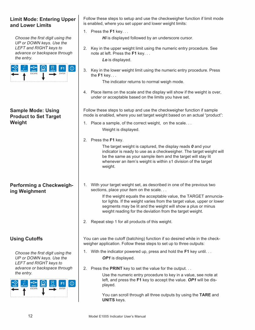
Follow these steps to setup and use the checkweigher function if limit modeis enabled, where you set upper and lower weight limits:
1. Press the F1 key. . .Hi is displayed followed by an underscore cursor.
2. Key in the upper weight limit using the numeric entry procedure. Seenote at left. Press the F1 key. . .
Lo is displayed.
3. Key in the lower weight limit using the numeric entry procedure. Pressthe F1 key. . .
The indicator returns to normal weigh mode.
4. Place items on the scale and the display will show if the weight is over,under or acceptable based on the limits you have set.
Follow these steps to setup and use the checkweigher function if samplemode is enabled, where you set target weight based on an actual “product”:
1. Place a sample, of the correct weight, on the scale. . .Weight is displayed.
2. Press the F1 key.The target weight is captured, the display reads 0 and yourindicator is ready to use as a checkweigher. The target weight willbe the same as your sample item and the target will stay litwhenever an item’s weight is within ±1 division of the targetweight.
1. With your target weight set, as described in one of the previous twosections, place your item on the scale. . .
If the weight equals the acceptable value, the TARGET annuncia-tor lights. If the weight varies from the target value, upper or lowersegments may be lit and the weight will show a plus or minusweight reading for the deviation from the target weight.
2. Repeat step 1 for all products of this weight.
You can use the cutoff (batching) function if so desired while in the check-weigher application. Follow these steps to set up to three outputs:
1. With the indicator powered up, press and hold the F1 key until. . .OP1 is displayed.
2. Press the PRINT key to set the value for the output. . .Use the numeric entry procedure to key in a value, see note atleft, and press the F1 key to accept the value. OP1 will be dis-played.
You can scroll through all three outputs by using the TARE andUNITS keys.
Performing a Checkweigh-ing Weighment
Choose the first digit using theUP or DOWN keys. Use theLEFT and RIGHT keys toadvance or backspace throughthe entry.
Using Cutoffs
Limit Mode: Entering Upperand Lower Limits
Choose the first digit using theUP or DOWN keys. Use theLEFT and RIGHT keys toadvance or backspace throughthe entry.
13Model E1005 Indicator User’s Manual
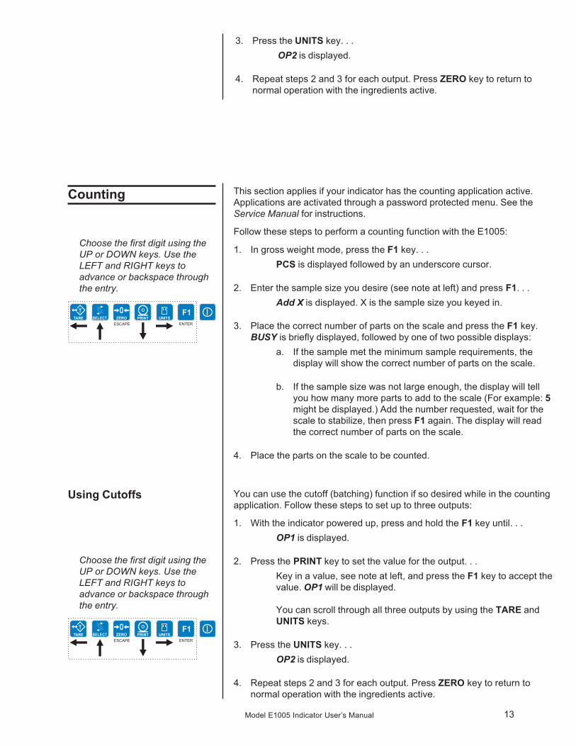
Counting This section applies if your indicator has the counting application active.Applications are activated through a password protected menu. See theService Manual for instructions.
Follow these steps to perform a counting function with the E1005:
1. In gross weight mode, press the F1 key. . .PCS is displayed followed by an underscore cursor.
2. Enter the sample size you desire (see note at left) and press F1. . .Add X is displayed. X is the sample size you keyed in.
3. Place the correct number of parts on the scale and press the F1 key.BUSY is briefly displayed, followed by one of two possible displays:
a. If the sample met the minimum sample requirements, thedisplay will show the correct number of parts on the scale.
b. If the sample size was not large enough, the display will tellyou how many more parts to add to the scale (For example: 5might be displayed.) Add the number requested, wait for thescale to stabilize, then press F1 again. The display will readthe correct number of parts on the scale.
4. Place the parts on the scale to be counted.
Choose the first digit using theUP or DOWN keys. Use theLEFT and RIGHT keys toadvance or backspace throughthe entry.
Choose the first digit using theUP or DOWN keys. Use theLEFT and RIGHT keys toadvance or backspace throughthe entry.
You can use the cutoff (batching) function if so desired while in the countingapplication. Follow these steps to set up to three outputs:
1. With the indicator powered up, press and hold the F1 key until. . .OP1 is displayed.
2. Press the PRINT key to set the value for the output. . .Key in a value, see note at left, and press the F1 key to accept thevalue. OP1 will be displayed.
You can scroll through all three outputs by using the TARE andUNITS keys.
3. Press the UNITS key. . .OP2 is displayed.
4. Repeat steps 2 and 3 for each output. Press ZERO key to return tonormal operation with the ingredients active.
Using Cutoffs
3. Press the UNITS key. . .OP2 is displayed.
4. Repeat steps 2 and 3 for each output. Press ZERO key to return tonormal operation with the ingredients active.
14 Model E1005 Indicator User’s Manual
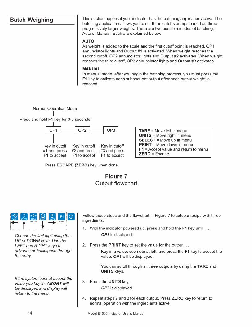
Batch Weighing This section applies if your indicator has the batching application active. Thebatching application allows you to set three cutoffs or trips based on threeprogressively larger weights. There are two possible modes of batching;Auto or Manual. Each are explained below.
AUTOAs weight is added to the scale and the first cutoff point is reached, OP1annunciator lights and Output #1 is activated. When weight reaches thesecond cutoff, OP2 annunciator lights and Output #2 activates. When weightreaches the third cutoff, OP3 annunciator lights and Output #3 activates.
MANUALIn manual mode, after you begin the batching process, you must press theF1 key to activate each subsequent output after each output weight isreached.
Choose the first digit using theUP or DOWN keys. Use theLEFT and RIGHT keys toadvance or backspace throughthe entry.
Figure 7Output flowchart
Follow these steps and the flowchart in Figure 7 to setup a recipe with threeingredients:
1. With the indicator powered up, press and hold the F1 key until. . .OP1 is displayed.
2. Press the PRINT key to set the value for the output. . .Key in a value, see note at left, and press the F1 key to accept thevalue. OP1 will be displayed.
You can scroll through all three outputs by using the TARE andUNITS keys.
3. Press the UNITS key. . .OP2 is displayed.
4. Repeat steps 2 and 3 for each output. Press ZERO key to return tonormal operation with the ingredients active.
If the system cannot accept thevalue you key in, ABORT willbe displayed and display willreturn to the menu.
15Model E1005 Indicator User’s Manual
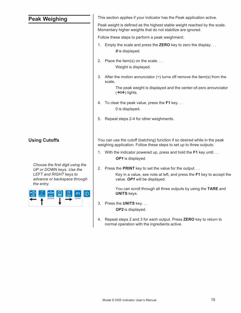
Peak Weighing This section applies if your indicator has the Peak application active.
Peak weight is defined as the highest stable weight reached by the scale.Momentary higher weights that do not stabilize are ignored.
Follow these steps to perform a peak weighment:
1. Empty the scale and press the ZERO key to zero the display. . .0 is displayed.
2. Place the item(s) on the scale. . .Weight is displayed.
3. After the motion annunciator (~) turns off remove the item(s) from thescale,
The peak weight is displayed and the center-of-zero annunciator( ) lights.
4. To clear the peak value, press the F1 key. . .0 is displayed.
5. Repeat steps 2-4 for other weighments.
You can use the cutoff (batching) function if so desired while in the peakweighing application. Follow these steps to set up to three outputs:
1. With the indicator powered up, press and hold the F1 key until. . .OP1 is displayed.
2. Press the PRINT key to set the value for the output. . .Key in a value, see note at left, and press the F1 key to accept thevalue. OP1 will be displayed.
You can scroll through all three outputs by using the TARE andUNITS keys.
3. Press the UNITS key. . .OP2 is displayed.
4. Repeat steps 2 and 3 for each output. Press ZERO key to return tonormal operation with the ingredients active.
Choose the first digit using theUP or DOWN keys. Use theLEFT and RIGHT keys toadvance or backspace throughthe entry.
Using Cutoffs
16 Model E1005 Indicator User’s Manual
The E1005 provides an RS-232 output for data transmission to a peripheraldevice. Refer to the Service Manual for RS-232 interface connections.
If your indicator has a peripheral device connected, from the gross/netweighing mode press the PRINT key to transmit the selected output(s).
The PRINT annunciator will illuminate while data is transmitted and the dataconfigured to be printed will be output to the printer.
Print Format #1 for weighing applications
G 1234.56 lb<CR><LF>
T 34.56 lb<CR><LF>
N 1200.00 lb<CR><LF>
Print Format #1 for counting application
Count: 12230
Print Format #1 for peak application
12230 lb<CR>
Communications
The default serial port param-eters are 9600 baud, 8 dat-abits, no parity and 1 stop bit.
Error Messages
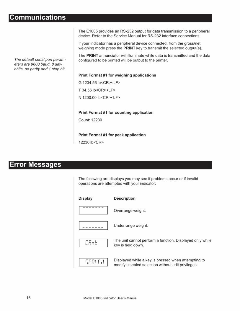
The following are displays you may see if problems occur or if invalidoperations are attempted with your indicator:
Display Description
Overrange weight.
Underrange weight.
The unit cannot perform a function. Displayed only whilekey is held down.
Displayed while a key is pressed when attempting tomodify a sealed selection without edit privileges.
17Model E1005 Indicator User’s Manual
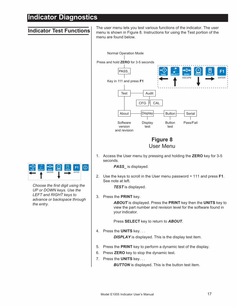
The user menu lets you test various functions of the indicator. The usermenu is shown in Figure 8. Instructions for using the Test portion of themenu are found below.
Figure 8User Menu
1. Access the User menu by pressing and holding the ZERO key for 3-5seconds.
PASS_ is displayed.
2. Use the keys to scroll in the User menu password = 111 and press F1.See note at left.
TEST is displayed.
3. Press the PRINT key.ABOUT is displayed. Press the PRINT key then the UNITS key toview the part number and revision level for the software found inyour indicator.
Press SELECT key to return to ABOUT.
4. Press the UNITS key. . .DISPLAY is displayed. This is the display test item.
5. Press the PRINT key to perform a dynamic test of the display.6. Press ZERO key to stop the dynamic test.7. Press the UNITS key. . .
BUTTON is displayed. This is the button test item.
Indicator Diagnostics
Indicator Test Functions
Choose the first digit using theUP or DOWN keys. Use theLEFT and RIGHT keys toadvance or backspace throughthe entry.
18 Model E1005 Indicator User’s Manual
8. Press the PRINT key to perform a button test. Each key you press willbe reflected on the display screen to confirm the button is functioningcorrectly.
9. Press ZERO key to stop the button test.BUTTON is displayed.
10. Press the UNITS key. . .SERIAL is displayed. This is the serial test item. To test the serialport, jumper the TX and RX lines. Continue to step 11.
11. Press the PRINT key to access the serial test.The display will show PASS if the serial port is working properly. Ifthere is a problem the display will show FAIL.
12. Press ZERO key to exit the serial test.SERIAL is displayed.
13. Press the ZERO key to return to normal operation mode.
19Model E1005 Indicator User’s Manual
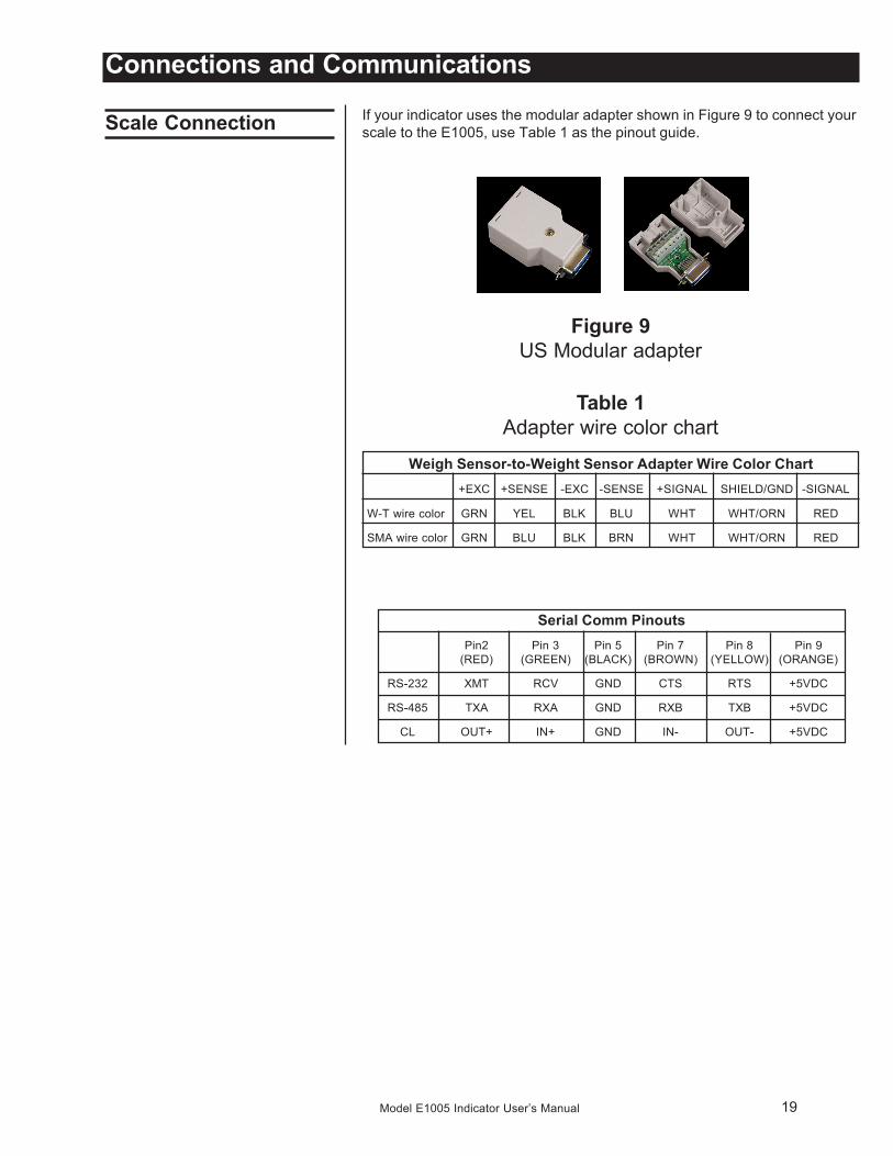
Weigh Sensor-to-Weight Sensor Adapter Wire Color Chart+EXC +SENSE -EXC -SENSE +SIGNAL SHIELD/GND -SIGNAL
W-T wire color GRN YEL BLK BLU WHT WHT/ORN RED
SMA wire color GRN BLU BLK BRN WHT WHT/ORN RED
Connections and Communications
Scale Connection If your indicator uses the modular adapter shown in Figure 9 to connect yourscale to the E1005, use Table 1 as the pinout guide.
Figure 9US Modular adapter
Table 1Adapter wire color chart
Serial Comm PinoutsPin2 Pin 3 Pin 5 Pin 7 Pin 8 Pin 9
(RED) (GREEN) (BLACK) (BROWN) (YELLOW) (ORANGE)
RS-232 XMT RCV GND CTS RTS +5VDC
RS-485 TXA RXA GND RXB TXB +5VDC
CL OUT+ IN+ GND IN- OUT- +5VDC
20 Model E1005 Indicator User’s Manual
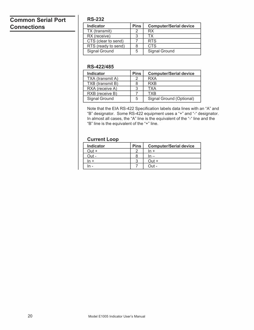
RS-232Indicator Pins Computer/Serial deviceTX (transmit) 2 RXRX (receive) 3 TXCTS (clear to send) 7 RTSRTS (ready to send) 8 CTSSignal Ground 5 Signal Ground
RS-422/485Indicator Pins Computer/Serial deviceTXA (transmit A) 2 RXATXB (transmit B) 8 RXBRXA (receive A) 3 TXARXB (receive B) 7 TXBSignal Ground 5 Signal Ground (Optional)
Note that the EIA RS-422 Specification labels data lines with an “A” and“B” designator. Some RS-422 equipment uses a “+” and “-“ designator.In almost all cases, the “A” line is the equivalent of the “-“ line and the“B” line is the equivalent of the “+” line.
Current LoopIndicator Pins Computer/Serial deviceOut + 2 In +Out - 8 In –In + 3 Out +In - 7 Out -
Common Serial PortConnections

21Model E1005 Indicator User’s Manual

22 Model E1005 Indicator User’s Manual

23Model E1005 Indicator User’s Manual

Weigh Bar® is a registered trademarkof Avery Weigh-Tronix and may beregistered in certain jurisdictions.
All brands and product names usedwithin this document are trademarksor registered trademarks of their respective holders.
Avery Weigh-Tronix USA1000 Armstrong Dr.Fairmont, MN 56031 USATelephone: 507-238-4461Facsimile: 507-238-4195e-mail: [email protected]
Avery Weigh-Tronix UKFoundry LaneSmethwick, West MidlandsEngland B66 2LPTel: +44 870 90 34343Fax: +44 121 224 8183Email: [email protected] site:www.averyweigh-tronix.com
Avery Weigh-Tronix Canada, ULC217 Brunswick BoulevardPointe Claire, QC H9R 4R7 CanadaTelephone: 514-695-0380Toll free: 800-561-9461Facsimile: 514-695-6820www.weigh-tronix.ca


