Model DV-5 Deluge Valve, Diaphragm Style, 1-1/2...
42
General Description The 1-1/2 thru 8 inch (DN40 thru DN200), Model DV-5 Deluge Valves are diaphragm type valves designed for vertical or horizontal installation and for fire protection system service. They are used as “automatic water control valves” in deluge, preaction, and special types of fire protection sys- tems such as foam-water and double interlock systems. When properly trimmed, the DV-5 Valves are also able to provide actuation of fire alarms upon system operation. The diaphragm style design of the DV-5 Valve allows external resetting — providing for easy resetting of a deluge or preaction system without having to open a valve handhole cover to manually reposition a clapper and/or latch mechanism. Simply re- pressurizing the diaphragm chamber resets the valve. The one-piece, diaphragm style de- sign of the DV-5 also allows internal and external coating of the valve to provide corrosion resistance. The in- ternal corrosion resistance offered by the Rilsan coating makes the DV-5 suitable for most seawater and brack- ish water supplies when utilized in del- uge systems. The external corrosion resistance of the Rilsan coating per- mits the use of the DV-5 in corrosive atmospheres associated with many types of industrial processing plants and outdoor installations. WARNING The Model DV-5 Deluge Valves de- scribed herein must be installed and maintained in compliance with this document, as well as with the applica- ble standards of the National Fire Pro- tection Association, in addition to the standards of any other authorities hav- ing jurisdiction. Failure to do so may impair the performance of these de- vices. The owner is responsible for maintain- ing their fire protection system and de- vices in proper operating condition. The installing contractor or manufac- turer should be contacted with any questions. Page 1 of 8 TFP1305 MARCH, 2006 Model DV-5 Deluge Valve, Diaphragm Style, 1-1/2 thru 8 Inch (DN40 thru DN200), 250 psi (17,2 bar) Vertical or Horizontal Installation Technical Services: Tel: (800) 381-9312 / Fax: (800) 791-5500 Outlet Inlet 1-1/2 Inch (DN40) 2 Inch (DN50) 3 Inch (DN80) 4 Inch (DN100) 6 Inch (DN150) 8 Inch (DN200) Nominal Valve Size End Connection Thread Thread Groove Groove Groove Flange Flange Flange End Connections Available and Weights N/A N/A N/A N/A N/A N/A N/A N/A 9 lbs. (4,1 Kg) 8 lbs. (3,6 Kg) 12 lbs. (5,4 Kg) 10 lbs. (4,5 Kg) 31 lbs. (14,1 Kg) 39 lbs. (17,7 Kg) 47 lbs. (21,3 Kg) 80 lbs. (36,3 Kg) 74 lbs. (33,6 Kg) 61 lbs. (27,7 Kg) 99 lbs. (44,9 Kg) 107 lbs. (48,5 Kg) 115 lbs. (52,3 Kg) 150 lbs. (68,1 Kg) The Grooved Outlet is recommended for use in Preaction Systems to accommodate the * use of a Groove x Groove Riser Check Valve. Refer to Technical Data Sheet TFP1410, TFP1415, TFP1420, TFP1460, or TFP1465 as applicable. * * 170 lbs. (77,8 Kg) 190 lbs. (87,5 Kg) Customer Service/Sales: Tel: (414) 570-5000 / (800) 558-5236 Fax: (414) 570-5010 / (800) 877-1295
-
Upload
nguyendieu -
Category
Documents
-
view
254 -
download
1
Transcript of Model DV-5 Deluge Valve, Diaphragm Style, 1-1/2...

GeneralDescriptionThe 1-1/2 thru 8 inch (DN40 thruDN200), Model DV-5 Deluge Valvesare diaphragm type valves designedfor vertical or horizontal installationand for fire protection system service.They are used as “automatic watercontrol valves” in deluge, preaction,and special types of fire protection sys-tems such as foam-water and doubleinterlock systems. When properlytrimmed, the DV-5 Valves are alsoable to provide actuation of fire alarmsupon system operation.
The diaphragm style design of theDV-5 Valve allows external resetting— providing for easy resetting of adeluge or preaction system withouthaving to open a valve handhole coverto manually reposition a clapperand/or latch mechanism. Simply re-pressurizing the diaphragm chamberresets the valve.
The one-piece, diaphragm style de-sign of the DV-5 also allows internaland external coating of the valve toprovide corrosion resistance. The in-ternal corrosion resistance offered bythe Rilsan coating makes the DV-5suitable for most seawater and brack-ish water supplies when utilized in del-uge systems. The external corrosionresistance of the Rilsan coating per-mits the use of the DV-5 in corrosiveatmospheres associated with manytypes of industrial processing plantsand outdoor installations.
WARNINGThe Model DV-5 Deluge Valves de-scribed herein must be installed andmaintained in compliance with thisdocument, as well as with the applica-ble standards of the National Fire Pro-tection Association, in addition to thestandards of any other authorities hav-ing jurisdiction. Failure to do so mayimpair the performance of these de-vices.
The owner is responsible for maintain-ing their fire protection system and de-vices in proper operating condition.
The installing contractor or manufac-turer should be contacted with anyquestions.
Page 1 of 8 TFP1305MARCH, 2006
Model DV-5 Deluge Valve, Diaphragm Style,1-1/2 thru 8 Inch (DN40 thru DN200), 250 psi (17,2 bar)Vertical or Horizontal Installation
Technical Services: Tel: (800) 381-9312 / Fax: (800) 791-5500
OutletInlet1-1/2 Inch
(DN40)2 Inch(DN50)
3 Inch(DN80)
4 Inch(DN100)
6 Inch(DN150)
8 Inch(DN200)
Nominal Valve SizeEnd Connection
ThreadThread
GrooveGroove
GrooveFlange
FlangeFlange
End Connections Available and Weights
N/AN/A N/AN/A
N/AN/A
N/AN/A
9 lbs.(4,1 Kg)
8 lbs.(3,6 Kg)
12 lbs.(5,4 Kg)
10 lbs.(4,5 Kg)
31 lbs.(14,1 Kg)
39 lbs.(17,7 Kg)
47 lbs.(21,3 Kg)
80 lbs.(36,3 Kg)
74 lbs.(33,6 Kg)
61 lbs.(27,7 Kg)
99 lbs.(44,9 Kg)
107 lbs.(48,5 Kg)
115 lbs.(52,3 Kg)
150 lbs.(68,1 Kg)
The Grooved Outlet is recommended for use in Preaction Systems to accommodate the*use of a Groove x Groove Riser Check Valve. Refer to Technical Data Sheet TFP1410,TFP1415, TFP1420, TFP1460, or TFP1465 as applicable.
*
* 170 lbs.(77,8 Kg)
190 lbs.(87,5 Kg)
Customer Service/Sales:Tel: (414) 570-5000 / (800) 558-5236
Fax: (414) 570-5010 / (800) 877-1295

FIGURE 11-1/2 thru 8 INCH (DN40 thru DN200) MODEL DV-5 DELUGE VALVE
— ASSEMBLY —
DIAPHRAGMORIENTATION
TAB
TAB ORIENTEDPERPENDICULARTO VALVE BODY
DIAPHRAGM
3
Hex Bolt,
4 Inch Valve, M16 x 506 Inch Valve, M16 x 55 CH6. .
CH6. .
5
M16 x 50 CH4. . . . . . . . . . . . .2 & 3 Inch Valves,M12 x 30 CH4. . . . . . . . . . . . .1-1/2 Inch Valve,
6(4, 6, & 8 INCH
VALVESONLY)
Hex Nut,6
5
4
1.NOTES:
NR - Not Replaceable.
STUDS,SEE NOTE 2
2
1
8 Inch Valve, M20 x 70 CH6. .
CH2. .4 & 6 Inch Valves, M16CH2. . . . .8 Inch Valves, M20
NO.
(a)
DESCRIPTION P/N
REPLACEMENT PARTS
Diaphragm Kit, Includes Item 292-477-1-1051-1/2 Inch Valve . . . . . . . . . . .92-477-1-1072 Inch Valve92-477-1-109
. . . . . . . . . . . . . .3 Inch Valve . . . . . . . . . . . . . .
92-477-1-1014 Inch Valve . . . . . . . . . . . . . .6 Inch Valve 92-477-1-103. . . . . . . . . . . . . .8 Inch Valve 92-477-1-111. . . . . . . . . . . . . .
Handhole Cover NR1. . . . . . .4 Flat Washer,
NO.
1
QTY.DESCRIPTION Refer to Kit
(a)Valve Body
1Diaphragm . . . . . . . . . . .NR1. . . . . . . . . . .
23
VALVE PARTS
1-1/2 Inch Valve, M12 CH4. . .CH4. .2 & 3 Inch Valves, M16CH8. .4 & 6 Inch Valves, M16CH8. . . . .8 Inch Valves, M20
2. 4, 6, & 8 Inch Valve Bodies are equippedwith studs as shown, allowing Diaphragmand Handhole Cover to be "hung" in placeto ease assembly. Bodies of 1-1/2, 2, and 3Inch Valves are not equipped with studs.
4
Page 2 of 8 TFP1305
TABLE A — DIMENSIONAL SPECIFICATIONS FOR SELECTION OF FLANGE DRILLING
Same drilling as for BS 4504 Section 3.2 (PN16) and DIN 2532 (PN16).
ANSI B16.1 AS 2129ISO 7005-2 JIS B 2210(Class 125) (Table E)(PN10) (10K)3
A
7.50
9.50(190,5)
(241,3)
B
0.75
0.88(19,0)
(22,2)
7.00
9.25(178,0)
(235,0)
0.71
0.87(18,0)
(22,0)
6.89(175,0)
Flange Drilling SpecificationNominal Dimensions in Inches and (mm)
0.60(15,0)
9.45(240,0)
11.75(298,5)
0.88(22,2)
11.50(292,0)
0.87(22,0)
11.61(295,0)
0.75(19,0)
0.91(23,0)
Valve
4 Inch
6 Inch(DN100)
(DN150)8 Inch
(DN200)
3 Inch(DN80)
N
4
8
8
8
A B N
8
ISO 7005-2(PN16)
7.09
9.45(180,0)
(240,0)
0.75(19,0)
11.61(295,0)
0.75(19,0)
A B N
8
8
8
12
ISO 2084(PN16)
USE
A B N
8
8
A B N
8
8
8
Dim. Dim.
Nominal
Qty. Dim. Dim. Qty. Dim. Dim. Qty. Dim. Dim. Qty. Dim. Dim. Qty.
Same drilling as for BS 4504 Section 3.2 (PN10) and DIN 2532 (PN10).Dim. A
Bolt CircleDiameter
Dim. BBolt HoleDiameter
Qty. NNumber ofBolt Holes
4
3
4
6.00(152,4)
6.30(160,0)
Size 1
Flange end 1-1/2 & 2 Inch (DN40 & DN50) DV-5 Valves are not offered.1
N/A
N/A N/A
2
Same drilling as for B16.5 (Class 150) and B16.42 (Class 250).2
0.91(23,0)
0.91(23,0)
0.75(19,0)

Page 3 of 8TFP1305
FIGURE 21-1/2 thru 8 INCH (DN40 thru DN200) MODEL DV-5 DELUGE VALVE
— SET AND OPEN POSITIONS —
FIGURE 2C
FIGURE 2A
FIGURE 2D
FIGURE 2BOPERATED POSITION
WATER SUPPLY SHUT OFF
RESIDUAL DRAIN POSITIONSYSTEM DRAIN POSITION
WATER SUPPLY SHUT OFF
DRAIN FROM SYSTEM
SET POSITION
250 PSI MAX. WATER SUPPLY
WATERFLOW
WATERFLOW FROM WATER SUPPLY
TO ALARM
WATERFLOW TO SYSTEMSYSTEM OPEN TO ATMOSPHERE
ALARM PORT
OPEN TOALARM PORT
ATMOSPHERE
RESIDUAL DRAIN FROM SYSTEM
& ALARM
SUPPLYPRESSURE
DIAPHRAGMSEAT
WATERWAY
SUPPLY
DIAPHRAGM
DRAIN
VALVE
PORT
TEST PORT
CHAMBEROPEN TO
DIAPHRAGM
ATMOSPHERE
PORT
CHAMBER
DIAPHRAGMCHAMBER
VALVEWATERWAY
WATER
FLEXES TOITS SEATED
AUTOMATICALLYDIAPHRAGM
VALVEWATERWAY
DRAINSYSTEM
DRAINSYSTEM
CHAMBEROPEN TO
DIAPHRAGM
ATMOSPHERE
WATERFLOWTO AUTOMATIC
SHUT-OFFVALVE
OPENINGVALVE
RETRACTSDIAPHRAGM
WATERWAY
POSTIONPORT
MAIN
1/2"
3/4"1-1/4"
1/2"
1/2"
P1P2P3P4P5
Port 1-1/2 Inch(DN40)
2 Inch(DN50)
3 Inch(DN80)
4 Inch(DN100)
6 Inch(DN150)
8 Inch(DN200)
1/2"
3/4"3/4"
1/2"
1/2"
1/2"
3/4"3/4"
1/2"
1/2"
1/2"
1"2"
1/2"
1/2"
1/2"
1"2"
1/2"
1/2"
1/2"
1"2"
1/2"
1/2"
Port Sizes in NPT per ANSI B1.20.1 *
Valves are available with ports threaded per ISO 7/1.*
Diaphragm Chamber SupplyWater Supply Pressure & Alarm TestAlarm Actuation & System DrainMain DrainDiaphragm Chamber Supply Automatic Shut-Off Valve Actuation
Port Description
P2
P1
P3
P4
P3
P5

TechnicalDataApprovals:UL Listed, C-UL Listed, and FM Ap-proved, when trimmed per the follow-ing Technical Data Sheets:
Deluge Systems:TFP1310 - Wet Pilot ActuationTFP1315 - Dry Pilot ActuationTFP1320 - Electric Actuation
Single Interlock Preaction Systems:TFP1410 - Wet Pilot Actuation*TFP1415 - Dry Pilot Actuation*TFP1420 - Electric Actuation*UL and C-UL only.
Double Interlock Preaction Systems:TFP1460 - Electric/PneumaticTFP1465 - Electric/Electric
Deluge Valve:Components for the 1-1/2 thru 8 inch(DN40 thru DN200), Model DV-5 Del-uge Valves are shown in Figure 1. TheDV-5 Valves are for vertical or hori-zontal installations, and they are ratedfor use at a maximum service pressureof 250 psi (17,2 bar).
The take-out dimensions are shown inFigure 3, and the flanged connectionsare available drilled per ANSI, ISO,AS, and JIS specifications (Ref. TableA).
Threaded port connections of the DV-5Valves are available NPT threaded orthreaded per ISO 7/1 as detailed in theOrdering Procedure section. Valveswith NPT threaded ports will readilyaccept the trim arrangements detailedin Technical Data Sheets referencedunder “Approvals”.
Patents:U.S.A. : 6,095,484
Materials OfConstruction
NOTESThe Rilsan coating for the DV-5 Valveprovides corrosion resistance and isintended to extend the life of the DV-5Valve when exposed to internal andexternal corrosive conditions. Al-though the Rilsan coating is intendedto resist corrosion, it is recommendedthat the end user or other technicalexpert familiar with conditions at theproposed installation be consultedwith respect to the suitability of thiscoating for a given corrosive condition.
Deluge systems using a seawater orbrackish water supply require specialconsiderations in order to extend thelife of the valve and trim. This type ofsystem ideally should be configuredwith a primary source of clean freshwater (e.g., a pressurized water tank)and only upon system operation is thesecondary water supply (seawater orbrackish water) allowed to enter thesystem. After the system operation,the system should then be thoroughlyflushed with clean fresh water. Follow-ing this recommendation will increasethe service life of the DV-5 Valve andValve Trim.
Body. Rilsan* coated ductile iron perASTM A536-77, Grade 65-45-12.
Handhole Cover. Rilsan* coated duc-tile iron per ASTM A536-77, Grade65-45-12.
Diaphragm. Nylon fabric reinforced,natural rubber per ASTM D2000.
V-Ring. Natural rubber per ASTMD2000.
Diaphragm Cover Fasteners. Galva-nized carbon steel.
*Rilsan is a registered trademark ofATOFINA Chemicals, Inc. (The Rilsancoating is a polyamide (Nylon 11) coat-ing.)
Page 4 of 8 TFP1305
FIGURE 3MODEL DV-5 DELUGE VALVE— TAKE-OUT DIMENSIONS —
(Applies to all available endconfigurations)
1-1/2 Inch (DN40)Groove x Groove & Thread x Thread
2 Inch (DN50)Groove x Groove & Thread x Thread
3 Inch (DN80)Groove x Groove, Flange x Flange,
4 Inch (DN100)
& Flange x Groove
Groove x Groove, Flange x Flange,& Flange x Groove
6 Inch (DN150)Groove x Groove, Flange x Flange,
& Flange x Groove
(460,0 mm)18-1/8"
(400,0 mm)15-3/4"
(324,0 mm)12-3/4"
(220,0 mm)8-5/8"
(204,0 mm)8"
(570,0 mm)22-1/2"
8 Inch (DN200)Groove x Groove, Flange x Flange,
& Flange x Groove

OperatingPrinciplesThe Model DV-5 Deluge Valve is adiaphragm style valve that dependsupon water pressure in the DiaphragmChamber (Ref. Figure 2A) to hold theDiaphragm closed against the watersupply pressure. When the DV-5 Valveis set for service, the DiaphragmChamber is pressurized through thetrim connections from the inlet side ofthe system’s main control valve. Open-
ing an actuation device, for examplethe solenoid valve in the Electric Ac-tuation Trim (Ref. Technical DataSheet TFP1320), releases water fromthe Diaphragm Chamber faster than itcan be replenished through an 1/8 inch(3,2 mm) restriction provided by thediaphragm chamber supply connec-tion provided in the applicable trim ar-rangements. This results in a rapidpressure drop in the DiaphragmChamber and the force differential ap-plied through the Diaphragm to holdthe Diaphragm in the set position is
reduced below the valve trip point. Thewater supply pressure then forces theDiaphragm open permitting water toflow into the system piping, as well asthrough the Alarm Port to actuate thesystem alarms (Ref. Figure 2B).
Page 5 of 8TFP1305
200 400 1000 3000200060010050
0,022
0,080
(1P
SI=
0,06
895
BA
R)
NO
MIN
AL
PR
ES
SU
RE
DR
OP
INB
AR
0,030
0,040
0,060
0,050
0,070
0,1000,090
0,200
0,300
0,400
0,500
0,600
50002000 3000 1000070001000600400200
(1 GPM = 3,785 LPM)FLOW RATE IN LITRES PER MINUTE (LPM)
9.08.0
4.0
6.0
5.0
7.0
3.0
2.0
1.0
0.7
0.90.8
0.5
0.4
0.6
0.3
NO
MIN
AL
PR
ES
SU
RE
DR
OP
INP
OU
ND
SP
ER
SQ
UA
RE
INC
H(P
SI)
FLOW RATE IN GALLONS PER MINUTE (GPM)
2 IN
CH
(DN
50)
1-1/
2IN
CH
(DN
40)
6 IN
CH
(DN
150)
4 IN
CH
(DN
100)
3 IN
CH
(DN
80)
8 IN
CH
(DN
200)
4000
15000
GRAPH A1-1/2 thru 8 INCH (DN40 thru DN200) MODEL DV-5 DELUGE VALVE
— NOMINAL PRESSURE LOSS VERSUS FLOW —
The approximate friction loss, based on the Hazen and Williams formula and expressed in equivalent length of pipe with C=120, is asfollows:
9 feet of 1-1/2 Sch. 40 pipe for the 1-1/2 inch DV-5 Valve calculated on a typical flow rate of 100 GPM.16 feet of 2 inch Sch. 40 pipe for the 2 inch DV-5 Valve calculated on a typical flow rate of 175 GPM.20 feet of 3 inch Sch. 40 pipe for the 3 inch DV-5 Valve calculated on a typical flow rate of 350 GPM.29 feet of 4 inch Sch. 40 pipe for the 4 inch DV-5 Valve calculated on a typical flow rate of 600 GPM.46 feet of 6 inch Sch. 40 pipe for the 6 inch DV-5 Valve calculated on a typical flow rate of 1500 GPM.72 feet of 8 inch Sch. 30 pipe for the 6 inch DV-5 Valve calculated on a typical flow rate of 2500 GPM.

GeneralDescriptionThe Tyco® Aluminum Bronze ModelDV-5 Deluge Valves are available toprovide an alternative materials ofconstruction to that of the standardnylon coated ductile iron Model DV-5deluge Valve described in TechnicalData Sheet TFP1305, TFP1335, andTFP1338. The 2 thru 8 inch (DN50 thruDN200), Aluminum Bronze ModelDV-5 Deluge Valves are diaphragmtype valves designed for vertical orhorizontal installation and for fire pro-tection system service. They are usedas “automatic water control valves” indeluge fire protection systems. The al-ternate materials of construction areoffered for use in corrosive environ-ments where the standard nyloncoated ductile iron would not be suit-able, i.e. situations where the systemis continuously charged with seawater.
The diaphragm style design of theDV-5 Valve allows external resetting— providing for easy resetting of adeluge system without having to opena valve handhole cover to manuallyreposition a clapper and/or latchmechanism. Simply re-pressurizingthe diaphragm chamber resets thevalve.
NOTICE
The Model DV-5 Deluge Valves de-scribed herein must be installed andmaintained in compliance with thisdocument and with the applicablestandards of the National Fire Protec-tion Association, in addition to thestandards of any other authorities hav-ing jurisdiction. Failure to do so mayimpair the performance of these de-vices.
The owner is responsible for maintain-ing their fire protection system and de-
vices in proper operating condition.The installing contractor or manufac-turer should be contacted with anyquestions.
Page 1 of 8 TFP1305ADECEMBER, 2008
Model DV-5 Deluge Valve, Aluminum Bronze,2 thru 8 Inch (DN50 thru DN200), 250 psi (17,2 bar)Vertical or Horizontal Installation
Technical Services: Tel: (800) 381-9312 / Fax: (800) 791-5500
End Connections Available and Weights
OutletInlet2 Inch
(DN50)3 Inch
(DN80)4 Inch
(DN100)6 Inch
(DN150)8 Inch
(DN200)
Nominal Valve SizeEnd Connection
FlangeFlange 21 lbs.(9,5 Kg)
43 lbs.(19,5 Kg)
90 lbs.(40,8 Kg)
126 lbs.(57,2 Kg)
215(97,5 Kg)
Customer Service/Sales:Tel: (414) 570-5000 / (800) 558-5236
Fax: (414) 570-5010 / (800) 877-1295

FIGURE 12 thru 8 INCH (DN50 thru DN200) ALUMINUM BRONZE MODEL DV-5 DELUGE VALVE
— ASSEMBLY —
DiaphragmOrientation
Tab
Tab OrientedPerpendicularTo Valve Body
Diaphragm
3
6(4, 6, & 8 InchValves Only)
4
Studs,See Note
5
2
1NOTE:
4, 6, & 8 Inch Valve Bodies are equipped with studsas shown, allowing Diaphragm and Handhole Coverto be "hung" in place to ease assembl y. Bodies of2 and 3 Inch Valves are not equipped with studs.
Hex Bolt,
4 Inch Valve, M16 x 506 Inch Valve, M16 x 55 6. .
6. .
5
M16 x 50 4. . . . . . . . . . . . .2 & 3 Inch Valves,
Hex Nut,68 Inch Valve, M20 x 70 6. .
2. .4 & 6 Inch Valves, M162. . . . .8 Inch Valves, M20
Handhole Cover 1. . . . . . .4 Flat Washer,
NO.
1
QTY.DESCRIPTION
Valve Body1Diaphragm . . . . . . . . . . .1. . . . . . . . . . .
23
VALVE PARTS
4. .2 & 3 Inch Valves, M168. .4 & 6 Inch Valves, M168. . . . .8 Inch Valves, M20
Page 2 of 8 TFP1305A

Page 3 of 8TFP1305A
FIGURE 22 thru 8 INCH (DN50 thru DN200) ALUMINUM BRONZE MODEL DV-5 DELUGE VALVE
— SET AND OPEN POSITIONS —
OPERATED POSITION
WATER SUPPLY SHUT OFF
RESIDUAL DRAIN POSITIONSYSTEM DRAIN POSITIONFIGURE 2C
WATER SUPPLY SHUT OFF
DRAIN FROM SYSTEM
SET POSITIONFIGURE 2A
250 PSI MAX. WATER SUPPLY
FIGURE 2D
WATERFLOW
FIGURE 2BWATERFLOW FROM WATER SUPPLY
TO ALARM
WATERFLOW TO SYSTEMSYSTEM OPEN TO ATMOSPHERE
ALARM PORT
OPEN TOALARM PORT
ATMOSPHERE
RESIDUAL DRAIN FROM SYSTEM
& ALARM
SUPPLYPRESSURE
DIAPHRAGMSEAT
WATERWAY
SUPPLY
DIAPHRAGM
DRAIN
P2
P1
P3
VALVE
P4
PORT
TEST PORT
CHAMBEROPEN TO
DIAPHRAGM
ATMOSPHERE
PORT
CHAMBER
DIAPHRAGMCHAMBER
VALVEWATERWAY
WATER
FLEXES TOITS SEATED
AUTOMATICALLYDIAPHRAGM
VALVEWATERWAY
DRAINSYSTEM
P3
DRAINSYSTEM
CHAMBEROPEN TO
DIAPHRAGM
ATMOSPHERE
WATERFLOWTO AUTOMATIC
SHUT-OFFVALVE
P5
OPENINGVALVE
RETRACTSDIAPHRAGM
WATERWAY
POSTIONPORT
MAIN
1/2"
3/4"1-1/4"
1/2"
1/2"
P1P2P3P4P5
Port 2 Inch(DN50)
3 Inch(DN80)
4 Inch(DN100)
6 Inch(DN150)
8 Inch(DN200)
1/2"
3/4"3/4"
1/2"
1/2"
1/2"
1"2"
1/2"
1/2"
1/2"
1"2"
1/2"
1/2"
1/2"
1"2"
1/2"
1/2"
Port Sizes in NPT per ANSI B1.20.1 *
Valves are available with ports threaded per ISO 7/1.*
Diaphragm Chamber SupplyWater Supply Pressure & Alarm TestAlarm Actuation & System DrainMain DrainDiaphragm Chamber Supply Automatic Shut-Off Valve Actuation
Port Description

TechnicalDataApprovals:The Aluminum Bronze Model DV-5Deluge Valves are FM Approved,when trimmed per the following Tech-nical Data Sheets:
• Deluge Systems:TFP1310 - Wet Pilot ActuationTFP1315 - Dry Pilot ActuationTFP1320 - Electric Actuation
• Single Interlock Preaction Systems:TFP1420 - Electric Actuation
• Double Interlock Preaction Sys-tems:TFP1460 - Electric/PneumaticTFP1465 - Electric/Electric
• European ConformityTFP1335
The aluminum bronze, Model DV-5Deluge Valves are VdS Approved,when trimmed per Technical DataSheet TFP1338.
Deluge Valve:Components for the 2 thru 8 inch(DN50 thru DN200), Model DV-5 Del-uge Valves are shown in Figure 1. TheDV-5 Valves are for vertical or hori-zontal installations, and they are ratedfor use at a maximum service pressureof 250 psi (17,2 bar).
The Aluminum Bronze Model DV-5Deluge Valve is provided with custommanufactured flange connections(thickness, outside diameter, bolt cir-cle, bolt holes, raised or flush faced) inaccordance with most recognizedflange specifications. For example:
• ANSI B16.5 (Class 150)
• ANSI B16.42 (Class 150)
• ISO 7005-2 (PN10)
• ISO 7005-2 (PN16)
• JIS B2210 (10K)
• AS2129 (Table E)
The take-out dimensions are shown inFigure 3.
Threaded port connections of the Alu-minum Bronze DV-5 Deluge Valvesare available NPT threaded orthreaded per ISO 7/1.
Patents:U.S.A. : 6,095,484
Materials OfConstructionNOTICE
The materials of construction for theAluminum Bronze Model DV-5 DelugeValve provide corrosion resistanceand are intended to extend the life ofthe DV-5 Valve when exposed to inter-nal and external corrosive conditions.Although the materials of constructionfor the Aluminum Bronze Model DV-5Deluge Valve are intended to resistcorrosion, it is recommended that theend user or other technical expert fa-miliar with conditions at the proposedinstallation be consulted with respectto the suitability of this coating for agiven corrosive condition.
Body. Aluminum Bronze AB2 perBS1400 (UNS C63000).
Handhole Cover. Aluminum BronzeAB2 per BS1400 (UNS C63000).
Diaphragm. Ethylene propylene dieneM-class rubber (EPDM)
Diaphragm Cover Fasteners. Type316 stainless steel, unless otherwisespecified at time of order.
OperatingPrinciplesThe Tyco® Aluminum Bronze ModelDV-5 Deluge Valve is a diaphragmstyle valve that depends upon waterpressure in the Diaphragm Chamber(Ref. Figure 2A) to hold the Diaphragmclosed against the water supply pres-sure. When the DV-5 Valve is set forservice, the Diaphragm Chamber ispressurized through the trim connec-tions from the inlet side of the system’smain control valve. Opening an actua-tion device, releases water from theDiaphragm Chamber faster than it canbe replenished through an 1/8 inch(3,2 mm) restriction provided in thediaphragm chamber supply connec-tion. This results in a rapid pressuredrop in the Diaphragm Chamber andthe force differential applied throughthe Diaphragm to hold the Diaphragmin the set position is reduced below thevalve trip point. The water supply pres-sure then forces the Diaphragm openpermitting water to flow into the systempiping.
Page 4 of 8 TFP1305A
FIGURE 3ALUMINUM BRONZE
MODEL DV-5 DELUGE VALVE— TAKE-OUT DIMENSIONS —
2 Inch (DN50)
3 Inch (DN80)
4 Inch (DN100)
6 Inch (DN150)
8 Inch (DN200)
Flange x Flange
Flange x Flange
(460,0 mm)18-1/8"
(400,0 mm)15-3/4"
(324,0 mm)12-3/4"
(220,0 mm)8-5/8"
(570,0 mm)22-1/2"
Flange x Flange
Flange x Flange
Flange x Flange
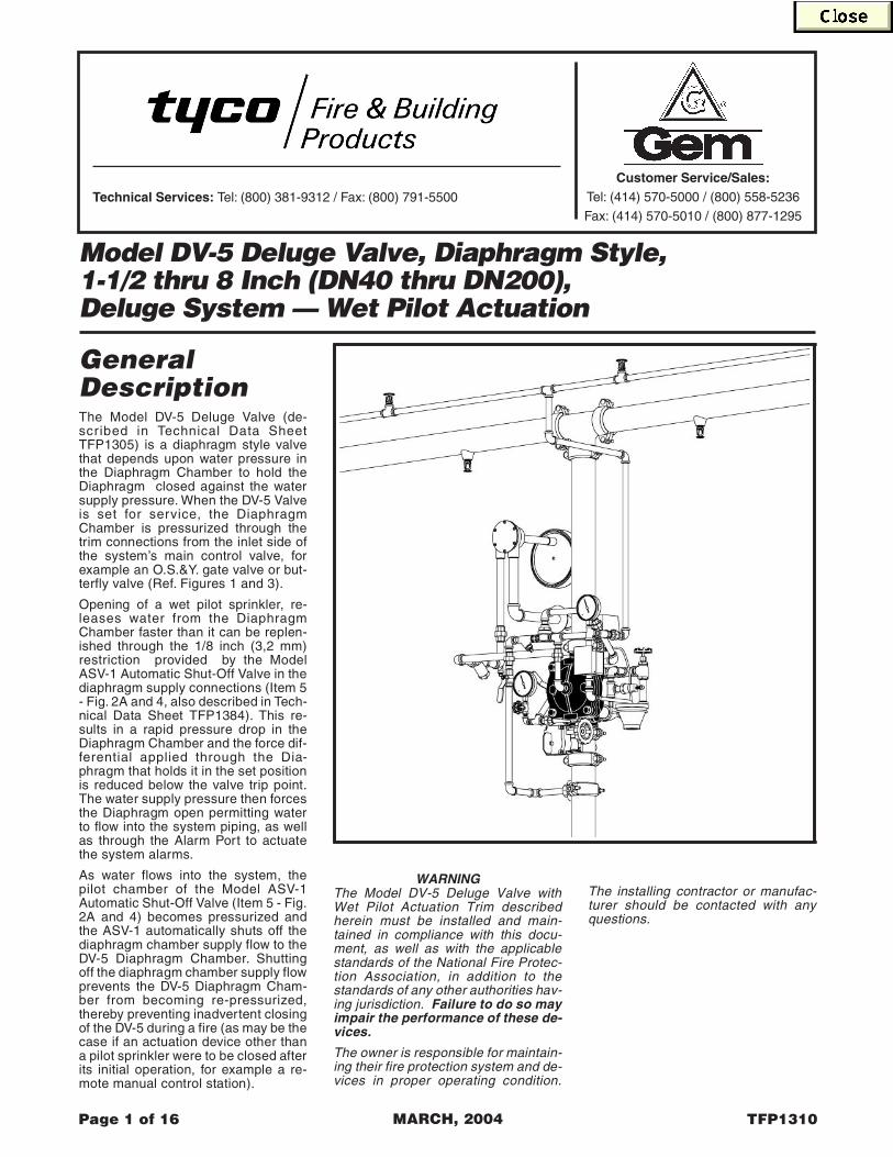
GeneralDescriptionThe Model DV-5 Deluge Valve (de-scribed in Technical Data SheetTFP1305) is a diaphragm style valvethat depends upon water pressure inthe Diaphragm Chamber to hold theDiaphragm closed against the watersupply pressure. When the DV-5 Valveis set for service, the DiaphragmChamber is pressurized through thetrim connections from the inlet side ofthe system’s main control valve, forexample an O.S.&Y. gate valve or but-terfly valve (Ref. Figures 1 and 3).
Opening of a wet pilot sprinkler, re-leases water from the DiaphragmChamber faster than it can be replen-ished through the 1/8 inch (3,2 mm)restriction provided by the ModelASV-1 Automatic Shut-Off Valve in thediaphragm supply connections (Item 5- Fig. 2A and 4, also described in Tech-nical Data Sheet TFP1384). This re-sults in a rapid pressure drop in theDiaphragm Chamber and the force dif-ferential applied through the Dia-phragm that holds it in the set positionis reduced below the valve trip point.The water supply pressure then forcesthe Diaphragm open permitting waterto flow into the system piping, as wellas through the Alarm Port to actuatethe system alarms.
As water flows into the system, thepilot chamber of the Model ASV-1Automatic Shut-Off Valve (Item 5 - Fig.2A and 4) becomes pressurized andthe ASV-1 automatically shuts off thediaphragm chamber supply flow to theDV-5 Diaphragm Chamber. Shuttingoff the diaphragm chamber supply flowprevents the DV-5 Diaphragm Cham-ber from becoming re-pressurized,thereby preventing inadvertent closingof the DV-5 during a fire (as may be thecase if an actuation device other thana pilot sprinkler were to be closed afterits initial operation, for example a re-mote manual control station).
WARNINGThe Model DV-5 Deluge Valve withWet Pilot Actuation Trim describedherein must be installed and main-tained in compliance with this docu-ment, as well as with the applicablestandards of the National Fire Protec-tion Association, in addition to thestandards of any other authorities hav-ing jurisdiction. Failure to do so mayimpair the performance of these de-vices.
The owner is responsible for maintain-ing their fire protection system and de-vices in proper operating condition.
The installing contractor or manufac-turer should be contacted with anyquestions.
Page 1 of 16 TFP1310MARCH, 2004
Model DV-5 Deluge Valve, Diaphragm Style,1-1/2 thru 8 Inch (DN40 thru DN200),Deluge System — Wet Pilot Actuation
Technical Services: Tel: (800) 381-9312 / Fax: (800) 791-5500
Customer Service/Sales:Tel: (414) 570-5000 / (800) 558-5236
Fax: (414) 570-5010 / (800) 877-1295

Page 2 of 16 TFP1310
FIGURE 1 — PART 1 OF 2SYSTEM SCHEMATIC (Front View) — WET PILOT ACTUATION
Page 3 of 16TFP1310
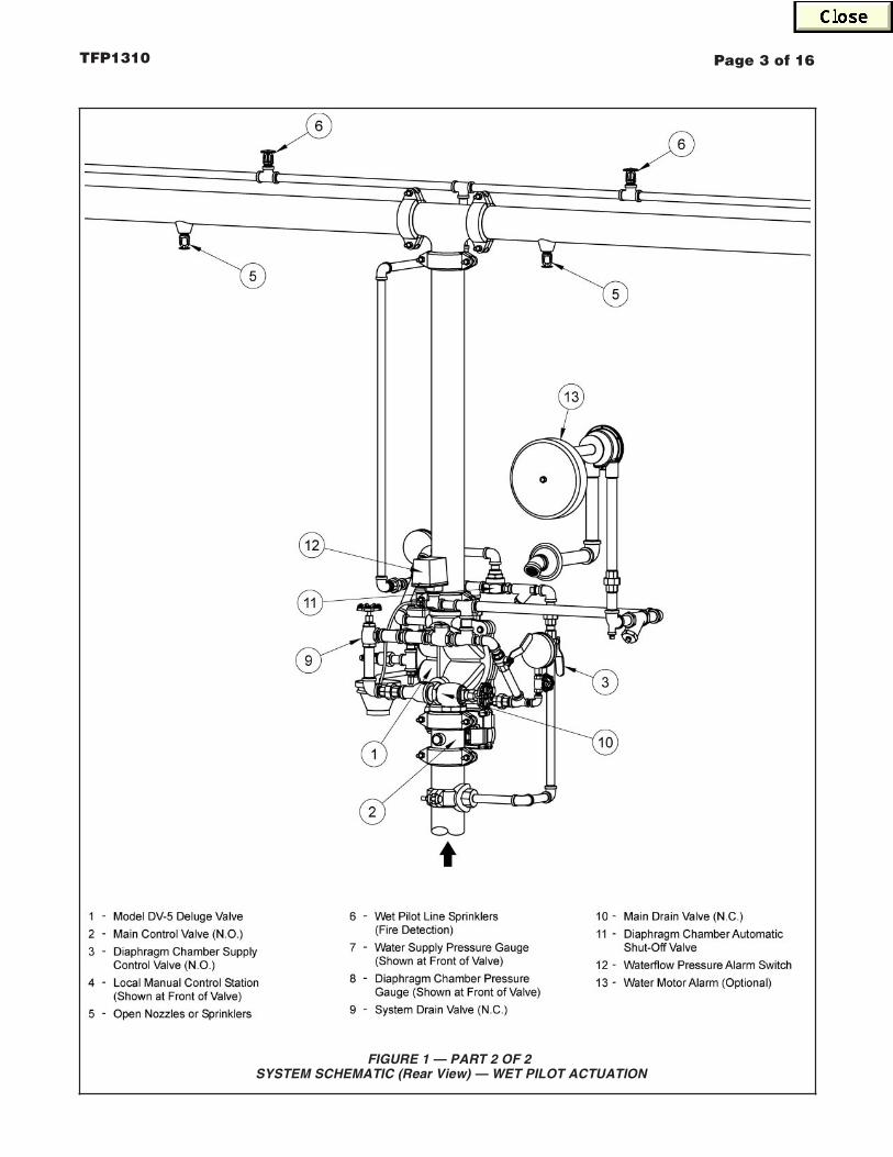
FIGURE 1 — PART 2 OF 2SYSTEM SCHEMATIC (Rear View) — WET PILOT ACTUATION

GeneralDescriptionThe Model DV-5 Deluge Valve (de-scribed in Technical Data SheetTFP1305) is a diaphragm style valvethat depends upon water pressure inthe Diaphragm Chamber to hold theDiaphragm closed against the watersupply pressure. When the DV-5 Valveis set for service, the DiaphragmChamber is pressurized through thetrim connections from the inlet side ofthe system’s main control valve, forexample an O.S.&Y. gate valve or but-terfly valve (Ref. Figures 1 and 3).
Opening of a dry pilot sprinkler, re-leases pneumatic pressure from thepilot line. In turn, the Dry Pilot Actuator(Item D3 - Fig. 2A and 4) opens andreleases water from the DiaphragmChamber faster than it can be replen-ished through the 1/8 inch (3,2 mm)restriction provided by the ModelASV-1 Automatic Shut-Off Valve in thediaphragm supply connections (Item 5- Fig. 2A and 4, also described in Tech-nical Data Sheet TFP1384). This re-sults in a rapid pressure drop in theDiaphragm Chamber and the force dif-ferential applied through the Dia-phragm that holds it in the set positionis reduced below the valve trip point.The water supply pressure then forcesthe Diaphragm open permitting waterto flow into the system piping, as wellas through the Alarm Port to actuatethe system alarms.
As water flows into the system, thepilot chamber of the Model ASV-1Automatic Shut-Off Valve (Item 5 - Fig.2A and 4) becomes pressurized andthe ASV-1 automatically shuts off thediaphragm chamber supply flow to theDV-5 Diaphragm Chamber. Shuttingoff the diaphragm chamber supply flowprevents the DV-5 Diaphragm Cham-ber from becoming re-pressurized,thereby preventing inadvertent closingof the DV-5 during a fire (as may be thecase if an actuation device other than
a pilot sprinkler were to be closed afterits initial operation, for example a re-mote manual control station).
WARNINGThe Model DV-5 Deluge Valve withDry Pilot Actuation Trim describedherein must be installed and main-tained in compliance with this docu-ment, as well as with the applicablestandards of the National Fire Protec-tion Association, in addition to thestandards of any other authorities hav-ing jurisdiction. Failure to do so may
impair the performance of these de-vices.
The owner is responsible for maintain-ing their fire protection system and de-vices in proper operating condition.The installing contractor or manufac-turer should be contacted with anyquestions.
Page 1 of 16 TFP1315MARCH, 2004
Model DV-5 Deluge Valve, Diaphragm Style,1-1/2 thru 8 Inch (DN40 thru DN200),Deluge System — Dry Pilot Actuation
Technical Services: Tel: (800) 381-9312 / Fax: (800) 791-5500
Customer Service/Sales:Tel: (414) 570-5000 / (800) 558-5236
Fax: (414) 570-5010 / (800) 877-1295

Page 2 of 16 TFP1315
FIGURE 1 — PART 1 OF 2SYSTEM SCHEMATIC (Front View) — DRY PILOT ACTUATION
Automatic Air/Nitrogen Supply16 -
Model DV-5 Deluge Valve
Main Control Valve (N.O.)2
-
-
Diaphragm Chamber Supply3 -
Local Manual Control Station4 -
Open Nozzles or Sprinklers5 -
Dry Pilot Line Sprinklers6 -
Water Supply Pressure Gauge7 -
Diaphragm Chamber Pressure8 -
Control Valve (N.O.)
13
7
3
1
2
4
8
Gauge
(Fire Detection)
System Drain Valve (N.C.)9 -
Main Drain Valve (N.C.)10 -
Diaphragm Chamber Automatic11 -
Waterflow Pressure Alarm Switch12 -
Water Motor Alarm (Optional)13 -
Dry Pilot Actuator14 -
Low Pressure Alarm Switch15 -
Shut-Off Valve
(Shown at Rear of Valve)
(Shown at Rear of Valve)
66
14
16
15
55
1
9
11

Page 3 of 16TFP1315
FIGURE 1 — PART 2 OF 2SYSTEM SCHEMATIC (Rear View) — DRY PILOT ACTUATION
Model DV-5 Deluge Valve
Main Control Valve (N.O.)
1
2
-
-
Diaphragm Chamber Supply3 -
Local Manual Control Station4 -
Open Nozzles or Sprinklers5 -
6 -
Water Supply Pressure Gauge7 -
Diaphragm Chamber Pressure8 -
Control Valve (N.O.) Gauge (Shown at Front of Valve)
System Drain Valve (N.C.)9 -
Main Drain Valve (N.C.)10 -
Diaphragm Chamber Automatic11 -
Waterflow Pressure Alarm Switch12 -
Water Motor Alarm (Optional)13 -
Dry Pilot Actuator14 -
Low Pressure Alarm Switch15 -
Shut-Off Valve
16 -
11
1
2
3
10
(Shown at Front of Valve)
13
(Shown at Front of Valve)
Dry Pilot Line Sprinklers(Fire Detection)
Automatic Air/Nitrogen Supply
16
14
12
15
66
55
9

GeneralDescriptionThe Model DV-5 Deluge Valve (de-scribed in Technical Data SheetTFP1305) is a diaphragm style valvethat depends upon water pressure inthe Diaphragm Chamber to hold theDiaphragm closed against the watersupply pressure. When the DV-5 Valveis set for service, the DiaphragmChamber is pressurized through thetrim connections from the inlet side ofthe system’s main control valve, forexample an O.S.&Y. gate valve or but-terfly valve (Ref. Figures 1 and 3).
Operation of an electrical device suchas a heat sensitive thermostat, smokedetector, or electrical manual controlstation signals the deluge valve releas-ing panel to energize the SolenoidValve. In turn, the energized SolenoidValve opens to release water from theDiaphragm Chamber faster than it canbe replenished through the 1/8 inch(3,2 mm) restriction provided by theModel ASV-1 Automatic Shut-OffValve in the diaphragm supply connec-tions (Item 5 - Fig. 2A and 4, alsodescribed in Technical Data SheetTFP1384). This results in a rapid pres-sure drop in the Diaphragm Chamberand the force differential appliedthrough the Diaphragm that holds it inthe set position is reduced below thevalve trip point. The water supply pres-sure then forces the Diaphragm openpermitting water to flow into the systempiping, as well as through the AlarmPort to actuate the system alarms.
As water flows into the system, thepilot chamber of the Model ASV-1Automatic Shut-Off Valve (Item 5 - Fig.2A and 4) becomes pressurized andthe ASV-1 automatically shuts off thediaphragm chamber supply flow to theDV-5 Diaphragm Chamber. Shuttingoff the diaphragm chamber supply flowprevents the DV-5 Diaphragm Cham-ber from becoming re-pressurized,thereby preventing inadvertent closing
of the DV-5 during a fire (as may be thecase should the Solenoid Valve be-come de-energized after its initial op-eration).
WARNINGThe Model DV-5 Deluge Valve withElectric Actuation Trim describedherein must be installed and main-tained in compliance with this docu-ment, as well as with the applicablestandards of the National Fire Protec-tion Association, in addition to thestandards of any other authorities hav-ing jurisdiction. Failure to do so may
impair the performance of these de-vices.
The owner is responsible for maintain-ing their fire protection system and de-vices in proper operating condition.The installing contractor or manufac-turer should be contacted with anyquestions.
Page 1 of 14 TFP1320MARCH, 2004
Model DV-5 Deluge Valve, Diaphragm Style,1-1/2 thru 8 Inch (DN40 thru DN200),Deluge System — Electric Actuation
Technical Services: Tel: (800) 381-9312 / Fax: (800) 791-5500
Customer Service/Sales:Tel: (414) 570-5000 / (800) 558-5236
Fax: (414) 570-5010 / (800) 877-1295

Page 2 of 14 TFP1320
FIGURE 1 — PART 1 OF 2SYSTEM SCHEMATIC (Front View) — ELECTRIC ACTUATION
Model DV-5 Deluge Valve
Main Control Valve (N.O.)
1
2
-
-
Diaphragm Chamber Supply3 -
Local Manual Control Station4 -
Open Nozzles or Sprinklers5 -
Heat Detectors, Smoke Detectors,6 -
Water Supply Pressure Gauge7 -
Diaphragm Chamber Pressure8 -
Control Valve (N.O.)
13
7
3
1
2
8
Gauge
etc. (Fire Detection)
15
System Drain Valve (N.C.)9 -
Main Drain Valve (N.C.)10 -
Diaphragm Chamber Automatic11 -
Waterflow Pressure Alarm Switch12 -
Water Motor Alarm (Optional)13 -
Solenoid Valve14 -
Deluge Valve Releasing Panel15 -
Shut-Off Valve
(Shown at Rear of Valve)
(Shown at Rear of Valve)
5
5
4
11
14
9
6

Page 3 of 14TFP1320
FIGURE 1 — PART 2 OF 2SYSTEM SCHEMATIC (Rear View) — ELECTRIC ACTUATION
Model DV-5 Deluge Valve
Main Control Valve (N.O.)
1
2
-
-
Diaphragm Chamber Supply3 -
Local Manual Control Station4 -
Open Nozzles or Sprinklers5 -
Heat Detectors, Smoke Detectors,6 -
Water Supply Pressure Gauge7 -
Diaphragm Chamber Pressure8 -
Control Valve (N.O.) Gauge (Shown at Front of Valve)
etc. (Fire Detection)
System Drain Valve (N.C.)9 -
Main Drain Valve (N.C.)10 -
Diaphragm Chamber Automatic11 -
Waterflow Pressure Alarm Switch12 -
Water Motor Alarm (Optional)13 -
Solenoid Valve14 -
Deluge Valve Releasing Panel15 -
Shut-Off Valve
1
2
3
10
12
14
15
(Shown at Front of Valve)
13
9
(Shown at Front of Valve)
55
11
6
Model DV-5 Deluge Valve with Remote-Resetting Trim 2 to 8 Inch (DN50 to DN200)
Page 1 of 24 JULY 2011 TFP1331
For more information, contact your local sales office or visit www.tycofsbp.com.
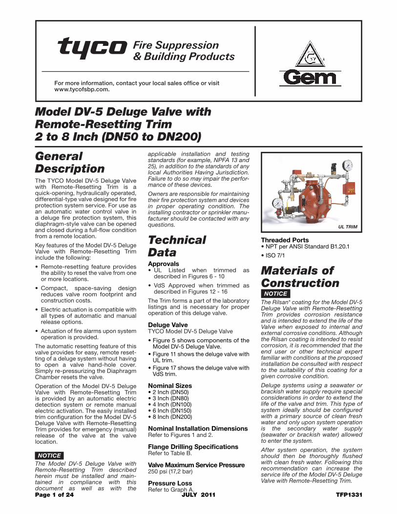
General DescriptionThe TYCO Model DV-5 Deluge Valve with Remote-Resetting Trim is a quick-opening, hydraulically operated, differential-type valve designed for fire protection system service. For use as an automatic water control valve in a deluge fire protection system, this diaphragm-style valve can be opened and closed during a full-flow condition from a remote location.
Key features of the Model DV-5 Deluge Valve with Remote-Resetting Trim include the following:
• Remote-resetting feature provides the ability to reset the valve from one or more locations.
• Compact, space-saving design reduces valve room footprint and construction costs.
• Electric actuation is compatible with all types of automatic and manual release options.
• Actuation of fire alarms upon system operation is provided.
The automatic resetting feature of this valve provides for easy, remote reset-ting of a deluge system without having to open a valve hand-hole cover. Simply re-pressurizing the Diaphragm Chamber resets the valve.
Operation of the Model DV-5 Deluge Valve with Remote-Resetting Trim is provided by an automatic electric detection sys tem or remote manual electric activation. The easily installed trim con figuration for the Model DV-5 Deluge Valve with Remote-Resetting Trim provides for emergency (manual) release of the valve at the valve location.
NOTICEThe Model DV-5 Deluge Valve with Remote-Resetting Trim described herein must be installed and main-tained in compliance with this document as well as with the
applicable installation and testing standards (for example, NPFA 13 and 25), in addition to the standards of any local Authorities Having Jurisdiction. Failure to do so may impair the perfor-mance of these devices.
Owners are responsible for maintaining their fire protection system and devices in proper operating condition. The installing contractor or sprinkler manu-facturer should be contacted with any questions.
Technical DataApprovals• UL Listed when trimmed as
described in Figures 6 - 10
• VdS Approved when trimmed as described in Figures 12 - 16
The Trim forms a part of the laboratory listings and is necessary for proper operation of this deluge valve.
Deluge ValveTYCO Model DV-5 Deluge Valve
•Figure 5 shows components of the Model DV-5 Deluge Valve.
•Figure 11 shows the deluge valve with UL trim.
•Figure 17 shows the deluge valve with VdS trim.
Nominal Sizes•2 Inch (DN50)•3 Inch (DN80)•4 Inch (DN100)•6 Inch (DN150) •8 Inch (DN200)
Nominal Installation Dimensions Refer to Figures 1 and 2.
Flange Drilling SpecificationsRefer to Table B.
Valve Maximum Service Pressure250 psi (17,2 bar)
Pressure LossRefer to Graph A.
Threaded Ports•NPT per ANSI Standard B1.20.1
•ISO 7/1
Materials of ConstructionNOTICE
The Rilsan* coating for the Model DV-5 Deluge Valve with Remote-Resetting Trim provides corrosion resistance and is intended to extend the life of the Valve when exposed to internal and external corrosive conditions. Al though the Rilsan coating is intended to resist corrosion, it is recommended that the end user or other technical expert familiar with conditions at the proposed installation be consulted with respect to the suitability of this coating for a given corrosive condition.
Deluge systems using a seawater or brackish water supply require special considerations in order to extend the life of the valve and trim. This type of system ideally should be configured with a primary source of clean fresh water and only upon system operation is the secondary water supply (seawater or brackish water) allowed to enter the system.
After system operation, the system should then be thoroughly flushed with clean fresh water. Follow ing this recommendation can increase the service life of the Model DV-5 Deluge Valve with Remote-Resetting Trim.
UL TRIM

TFP1331Page 2 of 24
Deluge Valve•Body and Hand-Hole Cover
RILSAN* coated ductile iron per ASTM A 536-77, Grade 65-45-12
•DiaphragmNylon fabric reinforced, natural rubber per ASTM D 2000
•V-Ring Applies only to 6 Inch/DN150 and 8 Inch/DN200
Natural rubber per ASTM D2000
•Diaphragm Cover FastenersGalvanized carbon steel
Vertical Valve Trim (Ordered Separately for the Americas)The Solenoid Valve and Waterflow Pressure Alarm Switch, provided as standard with only the VdS Trim, are for use in non-hazardous locations; that is, locations where potentially explosive atmospheres are not present. These parts are separately ordered for the UL Trim.
Design Criteria The following items must be consid-ered and applied accordingly for TYCO Model DV-5 Deluge Valve with Remote-Resetting Trim installations.
NOTICEResponsibility lies with owners to design into the system a releasing circuit such that a Solenoid Valve is properly configured to enable remote resetting.
The building owner must be informed of the capabilities and limitations of a remote-resetting system as it pertains to the possibility of an inadvertent manual closing of the Model DV-5 Deluge Valve during a fire condition. Therefore, personnel responsible for the fire protection system must be fully trained on system components and required actions in the case of an alarm.
The Control Panel, Detectors, and Pull Stations are to be installed in accor-dance with their laboratory listings and approval.
System piping is to be installed so that it is self-draining. TYCO Model AD-2 Automatic Drain Valves can be used to drain low sections of pipe as necessary. For more information, refer to technical data sheet TFP1632.
OperationThe TYCO Remote-Resetting System includes a differential valve that uses water pressure in the Diaphragm Chamber (Figures 3 and 4) to hold the Diaphragm closed against the water supply pressure.
When the Model DV-5 Valve with Remote-Resetting Trim is set for service, the Diaphragm Chamber is pressurized through the trim connec-tions from the inlet side of the system’s main control/shut-off valve, for example an O.S.&Y. gate valve or butterfly valve.
Opening of the Solenoid Valve in the Remote-Resetting Trim releases water from the Diaphragm Chamber faster than it can be replenished through the Restriction in the Diaphragm Chamber Supply Connection provided
in the trim. This release results in a rapid pressure drop in the Diaphragm Chamber, and the force differential applied through the Diaphragm that holds it in the set position is reduced below the valve trip point.
The water supply pressure then forces the Diaphragm open, permitting water to flow into the system piping, as well as through the Alarm Port to actuate system alarms.
Closing of the Solenoid Valve in the Remote-Resetting Trim permits the Diaphragm Chamber to repres-surize. This repressurizing results in a pressure increase in the Diaphragm Chamber. The resulting force repres-surizes the Diaphragm Chamber, closing the valve and stopping the flow of water into the system piping.
InstallationNOTICE
Proper operation of the Model DV-5 Deluge Valve with Remote-Resetting Trim depends upon trim installed in accordance with the instructions given in this technical data sheet. Failure to follow the appropriate trim diagram may prevent the valve from functioning properly, may void the manufactur-er’s warranty, and will void listings and approvals.
The Model DV-5 Deluge Valve and associated trim must be maintained at a minimum temperature of 40°F (4°C).
Heat tracing of the Model DV-5 Deluge Valve or its associated trim is not permitted. Heat tracing can result in the formation of hardened mineral deposits that are capable of preventing proper operation.
End Connection Nominal Valve Size in Pounds (kg.)
Inlet Outlet 2 Inch (DN50)
3 Inch (DN80)
4 Inch (DN100)
6 Inch (DN150)
8 Inch (DN200)
Thread Thread 12 lbs. (5,4 kg.) N/A N/A N/A N/A
Groove Groove 10 lbs. (4,5 kg.)
31 lbs. (14,1 kg.)
61 lbs. (27,7 kg.)
99 lbs. (44,9 kg.)
150 lbs. (68,1 kg.)
Flange Groove N/A 39 lbs. (17,7 kg.)
74 lbs. (33,6 kg.)
107 lbs. (48,5 kg.)
170 lbs. (77,8 kg.)
Flange Flange N/A 47 lbs. (21,3 kg.)
80 lbs. (36,3 kg.)
115 lbs. (52,3 kg.)
190 lbs. (87,5 kg.)
TABLE A MODEL DV-5 DELUGE VALVE WITH REMOTE-RESETTING TRIM
— AVAILABLE END CONNECTIONS AND WEIGHTS —
*RILSAN is a registered trademark of ATOFINA Chemicals, Inc. The Rilsan coating is a polyamide (Nylon 11) coating.
Model DV-5 Deluge Valve with Remote-Resetting, Pressure-Reducing Trim 4 Inch and 6 Inch (DN100 and DN150)
Page 1 of 10 JULY 2011 TFP1332
For more information, contact your local sales office or visit www.tycofsbp.com.
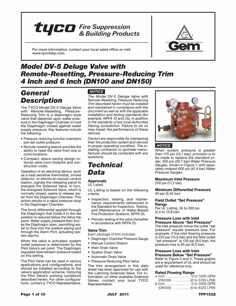
General DescriptionThe TYCO Model DV-5 Deluge Valve with Remote-Resetting, Pressure-Reducing Trim is a diaphragm-style valve that depends upon water pres-sure in the Diaphragm Chamber to hold the Diaphragm closed against water supply pressure. Key features include the following:
•Pressure-reducing function maintains pre-set outlet pressure.
•Remote-resetting feature provides the ability to reset the valve from one or more locations.
•Compact, space-saving design re-duces valve room footprint and con-struction costs.
Operation of an electrical device, such as a heat sensitive thermostat, smoke detector, or electrical manual control station, signals the releasing panel to energize the Solenoid Valve. In turn, the energized Solenoid Valve, which is normally closed, opens to release wa-ter from the Diaphragm Chamber. This action results in a rapid pressure drop in the Diaphragm Chamber.
The force differential applied through the Diaphragm that holds it in the set position is reduced below the Valve trip point. Water supply pressure then forc-es the Diaphragm open, permitting wa-ter to flow into the system piping and through the Alarm Port, actuating sys-tem alarms.
When the valve is activated, system outlet pressure is determined by the Pilot Valve’s set point. The Diaphragm regulates downstream pressure based on this setting.
The Pilot Valve can be used in various applications and configurations, and should be installed according to the valve’s application scheme, honoring the Pilot Valve’s working conditions described herein. For other configura-tions, contact a TYCO Representative.
NOTICEThe Model DV-5 Deluge Valve with Remote-Resetting, Pressure-Reducing Trim described herein must be installed and maintained in compliance with this document as well as with the applicable installation and testing standards (for example, NPFA 13 and 25), in addition to the standards of any local Authorities Having Jurisdiction. Failure to do so may impair the performance of these devices.
Owners are responsible for maintaining their fire protection system and devices in proper operating condition. The in-stalling contractor or sprinkler manu-facturer should be contacted with any questions.
Technical DataApprovalsUL Listed
UL Listing is based on the following criteria:
• Inspection, testing, and mainte-nance requirements referenced in the Standard for Inspection, Testing, and Maintenance of Water-Based Fire Protection Systems, NFPA 25.
• Periodic testing of the valve thereafter in accordance with NFPA 25.
Valve TrimEach package of trim includes: • Diaphragm Chamber Pressure Gauge• Manual Control Station• Main Drain Valve• System Drain Valve• Automatic Drain Valve• Pressure-Reducing Pilot ValveThe trim arrangement in this data sheet has been approved for use with the Latching Solenoid Valve. For in-formation on other available Solenoid Valves, contact your local TYCO Representative.
NOTICEWhen system pressure is greater than 175 psi (12,1 bar), provision is to be made to replace the standard-or-der, 300 psi (20,7 bar) Water Pressure Gauges, shown in Figure 1, with sepa-rately ordered 600 psi (41,4 bar) Water Pressure Gauges.
Maximum Inlet Pressure250 psi (17,2 bar)
Minimum Differential Pressure50 psi (3,45 bar)
Field Outlet “Set Pressure” RangePer UL Listing, 35 to 200 psi (2,4 to 13,8 bar)
Pressure Loss with Inlet Pressure Above “Set Pressure”The inlet pressure minus the outlet “set pressure” equals pressure loss. For example, if the inlet flowing pressure is 225 psi (15,5 bar) and the field outlet “set pressure” is 130 psi (9,0 bar), the pressure loss is 95 psi (6,5 bar).
Pressure Loss with Inlet Pressure Below “Set Pressure”Refer to Figure 3 and 4. These graphs are a requirement of UL and should be used for reference only.
Rated Flowing Range4 inch . . . . . . . . . . . . . 0 to 1000 GPM
(DN100) . . . . . . . . .(0 to 3785 LPM)6 inch . . . . . . . . . . . . . 0 to 2000 GPM
(DN150) . . . . . . . . (0 to 8325 LPM)
TFP1332Page 2 of 10
Pressure-Reducing Pilot ValveThe Pilot Valve operates when hydraulic pressure is applied below the spring-loaded membrane. The spring’s tension upon the membrane can be adjusted (increased by the Adjusting Screw). The membrane is connected to the Pilot Valve’s seal trim, opening and closing the Pilot Valve’s water passage.
The Pilot Valve is normally Open. When no pressure is applied below the spring-loaded membrane, the Pilot Valve allows the deluge valve to open. Once pipeline pressure is built down-stream of the deluge valve, this pres-sure is conveyed to the Pilot Valve’s membrane through the sensor port. When the pressure surpasses the set point (pre-adjusted through the Pilot Valve’s Adjusting Screw), the mem-brane moves upwards and water pas-sage ceases, closing the deluge Valve.
When the downstream pressure reduc-es below the Pilot Valve’s set point, the membrane moves downwards, opening the water passage, allowing the deluge valve to open.
The Pilot Valve is mounted with a prim-ing supply restriction between the Main Valve’s upstream and the Pilot Valve’s inlet. The valve is a 2-way pilot. During operation, water circulates constantly through the Pilot Valve, providing an immediate response to any changes in pipeline pressure.
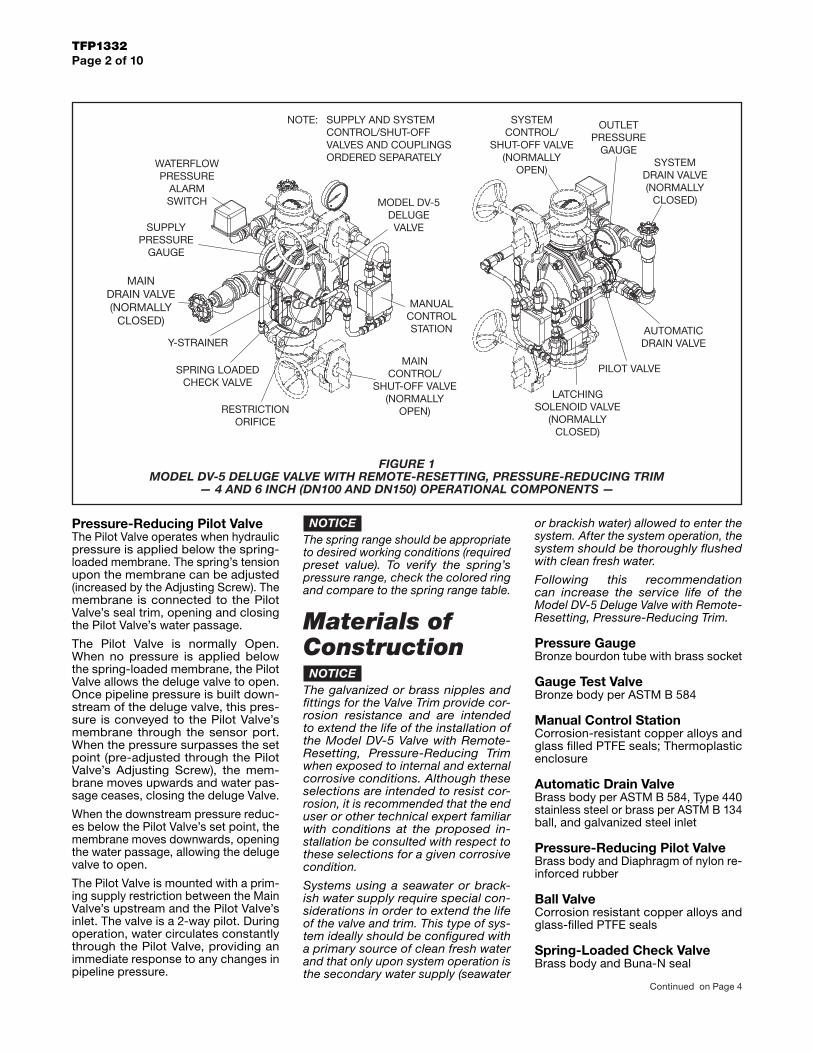
FIGURE 1 MODEL DV-5 DELUGE VALVE WITH REMOTE-RESETTING, PRESSURE-REDUCING TRIM
— 4 AND 6 INCH (DN100 AND DN150) OPERATIONAL COMPONENTS —
NOTICEThe spring range should be appropriate to desired working conditions (required preset value). To verify the spring’s pressure range, check the colored ring and compare to the spring range table.
Materials of ConstructionNOTICE
The galvanized or brass nipples and fittings for the Valve Trim provide cor-rosion resistance and are intended to extend the life of the installation of the Model DV-5 Valve with Remote-Resetting, Pressure-Reducing Trim when exposed to internal and external corrosive conditions. Although these selections are intended to resist cor-rosion, it is recommended that the end user or other technical expert familiar with conditions at the proposed in-stallation be consulted with respect to these selections for a given corrosive condition.
Systems using a seawater or brack-ish water supply require special con-siderations in order to extend the life of the valve and trim. This type of sys-tem ideally should be configured with a primary source of clean fresh water and that only upon system operation is the secondary water supply (seawater
or brackish water) allowed to enter the system. After the system operation, the system should be thoroughly flushed with clean fresh water.
Following this recommendation can increase the service life of the Model DV-5 Deluge Valve with Remote-Resetting, Pressure-Reducing Trim.
Pressure GaugeBronze bourdon tube with brass socket
Gauge Test ValveBronze body per ASTM B 584
Manual Control StationCorrosion-resistant copper alloys and glass filled PTFE seals; Thermoplastic enclosure
Automatic Drain ValveBrass body per ASTM B 584, Type 440 stainless steel or brass per ASTM B 134 ball, and galvanized steel inlet
Pressure-Reducing Pilot ValveBrass body and Diaphragm of nylon re-inforced rubber
Ball ValveCorrosion resistant copper alloys and glass-filled PTFE seals
Spring-Loaded Check ValveBrass body and Buna-N seal
OUTLETPRESSURE
GAUGE
AUTOMATICDRAIN VALVE
SYSTEMDRAIN VALVE(NORMALLY
CLOSED)
MANUALCONTROLSTATION
RESTRICTIONORIFICE
LATCHINGSOLENOID VALVE
(NORMALLYCLOSED)
Y-STRAINER
MODEL DV-5DELUGEVALVE
SPRING LOADEDCHECK VALVE
MAINCONTROL/
SHUT-OFF VALVE(NORMALLY
OPEN)
SYSTEMCONTROL/
SHUT-OFF VALVE(NORMALLY
OPEN)
PILOT VALVE
SUPPLY AND SYSTEMCONTROL/SHUT-OFFVALVES AND COUPLINGSORDERED SEPARATELY
NOTE:
WATERFLOWPRESSURE
ALARMSWITCH
SUPPLYPRESSURE
GAUGE
MAINDRAIN VALVE(NORMALLY
CLOSED)
Continued on Page 4

GeneralDescriptionThe Model DV-5 Supervised Single In-terlock Preaction System with Wet Pi-lot Actuation (Fig. 1) utilizes automaticsprinklers and a supplemental detec-tion system. The supplemental detec-tion system is comprised of wet pilotlines and pilot sprinklers. Actuation ofthe detection system automatically op-erates (releases) the Model DV-5 Del-uge Valve, allowing water to flow intothe sprinkler piping system and to bedischarged from any sprinklers thatmay be open.
In accordance with the requirementsof the National Fire Protection Asso-ciation, a preaction system employingmore than 20 automatic sprinklers is tohave the sprinkler piping automaticallysupervised to monitor the overall in-tegrity of the system. In the case of aSupervised Single Interlock PreactionSystem, a Riser Check Valve (thatdoes not require the use of primingwater) provides an air check so thatthe system can be automatically pres-surized with a nominal supervisory airor nitrogen pressure of 10 psi (0,69bar). A supervisory low pressure alarmswitch that is set to transfer its contactsat nominally 5 psi (0,34 bar), on de-creasing pressure, is utilized to indi-cate whether there are any abnormalleaks in the sprinkler system piping.Loss of air pressure from the systemas a result of a damaged sprinkler orbroken piping will not cause the DV-5Valve to open — the air pressure is forsupervisory alarm only.
Typically, the system designer selectsthe detection components for a singleinterlock preaction system that will re-spond to a fire sooner than the auto-matic sprinklers. Consequently, thesystem will experience a minimal delayin water delivery over that for a wetpipe sprinkler system because thesystem will have essentially filled withwater before a sprinkler operates. In
the case of wet pilot actuation, thesystem designer selects wet pilotsprinklers that will operate sooner thanthe automatic sprinklers chosen foruse on the sprinkler piping.
Supervised single interlock preactionsystems are generally used to protectareas where there is danger of seriouswater damage that might result fromdamaged automatic sprinklers or pip-ing. Typically, such areas include com-puter rooms, storage areas for valu-able artifacts, libraries, and archives.
Single interlock preaction systems are
also effectively used to protect proper-ties where a pre-alarm of a possiblefire condition may allow time for fireextinguishment by alternate suppres-sion means, prior to a sprinkler dis-charge. In the event the fire cannototherwise be extinguished, the preac-tion sprinkler system will then performas the primary fire protection system.
The Model DV-5 Deluge Valve (de-scribed in Technical Data SheetTFP1305) is a diaphragm style valvethat depends upon water pressure inthe Diaphragm Chamber to hold the
Page 1 of 16 TFP1410SEPTEMBER, 2004
Preaction System with Model DV-5 Deluge ValveSingle Interlock, Supervised — Wet Pilot Actuation1-1/2 thru 8 Inch (DN40 thru DN200)
Technical Services: Tel: (800) 381-9312 / Fax: (800) 791-5500
(TEXT CONTINUED ON PAGE 9)
Customer Service/Sales:Tel: (414) 570-5000 / (800) 558-5236
Fax: (414) 570-5010 / (800) 877-1295
Customer Service/Sales:Tel: (414) 570-5000 / (800) 558-5236
Fax: (414) 570-5010 / (800) 877-1295
Customer Service/Sales:Tel: (414) 570-5000 / (800) 558-5236
Fax: (414) 570-5010 / (800) 877-1295
Customer Service/Sales:Tel: (414) 570-5000 / (800) 558-5236
Fax: (414) 570-5010 / (800) 877-1295
Customer Service/Sales:Tel: (414) 570-5000 / (800) 558-5236
Fax: (414) 570-5010 / (800) 877-1295
Customer Service/Sales:Tel: (414) 570-5000 / (800) 558-5236
Fax: (414) 570-5010 / (800) 877-1295
Customer Service/Sales:Tel: (414) 570-5000 / (800) 558-5236
Fax: (414) 570-5010 / (800) 877-1295
Customer Service/Sales:Tel: (414) 570-5000 / (800) 558-5236
Fax: (414) 570-5010 / (800) 877-1295
Customer Service/Sales:Tel: (414) 570-5000 / (800) 558-5236
Fax: (414) 570-5010 / (800) 877-1295
Customer Service/Sales:Tel: (414) 570-5000 / (800) 558-5236
Fax: (414) 570-5010 / (800) 877-1295
Customer Service/Sales:Tel: (414) 570-5000 / (800) 558-5236
Fax: (414) 570-5010 / (800) 877-1295
Customer Service/Sales:Tel: (414) 570-5000 / (800) 558-5236
Fax: (414) 570-5010 / (800) 877-1295
Customer Service/Sales:Tel: (414) 570-5000 / (800) 558-5236
Fax: (414) 570-5010 / (800) 877-1295
Customer Service/Sales:Tel: (414) 570-5000 / (800) 558-5236
Fax: (414) 570-5010 / (800) 877-1295
Customer Service/Sales:Tel: (414) 570-5000 / (800) 558-5236
Fax: (414) 570-5010 / (800) 877-1295
Customer Service/Sales:Tel: (414) 570-5000 / (800) 558-5236
Fax: (414) 570-5010 / (800) 877-1295
Customer Service/Sales:Tel: (414) 570-5000 / (800) 558-5236
Fax: (414) 570-5010 / (800) 877-1295
Customer Service/Sales:Tel: (414) 570-5000 / (800) 558-5236
Fax: (414) 570-5010 / (800) 877-1295
Customer Service/Sales:Tel: (414) 570-5000 / (800) 558-5236
Fax: (414) 570-5010 / (800) 877-1295
Customer Service/Sales:Tel: (414) 570-5000 / (800) 558-5236
Fax: (414) 570-5010 / (800) 877-1295
Customer Service/Sales:Tel: (414) 570-5000 / (800) 558-5236
Fax: (414) 570-5010 / (800) 877-1295
Customer Service/Sales:Tel: (414) 570-5000 / (800) 558-5236
Fax: (414) 570-5010 / (800) 877-1295
Customer Service/Sales:Tel: (414) 570-5000 / (800) 558-5236
Fax: (414) 570-5010 / (800) 877-1295
Customer Service/Sales:Tel: (414) 570-5000 / (800) 558-5236
Fax: (414) 570-5010 / (800) 877-1295
Customer Service/Sales:Tel: (414) 570-5000 / (800) 558-5236
Fax: (414) 570-5010 / (800) 877-1295
Customer Service/Sales:Tel: (414) 570-5000 / (800) 558-5236
Fax: (414) 570-5010 / (800) 877-1295
Customer Service/Sales:Tel: (414) 570-5000 / (800) 558-5236
Fax: (414) 570-5010 / (800) 877-1295

Page 2 of 16 TFP1410

Page 3 of 16TFP1410

GeneralDescriptionThe Model DV-5 Supervised Single In-terlock Preaction System with Dry PilotActuation (Fig. 1) utilizes automaticsprinklers and a supplemental detec-tion system. The supplemental detec-tion system is comprised of dry pilotlines and pilot sprinklers. Actuation ofthe detection system automatically op-erates (releases) the Model DV-5 Del-uge Valve, allowing water to flow intothe sprinkler piping system and to bedischarged from any sprinklers thatmay be open.
In accordance with the requirementsof the National Fire Protection Asso-ciation, a preaction system employingmore than 20 automatic sprinklers is tohave the sprinkler piping automaticallysupervised to monitor the overall in-tegrity of the system. In the case of aSupervised Single Interlock PreactionSystem, a Riser Check Valve (thatdoes not require the use of primingwater) provides an air check so thatthe system can be automatically pres-surized with a nominal supervisory airor nitrogen pressure of 10 psi (0,69bar). A supervisory low pressure alarmswitch that is set to transfer its contactsat nominally 5 psi (0,34 bar), on de-creasing pressure, is utilized to indi-cate whether there are any abnormalleaks in the sprinkler system piping.Loss of air pressure from the systemas a result of a damaged sprinkler orbroken piping will not cause the DV-5Valve to open — the air pressure is forsupervisory alarm only.
Typically, the system designer selectsthe detection components for a singleinterlock preaction system that will re-spond to a fire sooner than the auto-matic sprinklers. Consequently, thesystem will experience a minimal delayin water delivery over that for a wetpipe sprinkler system because thesystem will have essentially filled withwater before a sprinkler operates. In
the case of dry pilot actuation, the sys-tem designer selects pilot sprinklersthat will operate sooner than the auto-matic sprinklers chosen for use on thesprinkler piping.
Supervised single interlock preactionsystems are generally used to protectareas where there is danger of seriouswater damage that might result fromdamaged automatic sprinklers or pip-ing. Typically, such areas include com-puter rooms, storage areas for valu-able artifacts, libraries, and archives.
Single interlock preaction systems are
also effectively used to protect proper-ties where a pre-alarm of a possiblefire condition may allow time for fireextinguishment by alternate suppres-sion means, prior to a sprinkler dis-charge. In the event the fire cannototherwise be extinguished, the preac-tion sprinkler system will then performas the primary fire protection system.
The Model DV-5 Deluge Valve (de-scribed in Technical Data SheetTFP1305) is a diaphragm style valvethat depends upon water pressure in
Page 1 of 16 TFP1415SEPTEMBER, 2004
Preaction System with Model DV-5 Deluge ValveSingle Interlock, Supervised — Dry Pilot Actuation1-1/2 thru 8 Inch (DN40 thru DN200)
Technical Services: Tel: (800) 381-9312 / Fax: (800) 791-5500
(TEXT CONTINUED ON PAGE 9)
Customer Service/Sales:Tel: (414) 570-5000 / (800) 558-5236
Fax: (414) 570-5010 / (800) 877-1295
Customer Service/Sales:Tel: (414) 570-5000 / (800) 558-5236
Fax: (414) 570-5010 / (800) 877-1295
Customer Service/Sales:Tel: (414) 570-5000 / (800) 558-5236
Fax: (414) 570-5010 / (800) 877-1295
Customer Service/Sales:Tel: (414) 570-5000 / (800) 558-5236
Fax: (414) 570-5010 / (800) 877-1295
Customer Service/Sales:Tel: (414) 570-5000 / (800) 558-5236
Fax: (414) 570-5010 / (800) 877-1295
Customer Service/Sales:Tel: (414) 570-5000 / (800) 558-5236
Fax: (414) 570-5010 / (800) 877-1295
Customer Service/Sales:Tel: (414) 570-5000 / (800) 558-5236
Fax: (414) 570-5010 / (800) 877-1295
Customer Service/Sales:Tel: (414) 570-5000 / (800) 558-5236
Fax: (414) 570-5010 / (800) 877-1295
Customer Service/Sales:Tel: (414) 570-5000 / (800) 558-5236
Fax: (414) 570-5010 / (800) 877-1295
Customer Service/Sales:Tel: (414) 570-5000 / (800) 558-5236
Fax: (414) 570-5010 / (800) 877-1295
Customer Service/Sales:Tel: (414) 570-5000 / (800) 558-5236
Fax: (414) 570-5010 / (800) 877-1295
Customer Service/Sales:Tel: (414) 570-5000 / (800) 558-5236
Fax: (414) 570-5010 / (800) 877-1295
Customer Service/Sales:Tel: (414) 570-5000 / (800) 558-5236
Fax: (414) 570-5010 / (800) 877-1295
Customer Service/Sales:Tel: (414) 570-5000 / (800) 558-5236
Fax: (414) 570-5010 / (800) 877-1295
Customer Service/Sales:Tel: (414) 570-5000 / (800) 558-5236
Fax: (414) 570-5010 / (800) 877-1295
Customer Service/Sales:Tel: (414) 570-5000 / (800) 558-5236
Fax: (414) 570-5010 / (800) 877-1295
Customer Service/Sales:Tel: (414) 570-5000 / (800) 558-5236
Fax: (414) 570-5010 / (800) 877-1295
Customer Service/Sales:Tel: (414) 570-5000 / (800) 558-5236
Fax: (414) 570-5010 / (800) 877-1295
Customer Service/Sales:Tel: (414) 570-5000 / (800) 558-5236
Fax: (414) 570-5010 / (800) 877-1295
Customer Service/Sales:Tel: (414) 570-5000 / (800) 558-5236
Fax: (414) 570-5010 / (800) 877-1295
Customer Service/Sales:Tel: (414) 570-5000 / (800) 558-5236
Fax: (414) 570-5010 / (800) 877-1295
Customer Service/Sales:Tel: (414) 570-5000 / (800) 558-5236
Fax: (414) 570-5010 / (800) 877-1295
Customer Service/Sales:Tel: (414) 570-5000 / (800) 558-5236
Fax: (414) 570-5010 / (800) 877-1295
Customer Service/Sales:Tel: (414) 570-5000 / (800) 558-5236
Fax: (414) 570-5010 / (800) 877-1295
Customer Service/Sales:Tel: (414) 570-5000 / (800) 558-5236
Fax: (414) 570-5010 / (800) 877-1295
Customer Service/Sales:Tel: (414) 570-5000 / (800) 558-5236
Fax: (414) 570-5010 / (800) 877-1295
Customer Service/Sales:Tel: (414) 570-5000 / (800) 558-5236
Fax: (414) 570-5010 / (800) 877-1295

Page 2 of 16 TFP1415

Page 3 of 16TFP1415

the Diaphragm Chamber to hold theDiaphragm closed against the watersupply pressure. When the DV-5 Valveis set for service, the DiaphragmChamber is pressurized through thetrim connections from the inlet side ofthe system’s main control valve, suchas an O.S.&Y. gate valve or butterflyvalve (Fig. 1).
Opening of a pilot sprinkler, releasespneumatic pressure from the pilot line.In turn, the Dry Pilot Actuator (Item D3- Fig. 2A) opens and releases waterfrom the Diaphragm Chamber fasterthan it can be replenished through the1/8 inch (3,2 mm) restriction providedby the Model ASV-1 Automatic Shut-Off Valve in the diaphragm supply con-nection (Item 5 - Fig. 2A, also de-scribed in Technical Data SheetTFP1384). This results in a rapid pres-sure drop in the Diaphragm Chamberto below the valve trip point. The watersupply pressure then forces the Dia-phragm open, permitting water to flowinto the system piping, as well asthrough the Alarm Port to actuate thesystem alarms
As water flows into the system, thepilot chamber of the Model ASV-1Automatic Shut-Off Valve (Item 5 - Fig.2A) becomes pressurized and theASV-1 automatically shuts off the dia-phragm chamber supply flow to theDV-5 Diaphragm Chamber. Shuttingoff the diaphragm chamber supply flowprevents the DV-5 Diaphragm Cham-ber from becoming re-pressurized,thereby preventing inadvertent closingof the DV-5 during a fire (as may be thecase if an actuation device other thana pilot sprinkler were to be closed afterits initial operation, for example a re-mote manual control station).
WARNINGThe Model DV-5 Supervised Single In-terlock Preaction System with Dry PilotActuation Trim described herein mustbe installed and maintained in compli-ance with this document, as well aswith the applicable standards of theNational Fire Protection Association,in addition to the standards of anyother authorities having jurisdiction.Failure to do so may impair the per-formance of the related devices.
The owner is responsible for maintain-ing their fire protection system and de-vices in proper operating condition.The installing contractor or manufac-turer should be contacted with anyquestions.
TechnicalDataApprovalsUL and C-UL Listed.
Deluge ValveModel DV-5.
Riser Check ValveModel CV-1FR.
NOTE1-1/2 inch (DN40) risers utilize a 2 inch(DN50) Riser Check Valve in combina-tion with the 1-1/2 inch (DN40) ModelDV-5 Deluge Valve.
Valve TrimThe Supervised Single Interlock Pre-action System With Dry Pilot ActuationTrim (Fig. 2A/2B) forms a part of thelaboratory listings and approvals. Thetrim is necessary for proper operationof the DV-5 Valve.
Each package of trim includes the fol-lowing items:
• Water Supply Pressure Gauge• Diaphragm Chamber
Pressure Gauge• Diaphragm Chamber Connections• Manual Control Station• Main Drain Valve• System Drain Valve• Alarm Test Valve• Automatic Drain Valve• System Air Pressure Gauge• Air Supply Connections• Low Air Pressure Supervisory
Switch• Waterflow Pressure Alarm Switch• Dry Pilot Actuator• Dry Pilot Line Pressure Gauge• Dry Pilot Line Low Pressure Alarm
Switch
To ease field assembly of the trim ar-rangement, the trim components areprovided par tially assembled asshown in Figure 2B.
The trim arrangement is provided withgalvanized or black nipples and fit-tings. The galvanized trim is intendedfor non-corrosive or corrosive condi-tions, whereas the black trim is princi-pally intended for use with AFFF sys-tems.
NOTEWhen the system pressure is greaterthan 175 psi (12,1 bar), provision is tobe made to replace the standard order300 psi (20,7 bar) Water PressureGauges, shown in Figure 2A/2B with
separately ordered 600 psi (41,4 bar)Water Pressure Gauges.
Detection SystemIn order for a single interlock preactionsystem to be hydraulically calculatedas a wet pipe system, as opposed to adry pipe sprinkler system, the detec-tion system must be designed to oper-ate sooner than the automatic sprin-klers on the sprinkler piping. In thecase of dry pilot actuation, the systemdesigner selects pilot sprinklers thatwill operate sooner than the automaticsprinklers chosen for use on the sprin-kler piping.
The Supervised Single Interlock Pre-action System With Dry Pilot ActuationTrim provides for connection of a de-tection system consisting of dry pilotline sprinklers (heat detectors) andmanual control stations intercon-nected with minimum 1/2 inch (DN15)Schedule 40 steel pipe. The pilot line,which is pressurized with air or nitro-gen, is connected to the “Dry Pilot De-tection” connection shown in Figure2B. Nominal installation dimensionsfor the Supervised Single InterlockPreaction System With Dry Pilot Ac-tuation Trim are shown in Figure 3.
Dry pilot line sprinklers are to be mini-mum 5.6 K-factor orifice listed or ap-proved automatic sprinklers. ManualControl Stations are to be the ModelMC-1 described in Technical DataSheet TFP1382.
The Dry Pilot Actuation Trim is pro-vided with a listed and approved ModelDP-1 Dry Pilot Actuator, which is de-scribed in Technical Data SheetTFP1380. The Actuator is rated for useat a maximum pilot service pressure of50 psi (3,4 bar) and a maximum watersupply service pressure of 250 psi(17,2 bar).
Graph A shows the “minimum pilot lineservice pressure” as a function of thewater supply pressure. The pressure inthe dry pilot actuation system must beautomatically maintained using one ofthe following maintenance devices, asappropriate.
• Model AMD-1 Air Maintenance De-vice (pressure reducing type), referto Technical Data Sheet TFP1221.
• Model AMD-2 Air Maintenance De-vice (compressor control type), referto Technical Data Sheet TFP1231.
• Model AMD-3 Nitrogen Mainte-nance Device (high pressure reduc-ing type), refer to Technical DataSheet TFP1241.
NOTESThe dew point of the pilot line air pres-sure must be maintained below the
Page 9 of 16TFP1415

GeneralDescriptionThe Model DV-5 Supervised Single In-terlock Preaction System with ElectricActuation (Fig. 1) utilizes automaticsprinklers and a supplemental detec-tion system. The supplemental detec-tion system is typically comprised of24 VDC heat detectors, smoke detec-tors, manual pull stations, etc. Actua-tion of the detection system automat-ically operates (releases) the ModelDV-5 Deluge Valve, allowing water toflow into the sprinkler piping systemand to be discharged from any sprin-klers that may be open.
In accordance with the requirementsof the National Fire Protection Asso-ciation, a preaction system employingmore than 20 automatic sprinklers is tohave the sprinkler piping automaticallysupervised to monitor the overall in-tegrity of the system. In the case of aSupervised Single Interlock PreactionSystem, a Riser Check Valve (thatdoes not require the use of primingwater) provides an air check so thatthe system can be automatically pres-surized with a nominal supervisory airor nitrogen pressure of 10 psi (0,69bar). A supervisory low pressure alarmswitch that is set to transfer its contactsat nominally 5 psi (0,34 bar), on de-creasing pressure, is utilized to indi-cate whether there are any abnormalleaks in the sprinkler system piping.Loss of air pressure from the systemas a result of a damaged sprinkler orbroken piping will not cause the DV-5Valve to open — the air pressure is forsupervisory alarm only.
Typically, the system designer selectsthe detection components for a singleinterlock preaction system that will re-spond to a fire sooner than the auto-matic sprinklers. Consequently, thesystem will experience a minimal delayin water delivery over that for a wetpipe sprinkler system because the
system will have begun to fill withwater before a sprinkler operates.
Supervised single interlock preactionsystems are generally used to protectareas where there is danger of seriouswater damage that might result fromdamaged automatic sprinklers or pip-ing. Typically, such areas include com-puter rooms, storage areas for valu-able artifacts, libraries, and archives.
Single interlock preaction systems arealso effectively used to protect proper-ties where a pre-alarm of a possiblefire condition may allow time for fire
extinguishment by alternate suppres-sion means, prior to a sprinkler dis-charge. In the event the fire cannototherwise be extinguished, the preac-tion sprinkler system will then performas the primary fire protection system.
The Model DV-5 Deluge Valve (de-scribed in Technical Data SheetTFP1305) is a diaphragm style valvethat depends upon water pressure inthe Diaphragm Chamber to hold theDiaphragm closed against the watersupply pressure. When the DV-5 Valveis set for service, the Diaphragm
Page 1 of 14 TFP1420SEPTEMBER, 2004
Preaction System with Model DV-5 Deluge ValveSingle Interlock, Supervised — Electric Actuation1-1/2 thru 8 Inch (DN40 thru DN200)
Technical Services: Tel: (800) 381-9312 / Fax: (800) 791-5500
(TEXT CONTINUED ON PAGE 9)
Customer Service/Sales:Tel: (414) 570-5000 / (800) 558-5236
Fax: (414) 570-5010 / (800) 877-1295
Customer Service/Sales:Tel: (414) 570-5000 / (800) 558-5236
Fax: (414) 570-5010 / (800) 877-1295
Customer Service/Sales:Tel: (414) 570-5000 / (800) 558-5236
Fax: (414) 570-5010 / (800) 877-1295
Customer Service/Sales:Tel: (414) 570-5000 / (800) 558-5236
Fax: (414) 570-5010 / (800) 877-1295
Customer Service/Sales:Tel: (414) 570-5000 / (800) 558-5236
Fax: (414) 570-5010 / (800) 877-1295
Customer Service/Sales:Tel: (414) 570-5000 / (800) 558-5236
Fax: (414) 570-5010 / (800) 877-1295
Customer Service/Sales:Tel: (414) 570-5000 / (800) 558-5236
Fax: (414) 570-5010 / (800) 877-1295
Customer Service/Sales:Tel: (414) 570-5000 / (800) 558-5236
Fax: (414) 570-5010 / (800) 877-1295
Customer Service/Sales:Tel: (414) 570-5000 / (800) 558-5236
Fax: (414) 570-5010 / (800) 877-1295
Customer Service/Sales:Tel: (414) 570-5000 / (800) 558-5236
Fax: (414) 570-5010 / (800) 877-1295
Customer Service/Sales:Tel: (414) 570-5000 / (800) 558-5236
Fax: (414) 570-5010 / (800) 877-1295
Customer Service/Sales:Tel: (414) 570-5000 / (800) 558-5236
Fax: (414) 570-5010 / (800) 877-1295
Customer Service/Sales:Tel: (414) 570-5000 / (800) 558-5236
Fax: (414) 570-5010 / (800) 877-1295
Customer Service/Sales:Tel: (414) 570-5000 / (800) 558-5236
Fax: (414) 570-5010 / (800) 877-1295
Customer Service/Sales:Tel: (414) 570-5000 / (800) 558-5236
Fax: (414) 570-5010 / (800) 877-1295
Customer Service/Sales:Tel: (414) 570-5000 / (800) 558-5236
Fax: (414) 570-5010 / (800) 877-1295
Customer Service/Sales:Tel: (414) 570-5000 / (800) 558-5236
Fax: (414) 570-5010 / (800) 877-1295
Customer Service/Sales:Tel: (414) 570-5000 / (800) 558-5236
Fax: (414) 570-5010 / (800) 877-1295
Customer Service/Sales:Tel: (414) 570-5000 / (800) 558-5236
Fax: (414) 570-5010 / (800) 877-1295
Customer Service/Sales:Tel: (414) 570-5000 / (800) 558-5236
Fax: (414) 570-5010 / (800) 877-1295
Customer Service/Sales:Tel: (414) 570-5000 / (800) 558-5236
Fax: (414) 570-5010 / (800) 877-1295
Customer Service/Sales:Tel: (414) 570-5000 / (800) 558-5236
Fax: (414) 570-5010 / (800) 877-1295
Customer Service/Sales:Tel: (414) 570-5000 / (800) 558-5236
Fax: (414) 570-5010 / (800) 877-1295
Customer Service/Sales:Tel: (414) 570-5000 / (800) 558-5236
Fax: (414) 570-5010 / (800) 877-1295
Customer Service/Sales:Tel: (414) 570-5000 / (800) 558-5236
Fax: (414) 570-5010 / (800) 877-1295
Customer Service/Sales:Tel: (414) 570-5000 / (800) 558-5236
Fax: (414) 570-5010 / (800) 877-1295
Customer Service/Sales:Tel: (414) 570-5000 / (800) 558-5236
Fax: (414) 570-5010 / (800) 877-1295

Page 2 of 14 TFP1420

Page 3 of 14TFP1420

Chamber is pressurized through thetrim connections from the inlet side ofthe system’s main control valve, suchas an O.S.&Y. gate valve or butterflyvalve (Fig. 1).
Operation of an electrical detection de-vice such as a heat sensitive thermo-stat, smoke detector, or electrical man-ual control station signals the delugevalve releasing panel to energize theSolenoid Valve. In turn, the energizedSolenoid Valve opens to release waterfrom the Diaphragm Chamber fasterthan it can be replenished through the1/8 inch (3,2 mm) restriction providedby the Model ASV-1 Automatic Shut-Off Valve in the diaphragm supply con-nection (Item 5 - Fig. 2A, also de-scribed in Technical Data SheetTFP1384). This results in a rapid pres-sure drop in the Diaphragm Chamberto below the valve trip point. The watersupply pressure then forces the Dia-phragm open, permitting water to flowinto the system piping, as well asthrough the Alarm Port to actuate thesystem alarms.
As water flows into the system, thepilot chamber of the Model ASV-1Automatic Shut-Off Valve (Item 5 - Fig.2A) becomes pressurized and theASV-1 automatically shuts off the dia-phragm chamber supply flow to theDV-5 Diaphragm Chamber. Shuttingoff the diaphragm chamber supply flowprevents the DV-5 Diaphragm Cham-ber from becoming re-pressurized,thereby preventing inadvertent closingof the DV-5 during a fire (as may be thecase should the Solenoid Valve be-come de-energized after its initial op-eration).
WARNINGThe Model DV-5 Supervised Single In-terlock Preaction System with ElectricActuation Trim described herein mustbe installed and maintained in compli-ance with this document, as well aswith the applicable standards of theNational Fire Protection Association,in addition to the standards of anyother authorities having jurisdiction.Failure to do so may impair the per-formance of the related devices.
The owner is responsible for maintain-ing their fire protection system and de-vices in proper operating condition.The installing contractor or manufac-turer should be contacted with anyquestions.
TechnicalDataApprovalsUL and C-UL Listed. FM Approved.
Deluge ValveModel DV-5.
Riser Check ValveModel CV-1FR.
NOTE1-1/2 inch (DN40) risers utilize a 2 inch(DN50) Riser Check valve in combina-tion with the 1-1/2 inch (DN40) ModelDV-5 Deluge Valve.
Valve TrimThe Supervised Single Interlock Pre-action System With Electric ActuationTrim (Fig. 2A/2B) forms a part of thelaboratory listings and approvals. Thetrim is necessary for proper operationof the DV-5 Valve.
Each package of trim includes the fol-lowing items:
• Water Supply Pressure Gauge• Diaphragm Chamber
Pressure Gauge• Diaphragm Chamber Connections• Manual Control Station• Main Drain Valve• System Drain Valve• Alarm Test Valve• Automatic Drain Valve• System Air Pressure Gauge• Air Supply Connections• Low Air Pressure Supervisory
Switch• Waterflow Pressure Alarm Switch
To ease field assembly of the trim ar-rangement, the trim components areprovided par tially assembled asshown in Figure 2B.
The trim arrangement is provided withgalvanized or black nipples and fit-tings. The galvanized trim is intendedfor non-corrosive or corrosive condi-tions, whereas the black trim is princi-pally intended for use with AFFF sys-tems.
NOTEWhen the system pressure is greaterthan 175 psi (12,1 bar), provision is tobe made to replace the standard order300 psi (20,7 bar) Water PressureGauges, shown in Figure 2A/2B withseparately ordered 600 psi (41,4 bar)Water Pressure Gauges.
Detection SystemIn order for a single interlock preaction
system to be hydraulically calculatedas a wet pipe system, as opposed to adry pipe sprinkler system, the detec-tion system must be designed to oper-ate sooner than the automatic sprin-klers on the sprinkler piping.
The Supervised Single Interlock Pre-action System With Electric ActuationTrim provides for electric operation ofthe DV-5 Valve by a detection systemconsisting of electrical devices such asheat sensitive thermostats, smoke de-tectors, and/or electric manual pull sta-tions. Information on the various typesof separately ordered Solenoid Valvesthat may be used with this trim pack-age is given in Technical Data SheetTFP2180. Nominal installation dimen-sions for the Supervised Single Inter-lock Preaction System With ElectricActuation Trim are shown in Figure 3.
NOTESApproval by Factory Mutual is contin-gent on the use of an FM Approved24VDC Solenoid Valve (P/N 52-287-1-024 or P/N 52-287-1-124). FM onlyapproves solenoid valves for use innon-hazardous locations.
Consult with the Authority Having Ju-risdiction regarding installation criteriapertaining to electric actuation cir-cuitry.
The Supervised Single Interlock Pre-action System With Electric ActuationTrim is provided with a Model ASV-1Automatic Shut-Off Valve (Item 5 - Fig.2A); consequently, the release circuitof the releasing panel need only pro-vide the standard ten minutes of alarmcondition intended to energize the So-lenoid Valve. After the ten minute du-ration, should the Solenoid Valve be-come de-energized and close(especially while operating under bat-tery back-up), the Automatic Shut-OffValve will have already automaticallyclosed thereby preventing the DV-5Diaphragm Chamber from becomingre-pressurized and preventing an in-advertent closing of the DV-5 during afire event.
System Air Pressure RequirementsThe supervisory air (nitrogen) pres-sure is to be 10 plus or minus 2 psi(0,69 plus or minus 0,07 bar). The useof a higher supervisory pressure issubject to approval by the AuthorityHaving Jurisdiction, and it should beunderstood that the use of a highersupervisory pressure may increasewater delivery time. The use of a lowersupervisory pressure may preventclearing the alarm of the SupervisoryLow Pressure Alarm Switch (Item P3 -Fig. 2A), which is factory set to alarmat 5 plus or minus 1 psi (0,34 plus orminus 0,07 bar) on decreasing pres-
Page 9 of 14TFP1420

Page 10 of 14 TFP1420
200 400 1000 3000200060010050
FLOW RATE IN GALLONS PER MINUTE (GPM)
3.0
NO
MIN
AL
PR
ES
SU
RE
DR
OP
IN P
OU
ND
S P
ER
SQ
UA
RE
INC
H(P
SI)
0.8
0.4
0.5
0.6
0.7
1.00.9
2.0
6.0
4.0
5.0
9.0
7.0
8.0
10.0
15.0
FLOW RATE IN LITRES PER MINUTE (LPM)
200 1000600400
(1 GPM = 3,785 LPM)
2000 70003000 5000 10000
(1P
SI=
0,06
895
BA
R)
NO
MIN
AL
PR
ES
SU
RE
DR
OP
IN B
AR
0,040
0,030
0,050
0,080
0,060
0,070
0,0900,100
0,200
0,800
0,400
0,300
0,600
0,500
0,700
1,0000,900
2 IN
CH
(DN
50)
1-1/
2IN
CH
(DN
40)
6 IN
CH
(DN
150)
4 IN
CH
(DN
100)
3 IN
CH
(DN
80)
8 IN
CH
(DN
200)
GRAPH ADELUGE AND CHECK VALVE COMBINATION*
— NOMINAL PRESSURE LOSS VERSUS FLOW —
* Model DV-5 Deluge Valve combined with Model CV-1FR Riser Check Valve
**1-1/2 inch Model DV-5 Deluge Valve combined with 2 inch Model CV-1FR Riser Check Valve
The approximate friction loss, based on the Hazen and Williams formula and expressed in equivalent length of pipe with C=120, is asfollows:
15 feet of 1-1/2 Sch. 40 pipe for the 1-1/2 inch Valve Combination** calculated on a typical flow rate of 100 GPM.28 feet of 2 inch Sch. 40 pipe for the 2 inch Valve Combination* calculated on a typical flow rate of 175 GPM.37 feet of 3 inch Sch. 40 pipe for the 3 inch Valve Combination* calculated on a typical flow rate of 350 GPM.48 feet of 4 inch Sch. 40 pipe for the 4 inch Valve Combination* calculated on a typical flow rate of 600 GPM.73 feet of 6 inch Sch. 40 pipe for the 6 inch Valve Combination* calculated on a typical flow rate of 1500 GPM.103 feet of 8 inch Sch. 40 pipe for the 8 inch Valve Combination* calculated on a typical flow rate of 2500 GPM.

GeneralDescriptionThe Model DV-5 Double Interlock Pre-action System with Electric/PneumaticActuation (Fig. 1) is designed for usein applications, such as refrigeratedareas, requiring the maximum degreeof protection against inadvertent flood-ing of the sprinkler system piping.
The Model DV-5 Double Interlock Pre-action System with Electric/PneumaticActuation utilizes a Model DV-5 DelugeValve and a Riser Check Valve. TheRiser Check Valve (that does not re-quire the use of priming water) isolatesthe Deluge Valve from the system airpressure. The releasing trim for theDeluge Valve utilizes a Solenoid Valveand a Dry Pilot Actuator in a seriesconfiguration. The system air pressureholds the Dry Plot Actuator closed,whereas the Solenoid Valve remainsclosed until it is electrically energizedby a Deluge Valve Releasing Panel(automatic control unit). The Releas-ing Panel is operated by either a firedetection device or manual electricpull station.
In order for the Double Interlock Pre-action System to automatically actu-ate, two independent events must oc-cur. The deluge valve releasing panelmust operate and open the SolenoidValve upon automatic operation of theelectric fire detection initiating circuitor manual operation of the electric-manual pull initiating circuit, and thesprinkler system piping must lose airpressure due to operation of one ormore sprinklers.
The Double Interlock Preaction Sys-tem will automatically actuate onlywhen both the Dry Pilot Actuator andthe Solenoid Valve are open at thesame time. Accidental opening of justthe Dry Pilot Actuator (for example: alift truck accidentally dislodges a sprin-kler), or just energizing the SolenoidValve (for example: an accidental op-
eration of an electric pull station), willonly cause an alarm, and will not actu-ate the system or flood the sprinklersystem piping.
The Model DV-5 Deluge Valve (de-scribed in Technical Data SheetTFP1305) is a diaphragm style valvethat depends upon water pressure inthe Diaphragm Chamber to hold theDiaphragm closed against the watersupply pressure. When the DV-5 Valveis set for service, the DiaphragmChamber is pressurized through thetrim connections from the inlet side ofthe system’s main control valve, for
example an O.S.&Y. gate valve or but-terfly valve (Fig. 1).
Operation of the Solenoid Valve andDry Pilot Actuator at the same timereleases water from the DiaphragmChamber faster than it can be replen-ished through the 1/8 inch (3,2 mm)Priming Supply Restriction (Item 7 -Fig. 2A) in the diaphragm supply con-nections. This results in a rapid pres-sure drop in the Diaphragm Chamberbelow the valve trip point. The watersupply pressure then forces the Dia-phragm open permitting water to flow
Page 1 of 16 TFP1460MARCH, 2005
Preaction System with Model DV-5 Deluge ValveDouble Interlock — Electric/Pneumatic Actuation1-1/2 thru 8 Inch (DN40 and DN200)
Technical Services: Tel: (800) 381-9312 / Fax: (800) 791-5500
(TEXT CONTINUED ON PAGE 9)
Customer Service/Sales:Tel: (414) 570-5000 / (800) 558-5236
Fax: (414) 570-5010 / (800) 877-1295
Customer Service/Sales:Tel: (414) 570-5000 / (800) 558-5236
Fax: (414) 570-5010 / (800) 877-1295
Customer Service/Sales:Tel: (414) 570-5000 / (800) 558-5236
Fax: (414) 570-5010 / (800) 877-1295
Customer Service/Sales:Tel: (414) 570-5000 / (800) 558-5236
Fax: (414) 570-5010 / (800) 877-1295
Customer Service/Sales:Tel: (414) 570-5000 / (800) 558-5236
Fax: (414) 570-5010 / (800) 877-1295
Customer Service/Sales:Tel: (414) 570-5000 / (800) 558-5236
Fax: (414) 570-5010 / (800) 877-1295
Customer Service/Sales:Tel: (414) 570-5000 / (800) 558-5236
Fax: (414) 570-5010 / (800) 877-1295
Customer Service/Sales:Tel: (414) 570-5000 / (800) 558-5236
Fax: (414) 570-5010 / (800) 877-1295
Customer Service/Sales:Tel: (414) 570-5000 / (800) 558-5236
Fax: (414) 570-5010 / (800) 877-1295
Customer Service/Sales:Tel: (414) 570-5000 / (800) 558-5236
Fax: (414) 570-5010 / (800) 877-1295
Customer Service/Sales:Tel: (414) 570-5000 / (800) 558-5236
Fax: (414) 570-5010 / (800) 877-1295
Customer Service/Sales:Tel: (414) 570-5000 / (800) 558-5236
Fax: (414) 570-5010 / (800) 877-1295
Customer Service/Sales:Tel: (414) 570-5000 / (800) 558-5236
Fax: (414) 570-5010 / (800) 877-1295
Customer Service/Sales:Tel: (414) 570-5000 / (800) 558-5236
Fax: (414) 570-5010 / (800) 877-1295
Customer Service/Sales:Tel: (414) 570-5000 / (800) 558-5236
Fax: (414) 570-5010 / (800) 877-1295
Customer Service/Sales:Tel: (414) 570-5000 / (800) 558-5236
Fax: (414) 570-5010 / (800) 877-1295
Customer Service/Sales:Tel: (414) 570-5000 / (800) 558-5236
Fax: (414) 570-5010 / (800) 877-1295
Customer Service/Sales:Tel: (414) 570-5000 / (800) 558-5236
Fax: (414) 570-5010 / (800) 877-1295
Customer Service/Sales:Tel: (414) 570-5000 / (800) 558-5236
Fax: (414) 570-5010 / (800) 877-1295
Customer Service/Sales:Tel: (414) 570-5000 / (800) 558-5236
Fax: (414) 570-5010 / (800) 877-1295
Customer Service/Sales:Tel: (414) 570-5000 / (800) 558-5236
Fax: (414) 570-5010 / (800) 877-1295
Customer Service/Sales:Tel: (414) 570-5000 / (800) 558-5236
Fax: (414) 570-5010 / (800) 877-1295
Customer Service/Sales:Tel: (414) 570-5000 / (800) 558-5236
Fax: (414) 570-5010 / (800) 877-1295
Customer Service/Sales:Tel: (414) 570-5000 / (800) 558-5236
Fax: (414) 570-5010 / (800) 877-1295
Customer Service/Sales:Tel: (414) 570-5000 / (800) 558-5236
Fax: (414) 570-5010 / (800) 877-1295
Customer Service/Sales:Tel: (414) 570-5000 / (800) 558-5236
Fax: (414) 570-5010 / (800) 877-1295
Customer Service/Sales:Tel: (414) 570-5000 / (800) 558-5236
Fax: (414) 570-5010 / (800) 877-1295
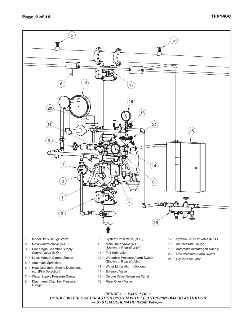
Page 2 of 16 TFP1460
FIGURE 1 — PART 1 OF 2DOUBLE INTERLOCK PREACTION SYSTEM WITH ELECTRIC/PNEUMATIC ACTUATION
— SYSTEM SCHEMATIC (Front View)—
Model DV-5 Deluge Valve
Main Control Valve (N.O.)
1
2
-
-
Diaphragm Chamber Supply3 -
Local Manual Control Station4 -
Automatic Sprinklers5 -
Heat Detectors, Smoke Detectors,6 -
Water Supply Pressure Gauge7 -
Diaphragm Chamber Pressure8 -
Control Valve (N.O.)
13
7
3
1
2
4
11 21
Gauge
etc. (Fire Detection)
14
5
15
System Drain Valve (N.C.)9 -
Main Drain Valve (N.C.)10 -
Fail-Safe Valve11 -
Waterflow Pressure Alarm Switch12 -
Water Motor Alarm (Optional)13 -
Solenoid Valve14 -
Deluge Valve Releasing Panel15 -
(Shown at Rear of Valve)
(Shown at Rear of Valve)
Riser Check Valve16 -
System Shut-Off Valve (N.O.)17 -
Air Pressure Gauge18 -
Automatic Air/Nitrogen Supply19 -
Low Pressure Alarm Switch20 -
5
17
19
9
20
18
16
Dry Pilot Actuator21 -
8
6

Page 3 of 16TFP1460
FIGURE 1 — PART 2 OF 2DOUBLE INTERLOCK PREACTION SYSTEM WITH ELECTRIC/PNEUMATIC ACTUATION
— SYSTEM SCHEMATIC (Rear View)—
Model DV-5 Deluge Valve
Main Control Valve (N.O.)
1
2
-
-
Diaphragm Chamber Supply3 -
Local Manual Control Station4 -
Automatic Sprinklers5 -
Heat Detectors, Smoke Detectors,6 -
Water Supply Pressure Gauge7 -
Diaphragm Chamber Pressure8 -
Control Valve (N.O.) Gauge (Shown at Front of Valve)
etc. (Fire Detection)
System Drain Valve (N.C.)9 -
Main Drain Valve (N.C.)10 -
Fail-Safe Valve11 -
Waterflow Pressure Alarm Switch12 -
Water Motor Alarm (Optional)13 -
Solenoid Valve14 -
Deluge Valve Releasing Panel15 -
(Shown at Front of Valve)
Riser Check Valve16 -
System Shut-Off Valve (N.O.)17 -
Air Pressure Gauge18 -
Automatic Air/Nitrogen Supply19 -
Low Pressure Alarm Switch20 -
1
2
10
12
6
15
55
(Shown at Front of Valve)
19
1320 17
9
(Shown at Front of Valve)
(Shown at Front of Valve)
Dry Pilot Actuator21 -
16
14
21
(Shown at Front of Valve)

Page 8 of 16 TFP1460
FIGURE 31-1/2 thru 8 INCH (DN40 thru DN200) MODEL DV-5 DELUGE VALVES
DOUBLE INTERLOCK PREACTION SYSTEM WITH ELECTRIC/PNEUMATIC ACTUATION TRIM— NOMINAL INSTALLATION DIMENSIONS —
(698,5)27.50
(689,0)27.13
(787,4)31.00
MINIMUM CLEARANCE.*
(254,0)10.00
(289,0)11.38
(298,5)11.75
(363,5)14.31
(266,7)10.50
(165,1)6.50
(200,0)7.88
(217,5)8.56
(252,4)9.94
(181,0)7.13
(9,5)0.38
(39,7)1.56
(644,5)25.38
(752,5)29.63
(44,5)1.75
(88,9)3.50
(266,7)10.50
(181,0)7.13
(231,8)9.13
(266,7)10.50
(152,4)6.00
(152,4)6.00
(390,5)15.38
(DN50)2"
(79,4)3.13
(177,8)7.00
(225,4)8.88
(266,7)10.50
(147,6)5.81
(147,6)5.81
(76,2)3.00
(101,6)4.00
(376,2)14.81
(DN40)1-1/2"
(101,6)4.00
(177,8)7.00
(181,0)7.13
(76,2)3.00
(177,8)7.00
(79,4)3.13
(198,4)7.81
(265,1)10.44
(266,7)10.50
(170,0)6.69
(108,0)4.25
(536,6)21.13
(DN80)3"
(368,3)14.50
(42,9)1.69
(177,8)7.00
A B C D E G H J K L MFNominal Installation Dimensions in Inches and (mm)
SizeValve
(170,0)6.69
(6,4)0.25
(DN100)4"
(DN150)6"
(919,2)36.19
(904,9)35.63
(454,0)17.88
(476,3)18.75
(158,8)6.25
(158,8)6.25
(330,2)13.00
(330,2)13.00
(304,8)12.00
(406,4)16.00
(539,8)21.25
(1028,7)40.50
(273,1)10.75
(269,9)10.63
(927,1)36.50
(DN200)8"
(44,5)1.75
(266,7)10.50
(158,8)6.25
(181,0)7.13
(181,0)7.13
CHAMBER SUPPLYCONNECTING TRIM
(FIELD FABRICATED)
MAINCONTROL
VALVE
A
DIAPHRAGM1/2" NPS
G
H
LEFT VIEW
* B
F
DC
E
2" NPSDRAIN
L
KJ
FRONT VIEW
* *
*
1-1/4" NPSDRAIN
M

GeneralDescriptionThe Tyco® Model DV-5 Double Inter-lock Preaction System with Elec-tric/Electric Actuation (Fig. 1) is de-signed for use in applications, such asrefrigerated areas, requiring the maxi-mum degree of protection against in-advertent flooding of the sprinkler sys-tem piping.
The Model DV-5 Double Interlock Pre-action System with Electric/ElectricActuation utilizes a Model DV-5 Del-uge Valve and a Riser Check Valve.The Riser Check Valve (that does notrequire the use of priming water) iso-lates the Deluge Valve from the sys-tem air pressure. The releasing trim forthe Deluge Valve utilizes a SolenoidValve that is operated by energizingthe releasing circuit of a Cross-ZoneDeluge Valve Releasing Panel (auto-matic control unit).
Zone 1 of the Releasing Panel is oper-ated by either a fire detection device ormanual pull station. Zone 2 of the Re-leasing Panel is operated by a Low AirPressure Alarm Switch in response toa loss of system air pressure due to theopening of an automatic sprinkler. TheSolenoid Valve remains closed until itis electrically energized by the Releas-ing Panel.
In order for the Double Interlock Pre-action System to automatically actu-ate, two independent events must oc-cur. Zone 1 of the Releasing Panelmust operate upon automatic opera-tion of the electric fire detection initiat-ing circuit or operation of the electric-manual pull initiating circuit, and Zone2 of the Releasing Panel must operatevia the Low Air Pressure Alarm Switchupon loss of air pressure from thesprinkler system piping, due to opera-tion of one or more sprinklers.
The Double Interlock Preaction Sys-tem will automatically actuate onlywhen both Zone 1 and Zone 2 of the
Releasing Panel have operated, ener-gizing the Solenoid Valve. Accidentalloss of system air pressure (for exam-ple: a lift truck accidentally dislodges asprinkler), or operation of just the firedetection circuit (for example: an acci-dental operation of an electric pull sta-tion), will only cause an alarm, and willnot actuate the system or flood thesprinkler system piping.
The Model DV-5 Deluge Valve (de-scribed in Technical Data SheetTFP1305) is a diaphragm style valvethat depends upon water pressure inthe Diaphragm Chamber to hold theDiaphragm closed against the water
supply pressure. When the DV-5 Valveis set for service, the DiaphragmChamber is pressurized through thetrim connections from the inlet side ofthe system’s main control valve, forexample an O.S.&Y. gate valve or but-terfly valve (Fig. 1).
Operation the Solenoid Valve releaseswater from the Diaphragm Chamberfaster than it can be replenishedthrough the 1/8 inch (3,2 mm) restric-tion provided by the Model ASV-1Automatic Shut-Off Valve in the dia-phragm supply connections (Item 5 -Fig. 2A, also described in Technical
Page 1 of 14 TFP1465MAY, 2009
Preaction System with Model DV-5 Deluge ValveDouble Interlock — Electric/Electric Actuation1-1/2 thru 8 Inch (DN40 thru DN200)
Technical Services: Tel: (800) 381-9312 / Fax: (800) 791-5500
(TEXT CONTINUED ON PAGE 9)
Customer Service/Sales:Tel: (414) 570-5000 / (800) 558-5236
Fax: (414) 570-5010 / (800) 877-1295

Page 2 of 14 TFP1465
FIGURE 1 — PART 1 OF 2DOUBLE INTERLOCK PREACTION SYSTEM WITH ELECTRIC/ELECTRIC ACTUATION
WITHOUT MODEL QRS ELECTRONIC ACCELERATOR— SYSTEM SCHEMATIC (Front View) —
Model DV-5 Deluge Valve
Main Control Valve (N.O.)
1
2
-
-
Diaphragm Chamber Supply3 -
Local Manual Control Station4 -
Automatic Sprinklers5 -
Heat Detectors, Smoke Detectors,6 -
Water Supply Pressure Gauge7 -
Diaphragm Chamber Pressure8 -
Control Valve (N.O.)
13
7
3
1
2
4
98
Gauge
etc. (Fire Detection)
14
5
15
System Drain Valve (N.C.)9 -
Main Drain Valve (N.C.)10 -
Diaphragm Chamber Automatic11 -
Waterflow Pressure Alarm Switch12 -
Water Motor Alarm (Optional)13 -
Solenoid Valve14 -
Cross-Zone Deluge Valve15 -
Shut-Off Valve
(Shown at Rear of Valve)
(Shown at Rear of Valve)
Releasing Panel
Riser Check Valve16 -
System Shut-Off Valve (N.O.)17 -
Air Pressure Gauge18 -
Automatic Air/Nitrogen Supply19 -
Low Pressure Alarm Switch20 -
Fire Detection Initiating CircuitA -(Zone 1)
Low Pressure Alarm Initiating CircuitB -(Zone 2)
5
17
19
11
18
20
16
B
A
6

Page 3 of 14TFP1465
FIGURE 1 — PART 2 OF 2DOUBLE INTERLOCK PREACTION SYSTEM WITH ELECTRIC/ELECTRIC ACTUATION
WITHOUT MODEL QRS ELECTRONIC ACCELERATOR— SYSTEM SCHEMATIC (Rear View) —
Model DV-5 Deluge Valve
Main Control Valve (N.O.)
1
2
-
-
Diaphragm Chamber Supply3 -
Local Manual Control Station4 -
Automatic Sprinklers5 -
Heat Detectors, Smoke Detectors,6 -
Water Supply Pressure Gauge7 -
Diaphragm Chamber Pressure8 -
Control Valve (N.O.)
Gauge (Shown at Front of Valve)
etc. (Fire Detection)
System Drain Valve (N.C.)9 -
Main Drain Valve (N.C.)10 -
Diaphragm Chamber Automatic11 -
Waterflow Pressure Alarm Switch12 -
Water Motor Alarm (Optional)13 -
Solenoid Valve14 -
Cross-Zone Deluge Valve15 -
Shut-Off Valve
Releasing Panel
Riser Check Valve16 -
System Shut-Off Valve (N.O.)17 -
Air Pressure Gauge18 -
Automatic Air/Nitrogen Supply19 -
Low Pressure Alarm Switch20 -
Fire Detection Initiating CircuitA -(Zone 1)
Low Pressure Alarm Initiating CircuitB -(Zone 2)
11
1
2
3
10
12
1415
55
(Shown at Front of Valve)
19
13
B
A
16
20 17
9
(Shown at Front of Valve)
(Shown at Front of Valve)
6

Page 8 of 14 TFP1465
FIGURE 31-1/2 thru 8 INCH (D40 and DN200) MODEL DV-5 DELUGE VALVES
DOUBLE INTERLOCK PREACTION SYSTEM WITH ELECTRIC/ELECTRIC ACTUATION TRIMWITH OR WITHOUT MODEL QRS ELECTRONIC ACCELERATOR
— NOMINAL INSTALLATION DIMENSIONS —
CHAMBER SUPPLYCONNECTING TRIM
(FIELD FABRICATED)
MAINCONTROL
VALVE
DA
E
2" NPSDRAIN
DIAPHRAGM
L
1/2" NPS
G
H KJ
LEFT VIEW FRONT VIEW
* *
*
1-1/4" NPSDRAIN
B
F
M
C*
(231,8)9.13
(266,7)10.50
(535,0)21.06
(152,4)6.00
(152,4)6.00
(390,5)15.38
(DN50)2"
(79,4)3.13
(177,8)7.00
(225,4)8.88
(330,2)13.00
(266,7)10.50
(520,7)20.50
(147,6)5.81
(147,6)5.81
(76,2)3.00
(101,6)4.00
(376,2)14.81
(DN40)1-1/2"
(101,6)4.00
(177,8)7.00
(181,0)7.13
(330,2)13.00
(76,2)3.00
(177,8)7.00
(79,4)3.13
(254,0)10.00
(289,0)11.38
(298,5)11.75
(363,5)14.31
(454,0)17.88
(476,3)18.75
(266,7)10.50
(739,8)29.13
(811,2)31.94
(165,1)6.50
(200,0)7.88
(217,5)8.56
(252,4)9.94
(158,8)6.25
(181,0)7.13
(9,5)0.38
(39,7)1.56
(644,5)25.38
(752,5)29.63
(44,5)1.75
(88,9)3.50
(266,7)10.50
(181,0)7.13
(198,4)7.81
(265,1)10.44
(266,7)10.50
(635,0)25.00
(170,0)6.69
(108,0)4.25
(536,6)21.13
(DN80)3"
(368,3)14.50
(42,9)1.69
(177,8)7.00
A B C D E G H J K L MFNominal Installation Dimensions in Inches and (mm)
SizeValve
(170,0)6.69
(6,4)0.25
(DN100)4"
(DN150)6"
(158,8)6.25
(304,8)12.00
(406,4)16.00
(539,8)21.25
(933,5)36.75
(273,1)10.75
(269,9)10.63
(927,1)36.50
(DN200)8"
(44,5)1.75
(266,7)10.50
(158,8)6.25
(181,0)7.13
(181,0)7.13
MINIMUM CLEARANCE.*