
Model-Driven Development: Piecing Together the MDA...
19
Model-Driven Development: Piecing Together the MDA Jigsaw Puzzle Oscar Pastor, Sergio España, José Ignacio Panach, Nathalie Aquino Centro de Investigación en Métodos de Producción de Software (ProS) Universidad Politécnica de Valencia Camino de Vera s/n, 46022, Valencia, Spain {opastor, sergio.espana, jpanach, naquino}@pros.upv.es Phone: +34 96 387 7000, Fax: +34 96 3877359 Abstract. The Model-Driven Architecture (MDA) paradigm is well-known and widely used in the field of model-based software development. How- ever, there are still some issues that are problematic and that need to be dealt with carefully. In this paper we present a metaphor that aims to help to understand how MDA grows in complexity as problems faced become more difficult or ‘wicked’ and how a method designed to be powerful, flexible and MDA-compliant can eventually become, in effect, a ‘jigsaw puzzle’. This jigsaw puzzle is not merely the result of having a collection of meth- odological ‘pieces’ with routes across them, but also arises as a result of the criteria underlying the MDA abstraction layers. We compare MDA to other research fields such as Human-Computer Interaction, Model Management and Method Engineering, and we use as an example the OO-Method, a software development method based on MDA-compliant model transforma- tions. We focus on a methodological piece that is conceived to allow the specification of interaction requirements by means of interface sketches. These sketches are supported by a task model that serves as a sound basis for formalization and allows the application of model transformation in or- der to obtain subsequent models. A case study illustrates the requirements capture method together with the software development process defined by the OO-Method. The whole process presented in the case study represents one of the possible routes that can be followed when developing a software system with the OO-Method. 1 Introduction The MDA paradigm [21] is extensively used by the Software Engineering (SE) community. There are a large number of methods, such as USIXML [33] or OOWS [14], that are based on the MDA paradigm and that apply model transfor- mations during the development process. The MDA paradigm proposes several models to represent the system. Each model describes the system from a different abstraction level. According to MDA, the first model to be built during the soft- ware development process is the Computation Independent Model (CIM). The
Transcript of Model-Driven Development: Piecing Together the MDA...

Model-Driven Development: Piecing Together the MDA Jigsaw Puzzle
Oscar Pastor, Sergio España, José Ignacio Panach, Nathalie Aquino
Centro de Investigación en Métodos de Producción de Software (ProS) Universidad Politécnica de Valencia
Camino de Vera s/n, 46022, Valencia, Spain {opastor, sergio.espana, jpanach, naquino}@pros.upv.es
Phone: +34 96 387 7000, Fax: +34 96 3877359
Abstract. The Model-Driven Architecture (MDA) paradigm is well-known and widely used in the field of model-based software development. How-ever, there are still some issues that are problematic and that need to be dealt with carefully. In this paper we present a metaphor that aims to help to understand how MDA grows in complexity as problems faced become more difficult or ‘wicked’ and how a method designed to be powerful, flexible and MDA-compliant can eventually become, in effect, a ‘jigsaw puzzle’. This jigsaw puzzle is not merely the result of having a collection of meth-odological ‘pieces’ with routes across them, but also arises as a result of the criteria underlying the MDA abstraction layers. We compare MDA to other research fields such as Human-Computer Interaction, Model Management and Method Engineering, and we use as an example the OO-Method, a software development method based on MDA-compliant model transforma-tions. We focus on a methodological piece that is conceived to allow the specification of interaction requirements by means of interface sketches. These sketches are supported by a task model that serves as a sound basis for formalization and allows the application of model transformation in or-der to obtain subsequent models. A case study illustrates the requirements capture method together with the software development process defined by the OO-Method. The whole process presented in the case study represents one of the possible routes that can be followed when developing a software system with the OO-Method.
1 Introduction
The MDA paradigm [21] is extensively used by the Software Engineering (SE) community. There are a large number of methods, such as USIXML [33] or OOWS [14], that are based on the MDA paradigm and that apply model transfor-mations during the development process. The MDA paradigm proposes several models to represent the system. Each model describes the system from a different abstraction level. According to MDA, the first model to be built during the soft-ware development process is the Computation Independent Model (CIM). The

2 Oscar Pastor, Sergio España, José Ignacio Panach, Nathalie Aquino
CIM is a viewpoint focused on the environment and system requirements; it disre-gards the computerisation of the system being modelled. The next level of abstrac-tion is called the Platform Independent Model (PIM). This model takes into ac-count which parts of the system will be computerised, but it still does not determine the technological platform that will support the implementation. After these models have been built, a platform-specific viewpoint is needed. This layer is called Platform Specific Model (PSM) and it describes the system attending to the specific characteristics of the platform that will support it. Finally, the Code Model is derived from the PSM. Transformations among all these MDA models are (semi)automatic, depending on the MDA environment that supports them. Moreover, some MDA environments implement MDA models with a combination of several models. The route from the CIM to the Final Code can be quite tortu-ous, because the analyst has to construct a large number of models.
Furthermore, depending on a number of contingencies, the sequence in which the analyst fills out the models may change. For example, a CIM can be composed of several requirements models. The order in which they are built may be deter-mined by the type of user that is formulating the requirements. Certain require-ments models can be more appropriate for initiating capturing requirements with an expert computer user than others.
Fig. 1. Comparison between MDA and the OO-Method
One contribution of this paper is to show that there are various ways of auto-matically generating the Final Code in an MDA environment called the OO-Method [27]. The OO-Method is a software development method that models the system at different abstraction levels, distinguishing between problem space (the highest abstract level) and solution space (the lowest abstract level). The software generation process of the OO-Method is shown in Figure 1. This figure also shows the correspondence between each OO-Method model and the MDA models. It is important to note here that some models belonging to the same stage in the OO-Method software development process correspond to different MDA models. This issue will be discussed in section 3. Each OO-Method model can be seen as a

Model-Driven Development: Piecing Together the MDA Jigsaw Puzzle 3
piece of a jigsaw puzzle that has to fit together with the rest, depending on a num-ber of factors. All pieces together represent the system being built.
From all the pieces that compose the OO-Method jigsaw, this work focuses on the pieces (models) that capture interaction requirements, which are very impor-tant non-functional requirements when producing high-quality software. A system with an inadequate interaction is likely to be rejected by the user, even though the system is functionally correct. Many MDA-based approaches disregard interaction requirements; in doing that, we argue, they disregard a key factor for success.
Our proposal to capture interaction requirements is based on a formal notation proposed by Paternò called ConcurTaskTree (CTT) [28]. A task defines how the user can reach a goal in a specific application domain. The main reason for using this notation is the fact that it is a formal language that provides a formal semantic, makes the model verifiable, and avoids ambiguity in the specification.
However, creating task trees during requirements modelling is an arduous en-deavour. This notation is not friendly with regard to medium-sized systems. For this reason, this paper proposes to superimpose a more manageable model over the task trees (although it adds a new piece to the jigsaw puzzle). The proposed model is based on sketches, i.e. drawings that represent the final system interface. Each part of a sketch corresponds to a part of a CTT tree. In order to guarantee the cor-respondence between sketches and CTTs, syntactic rules have been defined. These rules limit the degree of freedom when producing the sketches, but they allow derivation of the CTTs from the sketches. CTTs are synchronously created while the analyst is creating the sketches.
To accomplish these goals this paper is structured as follows. Section 2 shows a set of related works based on Method Engineering and interaction requirements capture. Section 3 reflects on the complexity of using MDA methods with their multiple models and multiple routes for modelling, and the MDA jigsaw metaphor is introduced. Section 4 focuses on interaction requirements capture. Section 5 shows a case study using the pieces of the OO-Method jigsaw puzzle that support user-system interaction modelling. Finally, section 6 provides our conclusions and outlines possible future work.
2 Related Works
This work is related to the application of situational method engineering to re-quirements elicitation, alternative routes for following the OO-Method, and cap-turing interaction requirements by means of sketches. In this section a brief review of these related works is presented.
Method Engineering represents a structured framework in which methods for software development activities can be designed, constructed, and adapted. Meth-ods are assembled from multiple individually identifiable parts, often referred to as “method fragments” or “method chunks”. Situational Method Engineering is therefore the configuration of these resultant methods specifically for individual projects [5]. This topic is especially relevant and useful in areas such as require-
4 Oscar Pastor, Sergio España, José Ignacio Panach, Nathalie Aquino
ments engineering where various situation-specific factors, e.g. project objective, application domain, features of the product to be developed, stakeholders in-volved, and technological conditions and constraints, exert a significant influence [2].
Ågerfalk and Ralyté [2] have identified an initial and traditional assembly-based approach in method engineering. In their work the procedure has been used to describe methods and processes in meta-models to be used as a basis for com-puter supported instantiation of situational methods, typically through the assem-bly of a number of method fragments from different methods stored in a method base [6][20]. Recently, however, method engineering research and practice have extended beyond the traditional assembly-based approach to address a variety of issues including method requirements specification [15], method configuration [17] and roadmap-driven approaches [22]. Recent works [1][18] also pay more at-tention to method rationale (i.e. the reasons behind and arguments for the method) and the tension between method-in-concept (as described in method handbooks) and method-in-action (as enacted in actual engineering practice).
Taking into consideration the ideas behind situational method engineering and requirements engineering, this paper is a first step to analyze different routes or di-rections taken when following the OO-Method. This is where a useful connection can be made between MDA and situational method engineering. Different starting points in the requirements phase, as well as different routes for continuing the software development process, could represent an improvement, depending on the characteristics of the specific project to be developed. In this work, the analysis is limited to possible alternatives, but always within the same software development method: the OO-Method.
Regarding interaction requirements, it can be said that no widely accepted method for capturing them currently exists, and that the drawing of user interface sketches is becoming more important in this field. A significant variety of tools now exist for drawing interface sketches which are then used to automatically (or semi-automatically) generate the final interface.
DEMAIS [3] and DENIM [25] are tools for designing a particular kind of ap-plication. DEMAIS was specially designed for multimedia applications design. This tool allows the designer to shape interaction and temporality ideas and to see the result obtained. DENIM helps web site designers in the preparation of sketches at different levels: site map, storyboard and individual pages. The levels are uni-fied through views.
On the other hand, more general tools exist for designing any type of applica-tion. One of these tools is SILK [19] which provides four primitives: rectangle, free line, straight line, and ellipse. Interface prototypes are formed combining primitives. The designer can choose the interface components style once the tool has recognized each component (i.e. button type). Storyboards are used to illus-trate navigation between interfaces. JavaSketchIt [7] uses a combination of simple figures for representing each possible widget (interface component). FreeForm [30] is another tool for creating sketches. Storyboards are used to navigate be-tween sketches. The tool has an execution mode in which the user can test naviga-

Model-Driven Development: Piecing Together the MDA Jigsaw Puzzle 5
tions, and offers a facility to align and determine a standard size for the created controls.
On one hand, all the previously presented tools generate code for a specific programming language which varies according to the tools. On the other hand, SketchiXML [9] generates user interface specifications in UsiXML [33], a plat-form-independent language for user interface description. This tool is able to ad-vise the user about potential usability problems in the sketches that are produced. Besides, the figure representations can be configured by the user.
All the previously described tools share a common limitation: they only gener-ate the software system interface, and in some cases, support navigation between interfaces. The approach proposed in this work was designed to be incorporated into a completely functional automatic code generation process which uses a Model Compiler to generate not only the software user interface, but all the infor-mation system functionality too. Other relevant characteristic of the approach is the independence of the code language, which is generated to support different platforms.
3 The MDA Jigsaw Puzzle and the OO-Method
Software development methods usually offer several modelling techniques. The aim is that models complement each other and offer various perspectives on real-ity. In some cases, the complementary nature of the perspectives is horizontal. For example, aspect-oriented methods seek to segregate cross-cutting concerns that are observable at a certain abstraction level. In other cases, the complementary nature of the perspectives is vertical. The aim is to segregate the different abstraction lev-els of the descriptions. For example, Data Flow Diagrams allow the level of detail of system descriptions to be increased by means of stepwise refinement. The four views of the OO-Method Conceptual Model (Object, Dynamic, Functional and Presentation Models) also specify complementary perspectives on reality. For ex-ample, the Functional Model offers a horizontal complementary perspective with respect to the other three models. The Functional Model deals with aspects related to Information System (IS) reaction while the other models specify IS memory and IS interface. However, the Object Model already has a dynamic part that structures IS reaction in terms of class methods. The Functional Model refines class methods by decomposition so, in this sense, it also offers a vertical comple-ment to the Object Model. Further argumentation on the use of complementary perspectives can be found in [26].
The MDA paradigm proposes criteria to structure system descriptions in differ-ent layers. Having reached this point, a question arises: whether the complemen-tary nature of the MDA layers is horizontal or vertical. MDA model definitions do not clarify this issue. Another question is whether the MDA criteria are pragmatic in real projects. As Figure 2 depicts and we later argue, the MDA frontier between CIM and PIM layers cuts across the OO-Method requirements models diagonally. Figure 2 zooms in on the first two MDA layers shown in Figure 1.

6 Oscar Pastor, Sergio España, José Ignacio Panach, Nathalie Aquino
CONCEPTUAL MODEL
OBJECT MODEL
FUNCTIONAL REQUIREMENTS MODEL
MISSION STATEMENT
DYNAMIC MODEL FUNCTIONAL MODEL
AttrClass
Event Effect Cond
USE CASE TEMPLATES
.......
.......
SEQUENCE DIAGRAMS
COMPUTATION INDEPENDENT MODEL
PLATFORM INDEPENDENTMODEL
INTERACTION REQUIREMENTS MODEL
[ ]>> [ ]>>
[ ]···
TASK TREE UI SKETCH
USE-CASE MODEL
PRESENTATION MODEL
FUNCTIONS REFINEMNT TREE
Fig. 2. The MDA layers and the OO-Method – pragmatics going beyond frontiers
The MDA paradigm would be extremely easy and powerful if it were possible to follow a cascade software-development lifecycle. For this to work, one person would start building the models of the highest abstraction level. The subsequent models would then be manually or automatically derived, each time adding the de-tails related to the new abstraction level. However, since reality is often very com-plex, the iterative and incremental development paradigm is more practical and popular. MDA adapts well to this way of working. One can start by modelling one part of the system and feeling one’s way down the abstraction ladder. When this part of the system is more or less consolidated and perhaps even implemented and deployed, a new iteration starts. Another part of the system is modelled top-down. In an MDA-based iterative software development, either it is possible to partition the system with surgical precision, seeking a high cohesion and minimal coupling between the parts, or automatic transformations arise as a strong need.
Furthermore, in the area of ISs we often have to deal with so-called ‘wicked problems’. Wicked problems are often not fully understood until a solution has been found, since every wicked problem is essentially unique and novel. Solutions to these problems are not right or wrong, simply "better," "worse," "good enough," or "not good enough” [31]. Indeed, it is the social complexity of these problems, not their technical complexity, which overwhelms most current problem-solving approaches. To appropriately deal with wicked problems, it is common to carry out opportunity driven problem solving. At any given time the developers are seeking the best opportunity to progress toward a solution, regardless of whether they are going up or down in the abstraction ladder. Rittel [31] identified a type of problematic situation that can only be solved if representatives of all the stake-holders participate in a joint effort. Models are specifications of the shared knowl-edge about the problem and they serve as an agreement. Therefore, it is important that some specific models are understandable for the users.

Model-Driven Development: Piecing Together the MDA Jigsaw Puzzle 7
The consequence of this tangle of cognitive, social and abstraction-level issues is that no single ingenuous solution is adequate. Methodologists need to offer software-development strategies that facilitate opportunity-driven problem solv-ing. An evident corollary is that it is important to deal with contingency in soft-ware development. Methods must be flexible in the sense that the techniques to be applied in each moment are determined by various factors: the characteristics of the system to be computerised (i.e., automatic teller machines are not dealt with the same way as ISs), the nature of a specific problem presented at a given mo-ment (e.g. to design a user interface, to specify business objects, to design strate-gic-level reports), the expertise of the development team (which techniques they know best), the maturity of the organisational system, the users’ organisational and technological knowledge, the predisposition of the stakeholders to be involved in development, etc.
With regards to the MDA paradigm, the number and variety of these issues give it a complexity akin to a jigsaw puzzle. Methodological confusion among practitioners appears, worsened by the fuzziness with which most methods and techniques are defined. Because of the lack of sound criteria, gurus proliferate, and practitioners try to make up for a lack of adequate methodological guides by generalising from examples and case studies. The solution to all of this, i.e. piec-ing together a well founded method requires a number of issues to consider: 1. A theoretical soundness should be assured. This requires the basing of argu-
mentations on unambiguous and well-defined concepts. 2. The usage of techniques should be specified. Modelling techniques are often
offered by their authors as a panacea for all problems. Also, many modelling primitives can be used to describe things at different abstraction levels; tech-niques should be located in the methodological jigsaw puzzle, reducing the de-grees of freedom with which they are marketed.
3. Method design that aims to facilitate opportunity-driven problem solving. 4. Provision is made for contingencies. This may be achieved by offering several
alternative routes aimed at completing the methodological jigsaw puzzle. The routes should be appropriate for overcoming problems during complex projects.
5. To empirically assess all the alternative methodological routes. It is convenient to carry out a series of empirical tests to evaluate their viability, pros and cons. We will now clarify the issues commented above with an example using some
of the methodological pieces of the OO-Method (see Figure 3). Firstly (issue 1), one way of gaining deeper knowledge about a method is to conceptually align it with an ontology, a set of well-defined related concepts. This ontology must be appropriate for the type of problem that will be solved using the method. For ex-ample, in [26] the OO-Method Conceptual Model is aligned with regard to a con-ceptual framework concerning Information Systems.
Each method must locate and place the pieces of its puzzle depending on the semantics associated with the modelling techniques being proposed (issue 2). For example, there is no consensus with regard to the criteria underlying Use Cases. As things stand, the Rational Unified Process (RUP) proposes to distinguish be-tween business use cases and (computerised system) use cases. In the case of the OO-Method Functional Requirements Model, use cases are located at the CIM

8 Oscar Pastor, Sergio España, José Ignacio Panach, Nathalie Aquino
level (as the RUP business use cases), as Figure 2 shows. This implies that no computerisation aspects should be considered at this level. Use-Case Templates are also designed to be computation-independent. However, Sequence Diagrams decompose the IS in terms of objects that react to external and internal messages and many of them presuppose a computerisation of the system; for this reason, Sequence Diagrams in the OO-Method are not located at the CIM level, but rather at the PIM level. Particularly interesting is the case of the Interaction Require-ments Model. While task trees can be argued to focus on the interaction between the user and the system, it is still arguable whether the system refers to an Infor-mation System or a Computerised Information System. In our proposal, the CTT notation is used as a computation-independent description of the interaction. By determining the semantics of each modelling primitive in a computationally inde-pendent way, we can fix the task model at the CIM. However, the sketch of the in-terface is evidently oriented towards a computerisation. Our sketching primitives are still independent of the particular programming and runtime environment, so the user interface sketches are claimed as part of the PIM. Figure 2 shows how the Functional and the Interaction Requirements Model are crossed diagonally by an MDA frontier.
Fig. 3. The MDA jigsaw puzzle in the OO-Method – aiming to support contingency
In the OO-Method we confront the challenge in order to facilitate opportunity-driven problem solving (issue 3). We offer the chance to go up and down in the abstraction layers depending on the specific problems that the developers come across during a software project. Automatic transformations and the compilation of the Conceptual Model allow for an incremental development. Also, these trans-formations permit the testing and validation of partial solutions at a low cost. For a

Model-Driven Development: Piecing Together the MDA Jigsaw Puzzle 9
real opportunity-driven approach to be possible, the problem of inter-model inco-herence must be dealt with. Sometimes a model B has been derived from a model A that is of a higher abstraction layer. Later, B is modified and details are added to it. Then it may occur that models A and B are no longer consistent. This problem is solved by round-trip engineering; that is, by offering support for the bottom-up propagation of changes in the models. In the case of the OO-Method Conceptual Model and the Code Model, the stress is put in the Extreme Non-Programming paradigm [24]; that is, no changes should be made to the code. However, current tools are not so refined, and when this is really needed, a Tweaking application solves the round-trip problem. Between the Conceptual Model and the Require-ments Models, the round-trip problem is an issue still requiring a great deal of re-search, although some promising strategies are being tested.
When solving complex problems, contingencies must be dealt with appropri-ately. The development team may need to take different routes through the method (issue 4). All these methodological routes must be theoretically and practically achievable. Within the MDA paradigm, the routes usually involve manual deriva-tions and (semi)automatic transformations among the models. In the OO-Method, we offer several routes (see Figure 2). In the case of the OO-Method Functional Requirements Model, the analyst can chose between describing use cases via specification templates or via sequence diagrams. The Interaction Requirements Model is optional; it will not be necessary whenever the system being developed does not have demanding user interface requirements. However, it is recom-mended to specify the interaction requirements of those use cases that are not CRUD-like1. Furthermore, on some occasions, it is even convenient to start with the Interaction Requirements Model for those parts of the system where the users already predispose some user interface sketches. This model then serves to estab-lish a degree of shared knowledge between the users and the developers.
See Figure 3 for a graph where the vertices represent the proposed models (methodological pieces) and the arcs represent transformations and mappings among the models. The core of the OO-Method is the Conceptual Model. Above it, at the functional requirements level, there are several proposals. In this paper we only present those proposals related to use cases. A different approach is de-scribed in [10], where the authors present an adaptation of BPMN to fit the OO-Method. The analyst will choose the most appropriate technique depending on the problem being solved (i.e., the system being developed). The OO-Method is also being extended at the lower abstraction levels. In order to give more expressive-ness to the interface modelling, a concrete interface model [29] is being re-searched to deal with issues like widgets, alignment, look and feel, etc.
We can argue that our approach is theoretically valid. The different methodo-logical routes are well-founded and the corresponding derivations and transforma-tions are offered. However, not all of the routes necessarily give good results in all cases. We acknowledge that it is even possible that some routes are not convenient at all. This is closely related to empirical validation of methodological routes (is-
1 Create, Read, Update and Delete are typical actions in Information Systems
10 Oscar Pastor, Sergio España, José Ignacio Panach, Nathalie Aquino
sue 5). Evaluating situational methods (what we have called routes across the jig-saw puzzle) is one of the topics of interest of Method Engineering [13][32].
For the sake of brevity, the following section focuses only on one of the OO-Method methodological pieces. Interaction modelling is chosen because of it is still a pending issue in Software Engineering. To understand its context for use, in section 5 we offer an overview of a methodological route within the technique makes sense. The route starts with the Functional Requirements Model (see Figure 3). The Use-Case Templates branch is taken. Then the Interaction Requirements Model is created; the interface sketches are manually mapped to the use case tem-plate. The derivation of the Object Model from Use-Case Templates is described in [11]. The strategy for deriving the Presentation Model from the Interaction Re-quirements Model is described in [12]. Then a manual mapping could be carried out relating the Presentation Model and the Object Model. However, we are con-sidering applying model management techniques and tools [4] to automatically obtain this mapping. Once the rest of the views of the Conceptual Model are cre-ated, the final application is automatically generated by a Model Compiler [8].
4 A Method for Capturing Interaction Requirements: Sketches
From all the pieces which compose the OO-Method jigsaw puzzle, this paper fo-cuses on those pieces that specify the system interaction abstractly. This section proposes a method for capturing interaction requirements in an MDA environ-ment. We have selected, as a starting point, the pieces of the OO-Method jigsaw puzzle devoted to interaction modelling due to the importance of modelling inter-action to build usable systems. Following ISO 9126-1[16], usability is a software characteristic that strongly influences software quality. Usability is related to modelling and implementing interaction according to user requests. Therefore, a requirements model to formally capture user interaction requests is appropriate.
The technique that the OO-Method proposes for capturing interaction require-ments is based on Paternò’s ConcurTaskTrees (CTT) [28]. The original grammar is extended to suit the OO-Method. This has the following layers: • Lexical: This is provided by CTT notation (interaction tasks, system tasks, and
abstract tasks). • Syntactic: This is made up of structural task patterns that are structures of tasks
related to each other by means of temporal operators. • Semantic: This is provided by the correspondence between task patterns and
Model Presentation patterns of the OO-Method. Structural task patterns have been defined generically. Therefore, they offer ar-
guments that are instantiated when patterns are used to model a specific interface. In the following figures, these arguments are shown in cursive format, indicating that their names and values should be instantiated. Arguments with variable cardi-nality are represented with ellipses (i.e., 1...N).
However, manual construction of these structural task patterns is very difficult, even though there is a tool to support the drawing thereof. Moreover, for small ap-
Model-Driven Development: Piecing Together the MDA Jigsaw Puzzle 11
plications, the structural task patterns become illegible due to the huge number of CTTs that are created. This paper proposes a different abstraction level to repre-sent the interface by means of sketches. The analyst, with the help of the user, draws sketches that represent the final interfaces. As the sketches are drawn, the structural task patterns are built automatically.
Sketches are an early model to represent the user interface. In order to define a new model, the first step is to establish a set of basic builders. In other words, the primitives for building up a sketch to represent the interface should be defined. The CTTs are built at the same time that the sketches are drawn. The second step is then to define a biunivocal relationship between sketch primitives and structural task patterns. For each structural task pattern, a sketch primitive is defined.
Therefore there are two models to represent system interaction, in other words, two pieces of the jigsaw puzzle to represent the interaction. On the one hand, CTTs have the advantage of being a formal language. A formal language provides a formal semantic, makes the model verifiable, and avoids ambiguity in specifica-tion. On the other hand, sketches are very simple. Therefore they are easy to create and can be understood by the final user.
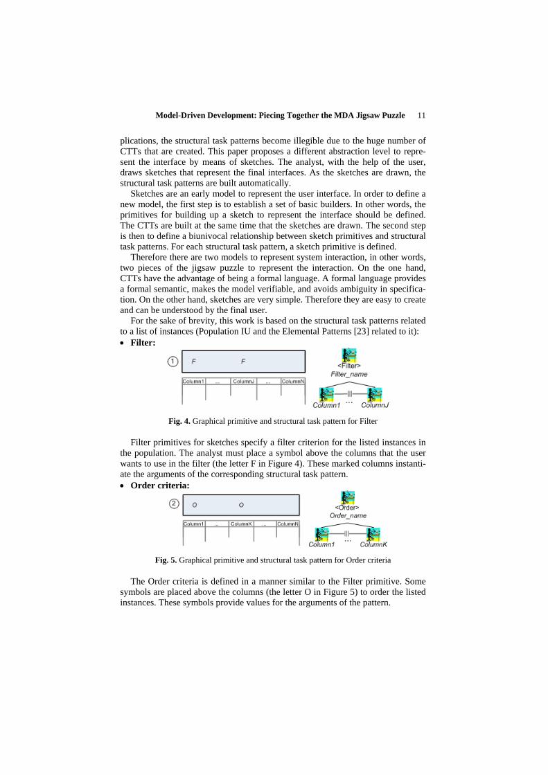
For the sake of brevity, this work is based on the structural task patterns related to a list of instances (Population IU and the Elemental Patterns [23] related to it): • Filter:
Fig. 4. Graphical primitive and structural task pattern for Filter
Filter primitives for sketches specify a filter criterion for the listed instances in the population. The analyst must place a symbol above the columns that the user wants to use in the filter (the letter F in Figure 4). These marked columns instanti-ate the arguments of the corresponding structural task pattern. • Order criteria:
Fig. 5. Graphical primitive and structural task pattern for Order criteria
The Order criteria is defined in a manner similar to the Filter primitive. Some symbols are placed above the columns (the letter O in Figure 5) to order the listed instances. These symbols provide values for the arguments of the pattern.

12 Oscar Pastor, Sergio España, José Ignacio Panach, Nathalie Aquino
• Actions:
Fig. 6. Graphical primitive and structural task pattern for Actions
The Actions, shown in Figure 6, represent operations that can be made with the selected instance in the population list. Some actions are very common (i.e., create a new instance, modify it, or delete it); others are specific to the system that is be-ing sketched. Actions instantiate the arguments of the structural task pattern. • Navigations:
Fig. 7. Graphical primitive and structural task pattern for Navigation
The analyst draws the navigation to system interfaces that implement queries or editions of objects related to the object source (Figure 7). For example, starting from an invoice line list, the user can navigate to the client data. The set of possi-ble destinations builds the arguments of this pattern. Once the arguments are built, the system task is in charge of carrying out the navigation. • Display set:
Fig. 8. Graphical primitive and structural task pattern for Display set
The display set primitive (Figure 8) specifies the columns of the population in-stances that will be shown graphically. This primitive is a set of columns that the

Model-Driven Development: Piecing Together the MDA Jigsaw Puzzle 13
analyst can assign a name to. The names of the columns inserted in the sketch provide the values of the structural task pattern arguments. • Population:
Once the correspondences between the structural task patterns and the third level of the Presentation Model patterns [23] are defined, the next step is to do the same with the second level of the Presentation Model patterns.
Fig. 9. Graphical primitive for Population
The Population primitive presents to the user a list of instances from a business object class (i.e., a list of customers). As Figure 9 shows, it may include all the primitives that represent elements of the third level in the OO-Method Presenta-tion Model through structural task patterns. Figure 10 presents the corresponding structural task pattern. The numbers in circles show the common parts.
Fig. 10. Population with CTT notation
As Figure 10 shows, the CTT that represents the population pattern includes in-teraction tasks that are in charge of filtering (Filter) and arranging (Order) the in-stances. The brackets represent grammatical-composition rules. In other words, they are points at which to hook the leaves to other structural task patterns. A sys-tem task is then used to show the instances of the objects (Display), which are fil-tered and ordered by the selected criteria on the screen. Finally, the user can carry out Action and Navigation operations with these instances, which are represented

14 Oscar Pastor, Sergio España, José Ignacio Panach, Nathalie Aquino
in the diagram by means of abstract tasks. All of these structural task patterns can be composed to model the interaction with a list of instances.
5 Case Study
This section shows the development process of a real system with the OO-Method methodology. This system is called AguasDeBullent, a water supply management system. In this case study, one of the possible routes across the MDA jigsaw puz-zle is followed, using many of the models proposed by the OO-Method. The case study starts with the stage of requirements capture. First, the analyst creates the Use Case Model. To keep the example simple, this paper focuses on one use case, List meters. This use case represents the functionality of showing a list with all the information about the water meters stored in the system.
Fig. 11. Use Case Model
Figure 11 shows the Use Case Model with a template that specifies the steps required to accomplish the goal of this use case. Again, for the sake of simplicity, the template does not fully comply with the notation described in [11] but it does specify the use case in detail.
Fig. 12. Sketch

Model-Driven Development: Piecing Together the MDA Jigsaw Puzzle 15
Once the functional requirements have been captured, the last step in require-ments capture is to model interaction requirements using sketches (see Figure 12)
The CTT that represents the sketch is automatically built (see Figure 13).
Fig. 13. CTT Model
Some of the views that compose the Conceptual Model (Object, Functional and Dynamic Models) can be derived from functional requirements applying the trans-formation rules detailed in [11]. The Presentation Model can be derived from the CTTs by applying transformation rules explained in [12]. This case study focuses on the Object Model (Figure 14a) and Presentation Model (Figure 14b).
Fig. 14. a) Object Model; b) Presentation Model

16 Oscar Pastor, Sergio España, José Ignacio Panach, Nathalie Aquino
Finally, the Model Compiler automatically generates the source code of the fully-functional application. The generated window for the use case “List meters” is shown in Figure 15.
Fig. 15. Final system
6 Conclusions and Future Work
The MDA paradigm is modelled in four layers: CIM, PIM, PSM and Code Model. This paradigm is used in several software production methods that distinguish be-tween the various abstraction levels with varying degrees of automation. In many cases, each MDA model is supported by a set of different models. Moreover, the specific models of each method can be built in a variable order, depending on a number of factors. These factors include: analyst’s preferences, user’s knowledge of computer systems, system size, and clarity of requirements. This fact, together with the large number of models proposed by the methods, results in a huge num-ber of possible combinations for abstract modelling of the system. Independently of the chosen order, all the models must be coherent with the user’s requirement and must represent a full system. This problem could be described as a ‘jigsaw puzzle’ construction, with each model of the method representing a piece of the jigsaw that must be joined to other pieces for the whole to succeed.
This issue is discussed in this paper using the example of the OO-Method ap-proach, a software production method based on the MDA paradigm. From among all the pieces of the OO-Method jigsaw puzzle, this paper focuses on those pieces designed to capture interaction requirements. The main reason for selecting these pieces is the fact that interaction modelling is often disregarded by the Software Engineering community. However, the Human-Computer Interaction Community has offered many successful techniques for capturing interaction requirements, a prime example are sketches. Sketches have been chosen to capture the interaction requirements in the OO-Method due to their simplicity. However, sketches cannot be used in an automatic transformation process unless we formalize their underly-ing language. We have chosen the ConcurTaskTree (CTT) notation to formally

Model-Driven Development: Piecing Together the MDA Jigsaw Puzzle 17
represent the sketches. CTTs allow the sketches to represent interaction unambi-guously; they can be validated and then transformed into the OO-Method Presen-tation Model. The implementation of the tool to draw sketches and to synchro-nously generate CTTs is planned as future work. This functionality, together with the transformation of the task model into the Presentation Model, will offer effi-cient technological support for automatically generating application interfaces and will allow early feedback from the user. This provides an interesting and specific example of how to put together the various pieces needed to create a complete, MDA-compliant software production process, the so-called ‘MDA jigsaw puzzle’.
We also plan to assess the efficiency of the proposed interaction-requirements technique, as well as the various alternatives for building the rest of the models. This will be done by means of empirical evaluation. Moreover, a case-base with the various methodological routes should be defined together with the factors that lead the analyst to choose one specific route.
References
[1] Ågerfalk PJ, Fitzgerald B (2006). Exploring the concept of method rationale: A concep-tual tool for method tailoring. In Advanced Topics in Database Research, Vol. 5., Siau K (ed.). Idea Group: Hershey, PA.
[2] Ågerfalk PJ, Ralyté J (2006). Situational Requirements Engineering Processes: reflect-ing on method engineering and requirements practice. Software Process: Improvement and Practice. John Wiley & Sons, Ltd. Online ISSN: 1099-1670.
[3] Bailey BP, Konstan JA (2003). Are Informal Tools Better? Comparing DEMAIS, Pen-cil and Paper, and Authorware for Early Multimedia Design. Human Factors in Com-puting Systems CHI’2003. New York,: ACM Press.
[4] Bernstein PA (2003) Applying Model Management to Classical Meta Data Problems. Proc. of Conference on Innovative Data Systems Research (CIDR) 2003.
[5] Brinkkemper S (1996). Method engineering: engineering of information systems devel-opment methods and tools. Information and Software Technology 38: 275–280.
[6] Brinkkemper S, Saeki M, Harmsen F (1999). Metamodelling based assembly techniques for situational method engineering. Information Systems 24(3): 209–228, DOI: 10.1016/S0306-4379(99)00016-2.
[7] Caetano A, Goulart N, Fonseca M, Jorge J (2002). JavaSketchIt: iIssues in Ssketching the lLook of Uuser iInterfaces. AAAI Spring Symposium. - Sketch understanding. AAAI Press: ; pp. 9–-14.
[8] Care Technologies: http://www.care-t.com. Last visited: July-2007. [9] Coyette A, Vanderdonckt J (2005). A Sketching Tool for Designing Anyuser, Anyplat-
form, Anywhere User Interfaces. INTERACT 2005, LNCS 3585; pp. : 550-564. [10] DeLaVara, J. L. and J. Sánchez (2007). Business process-driven requirements engi-
neering: a goal-based approach. In 8th Workshop on Business Process Modeling, De-velopment, and Support (BPMDS'07), CAiSE'07, Trondheim, Norway.De La Vara JL, Sánchez J (2007) Business process-driven requirements engineering: a goal based ap-proach. In Proc. of the 19th International Conference on Advanced Information Sys-tems Engineering (CAiSE’07). Norway (in press).
[11] Díaz I, Losavio F, Matteo A , Pastor O (2003). A Specification Pattern for Use Cases. Information & Management Journal, ( Elsevier Science B.V.) (0378-7206).

18 Oscar Pastor, Sergio España, José Ignacio Panach, Nathalie Aquino
[12] España S, Pederiva I, Panach JI (2007) Integrating Model-Based and Task-Based Ap-proaches to User Interface Generation. In Calvary, C. Pribeanu, G. Santucci, J. Vander-donckt (eds.) "Computer-Aided Design of User Interfaces VI". Kluwer: 255-263.
[13] Fitzgerald G (1991). Validating new information systems techniques: a retrospective analysis. In: Information Systems Research: Contemporary Approaches and Emergent Traditions (eds. H.-E. Nissen, H.K. Klein, R. Hirschheim), Elsevier Science Publishers B.V, pp. : 657-672.
[14] Fons J, Valderas P, Albert M, and Pastor O (2003). Development of Web Applications from Web Enhanced Conceptual Schemas. ER 2003, LNCS. Springer.pp. : 232-245.
[15] Gupta D, Prakash N (2001). Engineering methods from method requirements specifi-cations. Requirements Engineering 6(3): 135–160, DOI: 10.1007/s007660170001.
[16] ISO/IEC 9126-1 (2001), Software engineering - Product quality - 1: Quality model. [17] Karlsson F, Ågerfalk PJ (2004). Method configuration: Adapting adapting to situ-
ational characteristics while creating reusable assets. Information and Software Tech-nology 46(9): 619–-633, DOI:10.1016/j.infsof.2003.12.004.
[18] Karlsson F, Wistrand K (2006). Combining method engineering with activity theory: Theoretical grounding of the method component concept. European Journal of Informa-tion Systems 15(1): 82–90, DOI: 10.1057/palgrave.ejis.3000596.
[19] Landay J, Myers BA (2001). Sketching Interfaces: Toward More Human Interface De-sign. IEEE Computer 34. pp. 56–64.
[20] Lyytinen K, Welke R (1999). Guest editorial: Special issue on meta-modelling and methodology engineering. Information Systems 24(2): 67–69, DOI: 10.1016/S0306- 4379(99)00005–8.
[21] MDA: http://www.omg.org/mda Last visited: JulyJune-20072008. [22] Mirbel I, Ralyté J (2006). Situational method engineering: Combining assembly-based
and roadmap-driven approaches. Requirements Engineering 11(1): 58–78, DOI: 10.1007/s00766-005-0019-0.
[23] Molina P (2003), User interface specification: from requirements to automatic genera-tion, PhD Thesis, DSIC, Universidad Politécnica de Valencia, (in Spanish).
[24] Morgan T (2002) "Business Rules and Information Systems – Aligning IT with Busi-ness Goals", Addison-Wesley
[25] Newman MW, Lin J, Hong JI, Landay JA (2003). DENIM: An Informal Web Site De-sign Tool Inspired by Observations of Practice." Human-Comp. Interaction Inter. 18; pp. 259–324.
[26] Pastor O, González A, España S (2007). Conceptual alignment of software production methods. In Krogstie, J., Opdahl, A., & Brinkkemper, S. (eds.) “Conceptual modelling in information systems engineering”. Springer-Verlag: 209-228.
[27] Pastor Ó, Insfrán E, et al. (1997). OO-Method: An OO Software Production Environ-ment Combining Conventional and Formal Methods. Lecture Notes in Computer Sci-ence. 9th Conference on Advanced Information Systems Engineering (CAiSE'97). A. Olive and J. A. Pastor. Barcelona, Spain, Springer-Verlag.
[28] Paternò F, Mancini C, et al. (1997). ConcurTaskTrees: A Diagrammatic Notation for Specifying Task Models. In Proc. of the IFIP TC13 International Conference on Hu-man-Computer Interaction, Chapman & Hall, Ltd.: 362-369.
[29] Pederiva I, Vanderdonckt J, España S, Panach JI, Pastor O (2007) The Bbeautification of Aautomatically Ggenerated uUser iInterfaces. In Proc. Of of XI IFIP TC13 Interna-tional Conference on Human-Computer Interaction (INTERACT 2007). Brasil (in press); LNCS 4662:. 209-422
[30] Plimmer BE, Apperley M (2003). Software for Students to Sketch Interface Designs. Proc. Conf. on Human-Computer Interaction INTERACT’2003, IOS Press; pp.: 73–80.

Model-Driven Development: Piecing Together the MDA Jigsaw Puzzle 19
[31] Rittel H and Webber M (1973). "Dilemmas in a general theory of planning." Policy Sciences 4: 155-169.
[32] Schipper M, Joosten S (1996). A validation procedure for information systems model-ling techniques. In: Workshop on Evaluation of Modeling methods in Systems Analysis and Design, 8th Conf. on Advanced Information Systems Engineering (CAISE’96).
[33] Vanderdonckt J, Limbourg Q, et al. (2004). USIXML: a User Interface Description Language for Specifying Multimodal User Interfaces. Proceedings of W3C Workshop on Multimodal Interaction WMI'2004, Sophia Antipolis, Greece.
![Piecing it all together[1]](https://static.fdocuments.in/doc/165x107/5593f8001a28abb2088b4645/piecing-it-all-together1-55948f44c0061.jpg)