
Model-Based Test Case Selection and Generation for Real ... · PDF fileList of Enclosed Papers...
106
IT Licentiate theses 2006-002 Model-Based Test Case Selection and Generation for Real-Time Systems A NDERS H ESSEL UPPSALA UNIVERSITY Department of Information Technology
Transcript of Model-Based Test Case Selection and Generation for Real ... · PDF fileList of Enclosed Papers...

IT Licentiate theses2006-002
Model-Based Test Case Selection andGeneration for Real-Time Systems
ANDERSHESSEL
UPPSALA UNIVERSITYDepartment of Information Technology


Model-Based Test Case Selection and Generation forReal-Time Systems
BY
ANDERS HESSEL
March 2006
DIVISION OF COMPUTER SYSTEMS
DEPARTMENT OF INFORMATION TECHNOLOGY
UPPSALA UNIVERSITY
UPPSALA
SWEDEN
Dissertation for the degree of Licentiate of Philosophy in Computer Scienceat Uppsala University 2006

Model-Based Test Case Selection and Generation for Real-TimeSystems
Anders [email protected]
Division of Computer SystemsDepartment of Information Technology
Uppsala UniversityBox 337
SE-751 05 UppsalaSweden
http://www.it.uu.se/
c© Anders Hessel 2006ISSN 1404-5117
Printed by the Department of Information Technology, Uppsala University, Sweden

Abstract
Testing is the dominating verification technique used in industry today, andmany man-hours and resources are invested in the testing of software prod-ucts. To cut down the cost of testing, automated test execution becomesmore and more popular. However, the selection of which tests to be exe-cuted is still mainly a manual process that is error prone, and often withoutsufficient guarantees that the system will be systematically tested. A wayto achieve systematic testing is to ensure that the tests satisfy a requiredcoverage criterion.
In this thesis two main problems are addressed: the problem of how toformally specify coverage criteria, and the problem of how to generate atest suite from a formal system model, such that the test suite satisfies agiven coverage criterion. We also address the problem of how to generate anoptimal test suite, e.g., with respect to the total time required to executethe test suite.
Our approach is to convert the test case generation problem into a reach-ability problem. We observe that a coverage criterion consists of a set ofitems, which we call coverage items. The problem of generating a test casefor each coverage item can be treated as separate reachability problems. Weuse an on-the-fly method, where coverage information is added to the statesof the analyzed system model, to solve the reachability problem of a cover-age item. The coverage information is used to select a set of test cases thattogether satisfy all the coverage items, and thus the full coverage criterion.
Based on the view of coverage items we define a language, in the form ofparameterized observer automata, to formally describe coverage criteria. Weshow that the language is expressive enough to describe a variety of commoncoverage criteria in the literature. Two different ways to generate test suitesform a system model and a given coverage criterion are presented. Thefirst way is based on model annotations and uses the model checker Uppaal.The second way, where no annotations are needed, is a modified reachabilityanalysis algorithm that is implemented in an extended version of the Uppaaltool.
i

ii

Acknowledgments
I would like to thank my supervisor Paul Pettersson for supervising, co-authoring, and proofreading my work. There have been a lot of suggestionsfor improvements. Paul has been involved in all my research activities. AsPaul is active in both the testing group and the Uppaal group, I have hadthe opportunity to learn a lot from both communities.
I would also like to thank my co-supervisor Bengt Jonsson, who hasgiven me important feedback on the structure of the thesis. Bengt is co-author of Paper C, and a brilliant researcher that I am very glad to workwith. Bengt was my (main) supervisor for the first year, and helped methrough my master thesis report, which gave me my first scientific writinglessons. I am also thankful for the proofreading done by Johan Blom andJohn Hakansson.
Besides the supervisors I have had a very fruitful collaboration with myother co-authors; Johan Blom (Paper C), Kim G. Larsen, Brian Nielsen,and Arne Skou (Paper A) and the other members of the testing group, OlgaGrinstein and Therese Berg.
I would specially like to thank the people in the Uppaal group. Apartform the already mentioned persons I would also like to mention Wang Yi,Alexander David, Johan Bengtsson, Leonid Mokrushin, Gerd Behrmann,and John Hakansson. It has been a lot of coffee, especially with John. I alsohave had a lot of fun but that is another story.
Last but not least my fiance Anna, just for being you.
iii

iv

List of Enclosed Papers
Paper A:
Anders Hessel, Kim G. Larsen, Brian Nielsen, Paul Pettersson, and ArneSkou. Time-optimal Real-Time Test Case Generation using Uppaal. InAlexandre Petrenko and Andreas Ulrich, editors, Proceedings of the 3rdInternational Workshop on Formal Approaches to Testing of Software 2003(FATES’03), number 2931 in Lecture Notes in Computer Science, pages136–151. Springer–Verlag 2004.
Comments
I participated in the discussions, did the experiment measurements with myextension of Uppaal, and wrote part of the paper.
Paper B:
Anders Hessel and Paul Pettersson. A Test Case Generation Algorithm forReal-Time Systems. In H-D. Ehrich and K-D. Schewe, editors, Proceedingsof the 9th International Conference on Quality Software 2004 (QSIC’04),pages 268–273, IEEE Computer Society Press, September 2004
Comments
I implemented the extension of Uppaal described in the paper, did theexperiments, took part in the discussions, and wrote part of the paper.
Paper C:
Johan Blom, Anders Hessel, Bengt Jonsson, and Paul Pettersson Specifyingand Generating Test Cases Using Observer Automata In J. Gabowski andB. Nielsen, editors, Proceedings of the 4th International Workshop on For-mal Approaches to Testing of Software 2004 (FATES’04), volume 3395 inLecture Notes in Computer Science, pages 125–139, Springer–Verlag BerlinHeidelberg 2005.
Comments
I took part in the discussions and wrote part of the paper.
v

Other Work
Apart from the papers listed above, I have also participated in the followingwork:
• Anders Hessel, Kim G. Larsen, Brian Nielsen, Paul Pettersson, andArne Skou. Time-Optimal Test Cases for Real-Time Systems. Invitedpresentation. In Proceedings of the 1st International Workshop on For-mal Modeling and Analysis of Timed Systems 2003 (FORMATS’03).
• Johan Blom, Anders Hessel, Bengt Jonsson, Paul Pettersson. Spec-ifying Test Cases Using Observer Automata. Extended abstract. InP. Pettersson and Wang Yi, editors, Proceedings of the 16th NordicWorkshop on Programming Theory Oct 2004. Technical Report 2004-041, ISSN 1404-3203. Department of Information Technology, UppsalaUniversity, October 2004.
• Anders Hessel, Kim G. Larsen, Brian Nielsen, Paul Pettersson, andArne Skou. Time-optimal Real-Time Test Case Generation usingUPPAAL. Extended abstract, Real-Time in Sweden 2003 - RTiS’03Vasteras.
• Anders Hessel, Kim G. Larsen, Marius Mikucionis, Brian Nielsen, PaulPettersson, and Arne Skou. Automated Model-Based ConformanceTesting of Real-Time Systems. Book chapter. In J. Bowen, M. Har-man, and R. Hierons, editors, Formal Methods and Testing, SpringerVerlag. Submitted.
vi

Contents
1 Introduction 1
1.1 Real-Time Systems . . . . . . . . . . . . . . . . . . . . . . . . 1
1.2 Testing . . . . . . . . . . . . . . . . . . . . . . . . . . . . . . 2
1.3 Test Case Selection . . . . . . . . . . . . . . . . . . . . . . . . 3
2 Modeling Timed Systems 5
2.1 Untimed State Machines . . . . . . . . . . . . . . . . . . . . . 6
2.2 Timed Automata . . . . . . . . . . . . . . . . . . . . . . . . . 7
3 Coverage 8
3.1 Logic Coverage . . . . . . . . . . . . . . . . . . . . . . . . . . 9
3.2 Data Flow Criteria . . . . . . . . . . . . . . . . . . . . . . . . 11
3.3 Coverage on Projected States . . . . . . . . . . . . . . . . . . 13
4 Test Case Generation by Model Checking 14
4.1 Adding Coverage Information to States . . . . . . . . . . . . 15
4.2 Observers . . . . . . . . . . . . . . . . . . . . . . . . . . . . . 16
4.3 Generating Test Suites from Timed Automata . . . . . . . . . 19
5 Summary of Papers 21
5.1 Paper A: Time-optimal Real-Time Test Case Generation us-ing Uppaal . . . . . . . . . . . . . . . . . . . . . . . . . . . . 21
5.2 Paper B: A Test Case Generation Algorithm for Real-TimeSystems . . . . . . . . . . . . . . . . . . . . . . . . . . . . . . 22
5.3 Paper C: Specifying and Generating Test Cases Using Ob-server Automata . . . . . . . . . . . . . . . . . . . . . . . . . 22
6 Related Work 23
6.1 Models . . . . . . . . . . . . . . . . . . . . . . . . . . . . . . . 23
6.2 Observers . . . . . . . . . . . . . . . . . . . . . . . . . . . . . 25
6.3 Tools . . . . . . . . . . . . . . . . . . . . . . . . . . . . . . . . 26
7 Conclusions and Future Work 26
A Time-optimal Real-Time Test Case Generation using Up-
paal 33
1 Introduction 35
2 Related Work 36
vii

3 Timed Automata and Testing 38
3.1 Timed Automata . . . . . . . . . . . . . . . . . . . . . . . . . 38
3.2 Uppaal and Time Optimal Reachability Analysis . . . . . . 39
3.3 Deterministic, Input Enabled and Output Urgent TA . . . . . 393.4 From Diagnostic Traces to Test Cases . . . . . . . . . . . . . 41
4 Test Generation 42
4.1 Single Purpose Test Generation . . . . . . . . . . . . . . . . . 42
4.2 Coverage Based Test Generation . . . . . . . . . . . . . . . . 434.3 Test Suite Generation . . . . . . . . . . . . . . . . . . . . . . 45
4.4 Environment Behavior . . . . . . . . . . . . . . . . . . . . . . 46
5 Experiments 47
5.1 The Touch Sensitive Switch . . . . . . . . . . . . . . . . . . . 475.2 System Size and Environment Behavior . . . . . . . . . . . . 49
5.3 Search-order and Guiding . . . . . . . . . . . . . . . . . . . . 51
6 Conclusions and Future Work 52
B A Test Case Generation Algorithm for Real-Time Systems 57
1 Introduction 59
2 Preleminaries 60
2.1 Timed Automata . . . . . . . . . . . . . . . . . . . . . . . . . 60
2.2 Deterministic, Input Enabled and Output Urgent TA . . . . . 61
2.3 UPPAAL and Testing . . . . . . . . . . . . . . . . . . . . . . 61
3 Test Generation Algorithm 62
3.1 Test Sequence Generation . . . . . . . . . . . . . . . . . . . . 62
3.2 Test Suite Generation . . . . . . . . . . . . . . . . . . . . . . 64
3.3 Time Optimal Test Suites . . . . . . . . . . . . . . . . . . . . 64
4 Implementation 65
4.1 Overview . . . . . . . . . . . . . . . . . . . . . . . . . . . . . 66
4.2 Layers . . . . . . . . . . . . . . . . . . . . . . . . . . . . . . . 66
4.3 Dynamic Size of Bitvectors . . . . . . . . . . . . . . . . . . . 66
5 Experiments 67
6 Conclusion 68
C Specifying and Generating Test Cases Using Observer Au-
tomata 71
1 Introduction 73
viii

2 Extended Finite State Machines 75
3 Observers 78
3.1 Observer Predicates . . . . . . . . . . . . . . . . . . . . . . . 793.2 How Observers Monitor Coverage Criteria . . . . . . . . . . . 813.3 Examples of Observers . . . . . . . . . . . . . . . . . . . . . . 83
4 Test Case Generation 84
4.1 Algorithms . . . . . . . . . . . . . . . . . . . . . . . . . . . . 844.2 Bitvector Implementation . . . . . . . . . . . . . . . . . . . . 864.3 Implementation Efforts . . . . . . . . . . . . . . . . . . . . . . 86
5 Conclusions 87
ix

x

1 Introduction
The fact that unreliable computer systems can cause severe problems in oursociety is indisputable. Apart from the personal and material damage anincorrect system can cause to its user or owner, it can also be costly for themanufacturer. For these reasons manufacturers strive to make their systemsas error-free as possible.
For a system to function correctly, there are two things that are impor-tant: validation, to ensure that the right system is built, and verification,to ensure that the system is built right. In this thesis we will consider theverification problem.
Testing is the dominating verification method for increasing confidencein a computer system. It is the process of exercising a system in a controlledenvironment and examine if its behavior complies with the requirements ofa system. There are other quality improvement techniques used by softwareengineers as part of the verification process. Other techniques are code walkthroughs, code inspections, and code reviews.
The purpose of testing is to reveal faults in the system. Testing canonly show the presence of faults, not their absence. There are two mainchallenges in testing, to select and to execute test cases.
We will consider testing of the logical and temporal correctness of a sys-tem, i.e., functional testing. There are many other types of testing. Amongthem stress testing, which is often used interchangeably with both load test-ing, and performance testing, i.e. testing when the system is heavily utilized.A duration test is a test of the ability of a system to run over a longer periodof time, and robustness testing, sometimes called negative testing, conductedby sending invalid input data, are also outside the scope of the thesis.
1.1 Real-Time Systems
A real-time system is a system where the behavior of the system depends notonly on the input but also on the timing of the input. Such system can alsohave requirements on the timing of its outputs. In order to test a real-timesystem, we have to take into account not only what inputs to supply to thesystem, but also when to supply them. For correct behavior of a real-timesystem, a response should not only provide correct values, but the valuesshould also be provided at the right time-points.
We illustrate a few different timing requirements. (i) A machine that isfilling up soda bottles must stop after a certain amount of time in order notto overfill. Hence the specification of an embedded controller of the machineshall require an output from the controller to stop filling after that time.
(ii) A computer that distinguishes between single- an double-clicks froman input device must measure the time between two consecutive clicks. Firstafter waiting the maximum time bound for a double-click, the computer can
1

HarnessImplementation
Test Results
Test SuiteTest Case
Verdicts
Oracle
SpecificationGeneration
Under TestTest
Figure 1: Black box testing
determine a first click as a single-click. If a second click arrives earlier, thenthe two clicks should be interpreted as a double-click.
(iii) A car control system might have to react to a brake signal within agiven time bound. During the reaction time, the engine ignition must stillbe on time with the requested precision.
1.2 Testing
Testing of system behavior can be categorized into white box and black boxtesting. In white box testing, also called structural testing, or glass box test-ing, tests are derived from knowledge about the structure of the software andfrom implementation details. In black box testing, also called functional test-ing, test data are derived from the specified functional requirements withoutconsidering the internal program structure [ABC82]. The implementationand the test cases can be developed in parallel, by two separate teams.
In Figure 1, a common setting for black box testing is shown. From aspecification of the system, test cases are derived. A test case includes inputvalues that stimulate the system to test some chosen functionality. Thiscould be parameters to start the system or sequences of input data. Forreal-time systems also the timing of the input data should be supplied. Thetest case generation results in a collection of test cases called a test suite.
2

The generation may be done manually or automatically.
After the test suite is produced, a test harness executes the test suiteagainst the implementation under test. This produces a test result, which iscompared to the expected result, prescribed by the specification, by a testoracle. The test oracle delivers a verdict for each test case in the test suite.Ideally, the verdict of a test should be pass or fail. If all generated testspass, then this shows conformance between the test and the specification.
A failed test is a system failure, i.e., the system does not deliver theexpected result (erroneous or with incorrect timing). If the test is carriedout under the specified circumstances, then the failure shows that the systemhas an error, i.e., a design flaw. When a test fails we identify the fault (thedefect) causing of the failure.
If a test has failed, the system (as a whole), does not conform to the test.The test itself might not conform to the specification, and in that case thetest case should be changed and not the system. Further, the specificationmay not express the intention of the system. In this case the the specificationmay be changed and the test cases rewritten.
Often the expected test result can be incorporated into the test cases sothat the test harness can make the verdict itself; in this case the oracle isa part of the test harness. This is especially good if the test cases consistof long sequences, because the test harness can stop further interaction andexecute the next test case if it discovers an error.
1.3 Test Case Selection
For a program (or a function) that takes a finite set of input parameters, eachof which has a specified input domain, testing all combinations of parametervalues is referred to as exhaustive testing. The number of parameter combi-nations can be very large, which makes exhaustive testing not applicable inmost practical cases.
One way to reduce the number of test cases in a test suite, and still testall functionality in a specification, is by using partition testing. In partitiontesting the value domains are divided into equivalence classes, and the testsare selected so that at least one value from each equivalence class is tested.Any values within the specified value domains can be chosen arbitrary. Forrobustness testing, also values that exceed the minimum or maximum boundof the domains can be chosen. Boundary values or extreme values are thevalues that lie close to the border between valid and invalid data. It istypically very interesting to select boundary values for tests.
If a system can receive arbitrarily long input sequences, and has aninternal state that is updated after each input then exhaustive testing is notpossible. Two examples of such systems are (i) a compiler that reads a sourcecode file as input (stream) and (ii) an elevator controller that repeatedlyreacting on input events. In addition to input sequences being arbitrarily
3

long, the timing of the inputs matter for a real-time system.If the internal structure of a system is known, as in white box testing, test
cases can be generated with knowledge of the actual code that is exercisedduring test execution. It is possible to make one test suite tailored to testone specific part of the code. The code can be instrumented to report whichlines are exercised, e.g., by using the gcov tool [vHW03]. A test suite canbe said to cover partially or fully the code with respect to some measure ofcoverage, e.g., use of every statement or every branch in the code. Such codecoverage is typically used to measure the thoroughness of a given test suite.It assists engineers to improve their test suites by pointing out the partsnot exercised. In Figure 1, the test suite would be affected by the specificimplementation if white box testing is used.
Model-based testing is a black box technique where a model is used asspecification. Often the model is examined by a tool to generate test suites.In structural testing the code coverage can be used as a measure of thor-oughness for a test suite. In the same way coverage on the model can beused as a measure of thoroughness for a test suite in model-based testing.Such a measure can be evaluated even before a test case is executed. As testcase generation can be automated in model-based testing, the test cases donot have to be constructed by hand from the specification.
A test purpose is a specific objective (or property) that the tester wouldlike to test, and can be seen as a specification of a test case. Test purposescan be used to select test cases. As an example of a test purpose, we consider“test of a state change from state A to state B” in a model. For this purposea test case should be generated that covers the specific state change. If wemake a test purpose for all specified state changes, and generate test casesfor them, then we have a test suite that covers all specified state changesin the model. As a test case can cause several state changes, and thusfulfill several test purposes, a test suite might have fewer test cases than thenumber of test purposes it fulfills.
In model-based testing, non-deterministic specifications can be used ifthe cause of some decision is unknown or the details that determine thedecision are abstracted away. Because of the non-determinism, we will notalways have one possible response from an implementation, but several.We can use adaptive test cases, which requires that the test harness has adecision tree for each test case.
If a test purpose is to exercise a particular state change in the model,and we make a test case for this state change, then we cannot be surethat we will succeed (even with a correct system), if the specification allowsnon-determinism. A decision tree can have arbitrary long branches withoutany guarantee of capturing the desired behavior. When we reach a leaf ofa decision tree, we still might not have been able to exercise the desiredbehavior. We cannot give the verdict fail, which would indicate that thesystem is non-conformant with the test specification. Still, the test purpose
4

is not fulfilled, and thus the verdict pass would be misleading. In this casewe give the test the verdict inconclusive. We can run this test again and wemay get another result.
In this thesis we will use test cases with only one expected continuation.A test harness that gives the verdict itself can abort the test case if anoutput of a system is not expected. Only if the full test case is executed theverdict pass is given. Our test cases will thus be a sequence of inputs andoutputs, not necessarily alternating. In the case of timed systems, a delaywill be specified between each input or output.
2 Modeling Timed Systems
In model-based testing a model is used as the specification. A model is anabstraction of a desired system behavior, which can consist of the combinedbehavior of applications, OS, hardware etc. Benefits of modeling includesunderstanding of the specification in an early stage, and exposition of ambi-guities in the specification and the design. For some types of models, modelchecking tools (such as SPIN [Hol97] or Uppaal [LPY97]) can be used toformally verify properties of the model, in order to find errors in a modelbefore implementing it. Errors found late in a project are known to be moreexpensive than errors found early. Thus, it is important to make a correctspecification.
The abstraction process results in a model. Different types of abstrac-tions often have to be made to construct a model. An integer variable thatis used only by a model in a decision that evaluates whether the value is oddor even, can be reduced to two abstract values “integer-odd” and “integer-even”. An IP-number used when communicating with a system is typicallysomething that can be completely abstracted away.
The right level of abstraction is crucial for any model-based technique tobe successful. If a model is too abstract, the targeted functionality cannotbe tested, because details important to distinguish test cases are missed. Ifthe model is too concrete, the construction of the model is as error proneas a full implementation. When model-based testing is used, the controlstates are typically in focus, and data are abstracted as much as possible.This is possible only if the data does not affect the control behavior of theimplementation, e.g., the payload in a network protocol.
An abstract test case generated from a model is on the same abstrac-tion level as the model. If we have an abstract test case with the abstractvalues “integer-odd” and “integer-even” for a variable, then we can replace“integer-odd” and “interger-even” with, e.g., 0 and 1. Only when all ab-stact values have been replaced with concrete values, the test case can beexecutable. Other data that have been completely abstracted away must ofcourse also be added, e.g., IP-numbers.
5

For a given system, it is possible to produce many models of differentaspects. If there are different functionalities that are orthogonal to eachother, then it is often easier to validate each functionality in a separatemodel than to validate a combined model. To have a valid model is the baserequirement of all model-based testing.
2.1 Untimed State Machines
In this section we will introduce state machines without time. A finite statemachine (FSM) is an abstract machine with a finite set of locations L, a finiteset of edges E, and a finite set of actions Act. One of the locations l0 ∈ L isthe initial location. An FSM uses actions to interact with its environment.An edge is a triple (l, α, l′) ∈ E that has a source location l ∈ L and adestination location l′ ∈ L and is labeled with an action α ∈ Act.
In our case the actions can be partitioned in input actions, output ac-tions, and internal actions. We will use the convention that an input actionis suffixed with “?”, and an output action is suffixed with “!”. An internalaction has no suffix.
An extended finite state machine (EFSM) consists of locations L, edgesE, actions Act, and variables V . The location l0 ∈ L is the initial location.Each variable x has a value domain. An edge is a quintuple (l, g, α, u, l′) ∈ Ethat has a source location l ∈ L and a destination location l′ ∈ L and islabelled with a guard g, an action α, and an update u. The guard g is apredicate over V , and the update u is an assignment where each variable vis assigned a value from an expression over V . If there is no assignment thevariable values are unchanged.
A state of an EFSM is a tuple 〈l, σ〉 where l ∈ L and σ is a mapping fromV to values. The initial state is 〈l0, σ0〉 where σ0 is the initial mapping. Atransition between two states, i.e., from 〈l, σ〉 to 〈l′, σ′〉 is possible if thereis an edge (l, g, α, u, l′) ∈ E where the g is satisfied for the valuation σ, σ′
is the result of updating σ according to u, and α is an action that requirecommunication with the environment, if the action is not internal.
If we assume that every variable has a finite domain in an EFSM, thenthe EFSM can be viewed as a compact notation of an FSM. It is possible tounfold the EFSM such that each EFSM state is an FSM location and eachEFSM transition is an FSM edge.
In Figure 2 an EFSM modeling a parking ticket machine is shown. Theinitial location is named display. There is one variable amount that isinitially 0. As a first transition the EFSM can only output the actiondisplayPayMore that models displaying the message “Pay more”. In thewait location, the user can add 5 credit coins that increment the value ofamount. If the user has paid enough for a ticket, the EFSM outputs theaction displayPressT icket, else it outputs the action displayPayMore. Af-ter an output displayPressT icket from the EFSM the user can input ticket
6

wait
display
gotTicket
add5?amount:=amount+5
amount < 10
amount >= 10displayPressTicket!
amount < 10displayPayMore!
ticket?amount >= 10
amount:=amount-10
printTicket!
Figure 2: EFSM model of a parking ticket machine.
and get an output printT icket in return. Note that the wait location is usedin three different states 〈wait, 0〉, 〈wait, 5〉, and 〈wait, 10〉. In the first twothe user is allowed to add more credits, and in the last the user is allowedto request a ticket.
2.2 Timed Automata
We use timed automata [AD94] to model timed systems. Let X be a set ofnon-negative real-valued variables called clocks. Let G(X) be a set of guardson clocks generated by the grammar
g ::= x ./ c | x − y ./ c | g1 ∧ g2
where x, y ∈ X, c ∈ N, and ./∈ {<,≤,=,≥, >}. A timed automaton consistsof locations L, edges E, actions Act, and clocks X. One of the locationsl0 ∈ L is the initial location. An edge (l, g, α, r, l′) ∈ E has a source locationl ∈ L and a destination location l′ ∈ L and is labelled with a guard g ∈ G(X),an action α ∈ Act, and set of clocks to reset r ⊆ X called reset.
A state of a timed automaton is a tuple 〈l, σ〉 where l ∈ L and σ ∈ RX≥0
is a mapping from X to non-negative real-time values. The initial state is〈l0, σ0〉 where σ0 is the initial mapping where every clock is mapped to 0.There are two kinds of transitions, discrete transitions and delay transitions.A discrete transition between two states written 〈l, σ〉
α−→ 〈l′, σ′〉 is possible
if there is an edge (l, g, α, r, l′) ∈ E where the guard g is satisfied for thevaluation σ, where r is an update so that σ′ = σ[x/0] for all x ∈ r, and α is
an action. In a delay transition between two states written 〈l, σ〉d−→ 〈l, σ+d〉,
where d ∈ R>0, and σ +d denotes the result of incrementing all clock valuesin σ with d. Locations can have invariants, that set an upper bound on aclock value. The bound constrains the delay so that the automaton is notallowed to stay in the location forever. Timed automata use dense time,which means infinite precision of clocks.
7

UNARMED dc2ARMEDc<=C
ARMEDb<=B BOOMED
dc2UNARMEDc<=C,b<=B
click? c:=0 click? b:=0c<C boom!b==B
b==B boom!
c==C click?c:=0
click?c<C
c==C
Figure 3: Timed automaton describing the function of the explosive pen inthe movie Golden Eye
In Figure 3 a timed automaton modeling an explosive pen is shown. Adouble-click, i.e., an input click twice within the time bound C, will armthe pen to explode after B time units. Here B and C are positive integers.An armed pen can be unarmed by another double-click if the double-click issupplied before the explosion. The explosion is modeled in the automatonby the output boom. If the pen works correctly it could be used for itspurpose safely. Needless to say, incorrect use could be devastating.
3 Coverage
Time and money are commonly used criteria to determine whether to endthe testing of a product or not. Unfortunately these criteria do not set anyquality standard on the product. When should then a system be consideredto be tested thoroughly enough? Without any objective measure this is ahard question. If parts of the system are not exercised at all, then the systemis probably not tested thoroughly enough.
A test suite can be measured with respect to the amount of code it ex-ercises, e.g., by measuring the number of statements executed in the systemunder test. The number of statements exercised can be compared with thetotal number of statements, and the percentage can be calculated. A cri-terion for enough thoroughness can be to exercise a certain percentage ofthe number of statements. Here we use statements as our measure, butwe could also use the exercised branches between statements. If we use thestatement measure, a test suite is said to cover a statement, if the statementis exercised (at least once) during an execution of the test suite. Coveragewith respect to the statement measure is called statement coverage [Mye79],and coverage with respect to the branch measure is called branch coverage[Mye79]. Statement coverage and branch coverage are examples of coveragecriteria that can be used to measure coverage provided by a test suite.
8

There are many other coverage criteria. We will give an overview ofseveral other coverage criteria later in this section. For this purpose we willuse the terminology from Paper C of this thesis, to explain the coveragecriteria. Any coverage criterion consists of a set of measurable items. Wewill use coverage item as a generic term for a measured item. For statementcoverage, exercising a statement will fulfill a coverage item. There will beone coverage item for each statement. Thus, to achieve full (statement)coverage all statements must be exercised.
It may not be possible to list all (feasible) coverage items without sophis-ticated analysis of the code. Even then, a coverage criterion must describehow to identify a coverage item and how to distinguish coverage items fromeach other.
Coverage criteria have so far been discussed in the context of coverageon code, but it is similar to measure coverage for a model. For model-based testing, analysis of coverage with respect to a criterion, can be usedto guide test suite generation. When a black box test suite is executed, theactual code coverage can be measured. Based on the result, additional testcases can be added. White box measures can thus complement test suitesgenerated with black box techniques.
In an EFSM (or other models as FSM or TA) to visit all locations iscalled location coverage, and to traverse all edges is called edge coverage. Inthe remainder of this section, we first describe some classic logic-coveragecriteria in their original context of code. We then describe data flow andprojected state coverage in an EFSM context.
3.1 Logic Coverage
White-box testing is concerned with the degree of thoroughness to whichtest cases exercise the logic (or source code) of the program. We distinguishbetween decisions that decide the continuation of the program control andstatements that are non-branching. In an if-statement (in a C-like syntax)
if (x == 2 ∧ y ≥ 6) s1; else s2;
the decision is “x == 2 ∧ y ≥ 6”. It decides which of the branches ofstatements, s1 or s2, the program control should follow. Subexpressionsthat do not contain ∧, ∨, or ¬ are called conditions, e.g., x == 2 and y ≥ 6.The execution order or branching inside a decision is not considered.
We have already described the statement coverage criterion, which re-quires a test suite to execute each statement in the system under test. If100% coverage cannot be achieved, then there must be some dead code in theimplementation. Statement coverage is similar to line coverage or basic blockcoverage. In basic block coverage a sequence of non-branching statements isthe measured unit, but because basic blocks are non-branching, basic blockand statement coverage are equivalent metrics, given that full blocks are
9

always executed. In statement coverage each statement corresponds to acoverage item. The statement identifies the coverage item.
We have also described decision coverage (DC), but under the namebranch coverage, which stipulates that each possible branch must be tra-versed, e.g., both the true and the false branch must be traversed for anif-statement. In a switch-statement all cases must be traversed. This meansthat the decision expression is considered as one unit without consideringits conditions.
For a decision, e.g., c1 ∨ c2 in an if-statement, where c1 and c2 are condi-tions, DC can be achieved by two test cases where the conditions evaluate to{c1 = true, c2 = false} and {c1 = false, c2 = false}, i.e., the truth value ofcondition c2 is not changed. In DC each outgoing branch from each decisioncorresponds to a coverage item. The branch identifies the coverage item.
The condition coverage criterion (CC) [Mye79] is sensitive to each con-dition as it require all possible outcomes of each condition in a decision. Ingeneral CC is a stronger criterion than DC, but this is not always true.For a decision, e.g., c1 ∨ c2 in an if-statement, CC can be covered bytest cases where the conditions evaluate to {c1 = true, c2 = false} and{c1 = false, c2 = true}. As both evaluations of c1 ∨ c2 become true, DC isnot fulfilled and the false branch will never be traversed. In CC a coverageitem is identified by a tuple 〈ci, b〉, where ci is a condition in the code, andb defines the truth value of ci, i.e., there are two coverage items for everycondition.
The multiple condition coverage (MCC) [Mye79] requires that all pos-sible combinations of outcomes of the conditions in each decision must beexercised. Let di be an index that identifies the ith decision, ni be the num-ber of conditions in di, and Ki be a tuple of truth values of the possibleoutcomes of the conditions of di. In MCC a coverage item is identified by〈di, kj〉, where kj ∈ Ki is an outcome of the conditions of the decision di.
A relaxation of the MCC criterion is the modified condition/decisioncoverage (MC/DC) criterion created by Boeing [RCT92, CM94]. It requires(for each decision) every condition to modify the outcome of the decisionwithout changing the truth values of the other conditions in the decision. Asthe modifying condition must change the outcome of the decision withoutchanging the other truth values MC/DC subsumes both DC and CC.
In MC/DC a coverage item is identified by 〈di, cj〉, where cj is a conditionin a decision di, so that cj has made the the decision di both true and falsewithout changing the other conditions in di. We will use the intermediateinformation 〈cj , kj , true〉 and 〈cj , kj , false〉, where kj is a tuple of truthvalues for the other conditions than cj in di. Because of the requirementthat the other conditions in the decision di are not allowed to change theirtruth values 〈cj , kj , true〉 cannot exist without 〈cj , kj , false〉. This mightlook a lot like CC, but we have different conditions for the coverage items.Again for a decision, e.g., c1 ∨ c2 in an if-statement, CC can be covered
10

by test cases where the conditions evaluate to {c1 = true, c2 = false} and{c1 = false, c2 = true}. All the possible CC coverage items are covered,i.e., 〈c1, true〉, 〈c1, false〉, 〈c2, true〉, and 〈c2, false〉. If MC/DC is appliedthe for the same test suite cover no items. If we add a case where {c1 =false, c2 = false}, then MC/DC will be covered, i.e., {c1 = true, c2 =false}, {c1 = false, c2 = false} will give 〈c1〉, because we have 〈c1, k1, true〉and 〈c1, k1, false〉 where k1 = (false), only c1 change. The second coverageitem 〈c2〉 (only c2 change) is covered by {c1 = false, c2 = true}, {c1 =false, c2 = false}. Note that the decision must be visited twice to fulfillone coverage item. It is possible that this requires two test cases.
Switch coverage [Cho78], is a classic coverage criteria. The possible pathof control flows can not only split up in decisions they can also join, e.g.,after an if statement. A “switch” is a combination of the entrance and theexit branch of a basic block. If a basic block has two incoming and twooutgoing branches there are four possible “switches”. Put it another way, acoverage item of the switch coverage criterion is a pair 〈bin, bout〉, where bin
and bout are branches between basic blocks. The coverage item 〈bin, bout〉 isfulfilled if the branch bin is the entrance and bout is an exit of a basic block.This can be extended to n-tuples where n consecutive branches are exercisedto fulfill the coverage item.
3.2 Data Flow Criteria
Data flow testing criteria [CPRZ89] are an important part of the standardcoverage criteria. We first make some definitions. A variable is defined whenit is assigned a new value, e.g., c is defined in the statement c := k + 1. Avariable is used when it is part of a computation or a predicate. An exampleof a computation-use (c-use) is k in the statement c := k+1, and an exampleof a predicate-use (p-use) is x in a guard x == 1. A variable has a p-use inall types of decisions. When we refer to the locations of the definitions or ofthe uses we will use EFSM terminology, i.e., both assignments and guardsare located at edges. Without loss of generality we restrict the number ofassignments on an edge to one in the further discussion, thus an assignmentcan be referenced by an edge. A path is a sequence of edges traversed by anautomaton consecutively.
Assume a variable x is defined at edge ed. Consider a path ed, e1, . . . ,en, eu, where the variable x is not redefined in the sub-path e1, . . . , en, thenthe definition at ed reaches the edge eu. In this case the sub-path e1, . . . ,en is a definition-clear path with respect to x.
Reach coverage [Her76, LK83], also referred to as definition-use pair (du-pair) coverage is a commonly used criterion. It requires that a test suiteincludes all paths from a definition of a variable x to all the reachable edgeswhere x is used. A coverage item 〈x, ed, eu〉 where x is a variable, ed is anedge where variable x is defined, and eu is an edge with a use. If a definition
11

of a variable x at edge ed reaches a use of x at edge eu with a definition-clearpath with respect to x, then the coverage item 〈x, ed, eu〉 is fulfilled. Noticethat two different variables x and y can both be defined in ed and used ineu still 〈x, ed, eu〉 and 〈y, ed, eu〉 would not always be covered for the samepaths. This is because a definition-clear path from ed to eu with respect tox might not be a definition-clear path with respect to y and vice versa.
Another criterion is context coverage [LK83] or rather definition contextcoverage. A context of a variable definition is the edges where the variablesused for the definition is defined, e.g., for a statement x := y +z the contextis (ey, ez) if y was defined at ey, and z at ez, when x is defined. The criterionrequires that a test suite includes all paths so that for every definition of avariable x, every different context of the definition is represented. A coverageitem for context coverage is a pair 〈ei, ki〉 where ei is an edge with a use,and ki is a tuple of the edges where the variables used in ei is defined. Thesize if ki depends on the used variables in ei. For used variables v1, . . . , vn
in ei, ki consists of e1, . . . , en so that v1 is defined in e1 etc.A similar criterion is ordered context coverage [LK83]. An ordered context
of a variable definition is a context where the edges in the context is listedin the order of their definition, e.g., for a statement x := y + z the orderedcontext is (e1, e2) where y was defined at e2, and z at e1, and the definitionof y is more recent of the two. A coverage item for ordered context coverageis similar to one in context coverage with the difference that the positionsin the tuple ki are sorted in the order by the occurrence in the path to ei.
The all-paths [RW85] criterion is fulfilled if all possible paths are includedin the test suite. This is not feasible for general EFSMs that can havearbitrary long paths or for code that has infinite loops. We consider onlysystems with a finite number of paths with a specific entry and exit point.The coverage criterion is fulfilled if all paths from the entry to the exit pointare included in the test suite. A coverage item for the all-paths criterionconsists of a single parameter p that is a full path from an entry point toand exit point.
The all-defs [RW85] criterion is one of the easiest data flow criterion tofulfill. It is enough to find one use for each definition. If we have a paththat contains a definition of a variable that reaches a use, then another paththat contains another use of the same definition does not cover anythingmore. The criterion requires that a test suite includes paths so that everydefinition has at least one use. A coverage item for the all-defs criterion〈x, ed〉 requires that a definition at edge ed of a variable x has a definition-clear sub-path with respect to x to an edge where x is used. Notice that thenumber of uses do not affect the number of coverage items for the all-defcriterion.
The all-uses [RW85] criterion is another name for reach coverage. Theall-p-uses [RW85] criterion is similar to all-uses, but the use at eu must bea p-use. The all-c-uses [RW85] criterion is similar to all-uses, but the use at
12

eu must be a c-use.
The all-du-path [RW85] criterion requires that all (definition-clear) pathsbetween a definition and a use with respect to the variable are included inthe test suite. A coverage item 〈x, p〉 is covered if there exists a definition-clear path p with respect to a variable x, where p starts with an edge wherex is defined, and ends with an edge where the variable is used. The all-du-paths criterion is stronger than all other definition-use criteria, becauseevery du-path must be covered.
In [Nta88], the Ntafos’ required k-tuples criteria are described. A 2-tupleis simply a du-pair. We denote a du-pair (x1, e1, e2), where the variable x isdefined at edge e1 and used at edge e2. If at e2, the variable x1 affects thedefinition of x2 in another du-pair (x2, e2, e3), then the two du-pairs are heresaid to be coupled. Two coupled du-pairs forms a 3-tuple. Note that for a3-tuple there are three edges involved. The criterion, for k-tuples, requiresthat a test suite includes paths so that every k-tuple is included.
A coverage item 〈e1, x1, . . . , xk−1, ek〉 for k > 2, where a variable x1 isdefined at edge e1, a variable xk−1 is used at edge ek, the edge ei where2 ≥ i ≥ k − 1 is an edge where a variable xi−1 affects a another variable xi,and there is a definition-clear path from ej to ej+1 with respect to xj where1 ≥ j ≥ k − 1. Thus the definition at edge e0 affects the use at edge ek.
3.3 Coverage on Projected States
We have earlier described location coverage, i.e., to visit all locations in themodel. In an EFSM, locations together with valuations of variables are usedto define states. If we simply take the location of a state, then we have madea projection from a state to a location.
Let M be an EFSM. We can describe the operational semantics of Mas a labeled directed graph G = (V,E), where vertices V corresponds tothe states of M and the labeled arcs E corresponds to the transitions ofM where the label is the action used. Let λ : V → V ′ be the projectionfunction that maps states in V to states in V ′. As an example λloc : V → L,where L is the set of locations in M , maps a state to the location of thestate, e.g., λloc(〈l, σ〉) = 〈l〉. If λ(v) = λ(v′), where v, v′ ∈ V then v and v′
are in the same equivalence class.
Let ρ be an equivalence relation and [v] denote an equivalence class,where v ∈ V . A projected state machine graph [FHNS02] under a equivalencerelation ρ is defined to be the labeled directed graph G′ = (V ′, E′), whereV ′ is the set of equivalence classes under ρ, and E′ is the set of labeledarcs, where an arc labeled a from [v] to [v′] in E′ exists if ∃s, s′. λ(s) =[v] ∧ λ(s′) = [v′] ∧ 〈s
a→ s′〉 ∈ E.
In Figure 4 a projected state machine graph is shown. We have projectedthe parking ticket machine from Figure 2 on the variable amount. Theequivalence classes are amount = 10 and amount 6= 10. Notice that the
13

amount_not_10 amount_10
add5?
displayPayMore! displayPressTicket!
ticket?
add5?
printTicket!
Figure 4: A projected state machine graph. The ticket machine in Figure 2has been projected on the amount variable.
projection is non-deterministic, the add5 action is associated with two arcswithout restrictions. As there is no other information in the projected statesthan the equivalence class the target projected state is non-deterministic.
If we make a test suite that cover every arc in the projected state machinegraph, we note that there are two arcs labeled add5? to be covered, whereasthere is only one edge with add5? in the original model. A test suite mustcover both to add a five credit coin when the total amount will not sum upto ten credits and when it does sum up to ten.
If we project the parking ticket machine from Figure 2 on equivalenceclasses that are separated by both the location and the amount variable,we would get the full state-space of the ticket machine. If there where morevariables used in the ticket machine the projection might have been usefulto concentrate on the behavior around the amount variable.
4 Test Case Generation by Model Checking
A model checker can formally verify temporal properties of a system model.Reachability properties is one type of properties that a model checker canverify. A reachability property specifies that a state with a certain propertyshould be reachable, e.g., “There exists a reachable state s so that P holdsfor s”. A state is defined as reachable in a model, if it can be reached fromthe initial state by zero or more transitions.
One way for a model checker to check reachability is to explore thereachable states from the initial state, either until it finds a state where theproperty holds or until there are no more states to explore. A path to sucha state is called a witness trace. It is a trace from the initial state to a statewhere the property holds.
In the following, we will see how to transform the problem of test case
14

generation into a reachability problem. We will use witness traces to gen-erate a collection of test cases that fulfills the requested coverage criterion.Each coverage item can be seen as a specific subproblem that can be solvedindependently. We will first describe how to generate a test case for onecoverage item, and then show how make a test suite to cover a full coveragecriterion. The main idea is to use a reachability property to determine ifa coverage item can be fulfilled. We must thus construct a property thatbecomes true when a coverage item is fulfilled.
4.1 Adding Coverage Information to States
To evaluate a coverage item, we extend model states with auxiliary infor-mation. The purpose of the information is to determine whether a coverageitem is fulfilled by the path to a state or not. We update the auxiliary infor-mation at each model transition. The actual coverage criterion determinesthe specific auxiliary information needed.
For the edge coverage criterion a coverage item for an edge ei, denoted〈ei〉, is fulfilled if the edge has been traversed. In this case, when we traversean edge ei we update the auxiliary information with the coverage item 〈ei〉.We let reachability properties include auxiliary information, and we canthus check the reachability of a state that includes a coverage item 〈ei〉. Ifreachable, a witness trace for the coverage item can be generated.
Location and edge coverage are examples of coverage criteria that canbe fulfilled momentarily, i.e., in a state or at a transition. For data-flowcriteria this is not the case. We need to use information of the history ofthe path. Let 〈x, ed, eu〉 be a coverage item for a definition-use pair wherex is a variable that is defined at edge ed and used at edge eu. To concludethat 〈x, ed, eu〉 is fulfilled when we traverse eu we must know that the mostrecent definition of x was at ed. Let 〈x@e1〉 represent that x is defined ate1. This is added to the auxiliary information, but is replaced when x isdefined at another edge.
We have now seen how to find a witness trace for a single coverage item.Note that a coverage item that once was fulfilled in a state will also befulfilled in its successor states, thus the covered items increase monotonically.If we can find a state where all the items of a coverage criterion are covered,we can generate a test case that satisfy the full coverage criterion.
In general, it may not be possible to find a single path that fulfills allcoverage items for a criterion. In this case we can combine different pathsso that they together achieve the requested coverage. This can be done byadding a special “reset” transition to the model. The reset transition putsthe model in its initial state, but keeps the achieved coverage items in theauxiliary information. Other information is discarded, e.g., where a variablewas last defined.
If a model checker finds a path p1 with coverage C1, and then, after a
15

tl = L
loc(display) loc(wait) loc(gotT icket)
(i) (ii)
loc(L)
q0q0
tl=display
tl=wait
tl=gotT icket
Figure 5: Two views on an observer for location coverage for the parkingticket machine in Figure 2
reset transition, finds a path p2 with coverage C2 the total coverage achievedwill be C1 ∪ C2 etc. If the coverage in C1 ∪ C2 satisfies the property themodel checker will produce a witness trace p1 · reset · p2. We assume thata reset transition can be recognized in the trace. We can now make a testsuite consisting of a test case tc1 based on p1 and a test case tc2 based onp2.
4.2 Observers
There are many coverage criteria in the literature. A tool could implementsupport for them one by one, but this would not be very flexible. In Paper Cof this thesis we suggest a language to formally specify coverage criteria usingobserver automata. The observer language is described for EFSM models,but other models such as timed automata would be applicable as well.
An observer is an automaton defined by locations and edges that are la-beled with predicates. An observer automaton has an initial location markedis marked • and a set of accepting locations marked }. An observer collects,in a path, the auxiliary information that are used in the coverage criterion.The information must include status for all coverage items. Intuitively theobserver follows the transition of an EFSM, and the set of possible observerlocations is the auxiliary information.
An observer has always the possibility to stay in the initial location orin an accepting location. A location that is not an initial or an acceptinglocation have to take an observer edge at each EFSM transition. If there areno enabled edges for a location, it is removed from the auxiliary information.
In Figure 5 two observers are shown for location coverage of the park-ing ticket machine in Figure 2. We recall that the parking ticket machinehas three locations named display, wait, and gotT icket. The observer in
16

Figure 5 (i) has three accepting location, one for each possible EFSM loca-tion in Figure 2. After a transition in the EFSM, the predicate t l=wait issatisfied if wait was the target location of the EFSM transition. Observerlocation loc(wait) represents coverage item 〈wait〉 for the location coveragecriterion. It is similar for the other locations and the other edges.
In Figure 5 (ii) a parameterized observer is shown. If the parking ticketmachine in Figure 2 is observed then the observer (i) and (ii) are equivalent.For Figure 5 (ii) the possible locations of the EFSM is the domain of pa-rameter L, and thus there is one accepting observer location (and coverageitem) for each location.
The parameterized observer has the advantage over the non-parameterizedthat the domains of the parameters do not have to be specified at the sametime as the observer automaton. Thus a parameterized observer expressesa coverage criterion for any EFSM. A parameterized location represents thecollection of locations obtained by instantiating its parameters, and similarfor the edges.
Technically we superpose an observer onto an EFSM, so that each stateare of the form 〈〈l, σ〉 ‖ Q〉, where 〈l, σ〉 is a state of the EFSM, and Q is aset of locations of the observer. A transition 〈〈l, σ〉 ‖ Q〉 ; 〈〈l′, σ′〉 ‖ Q′〉 ofthis construct is possible if (i) a transition of the EFSM 〈l, σ〉 ; 〈l′, σ′〉 ispossible and (ii) Q′ is a set of every possible q′ such that there is an observertransition q ; q′ where q ∈ Q. Observer transitions are done in response toan EFSM transition, thus the details are known about the EFSM transition(including the source and destination EFSM states). An observer locationq in Q may have several or zero, possible transitions.
From the user’s point of view an observer automaton can be seen asnon-deterministic. None or many outgoing edges can be enabled from aparameterized location. The transition from Q to Q′ is however determin-istic. As the transition is calculated by subset construction, the underlyingsemantics are deterministic.
In Figure 6 an observer for the all-uses coverage criterion is shown. Theinitial location is marked q0. The observer has one parameterized acceptinglocation du. We use the convention to denote observer parameters with cap-ital letters. The parameters can refer to variables, edges, locations, variablevaluations, etc., in the model. In this example we use the X parameter fora variable, and the E, E′ parameters for two edges. If a variable amount isdefined at edge e1 in an EFSM transition, the observer edge with predicatedef(amount) ∧ edge = e1 will become true. It is then possible for the ob-server to make a transition from q0 location to the q1(amount, e1) location.As long as there is no redefinition of amount in the EFSM, there is a pos-sibility to stay in the location because of the self loop. If Q includes thelocation q1(amount, e1) and amount is used in an EFSM transition at edgee2 a transition to the accepting location du(amount, e1, e2) is possible, i.e.,the coverage item 〈amount, e1, e2〉 is fulfilled. Note that a transition from
17

q0
q1(X, E)
du(X, E, E′)
¬def (X)
def (X) ∧ edge=E
use(X) ∧ edge=E′
Figure 6: An all-uses (du-pair) observer
q1(amount, e1) back to itself may also be possible by the self loop edge ifamount is not defined in the EFSM transition, i.e., the definition of amountin e1 may have other uses than in e2 and the location q1(amount, e1) shouldthus be kept in the auxiliary information.
4.3 Generating Test Suites from Timed Automata
We will assume that a specification is modeled as a network of timed au-tomata compatible with the modeling language used in Uppaal. Such mod-els has no external actions, we therefore need to model both a system andits environment. This is usually done by making an unconstrained envi-ronment. Such environment can at any time synchronize with the externalactions of the system model. In Figure 8 an environment is shown that hasno restrictions on when it can synchronize with the click action except aftera boom action has been received.
We will make a distinction between the specified system that we callcontroller and the environment of the systems that we call environment.Both the controller model and the environment model can consist of severalautomata, and internal communication is possible, both inside the controllerand the environment model. The relation between the automata duringmodel checking and real world testing is shown in Figure 7. The upperpart shows the model partitioned as described above, and the lower partshows the implementation under test (IUT) and the tester, e.g., the testharness or a human user. The communication channel between the controllerand environment in the modeling world has a corresponding communicationmedium in the real world.
To avoid generating test cases for which the system is not specified, the
18

System during Test Case Execution
IUT Tester
out
in
Controller Environmentout
in
Model of System and Environment
... is an abstraction of ...
Figure 7: Model based testing
environment model can only provide the controller model with stimuli forwhich the system is specified. Stimuli outside the scope of the specificationshould not be provided. Other useful limitations to the environment modelscan be to model a tester with limitations, e.g., a tester that cannot providestimuli infinitely fast.
A possible environment to generate test cases for the explosive pen inFigure 3 is shown in Figure 8. The environment can synchronize with theexplosive pen on the click? action without timing constraints by the edgedecorated with click!. When the explosive pen explodes the environmentsynchronize with the boom action. After the boom no more testing can bedone and the system must be reset to continue.
Let C = 2 and B = 10, (seen from the side of the environment) thetimed traces
TC 1: click! · 0 · click! · 10 · boom?
and
TC 2: click! · 2 · click! · 0 · click! · 0 · click! · 2 · click! · 0 · click! · 0 · click! ·0 · click! · 9 · click! · 1 · boom?
are two possible test cases. As all edges are traversed the all-edges coverage
19

CanClick
Done
click!
boom?
Figure 8: Timed automaton describing an possible environment to generatetest cases for the explosive pen in Figure 3.
criterion is satisfied. The sequence of locations passed in the exercise for thetest cases are for
TC 1: UNARMED, dc2ARMED, ARMED, BOOMED
and for
TC 2: UNARMED, dc2ARMED, UNARMED, dc2ARMED,ARMED, dc2UNARMED, ARMED, dc2UNARMED, UNARMED,dc2ARMED, ARMED, dc2ARMED, BOOMED.
When a witness trace is found for the required coverage, we convert thetrace to a test case. The witness trace is a timed trace, i.e., an alternatingsequence of inputs or outputs, and delays. Uppaal provides us with aconcrete trace, i.e., the trace has instantiated delays.
The trace can include transition that are internal for the controller or theenvironment. During test execution, we can only observe the interface of theimplementation under test. A test case consists only of observable actionsand delays. On the other hand the witness trace includes all transitions inthe model. We project the trace on the interface between the controller andthe environment, i.e., we remove all internal actions and transitions, and wesum up the delays between the remaining actions.
. If the remaining sequence has consecutive delays they are summed upto the delay between the observable actions.
When we provide inputs according to a timed trace generated by Up-
paal, we expect no deviation between the behavior of the system and thebehavior in the timed trace. An unexpected response from the implemen-tation under test could mean that the rest of the trace will be infeasible,because of the fact that the internal state of the system differs from themodeled state during generation. To be able to execute the generated testcases we restrict the timed automata model. Our restrictions are similar asthe ones in [SVD01].
20

We call an automaton that fulfills our restrictions a deterministic inputenabled output urgent timed automata (DIEOU-TA). For short the restric-tions means that: (i) an input or a delay from one semantic state, leads onlyto one semantic state, (ii) no delay can be done when an input is offered,(iii) if the system can send an output no conflicting input, output, or delayis permitted.
To make a concrete test case we transform each action of the modelin the trace to the real-world stimulus that the action models. The resultis a concrete test case that can be executed by a test harness to test animplementation of the system.
We have not described what order to search the state space, i.e., whichsuccessor to generate at a given moment. The most common search ordersused in reachability are breadth first and depth first. Besides search orders,Uppaal can be instructed to return the witness that has the shortest traceor the fastest trace. There are also support for heuristic algorithms thatare variations of the A∗ [BFH+01, LBB+01] algorithm. The A∗ algorithmscan speed up the generation performance if an admissible heuristics can befound.
By combining our encoding of coverage and the ability of Uppaal to findthe fastest trace, we can generate test suites with a requested coverage thatare time-optimal, i.e., no test suite with the same coverage can be executedfaster. The generation is done by using the fastest trace algorithm, and savestime for the user that gets the implementation tested as fast as possible.
If we let time be a cost so that a time unit delay gives a cost of one costunit, we can associate a constant cost with the reset transition. For pathsincluding resets, we give the resets a cost for the “inconvenience”. The resetcost could be very different depending on whether the whole system has tobe restarted or if it is simple to reinitialize the system. The cost of a resetcould be set very high, and thus the number of resets will be kept as low aspossible for optimal test suite.
5 Summary of Papers
5.1 Paper A: Time-optimal Real-Time Test Case Generation
using Uppaal
In this paper we demonstrate how the problem of test case selection can betransformed to a reachability problem. We show how test suites for bothsingle test purposes and coverage criteria can be generated with the Uppaal
model checking tool. Especially, we apply the minimum cost reachabilityanalysis, found in Uppaal, to generate the test suite that has the shortestexecution time, and still fulfills the given coverage criteria. The rationalefor this is not primary to stress the system but not to wait an unnecessary
21

long time when executing the test cases. In this paper we also defines thedeterministic input enabled output urgent timed automata.
We annotate the model to keep track of coverage items. The coverageis saved in model variables. If a state is found where all such variables areset, then the trace to that state is a trace which fulfills the coverage criteria.Thus, the problem of finding a trace that fulfills a coverage criteria has beenreduced to a reachability problem. If it is impossible to find full coveragewith one test case, we can decorate the model so that the system can berestored to its initial state, but keeping the coverage item information.
We also present some experiments on how this technique scales and onhow the environment automata affect the time and memory used in the testcase generation. A major drawback of this approach is that the model hasto be annotated for every new coverage criterion. In Paper B we describean implementations which makes such modifications superfluous.
5.2 Paper B: A Test Case Generation Algorithm for Real-
Time Systems
In this paper we automate the test case generation of the coverage criteriathat where described in Paper A. We present an abstract algorithm for sym-bolic reachability analysis with coverage and describes some aspects of anprototype implementation. We also show some experiments which demon-strate the benefits of a pruning technique we use.
In the paper we do not use any manually annotated auxiliary variablesto store the information of the covered coverage items as in Paper A. Insteadwe keep track of the information automatically by extending the ordinaryUppaal state with additional data. We represent both the covered itemsand (as in the case of the definition use pair data-flow criteria) informationwhich affects the future possibilities to cover items.
In the implementation, a bit-vector B is used to store the coverage items.If we already have explored an Uppaal state with coverage items B and findthe same state again (or a subset of it as the clock evaluations are symbolic)but with coverage items B′ we do not continue to search with the secondstate if its coverage items is a subset of the coverage items in the first. This ispossible because we favor better coverage and more coverage will not destroythe property. In Paper A we stop the search only if we have equal coverage,i.e., B = B′.
The main criticism of Paper B is that only the criteria that are imple-mented in the tool are available to the user. It would be convenient if userscould define their own coverage criteria. This is addressed in Paper C.
22

5.3 Paper C: Specifying and Generating Test Cases Using
Observer Automata
In Paper C we present a technique for specifying coverage criteria and amethod for generating test suites for systems whose behaviors can be de-scribed as extended finite state machines (EFSM). The technique is demon-strated for EFSMs but is also applicable for other types of models as, e.g.,timed automata. We use observer automata to monitor traces. The tech-nique is expressive and we demonstrate this by specifying a number of well-known coverage criteria based on control- and data-flow information usingobserver automata.
We assume that reset can be used as in Paper A to enable all coverageitems to appear in one trace. Further we representat the set of observerlocations in a state as a bit-vector, and show how to encode the transitionfrom one set of observer locations to another, given the EFSM transition.
Even if observers has its most obvious benefits with data-flow coveragecriteria they can also be used to express equivalence class-based coveragecriteria as projection [FHNS02] of the current EFSM state. It is up to theimplementer to supply macros and/or a language allowing users to createtheir own macros, e.g., for equivalence class partitions of state variable val-ues. The observer language proposed in Paper C makes it possible to expresscoverage criteria that combines data-flow properties, e.g., a variable that isfirst defined and later used, and equivalence class projections, e.g., take thelocation from the state as parameter.
6 Related Work
In the literature, there are several work of test case generation from specifi-cations of timed systems [SVD01, CKL98, ENDKE98, CO00, Kho02, NS03,LMN05].
6.1 Models
To make the automata deterministic Springintveld et al [SVD01] use sim-ilar restrictions as we do in Paper A. For testing purposes, they discretizethe time into a grid automata (with constant delays) based on regions andgenerate test cases using Chow’s classical W-algorithm [Cho78] based oncharacterization sets.
En-Nouaary et al. [ENDKE98] extends the generalized partial W-method(Wp-method) [LvBP94] to timed input/output automata. In a grid-automatonwith synchronized actions all actions are discrete including delays, as in anFSM. The automata used have no restrictions as our automata and if weconsider input and delay as tester actions and output and clock reset asresponse actions such automaton is non-deterministic. En-Nouaary et al.
23

transform the automaton to an non-deterministic automaton with transi-tions labeled with tester action/response action pairs. This is an observablenon-determinism on which the generalized Wp-method can be applied. Af-ter the last transition the current state can be calculated by the observedresponse. We do not use discrete states in the model we are generating from,thus our state space is not sensitive to the size of the delays in the samemanner. For number of clocks used, the complexity increase roughly equalfor the both approaches.
Typical for methods using the W-method or other checking sequencetechniques is that they rely on a fault hypothesis. Typically the faults can be;action or output faults, transfer fault, extra transition in implementation,and missing transition in the implementation. The method is sensitive forthe number of states in the specification. In our method we often can findtest cases without even generate all states in the specification.
It can be helpful to give restrictions of the environment to avoid gener-ating uninteresting test cases. These restrictions can also be seen as guidingto especially wanted test cases, e.g., it can be of the form of a test purpose.In [CKL98], Castanet et al. make a synchronous product between a systemautomaton and an acyclic test purpose automaton, where the test purposeautomaton has an accepting subset. If this subset can be reached then atest of the given purpose can be generated. We show in Paper A that thisapproach is valid in our setting.
In [CO00] Cardell-Oliver uses Uppaal timed automata as we do. Check-ing sequences are not used for the full system but for some aspects. Testviews that are part of a test plan are used to focus on some functionality,which make the size of the system suitable for generating test cases. Testviews are related to test purposes.
In [Kho02] Khoumsi uses timed automata, assuming determinism butnot output urgency. The model is transformed into an se-FSA, which isan automaton where clocks and their operations have been replaced withset and expire actions. The translation keeps the behavior of the automata.This is equal to the symbolic representation in Uppaal with the extensionof equivalence classes done in [NS03] to get feasible traces. A test executionprogram can get exact instructions from the se-FSA for the needed timersand the values that must be set, the output to be observed, and the inputspossible to send. The expiring of the timers and the output gives the test ex-ecution program information of the state changes the implementation shoulddo in order to conform to the specification. Test sequences are generatedfrom the se-FSA with the generalized Wp-method.
Another type of restricted non-determinism is event recording automata(ERA) [AFT94], which is a determinizable subset of timed automata. ERAis basically timed automata where the is one clock per action and a clockis reset on the corresponding action. ERA is used by Nielsen and Skouin [NS03] where the model is determinized and the symbolic states found
24

is divided into equivalence classes. In test cases where the specificationgives the implementation freedom to choose an output (among several) theoutcome trace is classed as a may trace. If it does not give the freedom thenthe trace is a must trace. May and must traceability was proposed by DeNicola and Hennessy [NH84]. The base of the symbolic state exploration ofNielsen and Skou’s tool is Uppaal, as in our tool. We do not require ERA,but deterministic automata. In fact as we require deterministic automatawe always know what clocks are reset when. We consider the symbolic statespace to be too large (even without the partition) to be generated for testcase selection. Instead we select the test suite according to the coveragecriteria. On the other hand some states might have to be visited severaltimes before a coverage item is fulfilled. Thus, our state space is sometimeseven larger because of the auxiliary information added. We use the samewitness trace function from Uppaal as [NS03].
Higashino et al. [HNTC99] use timed I/O automata where the timingof the specified system is not controllable. The intervals where the actioncan happen are analyzed and may and must test are generated with theUIOv-method where, for each state, a transfer sequence and a succeedingunique input/output sequence are treated as a test case.
Krichen and Tripakis [KT04] uses non-deterministic and partially observ-able timed automata. They also analyze must and may preorder of traceinclusion. Further they generate digital clock-tests which measure time witha periodic clock. This is useful for a test program in practice and similar tothe approach in [Kho02]. The method can simulate clock drifts which cangenerate less strict test cases. The method can be used both offline (beforetest case execution) and online (during test case execution).
Another work using online testing is [LMN05] by Larsen et al. In[LMN05] the tool T-Uppaal is presented (now renamed to Uppaal TRON).As our tool, TRON is based on Uppaal but has no restrictions to deter-ministic automata as our tool has. TRON tracks possible states of thespecification during execution and chooses input randomly. If there is nopossible state an error is reported. There is not yet any guidance in TRON,so no specific coverage is guaranteed.
6.2 Observers
Our coverage observers are related to the work of Mandrioli et al. [MMM95]using specification written in the TRIO language that extends classical tem-poral logic to deal explicitly with time measures. In [MMM95] test casesare generated using a history generator and a history checker. In [HJL03]Hakansson et al. use TRIO to generate a test oracle. The explicit purpose ofthe test oracles in [HJL03] is to check safety properties during test execution.
Temporal logic is also used in the work of Hong et al [HLSU02, HCL+03]to describe data-flow coverage criteria. They use a model checker to generate
25

test cases for a CTL formula. The implicit for-all quantification in our workis a novelty. Hong et al. have to make a reachability search for each coverageitem. The witness returned is a trace which covers that particular coverageitem.
There is also a relation to the work of Friedman et al. [FHNS02]. The pa-rameters of our observers can be used in ways similar to projection coverage.To extract the location from a state or the edge used to make a transitionis a projection of the state space. Friedman et al. use a test generationtool GOTCHA. Various projections on the state graph of an EFSM can bespecified with a simple programming interface provided by GOTCHA.
6.3 Tools
There is a wide variety of test tool both in academia and in industry apartfrom the already mentioned tools. The STG tool [CJRZ02] a symbolictest generation tool using the IOSTS (Input Output Symbolic TransitionSystem) [RdBJ00]. Rusu et al. generates test cases from test purposes in[RdBJ00] this is similar to our test purposes generated in Paper A. The STGtool is related to TorX [dBRS+00] by du Bousquet et al. STG and TorXare conformance test tools based on the ioco [Tre96, TdV00] conformancerelation defined by Tretmanns. Bouquet and Legeard describes the BZ-Testing-Tools in [BL03] – a tool-set for animations and test generation fromB, Z, and statechart specifications.
Other more loosely related tools are tools for model checking of code.The Bandera Tool Set in [HD01] model check properties of concurrent javasoftware. Bandera compiles java code and a specification in BSL (Ban-dera Specification Language) to the input language of several model check-ers. Bandera uses program slicing and data-abstraction (abstract interpre-tation) on the model driven by the specification when it transform the codeto the model checking languages. BLAST [BCH+04] is a verification toolfor checking temporal safety properties of C programs. It constructs anabstract reachability tree with program locations and truth values of pred-icates. It has two levels of specification languages, i.e., observer automataand relational queries. Observer automata monitors safety properties andrelational queries that may specify both structural and semantic propertiesmuch as our coverage observers although not used for the same purpose.Other tools that model check programs are SLAM [BR01] by Microsoft andJFP [VHB+03] by NASA.
7 Conclusions and Future Work
In this thesis we have shown how the problem of test case generation fromtimed automata models can be transformed into a reachability problem suit-able for a model checker. By annotating the states with auxiliary informa-
26

tion about coverage, we can use Uppaal to generate time-optimal test suiteswith an on-the-fly method.
We have also described a tool that can be used for test case generationwithout annotations in the model. Information about coverage items areautomatically collected, for several coverage criteria. An improved algorithmfor reachability of properties including coverage has been described.
Further, we have proposed a generic language to specify coverage criteria.The language is based on observer automata. We also show a method forgenerating test suites from EFSM models, given a coverage criterion specifiedwith coverage observers.
Since an observer is an automaton with control structure, it is possibleto specify, e.g., data-flow coverage criteria. The observer parameters makeit possible to combine variables, locations, etc., from the current state into aprojection, that can be a part of a coverage item. In this sense we combinetwo useful techniques in model-based testing.
We believe that the use of coverage observers simplifies the specificationof coverage criteria. The language can be used to specify and combine mostof the popular coverage criteria, as well as new criteria specified by users.
Currently we are developing a tool, called coXer, for test case genera-tion. The tool is a completely new version of the tool described in Paper B,and includes a tailored coverage observer language for networks of timedautomata. The tool has been applied in a case study of a WAP gatewaytogether with the telecom company Ericsson AB.
As future work, we will elaborate with different search strategies to rem-edy the blow up of the state space that comes with the coverage data addedto the states. The coXer tool contains a separate module for coverage han-dling, which could be plugged into other tools than Uppaal. To specify astandard API for such a coverage module would be an opening for other toolsto utilize the work, e.g., SPIN and Uppaal TRON. Until now we have notbeen able to use clocks in observers. This together with other types of cov-erage that are not addressed yet as boundary coverage, condition coverage,etc., will be topics for future work.
27

References
[ABC82] W. Richards Adrion, Martha A. Branstad, and John C. Cher-niavsky. Validation, verification, and testing of computer soft-ware. ACM Comput. Surv., 14(2):159–192, 1982.
[AD94] R. Alur and D. L. Dill. A theory of timed automata. TheoreticalComputer Science, 126(2):183–235, 1994.
[AFT94] R. Alur, L. Fix, and Henzinger TA. Event-clock automata: adeterminizable class of timed automata. In Proc. 6th Int. Conf.on Computer Aided Verification, volume 818 of Lecture Notesin Computer Science. Springer–Verlag, 1994.
[BCH+04] D. Beyer, A. J. Chlipala, T. A. Henzinger, R. Jhala, and R. Ma-jumdar. The blast query language for software verification. InR. Giacobazzi, editor, Proc. 11th International Static Analy-sis Symposium (SAS 2004), volume 3148 of Lecture Notes inComputer Science, pages 2–18. Springer–Verlag, 2004.
[BFH+01] G. Behrmann, A. Fehnker, T. Hune, K. G. Larsen, P. Petters-son, and J. Romijn. Efficient Guiding Towards Cost-Optimalityin Uppaal. In T. Margaria and W. Yi, editors, Tools and Algo-rithms for the Construction and Analysis of Systems : 7th In-ternational Conference, (TACAS’01), number 2031 in LectureNotes in Computer Science, pages 174–188. Springer–Verlag,2001.
[BL03] F. Bouquet and B. Legeard. Reification of executable testscripts in formal specification-based test generation: The javacard transaction mechanism case study. In FME 2003, volume2805 of Lecture Notes in Computer Science, pages 778–795.Springer–Verlag, 2003.
[BR01] T. Ball and S.K. Rajamani. Automatically validating temporalsafety properties of interfaces. In M.B. Dwyer, editor, Proc.8th International SPIN Workshop on Model Checking Software(SPIN’01), volume 2057 of Lecture Notes in Computer Science,pages 103–122. Springer–Verlag, 2001.
[Cho78] T.S. Chow. Testing software design modeled by finite-statemachines. IEEE Trans. on Software Engineering, 4(3):178–187, 1978.
[CJRZ02] D. Clarke, T. Jeron, V. Rusu, and E. Zinovieva. Stg: A sym-bolic test generation tool. In J.-P. Katoen and P. Stevens, edi-tors, Tools and Algorithms for the Construction and Analysis of
28

Systems : 8th International Conference, (TACAS’02), volume2280 of Lecture Notes in Computer Science, pages 324–356.Springer–Verlag, 2002.
[CKL98] R. Castanet, O. Kone, and P. Laurencot. On The Fly TestGeneration for Real-Time Protocols. In International Confer-ence in Computer Communications and Networks, Lafayette,Lousiana, USA, October 12-15 1998. IEEE Computer SocietyPress.
[CM94] J.J. Chilenski and S.P. Miller. Applicability of modified condi-tion/decision coverage to software testing. Software Engineer-ing Journal, 9(5):193–200, Sept. 1994.
[CO00] R. Cardell-Oliver. Conformance Testing of Real-Time Sys-tems with Timed Automata. Formal Aspects of Computing,12(5):350–371, 2000.
[CPRZ89] L. A. Clarke, A. Podgurski, D. J. Richardsson, and Steven J.Zeil. A formal evaluation of data flow path selection criteria.IEEE Trans. on Software Engineering, SE-15(11):1318–1332,November 1989.
[dBRS+00] L. du Bousquet, S. Ramangalahy, S. Simon, C. Viho, A. Be-linfante, and R.G. de Vries. Formal test automation: The con-ference protocol with tgv/torx. In H. Ural, R.L. Probert, andG. von Bochmann, editors, IFIP 13th Int. Conference on Test-ing of Communicating Systems(TestCom 2000). Kluwer Acad-emic Publishers, 2000.
[ENDKE98] A. En-Nouaary, R. Dssouli, F. Khendek, and A. Elqortobi.Timed Test Cases Generation Based on State Characteriza-tion Technique. In 19th IEEE Real-Time Systems Symposium(RTSS’98), pages 220–229, December 2–4 1998.
[FHNS02] G. Friedman, A. Hartman, K. Nagin, and T. Shiran. Projectedstate machine coverage for software testing. In Proc. ACMSIGSOFT International Symposium on Software Testing andAnalysis, pages 134–143, 2002.
[HCL+03] H.S. Hong, S.D. Cha, I. Lee, O. Sokolsky, and H. Ural. Dataflow testing as model checking. In ICSE’03: 25th Int. Conf. onSoftware Enginering, pages 232–242, May 2003.
[HD01] John Hatcliff and Matthew Dwyer. Using the bandera toolset to model-check properties of concurrent java software. vol-ume 2280 of Lecture Notes in Computer Science, pages 39–58.Springer–Verlag, 2001.
29

[Her76] P.M. Herman. A data flow analysis approach to program test-ing. Australian Computer J., 8(3), 1976.
[HJL03] J. Hakansson, B. Jonsson, and O. Lundqvist. Generating on-line test oracles from temporal logic specifications. Int. Journalon Software Tools for Technology Transfer, 4(4):456–471, 2003.
[HLSU02] H.S. Hong, I. Lee, O. Sokolsky, and H. Ural. A temporal logicbased theory of test coverage. In J.-P. Katoen and P. Stevens,editors, Tools and Algorithms for the Construction and Analy-sis of Systems : 8th International Conference, (TACAS’02),volume 2280 of Lecture Notes in Computer Science, pages 327–341. Springer–Verlag, 2002.
[HNTC99] T. Higashino, A. Nakata, K. Taniguchi, and A. R. Cavalli.Generating Test Cases for a Timed I/O Automaton Model. InG. Csopaki, S. Dibuz, and K. Tarnay, editors, Testing of Com-municating Systems: Method and Applications, IFIP TC6 12th
International Workshop on Testing Communicating Systems(IWTCS), September 1-3, 1999, Budapest, Hungary, volume147 of IFIP Conference Proceedings, pages 197–214. Kluwer,1999.
[Hol97] G.J. Holzmann. The model checker SPIN. IEEE Trans. onSoftware Engineering, SE-23(5):279–295, May 1997.
[Kho02] A. Khoumsi. A method for testing the conformance of real-time systems. In W. Damm and E-R. Olderog, editors, FormalTechniques in Real-Time and Fault-Tolerant Systems: 7th In-ternational Symposium, FTRTFT 2002, volume 2469 of LNCS.Springer–Verlag, September 2002.
[KT04] M. Krichen and S. Tripakis. Black-box conformance testing forreal-time systems. In Laurent Mounier Susanne Graf, editor,Proc. 11th International SPIN Workshop on Model CheckingSoftware (SPIN’04), volume 2989 of Lecture Notes in ComputerScience, pages 182–197. Springer–Verlag, 2004.
[LBB+01] K. G. Larsen, G. Behrmann, E. Brinksma, A. Fehnker,T. Hune, P. Pettersson, and J Romijn. As cheap as possible:Efficient cost-optimal reachability for priced timed automat.In G. Berry, H. Comon, and A. Finkel, editors, Proc. of CAV2001, volume 2102 of Lecture Notes in Computer Science, pages493–505. Springer–Verlag, 2001.
30

[LK83] J. W. Laski and B. Korel. A data flow oriented program testingstrategy. IEEE Trans. on Software Engineering, SE-9(3):347–354, May 1983.
[LMN05] K. G. Larsen, M. Mikucionis, and B. Nielsen. Online test-ing of real-time systems using uppaal. In J. Gabowski andB. Nielsen, editors, Proc. 4th International Workshop on For-mal Approaches to Testing of Software 2004 (FATES’04), vol-ume 3395 of Lecture Notes in Computer Science, pages 79–94.Springer–Verlag, 2005.
[LPY97] K. G. Larsen, P. Pettersson, and W. Yi. Uppaal in a Nutshell.Int. Journal on Software Tools for Technology Transfer, 1(1–2):134–152, October 1997.
[LvBP94] G. Luo, G. von Bochmann, and A. Petrenko. Test selectionbased on communication nondeterministic finite state machinesusing and generalised wp-method. IEEE Trans. on SoftwareEngineering, SE-20(2):149–162, 1994.
[MMM95] D. Mandrioli, S. Morasca, and A. Morzenti. Generating TestCases for Real-Time Systems from Logic Specifications. ACMTransactions on Computer Systems, 13(4):365–398, 1995.
[Mye79] G. Myers. The Art of Software Testing. Wiley-Interscience,1979.
[NH84] R. De Nicola and M. C. B. Hennessy. Testing equivalences forprocesses. Theoretical Computer Science, 34(1-2):83–133, 1984.
[NS03] Brian Nielsen and Arne Skou. Automated test generation fromtimed automata. International Journal on Software Tools forTechnology Transfer, 5:59–77, 2003.
[Nta88] S. Ntafos. A comparison of some structural testing strategies.IEEE Trans. on Software Engineering, 14:868–874, 1988.
[RCT92] RCTA, Washington D.C., USA. RTCA/DO-178B, SoftwareConsiderations in Airbourne Systems and Equipment Certifi-cations, December 1992.
[RdBJ00] V. Rusu, L. du Bousquet, and T. Jeron. An approach to sym-bolic test generation. In Int. Conf. on Integrating Formal Meth-ods, volume 1945 of Lecture Notes in Computer Science, pages338–357. Springer–Verlag, 2000.
[RW85] S. Rapps and E. J. Weyuker. Selecting software test data usingdata flow information. IEEE Trans. Softw. Eng., 11(4):367–375, 1985.
31

[SVD01] J. Springintveld, F. Vaandrager, and P.R. D’Argenio. Test-ing Timed Automata. Theoretical Computer Science, 254(1-2):225–257, March 2001.
[TdV00] J. Tretmans and Rene G. de Vries. On-the-fly conformancetesting using spin. Int. Journal on Software Tools for Technol-ogy Transfer, 2(4):282–292, 2000.
[Tre96] J. Tretmans. Test generation with inputs, outputs, and qui-escence. In T. Margaria and B. Steffen, editors, Tools andAlgorithms for the Construction and Analysis of Systems: 2nd
Int. Workshop (TACAS’96), volume 1055 of Lecture Notes inComputer Science, pages 127–146. Springer–Verlag, 1996.
[VHB+03] W. Visser, K. Havelund, G. Brat, S. Park, and F. Lerda. Modelchecking programs. Automated Software Engineering Journal,10(2), 2003.
[vHW03] W. von Hagen and K. Wall. The Definitive Guide to GCC.Apress, 2003.
32

Paper A
Anders Hessel, Kim G. Larsen, Brian Nielsen, Paul Pettersson, and ArneSkou. Time-optimal Real-Time Test Case Generation using Uppaal. InAlexandre Petrenko and Andreas Ulrich, editors, Proceedings of the 3rdInternational Workshop on Formal Approaches to Testing of Software 2003(FATES’03), volume 2931 in Lecture Notes in Computer Science, pages136–151, Springer–Verlag 2004.


Time-optimal Real-Time Test Case Generation us-
ing Uppaal
Anders Hessel‡, Kim G. Larsen†, Brian Nielsen†, Paul Pettersson‡, andArne Skou†
† Department of Computer Science, Aalborg University,Fredrik Bajersvej 7E, DK-9220 Aalborg, Denmark
Email: {kgl,bnielsen,ask}@cs.auc.dk . ‡ Department of Information Technology,Uppsala University,
P.O. Box 337, SE-751 05 Uppsala Sweden
Email: {hessel,paupet}@it.uu.se .
Abstract Testing is the primary software validation technique usedby industry today, but remains ad hoc, error prone, and very expen-sive. A promising improvement is to automatically generate test casesfrom formal models of the system under test.
We demonstrate how to automatically generate real-time conformancetest cases from timed automata specifications. Specifically we demon-strate how to efficiently generate real-time test cases with optimalexecution time i.e test cases that are the fastest possible to execute.Our technique allows time optimal test cases to be generated usingmanually formulated test purposes or generated automatically fromvarious coverage criteria of the model.
1 Introduction
Testing is the execution of the system under test in a controlled environmentfollowing a prescribed procedure with the goal of measuring one or morequality characteristics of a product, such as functionality or performance.Testing is the primary software validation technique used by industry today.However, despite the importance and the many resources and man-hoursinvested by industry (about 30% to 50% of development effort), testingremains quite ad hoc and error prone.
We focus on conformance testing i.e., checking by means of executionwhether the behavior of some black box implementation conforms to that ofits specification, and moreover doing this within minimum time. A promis-ing approach to improving the effectiveness of testing is to base test gen-eration on an abstract formal model of the system under test (SUT) anduse a test generation tool to (automatically or user guided) generate andexecute test cases. Model based test generation has been under scientificstudy for some time, and practically applicable test tools are emerging[BFG+00, Pel02, TB99, HLSU02]. However, little is still known in the con-text of real-time systems.

An important principal problem in generating real-time test cases is tocompute when to stimulate the system and expect response, and to computethe associated correct verdict. This usually requires (symbolic) analysis ofthe model which in turn may lead to the state explosion problem. Anotherproblem is how to select a very limited set of test cases to be executed fromthe extreme large number (usually infinitely many) of potential ones.
This paper demonstrates how it is possible to generate time-optimal testcases and test suites, i.e. test cases and suites that are guaranteed to takethe least possible time to execute. The required behavior is specified using adeterministic and output urgent class of Uppaal style timed automata. TheUppaal model checking tool implements a set of efficient data-structuresand algorithms for symbolic reachability analysis of timed automata. Wethen use the fastest diagnostic trace facility of the Uppaal tool to generatetime optimal test sequences. Test cases can either be selected through man-ually formulated test purposes or automatically from three natural cover-age criteria—such as transition or location coverage–of the timed automatamodel.
Time optimal test suites are interesting for several reasons. First, reduc-ing the total execution time of a test suite allows more behavior to be testedin the (limited) time allocated to testing. Second, it is generally desirablethat regression testing can be executed as quickly as possible to improve theturn around time between software revisions. Third, it is essential for prod-uct instance testing that a thorough test can be performed without testingbecoming the bottleneck, i.e., the test suite can be applied to all productscoming of an assembly line. Finally, in the context of testing of real-timesystems, we hypothesize that the fastest test case that drives the SUT tosome state, also has a high likelihood of detecting errors, because this is astressful situation for the SUT to handle.
The rest of the paper is organized as follows: Section 2 discusses relatedwork, and Section 3 introduces our framework for testing real-time systemsbased on a testable subclass of timed automata. Section 4 and 5 describe howto encode test purposes and test criteria, and report experimental resultsrespectively. Section 6 concludes the paper.
2 Related Work
Relatively few proposals exist that deal explicitly and systematically withtesting real-time properties [Kho02, HNTC99, CKL98, SVD01, ENDKE98,CO00, CL97, MMM95, NS03]. In [CO00, ENDKE98, SVD01] test sequencesare generated from a timed automata (TA) by applying variations of finitestate machine (FSM) checking sequence techniques (see eg. [LY96]) to a dis-cretization of the state space. Experience shows that this approach suffersseriously from the state explosion problem and resulting large number of test
36

sequences. The work in [HNTC99] and [Kho02] also use checking sequences,but is based on different structures and state verification methods. Bothassume determinism, but not output urgency. To distinguish sequences thatcan always be executed to completion independent on output timing andsequences that may be executed to completion, [HNTC99] defines may- andmust-traceability of transition sequences in a TA. The unique IO sequence(UIOv) method is then applied to a FSM derived from the TA by simply re-moving the clock conditions on transitions. The sequences are then checkedfor their may- and must-traceability, and the procedure is re-iterated whennecessary. This may result in many iterations and in incomplete test-suites.The work in [Kho02] assumes a further restricted TA model where all tran-sitions with the same observable action resets the same set of clocks. TheTA is first translated into a (larger) alternative automaton where clock con-straints are represented as set-timer and expire-timer events. Based on this,the generalized Wp method is used to compute checking sequences.
In most FSM based approaches, tests are selected based on a fault-modelidentifying implementation faults that is desired to be (or can be) detectedduring testing. Little or no evidence is given to support that the real-time fault models correspond to faults that occur frequently in practice.Another problem is the required assumptions about the number of states inthe SUT, which in general is difficult to estimate. The coverage approachguarantees that the test suite is derived systematically and that it provides acertain level of thoroughness, which is important in industrial practice. It isimportant to stress that this is a practically founded heuristic test selectiontechnique. Similarly, when time optimal sequences are generated, this isalso a level of test selection, where only the fastest to execute are selected.Our goal is not full fault coverage that will in principle guarantee that theSUT is correct if it passes all generated tests.
A different approach to test generation and selection is [CKL98] wherea manually stated test purpose is used to define the desired sequences tobe observed on the SUT. A synchronous product of the test purpose andTA model is first formed and used to extract a symbolic test sequence withtiming constraints that reach a goal state of the test purpose. This symbolictrace can be interpreted at execution time to give a final verdict. This workdoes not address test suite optimization or time optimality, does not addresstest generation without an explicit test purpose, and does not appear tobe implemented in a tool. [NS03] proposes a fully automatic method forgeneration of real-time test sequences from a subclass of TA called event-recording automata which restricts how clocks are reset. The techniqueis based on symbolic analysis and coverage of a coarse equivalence classpartitioning of the state space.
Our work is based on existing efficient and well proven symbolic analysistechniques of TA, and unlike others addresses time optimal testing. Mostother work on optimizing test suites, e.g [ADLU91, UUFSA99, HLSU02],
37

focus on minimizing the length of the test suite which is not directly linked tothe execution time because some events take longer to produce or real-timeconstraints are ignored. Others have used (untimed) model-checking toolsto produce test suites for various model coverage criteria e.g., [HLSU02].
The main contributions of the paper are 1) application of time and costoptimal reachability analysis algorithms to the context of time-optimal testcase generation, 2) an automatic technique to generate time optimal coveringtest suites for three important coverage criteria, 3) through creative use ofthe diagnostic trace facility of Uppaal, a test generation tool exists thatis based on efficient and well-proven algorithms, and finally 4) we provideexperimental evidence in that the proposed technique has practical merits.
3 Timed Automata and Testing
We will assume that both the system under test (SUT) and the environmentin which it operates are modeled as TA.
3.1 Timed Automata
Let X be a set of non-negative real-valued variables called clocks, and Act =I ∪O ∪ {τ} a set of input actions I and output-actions O, (denoted a? anda!), and the non-synchronizing action (denoted τ). Let G(X) denote theset of guards on clocks being conjunctions of simple constraints of the formx ./ c, and let U(X) denote the set of updates of clocks corresponding tosequences of statements of the form x := c, where x ∈ X, c ∈ N, and ./ ∈ {≤, <,=,≥}1. A timed automaton (TA) over (Act,X) is a tuple (L, `0, I, E),where L is a set of locations, `0 ∈ L is an initial location, I : L → G(X)assigns invariants to locations, and E is a set of edges such that E ⊆ L ×G(X) × Act × U(X) × L. We write `
g,α,u−−−−→ `′ iff (`, g, α, u, `′) ∈ E.
The semantics of a TA is defined in terms of a timed transition systemover states of the form p = (`, σ), where ` is a location and σ ∈ RX
≥0 isa clock valuation satisfying the invariant of `. Intuitively, there are twokinds of transitions: delay transitions and discrete transitions. In delay
transitions, (`, σ)d−→ (`, σ + d), the values of all clocks of the automaton are
incremented with the amount of the delay, d. Discrete transitions (`, σ)α−→
(`′, σ′) correspond to execution of edges (`, g, α, u, `′) for which the guard gis satisfied by σ. The clock valuation σ′ of the target state is obtained bymodifying σ according to updates u. We write p
γ−→ as a short for ∃p′. p
γ−→
p′, γ ∈ Act ∪ R≥0. A timed trace is a sequence of alternating time delaysand actions in Act.
1To simplify the presentation in the rest of the paper, we restrict to guards with non-strict lower bounds on clocks.
38

A network of TA A1 ‖ · · · ‖ An over (Act,X) is defined as the parallelcomposition of n TA over (Act,X). Semantically, a network again describesa timed transition system obtained from those of the components by re-quiring synchrony on delay transitions and requiring discrete transitions tosynchronize on complementary actions (i.e. a? is complementary to a!).
3.2 Uppaal and Time Optimal Reachability Analysis
Uppaal is a verification tool for a TA based modeling language. Besidesdense clocks, the tool supports both simple and complex data types likebounded integers and arrays as well as synchronization via shared variablesand actions. The specification language supports safety, liveness, deadlock,and response properties.
To produce test sequences, we shall make use of Uppaal’s ability togenerate diagnostic traces witnessing a submitted safety property. CurrentlyUppaal supports three options for diagnostic trace generation: some traceleading to the goal state, the shortest trace with the minimum number oftransitions, and fastest trace with the shortest accumulated time delay. Theunderlying algorithm used for finding time-optimal traces is a variation ofthe A∗-algorithm [BFH+01, LBB+01]. Hence, to improve performance it ispossible to supply a heuristic function estimating the remaining cost fromany state to the goal state.
Throughout the paper we use Uppaal syntax to illustrate TA, and thefigures are direct exports from Uppaal. Initial locations are marked using adouble circle. Edges are by convention labeled by the triple: guard, action,and assignment in that order. The internal τ -action is indicated by anabsent action-label. Committed locations are indicated by a location withan encircled “C”. A committed location must be left immediately as thenext transition taken by the system. Finally, bold-faced clock conditionsplaced under locations are location invariants.
3.3 Deterministic, Input Enabled and Output Urgent TA
To ensure time optimal testability, the following semantic restrictions turnout to be sufficient. Following similar restrictions as in [SVD01], we definethe notion of deterministic, input enabled and output urgent TA, DIEOU-TA, by restricting the underlying timed transition system defined by the TAas follows:
1. Determinism. Two transitions with the same label leads to the samestate, i.e., for every semantic state p = (`, σ) and action γ ∈ Act ∪{R≥0}, whenever p → γp′ and p → γp′′ then p′ = p′′.
2. (Weak) input enabled. At any time any input action is enabled, i.e.,whenever p → d for some delay d ∈ R≥0 then ∀a ∈ I. p
a−→ .
39

3. Isolated Outputs. If an output (or τ) is enabled then no other inputor output transition is enabled, i.e., ∀α ∈ O ∪ {τ}. ∀β ∈ O ∪ I ∪ {τ}whenever p → α and p → β then α = β.
4. Output urgency. When an output (or τ) is enabled, it will occur im-mediately, i.e., whenever p → α,α ∈ O ∪ {τ} then p 6→ d, d ∈ R≥0.
System undertest
Environment
i?
o!
Figure 1: Test Specification
We assume that the test specification is given as a closed network ofTA that can be partitioned into one subnetwork modeling the behavior ofthe SUT, and one modeling the behavior of its environment (ENV), seeFigure 1. Often the SUT operates in specific environments, and it is onlynecessary to establish correctness under the (modeled) environment assump-tions; otherwise the environment model can be replaced with a completelyunconstrained one that allows all possible interaction sequences.
We assume that the tester can take the place of the environment andcontrol the SUT via a distinguished set observable input and output ac-tions. For the SUT to be testable the subnetwork modeling it should becontrollable in the sense that it should be possible for an environment todrive the subnetwork model through all of its syntactical parts (e.g. tran-sitions and locations). We therefore assume that the SUT specification is aDIEOU-TA, and that the SUT can be modeled by some unknown DIEOU-TA (this assumption is commonly refered to as the testing hypothesis). Theenvironment model need not be a DIEOU-TA.
We use the simple light switch controller in Figure 2 to illustrate theconcepts. The user interacts with the controller by touching a touch sen-sitive pad. The light has three intensity levels: OFF, DIMMED, and BRIGHT.Depending on the timing between successive touches (recorded by the clockx), the controller toggles the light levels. For example, in dimmed state, if asecond touch is made quickly (before the switching time Tsw = 4 time units)after the touch that caused the controller to enter dimmed state (from eitheroff or bright state), the controller increases the level to bright. Conversely,if the second touch happens after the switching time, the controller switchesthe light off. If the light controller has been in off state for a long time(longer than or equal to Tidle = 20), it should reactivate upon a touch by
40

OFF DIM BRIGHT
x<Tswtouch?x:=0
x>=Tswtouch?x:=0
x>=Tswtouch?x:=0
x<Tswtouch?x:=0
x>=Tidletouch?x:=0
x:=0
x<Tidletouch?
off!
bright!
off!
dim!
bright!
dim!
Figure 2: Light Controller
touch!z:=0
touch!
z>=Treact
z:=0
off?
dim?
bright?
touch!z:=0,t:=t+1
z<Tpause,z>=Treact,t<2touch!z:=0,t:=t+1
z>=Tpause
touch!t:=1,z:=0
off? bright?
dim?
(a) (b)
Figure 3: Two possible environment models for the simple light switch
going directly to bright level. We leave it to the reader to verify for herselfthat the conditions of DIEOU-TA are met by the model given.
The environment model shown in Figure 3(a) models a user capable ofperforming any sequence of touch actions. When the constant Treact is set tozero he is arbitrarily fast. A more realistic user is only capable of producingtouches with a limited rate; this can be modeled setting Treact to a non-zerovalue. Figure 3(b) models a different user able to make two quick successivetouches (counted by integer variable t), but which then is required to pausefor some time (to avoid cramp), e.g., Tpause = 5.
3.4 From Diagnostic Traces to Test Cases
Let A be the TA network model of the SUT together with its intended en-vironment ENV. A diagnostic trace produced by Uppaal for a given reach-ability question on A demonstrates the sequence of moves to be made by
41

each of the system components and the required clock constraints neededto reach the targeted location. A (concrete) diagnostic trace will have theform:
(S0, E0) → γ0(S1, E1) → γ1(S2, E2) → γ2 · · · (Sn, En)
where Si, Ei are states of the SUT and ENV, respectively, and γi are eithertime-delays or synchronization (or internal) actions. The latter may befurther partitioned into purely SUT or ENV transitions (hence invisible forthe other part) or synchronizing transitions between the SUT and the ENV(hence observable for both parties).
For DIEOU-TA a test sequence is an alternating sequence of concretedelay actions and observable actions. From the diagnostic trace above atest sequence, λ, may be obtained simply by projecting the trace to theENV-component, while removing invisible transitions, and summing adja-cent delay actions. Finally, a test case to be executed on the real SUTimplementation may be obtained from λ by the addition of verdicts.
Adding the verdicts require some comments on the chosen correctnessrelation between the specification and SUT. In this paper we require timedtrace inclusion, i.e. that the timed traces of the implementation are includedin the specification. Thus after any input sequence, the implementationis allowed to produce an output only if the specification is also able toproduce that output. Similarly, the implementation may delay (therebystaying silent) only if the specification also may delay. The test sequencesproduced by our techniques are derived from diagnostic traces, and are thusguaranteed to be included in the specification.
To clarify the construction we may model the test case itself as a TA Aλ
for the test sequence λ. Locations in Aλ are labeled using two distinguishedlabels, Pass and fail. The execution of a test case is now formalized as aparallel composition of the test case automaton Aλ and SUT AS .
S passes Aλ iff Aλ ‖ AS 6; fail
Aλ is constructed such that a complete execution terminates in a fail
state if the SUT cannot perform λ and such that it terminates in a Pass
state if the SUT can execute all actions of λ. The construction is illustratedin Figure 4.
4 Test Generation
4.1 Single Purpose Test Generation
A common approach to the generation of test cases is to first manuallyformulate a set of informal test purposes and then to formalize these suchthat the model can be used to generate one or more test cases for each test
42

FAILx<=0
FAILx<=delay
PASS
FAIL
i_0!x:=0
x==delay
x:=0o_0?
o_1?
o_n?
x<delayo_0?
Figure 4: Test case automaton for the sequence i0! · delay · o0?
purpose. A test purpose is a specific test objective (or property) that thetester would like to observe on the SUT.
Because we use the diagnostic trace facility of a model-checker basedon reachability analysis, the test purpose must be formulated as a propertythat can be checked by reachability analysis of the combined ENV and SUTmodel. We propose different techniques for this. Sometimes the test pur-pose can be directly transformed into a simple location reachability check.In other cases it may require decoration of the model with auxiliary flagvariables. Another technique is to replace the environment model with amore restricted one that matches the behavior of the test purpose only.
TP1: Check that the light can become bright.
TP2: Check that the light switches off after three successive touches.
TP1 can be formulated as a simple reachability property:E<> LightController.bright (i.e. eventually in some future the lightCon-troller automata enters location bright).
Generating the shortest diagnostic trace results in the test sequence:20 · touch! · 0 · bright?. However, the fastest sequence satisfying the purposeis 0 · touch! · 0 · dim? · 0 · touch! · 0 · bright?.
TP2 can be formalized using the restricted environment model2 in Fig-ure 5 with the property E<> tpEnv.goal.
The fastest test sequence is 0 · touch! · 0 · dim? · 0 · touch! · 0 · bright? · 0 ·touch! · 0 · off ?.
2It is possible to use Uppaal’s committed location feature to compose the test pur-pose and environment model in a compositional way. Space limitations prevents us fromelaborating on this approach.
43

goal
touch!z:=0
z<Tsw
touch!
z>=Treact,z<Tsw
z:=0
z>=Treact,z<Tswtouch!z:=0
off?
bright?dim?off? bright?off? dim? bright?dim?
Figure 5: Test Environment for TP2
4.2 Coverage Based Test Generation
Often the tester is interested in creating a test suite that ensures that thespecification or implementation is covered in a certain way. This ensures thata certain level of systemacy and thoroughness has been achieved in the testgeneration process. Here we explain how test sequences with guaranteedcoverage of the SUT model can be computed using reachability analysis,effectively giving automated tool support. In the next subsection, we showhow to generalize the technique to generate sets of test sequences.
A large suite of coverage criteria have been proposed in the literature,such as statement, transition, and definition-use coverage, each with its ownmerits and application domain. We explain how to apply some of these toTA models.
Edge Coverage: A test sequence satisfies the edge-coverage criterionif, when executed on the model, it traverses every edge of the selected TA-components. Edge coverage can be formulated as a reachability propertyin the following way: add an auxiliary variable ei of type boolean (initiallyfalse) for each edge to be covered (typically realized as a bit array in Up-
paal), and add to the assignments of each edge i an assignment ei := true; atest suite can be generated by formulating a reachability property requiringthat all ei variables are true: E<>( e0==true and e1 ==true . . . en==true
). The auxiliary variables are needed to enable formulation of the coveragecriterion as a reachability property using the Uppaal property specificationlanguage which is a restricted subset of CTL.
The light switch in Figure 2 requires a bit-array of 12 elements (oneper edge). When the environment can touch arbitrarily fast the generatedfastest edge covering test sequence has the accumulated execution time 28.The solution (there might be more traces with the same fastest executiontime) generated by Uppaal is:EC: 0 · touch! · 0 · dim? · 0 · touch! · 0 · bright? · 0 · touch! · 0 · off ? · 20 · touch! ·
44

0 · bright? · 4 · touch! · 0 · dim? · 4 · touch! · 0 · off ?.
Location Coverage: A test sequence satisfies the location-coveragecriterion if, when executed on the model, it visits every location of theselected TA-components. To generate test sequences with location coverage,we introduce an auxiliary variable si of type boolean (initially false for alllocations except the initial) for each location `i to be covered. For every
edge with destination `i: `′g,a,u
−−−→ `i add to the assignments u si := true;the reachability property will then require all si variables to be true.
Definition-Use Pair Coverage: The definition-use pair criterion is adata-flow coverage technique where the idea is to cover paths in which avariable is defined (i.e. appears in the left-hand side of an assignment) andlater is used (i.e. appears in a guard or the right-hand side of an assignment).Due to space-limitation, we restrict the presentation to clocks, which can beused in guards only.
We use (v, ed, eu) to denote a definition-use pair (DU-pair) for variablev if ed is an edge where v is defined and eu is an edge where v is used. ADU-pair (v, ed, eu) is valid if eu is reachable from ed and v is not redefined inthe path from ed to eu. A test sequence covers (v, ed, eu) iff (at least) oncein the sequence, there is a valid DU-pair (v, ed, eu). A test sequence satisfiesthe (all-uses) DU-pair coverage criterion of v if it covers all valid DU-pairsof v.
To generate test sequences with definition-use pair coverage, we assumethat the edges of a model are enumerated, so that ei is the number of edgei. We introduce an auxiliary data-variable vd (initially false) with valuedomain {false} ∪ {1 . . . |E|} to keep track of the edge at which variable vwas last defined, and a two-dimensional boolean array du of size |E| × |E|(initially false) to store the covered pairs. For each edge ei at which v isdefined we add vd := ei, and for each edge ej at which v is used we add theconditional assignment if (vd 6= false)then du[vd, ej ] := true. Note that ifv is both used and defined on the same edge, the array assignment must bemade before the assignment of vd.
The reachability property will then require all du[i, j] representing validDU-pairs to be true for the (all-uses) DU-pair criterion. Note that a testsequence satisfying the DU-pair criterion for several variables can be gener-ated using the same encoding, but extended with one auxiliary variable andarray for each covered variable.
4.3 Test Suite Generation
Often a single covering test sequence cannot be obtained for a given testpurpose or criterion (e.g. due to dead-ends in the model). To solve thisproblem, we allow for the model (and SUT) to be reset to its initial state,and to continue the test after the reset to cover the remaining parts. Thegenerated test will then be interpreted as a test suite consisting of a set of
45

test sequences separated by resets (assumed to be implemented correctly inthe SUT).
To introduce resets in the model, we shall allow the user to designatesome locations as being reset-able. Obviously, performing a reset may takesome time Tr that must be taken into consideration when generating timeoptimal test sequences. Reset-able locations can be encoded into the modelby adding reset transitions leading back to the initial location. Let xr be anadditional clock used for reset purposes, and let ` be a reset-able location.Two reset-edges and a new location `′ must then be added from ` to theinitial location `0, i.e.,
`reset !,xr:=0
−−−−−−−−→ `′(xr≤Tr)xr==Tr,τ,u0
−−−−−−−−→ `0
Here u0 are the assignment needed to reset clocks and other variables inthe model (excluding auxiliary variables encoding test purpose or coveragecriteria 3). If more than one component is present in either the SUT-modelor environment model, the reset-action must be communicated atomicallyto all of them. This can be done using the committed location feature ofUppaal. Further note that it may be possible to obtain faster (covering)test suites, if more reset-able locations are added, obviously depending onthe time required to perform the reset, at the expense of increased modelsize.
4.4 Environment Behavior
A potential problem of the techniques presented above is that the generatedtest sequences may be non-realizable, in that they may require the environ-ment of SUT to operate infinitely fast. In general, it is only necessary toestablish correctness of SUT under the (modeled) environment assumptions.Therefore assumptions about the environment can be modeled explicitly andwill then be taken into account during test sequence generation. In the fol-lowing, we demonstrate how different environment assumptions affect thegenerated test sequences.
Consider an environment where the user takes at least 2 time units be-tween each touch action; such an environment can be obtained by settingthe constant Treact to 2 in Figure 3a. The fastest test sequences become:
TP1: 0 · touch! · 0 · dim? · 2 · touch! · 0 · bright?
TP2: 0 · touch! · 0 · dim? · 2 · touch! · 0 · bright? · 2 · touch! · 0 · off ?.Also reexamine the test suite EC generated by edge coverage, and com-
pare with the one of execution time 32 generated when Treact equals 2:EC’: 0 · touch! · 0 · dim? · 4 · touch! · 0 · off ? · 20 · touch! · 0 · bright? · 4 ·
touch! · 0 · dim? · 2 · touch! · 0 · bright? · 2 · touch! · 0 · off ?.
3In the encoding of DU-pair coverage, the variables vd should be set to false at resets.
46

When the environment is changed to the pausing user (can perform 2successive quick touches after which he is required to pause for some time:reaction time 2, pausing time 5), the fastest sequence has execution time33, and follows a completely different strategy, that ensures that one of theadditional waiting times Tpause is overlapped with a position where the testerneeded to wait anyway.
EC”: 0 · touch! · 0 · dim? · 2 · touch! · 0 · bright? · 5 · touch! · 0 · dim? · 4 ·touch! · 0 · off ? · 20 · touch! · 0 · bright? · 2 · touch! · 0 · off ?.
5 Experiments
In the previous section we presented techniques to compute time optimalcovering test suites. In the following we show empirically that the perfor-mance of our technique is sufficient for practically relevant examples, andto indicate how heuristic search methods can be used to compute optimalor near optimal test cases from very large models. We are concerned withboth the execution time of the generated test sequence, and the time andmemory used to generate it.
5.1 The Touch Sensitive Switch
x<=epsilon
x<=delta
grasp?
x:=0release?
release?
touch!
x==epsilon
starthold!x==delta
release?
endhold!
Figure 6: Interface Automaton
Most of the experiments reported here are based on a model of a touch
47

sensitive light switch (TSS). It has Max levels of brightness (0 correspondsto off). The lamp is operated by touching its wire, i.e. the wire can begrasped and released. The behavior of the controller can be expressed asfollows: If the light is on, then a single grasp and release of the wire, willswitch off the light. If the light is off, then a single grasp and release willswitch on the light at the previous brightness level. Continuous holdingof the wire increases the brightness (resp. decreases) if it was previouslydecreasing (resp. increasing). Once the maximum (resp. minimum) level isreached the brightness level decrease (resp. increase).
x<=delay x<=delayendhold? starthold?
OL:=L,x:=0,on:=1
L<Max,x==delay
L:=L+1,x:=0
L>0,x==delay
L:=L-1,x:=0
starthold?L:=OL,x:=0,on:=1
endhold?L==Max,x==delay
L==0,x==delay
Figure 7: Dimmer Automaton
In reality a user can only perform two actions on the wire: grasp andrelease, and the time-separation between the two events is translated intoeither nothing (if the separation is very short), touch if it is short, andinto a starthold and endhold pair if the separation is long. In the Up-
paal-model this translation is done by the interface component, shown inFigure 6. The dimmer component shown in Figure 7 reacts to starthold
and endhold actions with a dimming effect. When changing the brightnesslevel L, it is assumed that some maximum time (Delay) will elapse betweentwo levels. The switch component shown in Figure 8(a) reacts to touch
events by switching the light on to the previous light level OL, or off. Theuser is modeled in Figure 8(b).
We vary the model in two ways. First, the user may be patient orimpatient. The impatient user insists on requiring interaction at least everyWait = 15 time units controlled by the invariant in user – this makes itharder for the user to change the intensity because he ”gives up” the holdafter just increasing the light one level. This invariant is removed in thepatient user. Secondly, we vary the number of light levels from Max = 10and up.
Table 9 shows the optimal execution times (in time units) for test suites
48

on==0touch?
L:=OL,on:=1
on==1touch?
OL:=L,L:=0,on:=0
z<=Wait
release!z:=0
grasp!z:=0
Figure 8: Switch (left) and User (right) Automata.
Impatient Patient
Coverage Exec- Suite Exec- SuiteCriterion time length time length
LocationDimmer 20 12 20 12LocationDimmer, Switch, Interface 25 17 25 17EdgeDimmer 253 176 53 38EdgeInterface 15 14 15 14EdgeDimmer, Switch, Interface 263 188 63 50EdgeInterface+LocationDimmer 25 19 25 19Def-Useon 40 34 40 34Def-UseOL 45 34 45 34
Table 9: Optimal execution time and suite length for various coverage cri-teria.
generated from different coverage criteria of the TSS, or selected subsets ofcomponents thereof, and the length (number of transitions) of the generatedtest suite. We notice that the patient user results in shorter and faster tracesin our experiments.
5.2 System Size and Environment Behavior
To see how our technique scales, we increase the number of light levels inthe TSS model. The result, listed in Table 10, shows that the particularexample scales well: execution time (in time units), generation time, andmemory usage for the impatient user increase essentially linearly with thenumber of light-levels. This is not surprising as the system size is varied byadjusting a counter, and not the number of parallel components.
It is more interesting to compare the patient and impatient user. Con-sider the system with 50 light levels. The optimal execution time for theimpatient user is high (1183 time units), the reason being that the light
49

Impatient Patient
Le- Exec- Gen- Mem Exec- Gen- Memvels time time(s) (MB) time time (s) (MB)
10 263 2.06 9.1 63 3.19 10.120 493 3.68 11.4 93 12.40 20.130 723 5.29 12.6 123 28.17 40.450 1183 8.59 17.4 183 78.30 86.9100 2333 16.76 28.0 333 339.52 314.9200 4633 34.45 44.3 633 1494.35 1233.8400 9233 66.03 77.1 N/A >7000 >4180.6
Table 10: Cost of obtaining edge coverage of the TSS with increasing lightlevels.
level is increased only by one before he gives up, and starts the hold actionagain. Obtaining coverage therefore requires many interactions (trace oflength 828). In contrast, the optimal execution time for the patient user 183time units (and the trace length is 130). If we compare the generation time,it can be seen that it is much cheaper to compute the (very long) optimalsolution for the impatient user than to compute the (short) optimal solutionfor the patient user.
Although this is surprising, there is a potential general explanation forthis. The patient user environment poses no restrictions on the solution,and the test generator has complete freedom to find the optimal solution.This means that test generator has to evaluate all possible behaviors of thisliberal environment. The impatient user is a more restricted environment,thus containing less possible behaviors. Therefore, searching the more liberalenvironment takes longer but also produces faster solutions.
There are two lessons to be learned. First, the relevance of an accuratemodel of the environment assumptions. Secondly, the use of the environmentmodel to control test generation: restrict the environment to handle largersystems, but at the cost of more expensive solutions.
We have also created a DIEOU-TA version of the Philips audio controlprotocol [BPV94] frequently studied in the context of model checking. Thesystem consists of a sender and a receiver communicating over a shared bus.The sender inputs a sequence of bits to be transmitted, Manchester encodesthem, and transmits them as high and low voltage on the bus. Further, itchecks for collisions by checking that the bus is indeed low when it is itselfsending a low signal. The receiver is triggered by low-to-high transitions onthe bus, and decodes the bits based on this information.
Table 11 summarizes the results. The first row contains results for theprotocol tested with an environment consisting of a bus that may sponta-neously go high to emulate a collision, and a sender buffer producing anylegal input-bit sequence. The second row shows results for a receiver tested
50

Coverage Execution Generation MemoryCriterion time (µs) time (s) usage (KB)
EdgeSender 212350 2.2 9416EdgeReceiver 18981 1.2 4984EdgeSender,Bus,Receiver 114227 129.0 331408
Table 11: Results for the Philips audio protocol.
First Sol. Optimal Sol.
Search Exec- Gen- Memory Gen- Memorder time time (s) (MB) time (MB)
BF 123 27.91 40.8 N/A N/ADF 791 0.15 4.9 N/A N/AC BF 123 30.44 42.6 31.31 43.3C DF 791 0.15 6.5 248.64 127.0C BF R 123 30.70 42.6 30.87 42.9C DF R 791 0.15 6.4 21.62 32.1C MC 123 25.87 39.3 26.19 39.5C MC R 123 3.23 13.0 3.32 13.1
Table 12: Cost of edge coverage of TSS (Max =30) using different searchorders.
in an environment consisting of a bus, and a buffer to hold the received bits.The third row is the results for the receiver tested in an environment con-sisting of a sender component with sender buffer, a bus, and receiver buffer.Thus the last row represents a rather large system. In all cases the timeoptimal covering test sequence could be computed in reasonable time.
5.3 Search-order and Guiding
Uppaal allows the state space to be traversed in several different orders withdifferent performance characteristics w.r.t. execution time of the generatedtest suite and the size of the system that can be handled. In particular, theA∗ algorithm has potential significant impact. We here demonstrate how itcan be employed for test generation to efficiently compute edge coverage inthe TSS model.
The measured numbers are listed in Table 12. BF (DF) denotes breadth-first (depth-first) search order. The optimal execution time remains identicalat 123 time units for all search orders. We note that using depth-first searchduring time optimal analysis (C DF) Uppaal produces (many) solutionsquickly, but consumes long time to ultimately find the optimal one. Duringtime optimal reachability analysis Uppaal (symbolically) computes for eachreached state the time C accumulated so far. Let Cg be the fastest time toa goal state found so far. When another state is found during exploration
51

with an accumulated time C ≥ Cg further exploration from that state isunnecessary, and the search can be pruned. Minimum accumulated time-first (MC) explores states ordered by their minimum accumulated time. Toincrease the efficiency further, it is possible to provide a safe estimate of thetime that remains R from a given state to the goal state. Pruning can thenbe performed when a state is found with C + R ≥ Cg. In Table 12 a searchorder combined with a remaining estimate is suffixed by an “ R”.
It is easy to see in the dimmer component that the most time consumingedge to reach is the edge with guard L = Max . As estimate of remainingtime, we use (Max −L)× delay if level Max = L has not been reached, and0 otherwise. Intuitively, the remaining time equals at least the number oflight levels from Max value times the time to increase the light one level(delay). This formula has the feature that it can prune searches that turnsback to lower light levels.
Compared to C BF minimum accumulated time first search (C MC)offers slightly improved generation time and memory usage. However, en-abling remaining time estimate combined with this search order (C MC R)has a dramatic positive effect, and outperforms any of the other evaluatedsearch orders.
6 Conclusions and Future Work
In this paper, we have presented a new technique for generating timed testsequences for a restricted class of timed automata. It is able to generatetime optimal test sequences from either a single test purpose or a coveragecriterion using the time optimal reachability feature of Uppaal. Thougha number of examples we have demonstrated how our technique works andperforms. We conclude that it can generate practically relevant test se-quences for practically relevant sized systems. However, we have also founda number of areas where our technique can be improved.
The DIEOU-TA model is quite restrictive, and a generalization will ben-efit many real-time systems. Especially, we are working on loosening theoutput urgency requirement. It may also be interesting to formulate cover-age criteria that takes clock constraints into consideration.
Adding the required annotations for various coverage criteria by hand,and manually formulating the associated reachability property is tedious anderror prone. We are working on a tool that performs these tasks automat-ically. Finally, we have found that the bit-vector annotations for trackingcoverage and remaining time estimates may increase the state space signifi-cantly, and consequently also generation time and memory. The extra bitsdoes not influence model behavior, and should therefore be treated differ-ently in the verification engine. We are working on techniques that ignoresthese bits when possible, and that takes advantage of the coverage bits for
52

pruning states with “less” coverage.
53

References
[ADLU91] A. V. Aho, A. T. Dahbura, D. Lee, and M. U. Uyar. AnOptimization Technique for Protocol Conformance Test Gen-eration Based on UIO Sequences and Rural Chinese PostmanTours. IEEE Transactions on Communications, 39(11):1604–1615, 1991.
[BFG+00] M. Bozga, J-C. Fernandez, L. Ghirvu, C. Jard, T. Jeron,A. Kerbrat, P. Morel, and L. Mounier. Verification and TestGeneration for the SSCOP Protocol. Science of Computer Pro-gramming, 36(1):27–52, 2000.
[BFH+01] G. Behrmann, A. Fehnker, T. Hune, K. G. Larsen, P. Petters-son, and J. Romijn. Efficient Guiding Towards Cost-Optimalityin Uppaal. In T. Margaria and W. Yi, editors, Tools and Algo-rithms for the Construction and Analysis of Systems : 7th In-ternational Conference, (TACAS’01), number 2031 in LectureNotes in Computer Science, pages 174–188. Springer–Verlag,2001.
[BPV94] D. Bosscher, I. Polak, and F. Vaandrager. Verification of anAudio-Control Protocol. In Proc. of Formal Techniques inReal-Time and Fault-Tolerant Systems, volume 863 of LectureNotes in Computer Science, 1994.
[CKL98] R. Castanet, O. Kone, and P. Laurencot. On The Fly TestGeneration for Real-Time Protocols. In International Confer-ence in Computer Communications and Networks, Lafayette,Lousiana, USA, October 12-15 1998. IEEE Computer SocietyPress.
[CL97] D. Clarke and I. Lee. Automatic Test Generation for the Analy-sis of a Real-Time System: Case Study. In 3rd IEEE Real-TimeTechnology and Applications Symposium, 1997.
[CO00] R. Cardell-Oliver. Conformance Testing of Real-Time Sys-tems with Timed Automata. Formal Aspects of Computing,12(5):350–371, 2000.
[ENDKE98] A. En-Nouaary, R. Dssouli, F. Khendek, and A. Elqortobi.Timed Test Cases Generation Based on State Characteriza-tion Technique. In 19th IEEE Real-Time Systems Symposium(RTSS’98), pages 220–229, December 2–4 1998.
[HLSU02] H.S. Hong, I. Lee, O. Sokolsky, and H. Ural. A temporal logicbased theory of test coverage. In J.-P. Katoen and P. Stevens,
54

editors, Tools and Algorithms for the Construction and Analy-sis of Systems : 8th International Conference, (TACAS’02),volume 2280 of Lecture Notes in Computer Science, pages 327–341. Springer–Verlag, 2002.
[HNTC99] T. Higashino, A. Nakata, K. Taniguchi, and A. R. Cavalli.Generating Test Cases for a Timed I/O Automaton Model. InG. Csopaki, S. Dibuz, and K. Tarnay, editors, Testing of Com-municating Systems: Method and Applications, IFIP TC6 12th
International Workshop on Testing Communicating Systems(IWTCS), September 1-3, 1999, Budapest, Hungary, volume147 of IFIP Conference Proceedings, pages 197–214. Kluwer,1999.
[Kho02] A. Khoumsi. A method for testing the conformance of real-time systems. In W. Damm and E-R. Olderog, editors, FormalTechniques in Real-Time and Fault-Tolerant Systems: 7th In-ternational Symposium, FTRTFT 2002, volume 2469 of LNCS.Springer–Verlag, September 2002.
[LBB+01] K. G. Larsen, G. Behrmann, E. Brinksma, A. Fehnker,T. Hune, P. Pettersson, and J Romijn. As cheap as possible:Efficient cost-optimal reachability for priced timed automat.In G. Berry, H. Comon, and A. Finkel, editors, Proc. of CAV2001, volume 2102 of Lecture Notes in Computer Science, pages493–505. Springer–Verlag, 2001.
[LY96] D. Lee and M. Yannakakis. Principles and Methods of TestingFinite State Machines—A Survey. Proceedings of the IEEE,84(8):1090–1123, August 1996.
[MMM95] D. Mandrioli, S. Morasca, and A. Morzenti. Generating TestCases for Real-Time Systems from Logic Specifications. ACMTransactions on Computer Systems, 13(4):365–398, 1995.
[NS03] Brian Nielsen and Arne Skou. Automated test generation fromtimed automata. International Journal on Software Tools forTechnology Transfer, 5:59–77, 2003.
[Pel02] J. Peleska. Hardware/Software Integration Testing for thenew Airbus Aircraft Families. In A. Wolis I. Schieferdecker,H. Konig, editor, Testing of Communicating Systems XIV. Ap-plication to Internet Technologies and Services, pages 335–351.Kluwer Academic Publishers, 2002.
55

[SVD01] J. Springintveld, F. Vaandrager, and P.R. D’Argenio. Test-ing Timed Automata. Theoretical Computer Science, 254(1-2):225–257, March 2001.
[TB99] J. Tretmans and A. Belinfante. Automatic testing with formalmethods. In EuroSTAR’99: 7th European Int. Conference onSoftware Testing, Analysis & Review, Barcelona, Spain, No-vember 8–12, 1999. EuroStar Conferences, Galway, Ireland.
[UUFSA99] M. Umit Uyar, M. A. Fecko, A. S. Sethi, and P. D. Amar.Testing Protocols Modeled as FSMs with Timing Parameters.Computer Networks: The International Journal of Computerand Telecommunication Networking, 31(18):1967–1998, 1999.
56

Paper B
Anders Hessel and Paul Pettersson. A Test Case Generation Algorithm forReal-Time Systems. In H-D. Ehrich and K-D. Schewe, editors, Proceedingsof the 9th International Conference on Quality Software 2004 (QSIC’04),pages 268–273, IEEE Computer Society Press, September 2004.


A Test Case Generation Algorithm for Real-Time
Systems
Anders Hessel and Paul PetterssonDepartment of Information Technology, Uppsala University,
P.O. Box 337, SE-751 05 Uppsala SwedenEmail: {hessel,paupet}@it.uu.se .
Abstract In this paper, we describe how the real-time verificationtool Uppaal has been extended to support automatic generation oftime-optimal test suites for conformance testing. Such test suites arederived from a network of timed automata specifying the expectedbehaviour of the system under test and its environment. To selecttest cases, we use coverage criteria specifying structural criteria tobe fulfilled by the test suite. The result is optimal in the sense thatthe set of test cases in the test suite requires the shortest possibleaccumulated time to cover the given coverage criterion.
The main contributions of this paper are: (i) a modified reachabilityanalysis algorithm in which the coverage of given criteria is calculatedin an on-the-fly manner, (ii) a technique for efficiently manipulatingthe sets of covered elements that arise during the analysis, and (iii) anextension to the requirement specification language used in Uppaal,making it possible to express a variety of coverage criteria.
1 Introduction
In [HLN+04], we have presented a technique for generating time-optimaltest suites from timed automata specifications using Uppaal [LPY97]. Thetechnique describes how to annotate models with auxiliary variables so thattest sequences from manually formulated test purposes or coverage criteriacan be derived by reachability analysis. The result of the analysis is adiagnostic trace described as an alternating sequence of input actions anddelays, which can be transformed into a (set of) test sequence(s) describinghow to stimulate the system to fulfill the test criterion.
The tool presented in this paper, is a prototype version of the Uppaal
tool based on the same technique but with the following extensions:
• a modified reachability analysis algorithm in which the coverage of agiven criterion is collected during the reachability analysis performedby Uppaal, making manual model annotation superfluous.
• an implementation for efficiently representing the sets of covered ele-ments that arises during the analysis. With the knowledge that suchsets are always monotonically increasing along any trace of an automa-ton, it is safe to perform some pruning in the reachability analysis

normally not possible in model-checking (e.g. in case ordinary data-variables are used to annotate the model).
• a set of keywords representing coverage criteria extending the require-ment specification language of Uppaal.
The rest of this paper is organized as follow: in the next section, wedescribe the modeling language timed automata and the tool Uppaal. InSection 3 we describe the algorithm implemented in the tool, in Section 4 wepresent the tool itself, and in Section 5 experiments are presented. Section6 concludes the paper.
2 Preleminaries
We will use a restricted type of timed automata [AD94], extended with finitedomain variables, called DIEOU-TA [HLN+04] to specify the system undertest (SUT). The environment of the SUT is specified in the same way butwithout the DIEOU-TA restriction.
2.1 Timed Automata
A timed automaton is a finite state automaton extended with real-valuedclocks. Let X be a set of non-negative real-valued clocks, and Act = I ∪O∪{τ} a set of input actions I (denoted a?) and output-actions O (denoted a!),and a distinct non-synchronizing (internal) action τ . Let G(X) denote theset of guards on clocks being conjunctions of simple constraints of the formx ./ c, and let U(X) denote the set of updates of clocks corresponding tosequences of statements of the form x := c, where x ∈ X, c ∈ N, and ./ ∈ {≤, <,=,≥}1. A timed automaton (TA) over (Act,X) is a tuple (L, `0, I, E),where L is a set of locations, `0 ∈ L is an initial location, I : L → G(X)assigns invariants to locations, and E is a set of edges such that E ⊆ L ×G(X) × Act × U(X) × L. We shall write `
g,α,u−−−−→ `′ iff (`, g, α, u, `′) ∈ E.
The semantics of a TA is defined in terms of a timed transition systemover states of the form p = (`, σ), where ` is a location and σ ∈ RX
≥0 isa clock valuation satisfying the invariant of `. Intuitively, there are twokinds of transitions: delay transitions and discrete transitions. In delay
transitions, (`, σ)d−→ (`, σ + d), the values of all clocks of the automaton are
incremented with the amount of the delay, d. Discrete transitions (`, σ)α−→
(`′, σ′) correspond to execution of edges (`, g, α, u, `′) for which the guard gis satisfied by σ. The clock valuation σ′ of the target state is obtained bymodifying σ according to updates u. We write p
γ−→ as a short for ∃p′. p
γ−→
1To simplify the presentation in the rest of the paper, we restrict to guards with non-strict lower bounds on clocks.
60

p′, γ ∈ Act ∪ R≥0. A timed trace is a sequence of alternating time delaysand actions in Act.
A network of TA A1 ‖ · · · ‖ An over (Act,X) is defined as the parallelcomposition of n TA over (Act,X). Semantically, a network again describesa timed transition system obtained from those of the components by re-quiring synchrony on delay transitions and requiring discrete transitions tosynchronize on complementary actions (i.e. a? is complementary to a!).
2.2 Deterministic, Input Enabled and Output Urgent TA
To ensure testability in the context of time, we require the following set of(sufficient) semantic restrictions on the SUT model. Following similar re-strictions as in [SVD01], we define the notion of deterministic, input enabledand output urgent TA, DIEOU-TA [HLN+04], by restricting the underlyingtimed transition system defined by the TA as follows:
1. Determinism. For every semantic state p = (`, σ) and action γ ∈Act ∪ {R≥0}, whenever p → γp′ and p → γp′′ then p′ = p′′.
2. (Weak) input enabled. Whenever p → d for some delay d ∈ R≥0 then
∀a ∈ I. pa−→ .
3. Isolated Outputs. ∀α ∈ O ∪ {τ}. ∀β ∈ O ∪ I ∪ {τ} whenever p → αand p → β then α = β.
4. Output urgency. Whenever p → α,α ∈ O ∪ {τ} then p 6→ d, d ∈ R≥0.
2.3 UPPAAL and Testing
Uppaal [LPY97] is a tool for modeling and analysis of real-time systems2.Given a network of timed automata, extended with finite domain data vari-ables, Uppaal can check if a given (symbolic) state is reachable from theinitial state or not. If the state is reachable, the tool produces a diagnos-tic trace with action- and delay-transitions showing how the state can bereached.
It has been shown in [HLN+04] how to obtain a test sequence froma diagnostic trace of a DIEOU-TA. Given a network of timed automataconsisting of a part modelling the system under test (SUT) and a partmodeling the environment (ENV). The idea is to project the diagnostic traceto the visible actions between the SUT and the ENV part, and to sum upthe delay transitions in between visible actions. The resulting test sequencecan be converted to a test case which signals fail whenever the SUT doesnot behave according to the SUT model, i.e. produces unexpected output,or correct output at the wrong time-point.
2See the web site http://www.uppaal.com/ for more details about the Uppaal tool.
61
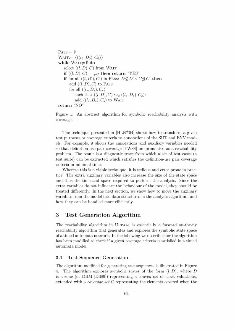
Pass:= ∅Wait:= {((l0,D0), C0)}while Wait 6= ∅ do
select ((l,D), C) from Wait
if ((l,D), C) |= ϕC then return “YES”if for all ((l,D′), C ′) in Pass: D 6⊆D′ ∨ C5 C ′ then
add ((l,D), C) to Pass
for all ((ls,Ds), Cs)such that ((l,D), C) ;c ((ls,Ds), Cs):add ((ls,Ds), Cs) to Wait
return “NO”
Figure 1: An abstract algorithm for symbolic reachability analysis withcoverage.
The technique presented in [HLN+04] shows how to transform a giventest purposes or coverage criteria to annotations of the SUT and ENV mod-els. For example, it shows the annotations and auxiliary variables neededso that definition-use pair coverage [FW88] be formulated as a reachabilityproblem. The result is a diagnostic trace from which a set of test cases (atest suite) can be extracted which satisfies the definition-use pair coveragecriteria in minimal time.
Whereas this is a viable technique, it is tedious and error prone in prac-tice. The extra auxiliary variables also increase the size of the state spaceand thus the time and space required to perform the analysis. Since theextra variables do not influence the behaviour of the model, they should betreated differently. In the next section, we show how to move the auxiliaryvariables from the model into data structures in the analysis algorithm, andhow they can be handled more efficiently.
3 Test Generation Algorithm
The reachability algorithm in Uppaal is essentially a forward on-the-flyreachability algorithm that generates and explores the symbolic state spaceof a timed automata network. In the following we describe how the algorithmhas been modified to check if a given coverage criteria is satisfied in a timedautomata model.
3.1 Test Sequence Generation
The algorithm modified for generating test sequences is illustrated in Figure4. The algorithm explores symbolic states of the form (l,D), where Dis a zone (or DBM [Dil89]) representing a convex set of clock valuations,extended with a coverage set C representing the elements covered when the
62

state is reached. We use (l,D) ; (l′,D′) to denote a transition in thesymbolic state space (see e.g. [BFH+01, LLPY97] for a description of thesymbolic semantics implemented in Uppaal). The algorithm terminateswhen the property ϕC is satisfied by a reached state. It is then possible tocompute a diagnostic trace starting in the inital state and showing how toreach a state satisfying ϕC (see e.g. [LPY95]).
The algorithm in Figure 4 is similar to the ordinary reachability algo-rithm used in Uppaal. The most significant modification is the addition ofa coverage set C to the symbolic states. The particular representation of acoverage set depends on the coverage criteria mentioned in ϕC . The currentimplementation allows for conjunctions of atomic coverage criteria of theform |Al| ∼ c, |Ae| ∼ c, or |xdu| ∼ c, where c ∈ N, ∼ ∈ {>,≥}, and |Al|and |Ae| denotes the number of covered locations and edges in automatonA respectively, and |xdu| the number of covered definition-use pairs of datavariable x.
In the algorithm, the coverage sets are initiated to C0 (line 2), checkedfor inclusion (“E” on line 6), and then successors are generated (line 9). Wedefine ((l,D), C) ;c ((ls,Ds), Cs) iff (l,D) ; (ls,Ds) and C is updated toCs as follows:
• location coverage (in case ϕc contains an atomic coverage criterion ofthe form |Al| ∼ c): Cs = C ∪ { ls}. In this case C0 = {l0} and C E C ′
iff C ⊆ C ′.
• edge coverage (in case ϕc contains an atomic coverage criterion of theform |Ae| ∼ c): Cs = C ∪ {e}, where e ∈ E is the edge from whichthe transition (l,D) ; (ls,Ds) is derived. In this case C0 = {} andC E C ′ iff C ⊆ C ′.
• definition-use pair coverage on variable x (in case ϕc contains anatomic coverage criterion of the form |xdu| ∼ c): In this case C =〈F,U〉, where F ∈ E ∪ {⊥}, and U is a coverage set of definition-usepairs of the form 〈ei, ej〉, where ei, ej ∈ E. We define Cs = 〈Fs, Us〉:
Fs =
{
e if x is defined on eF otherwise
Us =
{
U ∪ 〈F, e〉 if F 6=⊥ and x is used on eU otherwise
where e ∈ E is the edge from which the transition (l,D) ; (ls,Ds) isderived. Initially C0 = 〈⊥, {}〉 and 〈F,U〉 E 〈F ′, U ′〉 iff (F = F ′ ∧ U ⊆U ′).
Thus, to check for location coverage the coverage set C is simply storingthe set of locations that are visited when a symbolic state is reached. In a
63

network of timed automata, the update of C can easily be modified to checkfor coverage of a subset of the automata in the network. The case for edgecoverage is similar. Definition-use pair coverage is checked by keeping trackof active definitions in set F and covered DU-pairs in the set U .
Note how the coverage sets are checked for inclusion. Intuitively, the(symbolic) state ((l,D), C) does not need to be further examined if anotherstate ((l,D′), C ′) is reached that contains all time-assignments, i.e. D ⊆ D′,and covers the same or more elements, i.e. C E C ′. This means that stateswith smaller coverage will not be further explored which is the reason forallowing only checks of lower bounds of the size of the coverage sets. Theadvantage is of course that the number of explored states becomes smaller,leading to faster termination of the algorithm (see Section 5 for more details).
To check ((l,D), C) |= ϕC in the algorithm is straight-forward. Thevalue of |Al| or |Ae| is simply the number of elements in C. For definition-use pair coverage, where C is a pair of the form 〈F,U〉 the value of |xdu| isthe number of elements in the set U .
3.2 Test Suite Generation
In [HLN+04] we describe a technique for generating test suites (set of testsequences) covering a given test criterion. The idea is to annotate the modelwith edges allowing the model to reset to its initial state (an updating theauxiliary variables accordingly). We now describe how the algorithm shownin Figure 4 (and Figure 2 below) can be modified in a similar way.
Assume a predicate R ⊆ L × {0, 1} which is true for all automatonlocations that can be reset. In the algorithm, it suffices to insert the line
if R(l) then add ((l0,D0), C) to Wait
between line 8 and 9 of the algorithm of Figure 4. The case of definition-usepair coverage is the same except that F = {} to indicate that no activedefinitions have yet been reached from the initial location.
It should be obvious that the effect of adding the line corresponds toallowing the system to reset to its initial symbolic state (l0,D0) but withthe coverage collected before the reset. When Uppaal returns a diagnostictrace the output is interpreted as a set of traces separated by the resetoperations (which can be made visible in the diagnostic trace).
3.3 Time Optimal Test Suites
The standard reachability analysis algorithm implemented in Uppaal hasbeen extended to compute the trace with minimum time-delay satisfying agiven reachability property [BFH+01]. In the same way as described above,the algorithm for time-optimal reachability can be extended to computetime-optimal test sequences. The resulting abstract algorithm is shown in
64

Cost:= ∞Pass:= ∅Wait:= {((l0,D0), C0)}while Wait 6= ∅ do
select ((l,D), C) from Wait
if ((l,D), C) |= ϕC and min(D) < Cost
then Cost := min(D)if for all ((l,D′), C ′) in Pass: D′6vD ∨ C5C ′ then
add ((l,D), C) to Pass
for all ((ls,Ds), Cs)such that ((l,D), C) ;c ((ls,Ds), Cs):add ((ls,Ds), Cs) to Wait
return Cost
Figure 2: An abstract algorithm for symbolic time-optimal reachabilityanalysis with coverage.
Figure 2. It should be noticed that the DBMs D used in the algorithmfor time-optimal reachability is different from the one in ordinary symbolicreachability. For time-optimal reachability an extra clock is used that isnever reset. The minimum value of this clock is the minimum time it takesto reach the state. We will not discuss this in detail here, but refer thereader to [BFH+01] for more details.
In [BFH+01], it is also shown how the algorithm can be extended witha set of techniques inspired by branch and bound algorithms [AC91]. Someof these extensions can also be applied when generating time-optimal testsequences, but it remains to be investigated in detail.
4 Implementation
In the algorithm(s) described in the previous section, the symbolic statescontain a component representing the items covered in the path reachingthe state. In the case of definition-use pair coverage, it also contains moreinformation like the F set. In this section we will describe how the coveragesets have been implemented as bitvectors (in C++) in the algorithm.
We use bitvectors v ∈ {0, 1}n to implement a set C of n items, andassociate a natural number i to each item to be covered. Then v[i] = 1 ifitem i is in the set. This is exactly the standard bitvector representation ofsets. In order to improve efficiency, we use dynamic bitvectors and numberthe items as they are explored. For example, in the case of location coveragethe locations are numbered in the order they are explored by the algorithm,and the length of the bitvector grows as new locations are explored.
65

4.1 Overview
An overview of the implemented coverage module is shown in Figure 3. Thefunctionality of the module is to calculate (bitvector representation of) Qs
in a transition like ((l,D), Q) ;c ((ls,Ds), Qs). The input to the module isthe coverage set C, a symbolic transition, and the new symbolic state, i.e.; (ls,Ds). The example shown in the Figure 3 calculates Qs for locationcoverage of an automaton P1.
The module consists of three layers: the combined layer, the atomic layer,and the mapping table layer. The combined layer combines the coveragefrom the atomic terms and updates the set Q to Qs. The atomic layer usethe mapping tables to convert the coverage items found in the step to abitvector. The layers in the architecture are fixed, but the configuration ofthe atomic layer differs, depending on the atomic coverage criteria used inthe analysed property ϕc.
4.2 Layers
In general, the AllCoverage module consults one objects in the atomic layerfor each atomic coverage term found in ϕc. In the illustrated example, thereis only one atomic coverage — location coverage in automaton P1. Whenan object in the atomic layer is consulted it is given a symbolic transitionand a new state of the form ; (ls,Ds) and produces a bitvector δi with thebits set that correspond to items covered by the given transition and state.The successor set Qs is created by bitwise-or of the old set Q and δi for allatomic objects. Thus, in the general case Qs = Q ∪ (
⋃
i δi).
An object in the atomic layer is created for each atomic coverage de-scribed by the search property ϕc. In case of location or edge coverage it isinstantiated with the corresponding type location or edge, and an automatonA. In case of definition-use pair, the object is instantiated with the typedefinition-use and a variable name.
4.3 Dynamic Size of Bitvectors
The sets Q are saved with the symbolic state (l,D) as a bitvector that dy-namically increases in size when new items are explored. Since long bitvec-tors are more expensive to manipulate we avoid to associate bits with itemsthat have not yet been (or never will be) used. That is, the coverage itemsare numbered when they are first generated.
In the mapping table layer each coverage type has a table that associatesthe items with a unique bitnumber. To make the bitnumbers unique a globalcounter is used. The counter is incremented whenever a new item is found.In the example in Figure 3, the location is associated with the (bit)number2 and thus the bitvector “10” is generated.
66

Bit := 2..................................................................................................................................................................................................................................................................................................................................................................................................................................................................................................................................................................................................................................................................................................................................................................................................................................................
?
6
6
?
n atomic coverages
ls, P1
δ1 := 10..................................................................................................................................................................................................................................................................................................................................................................................................................................................................................................................................................................................................................................................................................................................................................................................................................................................
AllCoverage
Combined layer
Atomic layer
Mapping table
Location
Location table
1
; (ls, Ds)
Coverage P1
- -Cs := C ∪ δ1 ∪ · · · ∪ δnC, ; (ls, Ds)
Figure 3: Architecture of the coverage module. Location coverage exampleinstantiation.
5 Experiments
In order to evaluate the efficiency of the algorithm presented in this paper,we apply it to generate test suites from a model of protocol by Philips[BGK+96]. The protocol sends Manchester encoded bitstreams over a buslink, and detects collisions if two senders try to send that the same time-point. We use the model presented by Bengtsson et.al. in [BGK+96]. Themodel consists of seven timed automata. Four of the automata model thecomponents of the protocol: two sender automata (SA and SB) , a receiverautomaton R, and a wire automaton wire. Three of the automata model theenvironment of the protocol: two message automata providing the senderswith messages (messageA and messageB), and an automaton checking thecorrectness of the received messages (check).
Table 4 shows the time and space required to generate time-optimal testsuites with an coverage extended prototype version of Uppaal implementingthe algorithm described in Sections 3 and 4. The experiments have beenperformed on a Sun UltraSPARC-II 450MHz. Column “Pruned” gives thedata when using the algorithm presented in this paper. Column “Original”gives the data when using bitvectors but not the extra pruning possible dueto the monotonicity of the coverage sets (i.e. the effect of ⊆). For bothversions, we have used edge coverage criterion on two or three automata.We note that the reduction is 50 to 58% in time and 30 to 35% in memoryconsumption for this example.
67

Original Pruned
Coverage criteria Exec- Mem Exec- Memtime MB time MB
|Re| ∧ |SAe| 8.91 18.5 4.43 13.0
|Re| ∧ |SAe| ∧ |SBe| 14.61 25.5 6.06 16.5
Table 4: Measurements on Philips audio-control protocol with bus-collision.
6 Conclusion
In this paper, we have described how the real-time verification tool Uppaal
has been extended for test-case generation. In particular, we have extendedthe symbolic reachability analysis algorithm of the tool to generate tracessatisfying simple coverage criteria, which can be used as test sequences orsuites to test real-time systems.
The presented algorithm uses monotonically growing sets represented atbit-vectors to collect information about covered items. The monotonicity ofthese sets and the type of reachability properties checked for, allows for somepruning that normally can not be done. In our initial experiments, we havefound the gained reduction in time and space consumed by the algorithm tobe 50 to 58% and 30 to 35% respectively.
The current language for describing coverage criteria is very limited. Asfuture work we will develop a more generic language which is not limited toa predefined set of criteria. Another possible future direction of work is tointroduce monotonic variables in the modelling language of Uppaal. Suchvariables might be useful in specifications of other problem areas such ase.g. scheduling and other planing problems.
68

References
[AC91] D. Applegate and W. Cook. A Computational Study of theJob-Shop Scheduling Problem. OSRA Journal on Computing 3,pages 149–156, 1991.
[AD94] R. Alur and D. L. Dill. A theory of timed automata. TheoreticalComputer Science, 126(2):183–235, 1994.
[BFH+01] G. Behrmann, A. Fehnker, T. Hune, K. G. Larsen, P. Petters-son, and J. Romijn. Efficient Guiding Towards Cost-Optimalityin Uppaal. In T. Margaria and W. Yi, editors, Tools and Al-gorithms for the Construction and Analysis of Systems : 7th In-ternational Conference, (TACAS’01), number 2031 in LectureNotes in Computer Science, pages 174–188. Springer–Verlag,2001.
[BGK+96] J. Bengtsson, W.O. David Griffioen, K. J. Kristoffersen, K. G.Larsen, F. Larsson, P. Pettersson, and W. Yi. Verification of anAudio Protocol with Bus Collision Using Uppaal. In R. Alurand T. A. Henzinger, editors, Proc. 8th Int. Conf. on ComputerAided Verification, volume 1102 of Lecture Notes in ComputerScience, pages 244–256. Springer–Verlag, 1996.
[Dil89] D. Dill. Timing Assumptions and Verification of Finite-StateConcurrent Systems. In J. Sifakis, editor, Proc. of AutomaticVerification Methods for Finite State Systems, volume 407 ofLecture Notes in Computer Science, pages 197–212. Springer–Verlag, 1989.
[FW88] P. G. Frankl and E. J. Weyuker. An applicable family of dataflow testing criteria. IEEE Trans. Softw. Eng., 14(10):1483–1498,1988.
[HLN+04] A. Hessel, K. G. Larsen, B. Nielsen, P. Pettersson, and A. Skou.Time-Optimal Real-Time Test Case Generation using Uppaal.In A. Petrenko and A. Ulrich, editors, Proc. 3rd InternationalWorkshop on Formal Approaches to Testing of Software 2003(FATES’03), volume 2931 of Lecture Notes in Computer Science,pages 136–151. Springer–Verlag, 2004.
[LLPY97] F. Larsson, K. G. Larsen, P. Pettersson, and W. Yi. EfficientVerification of Real-Time Systems: Compact Data Structuresand State-Space Reduction. In 18th IEEE Real-Time SystemsSymposium (RTSS’97), pages 14–24. IEEE Computer SocietyPress, 1997.
69

[LPY95] K. G. Larsen, P. Pettersson, and W. Yi. Diagnostic Model-Checking for Real-Time Systems. In Proc. of Workshop onVerification and Control of Hybrid Systems III, volume 1066 ofLecture Notes in Computer Science, pages 575–586. Springer–Verlag, 1995.
[LPY97] K. G. Larsen, P. Pettersson, and W. Yi. Uppaal in a Nutshell.Int. Journal on Software Tools for Technology Transfer, 1(1–2):134–152, October 1997.
[SVD01] J. Springintveld, F. Vaandrager, and P.R. D’Argenio. TestingTimed Automata. Theoretical Computer Science, 254(1-2):225–257, March 2001.
70

Paper C
Johan Blom, Anders Hessel, Bengt Jonsson, and Paul Pettersson Specifyingand Generating Test Cases Using Observer Automata. In J. Gabowski andB. Nielsen, editors, Proceedings of the 4th International Workshop on For-mal Approaches to Testing of Software 2004 (FATES’04), volume 3395 inLecture Notes in Computer Science, pages 125–139, Springer–Verlag BerlinHeidelberg 2005.


Specifying and Generating Test Cases Using Ob-
server Automata
Johan Blom, Anders Hessel, Bengt Jonsson, and Paul PetterssonDepartment of Information Technology, Uppsala University,
P.O. Box 337, SE-751 05 Uppsala Sweden Email:
{johan,hessel,bengt,paupet}@it.uu.se.
Abstract We present a technique for specifying coverage criteria anda method for generating test suites for systems whose behaviours canbe described as extended finite state machines (EFSM). To specifycoverage criteria we use observer automata with parameters, whichmonitor and accept traces that cover a given test criterion of an EFSM.The flexibility of the technique is demonstrated by specifying a numberof well-known coverage criteria based on control- and data-flow infor-mation using observer automata with parameters. We also developa method for generating test cases from coverage criteria specified asobservers. It is based on transforming a given observer automata intoa bitvector analysis problem that can be efficiently implemented as anextension to an existing state-space exploration such as, e.g. SPIN orUppaal.
1 Introduction
Model based test case generation has in recent years been developed as aprominent technique in testing of reactive software systems. A model servesboth the purpose of specifying how the system should respond to inputs fromits environment, and of guiding the selection of test cases, e.g., using suitablecoverage criteria. Typical notations for such models are state machines insome form, often extended with data variables. Test cases can be selectedas individual “executions” of the model, checking that the outputs from thesystem under test (SUT) conform to those specified by the model.
There is a large literature and several tools (e.g., [dZ99, LBV02, SEG+98,MA00, dBRS+00]) for generation of test cases from extended state machinemodels (EFSMs). In typical approaches, the selection of test cases followssome particular coverage criterion, such as coverage of control states, edges,etc., or using an explicitly given set of test purposes [FJJV97, RdBJ00].When the model contains data variables, constraint solving techniques canbe used to find actual values of input parameters that drive the executionin a desired direction [LBV02, NS03, Meu00].
Since different coverage criteria are suitable in different situations, andsatisfy different constraints on fault detection capability, cost, informationabout where potential faults may be located, etc., it is highly desirable that
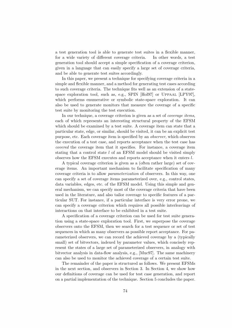
a test generation tool is able to generate test suites in a flexible manner,for a wide variety of different coverage criteria. In other words, a testgeneration tool should accept a simple specification of a coverage criterion,given in a language that can easily specify a large set of coverage criteria,and be able to generate test suites accordingly.
In this paper, we present a technique for specifying coverage criteria in asimple and flexible manner, and a method for generating test cases accordingto such coverage criteria. The technique fits well as an extension of a state-space exploration tool, such as, e.g., SPIN [Hol97] or Uppaal [LPY97],which performs enumerative or symbolic state-space exploration. It canalso be used to generate monitors that measure the coverage of a specifictest suite by monitoring the test execution.
In our technique, a coverage criterion is given as a set of coverage items,each of which represents an interesting structural property of the EFSMwhich should be examined by a test suite. A coverage item can state that aparticular state, edge, or similar, should be visited, it can be an explicit testpurpose, etc. Each coverage item is specified by an observer, which observesthe execution of a test case, and reports acceptance when the test case hascovered the coverage item that it specifies. For instance, a coverage itemstating that a control state l of an EFSM model should be visited simplyobserves how the EFSM executes and reports acceptance when it enters l.
A typical coverage criterion is given as a (often rather large) set of cov-erage items. An important mechanism to facilitate specification of manycoverage criteria is to allow parameterization of observers. In this way, onecan specify a set of coverage items parameterized over, e.g., control states,data variables, edges, etc. of the EFSM model. Using this simple and gen-eral mechanism, we can specify most of the coverage criteria that have beenused in the literature, and also tailor coverage to specific features of a par-ticular SUT. For instance, if a particular interface is very error prone, wecan specify a coverage criterion which requires all possible interleavings ofinteractions on that interface to be exhibited in a test suite.
A specification of a coverage criterion can be used for test suite genera-tion using a state-space exploration tool. First, we superpose the coverageobservers onto the EFSM, then we search for a test sequence or set of testsequences in which as many observers as possible report acceptance. For pa-rameterized observers, we can record the achieved coverage by a (typicallysmall) set of bitvectors, indexed by parameter values, which concisely rep-resent the states of a large set of parameterized observers, in analogy withbitvector analysis in data-flow analysis, e.g., [Muc97]. The same machinerycan also be used to monitor the achieved coverage of a certain test suite.
The remainder of the paper is structured as follows. We present EFSMsin the next section, and observers in Section 3. In Section 4, we show howour definitions of coverage can be used for test case generation, and reporton a partial implementation of the technique. Section 5 concludes the paper.
74

Related Work. Most related work on test case generation from mod-els of reactive systems employ some rather specific selection of coveragecriteria. Explicitly given test purposes have been considered, both enumer-ative [FJJV97] and symbolic [RdBJ00]. Test purposes in these works can insome sense be regarded as coverage observers, but are not used to specifymore generic coverage criteria and do not make us of parameterization, asin our work. For finite-state machines and EFSMs, several approaches focuson particular coverage criteria, e.g., Bouquet and Legeard [BL03] synthe-size test cases corresponding to combinations of choices of control flow andboundary values of state variables, Nielsen and Skou [NS03] generate testcases that cover reachable symbolic states. These coverage criteria can bespecified as observers in our framework.
Some approaches present more flexible techniques for specifying a varietyof coverage criteria. Hong et al [HLSU02, HCL+03] describe how flow-basedcoverage criteria can be expressed in temporal logic. A particular coverageitem is expressed in CTL, and a model checker generates a trace which cov-ers the coverage item. In our approach, we use observers instead of temporallogic, which avoids some of the limitations of temporal logic [Wol81]. Fried-man et al [FHNS02] specifies coverage by giving a set of projections of thestate space (e.g., on individual state variables, components of control flow)that should be covered, possibly under some restrictions. Our approach gen-eralizes this one, by allowing to define observers. Also, we can let one passof a state-space exploration tool generate a test suite that covers a large setof coverage items, whereas the above approaches invoke a run of a modelchecker for each coverage item.
Constraint Logic Programming for model based test case generation hasbeen used, e.g., by Marre and Arnould [MA00], by Meudec [Meu00], byPretschner et al. [Pre01]. These approaches typically compile the specifica-tion into a constraint logic programming language, in which test cases canbe extracted using symbolic execution.
2 Extended Finite State Machines
We assume that the specification of a module to be tested is given as anextended finite state machine in some syntax. In this section, we presenta generic way to describe EFSMs, but our work can be adapted to morespecific EFSM notations such as, e.g., UML Statecharts [GLM02] or SDL[ITU99].
We assume that a System Under Test (SUT) interacts with its environ-ment through events. Whenever the SUT receives an input event, it respondsby performing some local computation and emitting an output event. Toa given SUT, we associate a set A of event types, each with a fixed arity.An event is a term of form a(d1, . . . , dk) where a is an event type of arity k
75

and d1, . . . , dk are the parameters of the event. The set A of event types ispartitioned into input event types and output event types. A trace is a finitesequence
a1(d1)/b1(d′1) a2(d2)/b2(d
′2) · · · an(dn)/bn(d
′n)
of input/output event pairs. Intuitively, the trace represents a behaviorwhere the SUT, starting from its initial state, receives the input event,a1(d1) and responds with the output event b1(d
′1). Thereafter, it receives
the input event a2(d2) and so on. An input sequence is a finite sequence ofinput events.
Assume a set AI of input event types, and a set AO of output eventtypes. An Extended Finite State Machine (EFSM) over (AI , AO) is a tuple〈L, l0, v, E〉 where
• L is a finite set of locations (aka control states).
• l0 ∈ L is the initial location.
• v is a finite set of state variables.
• E is a finite set of edges, each of which is of form
e : l l′-a(w), g → u := expr/b(expr ′)
where
– e is the name of the edge,
– l is the source location, and l′ is the target location,
– a ∈ AI is an input event type, and w is a tuple of formal para-meters of a,
– g is a guard,
– u := expr is an assignment of new values to a subset u ⊆ v of thestate variables, and
– b(expr ′) is an expression which evaluates to an output event.
g, expr, and expr′ may depend on the formal parameters w of theinput event and the state variables v.
Intuitively, an edge of the above form denotes that whenever the EFSM isin location l and receives an event of form a(w), then, provided that theguard g is satisfied, it can perform a computation step in which it updatesits state variables by u := expr, emits the output event b(expr ′) and movesto location l′. We require the EFSM to be deterministic, i.e., that for anytwo edges with the same source location l and parameterized input eventa(w), the corresponding guards are inconsistent.
76

USER
(ii)
coffee()
display()
make()
done()
insert(x)
show(m)
BrewerController
(i)
e5:display()→show(m)
e3:done()→
BUSYIDLE
e4:display()→show(m)
e2:coffee(),m>0→make(),m := m − 1
e1:insert(x), x+m≤5 → m := m + x
Figure 1: An EFSM specifying the controller of a simple coffee machine.
A system state is a tuple 〈l, σ〉 where l is a location, and σ is a mappingfrom v to values. We can extend σ to a partial mapping from expressionsover v in the standard way. The initial system state is the tuple 〈l0, σ0〉 wherel0 is the initial location, and σ0 gives a default value to each state variable.
A computation step is of the form 〈l, σ〉a(d)/b(d
′)
−→ 〈l′, σ′〉 consisting of system
states 〈l, σ〉 and 〈l′, σ′〉, an input event a(d), and an output event b(d′), such
that there is an edge of the (above) form l
a(w),g→u:=expr/b(expr ′)-
l′, for which
σ(g[d/w]) is true, σ′ = σ[u 7→ σ(expr[d/w])], and d′= σ(expr′[d/w]). A run
of the EFSM over a trace a1(d1)/b1(d′1) · · · an(dn)/bn(d
′n) is a sequence of
computation steps
〈l0, σ0〉a1(d1)/b1(d
′1)
−→ 〈l1, σ1〉a2(d2)/b2(d
′2)−→ · · ·
an(dn)/bn(d′n)
−→ 〈ln, σn〉
labelled by the input-output event pairs of the trace.
Example 1 In Figure 1 an EFSM (from [HLSU02]) specifying the behaviorof the controller of a simple coffee machine which interacts with a user and abrewer unit is shown. The controller has L = {IDLE ,BUSY }, l0 = IDLE,v = {m}, AI = {insert , coffee , display , done}, AO = {show ,make}, andE = {e1, e2, e3, e4, e5}. The parameter x and the variable m take values thatare integers in the range [0 . . . 5].
An EFSM can be used to check that a trace of a SUT conforms toits specification, by checking that each output event produced by the SUTconforms to the corresponding output event prescribed in the EFSM. For testgeneration, the output events will not be significant, and we will thereforeomit them in the rest of the paper, thus writing an edge of an EFSM as
l
a(w),g→u:=expr-
l′. We can also consider specifications that are parallelcompositions of EFSMs, but omit such a treatment in this version of thepaper.
77

3 Observers
In this section, we present how to use observers to specify coverage criteriafor test generation or test monitoring. A coverage criterion typically consistsof a (long) list of items that should be “covered” or “visited”. For instance,the criterion of “full location coverage” stipulates that a test suite shouldvisit all locations of a given EFSM. We will use the term coverage item foran item that should be “covered” or “visited”. Letting a test sequence berepresented as a trace, we can use standard techniques from model-checkingand run-time verification [VW86, HR02] to represent a coverage item byan observer, which monitors a trace and “accepts” whenever the coverageitem has been covered. An observer observes how an EFSM executes a runover a trace, and “remembers” some chosen aspects of the EFSM execution.The observer can observe the events of the trace, as well as syntacticalcomponents of edges that the EFSM traverses in response to observed events,but should not interfere with the execution of the system.
Typical coverage criteria consist not only of a single coverage item, butof a large set of coverage items. We therefore extend the notion of observersby a parameterization mechanism so that they can specify a set of coverageitems. Parameterized observers are simply observers, in which locations andedges may be parameterized by parameters that range over given domains.Each choice of parameter values gives a certain observer location or edge.For each specified coverage item, the observer has an accepting (possiblyparameterized) location which (for convenience) we give the name of thecorresponding coverage item. When the accepting location is entered, thetrace has covered the corresponding coverage item.
As a very simple example, the coverage item “visit location l of theEFSM” can be represented by an observer with one initial state, and oneaccepting location, named loc(l), which is entered when the EFSM enterslocation l. The coverage criterion “visit all locations of the EFSM” canbe represented by a parameterized observer with one initial state, and oneparameterized accepting location, named loc(L), where L is a parameter thatranges over locations in the EFSM. For each value l of L, the location loc(l)is entered when the EFSM enters location l.
Formally, an observer is a tuple (Q, q0, Qf , B) where
• Q is a finite set of observer locations
• q0 is the initial observer location.
• Qf ⊆ Q is a set of accepting observer locations, whose names are thecorresponding coverage items.
• B is a set of edges, each of form
78

q q′-b
where b is a predicate that can depend on the input event received bythe SUT, the mapping from state variables of EFSM to their valuesafter performing the current computation step, and the edge in theEFSM that is executed in response to the current input event.
Intuitively, at any specific instant during test execution the observer is in oneof its locations, q say. At each occurrence of an event, the observer traversesan outgoing edge from q, whose predicate is satisfied for this event, and thecorresponding transition performed by the EFSM. Note that, in contrastto EFSMs, observers may be non-deterministic, since a coverage item ingeneral can be covered in several ways.
In many cases, the initial location q0 has an edge to itself with thepredicate true. We use the symbol • to represent q0 together with such aself-loop. Similarly, we assume that each qf ∈ Qf has an edge to itself withthe predicate true. We use the symbol } to represent accepting locations. Insection 3.2, we discuss the effect of these self-loops in more detail. Intuitively,the one in q0 is often used to allow the observer to non-deterministically startmonitoring at any point of an EFSM run. The loop in each qf is used toallow an observer to stay in an accepting location.
In order for observers to specify coverage criteria consisting of severalcoverage items, we allow locations and edges to be parameterized. Eachparameter has a finite domain, which could be the set of EFSM locations,edges, state variables, or similar. We use uppercase letters in typewriterfont for parameters. A parameterized location represents the collection oflocations obtained by instantiating its parameters, and similarly for edges.
3.1 Observer Predicates
In the following we introduce a more specific syntax for the predicates boccurring on observer edges. The predicates will use a set of predefinedmatch variables that are given values at the occurrence of
• an event a(d),
• an edge e : l
a(w),g→u:=expr-
l′ of the EFSM, traversed in response toa(d),
• the computation step 〈l, σ〉a(d)−→ 〈l′, σ′〉 generated in response to a(d).
For a traversed EFSM edge we use the following match variables (with as-sociated meaning):
79

event type is the event type a of the occurring event
event-pars is the list d of parameters of the eventedge is the name etarget loc is the target location l′
guard is the guard expression gassignments is the set u := expr of assignmentstarget val is the function from EFSM state variables to values, s.t. val(u)
is the value σ′(u) of variable u just after the computation step.
Similarly, we also define source loc for the source location and source valfor the value σ(u) of variable u just before the computation step. To be ableto express more interesting properties we also introduce a set of operationsthat can be used together with the match variables:
• lhs is a function to get the left hand side expression of an assignment.A left hand side expressions is always assumed to be a variable.
• rhs is a function to get the right hand side expressions of an assign-ment. The right hand side expression, expr, uses the vocabulary de-fined for the EFSM specification.
• vars is a function such that vars(Exp) returns a set with all variablesfound in Exp. Exp is a set that contains the result of applying rhs toeach assignment in assignments, or a guard expression.
• affect is a function such that affect(A,V ar1, V ar2) returns the assign-ment it is being applied to, A, if V ar1 ∈ vars(rhs(A))∧V ar2 = lhs(A)otherwise the empty set is returned.
• map is a function such that map(Fun, Set) applies the function, Funon each element in the set Set and returns the set of the results.
With the match variables and operations above we define new functions thatcan be used as tests in the observer. In this paper, we shall make use of:
• def (v), which is true iff the variable v is defined by the transition inthe EFSM. This can be expressed as:
v ∈ map(lhs, assignments)
• use(v), which is true iff the variable v is used (in a guard or assignment)by the transition in the EFSM. This can be expressed as:
v ∈ vars(map(rhs, assignments)) ∨ v ∈ vars(guard)
• da(v1, v2), which is true iff the variable v1 is on the right hand sideand variable v2 is on the left hand side of the same assignment in the
80

(i) (ii) (iii)
l0
l1
l2
c(),x=tt ∧ y=tt →
a()→ x:=tt
e0:
e2:
e1:b(),y=ff → y:=tt
def(Z) ∧ edge = E
¬ def(Z)
use(Z) ∧ edge = E′
du(Z, E, E′)
q0
q1(Z, E)¬ def(x)
q0
q1(x , e1 )
du(x , e1 , e2 )
def(x) ∧ edge = e1
use(x) ∧ edge = e2
Figure 2: Examples of (i) observer monitoring definition (on edge e1) anduse (on edge e2) of variable x, (ii) a parameterized observer, and (iii) asimple EFSM.
EFSM specification. The function can intuitively be understood to betrue if v1 directly affects v2. This can be expressed as:
map(affect(v1, v2), assignments) 6= ∅
Example 2 The (non-parameterized) observer in Figure 2(i) specifies def-inition-use pair coverage for a specific variable m, and specific edges e1
and e2 . Figure 2(ii) shows a corresponding (parameterized) observer thatspecifies definition-use pair coverage for any EFSM variable Z, and EFSMedges E and E′. This is done by parameterizing the location q1 with anyvariable and any edge, and the accepting location du with any variable andany two edges. The edges are parameterized in a similar way. For example,there is one observer edge from location q1(z, e) to location du(z, e, e′) foreach EFSM variable z, and each pair e, e′ of EFSM edges.
3.2 How Observers Monitor Coverage Criteria
In test case generation or when monitoring test execution of a SUT, anobserver observes the events of the SUT, and the computation steps of theEFSM. Reached accepting locations correspond to covered coverage items.We formally define the execution of an observer in terms of a compositionbetween an EFSM and an observer, which has the form of a superpositionof the observer onto the EFSM. Each state of this superposition consistsof a state of the EFSM, together with a set of currently occupied observerlocations.
Say that a predicate b on an observer edge is satisfied by a computation
step 〈l, σ〉a(d)−→ 〈l′, σ′〉 of an EFSM, denoted 〈l, σ〉
a(d)−→ 〈l′, σ′〉 |= b if b holds
81

for the event a(d), the computation step 〈l, σ〉a(d)−→ 〈l′, σ′〉, and the edge
e : l
a(w),g→u:=expr-
l′ from which the computation step is derived.Formally, the superposition of an observer (Q, q0, Qf , B) onto an EFSM
〈L, l0, v, E〉 is defined as follows.
• States are of the form 〈〈l, σ〉 ‖ Q〉, where 〈l, σ〉 is a state of the EFSM,and Q is a set of locations of the observer.
• The initial state is the tuple 〈〈l0, σ0〉 ‖ {q0}〉, where 〈l0, σ0〉 is theinitial state of the EFSM, and q0 is the initial location of the observer.
• A computation step is a triple 〈〈l, σ〉 ‖ Q〉a(d); 〈〈l′, σ′〉 ‖ Q′〉 such that
〈l, σ〉a(d)−→ 〈l′, σ′〉 and
Q′ =
{
q′ | qb
−→ q′ and q ∈ Q and 〈l, σ〉a(d)−→ 〈l′, σ′〉 |= b
}
• A state 〈〈l, σ〉 ‖ Q〉 of the superposition covers the coverage itemrepresented by the location qf ∈ Qf if qf ∈ Q.
Note that the way the set Q is updated essentially results in an (on-the-fly) subset construction of the parameterised observer. Initially, Q containsonly the initial observer location q0. In the subsequent computation steps,Q contains the set of all occupied observer locations, representing alreadycovered and partially covered coverage items. In each computation step, theset of occupied observer locations Q′ is obtained by generating all possiblesuccessors to the locations in Q, i.e. all q′ such that there exists a q ∈ Q and
an edge qb
−→ q′ ∈ B with b satisfied by the computation step of the EFSM.Recall that both the initial and all accepting observer locations have
implicit self-loops with predicate true. This means that in the superpositionof the observer onto an EFSM, the initial observer location q0 is alwaysoccupied and all reached accepting observer locations (representing coveredcoverage items) are guaranteed to remain in Q. The fact that q0 is alwaysoccupied can be intuitively understood as allowing for the observer to non-deterministically start monitoring an EFSM (or a SUT) at any computationstep of an run (or at any point during test execution).
Example 3 If the observer in Figure 2(ii) is superposed onto the EFSM inFigure 2(iii), the following computation steps can be taken 〈〈l0, {x=ff, y=
ff}〉 ‖ {q0}〉a(); 〈〈l1, {x=tt, y=ff}〉 ‖ {q0, q1(x , e0 )}〉
b(); 〈〈l0, {x=tt, y=tt}〉 ‖
{q0, q1(x , e0 ), q1(y , e1 )}〉a(); 〈〈l1, {x = tt, y = tt}〉 ‖ {q0, q1(x , e0 ), q1(y , e1 )}〉
c(); 〈〈l2, {x=tt, y=tt}〉 ‖ {q0, q1(x , e0 ), q1(y , e1 ), du(x , e0 , e2 ), du(y , e1 , e2 )}〉.Thus, the two possible definition-use pairs are covered.
82

target loc=L
(iv)
(i)
loc(L)
q0
q1(X, E)
def (X) ∧ edge=E
¬def (X)
use(X)
all def (E)
(ii)
du(X, E, E′)
affect pair(X, E, Z, E′)
q0
edge cov(E)
edge=E
q1(X, E)
use(X) ∧ edge=E′
q0
¬def (X)
(iii)
def (X) ∧ edge=E
(v)
q0
q1(X, Y, E)
da(X, Y) ∧ edge=E
da(Y, Z) ∧ edge=E′
q0
q0
(vii)
¬def (Y)
q0
loc var(L, V)
(vi)
event var(V)
target loc=L∧ event=insert(V)target val(m)=V
Figure 3: Seven examples of coverage criteria expressed as observers.
3.3 Examples of Observers
Figure 3 shows observers specifying a number of coverage criteria describedin the literature [CPRZ89].
The all-locations coverage criteria is specified by the observer shown inFigure 3(i), where the parameter L is any location in an EFSM. If theobserver is superposed onto the EFSM of Figure 1, we have that L ={IDLE ,BUSY } and the edge of the parameterized observer represents twoedges, one guarded by target loc = IDLE with target location loc(IDLE )target loc(BUSY ), and the other guarded by target loc = BUSY withtarget location loc(BUSY ). The set of possible coverage items is thus{loc(IDLE ), loc(BUSY )}.
The all-edges coverage observer in Figure 3(ii) is similar to the all-location coverage observer. The edges of the EFSM in Figure 1 is E={e1 , . . . , e5},and thus the set of possible coverage items when the observer is superposedonto the EFSM is {edge cov(ei) | ei ∈ E }.
The all-definition use-pairs (all-uses [CPRZ89]) coverage observer in Fig-
83

ure 3(iii) has an accepting location du(X, E, E′), where X is a variable name,E is an edge on which X is defined, and E′ an edge on which X is used.Variable X may not be redefined in the trace between E and E′. If theobserver is superposed onto the EFSM the complete set of coverage itemsis {du(m, e1 , e1 ), du(m, e1 , e2 ), du(m, e1 , e4 ), du(m, e2 , e1 ), du(m, e2 , e2 ),du(m, e2 , e4 ), du(m, e2 , e5 )}. The definition-use pair du(m, e1 , e5 ) can notbe covered since m is always redefined on edge e2 in between e1 and e5 .
The all-definitions coverage observer of Figure 3(iv) is similar to the all-definition use-pairs coverage except that only the defining edges are requiredto be covered. When the observer is superposed with the EFSM in Figure 1the set of accepting locations is {all def (e1 ), all def (e2 )}.
The all affect-pairs (Nafos’ required k-Tuples [CPRZ89]) coverage ob-server shown in Figure 3(v) accepts whenever a variable x affects a variablez via another variable y . In this case we require that x directly affectsy which, without redefinition, directly affects z . No such affect pairs arepossible in the EFSM of Figure 1.
The context coverage criteria observer in Figure 3(vi) covers all values ofa given variable m. We use target val(m), to denote the value of m at thetarget EFSM-state. The observer has an accepting location loc var(L, V),where V is the value domain of variable m. E.g. loc var (IDLE , 0) andloc var(BUSY , 1) are accepting locations. The observer in Figure 3(vii)is similar, but covers the possible values the event parameter at transitionslabelled with the event insert(x ).
4 Test Case Generation
4.1 Algorithms
At test case generation, we use the superposition of an observer onto anEFSM, and views the test case generation problem as a search explorationproblem. To cover a coverage item qf is then the problem of finding a trace
tr = 〈〈l0, σ0〉 ‖ {q0}〉a(d); . . .
a′(d′)
; 〈〈l, σ〉 ‖ Q〉 such that qf ∈ Q
We will use ω(tr) = a(d) . . . a′(d′) to denote the word of the trace tr, or just
ω whenever tr is clear from the context. In general, a single trace tr maycover several accepting locations of the observer. We say that the trace trcovers n accepting observer states if there are n accepting states in Q, andwe use |Qf ∩ Q| to denote the number of accepting states in Q.
We are now ready to present the test case generation algorithm. We shalllimit the presentation to an algorithm generating a single trace. The sametechnique can be used to produce sets of traces to cover many coverage items.Alternatively, the EFSM model can be annotated with edges that reset the
84

Pass:= ∅, Max := 0, ωmax := ω0
Wait:= {〈〈s0 ‖ {q0}〉, ω0〉}while Wait 6= ∅ do
select 〈〈s ‖ Q〉, ω〉 from Wait
if |Qf ∩ Q| > Max then
ωmax := ω, Max := |Qf ∩ Q|if for all 〈s ‖ Q′〉 in Pass: Q 6⊆ Q′ then
add 〈s ‖ Q〉 to Pass
for all 〈s′′ ‖ Q′′〉
such that 〈s ‖ Q〉a; 〈s′′ ‖ Q′′〉:
add 〈〈s′′ ‖ Q′′〉, ωa 〉 to Wait
return ωmax and Max
Figure 4: An abstract breadth-first search exploration algorithm for testcase generation.
EFSM to its initial state. A generated trace can then be interpreted as aset of test cases separated by the reset edges [HLN+04].
An abstract algorithm to compute test case is shown in Figure 4. Toimprove the presentation, we use s to denote a system of the form 〈l, σ〉, s0
to denote the initial system state 〈l0, σ0〉, and a to denote an input actiona(d). The algorithm computes the maximum number of coverage items thatcan be visited (Max), and returns a trace with maximum coverage (ωmax).The two main data structures Wait and Pass are used to keep track of thestates waiting to be explored, and the states already explored, respectively.
Initially, the set of already explored states is empty and the only statewaiting to be explored is the extended state 〈〈s0 ‖ {q0}〉, ω0〉, where ω0 isthe empty trace. The algorithm then repeatedly examines extended statesfrom Wait. If a state 〈s ‖ Q〉 found in Wait is included in a state 〈s ‖ Q′〉in Pass, then obviously 〈s ‖ Q〉 does not need to be further examined. Ifnot, all successor states reachable from 〈s ‖ Q〉 in one computation stepare put on Wait, with their traces extended with the input action of thecomputation step from which they are generated. The state 〈s ‖ Q〉 is savedin Pass. The algorithm terminates when Wait is empty
The variables ωmax and Max are initially set to the empty trace and0, respectively. They are updated whenever an extended state is found inWait which covers a higher number of coverage items than the current valueof Max. Throughout the execution of the algorithm, the value of Max isthe maximum number of coverage items that have been covered by a singletrace, and ωmax is one such trace. When the algorithm terminates, the twovalues Max and ωmax are returned.
85

4.2 Bitvector Implementation
In order to efficiently represent and manipulate the set Q of observer loca-tions we shall use bitvector analysis [KSV96]. Let the set Q be representedby a bitvector where each bit represents an observer location q′. Then eachbit is updated by the following function
fq′(q′) =
∨
〈b,q〉∈ in(q′)
q ∧ b
where in(q′) = { 〈b, q〉 | qb
−→ q′ ∈ B } is the set of pairs of predicates band source locations q of the edges ingoing to the location q′. That is, given
a state of the superposition 〈〈l, σ〉 ‖ Q〉 and an EFSM-transition 〈l, σ〉a(d)−→
〈l′, σ′〉 the bit representing q′ is set to 1 if there is an observer edge qb
−→ q′ ∈
B, such that q ∈ Q and 〈l, σ〉a(d)−→ 〈l′, σ′〉 |= b. Otherwise the bit representing
q′ is set to 0. It should be obvious that this corresponds precisely to thesemantics of an observer superposed onto an EFSM, described in Section 3.2.
Example 4 When the observer in Figure 2(ii) is superposed onto the EFSMin Figure 2(iii), we have E = E′ = E = {e0 , e1 , e2} and Z = v = {x , y}.Thus, we have that
Q ={
q0
}
∪{
q1(z, ea) | z∈ v ∧ ea∈E}
∪{
du(z, ea, eb) | z∈ v ∧ ea, eb ∈ E}
Any enumeration of the set can be used as index in the bitvector. As theobserver has three locations with parameters we get three types of bitvectorfunctions:
fq0(q0) = q0 ∧ tt (1)
fq1(vi ,ej )(q1(vi , ej )) = ( q0 ∧ def (vi) ∧ (edge = ej ) ) ∨
( q1(vi , ej ) ∧ ¬def (vi) ) (2)
fdu(vi ,ej ,ek )(du(vi , ej , ek )) = ( q1(vi , ej ) ∧ use(vi) ∧ (edge = ek ) ) ∨
( du(vi , ej , ek ) ∧ tt ) (3)
There is one function of type (1), six of type (2), and 18 of type (3). Notethat (1) is always true and that (3) will remain true once it becomes true,due to implicit self-loops in these locations.
4.3 Implementation Efforts
Some of the techniques presented in this paper have been implemented in aprototype version of the model-checking tool Uppaal [LPY97], extended fortest case generation [HP04]. The current implementation uses the bitvectorimplementation described above, but is limited to a number of predefined
86

coverage criteria. For a given coverage criteria (a set of) test cases can begenerated from system specifications described as DIEOU-timed automata[HLN+04]. We are currently in progress with a larger case-study in collab-oration with Ericsson where this tool will be applied.
We are also developing a tool operating on a subset of the functionallanguage Erlang, also using the techniques presented in this paper. Thetool will be applied in a case-study in collaboration with Mobile Arts.
5 Conclusions
We have presented a technique for specifying coverage criteria in a simpleand flexible manner using observer automata with parameters. Observershave shown to be a flexible tool in model checking and run-time monitoring,and by this paper we have shown that they are a versatile tool for specifyingcoverage criteria for test case generation and test monitoring. In particularthe parameterization mechanism, as used in this paper, allows a succinctspecification of several standard generic coverage criteria. In this way, testcase generation can be transformed into a reachability problem, which canbe attacked by a standard state-space reachability tool.
In previous works, we have implemented special cases of this test casegeneration technique, using Uppaal, indicating that the approach is practi-cal. We are currently working on a general implementation of the observerconcept, and plan to apply it in a larger case study.
87

References
[BL03] F. Bouquet and B. Legeard. Reification of executable test scriptsin formal specification-based test generation: The java cardtransaction mechanism case study. In FME 2003, volume 2805of Lecture Notes in Computer Science, pages 778–795. Springer–Verlag, 2003.
[CPRZ89] L. A. Clarke, A. Podgurski, D. J. Richardsson, and Steven J.Zeil. A formal evaluation of data flow path selection criteria.IEEE Trans. on Software Engineering, SE-15(11):1318–1332,November 1989.
[dBRS+00] L. du Bousquet, S. Ramangalahy, S. Simon, C. Viho, A. Belin-fante, and R.G. de Vries. Formal test automation: The con-ference protocol with tgv/torx. In H. Ural, R.L. Probert, andG. von Bochmann, editors, IFIP 13th Int. Conference on Testingof Communicating Systems(TestCom 2000). Kluwer AcademicPublishers, 2000.
[dZ99] L. du Bousquet and N. Zuanon. An overview of Lutess, aspecification-based tool for testing synchronous software. InProc. 14th IEEE Intl. Conf. on Automated SW Engineering, Oc-tober 1999.
[FHNS02] G. Friedman, A. Hartman, K. Nagin, and T. Shiran. Projectedstate machine coverage for software testing. In Proc. ACM SIG-SOFT International Symposium on Software Testing and Analy-sis, pages 134–143, 2002.
[FJJV97] J.-C. Fernandez, C. Jard, T. Jeron, and C. Viho. An experi-ment in automatic generation of test suites for protocols withverification technology. Science of Computer Programming, 29,1997.
[GLM02] S. Gnesi, D. Latella, and M. Massink. Modular semantics fora UML statechart diagrams kernel and its extension to multi-charts and branching time model-checking. Journal of Logic andAlgebraic Programming, 51(1):43–75, 2002.
[HCL+03] H.S. Hong, S.D. Cha, I. Lee, O. Sokolsky, and H. Ural. Dataflow testing as model checking. In ICSE’03: 25th Int. Conf. onSoftware Enginering, pages 232–242, May 2003.
[HLN+04] A. Hessel, K. G. Larsen, B. Nielsen, P. Pettersson, and A. Skou.Time-Optimal Real-Time Test Case Generation using Uppaal.In A. Petrenko and A. Ulrich, editors, Proc. 3rd International
88

Workshop on Formal Approaches to Testing of Software 2003(FATES’03), volume 2931 of Lecture Notes in Computer Sci-ence, pages 136–151. Springer–Verlag, 2004.
[HLSU02] H.S. Hong, I. Lee, O. Sokolsky, and H. Ural. A temporal logicbased theory of test coverage. In J.-P. Katoen and P. Stevens,editors, Tools and Algorithms for the Construction and Analy-sis of Systems : 8th International Conference, (TACAS’02), vol-ume 2280 of Lecture Notes in Computer Science, pages 327–341.Springer–Verlag, 2002.
[Hol97] G.J. Holzmann. The model checker SPIN. IEEE Trans. onSoftware Engineering, SE-23(5):279–295, May 1997.
[HP04] A. Hessel and P. Pettersson. A test generation algorithm for real-time systems. In H-D. Ehrich and K-D. Schewe, editors, Proc. of4th Int. Conf. on Quality Software, pages 268–273. IEEE Com-puter Society Press, September 2004.
[HR02] K. Havelund and G. Rosu. Synthesizing monitors for safetyproperties. In J.-P. Katoen and P. Stevens, editors, Tools andAlgorithms for the Construction and Analysis of Systems : 8th
International Conference, (TACAS’02), volume 2280 of LectureNotes in Computer Science, pages 324–356. Springer–Verlag,2002.
[ITU99] ITU, Geneva. ITU-T, Z.100, Specification and Description Lan-guage (SDL), November 1999.
[KSV96] J. Knoop, B. Steffen, and J. Vollmer. Parallelism for free: Ef-ficient and optimal bitvector analyses for parallel programs.ACM Transactions on Programming Languages and Systems,18(3):268–299, 1996.
[LBV02] D. Lugato, C. Bigot, and Y. Valot. Validation and automatictest generation on UML models: the AGATHA approach. InProc. 7th Int. Workshop on Formal Methods for Industrial Crit-ical Systems (FMICS 02), Electronic Notes in Theoretical Com-puter Science, volume 66, 2002.
[LPY97] K. G. Larsen, P. Pettersson, and W. Yi. Uppaal in a Nutshell.Int. Journal on Software Tools for Technology Transfer, 1(1–2):134–152, October 1997.
[MA00] B. Marre and A. Arnould. Test Sequence Generation from Lus-tre Descriptions: GATEL. In Proc. 15th IEEE Intl. Conf. onAutomated Software Engineering (ASE’00), Grenoble, 2000.
89

[Meu00] C. Meudec. ATGen: Automatic test data generation using con-straint logic programming and symbolic execution. In Proc. 1st
Intl. Workshop on Automated Program Analysis, Testing, andVerification, Limerick, 2000.
[Muc97] S. S. Muchnick. Advanced Compiler Design and Implementation.Morgan Kaufmann, 1997.
[NS03] Brian Nielsen and Arne Skou. Automated test generation fromtimed automata. International Journal on Software Tools forTechnology Transfer, 5:59–77, 2003.
[Pre01] A. Pretschner. Classical search strategies for test case generationwith constraint logic programming. In Proc. 1st InternationalWorkshop on Formal Approaches to Testing of Software 2001(FATES’01), pages 47–60, Aalborg, Denmark, August 2001.
[RdBJ00] V. Rusu, L. du Bousquet, and T. Jeron. An approach to sym-bolic test generation. In Int. Conf. on Integrating Formal Meth-ods, volume 1945 of Lecture Notes in Computer Science, pages338–357. Springer–Verlag, 2000.
[SEG+98] M. Schmitt, A. Ek, J. Grabowski, D. Hogrefe, and B. Koch.Autolink - putting sdl-based test generation into practice. In11th Int. Workshop on Testing of Communicating Systems(IWTCS’98), Tomsk, Russia, September 1998.
[VW86] M. Y. Vardi and P. Wolper. An automata-theoretic approachto automatic program verification. In Proc. 1st Int. Symp. onLogic in Computer Science, pages 332–344, June 1986.
[Wol81] P. Wolper. Temporal logic can be more expressive. In Proc. 22th
Annual Symp. Foundations of Computer Science, pages 340–348, 1981.
90


Recent licentiate theses from the Department of Information Technology
2006-002 Anders Hessel:Model-Based Test Case Selection and Generation for Real-Time Systems
2006-001 Linda Brus:Recursive Black-box Identification of Nonlinear State-space ODEModels
2005-011 Bjorn Holmberg:Towards Markerless Analysis of Human Motion
2005-010 Paul Sjoberg:Numerical Solution of the Fokker-Planck Approximation of theChemical Master Equation
2005-009 Magnus Evestedt:Parameter and State Estimation using Audio and Video Sig-nals
2005-008 Niklas Johansson:Usable IT Systems for Mobile Work
2005-007 Mei Hong:On Two Methods for Identifying Dynamic Errors-in-Variables Sys-tems
2005-006 Erik Bangtsson:Robust Preconditioned Iterative Solution Methods for Large-Scale Nonsymmetric Problems
2005-005 Peter Naucler:Modeling and Control of Vibration in Mechanical Structures
2005-004 Oskar Wibling:Ad Hoc Routing Protocol Validation
2005-003 MagnusAgren:High-Level Modelling and Local Search
2005-002 Hakan Zeffer:Hardware-Software Tradeoffs in Shared-Memory Implementa-tions
2005-001 Jesper Wilhelmsson:Efficient Memory Management for Message-PassingConcurrency — part I: Single-threaded execution
2004-006 Stefan Johansson:High Order Difference Approximations for the LinearizedEuler Equations
2004-005 Henrik Lof: Parallelizing the Method of Conjugate Gradients for SharedMem-ory Architectures
Department of Information Technology, Uppsala University, Sweden


![Approximating Markov Processes By Averaging · 2012. 8. 29. · 2 · Philippe Chaput et al. Skou [Larsen and Skou 1991]. The continuous case, however, was neglected for a time. For](https://static.fdocuments.in/doc/165x107/6127abfa523dd849a57f7e3d/approximating-markov-processes-by-averaging-2012-8-29-2-philippe-chaput-et.jpg)