Model-Based Diesel Engine Management System...
72
Thesis for the Degree of Doctor of Philosophy Model-Based Diesel Engine Management System Optimization A Strategy for Transient Engine Operation Markus Grahn Department of Signals and Systems Chalmers University of Technology G¨ oteborg, Sweden 2013
Transcript of Model-Based Diesel Engine Management System...

Thesis for the Degree of Doctor of Philosophy
Model-Based Diesel EngineManagement System OptimizationA Strategy for Transient Engine Operation
Markus Grahn
Department of Signals and SystemsChalmers University of Technology
Goteborg, Sweden 2013

Model-Based Diesel Engine Management System Optimization
A Strategy for Transient Engine Operation
Markus Grahn
ISBN 978-91-7385-909-7
c© Markus Grahn, 2013.
Doktorsavhandlingar vid Chalmers tekniska hogskolaNy serie nr 3590ISSN 0346-718X
Department of Signals and SystemsChalmers University of TechnologySE–412 96 GoteborgSwedenTelephone: +46 (0)31 – 772 1000
Typeset by the author using LATEX.
Chalmers ReproserviceGoteborg, Sweden 2013

To Anna


Abstract
To meet increasingly strict emission legislation and stronger demands onfuel consumption, typical passenger car diesel engines become increasinglycomplex with more and more controllable systems added. These addedsystems open up for the possibility to operate the engine at more efficientconditions, but it also becomes more challenging to optimize the settings inthe engine management system. Methods to optimize settings in an enginemanagement system based on steady-state engine operation are well devel-oped and described in the literature, and also used in practice. Methodsto handle transient engine operation are not as well developed, and typi-cally various compensations are added in an engine management system toaccount for effects during transient engine operation. Calibration of thesecompensations is currently a manual process and is largely performed tomeet regulations rather than to optimize the system.
This thesis consists of papers that describe the introduction of a novelmethod to optimize settings in a diesel engine management system with anaim to minimize fuel consumption for a given dynamic vehicle driving cy-cle while keeping accumulated engine-out emissions below given limits. Thestrategy is based on existing methods for steady-state engine operation, butextended to account for transient effects in the engine caused by dynam-ics in the gas exchange system in a systematic manner. The strategy hasbeen evaluated using a simulation model of a complete diesel engine vehiclesystem. The optimization strategy has been shown to decrease fuel con-sumption for a diesel engine vehicle compared to existing methods basedonly on steady-state engine operation. Using the simulation model, thestrategy has been shown to decrease fuel consumption for a vehicle drivingaccording to the New European Driving Cycle with 0.56%, compared to astrategy based only on steady-state engine operation.
This thesis also consists of papers that describe the complete diesel en-gine vehicle system simulation model. The model can perform a simulationof a vehicle driving according to a predefined dynamic driving cycle, and itestimates fuel consumption together with NOX and soot emissions through-out the simulation depending on settings in the engine management system.
i

Abstract
The model accounts for transient effects on fuel consumption and emissionscaused by dynamics in the engine gas exchange system. The simulationmodel is implemented in the Matlab Simulink environment, and the sim-ulation time is in the range of 10 to 20 times faster than real-time.
Keywords: Diesel engine, Engine control, Engine management system,Fuel Consumption, Emissions, Optimization, Modeling, Simulation, Cali-bration
ii

Acknowledgments
First and foremost I want to thank my supervisor Tomas McKelvey atthe Signal Processing group at Chalmers. I am truly grateful for all theencouragement and support you give me, and for all the fruitful discussionsthat we have. I’ve always felt that your door is open, and you’ve not evenhesitated to take you free time on evenings and weekends for last-minutediscussions and guidance before critical deadlines.
Thanks to Jan-Ola Olsson at Volvo Cars for giving me the opportunityto become a PhD student and for the great support in the beginning of thisproject. Many thanks also to Krister Johansson for continuing this supportfrom Volvo Cars with many enthusiastic and inspiring discussions.
I would also like to thank the Combustion Engine Research Center(CERC) at Chalmers University of Technology, and thanks to the SwedishEnergy Agency and to Volvo Car Corporation for financial support of thisproject. Thanks also to my co-supervisor Ingemar Denbratt for giving methe opportunity to be a part of the Combustion division at Chalmers.
Thanks to all my colleagues at Chalmers, both in the department ofSignals and Systems and in the Combustion division at Applied Mechan-ics. Special thanks to my office-mates Daniel and Lars Christian. I reallyappreciate both the many serious work related discussions we all have, butalso the less serious discussions we tend to have sometimes. Thanks also toDaniel for the valuable feed-back during the process of writing this thesis.
Many thanks to my mother Marita, my father Rune, and my brotherFredrik for all the support you have given me during my entire life.
Finally, I would like to thank my wonderful partner Anna for all the loveand support you give me. I am excited for everything that happens in ourlives right now. Thanks also to my daughter Lisa for constantly remindingme of what really is important in life.
Goteborg, September 2013
iii

iv

List of publications
This thesis is based on the following six appended papers:
Paper 1
Markus Grahn, Krister Johansson, Christian Vartia, and TomasMcKelvey, “A Structure and Calibration Method for Data-drivenModeling of NOX and Soot Emissions from a Diesel Engine”,SAE 2012 World Congress, April 2012, Detroit, MI, USA.
Paper 2
Markus Grahn, Krister Johansson, and Tomas McKelvey, “B-splines for Diesel Engine Emission Modeling”, 2012 IFAC Work-shop on Engine and Powertrain Control, Simulation and Mod-eling (E-COSM’12), October 2012, Paris, France.
Paper 3
Markus Grahn, Krister Johansson, and Tomas McKelvey, “Data-driven Emission Model Structures for Diesel Engine Manage-ment System Development”, Accepted for publication in Inter-national Journal of Engine Research.
Paper 4
Markus Grahn, Krister Johansson, and Tomas McKelvey, “AComplete Vehicle System Model for Diesel EMS Development”,Technical report.
Paper 5
Markus Grahn, Krister Johansson, and Tomas McKelvey, “ADiesel Engine Management System Strategy for Transient En-
v

List of publications
gine Operation”, 7th IFAC Symposium on Advances in Automo-tive Control, September 2013, Tokyo, Japan.
Paper 6
Markus Grahn, Krister Johansson, and Tomas McKelvey, “Model-Based Diesel Engine Management System Optimization for Tran-sient Engine Operation”, Manuscript submitted for publication.
Other relevant publications
In addition to the six appended papers, the following two papers, authoredand co-authored by the thesis author, are relevant to the topic of this thesis:
Markus Grahn, Jan-Ola Olsson, and Tomas McKelvey, “A DieselEngine Model for Dynamic Drive Cycle Simulations”, 2011 IFACWorld Congress, August 2011, Milano, Italy.
Nikolce Murgovski, Markus Grahn, Lars Johannesson, and TomasMcKelvey, “Optimal Engine Calibration and Energy Manage-ment of Hybrid Electric Vehicles”, Manuscript submitted forpublication.
vi

Contents
Abstract i
Acknowledgments iii
List of publications v
Contents vii
I Introductory chapters
1 Introduction 1
1.1 Outline . . . . . . . . . . . . . . . . . . . . . . . . . . . . . . 1
2 Background 3
2.1 Diesel engine fundamentals . . . . . . . . . . . . . . . . . . . 3
2.2 Driving forces for diesel engine development . . . . . . . . . 6
2.3 Diesel engine controllable systems . . . . . . . . . . . . . . . 8
2.3.1 Gas exchange system . . . . . . . . . . . . . . . . . . 8
2.3.2 Fuel injection system . . . . . . . . . . . . . . . . . . 9
2.3.3 After-treatment systems . . . . . . . . . . . . . . . . 10
2.4 Engine management system challenges . . . . . . . . . . . . 10
3 Engine management system calibration procedure 13
3.1 Initial calibration . . . . . . . . . . . . . . . . . . . . . . . . 13
3.2 Drive cycle optimization based on steady-state engine operation 14
3.2.1 Drive cycle approximation . . . . . . . . . . . . . . . 14
3.2.2 Engine mapping . . . . . . . . . . . . . . . . . . . . . 14
3.2.3 Drive cycle optimization . . . . . . . . . . . . . . . . 14
3.3 Transient compensations . . . . . . . . . . . . . . . . . . . . 15
3.4 Final calibration . . . . . . . . . . . . . . . . . . . . . . . . 16
vii
Contents
4 State of the art 19
4.1 Engine management system optimization . . . . . . . . . . . 19
4.1.1 Optimization based on steady-state engine operation 19
4.1.2 Optimization of transient engine operation . . . . . . 22
4.2 Diesel engine modeling . . . . . . . . . . . . . . . . . . . . . 23
4.2.1 Gas exchange system modeling . . . . . . . . . . . . 23
4.2.2 Combustion modeling . . . . . . . . . . . . . . . . . 24
5 Scope and Limitations 27
5.1 Main goal and approach . . . . . . . . . . . . . . . . . . . . 27
5.2 Engine modeling . . . . . . . . . . . . . . . . . . . . . . . . 27
5.3 Engine management system optimization . . . . . . . . . . . 28
5.4 Limitations . . . . . . . . . . . . . . . . . . . . . . . . . . . 28
6 Contributions 31
6.1 Diesel Engine Modeling . . . . . . . . . . . . . . . . . . . . . 31
6.2 Diesel Engine Management System Optimization . . . . . . 32
7 Summary of included papers 39
8 Concluding remarks and outlook 45
References 51
II Included papers
Paper 1A Structure and Calibration Method for Data-driven Modeling ofNOX and Soot Emissions from a Diesel Engine 60
Paper 2B-splines for Diesel Engine Emission Modeling 76
Paper 3Data-driven Emission Model Structures for Diesel Engine Manage-ment System Development 86
Paper 4A Complete Vehicle System Model for Diesel EMS Development 114
Paper 5A Diesel Engine Management System Strategy for Transient EngineOperation 140
viii

Contents
Paper 6Model-Based Diesel Engine Management System Optimization forTransient Engine Operation 148
ix

x

Part I
Introductory chapters


Chapter 1
Introduction
This thesis is written within the scope of a project entitled Diesel EngineOptimization. The project is initiated by Volvo Car Corporation and iscarried out within the Combustion Engine Research Center (CERC) atChalmers University of Technology, financed by Volvo Car Corporation andthe Swedish Energy Agency. The aim of the project is to develop methodsand strategies for diesel engine management system (EMS) optimization.The method to do this within the project is to use a model-based approach,i.e. to utilize simulation models in the EMS optimization process.
This thesis consists of papers that describe a novel diesel EMS opti-mization strategy. The strategy calculates set points for controllable enginequantities with an aim to minimize fuel consumption for a dynamic driv-ing cycle while fulfilling constraints on accumulated engine-out emissions.The strategy is designed to handle transient effects in an engine caused bydynamic effects in the gas exchange system, and has been evaluated usinga complete diesel engine vehicle system simulation model. The thesis alsocontains papers that describe the development and implementation of thissimulation model.
1.1 Outline
The thesis consists of two parts. Part I contains background informationwhich explain challenges within the field of diesel engine management sys-tem optimization. A description of current state of the art within industryand within the research field is presented, followed by a description of thescope of the thesis. The contributions to the field provided by the papersincluded in this thesis are provided, followed by a summary of the includedpapers. Part I is ended with some concluding remarks and an outlook.
Part II contains the six scientific papers that constitute the base for the
1

Chapter 1. Introduction
thesis.
2
Chapter 2
Background
2.1 Diesel engine fundamentals
The diesel engine was developed in 1893 by Rudolf Diesel. Detailed descrip-tion of the fundamentals for a diesel engine can be found in for example[1, 2], but a brief introduction is presented here.
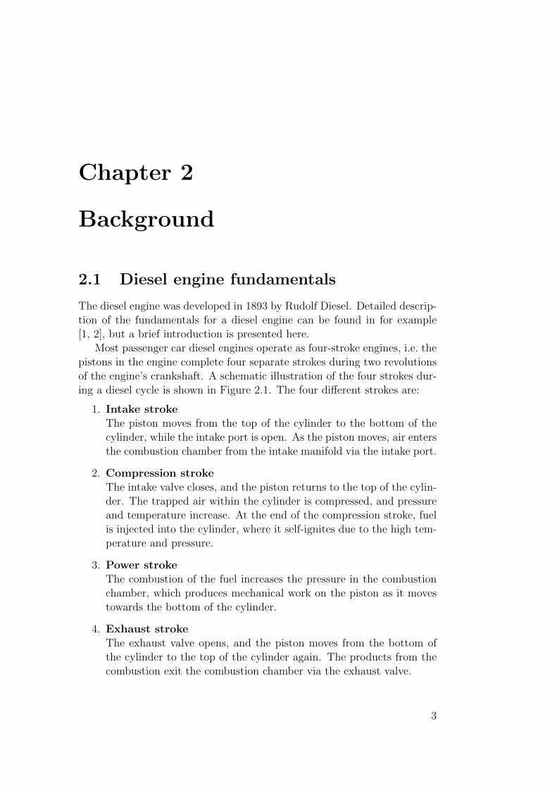
Most passenger car diesel engines operate as four-stroke engines, i.e. thepistons in the engine complete four separate strokes during two revolutionsof the engine’s crankshaft. A schematic illustration of the four strokes dur-ing a diesel cycle is shown in Figure 2.1. The four different strokes are:
1. Intake strokeThe piston moves from the top of the cylinder to the bottom of thecylinder, while the intake port is open. As the piston moves, air entersthe combustion chamber from the intake manifold via the intake port.
2. Compression strokeThe intake valve closes, and the piston returns to the top of the cylin-der. The trapped air within the cylinder is compressed, and pressureand temperature increase. At the end of the compression stroke, fuelis injected into the cylinder, where it self-ignites due to the high tem-perature and pressure.
3. Power strokeThe combustion of the fuel increases the pressure in the combustionchamber, which produces mechanical work on the piston as it movestowards the bottom of the cylinder.
4. Exhaust strokeThe exhaust valve opens, and the piston moves from the bottom ofthe cylinder to the top of the cylinder again. The products from thecombustion exit the combustion chamber via the exhaust valve.
3

Chapter 2. Background
Figure 2.1: Illustration of the four strokes during a diesel cycle. From left toright the figure shows the intake stroke, the compression stroke, the powerstroke, and the exhaust stoke. (Image courtesy of Mikael Thor.)
4

2.1. Diesel engine fundamentals
A standard diesel engine is typically direct-injected and compression-ignited, i.e. fuel is injected directly into the compressed air in the cylinderswhere it self-ignites due to the high temperature and pressure. This can becompared with port-injected and spark-ignited engines. In a port-injectedengine, fuel is injected outside the cylinders, close to the intake ports, andenters the combustion chamber together with the air. In a spark-ignitedengine a spark plug is used to ignite the fuel-air mixture after compression.A standard gasoline engine is typically port-injected and spark-ignited, al-though direct-injected gasoline engines are becoming increasingly common.
A diesel engine is normally operated with a global excess of air in thecylinders. After ignition in a diesel engine, fuel is combusted at a rate whichis mainly determined by the rate of with which the fuel is mixed with the air.The combustion in a diesel engine is therefore said to be mixing-controlled.
The combustion results in that chemical energy in the fuel is convertedto mechanical work on the piston. The efficiency of this energy conversionis dependent on the details of the combustion process. In broad terms, afast combustion that occurs close to piston top dead center (TDC) resultsin high fuel conversion efficiency, and slow combustion located further awayfrom TDC results in low fuel conversion efficiency. The conversion efficiencyis directly linked to the fuel consumption of the engine.
Diesel fuel mainly consists of hydrogen (H) and carbon (C), and ideallythe combustion of fuel and oxygen (O2) would only result in carbon dioxide(CO2) and water (H2O) according to the reaction
HxCy +(x
4+ y)O2 → yCO2 +
x
2H2O (2.1)
where x is the number of hydrogen atoms and y is the number of carbonatoms in a fuel molecule. It can be noted that the excess air within thecylinders is not included in this description of the reaction.
Unfortunately, this ideal reaction is not a full description of the combus-tion process in a diesel engine. Unwanted products are also formed duringthe combustion. The main issue for a diesel engine is the formation of theharmful emissions nitrogen oxides (NOX) and soot. NOX is formed duringthe combustion in regions with high temperature and an excess of oxygenavailable, and soot is mainly formed during the combustion in regions withlower temperature and little oxygen available. Most of the formed soot isoxidized later during the combustion at high temperatures when there isoxygen available.
Because soot and NOX are formed by very different and sometimes com-peting processes; combustion control to decrease one of them typically gen-erates an increase in the other. This is commonly known as the dieseldilemma, and is a well-known issue with diesel engines. Furthermore, as the
5

Chapter 2. Background
fuel consumption is also directly linked to the combustion process, there isoften a trade-off between fuel consumption, NOX emissions and soot emis-sions in a diesel engine.
Besides the emissions of NOX and soot, issues for a diesel engine are alsounwanted emissions of carbon monoxide (CO), which are formed duringthe combustion, and unburned hydrocarbons (HC), which is a result ofincomplete combustion of the fuel.
2.2 Driving forces for diesel engine develop-
ment
Although diesel engines have been around since 1893, there is an ongoingdevelopment on diesel engines for passenger cars. The main driving forcefor this development during the last years has been the increasingly stricterlegislation on emissions.
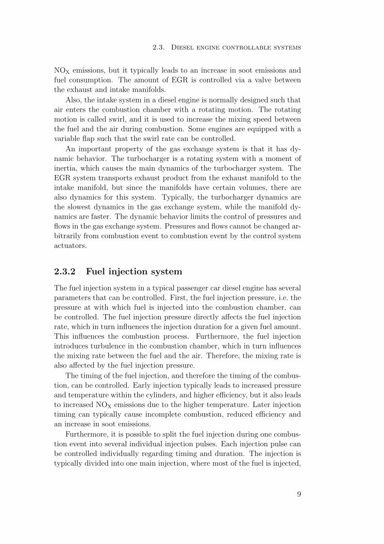
In Europe, the emission regulations are set by the European Union.The regulations were once specified in Directive 70/220/EEC, but in 2007this Directive was replaced by Regulation 715/2007. An illustration of theprogress of the emission regulations in Europe for NOX and soot emissionsis shown in Figure 2.2. The emission levels for a vehicle are measured bydriving the vehicle in a chassis dynamometer. A standardized test cycle de-fined in Directive 98/69/EC, called the New European Drive Cycle (NEDC)is used. The NEDC cycle is a dynamic driving cycle, and is designed to rep-resent both city driving and highway driving. The duration of the cycle is1180 seconds, and during the cycle, emissions are sampled and analyzed.The emission limits are expressed in grams per kilometer driving.
Another strong driving force for the development of diesel engines is fuelconsumption, or equivalently emissions of CO2. Low fuel consumption isa strong selling argument for passenger cars, but there is also upcominglegislation regarding CO2 emissions. In 2007, the European Commissionproposed legislation for new passenger cars regarding CO2 emissions. Thislegislation, adopted in 2009 by the European Parliament and the Councilensures that fleet average emissions from new passenger cars in EU do notexceed 120 grams per kilometer [3]. The legislation is valid from 2015 witha phase in period that started in 2012. A target of 95 grams per kilometeris also specified for the year 2020.
6

2.2. Driving forces for diesel engine development
0 0.1 0.2 0.3 0.4 0.5 0.6 0.7 0.8 0.90
0.02
0.04
0.06
0.08
0.1
0.12
0.14Euro 1 (1992)
Euro 2 (1996)
Euro 3 (2000)
Euro 4 (2005)
Euro 5 (2009)Euro 6 (2014)
NOX (g/km)
Soo
t (g/
km)
Figure 2.2: The progress of NOX and soot emission standards in Europe fordiesel engine passenger cars.
7

Chapter 2. Background
2.3 Diesel engine controllable systems
To be able to handle the increasingly strict emission legislation and strongerdemands on fuel consumption, there is an ongoing rapid development ofdiesel engines. A major part of this development is that different systemswithin the engine are enhanced or added. These systems can be dividedinto two main categories; the first one is that systems are used such thatthe operation of the diesel engine itself can be better controlled, and thesecond one is after-treatment systems that remove harmful emissions fromthe combustion process after the emissions leave the cylinders. The opera-tion of the engine itself can be influenced either by designing the hardwareof the combustion system, by controlling the air that enters the combustionchamber via the gas exchange system, or by controlling how fuel is injectedinto the air. This section describes common controllable systems in a typicalpassenger car diesel engine today.
2.3.1 Gas exchange system
The air that is compressed in the cylinders enters the combustion chambervia the gas exchange system. There are several controllable system withinthe gas exchange system.
To be able to increase the amount of air that enters the combustionchamber, a diesel engine is usually equipped with a turbocharger system.The hot exhaust gases produced by the engine are driving a turbine, whichin turn drives a compressor on the intake side of the gas exchange system.The compressor increases the pressure in the intake manifold which in turnincreases the amount of air that enters the combustion chamber. By in-creasing the amount of air in the combustion chamber, the possible amountof fuel that can be injected before too much soot is formed is increased (asdescribed in Section 2.1, soot is formed when there is little oxygen avail-able). Therefore, the turbocharger system is used to increase the upper loadlimit of a diesel engine. The pressure in the intake manifold is controlledby adjusting the amount of exhaust gases that is fed through the turbine.A turbocharger system is more or less standard on a passenger car dieselengine today. To be able to increase turbocharger efficiency, one possibilityis to use a two-stage turbocharger system. This is becoming more and morecommon for passenger car diesel engines.
Furthermore, it is possible to feed some of the exhaust gases out fromthe engine back into the intake side of the engine, where it is mixed withfresh air. This is called exhaust gas recirculation (EGR). EGR leads todilution of fresh intake air with combustion products, which in turn resultsin a decrease in combustion temperature. Use of EGR is a tool to decrease
8
2.3. Diesel engine controllable systems
NOX emissions, but it typically leads to an increase in soot emissions andfuel consumption. The amount of EGR is controlled via a valve betweenthe exhaust and intake manifolds.
Also, the intake system in a diesel engine is normally designed such thatair enters the combustion chamber with a rotating motion. The rotatingmotion is called swirl, and it is used to increase the mixing speed betweenthe fuel and the air during combustion. Some engines are equipped with avariable flap such that the swirl rate can be controlled.
An important property of the gas exchange system is that it has dy-namic behavior. The turbocharger is a rotating system with a moment ofinertia, which causes the main dynamics of the turbocharger system. TheEGR system transports exhaust product from the exhaust manifold to theintake manifold, but since the manifolds have certain volumes, there arealso dynamics for this system. Typically, the turbocharger dynamics arethe slowest dynamics in the gas exchange system, while the manifold dy-namics are faster. The dynamic behavior limits the control of pressures andflows in the gas exchange system. Pressures and flows cannot be changed ar-bitrarily from combustion event to combustion event by the control systemactuators.
2.3.2 Fuel injection system
The fuel injection system in a typical passenger car diesel engine has severalparameters that can be controlled. First, the fuel injection pressure, i.e. thepressure at with which fuel is injected into the combustion chamber, canbe controlled. The fuel injection pressure directly affects the fuel injectionrate, which in turn influences the injection duration for a given fuel amount.This influences the combustion process. Furthermore, the fuel injectionintroduces turbulence in the combustion chamber, which in turn influencesthe mixing rate between the fuel and the air. Therefore, the mixing rate isalso affected by the fuel injection pressure.
The timing of the fuel injection, and therefore the timing of the combus-tion, can be controlled. Early injection typically leads to increased pressureand temperature within the cylinders, and higher efficiency, but it also leadsto increased NOX emissions due to the higher temperature. Later injectiontiming can typically cause incomplete combustion, reduced efficiency andan increase in soot emissions.
Furthermore, it is possible to split the fuel injection during one combus-tion event into several individual injection pulses. Each injection pulse canbe controlled individually regarding timing and duration. The injection istypically divided into one main injection, where most of the fuel is injected,
9

Chapter 2. Background
one or several pilot injections which appear before the main injection, andone or several post injections. Pilot injections are mainly used to decreasethe combustion rate to limit combustion noise from the engine, and postinjections are mainly used to enhance soot oxidation during the late stageof the combustion.
2.3.3 After-treatment systems
Unwanted engine-out emissions that are formed during the combustion canbe reduced in a diesel engine by using after-treatment systems. A dieselengine is usually operated with a global excess of air, which means that thevery effective three-way-catalyst (TWC) used in gasoline engines cannot beused in a diesel engine. A diesel engine is usually equipped with an oxida-tion catalyst to convert carbon monoxide (CO) and hydrocarbons (HC) tocarbon dioxide (CO2) and water (H2O).
Furthermore, a typical passenger car diesel engine today is also equippedwith a Diesel Particulate Filter (DPF). A DPF captures most of the engineout soot, but it needs to be regenerated regularly. Regeneration is performedby operating the engine inefficiently such that the exhaust gases become hotenough to burn the accumulated soot in the DPF. The process of operatingthe engine inefficiently leads to an increase in fuel consumption during DPFregeneration.
NOX emissions cannot be reduced using the oxidation catalyst, and usu-ally this is handled by operating the engine such that NOX emissions arelow enough already out from the engine. However, due to the increasinglystricter legislation on emissions, special after-treatment systems for NOX
emissions have started to be introduced for passenger car diesel engines.Examples of after-treatment systems for NOX emissions are Selective Cat-alytic Reduction (SCR) systems and Lean NOX Traps (LNT). SCR is ameans of converting NOX into diatomic nitrogen (N2) and water (H2O).To do this, a reactant, usually ammonia or urea, is added to the stream ofexhaust gases. LNT is a system that absorbs NOX molecules, similar to aDPF system for soot emissions. The LNT system needs to be regeneratedregularly, since only a limited amount of NOX molecules can be trapped.
2.4 Engine management system challenges
The operation of an engine is controlled by the engine management system(EMS). In the EMS, control strategies and set points for the controllablesystems should be defined such that optimal engine operation is achieved.The complexity of a typical passenger car diesel engine today, with the many
10

2.4. Engine management system challenges
different controllable systems presented in Section 2.3 makes it possible tooperate a diesel engine at efficient conditions, but finding optimal controlstrategies and set points in the EMS is a difficult challenge.
First of all, due to the different properties of NOX formation, soot forma-tion, and fuel efficiency described in Section 2.1, it is a challenge to controlthe various system in an engine such that the optimal trade-off between fuelconsumption and emissions is always achieved. Since the performance of anengine regarding emissions and fuel consumption is evaluated for a completevehicle driving cycle, it is even a challenge to define the optimal operationof one single combustion event during the cycle. For example, it is bene-ficial to allow an increase of emissions in favor for lower fuel consumptionin one combustion event during the cycle, if emissions can be decreased inany another combustion event during the cycle with less penalty on fuelconsumption. The optimal trade-off for one single combustion event cannotbe determined unless all combustion events throughout the driving cycleare considered simultaneously.
Furthermore, due to the dynamics in the gas exchange system describedin Section 2.3.1, the different combustion events throughout a driving cy-cle cannot be controlled individually, but is dependent on previous controlactions.
The many degrees of freedoms for the engine control systems togetherwith the dynamic behavior of the engine make the task of optimizing theEMS very challenging.
It can also be noted that since emissions and fuel consumption are eval-uated using a complete vehicle, the engine operation during a given drivingcycle is not only dependent on the engine itself, but also on the vehicle inwhich it is used. For example, a heavier vehicle result in that the enginetypically operates at higher engine loads during a cycle, and vice versa.This implies that optimal EMS settings for an engine in one vehicle aremost likely not the optimal settings for the same engine used in a differentvehicle.
11

12

Chapter 3
Engine management systemcalibration procedure
As described in Section 2.4, it is a challenging task to find optimal controlstrategies and set points in an EMS for the controllable engine systems.The following chapter describes the author’s view of the typical procedureto perform EMS calibration today within industry. The target with theprocedure is to define set points in the EMS for all controllable enginesystems such that fuel consumption is minimized for a dynamic vehicledriving cycle while constraints on accumulated engine-out emissions arefulfilled.
3.1 Initial calibration
Due to the very many degrees of freedom in an engine system, it is not (yet)possible in practice to account for all systems in a sophisticated global opti-mization procedure. Therefore, the operation of a number of the controllablesystems is calibrated separately at an early stage in the EMS calibrationprocess. These systems are calibrated based on the engine speed and loadoperating range of the engine. Examples of systems that are typically cal-ibrated at this stage are number of injection pulses for each combustionevent, individual dwell times between the different injection pulses, relativeinjection amounts in the different injection pulses, and the fuel rail pres-sure. Settings for these quantities are calibrated manually using an enginein an engine test cell, with an aim to find a reasonable balance betweenfuel consumption and emissions throughout the complete working range ofthe engine. This calibration is possibly also performed in conjunction withtuning of the engine hardware design, i.e. for example design of the pistons,design of the cylinder head, and physical location of the injectors can be
13

Chapter 3. Engine management system calibration procedure
tuned at this stage together with the manual EMS calibration.
3.2 Drive cycle optimization based on steady-
state engine operation
The next step is to calibrate settings in the EMS for the remaining sys-tems, but now account for the complete driving cycle instead of calibratingsettings in various engine operating points individually. Typically, the cal-ibratable parameters accounted for at this stage are set points for boostpressure, oxygen fraction in the intake manifold (closely coupled to theamount of EGR), and the injection timing, i.e. the timing of the completeinjection package. There are several reasons for choosing these three. First,they have a large impact on fuel consumption and emissions. Second, asdescribed in Section 2.3.1, boost pressure and oxygen fraction in the intakemanifold are associated with dynamic behavior in the gas exchange sys-tem, and therefore they should be accounted for when the complete vehiclesystem is considered.
3.2.1 Drive cycle approximation
First, a vehicle is driven according to the specified driving cycle, while thespeed and load of the engine throughout the cycle is registered. Alterna-tively, a simulation model for a complete vehicle can be used. From theresulting speed and load profiles throughout the driving cycle, a limitednumber of steady-state engine operating points are chosen such that thecomplete vehicle driving cycle can be reasonably well approximated as aweighted sum of engine operation in these engine operating points.
3.2.2 Engine mapping
Measurements are performed in an engine test cell, where the engine isoperated at steady-state conditions in the complete speed and load operat-ing range. In the various speed and load operating points, considered setpoints, i.e. typically set points for boost pressure, oxygen fraction in theintake manifold, and injection timing, are varied according to a suitabledesign of experiments methodology.
3.2.3 Drive cycle optimization
Using the measured data from the engine test cell together with the chosenrepresentative engine operating points that approximate the vehicle driv-
14

3.3. Transient compensations
ing cycle, off-line calculations are performed to minimize fuel consumptionfor the approximated driving cycle, while fulfilling constraints on accumu-lated emissions. These optimization calculations typically account for thetrade-off challenge described in Section 2.4, i.e. they account for all engineoperating points simultaneously as it calculates optimal set points for theindividual engine operation points. Methods for this are well developed anddescribed in the open literature. The approach is that a trade-off betweenfuel consumption and emissions is selected, and that all individual operatingpoints are optimized based on this selected trade-off. The process is iteratedwith different trade-offs until the performance of the approximated drivingcycle is satisfactory. Simulation models for emissions and fuel consumptionare typically used in this stage to speed up the process. This steady-statebased optimization procedure is discussed in detail in Chapter 4.
Finally, by using information from the optimal solution together with theengine measurements that cover the complete working range of the engine,optimal set points are calculated not only for the selected representativeengine operating points, but for the complete operating range of the enginewith respect to engine speed and load. These set points are stored in theEMS. The structure in an EMS is mostly based on two-dimensional gridmaps [4], and the calculated set points can be implemented directly into thisstructure. Doing this, set points are defined in the EMS for the completeworking range of the engine, not only the working range covered by theapproximated driving cycle.
The reason for that not all systems are considered in this optimizationstage is that it would be too time consuming to perform measurements in anengine test cell to completely cover all degrees of freedom for all controllablesystems. Therefore, some of the systems are calibrated manually before thisprocedure, as described in Section 3.1.
3.3 Transient compensations
Until now, the drive cycle optimization has only been performed based onsteady-state engine operation. For the set points associated with systemswith dynamics, feedback controllers are used to obtain the predefined setpoints. Even though feedback controllers are used, the set points cannot bedirectly reached during transient engine operation due to the dynamics inthe gas exchange system described in Section 2.3.1. This leads to differentemissions and fuel consumption figures during transient engine operationcompared to steady-state engine operation. As an example, during a pos-itive load transient the boost pressure does not directly reach its higherset point within the new engine operation point owing to dynamics in the
15

Chapter 3. Engine management system calibration procedure
turbocharger system. This in turn leads to reduced availability of oxygenfor combustion, and that in turn most likely leads to an increase in sootemissions during the transient (as described in Section 2.1, soot is formedwhen there is little oxygen available during combustion).
To handle this transient behavior, additional compensations are used tokeep emissions within a reasonable range during the transients. Typicallycompensations to adjust the set point for the oxygen fraction in the intakemanifold and the injection timing based on the magnitude of the engineload change are used. The calibration of these compensations is a manualprocess and is largely performed to reduce emissions spikes rather than tooptimize the overall system.
3.4 Final calibration
After the EMS calibration has been performed by first optimizing the driv-ing cycle approximated as a number of steady-state engine operating points,and then manually calibrating compensations for transient operation, theperformance of a real vehicle, driving according to the specified cycle, is eval-uated. Doing this, the defined limits on accumulated amount of emissionsare most likely not reached. The reason for this is that even though compen-sations for transient engine operation are used, emissions during transientsare most likely higher than corresponding emissions during steady-state en-gine operation used in the steady-state based drive cycle optimization.
The approach to solve this problem is typically to perform the drive cycleoptimization procedure based on steady-state engine operation again, butthis time with lower limits on accumulated emissions for the approximateddriving cycle. The whole process of steady-state drive cycle optimizationand transient compensation calibration is iterated several times with differ-ent limits on accumulated emissions in the steady-state optimization pro-cedure, until resulting vehicle performance is satisfactory. This is a timeconsuming process associated with a large amount of manual calibrationwork, both in a complete vehicle and in an engine test cell. It also results inan EMS calibration that is not aimed at optimizing the system, but insteadis focused on meeting emission regulations.
A schematic illustration of the complete EMS calibration procedure de-scribed in this Chapter is shown in Figure 3.1.
16

3.4. Final calibration
Initial calibration
Engine mapping
Approximate driving cycle
Define emission limits for the approximated drive cycle
Select trade-off between fuel consumption and emissions
Optimize individual steady-state engine operating points
Calibrate transient compensations
OK?
yes
no
Evaluate approximated drive cycle
Evaluate resulting vehicle performance
OK?
Done
Start
no
yes
Create models for fuel consumption and emissions
Calibrate the complete working range of the engine with resulting trade-off
Figure 3.1: Schematic illustration of a typical EMS calibration procedure.
17

18

Chapter 4
State of the art
This chapter describes current status within the research field of EMS op-timization. A common approach within the field is to use a model-basedstrategy for EMS optimization, and this is also the approach applied in theDiesel Engine Optimization project. Therefore, a section describing relatedwork within the field of diesel engine modeling is also included.
4.1 Engine management system optimization
This section attempts to describe the research status within the field of en-gine management system optimization. As described in Chapter 3, the pro-cedure to perform EMS calibration is typically separated into optimizationof steady-state engine operation and transient engine operation. Researchwithin the area of EMS optimization is to a large extent also divided intoresearch for drive cycle optimization based on steady-state engine operation,and research within optimization of transient engine operation.
4.1.1 Optimization based on steady-state engine op-eration
EMS optimization methods based on steady-state engine operation are welldeveloped and described in the open literature. These methods are devel-oped to handle the trade-off challenge described in Section 2.4, i.e. to findset points for the EMS such that the full vehicle system meets the legisla-tive limits of soot and NOX emissions. The optimization problem for the
19

Chapter 4. State of the art
approximated driving cycle can be formulated mathematically as:
minz
n∑
i=1
f (nei, Tei, zi) ti
s.t.n∑
i=1
gj (nei, Tei, zi) ti ≤ Gj, j = 1 . . .m
(4.1)
where f (nei, Tei, zi) if the fuel mass flow (g/s) at engine speed nei, enginetorque Tei, and set points zi corresponding to engine operating point i. Thenumber of engine operating points is denoted n. The time spent in en-gine operating point i in the approximated driving cycle is denoted ti. Thenumber of emission constraints is denoted m, and the mass flow (g/s) ofemission j in engine operating point i is denoted gj (nei, Tei, zi). The con-straint on maximum accumulated mass of emission j for the approximateddriving cycle is denoted Gj.
A common approach to solve the optimization problem (4.1) is to use aLagrangian relaxation approach [5]. The Lagrangian function to the opti-mization problem is
L (z,λ) =n∑
i=1
f (nei, Tei, zi) ti +m∑
j=1
λm
(n∑
i=1
gj (nei, Tei, zi) ti −Gj
)(4.2)
where λj ≥ 0, j = 1 . . .m are Lagrangian multiplicators (or dual variables)corresponding to each emission constraint. Since the n engine operatingpoints are completely independent from each other in the approximateddriving cycle, the Lagrangian function can be reformulated as
L (z,λ) =n∑
i=1
(f (nei, Tei, zi) +
m∑
j=1
λmgj (nei, Tei, zi)
)ti −
m∑
j=1
λmGj
(4.3)The dual function to the optimization problem (4.1) is defined as
h (λ) = minzL (z,λ) (4.4)
The function h (λ) is concave [5], and for given values of λj ≥ 0, j = 1 . . .m,the function value can be calculated by solving n optimization problems.For each engine operating point in the approximated driving cycle, thefollowing optimization problem is solved
minz
(f (ne, Te, z) +
m∑
j=1
λmgj (ne, Te, z)
)(4.5)
20

4.1. Engine management system optimization
where z are set points for the considered controllable systems in the engineoperating point, ne is the engine speed, and Te is the requested enginetorque.
According to the theory of weak duality [5] it follows that for all zi, i =1 . . . n that are feasible in (4.1), the following relation holds
h (λ) ≤n∑
i=1
f (nei, Tei, zi) ti (4.6)
This means that if it is possible to find values λj? ≥ 0, j = 1 . . .m and
zi?, i = 1 . . . n such that
h (λ?) =n∑
i=1
f (nei, Tei, zi?) ti (4.7)
and zi?, i = 1 . . . n yields a feasible solution to (4.1), then zi
?, i = 1 . . . nis the optimal solution to (4.1). If it is possible to meet the emission re-quirements this solution exists and can be found by using a gradient searchalgorithm acting on the concave dual function h (λ). Early work based onthis approach for gasoline engine applications can be found in [6, 7] andearly work for diesel engine applications in [8].
It can be noted that the optimal solution to (4.1) is given by minimizinga weighted sum of fuel consumption and emissions in each individual engineoperating point in the approximated driving cycle, where the same weightsare used for all points (in each engine operating point (4.5) is solved). Thiscan also be motivated from a non-mathematical perspective. As describedin Section 2.4, it is beneficial to allow an increase of emissions in favor forlower fuel consumption in one operating point in the cycle, if emissionscan be decreased in any another operating point during the cycle with lesspenalty on fuel consumption. This implies that for the optimal solutionit is not possible to allow an increase of emissions in favor for lower fuelconsumption in one operating point, and decrease emissions in another op-erating point with less penalty on fuel consumption. This means that forthe optimal solution, there should be exactly the same trade-off betweenfuel consumption and emissions at all operating points. This is achieved byminimizing a weighted sum of fuel consumption and emissions in all engineoperating points in the cycle, using the same weights for all points, i.e bysolving (4.5) in each operating point.
The typical procedure to perform EMS calibration using this approachis to first select values for the weights (Lagrangian multipliers) between fuelconsumption and emissions. When all engine operating points are optimizedwith the selected weights, the performance of the approximated driving
21

Chapter 4. State of the art
cycle is evaluated (the approximated driving cycle consists of a weightedsum of the optimized engine operating points). Depending on the resultingperformance, different weights between fuel consumption and emissions areselected, and the process is repeated. The process is repeated until resultingperformance of the approximated driving cycle is satisfactory.
At the stage where an individual engine operating point is optimizedwith given weights between fuel consumption and emissions, it is commonto utilize a simulation model to find optimal set points. Using measuredengine data from an engine mapping as described in Section 3.2.2, modelsfor emissions and fuel consumption that account for changes in the setpoints are created. Instead of optimizing set points manually in an enginetest cell, the optimization is performed using the simulation models. Usingthis approach, the complete steady-state optimization procedure can beperformed off-line. There are several examples of model-based methodsdescribed in the literature [9, 10, 11, 12, 13, 14, 15, 16, 17]. There are alsocommercial software developed for this. Examples are AVL CAMEOTM,Ricardo µCal, ETAS ASCMO, FEV TOPexpert, IAV EasyDoE, and D2TIC2.
4.1.2 Optimization of transient engine operation
Research within the field of transient engine operation is not as well devel-oped, and the research work has mainly been focused on finding optimalactuator trajectories for specified single engine transients. Examples ofmethods for this are presented in [18, 19, 20]. Optimal actuator trajecto-ries for single transients cannot be directly transferred to a general EMSstrategy that can handle any transient engine scenario, and much researchhas been focused on developing transient control strategies based on theidentified optimal actuator trajectories. Based on this, there are severalexamples of control strategies for transient engine operation based on theoxygen fraction in the intake manifold [21, 22, 23, 24]. The research basedon optimal actuator trajectories for single transients has mostly been fo-cused on reducing emission spikes during transient engine operation, notto find the optimal trade-off between emissions and fuel consumption withrespect to a complete driving cycle. This means that the approach is sim-ilar to the work procedure when transient compensations are calibrated asdescribed in Section 3.3.
Some work has been performed to optimize the EMS in a diesel enginefor a complete driving cycle, taking both steady-state and transient engineoperation into consideration. Atkinson et. al. has used a model-based ap-proach based on neural networks to achieve a proof-of-concept of the benefit
22

4.2. Diesel engine modeling
of a model-based transient calibration process [25, 26]. Brahma et. al. hasdeveloped a model-based transient calibration process to optimize settingsin a standard EMS, taking both steady-state and transient engine operationinto consideration [27, 28]. The approach in their work is to complementthe manual work process of performing EMS calibration, rather than toreplace it. Based on an existing EMS calibration, simulation models andsearch algorithms are used to adjust the calibration such that emissions fora driving cycle are decreased without increasing the fuel consumption.
It can be noted that the possibility to account for transient engine andvehicle behavior during EMS optimization becomes more important as anew global harmonized test cycle, the World-Harmonize Light-Duty TestCycle (WLTC), is being developed. The development of this new test cycleis ongoing, but the test cycle will most likely include a larger portion oftransient driving compared to the currently used test cycle in Europe, theNew European Driving Cycle (NEDC) [29].
4.2 Diesel engine modeling
The approach taken in the Diesel Engine Optimization project is to usea model-based strategy for EMS optimization, i.e. to utilize a simulationmodel as a tool in the EMS optimization process, and also to use a sim-ulation model to evaluate the resulting vehicle performance. This impliesthat a complete diesel engine vehicle system simulation model is needed,including sub-models for the engine, the vehicle, and the driver. The mainfocus within the complete simulation model is the model of the diesel en-gine itself, including the gas exchange system and the combustion withinthe cylinders. For the other systems, simple models that capture the maindynamic effects are used.
This section attempts to describe current state of the art within thefield of diesel engine modeling. Engine modeling is usually separated intomodeling of the gas exchange system and modeling of the combustions. Thisis the approach taken also within the Diesel Engine Optimization project.
4.2.1 Gas exchange system modeling
For the gas exchange system, there are different simulation models avail-able in the open literature, and there are also commercial software special-ized for this. Examples of commercial software for gas exchange modelingare Gamma Technologies GT-POWER, AVL BOOST, and Ricardo WAVE.These software are advanced, and have the capability to model a gas ex-change system in detail, including estimation of crank-angle resolved pres-
23

Chapter 4. State of the art
sures, flows, and temperatures in the system. In this project, the model ofthe gas exchange system only needs to capture the main dynamic effectsin the engine. Therefore, a more suitable approach is to use a mean valuemodel for the gas exchange system. Mean value models for diesel enginesare well developed and described in the literature [30, 31, 32], and thereare also simulation toolboxes available for this, e.g. the Engine DynamicsLibrary for Modelica R© [33].
4.2.2 Combustion modeling
Much research has been performed within the field of diesel engine combus-tion modeling, although most of the the research has not been focused onthe application of using the simulation models for EMS optimization.
In general, models can be derived from two opposite directions. Theclassical approach is to use first principles modeling, leading to multi-dimensional computational fluid dynamic (CFD) models combined withdetailed models for the combustion chemistry. Such models give insightinto fundamental properties of the combustion but are less adequate to pre-dict absolute levels of emissions and are also computationally demanding.Models of this type are described in detail in [34] and [35].
Less demanding is to use zero-dimensional or low-dimensional combus-tion models, which are based on first principle models, but that are substan-tially reduced in model complexity. Examples of this are models for NOX
emissions based on the extended Zeldovich mechanism [36, 37, 38]. An-other example of reduced models is a mean value model for soot emissionsdescribed in [39]. Although less computational demanding, these modelsare too simple to give accurate predictive information.
On the other side of the scale is to use models that are based purely onmeasured data from a real engine, where a smooth function is typically usedto interpolate between measured data points. Such models are known asdata-driven, or black-box since the predicted outputs are based on simplefunctions of the measured data. Data-driven models can perform accuratepredictions within the measured operating range of the engine, but have verylimited prediction performance outside the range. Several different types ofdata-driven combustion models are described in the literature. Examples ofthis are models based on neural networks [25, 40], models based on Gaus-sian processes [41], global regression models [42], and global-local modelapproaches where a global model is constructed by switching or weighingbetween different local models depending on the engine speed and injectedfuel operating point of the engine [43, 44, 45]. The data-driven models de-scribed above are all designed for specified limited applications, different
24

4.2. Diesel engine modeling
from the application in this project, and general information regarding cal-ibration procedure and prediction performance of the models is typicallynot available. Therefore, none of the described models have been able to beidentified as suitable for this project.
25

26

Chapter 5
Scope and Limitations
This chapter describes the overall goal for the Diesel Engine Optimizationproject. Based on this goal, the scope and limitations applied to the workpresented in this thesis is presented.
5.1 Main goal and approach
The overall goal within the Diesel Engine Optimization project is to developa method such that the work load and cost to perform EMS calibration inan engine development project can be decreased.
The approach within the project to be able to decrease the work load isto develop methods such that less parts of the EMS calibration process haveto be performed manually in a complete vehicle or in an engine test cell,and to instead be able to perform larger parts of the work using automatedmeasurements in an engine test cell and off-line calculations based on thesemeasurements. To be able to do this it is suitable to utilize simulationmodels, and a model-based approach has been adopted within the project.
Furthermore, since a large part of the manual work load within the EMScalibration process consists of calibration of compensations for transientengine operation, a focus within the project is to develop a method tohandle transient engine operation in a structured way.
5.2 Engine modeling
The model-based approach implies that a simulation model for a diesel en-gine vehicle system is needed. The model should describe how fuel consump-tion and emissions for a complete vehicle, driving according to a dynamicdriving cycle, depend on settings in the EMS. Furthermore, the focus on
27
Chapter 5. Scope and Limitations
transient engine operation implies that the simulation model needs to ac-count for the main effects on fuel consumption and emissions also duringtransient engine operation. The simulation model also needs to be as fast aspossible to execute, since its intended usage is to develop EMS optimizationstrategies. It is advantageous if various EMS strategies can be comparedwithin a reasonable amount of time during the development. The mainintended usage for the model is to use it as a tool in the EMS optimiza-tion procedure. In this project, the simulation model will also be used toevaluate resulting performance of the developed EMS strategy, since a realvehicle is not available for this.
The main focus within the complete simulation model is the model of thediesel engine itself, including the gas exchange system and the combustionwithin the cylinders. For the other systems, simple models that capturethe main dynamic effects are used. For the gas exchange system, a meanvalue modeling approach is applied according to descriptions in [30, 31, 32].For the combustion, as described in Section 4.2, a wide range of models areavailable in the open literature. However, a model suitable for this projecthas not been found, and included in the scope of the thesis is to developand implement a combustion model for this application.
5.3 Engine management system optimization
The scope of the work regarding EMS optimization is to develop a methodthat fulfills the goals of the project, i.e. a method such that the work loadto perform EMS calibration can be decreased, and also that a larger part ofthe work can be performed off-line by using engine measurements from anengine test cell, instead of performed manually in an engine test cell or in acomplete vehicle. An important aspect is that the developed method shouldbe able to be implemented in practice. As described in Section 4.1, muchresearch has been performed with respect to transient engine operation,although few results have been adopted by industry as methods that areused in practice [4].
5.4 Limitations
To be able to approach the complex task of developing an EMS optimizationstrategy within the frame of this thesis, a number of limitations have beenintroduced.
First, after-treatment systems are not considered, i.e. the optimizationproblem in this project is defined as minimizing fuel consumption for a
28
5.4. Limitations
dynamic driving cycle while fulfilling constraints on engine-out emissions.Furthermore, the considered constraints are only limitations on accumulatedNOX and soot emissions. The reason for choosing these constraints is that,as described in Section 2.1, NOX and soot emissions are the main issues fora diesel engine.
Second, engine warm-up is not considered, i.e. the simulation model andthe EMS optimization strategy only need to account for a fully warmed upengine.
Finally, as described in Section 2.3, there are several degrees of freedomin a typical passenger car diesel engine, but in this project, these are limitedto only three. The considered degrees of freedom are the boost pressure,the oxygen fraction in the intake manifold, and the timing of the completeinjection package. The reason for choosing these three is that the boostpressure and oxygen fraction in the intake manifold are related to the gasexchange system, and are associated with the main dynamic effects in anengine during transients. The injection timing is the most significant cal-ibration parameter for the fuel injection with respect to the late stages ina typical EMS calibration process, where complete vehicle performance isconsidered. As described in Chapter 3, other fuel injection related degreesof freedom, such as number of injections, and fuel amounts and individ-ual timings for the different injection pulses, are typically calibrated in anearlier stage in the calibration process.
An important aspect is that the EMS strategy should be developed withthe defined limitations taken into consideration. The strategy should bedeveloped such that it is possible to extend it to account also for the effectsthat are neglected due to the introduced limitations.
It can be noted that the defined limitations are very similar to the lim-itations applied also in the drive cycle optimization procedure as describedin Chapter 3.
29

30

Chapter 6
Contributions
The aim of the research presented in this thesis is to develop methods andstrategies for diesel engine management system optimization. The methodfor doing this is to use a model-based approach, i.e. to use a simulationmodel of a diesel engine vehicle system as a tool in the EMS optimizationprocedure. The research has resulted in scientific contributions both withinthe field of engine management system optimization, and also within thefield of diesel engine modeling.
6.1 Diesel Engine Modeling
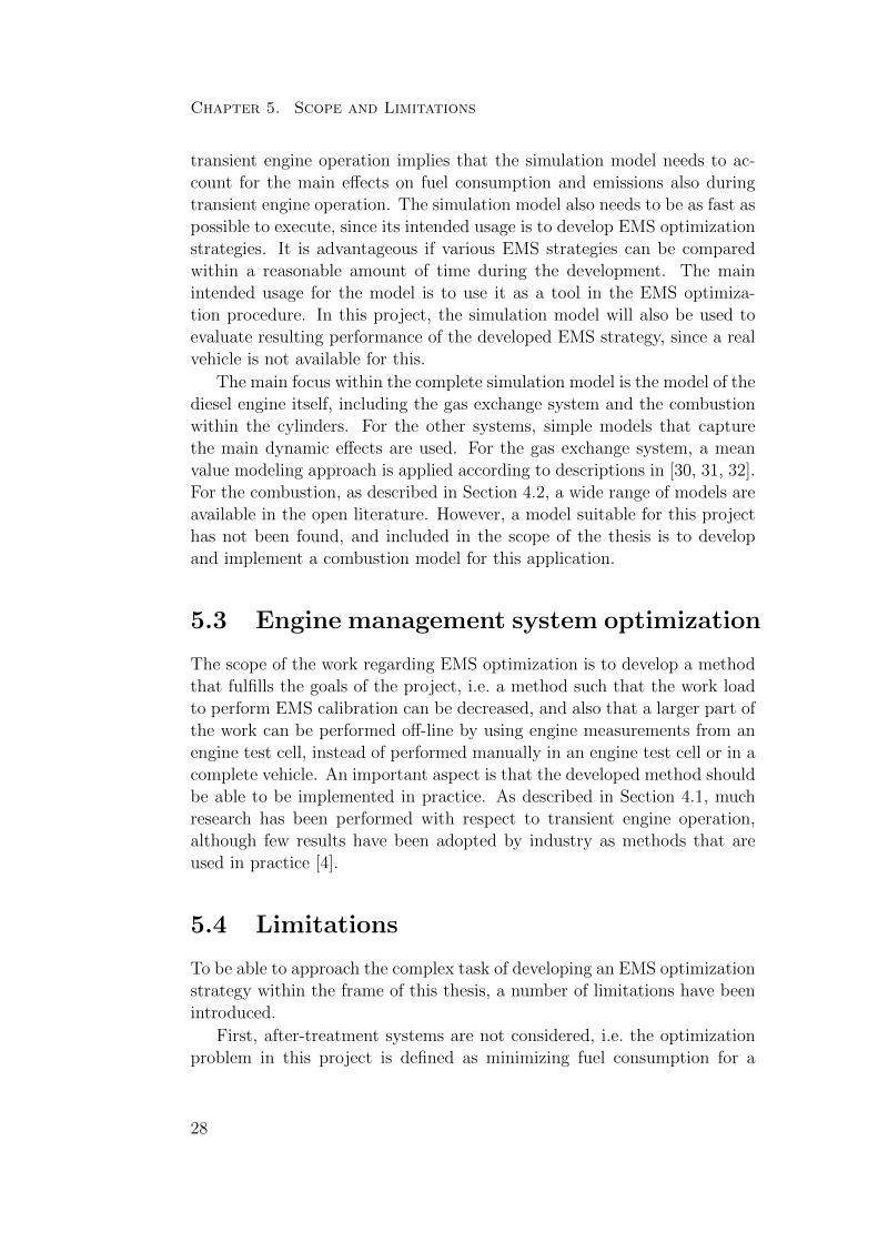
This thesis includes papers that describe the development and implemen-tation of a complete vehicle system simulation model intended to be usedfor development of engine management system strategies. The simulationmodel consists of four main sub-models; a model for the engine, a model forthe vehicle, a model for the driver, and a model for the engine managementsystem. A schematic illustration of the complete diesel engine vehicle systemsimulation model is shown in Figure 6.1. The main focus in the completesimulation model is modeling of the engine with its gas exchange system,combustion and emission formation. The other sub-systems are modeledusing simple, physical based models, which capture the main interactioneffects with the engine.
The model can perform a simulation of a vehicle driving according to apredefined vehicle driving cycle and it estimates fuel consumption togetherwith emissions of NOX and soot during the complete cycle depending onsettings in the EMS. The model reacts on calibration changes in the en-gine management system with respect to set points for boost pressure, setpoints for oxygen fraction in the intake manifold, and injection timing. Italso accounts for transient effects in the engine caused by dynamics in the
31

Chapter 6. Contributions
Vehicle model
Engine model
EMS model
Driver model
Acc. pedal VGT area
Air system states
Fuel injection
Torque
Vehicle speed
Engine speed Engine speed
NOX emissions
Soot emissions
Vehicle speed Gear Gear
EGR area
Drive cycle
Figure 6.1: Schematic illustration of the implemented complete diesel enginevehicle system simulation model with its four sub-models and the maininterfaces between them.
gas exchange system. The simulation model has been implemented in theMatlab Simulink environment, and the simulation time is in the range of10 to 20 times faster than real-time on a standard computer. These prop-erties make the model a useful tool for development of EMS optimizationstrategies.
A detailed description of the combustion models within the completesimulation model can be found in Paper 1, Paper 2, and Paper 3. Thecomplete vehicle system simulation model is described in detail in Paper 4.
6.2 Diesel Engine Management System Op-
timization
This thesis also includes papers that describe the development and evalu-ation of a novel method to calculate set points in an EMS for controllableengine quantities. The set points are calculated with an aim to minimizefuel consumption for a given vehicle driving cycle, while fulfilling require-ments on accumulated engine-out emissions. The method to do this is basedon existing methodologies developed for steady-state engine operation, de-scribed in Section 4.1.1, but extended to handle transient effects caused bydynamic effects in the gas exchange system.
As described in Section 4.1.1, optimal set points for a driving cycle, ifall engine operating points in the cycle can be controlled arbitrarily, areset points such that all engine operating points are operated with the sametrade-off between fuel consumption and emissions. Methods are developedto account for this during steady-state engine operation. However, usingthe calibration method described in Chapter 3, this optimization criterionis violated during transient engine operation due to the dynamic behavior
32

6.2. Diesel Engine Management System Optimization
of the gas exchange system. In transient engine operation, compensationsare used, but these compensations are only focused on reducing emissionsspikes.
The main idea with the EMS optimization method introduced in thisthesis is to try to fulfill the optimization criterion also during transientengine operation. The method to do this is to separate the various enginesystems with respect to their different corresponding dynamic time scales.The idea is to adapt faster systems to fulfill the optimization criterion whenslower systems do not reach their optimal steady-state values. In this thesis,the considered set points are the set point for boost pressure, the set pointfor oxygen fraction in the intake manifold, and the injection timing. It isassumed that the dynamics associated with the boost pressure set point isslowest, the dynamics associated with the set point for the oxygen fractionin the intake manifold is a little bit faster, while, for obvious reasons, thereare no dynamics associated with the injection timing.
To be able to fulfill the optimization criterion also in transient engineoperation, the vehicle driving cycle can not be approximated as a limitednumber of steady-state engine operating points, instead it is represented byall combustion events during the cycle, and the aim is that all combustionevents during the cycle should be operated with the same trade-off betweenfuel consumption and emissions.
In the calibration procedure described in Chapter 4, all set points arecalibrated based on the engine speed and load with an aim to fulfill theoptimization criterion in the complete working range of the engine. Theidea with the introduced method is to first perform the optimization in asimilar way. The boost pressure set points is then assumed to be associatedwith slow dynamics, and during transient operating the dynamics of theboost pressure will violate the optimality. Therefore, a second optimizationstage is performed, where the set points for faster systems (i.e. the set pointfor the oxygen fraction in the intake manifold and the injection timing)are optimized in the complete working range of the engine with respect toengine speed, load and actual boost pressure in the system. This way, theset point for the oxygen fraction in the intake manifold and the injectiontiming are adjusted to fulfill the optimization criterion even when the actualboost pressure in the system has not reached its set point. Finally, a similarstep is performed again where only the injection timing is considered. Theinjection timing is optimized in the complete working range of the enginewith respect to engine speed, load, actual boost pressure in the system, andactual oxygen fraction in the intake manifold. This leads to an adjustmentof the injection timing such that the optimization criterion is fulfilled alsowhen the oxygen fraction in the intake manifold has not reached its set
33

Chapter 6. Contributions
point.
Using this method, transient compensations are automatically intro-duced in the drive cycle optimization stage of the EMS calibration process,and there is thus no need to add extra functionality for this purpose. Thecompensations are calculated similarly to the settings for steady-state en-gine operation, with the same system optimization approach. This meansthat the compensations during transient engine operation are calculatedwith the aim to optimize the complete system, with respect to a completedriving cycle, instead of calibrated with the aim to reduce emission spikes
Furthermore, optimal set points for the complete working range of theengine can be calculated off-line and stored in an EMS using for examplegrid maps, similar as for the steady-state approach described in Section 3.2.This leads to optimization results that can be implemented as a generalEMS strategy that calculates set points for any (transient or steady-state)driving scenario.
The intended work flow to implement the EMS strategy in a EMS cali-bration procedure is to first perform initial calibration as described in Sec-tion 3.1. Then, an engine is mounted in an engine test cell, where automatedmeasurements are performed such that models for emissions, generated en-gine torque, and the gas exchange system can be created. The describedEMS optimization strategy is then performed such that the performance ofa simulated driving cycle is satisfactory. Finally, using the resulting EMSsettings, the performance of a real vehicle is evaluated. If the result is notsatisfactory, the EMS optimization strategy is performed again but withupdated limits on accumulated emissions for the simulated driving cycle.This process is iterated until resulting vehicle performance is satisfactory.Ultimately, if it is possible to produce models that are accurate enough, thecomplete calibration process can be performed off-line using only measure-ments from an engine test cell, and then just validated in a real vehicle.
A schematic illustration of the suggested EMS calibration procedurewhen using the introduced strategy is shown in Figure 6.2. The main dif-ference compared to the EMS calibration procedure described in Chapter 3is that there is no separate calibration of transient compensations in thisproposed procedure. Therefore, the complete process within the outer loopof the calibration procedure can be performed off-line when using the EMSoptimization strategy just introduced. The amount of iterations that areneeded in the outer loop illustrated in Figure 6.2 is dependent on the pre-diction performance of the simulation models. If the simulation models areperfect, the outer loop can be removed and replaced with just a validationof the EMS calibration in a real vehicle.
An alternative option to use the described EMS optimization strategy
34

6.2. Diesel Engine Management System Optimization
Initial calibration
Engine mapping
Define emission limits for simulated driving cycle
Select trade-off between fuel consumption and emissions
Optimize complete engine operating range with selected trade-off
OK?
yes
no
Evaluate performance for simulated driving cycle
Evaluate resulting vehicle performance
OK?
Done
Start
no
yes
Create models for vehicle, gas exchange system, fuel consumption and emissions
Figure 6.2: Schematic illustration of the suggested complete EMS calibra-tion procedure using the introduced optimization strategy described in thisthesis.
35

Chapter 6. Contributions
in an EMS calibration procedure is to directly evaluate the resulting per-formance for a selected trade-off between fuel consumption and emissionsusing a real vehicle instead of using a simulation model. This alternativeprocedure removes the need for simulation models of the vehicle or for thegas exchange system. However, when using this alternative calibration pro-cedure, most likely more iterations with a real vehicle in the loop are neededto achieve satisfactory performance. This alternative procedure might be agood option if the EMS has already been optimized, but a small hardwarechange is introduced somewhere in the system. In that case, small adjust-ments in the optimal trade-off between fuel consumption and emissions canbe expected, and few iterations are needed. A schematic illustration of thisalternative procedure is illustrated in Figure 6.3.
The optimization strategy has been shown to decrease fuel consumptionfor a diesel engine vehicle compared to existing methods based only onsteady-state engine operation. Using the simulation model described inthis thesis, the strategy has been shown to decrease fuel consumption for avehicle driving according to the New European Driving Cycle with 0.56%,compared to a strategy based only on steady-state engine operation.
A more detailed description of the EMS optimization strategy can befound in Paper 5 and Paper 6.
36

6.2. Diesel Engine Management System Optimization
Initial calibration
Engine mapping
Select trade-off between fuel consumption and emissions
Evaluate resulting vehicle performance
OK?
Done
Start
no
yes
Create models for fuel consumption and emissions
Optimize complete engine operating range with selected trade-off
Figure 6.3: Schematic illustration of an alternative complete EMS calibra-tion procedure using the introduced EMS optimization strategy.
37

38

Chapter 7
Summary of included papers
This chapter provides a brief summary of the papers that constitute thebase for the thesis. Full versions of the papers are included in Part II.
Paper 1
Markus Grahn, Krister Johansson, Christian Vartia, and TomasMcKelvey, “A Structure and Calibration Method for Data-drivenModeling of NOX and Soot Emissions from a Diesel Engine”,SAE World Congress, Detroit, MI, USA, April 2012.
This paper describes the development and implementation of a new struc-ture for data-driven models for NOX and soot emissions. The model struc-ture is a linear regression model, where physically relevant input signalsare used as regressors, and all the regression parameters are defined asgrid-maps in the engine speed/injected fuel domain. The method of usinggrid-maps in the engine speed/injected fuel domain for all the regression pa-rameters enables the models to be valid for changes in physical parametersthat affect the emissions that are dependent only on the engine speed andthe amount of injected fuel, without having to include these parameters asinput signals to the models. This means that models can handle changes fordifferent parameters in the complete working range of the engine, withouthaving to include all signals that actually effect the emissions into the mod-els. The approach possibly also enables for the model to handle the maindifferences between steady-state engine operation and transient engine op-eration, thus possibly being able to use steady-state engine measurementdata to calibrate the model, but still achieve acceptable performance fortransient engine operation. This, however, is not evaluated in this study.The model structure has been used to create models for NOX and soot emis-sions. These models have been calibrated using measured steady-data from
39

Chapter 7. Summary of included papers
a 5 cylinder Volvo passenger car diesel engine with a displacement volumeof 2.4 liters, equipped with a turbocharger, an exhaust gas recirculationsystem, and a common rail injection system. The models estimate NOX
mass flow with a root mean square error of 0.0021 g/s and soot mass flowwith a root mean square error of 0.59 mg/s for the steady-state engine dataused in this study. The models are capable of reacting to different cali-bratable engine parameters, and they are also fast to execute. This makesthem suitable for development of engine management system optimization.The models could also be implemented directly into an engine managementsystem. For comparison, three other fast models of different types for NOX
and soot emissions have been implemented and evaluated.
The author of the thesis is responsible for implementing and evaluatingthe models. The author has written the main parts of the paper.
Paper 2
Markus Grahn, Krister Johansson, and Tomas McKelvey, “B-splines for Diesel Engine Emission Modeling”, 2012 IFAC Work-shop on Engine and Powertrain Control, Simulation and Mod-eling (E-COSM’12), Paris, France, October 2012.
This paper describes the equivalence between linear interpolation and B-spline functions of degree 1. The equivalence is used to express interpolationbased diesel engine NOX and soot emission models as B-spline functions,and to apply data fitting methods for B-spline functions to perform cal-ibration of the models. Using this strategy, the globally optimal modelcalibration can be calculated directly by analytically solving a minimiza-tion problem. The B-spline representation also makes it possible to controlthe smoothness and extrapolation behavior of the interpolation maps in themodels in a controlled manner. The models have been calibrated using mea-sured steady-state data from a 5-cylinder Volvo passenger car diesel enginewith a displacement volume of 2.4 liters, equipped with a turbocharger, anexhaust gas recirculation system, and a common rail injection system. Thecalibrated model for NOX emissions estimates the NOX mass flow with aroot mean square error of 0.0013 g/s, and the calibrated model for sootemissions estimates the soot mass flow with a root mean square error of0.56 mg/s. The established equivalence between linear interpolation andB-spline functions of degree 1 could also be used for calibration of othermodels of similar structure.
The thesis author is responsible for the calculations performed in thispaper. The author has written the main parts of the paper.
40
Paper 3
Markus Grahn, Krister Johansson, and Tomas McKelvey, “Data-driven Emission Model Structures for Diesel Engine Manage-ment System Development”, Accepted for publication in Inter-national Journal of Engine Research.
This paper discusses some specific data-driven model structures suitablefor prediction of NOX and soot emissions from a diesel engine. The modelstructures can be described as local linear regression models where the re-gression parameters are defined by two-dimensional look-up tables. It ishighlighted that this structure can be interpreted as a B-spline function.Using the model structure, models are derived from measured engine data.The smoothness of the derived models is controlled by using an additionalregularization term and the globally optimal model parameters can be foundby solving a linear least-squares problem. Experimental data from a 5-cylinder Volvo passenger car diesel engine is used to derive NOX and sootmodels, using a leave-one-out cross validation strategy to determine the op-timal degree of regularization. The model for NOX emissions predicts theNOX mass flow with an average relative error of 5.1% and the model for sootemissions predicts the soot mass flow with an average relative error of 29%for the measurement data used in this study. The behavior of the modelsfor different engine management system settings regarding boost pressure,amount of exhaust gas recirculation, and injection timing has been studied.The models react to the different engine management system settings in anexpected way, making them suitable for optimization of engine managementsystem settings. Finally, the model performance dependence on the selectedmodel complexity, and on the number of measurement data points used toderive the models has been studied.
The thesis author is responsible for the calculations performed in thispaper. The author has written the main parts of the paper together withTomas McKelvey.
Paper 4
Markus Grahn, Krister Johansson, and Tomas McKelvey, “AComplete Vehicle System Model for Diesel EMS Development”,Technical report.
The development and implementation of a complete vehicle system simula-tion model for diesel engine management system development is described.A complete system model is needed to fully evaluate how changes in the
41

Chapter 7. Summary of included papers
engine management system affect the total fuel consumption and emissionsfor a vehicle during a transient cycle. The complete system model consistsof four sub-models with well-defined interface between them. The differentsub-models are a model for the vehicle, a model for the driver, a model forthe engine, and a model for the engine management system. The modelreacts to engine management system calibration perturbations with respectto boost pressure settings, EGR ratio settings, and injection timing settings.
The detail level of the different sub-models are chosen such that themodels catch the main fuel consumption and emission affecting phenomena,but still are reasonably fast to simulate. The model is implemented in theMatlab Simulink environment, and the simulation time of the completesystem model is in the range of 10 to 20 times faster than real-time.
The thesis author is responsible for implementing the complete simula-tion model, and for performing the simulations. The author has written themain parts of the paper.
Paper 5
Markus Grahn, Krister Johansson, and Tomas McKelvey, “ADiesel Engine Management System Strategy for Transient En-gine Operation”, 7th IFAC Symposium on Advances in Automo-tive Control, Tokyo, Japan, September 2013.
A strategy for diesel engine management systems has been introduced andevaluated. The strategy calculates set points for engine management sys-tem controllable quantities with an aim to minimize fuel consumption for agiven engine speed and requested torque profile, while keeping accumulatedemissions below given limits. The strategy is based on existing method-ology for steady-state engine operation, but extended to handle transienteffects in the engine caused by dynamics in the air system. The strategyhas been evaluated using a simulation model of a diesel engine system. Themodel estimates fuel consumption together with NOX and soot emissionsfor a transient simulation cycle depending on set points in the engine man-agement system for boost pressure, oxygen fraction in the intake manifold,and injection timing. For the transient simulation scenario used in this pa-per and with given limits on accumulated emissions, the strategy has beenshown to decrease fuel consumption with up to 0.7% compared to a strategythat is based only on steady-state engine operation.
The thesis author is responsible for developing and implementing theEMS optimization strategy, and for performing the simulations. The authorhas written the main parts of the paper.
42

Paper 6
Markus Grahn, Krister Johansson, and Tomas McKelvey, “Model-Based Diesel Engine Management System Optimization for Tran-sient Engine Operation”, Manuscript submitted for publication.
A strategy to calculate set points for controllable diesel engine systems isdescribed and evaluated. The strategy calculates set points with an aim tominimize fuel consumption for a given dynamic vehicle driving cycle, whilekeeping accumulated emissions below given limits. The strategy is basedon existing methodology for steady-state engine operation, but extended tohandle transient effects in the engine caused by dynamics in the engine airsystem. Using the strategy, set points for the complete operating range ofthe engine can be calculated off-line and stored in an engine managementsystem, hence set points can be derived for any (steady-state or transient)driving scenario. The strategy has been evaluated using a simulation modelof a complete diesel engine vehicle system. The model estimates fuel con-sumption, NOX, and soot emissions for a dynamic vehicle driving cycledepending on set points for boost pressure, oxygen fraction in the intakemanifold, and injection timing, throughout the simulation. Using this sim-ulation model, the strategy has been shown to decrease fuel consumptionfor the New European Driving Cycle with 0.56%, compared to a strategybased only on steady-state engine operation.
The thesis author is responsible for developing and implementing theEMS optimization strategy, and for performing the simulations. The authorhas written the main parts of the paper.
43

44

Chapter 8
Concluding remarks andoutlook
A novel strategy to calculate set points for controllable engine systems hasbeen developed. The introduced strategy has been evaluated using a simula-tion model of a complete diesel engine vehicle system model, also developedwithin this project. The strategy has been shown to be able to decreasefuel consumption for a given dynamic vehicle driving cycle with given lim-its on accumulated emissions, compared to a strategy that is based only onsteady-state engine operation.
By using this strategy, set points are calculated in the EMS for any(steady-state or transient) engine operation scenario, and no other tuningor calibration for this is needed. Compared to how EMS optimization isnormally performed, where set points are first optimized for steady-stateengine operation, and then compensations for transient engine operation areadded manually [4], this method is expected to both enhance the resultingfuel efficiency of the vehicle, and also to decrease the work load to performEMS calibration.
To implement the developed EMS optimization approach, the structurein a standard EMS needs to be modified. The control structure in an EMStoday is typically based on two-dimensional grid maps [4], but for the de-veloped EMS optimization strategy, a three-dimensional grid map for theoxygen fraction set point is needed, and a four-dimensional grid-map forthe injection timing is needed. It is possible to modify the structure in anEMS according to this, but three- and four-dimensional grid maps require alarge amount of storage space in the EMS, and should therefore be avoidedif possible. It might be possible to modify or simplify the EMS optimiza-tion strategy described in this thesis such that it can be implemented usingonly two-dimensional grid maps. Possibly, one option is to keep a similarstructure as in an existing EMS, but to use the EMS optimization approach
45

Chapter 8. Concluding remarks and outlook
described in this thesis to calibrate the functionality for transient compen-sations in a more structured way. This however has not been studied withinthe scope of this thesis.
The strategy has not been evaluated using a real vehicle. But since thecomparison between the introduced strategy and a strategy based only onsteady-state engine operation has been performed using the same simula-tion model, improvement in fuel efficiency is expected also when implement-ing the strategy in a real vehicle. The resulting performance of the EMSstrategy in a real vehicle compared to the performance of the strategy us-ing a simulation model is dependent on the prediction performance of thesimulation model. The prediction performance of the different sub-modelsinfluence different part of the optimization. The performance of the finalapplication is only influenced by the accuracy of the combustion models, i.e.the models for generated engine torque, NOX, and soot emissions. All othersub-models, i.e. the engine gas exchange system, the driver, the EMS, andthe vehicle are only used to find the optimal values of the Lagrangian mul-tipliers. Therefore, the prediction performance of these systems will onlyinfluence the number of iterations that has to be performed using a real ve-hicle. In this thesis, data-driven models based only on steady-state enginemeasurement data have been used to model the combustion. The modelsare designed to account for transient effects in the engine, but the resultingprediction performance of the models during transient engine operation hasnot been experimentally evaluated.
To reach the point where no iterations with a real vehicle is needed, thereare still some unresolved issues. One major challenge is to create modelsthat can predict emissions and generated torque from an engine mounted ina real vehicle, using only measurements from an engine in a test cell. Thereare several challenges associated to this. First, it is a challenge to use anengine in an engine test cell to fully replicate the operation of an enginemounted in a propulsing vehicle. For example, the temperature distribu-tion in the engine compartment and the influence from the air flow aroundthe engine caused by the motion of the vehicle is difficult to replicate in anengine test cell, and the influence on emissions due to this is most likelynot negligible. This is discussed in e.g. [27, 28]. Furthermore, there aretypically different emissions measurement techniques used when measuringemissions from a real vehicle compared to when measuring emissions in anengine test cell. For certification purposes, emissions are collected in a bagduring a complete driving cycle, and the total amount of emissions duringthe cycle are measured by weighing the collected emissions [29]. This isa time consuming process, and it does not give any information regardinginstantaneous emissions throughout the cycle. In an engine test cell, there
46

are several different other techniques used to measure emissions. Differentmeasurement techniques have been shown to result in different measuredresults. Especially for soot measurements, there are large discrepancies in-volved in using different measurement techniques [46, 47]. Also, emissionmeasurements are always associated with dynamics and time delays, andtypically faster emission measurement systems are less accurate. There-fore, it is a challenge even to evaluate the performance of emission modelson a real vehicle during transient engine operation. These issues need tobe resolved until an engine can be fully optimized using engine test cellexperiments only.
In this thesis, the optimization problem has been limited to calculateEMS settings in order to minimize fuel consumption for a vehicle drivingcycle while fulfilling constraints on accumulated engine-out emissions. How-ever, to fully optimize the complete vehicle system is a more complex task.First, as described in Section 2.3.3, modern passenger car diesel engines areequipped with after-treatment systems with a possibility to remove emis-sions after they leave the cylinders. There are several trade-off associated tothis. For example, the particulate filter can trap soot emissions to a certainextent, but when the filter is full it has to be regenerated. Regenerationis performed by operating the engine with poor efficiency, generating anengine-out gas temperature that is high enough to burn the accumulatedsoot in the filter. There is a trade-off associated with this. It might bebeneficial to allow more engine-out soot in favor for lower fuel consump-tion, but doing so will require more frequent filter regeneration, which inturn leads to an increase in fuel consumption. Furthermore, the size of theparticulate filter is important. A larger particulate filter can trap more sootemissions, but is also more expensive. This is also a challenging trade-offto account for. Similar trade-offs exist if the engine is equipped with aNOX trap. A model-based approach is suitable to find a good balance forthese various trade-offs, and the simulation model and EMS optimizationstrategy described in this thesis could be included as useful tools for this.After-treatment systems are not included in the simulation model, but dueto the well-defined interfaces in the model, this can be added if the modelshould be used for a applications where this is needed.
The optimization strategy described in this thesis has been limited toonly consider three degrees of freedom for the engine control, i.e. the setpoint for boost pressure, the set point for oxygen fraction in the intakemanifold, and the injection timing. Regarding the optimization method, itis straightforward to add more degrees of freedom. The main issue associ-ated to this is the amount of engine measurements that are needed in theengine mapping stage of the optimization procedure to cover more degrees
47
Chapter 8. Concluding remarks and outlook
of freedom, as described in Section 3.2.3.
Furthermore, the optimization problem in this thesis has been limitedto account only for constraints on accumulated NOX and soot emissions.Regarding the optimization strategy it is straightforward to add more con-straints, although additional models are needed if this is to be implemented.For example, it is straightforward to add a constraint for accumulated COemissions in the optimization procedure, but to do this, a model for COemissions is needed.
The optimization problem has also been limited to a fixed vehicle withfixed engine hardware. To fully optimize the system, also the design of thevehicle and the engine hardware should be considered. Except the modelsfor combustion, all sub-models in the complete simulation model describedin this thesis are physical based. Therefore, the model and the EMS op-timization strategy could be used to predict how changes in any of thosesystems would affect the fuel consumption of a vehicle. For example, it canbe used to investigate how a different turbocharger or how a lighter vehiclewould affect the fuel efficiency of a vehicle. First, the simulation model canbe used to evaluate the performance of the new vehicle if no changes areintroduced in the EMS, but together with the optimization strategy it canalso be used to evaluate the resulting performance of the new vehicle if theEMS is re-optimized for the new hardware. The same approach can be usedif an engine is to be used in several different vehicle applications. The EMSoptimization strategy could be used to produce individual EMS calibrationsfor each application, without performing separate engine measurements foreach application. The optimization strategy can also be used to adapt EMScalibration for hybrid vehicle applications. An initial study of the benefitto re-optimize EMS calibration for an engine used in a hybrid application,where the EMS is originally calibrated for a non-hybrid application, hasbeen performed in [48].
For the combustion system, data-driven models are used, and there-fore the model cannot be used to predict how hardware changes in thecombustion system would affect the resulting vehicle performance, withoutperforming new engine measurements. To overcome this, also the combus-tion models need to be replaced with physical based models with accurateprediction performance. At this stage, such models do not yet exist in theopen literature [34, 35].
To summarize, the optimization of a complete vehicle system is verycomplex, and there are many unresolved challenges to develop a fully opti-mized system, and to develop methods to optimize a system with a minimumamount of work load. Huge improvements in fuel efficiency can be expectedfor a fully optimized system, but large improvements can still be expected
48

if some of the unresolved issues are addressed. The research presented inthis thesis is one step in the direction of a fully optimized system.
49

50

References
[1] J. B. Heywood, Internal Combustion Engine Fundamentals. McGraw-Hill, 1988.
[2] R. Stone, Introduction to Internal Combustion Engines, 3rd ed. Pal-grave Macmillan, 1999.
[3] EU, “Regulation (EC) No 443/2009 of the European Parliament and ofthe Council: setting emission performance standards for new passengercars as part of the Community’s integrated approach to reduce CO2emissions from light-duty vehicles,” Official Journal of the EuropeanUnion, vol. L140, pp. 1–15, 2009.
[4] R. B. GmbH, Electronic Diesel Control EDC: Bosch Technical Instruc-tion. Bentley Publishers, Cambridge, USA, 2003.
[5] J. Lundgren, P. Varbrand, and M. Ronnqvist, Optimization, 1st ed.Studentlitteratur AB, 2010.
[6] E. Rishavy, S. Hamilton, J. Ayers, and M. Keane, “Engine ControlOptimization for Best Fuel Economy with emission Constraints,” SAETechnical Paper 770075, 1977.
[7] H. S. Rao, A. I. Cohen, J. A. Tennant, and K. L. V. Voorhies, “EngineControl Optimization Via Nonlinear Programming,” SAE TechnicalPaper 790177, 1979.
[8] G. Schmitz, U. Oligschlager, and G. Eifles, “Automated System for Op-timized Calibration of Engine Management Systems,” SAE TechnicalPaper 940151, 1994.
[9] R. Burk, F. Jacquelin, and R. Wakeman, “A Contribution to PredictiveEngine Calibration Based on Vehicle Drive Cycle Performance,” SAETechnical Paper 2003-01-0225, 2003.
51

References
[10] D. T. Montgomery and R. D. Reitz, “Optimization of Heavy-Duty Diesel Engine Operating Parameters Using A Response SurfaceMethod,” SAE Technical Paper 2000-01-1962, 2000.
[11] Y. Nozaki, T. Fukuma, and K. Tanaka, “Development of a Rule-basedCalibration Method for Diesel Engines,” SAE Technical Paper 2005-01-0044, 2005.
[12] E. Rask and M. Sellnau, “Simulation-Based Engine Calibration: Tools,Techniques, and Applications,” SAE Technical Paper 2004-01-1264,2004.
[13] P. Dimopoulos, A. Schoni, A. Eggimann, C. Sparti, E. Vaccarino,and C. Operti, “Statistical Methods for Solving the Fuel Consump-tion/Emission Conflict on DI-Diesel Engines,” SAE Technical Paper1999-01-1077, 1999.
[14] T. Brooks, G. Lumsden, and H. Blaxill, “Improving Base Engine Cali-brations for Diesel Vehicles through the Use of DoE and OptimizationTechniques,” SAE Technical Paper 2005-01-3833, 2005.
[15] A. Knafl, J. R. Hagena, Z. S. Filipi, and D. N. Assanis, “Dual-UseEngine Calibration: Leveraging Modern Technologies to Improve Per-formance - Emissions Tradeoff,” SAE Technical Paper 2005-01-1549,2005.
[16] J. M. Desantes, J. J. Lopez, J. M. Garcıa, and L. Hernandez, “Appli-cation of Neural Networks for Prediction and Optimization of ExhaustEmissions in a H.D. Diesel Engine,” SAE Technical Paper 2002-01-1144, 2002.
[17] H. Qiang, Y. Fuyuan, Z. Ming, and O. Minggao, “Study on ModelingMethod for Common Rail Diesel Engine Calibration and Optimiza-tion,” SAE Technical Paper 2004-01-0426, 2004.
[18] H. Sequenz, M. Mrosek, S. Zydek, and R. Isermann, “Model BasedOptimisation of a Step in Acceleration for a CR-Diesel Engine,” inProceedings of the 6th IFAC Symposium Advances in Automotive Con-trol, 2011, pp. 13 016–13 021.
[19] D. Alberer and L. del Re, “Optimization of the transient Diesel engineoperation,” SAE Technical Paper 2009-24-0113, 2009.
[20] M. Benz, M. Hehn, C. H. Onder, and L. Guzella, “Model-Based Ac-tuator Trajectories Optimization for a Diesel Engine Using a Direct
52

References
Method,” Journal of Engineering for Gas Turbines and Power, vol.133, no. 023806-1, 2011.
[21] S. Nakayama, T. Fukuma, A. Matsunaga, T. Miyake, and T. Waki-moto, “A New Dynamic Combustion Control Method Based on ChargeOxygen Concentration for Diesel Engines,” SAE Technical Paper 2003-01-3181, 2003.
[22] S. K. Chen and O. Yanakiev, “Transient NOx Emission Reduction Us-ing Exhaust Oxygen Concentration Based Control for a Diesel Engine,”SAE Technical Paper 2005-01-0372, 2005.
[23] S. Nakayama, T. Ibuki, H. Hosaki, and H. Tominaga, “An Applica-tion of Model Based Combustion Control to Transient Cycle-by-CycleDiesel Combustion,” SAE Technical Paper 2008-01-1311, 2008.
[24] D. Alberer and L. del Re, “Fast Oxygen Based Transient Diesel EngineOperation,” SAE Technical Paper 2009-01-0622, 2009.
[25] C. Atkinson, M. Allain, and H. Zhang, “Using Model-Based RapidTransient Calibration to Reduce Fuel Consumption and Emissions inDiesel Engines,” SAE Technical Paper 2008-01-1365, 2008.
[26] C. Atkinson and G. Mott, “Dynamic Model-Based Calibration Opti-mization: An Introduction and Application to Diesel Engines,” SAETechnical Paper 2005-01-0026, 2005.
[27] I. Brahma and J. N. Chi, “Development of a model-based transientcalibration process for diesel engine electronic control module tables- Part 1: data requirements, processing, and analysis,” InternationalJournal of Engine Research, vol. 13, 2011.
[28] ——, “Development of a model-based transient calibration process fordiesel engine electronic control module tables - Part 2: modelling andoptimization,” International Journal of Engine Research, vol. 13, 2011.
[29] T. V. Johnson, “Vehicular Emissions in Review,” SAE Int. J. Engines,vol. 5, no. 2, 2012.
[30] L. Eriksson, “Modeling and Control of Turbocharged SI and DI En-gines,” Oil & Gas Science and Technology, vol. 62, no. 4, pp. 523–538.
[31] J. Wahlstrom, “Control of EGR and VGT for Emission Control andPumping Work Minimization in Diesel Engines,” Ph.D. dissertation,Linkoping University, 2009.
53

References
[32] L. Eriksson, J. Wahlstrom, and M. Klein, Physical Modeling of Tur-bocharged Engines and Parameter Identification. Springer Verlag,2009, pp. 59–79, in: Automotive Model Predictive Control: Models,Methods and Applications, Editors: L. del Re, F. Allgower, L. Glielmo,C. Guardiola, and I. Kolmanovsky.
[33] J. Dahl and D. Andersson, “Gas Exchange and Exhaust ConditionModeling of a Diesel Engine using the Engine Dynamics Library,” inProceedings of the 9th International Modelica Conference, 2012.
[34] N. Peters, Turbulent Combustion. Cambridge University Press, 2000.
[35] J. Warnatz, R. W. Dibble, and U. Maas, Combustion: Physical andChemical Fundamentals, Modeling and Simulation, Experiments, Pol-lutant Formation, 4th ed. Cambridge University Press, 2010.
[36] R. Egnell, “A Simple Approach to Studying the Relation between FuelRate, Heat Release Rate and NO Formation in Diesel Engines,” SAETechnical Paper 1999-01-3548, 1999.
[37] M. Andersson, B. Johansson, A. Hultqvist, and C. Nohre, “A RealTime NOx Model for Conventional and Partially Premixed Diesel Com-bustion,” SAE Technical Paper 2006-01-0195, 2006.
[38] C. Wilhelmsson, P. Tunestal, B. Johansson, A. Widd, and R. Johans-son, “A Physical Two-Zone NOx Model Intended for Embedded Im-plementation,” SAE Technical Paper 2009-01-1509, 2009.
[39] P. Kirchen and K. Boulouchos, “Development and Validation of a Phe-nomenological Mean Value Soot Model for Common-Rail Diesel En-gines,” SAE Technical Paper 2009-01-1277, 2009.
[40] I. Brahma and C. Rutland, “Optimization of Diesel Engine OperatingParameters Using Neural Networks,” SAE Technical Paper 2003-01-3228, 2003.
[41] B. Berger, F. Rauscher, and B. Lohmann, “Analysing Gaussian Pro-cesses for Stationary Black-Box Combustion Engine Modelling,” inProceedings of the 18th IFAC World Congress, 2011, pp. 10 633–10 640.
[42] I. Brahma, M. Sharp, and T. Frazier, “Empirical Modeling of TransientEmissions and Transient Response for Transient Optimization,” SAETechnical Paper 2009-01-1508, 2009.
54

References
[43] M. Mrosek, H. Sequenz, and R. Isermann, “Control Oriented NOX
and Soot Models for Diesel Engines,” in Proceedings of the 6th IFACSymposium Advances in Automotive Control, 2011, pp. 234–239.
[44] M. Hirsch, D. Alberer, and L. del Re, “Grey-Box Control OrientedEmissions Models,” in Proceedings of the 17th IFAC World Congress,2008, pp. 8514–8519.
[45] C. Hametner and S. Jakubek, “Local model network identification foronline engine modelling,” Information Sciences, vol. 220, pp. 210 – 225,2013.
[46] R. Viskup, D. Alberer, K. Oppenauer, and L. del Re, “Measurementof Transient PM Emissions in Diesel Engine,” SAE Technical Paper2011-24-0197, 2011.
[47] Z. G. Liu, D. R. Berg, and J. J. Schauer, “An Analysis of Methods forMeasuring Particulate Matter Mass Emissions,” SAE Technical Paper2008-01-1748, 2008.
[48] N. Murgovski, M. Grahn, L. Johannesson, and T. McKelvey, “Opti-mal Engine Calibration and Energy Management of Hybrid ElectricVehicles,” Manuscript submitted for publication.
55

56