Model based Development of Enhanced Ground …elib.dlr.de/107045/1/ASIM2016_paper_25.pdfModel-based...
9
Model - based Development of Enhanced Ground Proximity Warning System for Heterogeneous Multi - Core Architectures Umut Durak 1 , David Müller 1 , Jürgen Becker 2 , Nikolaos S. Voros 3 , Panayiotis Alefragis 3 , Timo Stripf 2 , Pierre‐Aimé Agnel 4 , Gerard Rauwerda 5, Kim Sunesen 5 1 DLR Institute of Flight Systems 2 Karlsruhe Institute of Technology 3 Technological Educational Institute of Western Greece 4 Scilab Enterprises 5 Recore Systems [email protected] The aerospace domain, very much similar to other cyber-physical systems domains such as automotive or automation, is demanding new methodologies and approaches for increasing performance and reducing cost, while maintaining safety levels and programmability. While the heterogeneous multi-core architectures seem promising, apart from certification issues, there is a solid necessity for complex toolchains and programming processes for exploiting their full potential. The ARGO (WCET-Aware PaRallelization of Model-Based Ap- plications for HeteroGeneOus Parallel Systems) project is addressing this challenge by providing an inte- grated toolchain that realizes an innovative holistic approach for programming heterogeneous multi -core sys- tems in a model-based workflow. Model-based design elevates systems modeling and promotes simulation with the executing these models for verification and validation of the design decisions. As a case study, the ARGO toolchain and workflow will be applied to a model -based Enhanced Ground Proximity Warning Sys- tem (EGPWS) development. EGPWS is a readily available system in current aircraft which provides alerts and warnings for obstacles and terrain along the flight path utilizing high resolution terrain databases, Global Positioning System and other sensors-. After a gentle introduction to the model-based development approach of the ARGO project for the heterogeneous multi-core architectures, the EGPWS and the EGPWS systems modelling will be presented. 1 Introduction The trend in avionics architectures is shifting towards more central computing platforms which are catego- rized as Integrated Modular Avionics (IMA) [1]. Rather than decentralized and dedicated computing cards, in IMA, multiple applications utilize the same computing card [2]. The operating system allows the operation of independent application software in partitions in order to address safety requirements. Partitions are defined as isolated execution environ- ments with separate sets of resources that guarantee resource availability and timing. Furthermore, there are some recent efforts that target parallelization and utilization of multi-core architectures in IMA. In 2012, Nowatsch and Paulitsch from EADS Innova- tion Works examined the utilization of multi -core systems in partitioned environments like IMA for running applications of different safety-criticality [3]. In 2013, Karray and Paulitsch from EADS Innovation Works with Koppenhöfer and Geiger from CASSID- IAN presented the non-functional requirements for the application of multi-core architectures for a de- graded vision landing system for a helicopter [4]. In 2015, Koppenhöfer and Geiger presented a Helicop- ter Terrain Awareness and Warning System (HTAWS) as a sample application of their demonstrator [5]. They aim at providing a comprehensive, map based overview of a helicopter’s surroundings to prevent avoidable collision with ground or obstacles. In parallel with these efforts, Agrou and colleagues from THALES presented design principles of pre- dictable and efficient multi-core systems to meet embedded computer requirements in avionics [6]. In 2014, Löfwenmark from Saab Aeronautics and Nadjm-Tehrani from Linköping University presented challenges and described research directions to ad-
Transcript of Model based Development of Enhanced Ground …elib.dlr.de/107045/1/ASIM2016_paper_25.pdfModel-based...

Model-based Development of Enhanced Ground Proximity Warning
System for Heterogeneous Multi-Core Architectures
Umut Durak1, David Müller
1, Jürgen Becker
2, Nikolaos S. Voros
3, Panayiotis Alefragis
3, Timo Stripf
2,
Pierre‐Aimé Agnel4, Gerard Rauwerda
5, Kim Sunesen
5
1DLR Institute of Flight Systems
2Karlsruhe Institute of Technology
3Technological Educational Institute of Western Greece
4Scilab Enterprises 5Recore Systems
The aerospace domain, very much similar to other cyber-physical systems domains such as automotive or
automation, is demanding new methodologies and approaches for increasing performance and reducing cost,
while maintaining safety levels and programmability. While the heterogeneous multi-core architectures seem
promising, apart from certification issues, there is a solid necessity for complex toolchains and programming
processes for exploiting their full potential. The ARGO (WCET-Aware PaRallelization of Model-Based Ap-
plications for HeteroGeneOus Parallel Systems) project is addressing this challenge by providing an inte-
grated toolchain that realizes an innovative holistic approach for programming heterogeneous multi-core sys-
tems in a model-based workflow. Model-based design elevates systems modeling and promotes simulation
with the executing these models for verification and validation of the design decisions. As a case study, the
ARGO toolchain and workflow will be applied to a model-based Enhanced Ground Proximity Warning Sys-
tem (EGPWS) development. EGPWS is a readily available system in current aircraft which provides alerts
and warnings for obstacles and terrain along the flight path utilizing high resolution terrain databases, Global
Positioning System and other sensors-. After a gentle introduction to the model-based development approach
of the ARGO project for the heterogeneous multi-core architectures, the EGPWS and the EGPWS systems
modelling will be presented.
1 Introduction
The trend in avionics architectures is shifting towards
more central computing platforms which are catego-
rized as Integrated Modular Avionics (IMA) [1].
Rather than decentralized and dedicated computing
cards, in IMA, multiple applications utilize the same
computing card [2]. The operating system allows the
operation of independent application software in
partitions in order to address safety requirements.
Partitions are defined as isolated execution environ-
ments with separate sets of resources that guarantee
resource availability and timing. Furthermore, there
are some recent efforts that target parallelization and
utilization of multi-core architectures in IMA.
In 2012, Nowatsch and Paulitsch from EADS Innova-
tion Works examined the utilization of multi-core
systems in partitioned environments like IMA for
running applications of different safety-criticality [3].
In 2013, Karray and Paulitsch from EADS Innovation
Works with Koppenhöfer and Geiger from CASSID-
IAN presented the non-functional requirements for
the application of multi-core architectures for a de-
graded vision landing system for a helicopter [4]. In
2015, Koppenhöfer and Geiger presented a Helicop-
ter Terrain Awareness and Warning System (HTAWS)
as a sample application of their demonstrator [5].
They aim at providing a comprehensive, map based
overview of a helicopter’s surroundings to prevent
avoidable collision with ground or obstacles.
In parallel with these efforts, Agrou and colleagues
from THALES presented design principles of pre-
dictable and efficient multi-core systems to meet
embedded computer requirements in avionics [6]. In
2014, Löfwenmark from Saab Aeronautics and
Nadjm-Tehrani from Linköping University presented
challenges and described research directions to ad-
Model-based Development of Enhanced Ground Proximity Warning System for Heterogeneous Multi-Core Architectures
dress guaranteeing determinism for avionic applica-
tions running on multiple cores and interacting
through shared memory [7].
While these efforts reported initial results of parallel-
ization in flight systems development using multi-
core architectures, they do concentrate on the ap-
plicability regarding the safety constraints of the
avionics domain. Nevertheless, there is no reported
effort that attacks the development methodology for
avionics application using multi-core architectures.
The aerospace domain is thus demanding complex
toolchains and programming processes for exploiting
the full potential of these next generation heterogene-
ous parallel platforms.
The rise of model-based approaches has been phe-
nomenal. System architecture is defined as the struc-
ture of system components, relationships and rules
governing their design and evolution over time [8]. In
model-based approaches the models of system archi-
tectures, namely system models, are placed in the
center of the development process. Simulation is
utilized with executing system models as the native
mechanisms to address measures of performance and
measures of effectiveness throughout conceptual
design, development and later life cycle phases [9].
The productivity is boosted with generation of sys-
tems development artefacts including software code
through transformations and stepwise refinement of
system models [10].
The ARGO (WCET-Aware PaRallelization of Mod-
el-Based Applications for HeteroGeneOus Parallel
Systems) project is addressing the development of
heterogeneous multi-core systems by providing an
integrated toolchain that realizes a model-based
workflow.
The ARGO toolchain and workflow will be validated
with a model-based Enhanced Ground Proximity
Warning System (EGPWS) development case study.
EGPWS is selected due to its feature set that is suita-
ble for parallelization. It can benefit a lot from multi-
core architectures for performance and feature en-
hancement. In the following sections, the model-
based development approach of the ARGO project
will gently be introduced. Then the EGPWS and the
EGPWS systems modelling will be presented.
Application Test Cases
Xcos / Scilab Application Models
Cross-layer Programming Interface
Feed
bac
k &
Co
ntr
ol
Scheduling and High-Level Decisions
Code Transformations for Predictability Enhancement
Data Management, Synchronization and Code
Generation
Code-Level WCETSystem-Level WCET
CPU
CPU CPU
CPU
Multicore ArchitecturesIterative
Optimization
Front-End Tools
ADL Description
int m, n, p, q, c, d, k, sum = 0;
int first[10][10], second[10][10],
multiply[10][10];
for (c = 0; c < m; c++) {
for (d = 0; d < q; d++) {
for (k = 0; k < p; k++) {
sum = sum + first[c][k]*second[k][d];
}
multiply[c][d] = sum;
sum = 0;
}
}
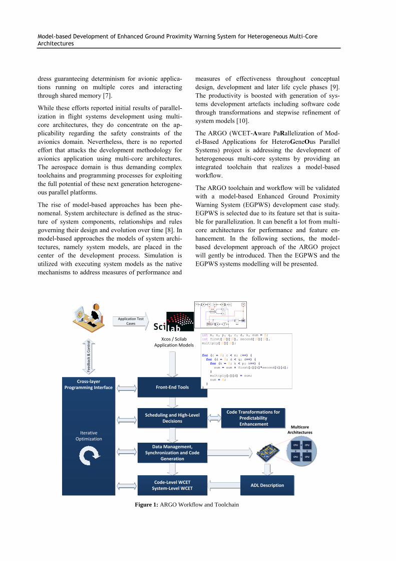
Figure 1: ARGO Workflow and Toolchain
Model-based Development of Enhanced Ground Proximity Warning System for Heterogeneous Multi-Core Architectures
2 Model-based Development Approach
for Heterogeneous Multi-Core Archi-
tectures
Model-based approaches propose the development of
models and generation of executable software entities
through successive model-to-model and model-to-text
transformations [11]. The model-based development
is a model-based approach that is characterized by the
seamless use of executable and graphical data flow
oriented block diagram models and state machines for
system specification, design and implementation,
employing modeling and simulation tools such as
Scilab/Xcos or MATLAB/Simulink [12].
The objective of the model-based development ap-
proach (Figure 1) of the ARGO project is to design,
implement and deploy hard real-time applications on
multi-core targets through parallel code generation
with top-notch Worst Case Execution Time (WCET)
analysis in a programming environment that will
guarantee efficiency and productivity. The approach
extends previous work to cover real-time applications
[13].
The model-based development environment allows
engineers to design a system from a high-level point
of view. Design models specify executable system
architecture. Model-in-the-Loop (MIL) simulations
are used for the early validation of the systems de-
sign. Code generation and code transformations are
performed with a strong objective of keeping the code
base predictable or warning the user as early as pos-
sible of possible problems in WCET estimation in the
current design. The targeted architecture, defined with
an Architecture Description Language (ADL), and
specific low level transformations ensure paralleliza-
tion with WCET constraints as tight as possible. Tar-
gets include any hardware platform with a parallel
programming model that can express time-predictable
computation and communication. Software-in-the-
Loop (SIL) simulations that also exploit target speci-
fications are used to advance the validation of the
design. In the ARGO project the approach will be
evaluated on the multi-core platform of Recore Sys-
tems, a specialist in flexible multi-core platforms and
subsystems IP [14]. Hardware-in-the-Loop (HIL)
simulations will be used to validate the performance
of the system.
Constant feedback is provided to the user at each
step. The possibility to select the transformations and
perform them in an interactive manner results in a
semi-automatic, guided process. The models are en-
riched with the results of the code generation, the real
time constraints analysis and x-in-the-loop simula-
tions, thus tracing and controlling the results of an
iteration of the process for early verification and
validation.
3 Enhanced Ground Proximity Warn-
ing System
EGPWS is a name that is used for current Terrain
Awareness and Warning Systems (TAWS) which aim
to prevent controlled flight into the terrain. There are
various TAWS options available in the market for
various platforms in various configurations. Exam-
ples may include EGPWS from Honeywell [15],
T2CAS from ACSS [16], LANDMARK™ from L3
[17] and TAWS from Universal Avionics [18]. A brief
comparison of these systems and more can be found
in [19].
The core feature set of EGPWS is to create visual and
aural warnings in order to avoid controlled flight into
the terrain. These warnings are categorized in 5
modes:
Mode 1: Excessive Descent Rate provides alerts for
excessive descent rates for all phases of flight.
Mode 2: Excessive Terrain Closure Rate provides
alerts to protect the aircraft from impacting the
ground when terrain is rising rapidly with respect to
the aircraft.
Mode 3: Altitude Loss After Take-off provides alerts
when a significant altitude loss is detected after take-
off or during a low altitude go around.
Mode 4: Unsafe Terrain Clearance provides alerts
when there is no sufficient terrain clearance regarding
the phase of the flight, aircraft configuration and
speed.
Mode 5: Excessive Deviation Below Glideslope pro-
vides alerts when the aircraft descends below the
glideslope.
The modes 1 to 5 are regarded as suitable for coarse
grain parallelization.
Additionally, an EGPWS provides some enhanced
functions based on a terrain database. These functions
are:
Terrain Awareness Display (TAD) provides an image
of the surrounding terrain represented in various
Model-based Development of Enhanced Ground Proximity Warning System for Heterogeneous Multi-Core Architectures
colors on the Navigation Display as well as the warn-
ings and cautions regarding the terrain interactions.
Terrain Clearance Floor (TCF) provides a low ter-
rain warning during landing and thus enhances the
basic functions with alerts for the descent below a
predefined “Terrain Clearance Floor” disregarding the
aircraft configuration.
The terrain processing and particularly collision de-
tection algorithms that are required for TAD and TCF
are regarded as candidates for fine grain paralleliza-
tion.
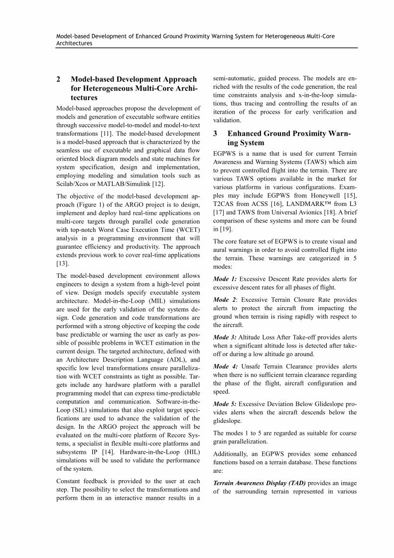
Figure 2: Top Level EGPWS Model
4 EGPWS Systems Modeling
Figure 2 shows the top level of the ARGO EGPWS
prototype model. The model is being developed using
the graphical modeling environment Scilab/Xcos
[20].
The ARGO EGPWS will be designed based on a
commercial system as it is deployed in DLR’s Ad-
vanced Technology Research Aircraft (ATRA).
Therefore, the development refers to the EGPWS
description in the A320’s Flight Crew Operating
Manual (FCOM; section 1.34.70 in [21]). ATRA’s
EGPWS is supplied by Honeywell.
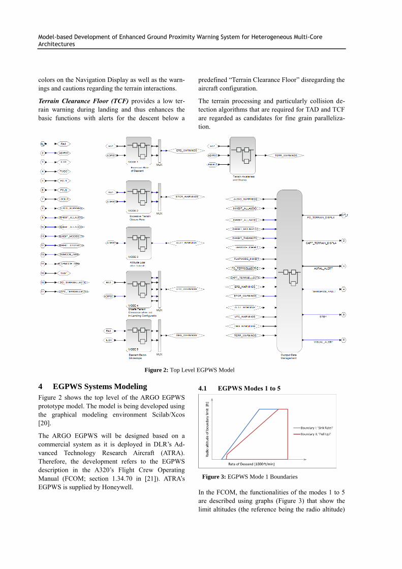
4.1 EGPWS Modes 1 to 5
Figure 3: EGPWS Mode 1 Boundaries
In the FCOM, the functionalities of the modes 1 to 5
are described using graphs (Figure 3) that show the
limit altitudes (the reference being the radio altitude)

Model-based Development of Enhanced Ground Proximity Warning System for Heterogeneous Multi-Core Architectures
associated with each mode as functions of other pa-
rameters like airspeed or rate of descent.
By using Xcos’ “Interpolation” blocks, those graphs
are modeled for the ARGO EGPWS. For an example
see Figure 4. An Interpolation block needs to be pro-
vided with two vectors for parametrization, one con-
taining a selection of input and the other a corre-
sponding number of output data points of the function
that has to be modeled. It is between these points that
the output matching a given input can then be inter-
polated.
Figure 4: Xcos Model of EGPWS Mode 1
Figure 4 shows the implementation of Mode 1 as a
model in Xcos. Mode 1 focuses on the aircraft’s Rate
Of Descend (ROD) within a medium proximity to the
terrain. For every ROD value, there is a limit altitude
associated to it. In this way, two different boundaries
are formed for Mode 1, each triggering a vocal alert
and illumination of a designated GPWS warning
lamp in the cockpit. When penetrated by sinking
below the limit altitude, the first boundary causes a
repetitive “SINK RATE!”, while the second one trig-
gers a more demanding “PULL UP!”. This alert is
also repeated until the aircraft climbs above the limit
altitude or reduces its ROD.
Each of the two boundaries is modeled using an In-
terpolation block, as can be seen in Figure 4. The
input, namely the aircraft’s ROD, is taken from a
signal vector (which simulates a data bus called
ADIRS1 - Air Data Inertial Reference System - in the
real A320) by utilizing an “Extractor” block. This
block allows extracting a single signal out of a bus or
multiplex signal.
The altitude limit obtained through the interpolation
is then compared to the aircraft’s actual radio altitude.
This is the signal from input port 1 in Figure 4. If its
value is lower than the computed limit, the signals
“ROD_warning” or “ROD_intense_warning” are set
to the value 1, which acts as a trigger to the associat-
ed vocal alert and the warning lamp.
The radio altitude signal runs through a “Saturation”
block which imposes limit values on a signal. It is
used here to make sure that Mode 1 does not give out
warnings when the aircraft is on ground. This is done
by limiting the signal value to 10 ft above ground
level and above.
4.2 Terrain Awareness Display and Terrain
Clearance Floor
The Terrain Awareness Display and Terrain Clearance
Floor features of an EGPWS need a terrain database
from which they can gather information about the
terrain surrounding the aircraft’s current position
during flight.
The 3D representation of the terrain is referred to as
Digital Elevation Model (DEM) [22]. It is available
as elevation data organized in the form of a matrix.
Regarding the increasing demand for DEMs with
global coverage, the Shuttle Radar Topography Mis-
sion (SRTM) provided global high quality DEMs at
resolution levels of 1 arc second (∼30 m) or 3 arc
second (∼90 m)[23]. The ARGO EGPWS terrain
databases are created using SRTM 3 arc second data.
Two-phase processing, namely broad phase and nar-
row phase, is a common approach in collision detec-
tion algorithms [24]. While the broad phase is used to
identify the particular terrain database segments to be
used, narrow phase uses these segments for calculat-
ing colors and their densities in the TAD as well as
the TAD and TCF warnings and cautions.
In broad phase, spatial partitioning techniques are
utilized for identifying the segments of the terrain
database to be processed. Uniform grids are used to
divide the terrain into equally sized regions that are
associated to a database segment. This way, an easy
and fast terrain data access mechanism is developed
for the given coordinates of the airplane. While the
initial grid size is selected as 1 degree, it will be fur-
ther tuned for optimizing the overall performance.
The TAD terrain picture and TCF are straight-forward
computation of the narrow phase in which the eleva-
tion of terrain data points is compared to the aircraft
as a point, either for collision as in TCF or for color
mapping as in the TAD terrain picture. However, the
warnings and cautions from the TAD algorithm re-
quire a relatively complex collision detection pro-
cessing: the vertical and horizontal terrain caution
and warning envelopes define two polygons. The
intersection of these polygons and the terrain is used

Model-based Development of Enhanced Ground Proximity Warning System for Heterogeneous Multi-Core Architectures
to trigger the related caution and warning messages.
The narrow phase is responsible for the collision
detection between caution and warning envelopes and
the terrain. A comprehensive survey of collision de-
tection algorithms can be found in [25]. Image-based
algorithms have been employed for making use of the
processing power of graphics cards [26]. The inter-
ference test is conducted based on a depth map and is
maintained in an image buffer which is generated by
projecting the object on a plane. In the ARGO
EGPWS vertical ray casting is employed in points of
the terrain database and the depth map of the terrain
caution and warning envelopes is then compared to
the elevation data of the particular point to identify
the collision (Figure 5).
Figure 5: Collision Detection Approach
As opposed to the model elements that represent the
ARGO EGPWS modes, which are purely Xcos based,
the TAD and TCF algorithms are being developed
using Scilab scripts and are integrated to the Xcos
model as a user defined block.
4.3 Output Data Management
According to the current system architecture, the
modes 1 to 5 as well as the terrain functions TAD and
TCF reside in separate Xcos blocks. In addition, there
is a block containing the Output Data Management,
which evaluates its inputs in order to create triggers
for the appropriate visual and aural warnings.
The core of the Output Data Management is an algo-
rithm that applies a priority list to the trigger signals.
This is done to avoid several alerts being active at the
same time in the case of more than one trigger signal
having the value 1.
The entire trigger signals being used in the ARGO
EGPWS and the modes to which they belong are
listed in Table 1. Although the modes are designed to
detect different critical situations, the pilot’s task is
always the same: avoid impacting the terrain, either
by a change of course or, especially after urgent
warnings, by pulling up and gaining altitude. For this
reason, some of the vocal cues are the same and can
thus share the same level of priority, making the algo-
rithm less complex.
Table 1: Names of trigger signals in the ARGO EGPWS and their respective vocal cues
Nr. Mode name of trigger signal vocal cue situation priority
1. 1
ERD_warning Sink rate! always 2
2. ERD_intense_warning Pull up! always 1
3.
2
ETCRa_warning Terrain! always 6
4. ETCRb_warning Terrain! always 6
5. ETCR_intense_warning Pull up! always 1
6. 3 ALAT_warning Don't sink! take-off 7
7.
4
UTCa_warning Too low, terrain! cruise/approach 5
8. UTCa_gear_warning Too low, gear! cruise/approach 4
9. UTCb_warning Too low, terrain! cruise/approach 5
10. UTCb_flaps_warning Too low, flaps! cruise/approach 4
11. UTCc_warning Too low, terrain! take-off 3
12. 5
DBG_warning Glideslope! approach 8
13. DBG_intense_warning GLIDESLOPE! approach 7
14. TAD
TAD_caution Terrain ahead! always 5
15. TAD_warning Terrain ahead, pull up! always 1
16. TCF TCF_warning Too low, terrain! cruise/approach 5

Model-based Development of Enhanced Ground Proximity Warning System for Heterogeneous Multi-Core Architectures
Table 2: Priority rating of signals in Table 1and assignment to the main phases of flight
situation: take-off / missed approach cruise approach / landing
priority:
1 ETCR_intense_warning ETCR_intense_warning ETCR_intense_warning
ERD_intense_warning ERD_intense_warning ERD_intense_warning
TAD_warning TAD_warning TAD_warning
2 ERD_warning ERD_warning ERD_warning
3 UTCc_warning
4 UTCb_flaps_warning UTCb_flaps_warning UTCb_flaps_warning
UTCa_gear_warning UTCa_gear_warning UTCa_gear_warning
5 UTCb_warning UTCb_warning UTCb_warning
UTCa_warning UTCa_warning UTCa_warning
TCF_warning TCF_warning TCF_warning
TAD_caution TAD_caution TAD_caution
6 ETCRa_warning ETCRa_warning ETCRa_warning
ETCRb_warning ETCRb_warning ETCRb_warning
7
DBG_intense_warning
ALAT_warning
8
DBG_warning
Table 3: Abbreviations in signal names in Table 1 and Table 2
Abbreviation Explanation Abbreviation Explanation
ALAT Altitude Loss After Take-Off TAD Terrain Awareness Display
DBG Deviation Below Glideslope TCF Terrain Clearance Floor
ERD Excessive Rate of Descent UTC Unsafe Terrain Clearance
ETCR Excessive Terrain Closure Rate
Table 2 lists the trigger signals again, organized by
their level of priority and assigned to the phases of
flight in which they are relevant. This serves to point
out that the warnings of Mode 3 (Altitude Loss After
Take-off) and Mode 5 (Excessive Deviation Below
Glideslope), which are designed specifically for take-
off and approach, respectively, are considered less
urgent in the ARGO EGPWS than the warnings de-
signed for the whole flight envelope. Furthermore,
the highest priorities are given to the warnings that
directly demand the pilot to pull up.
Table 3 presents the explanations for the abbrevia-
tions used in the signal names in Table 1 and Table 2.
The algorithm will also handle additional influences
on the triggering of alerts, such as pushbuttons in the
cockpit that allow the pilot to alter the EGPWS set-
tings to his needs. For example, there are two buttons
in the overhead panel which are labeled “SYS –
OFF” and “G/S MODE – OFF”. Their purpose is to
disable all of the EGPWS Modes or just Mode 5,
respectively. Other buttons may inhibit the use of
aural alerts, leaving only the optical cues to catch the
pilot’s attention.
The logic that is represented in the tables will be
modeled using state machines which are implemented
in Scilab/Xcos as Automata (finite-state machine)
block [27].
Conclusion
After introducing the recent advance on heterogene-
ous multi-core architectures in avionics, the paper
gently presents the model-based development ap-
proach of the ARGO project. This approach is being
exercised in the development of ARGO Enhanced
Ground Proximity Warning System due the suitability
of its feature set for parallelization.
In the modeling, modes and Output Data Manage-
ment are developed using Xcos, while Scilab script-
ing is used for the Terrain Awareness Display and
Terrain Clearance Floor calculations. Thereby we aim

Model-based Development of Enhanced Ground Proximity Warning System for Heterogeneous Multi-Core Architectures
at evaluating diverse model-based parallel application
development capabilities of the ARGO approach.
As the initial prototype of the system model has been
constructed, the future work will include x-in-the-
loop testing. The first step will be from model-in-the-
loop testing which will be eventually followed by
software-in-the loop and hardware-in-the loop testing
with the utilization of the ARGO toolchain for code
generation.
5 Acknowledgement
This work was supported in part by the European
Union’s Horizon 2020 Research and Innovation Pro-
gramme under grant agreement No 688131 — AR-
GO.Action. www.argo-project.eu
6 References
[1] P. J. Prisaznuk. Integrated modular avionics.
Proceedings of the IEEE 1992 National Aero-
space and Electronics Conference, pp.39-45,
1992.
[2] C. B. Watkins, and Randy Walter. Transition-
ing from federated avionics architectures to in-
tegrated modular avionics. IEEE/AIAA 26th
Digital Avionics Systems Conference, pp. 2-A,
2007.
[3] J. Nowotsch and M. Paulitsch. Leveraging
multi-core computing architectures in avion-
ics. 9th
European Dependable Computing
Conference (EDCC), pp. 132-143, 2012.
[4] H. Karray, M. Paulitsch, B. Koppenhöfer, and
D. Geiger. Design and implementation of a
degraded vision landing aid application on a
multicore processor architecture for safety-
critical application. 16th International Sympo-
sium on Object/Component/Service-Oriented
Real-Time Distributed Computing (ISORC),
pp. 1-8, 2013
[5] B. Koppenhöfer, and D. Geiger. EMC2 Use
Case:Hybrid Avionics Integrated Architecture
Demonstrator. HiPEAC, Workshop EMC²,
2016.
[6] H. Agrou , P. Sainrat, M. Gatti, and P. Toillon.
Mastering the behavior of multi-core systems
to match avionics requirements. AIAA 31st
Digital Avionics Systems Conference (DASC),
pp.6E5-1, 2012.
[7] A. Löfwenmark, and S. Nadjm-Tehrani. Chal-
lenges in future avionic systems on multi-core
platforms. International Symposium on Soft-
ware Reliability Engineering Workshops
(ISSREW).pp.115-119, 2014.
[8] A. Tolk, and T.K. Hughes. Systems engineer-
ing, architecture, and simulation. In: Modeling
and Simulation-based Systems Engineering
Handbook, Editors: D. Gianni, A. D'Ambro-
gio, and A. Tolk. CRC Press, pp. 11-41, 2014.
[9] INCOSE, Vision 2020. No. INCOSE-TP-2004-
004-02, INCOSE, 2007.
[10] C. Atkinson and T. Kühne. Model-driven de-
velopment: a metamodeling foundation. IEEE
Software, Vol. 20, No. 5, pp. 36-41, 2003.
[11] D. Gasevic, D. Djuric, and V. Devedic. Model
driven engineering and ontology development.
Springer Science & Business Media, 2009.
[12] I. Stürmer, M. Conrad, I Fey and H Dörr. Ex-
periences with model and autocode reviews in
model-based software development. Proceed-
ings of the 2006 International Workshop on
Software Engineering for Automotive Sys-
tems, pp. 45-52, 2006.
[13] T. Stripf, O. Oey, T Bruckschloegl, J. Becker,
G. Rauwerda, K. Sunesen, G. Goulas, P.
Alefragis, N.S. Voros, S. Derrien, and O.
Sentieys. Compiling Scilab to high perfor-
mance embedded multicore systems. Micro-
processors and Microsystems, Vol.37, No. 8,
pp.1033-1049, 2013.
[14] L. Berrojo, R. Moreno, R. Regada, E. Garcia,
R. Trautner, G. Rauwerda, K. Sunesen, Y. He,
S. Redant, G. Thys, and J. Andersson. Scalable
sensor data processor: a multi-core payload
data processor ASIC. The international Space
System Engineering Conference DASIA, in
Barcelona, Spain, 2015.
[15] Honeywell. Terrain and Traffic Awareness.
Retrieved March 16, 2016 from
https://aerospace.honeywell.com/en/product-
listing/terrain-and-traffic-awareness
[16] ACSS. T2CAS. Retrieved March 16, 2016
from www.acss.com/products/t2cas/
[17] L3. LANDMARK™ Terrain Awareness &
Warning Systems. Retrieved March 16, 2016

Model-based Development of Enhanced Ground Proximity Warning System for Heterogeneous Multi-Core Architectures
from www.l-
3avionics.com/products/landmark/
[18] Universal Avionics. TAWS | Terrain Awareness
and Warning System. Retrieved March 16,
2016 from
www.uasc.com/home/shop/avionics/taws
[19] D. Smith. Traffic Alert Collision Avoidance
Systems—TCAS Buyer’s Guide. Pilot’s Guide
to Avionics 2005, pp. 34-41, 2005.
[20] S.L. Campbell, J.P. Chancelier, and R. Nikou-
khah. Modeling and Simulation in Scil-
ab/Scicos. Springer New York, 2006.
[21] Airbus Industries S.A.S., A320 Flight Crew
Operating Manual, System Description 1;
REV 24, AI Toulose.
[22] Z. Li, C. Zhu, and C. Gold. Digital terrain
modeling: principles and methodology. CRC
Press, 2004.
[23] B. Rabus, M. Eineder, A. Roth, and R. Bamler.
The shuttle radar topography mission—a new
class of digital elevation models acquired by
spaceborne radar. ISPRS Journal of Photo-
grammetry and Remote Sensing, Vol.57, No.4,
pp.241-262, 2003.
[24] C. Ericson. Real-time collision detection. CRC
Press, 2004.
[25] M. Lin, and S. Gottschalk. Collision detection
between geometric models: A survey. Proceed-
ings of IMA Conference on Mathematics of
Surfaces Vol. 1, pp. 602-608, 1998.
[26] G. Baciu, W.S.K. Wong. Image-based Colli-
sion Detection, In: Integrated Image and
Graphics Technologies, Springer, 75-94, 2006.
[27] M. Najafi, and R. Nikoukhah. Implementation
of hybrid automata in Scicos. 2007 IEEE In-
ternational Conference on Control Applica-
tions, pp. 819-824, 2007.