Model-Based A-Posteriori Integration of Engineering Tools ...
18
Software and Systems Modeling manuscript No. (will be inserted by the editor) Model-Based A-Posteriori Integration of Engineering Tools for Incremental Development Processes Simon M. Becker, Thomas Haase, Bernhard Westfechtel Department of Computer Science III - University of Technology Aachen Received: date / Revised version: date Abstract A-posteriori integration of heterogeneous engi- neering tools supplied by different vendors constitutes a chal- lenging task. In particular, this statement applies to incremen- tal development processes where small changes have to be propagated — potentially bidirectionally — through a set of inter-dependent design documents which have to be kept con- sistent with each other. Responding to these challenges, we have developed an approach to tool integration which puts strong emphasis on software architecture and model-driven development. Starting from an abstract description of a soft- ware architecture, the architecture is gradually refined down to an implementation level. To integrate heterogeneous engi- neering tools, wrappers are constructed for abstracting from technical details and for providing homogenized data access. On top of these wrappers, incremental integration tools pro- vide for inter-document consistency. These tools are based on graph models of the respective document classes and graph transformation rules for maintaining inter-document consis- tency. Altogether, the collection of support tools and the re- spective infrastructure considerably leverage the problem of composing a tightly integrated development environment from a set of heterogeneous engineering tools. 1 Introduction Development processes in different engineering disciplines are hard to support. Throughout the development process, a large number of documents are created which constitute the inputs and outputs of development tasks. These documents describe the product to be developed from different perspec- tives and at different levels of abstractions. They are con- nected by manifold dependencies and have to kept consis- tent with each other. In this respect, it has to be taken into account that development processes often are highly incre- mental: Rather than creating documents in a phase-oriented order, activities in different phases are performed in an in- tertwined way, implying that small changes have to be prop- agated back and forth between inter-dependent documents. While this constitutes a major challenge in its own, a further complication results from the fact that different documents may be processed by heterogeneous tools supplied by differ- ent vendors. A-posteriori integration of heterogeneous tools requires highly sophisticated modeling and implementation techniques in order to construct a development environment for incremental development processes with feasible effort. In response to these challenges, we have developed an ap- proach to tool integration which puts strong emphasis on soft- ware architecture and model-driven development. The term “approach” is not confined to the conceptual level, i.e., we have not merely defined concepts for tool integration. Rather, we have realized our approach by a collection of support tools and a respective tool infrastructure. In this way, we consider- ably leverage the problem of composing a tightly integrated development environment from a set of heterogeneous engi- neering tools. This is achieved through a model-based tool construction process which consists of the following steps: 1. Architecture modeling and refinement (Section 3). The software architecture of the integrated development en- vironment to be constructed is modeled initially at a high level of abstraction. The initial architecture is refined grad- ually by means of architectural transformations which take care of technical details and introduce technical compo- nents such as tool wrappers required to make integration work. The transformation process results in a concrete ar- chitecture consisting of the components which need to be implemented (either manually or automatically). 2. Modeling and construction of wrappers (Section 4). In the case of a-posteriori integration, we have to deal with tools supplied by different vendors, using different data management systems, etc. To make use of these tools, we have to provide components which abstract from techni- cal details and make them available at a conceptual level. These components, which are called wrappers, are con- structed in a semi-automatic way with an interactive tool which supports the exploration of the interface of the de- velopment tool to be integrated. 3. Construction of executable models for incremental con- sistency management (Section 5). By providing tool wrap-
Transcript of Model-Based A-Posteriori Integration of Engineering Tools ...
Software and Systems Modeling manuscript No.(will be inserted by the editor)
Model-Based A-Posteriori Integration of Engineering Tools for IncrementalDevelopment Processes
Simon M. Becker, Thomas Haase, Bernhard Westfechtel
Department of Computer Science III - University of Technology Aachen
Received: date / Revised version: date
Abstract A-posteriori integration of heterogeneous engi-neering tools supplied by different vendors constitutes a chal-lenging task. In particular, this statement applies to incremen-tal development processes where small changes have to bepropagated — potentially bidirectionally — through a set ofinter-dependent design documents which have to be kept con-sistent with each other. Responding to these challenges, wehave developed an approach to tool integration which putsstrong emphasis on software architecture and model-drivendevelopment. Starting from an abstract description of a soft-ware architecture, the architecture is gradually refined downto an implementation level. To integrate heterogeneous engi-neering tools, wrappers are constructed for abstracting fromtechnical details and for providing homogenized data access.On top of these wrappers, incremental integration tools pro-vide for inter-document consistency. These tools are based ongraph models of the respective document classes and graphtransformation rules for maintaining inter-document consis-tency. Altogether, the collection of support tools and the re-spective infrastructure considerably leverage the problem ofcomposing a tightly integrated development environment froma set of heterogeneous engineering tools.
1 Introduction
Development processes in different engineering disciplinesare hard to support. Throughout the development process, alarge number of documents are created which constitute theinputs and outputs of development tasks. These documentsdescribe the product to be developed from different perspec-tives and at different levels of abstractions. They are con-nected by manifold dependencies and have to kept consis-tent with each other. In this respect, it has to be taken intoaccount that development processes often are highly incre-mental: Rather than creating documents in a phase-orientedorder, activities in different phases are performed in an in-tertwined way, implying that small changes have to be prop-agated back and forth between inter-dependent documents.
While this constitutes a major challenge in its own, a furthercomplication results from the fact that different documentsmay be processed by heterogeneous tools supplied by differ-ent vendors. A-posteriori integration of heterogeneous toolsrequires highly sophisticated modeling and implementationtechniques in order to construct a development environmentfor incremental development processes with feasible effort.
In response to these challenges, we have developed an ap-proach to tool integration which puts strong emphasis on soft-ware architecture and model-driven development. The term“approach” is not confined to the conceptual level, i.e., wehave not merely defined concepts for tool integration. Rather,we have realized our approach by a collection of support toolsand a respective tool infrastructure. In this way, we consider-ably leverage the problem of composing a tightly integrateddevelopment environment from a set of heterogeneous engi-neering tools. This is achieved through a model-based toolconstruction process which consists of the following steps:
1. Architecture modeling and refinement (Section 3). Thesoftware architecture of the integrated development en-vironment to be constructed is modeled initially at a highlevel of abstraction. The initial architecture is refined grad-ually by means of architectural transformations which takecare of technical details and introduce technical compo-nents such as tool wrappers required to make integrationwork. The transformation process results in a concrete ar-chitecture consisting of the components which need to beimplemented (either manually or automatically).
2. Modeling and construction of wrappers (Section 4). Inthe case of a-posteriori integration, we have to deal withtools supplied by different vendors, using different datamanagement systems, etc. To make use of these tools, wehave to provide components which abstract from techni-cal details and make them available at a conceptual level.These components, which are called wrappers, are con-structed in a semi-automatic way with an interactive toolwhich supports the exploration of the interface of the de-velopment tool to be integrated.
3. Construction of executable models for incremental con-sistency management (Section 5). By providing tool wrap-
2 Simon M. Becker et al.
BemView
COMOSPT
COMOSPT Aspen
Plus
AspenPlus
CheopsMOREX
Fl ieß bi ldw e rkz eu g
FB-Datenm odellFB-Datenm odell
erw
eiterte
Basisfu
nktio
nalitä
ten
erw
eiterte
Basisfu
nktio
nalitä
ten
VISIO
Prozessintegrations-W rapper
Prozessintegrations-W rapper
Prozessm aschineProzessm aschine
Prozess-fragm ente
und-spuren
Prozess-fragm ente
und-spuren
weitere prozess-integrierte W erkzeuge
Situations-analysePD W
Situations-analysePDW
6 APIs fürProzessintegration, z.B.- Akt ionsaktivierung- Kom mando-
einschränkungz.B.- F ließbildverfeinerung- Navigation
VISIO
Adm inistrations-system (B4)
PRIM E-externeKomponenten
Fließbild-ASPEN PlusIntegrator(B2)
M orex (A3)
Entscheidungs-dokum entation
ProcessGuide
ProcessTracer
PrimeAHEAD
Betriebssystem
Audio-ToolVideo-Tool Whiteboard Event-Sharing
Konferenzmanagementsystem
Multicast
KomPaktIntegration ToolIntegration Tool
New tools
Existing engineering tools
Fig. 1 Integrated tool environment
pers, we decompose the problem of tool integration intomanageable pieces. In the third (and final) step, we de-velop integration tools for incremental consistency man-agement which make use of the wrappers’ interfaces. Here,we follow a model-based approach: First, the documentsto be integrated are described by corresponding documentmodels. Subsequently, an integration model is constructedwhich defines correspondences between documents andrules for maintaining inter-document consistency. The in-tegration model, which is based on graphs and graph trans-formations, is executable. In this way, we manage to con-struct integration tools with acceptable effort.
The rest of this paper is structured as follows: Section 2provides an overview of our approach. Sections 3–5, whichconstitute the core part of this paper, are devoted to the stepsof the model-based tool construction process. Section 6 dis-cusses related work. Finally, Section 7 concludes this paper.
2 Overview
2.1 Context
Although our tool integration approach is generic (it may beapplied in different engineering disciplines), it has been de-veloped in the context of a research project which is con-cerned with a specific domain. The Collaborative Researchcenter IMPROVE [NM97], a long-term research project car-ried out at Aachen University of Technology, deals with de-sign processes in chemical engineering. The mission of thisproject is to develop models and tools for supporting designprocesses in chemical engineering, focusing on early phases(conceptual design and basic engineering).
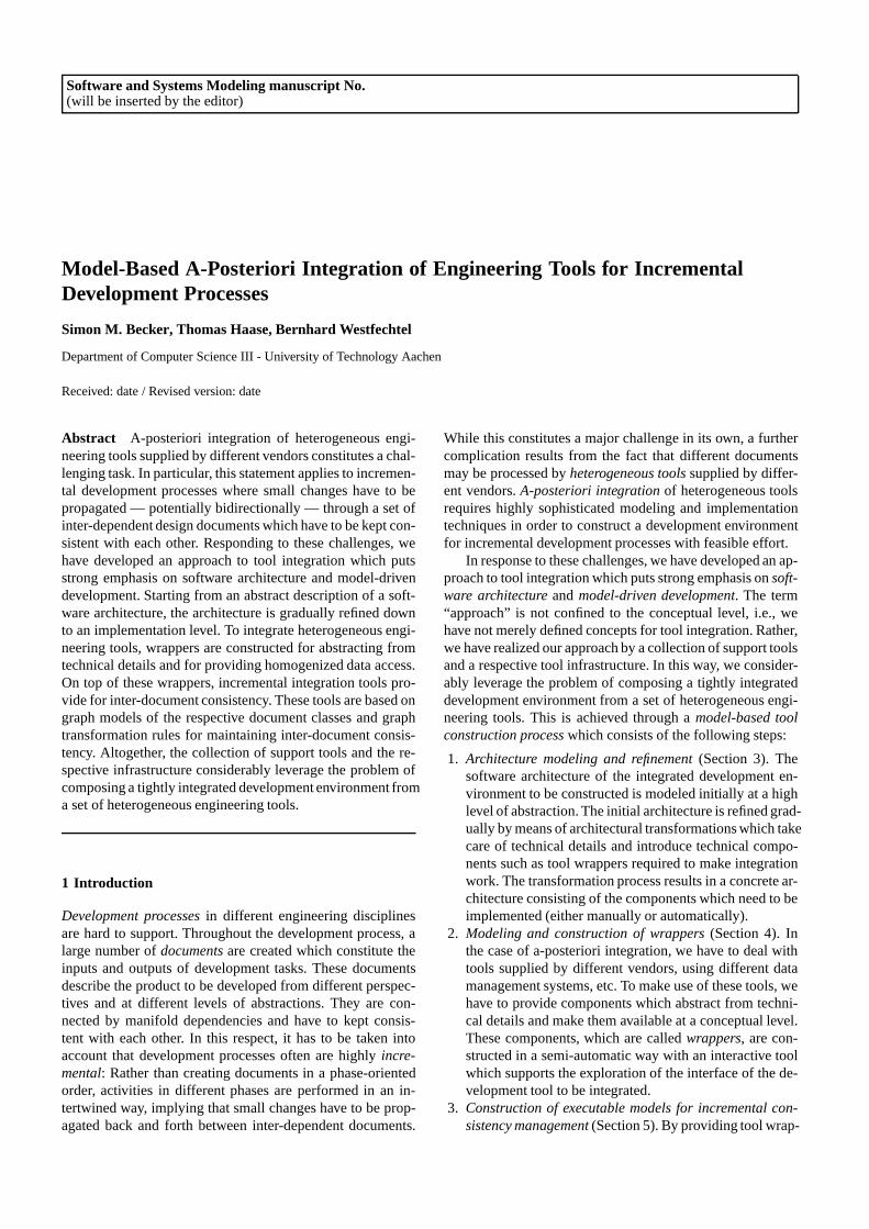
Figure 1 illustrates the overall vision of IMPROVE withrespect to tool support for the engineering design process1.
1 In the sequel, we prefer the term “design” to the term “devel-opment” when referring to chemical engineering because it is moreappropriate in that context. On the other hand, we will continue touse the term “development” in the context of software engineering(development of tools for chemical engineers).
PFR Flashing
Splitting
HE PFR
HEATER
RPlug
REQUIL HEATER
FLASH
SPLIT RPlug REQUIL
L L L L L L L L L
1.)
2.)
3.b)
3.a)
4.)
flow sheet
simulation model propagation of structure propagation of attributes
HE
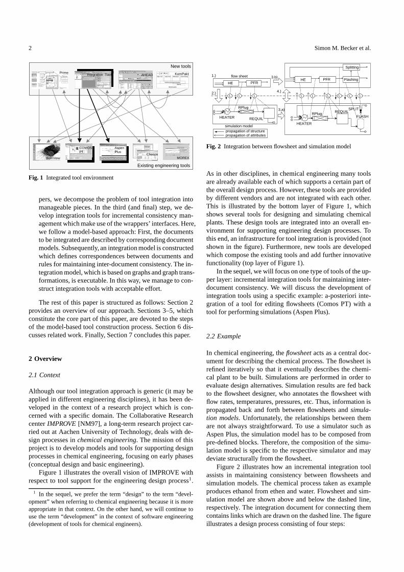
Fig. 2 Integration between flowsheet and simulation model
As in other disciplines, in chemical engineering many toolsare already available each of which supports a certain part ofthe overall design process. However, these tools are providedby different vendors and are not integrated with each other.This is illustrated by the bottom layer of Figure 1, whichshows several tools for designing and simulating chemicalplants. These design tools are integrated into an overall en-vironment for supporting engineering design processes. Tothis end, an infrastructure for tool integration is provided (notshown in the figure). Furthermore, new tools are developedwhich compose the existing tools and add further innovativefunctionality (top layer of Figure 1).
In the sequel, we will focus on one type of tools of the up-per layer: incremental integration tools for maintaining inter-document consistency. We will discuss the development ofintegration tools using a specific example: a-posteriori inte-gration of a tool for editing flowsheets (Comos PT) with atool for performing simulations (Aspen Plus).
2.2 Example
In chemical engineering, the flowsheet acts as a central doc-ument for describing the chemical process. The flowsheet isrefined iteratively so that it eventually describes the chemi-cal plant to be built. Simulations are performed in order toevaluate design alternatives. Simulation results are fed backto the flowsheet designer, who annotates the flowsheet withflow rates, temperatures, pressures, etc. Thus, information ispropagated back and forth between flowsheets and simula-tion models. Unfortunately, the relationships between themare not always straightforward. To use a simulator such asAspen Plus, the simulation model has to be composed frompre-defined blocks. Therefore, the composition of the simu-lation model is specific to the respective simulator and maydeviate structurally from the flowsheet.
Figure 2 illustrates how an incremental integration toolassists in maintaining consistency between flowsheets andsimulation models. The chemical process taken as exampleproduces ethanol from ethen and water. Flowsheet and sim-ulation model are shown above and below the dashed line,respectively. The integration document for connecting themcontains links which are drawn on the dashed line. The figureillustrates a design process consisting of four steps:
Model-Based A-Posteriori Integration of Engineering Tools for Incremental Development Processes 3
1. An initial flowsheet is created in Comos PT. This flow-sheet is still incomplete, i.e., it describes only a part ofthe chemical process (heating of substances and reactionin a plug flow reactor, PFR).
2. The integration tool is used to transform the initial flow-sheet into a simulation model for Aspen Plus. Here, theuser has to perform two decisions. While the heating stepcan be mapped structurally 1:1 into the simulation model,the user has to select the most appropriate block for thesimulation to be performed. Second, there are multiple al-ternatives to map the PFR. Since the most straightforward1:1 mapping is not considered sufficient, the user decidesto map the PFR into a cascade of two blocks. These deci-sions are made by selecting among the different possibil-ities of rule applications the tool presents to the user.
3. The simulation is performed in Aspen Plus, resulting in asimulation model which is augmented with simulation re-sults. In parallel, the flowsheet is extended with the chem-ical process steps that have not been specified so far (flash-ing and splitting).
4. Finally, the integration tool is used to synchronize the par-allel work performed in the previous step. This involvesinformation flow in both directions. First, the simulationresults are propagated from the simulation model backto the flowsheet. Second, the extensions are propagatedfrom the flowsheet to the simulation model. After thesepropagations have been performed, mutual consistency isre-established.
From this example, we may derive several features of thekinds of integration tools that we are addressing. Concerningthe mode of operation, our focus lies on incremental integra-tion tools rather than on tools which operate in a batch-wisefashion. Rather than transforming documents as a whole, in-cremental changes are propagated — in general in both direc-tions — between inter-dependent documents. Often, the inte-gration tool cannot operate automatically because the trans-formation process is non-deterministic. Then, the user hasto resolve non-deterministic choices interactively. In general,the user also maintains control on the time of activation, i.e.,the integration tool is invoked to re-establish consistency when-ever appropriate. Finally, it should be noted that integrationtools do not merely support transformations. In addition, theyare used for analyzing inter-document consistency or brows-ing along the links between inter-dependent documents.
A-posteriori integration constitutes an important challengebeing addressed by our approach. For example, it is crucialthat chemical engineers may continue to use their favoritetools for flowsheet design and simulation. In our case study,we assume two wide-spread commercial tools, namely Co-mos PT (for flowsheet design) and Aspen Plus (for simula-tion). Both tools are fairly typical with respect to their techni-cal features: Both maintain proprietary databases for storingflowsheet designs and simulation models, respectively. In ad-dition, they both offer COM interfaces for tool integration.These interfaces allow to query the respective tool’s func-tionality as well as to invoke operations to read and manipu-
Integrator Core
Integration Document
Rule Definitions
Correspondency Definition Tool
User Interface
Integrator
ASPEN
Aspen Wrapper
COMOS
Comos Wrapper
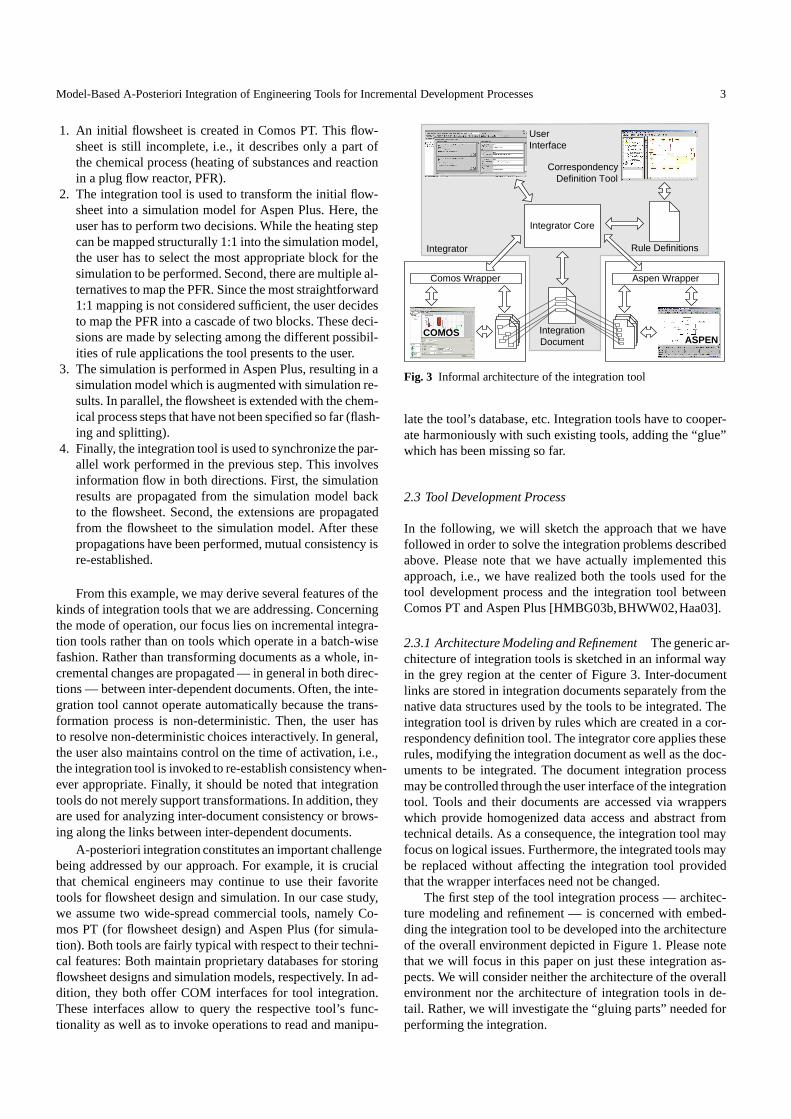
Fig. 3 Informal architecture of the integration tool
late the tool’s database, etc. Integration tools have to cooper-ate harmoniously with such existing tools, adding the “glue”which has been missing so far.
2.3 Tool Development Process
In the following, we will sketch the approach that we havefollowed in order to solve the integration problems describedabove. Please note that we have actually implemented thisapproach, i.e., we have realized both the tools used for thetool development process and the integration tool betweenComos PT and Aspen Plus [HMBG03b,BHWW02,Haa03].
2.3.1 Architecture Modeling and Refinement The generic ar-chitecture of integration tools is sketched in an informal wayin the grey region at the center of Figure 3. Inter-documentlinks are stored in integration documents separately from thenative data structures used by the tools to be integrated. Theintegration tool is driven by rules which are created in a cor-respondency definition tool. The integrator core applies theserules, modifying the integration document as well as the doc-uments to be integrated. The document integration processmay be controlled through the user interface of the integrationtool. Tools and their documents are accessed via wrapperswhich provide homogenized data access and abstract fromtechnical details. As a consequence, the integration tool mayfocus on logical issues. Furthermore, the integrated tools maybe replaced without affecting the integration tool providedthat the wrapper interfaces need not be changed.
The first step of the tool integration process — architec-ture modeling and refinement — is concerned with embed-ding the integration tool to be developed into the architectureof the overall environment depicted in Figure 1. Please notethat we will focus in this paper on just these integration as-pects. We will consider neither the architecture of the overallenvironment nor the architecture of integration tools in de-tail. Rather, we will investigate the “gluing parts” needed forperforming the integration.
4 Simon M. Becker et al.
To this end, we essentially refine the wrapper componentsdisplayed in the informal architecture of Figure 3. In fact, itturns out that the refinement results in a fairly sophisticatedsubsystem which is designed systematically by applying ar-chitectural transformations. Here, we distinguish between alogical architecture abstracting from technical details and aconcrete architecture which realizes the logical architecture.Starting from a high-level simple architectural configuration,wrappers are introduced and decomposed, resulting in a re-fined logical architecture (Figure 5). Subsequently, the logi-cal architecture is further refined into a concrete architecturewhich eventually takes care of all of the details of the under-lying technical infrastructure (Figure 6).
2.3.2 Interactive Modeling and Construction of WrappersIn the previous step, the architecture is refined such that theproblem of wrapper construction is decomposed into two lev-els. Technical wrappers are responsible for hiding the tech-nical details of the interfaces provided by the tools. For ex-ample, the clients of technical wrappers are shielded fromthe underlying communication infrastructure such as COMor CORBA. This is illustrated in Figure 7 for the wrapper ofAspen Plus, which provides a COM interface.
Apart from this abstraction, the operations provided bythe tools are mapped 1:1 onto the interface of the technicalwrapper. In contrast, the homogenizer wrapper located on topof the technical wrapper realizes the data abstraction requiredby the integration tool. In our running example, both flow-sheets and simulation models can be mapped onto a commonmeta model, namely process flow diagrams (PFDs) [Bay03].The wrapper establishes a view which is based on the PFDmeta model. For example, Aspen Plus documents are mod-eled in terms of ports and components (Figure 8).
The method implementations for the homogenizer wrap-per may be constructed in a semi-automatic way in the caseof tools providing a COM interface (Figures 9–11). To thisend, the implementer of the wrapper executes a method in-teractively through the COM interface. Method invocationsare traced and visualized by sequence diagrams, which theimplementer generalizes into method implementations.
2.3.3 Executable Models for Incremental Consistency Man-agement So far, we have considered the development ofwrappers for accessing the tools to be integrated as well astheir documents. Now, we address the adaptation of the inte-gration tool, which makes use of the homogenizer wrappers.As illustrated in Figure 3, the integration tool consists of ageneric core which is driven by domain-specific rules. Theserules are defined with the help of the UML. Executable rulesare constructed as follows (Figure 13):
1. The integration tool is based on a generic meta modelwhich defines graph-based documents as well as the con-tents of integration documents. If required, the meta modelmay be extended to define base concepts for a specific do-main. For the integration of COMOS PT and Aspen Plus,we have defined the PFD meta model as a common meta
model. In this way, integration rules may be expressed interms of this meta model. Moreover, the PFD meta modeldetermines the interface of the homogenizer wrapper.
2. Documents are integrated on the type level by defininglink types which relate types of increments being partsof the respective documents (Figure 15). To define theselink types, the type hierarchies of the related documentsare retrieved through the homogenizer interface and aremade available in the correspondency definition tool.
3. On the abstract instance level, link templates relate corre-sponding patterns of the related documents. Initially, linktemplates are modeled as object diagrams (static collab-oration diagrams, Figure 16). Subsequently, they are re-fined by adding dynamic information. In this way, linkingrules are constructed which describe graph transforma-tions by dynamic collaboration diagrams (Figure 17).
4. Finally, linking rules are converted into an executable form.Then, a generic integration algorithm realized as part ofthe integrator core executes them (Figure 18). The inte-gration algorithm operates interactively: The user of theintegration tool is provided with a set of applicable rulesto resolve conflicts and non-determinism; unique rules areexecuted automatically to reduce user interactions.
2.3.4 Discussion So far, we have described the architecture-and model-based integration tool development process in asimplified way as a sequence of three steps. However, the ac-tual process may deviate from this simplified structure in thefollowing ways:
Reuse. The development process need not be performed fromscratch for each integration tool to be developed. Rather,results of previous processes may be reused. For exam-ple, the architectural patterns created through architec-tural modeling and refinement may be reused, in a po-tentially adapted way, from previous developments.
Parallelism. Some steps of the development process may beexecuted in parallel. For example, wrapper construction(Step 2) and development of executable integration rules(Step 3) may proceed in parallel after the interfaces of thehomogenizer wrappers have been negotiated and fixed.
3 Architecture Modeling and Refinement
3.1 Overview
Ordinarily, the term software architecture is defined as a de-scription of “the structure of the components of a program/sys-tem (and) their interrelationships” [GP95]. This descriptionserves different purposes, among other things e.g. analyzingcertain software qualities, such as adaptability, maintainabil-ity, or portability, or managing the software development pro-cess [BK99]. What this simple definition disregards, whendeveloping a large, complex system as it was introduced inSubsection 2.1, more than one structural perspective togetherwith the dependencies among them will be necessary withrespect to the goals mentioned above. These structural views,
Model-Based A-Posteriori Integration of Engineering Tools for Incremental Development Processes 5
for example, include a conceptual, a development, and a pro-cess view [CN96]. Therefore, “high-level”-diagrams as in Fig-ure 1 or Figure 3 are helpful to get a first impression of theoverall systems structure, but are not an adequate descriptionof a software system in the sense of a software architecture.
Node Edge
1 *
Architecture Component
Architecture Edge
Uses
Contains
Communication
Application Integrates
Document
Wrapper
NodeEnd 1 2
1 2
1 *
IntegratorEnd
1 *
1 1
ApplicationEnd 1
1 1
*
1
0..1
ApplicationWrapper
Integrator
ArchitectureNode Architecture NodeEnd
realization {and}
Fig. 4 Logical architecture meta model (cutout)
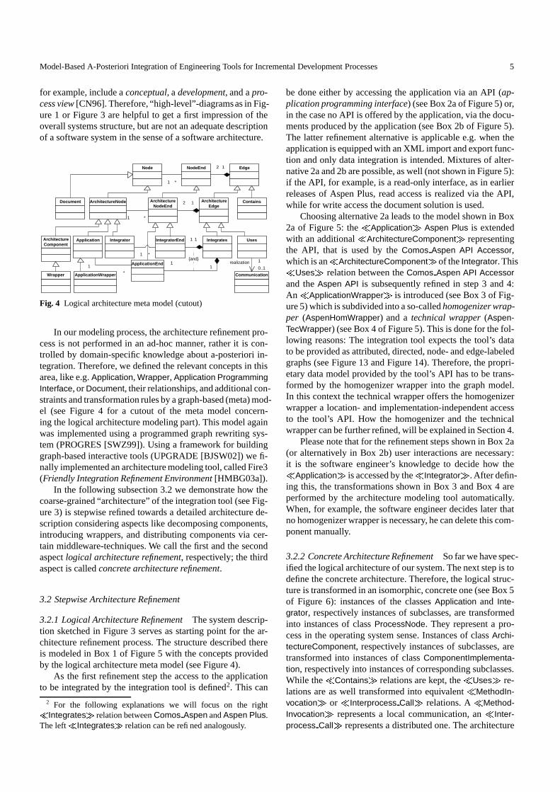
In our modeling process, the architecture refinement pro-cess is not performed in an ad-hoc manner, rather it is con-trolled by domain-specific knowledge about a-posteriori in-tegration. Therefore, we defined the relevant concepts in thisarea, like e.g. Application, Wrapper, Application ProgrammingInterface, or Document, their relationships, and additional con-straints and transformation rules by a graph-based (meta) mod-el (see Figure 4 for a cutout of the meta model concern-ing the logical architecture modeling part). This model againwas implemented using a programmed graph rewriting sys-tem (PROGRES [SWZ99]). Using a framework for buildinggraph-based interactive tools (UPGRADE [BJSW02]) we fi-nally implemented an architecture modeling tool, called Fire3(Friendly Integration Refinement Environment [HMBG03a]).
In the following subsection 3.2 we demonstrate how thecoarse-grained “architecture” of the integration tool (see Fig-ure 3) is stepwise refined towards a detailed architecture de-scription considering aspects like decomposing components,introducing wrappers, and distributing components via cer-tain middleware-techniques. We call the first and the secondaspect logical architecture refinement, respectively; the thirdaspect is called concrete architecture refinement.
3.2 Stepwise Architecture Refinement
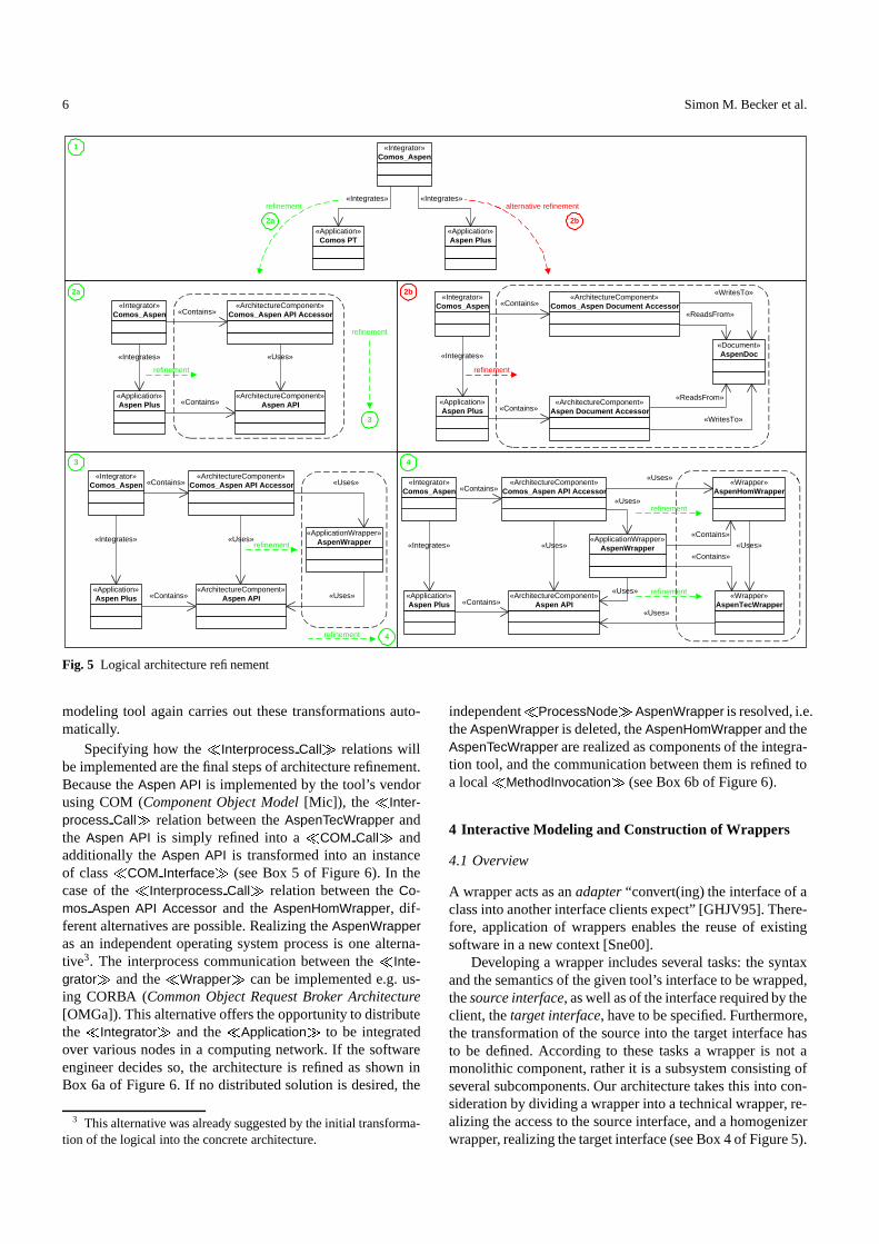
3.2.1 Logical Architecture Refinement The system descrip-tion sketched in Figure 3 serves as starting point for the ar-chitecture refinement process. The structure described thereis modeled in Box 1 of Figure 5 with the concepts providedby the logical architecture meta model (see Figure 4).
As the first refinement step the access to the applicationto be integrated by the integration tool is defined2. This can
2 For the following explanations we will focus on the right�Integrates � relation between Comos Aspen and Aspen Plus.
The left�
Integrates � relation can be refined analogously.
be done either by accessing the application via an API (ap-plication programming interface) (see Box 2a of Figure 5) or,in the case no API is offered by the application, via the docu-ments produced by the application (see Box 2b of Figure 5).The latter refinement alternative is applicable e.g. when theapplication is equipped with an XML import and export func-tion and only data integration is intended. Mixtures of alter-native 2a and 2b are possible, as well (not shown in Figure 5):if the API, for example, is a read-only interface, as in earlierreleases of Aspen Plus, read access is realized via the API,while for write access the document solution is used.
Choosing alternative 2a leads to the model shown in Box2a of Figure 5: the � Application � Aspen Plus is extendedwith an additional � ArchitectureComponent � representingthe API, that is used by the Comos Aspen API Accessor,which is an � ArchitectureComponent � of the Integrator. This
� Uses � relation between the Comos Aspen API Accessorand the Aspen API is subsequently refined in step 3 and 4:An � ApplicationWrapper � is introduced (see Box 3 of Fig-ure 5) which is subdivided into a so-called homogenizer wrap-per (AspenHomWrapper) and a technical wrapper (Aspen-TecWrapper) (see Box 4 of Figure 5). This is done for the fol-lowing reasons: The integration tool expects the tool’s datato be provided as attributed, directed, node- and edge-labeledgraphs (see Figure 13 and Figure 14). Therefore, the propri-etary data model provided by the tool’s API has to be trans-formed by the homogenizer wrapper into the graph model.In this context the technical wrapper offers the homogenizerwrapper a location- and implementation-independent accessto the tool’s API. How the homogenizer and the technicalwrapper can be further refined, will be explained in Section 4.
Please note that for the refinement steps shown in Box 2a(or alternatively in Box 2b) user interactions are necessary:it is the software engineer’s knowledge to decide how the
� Application � is accessed by the � Integrator � . After defin-ing this, the transformations shown in Box 3 and Box 4 areperformed by the architecture modeling tool automatically.When, for example, the software engineer decides later thatno homogenizer wrapper is necessary, he can delete this com-ponent manually.
3.2.2 Concrete Architecture Refinement So far we have spec-ified the logical architecture of our system. The next step is todefine the concrete architecture. Therefore, the logical struc-ture is transformed in an isomorphic, concrete one (see Box 5of Figure 6): instances of the classes Application and Inte-grator, respectively instances of subclasses, are transformedinto instances of class ProcessNode. They represent a pro-cess in the operating system sense. Instances of class Archi-tectureComponent, respectively instances of subclasses, aretransformed into instances of class ComponentImplementa-tion, respectively into instances of corresponding subclasses.While the � Contains � relations are kept, the � Uses � re-lations are as well transformed into equivalent � MethodIn-vocation � or � Interprocess Call � relations. A � Method-Invocation � represents a local communication, an � Inter-process Call � represents a distributed one. The architecture
6 Simon M. Becker et al.
refinement
refinement
«Integrator» Comos_Aspen
«Application» Aspen Plus
«Document» AspenDoc «Integrates»
«WritesTo»
«ReadsFrom»
«ReadsFrom»
«WritesTo»
«Contains»
«Contains»
refinement
1
2a 2b
3 4
«Integrator» Comos_Aspen
«Application» Aspen Plus
«Integrates»
«Contains»
«Contains»
«Uses»
«Uses»
«Uses»
«ApplicationWrapper» AspenWrapper refinement
«Wrapper» AspenHomWrapper
«Wrapper» AspenTecWrapper
«Contains»
«Contains»
«Uses»
«Integrator» Comos_Aspen
«Application» Aspen Plus
«Integrates»
«Contains»
«Contains»
«Uses»
«Uses»
«ApplicationWrapper» AspenWrapper
refinement
refinement
refinement
«Integrator» Comos_Aspen
«Application» Aspen Plus
«Integrates»
«Contains»
«Contains»
«Uses»
refinement
«Integrator» Comos_Aspen
«Application» Comos PT
«Application» Aspen Plus
«Integrates» «Integrates» alternative refinement
2a 2b
3
4
«ArchitectureComponent» Aspen API
«ArchitectureComponent» Comos_Aspen API Accessor
«ArchitectureComponent» Aspen Document Accessor
«ArchitectureComponent» Comos_Aspen Document Accessor
«ArchitectureComponent» Aspen API
«ArchitectureComponent» Comos_Aspen API Accessor «ArchitectureComponent»
Comos_Aspen API Accessor
«ArchitectureComponent» Aspen API
«Uses»
«Uses»
«Uses»
Fig. 5 Logical architecture refinement
modeling tool again carries out these transformations auto-matically.
Specifying how the � Interprocess Call � relations willbe implemented are the final steps of architecture refinement.Because the Aspen API is implemented by the tool’s vendorusing COM (Component Object Model [Mic]), the � Inter-process Call � relation between the AspenTecWrapper andthe Aspen API is simply refined into a � COM Call � andadditionally the Aspen API is transformed into an instanceof class � COM Interface � (see Box 5 of Figure 6). In thecase of the � Interprocess Call � relation between the Co-mos Aspen API Accessor and the AspenHomWrapper, dif-ferent alternatives are possible. Realizing the AspenWrapperas an independent operating system process is one alterna-tive3. The interprocess communication between the � Inte-grator � and the � Wrapper � can be implemented e.g. us-ing CORBA (Common Object Request Broker Architecture[OMGa]). This alternative offers the opportunity to distributethe � Integrator � and the � Application � to be integratedover various nodes in a computing network. If the softwareengineer decides so, the architecture is refined as shown inBox 6a of Figure 6. If no distributed solution is desired, the
3 This alternative was already suggested by the initial transforma-tion of the logical into the concrete architecture.
independent � ProcessNode � AspenWrapper is resolved, i.e.the AspenWrapper is deleted, the AspenHomWrapper and theAspenTecWrapper are realized as components of the integra-tion tool, and the communication between them is refined toa local � MethodInvocation � (see Box 6b of Figure 6).
4 Interactive Modeling and Construction of Wrappers
4.1 Overview
A wrapper acts as an adapter “convert(ing) the interface of aclass into another interface clients expect” [GHJV95]. There-fore, application of wrappers enables the reuse of existingsoftware in a new context [Sne00].
Developing a wrapper includes several tasks: the syntaxand the semantics of the given tool’s interface to be wrapped,the source interface, as well as of the interface required by theclient, the target interface, have to be specified. Furthermore,the transformation of the source into the target interface hasto be defined. According to these tasks a wrapper is not amonolithic component, rather it is a subsystem consisting ofseveral subcomponents. Our architecture takes this into con-sideration by dividing a wrapper into a technical wrapper, re-alizing the access to the source interface, and a homogenizerwrapper, realizing the target interface (see Box 4 of Figure 5).

Model-Based A-Posteriori Integration of Engineering Tools for Incremental Development Processes 7
«Contains »
«Contains »
« Interprocess_Cal l »
« Interprocess_Cal l »
« Uses »
« MethodInvocation »
« Uses »
« Uses »
«Contains »
«Contains »
«COM_Call»
«COM_Interface» Aspen API
«Wrapper» AspenHomWrapper
«Wrapper» AspenTecWrapper
«Integrator» Comos_Aspen
«Application» Aspen Plus
«ArchitectureComponent» Aspen API
«ArchitectureComponent» Comos_Aspen API Accessor
«ApplicationWrapper» AspenWrapper
«ProcessNode» Comos_Aspen
«ProcessNode» Aspen Plus
«ComponentImpl» Comos_Aspen API Accessor
«ProcessNode» AspenWrapper
«WrapperImpl» AspenHomWrapper
«WrapperImpl» AspenTecWrapper
«Refinement»
«Refinement»
«Refinement»
«Refinement»
«Refinement»
«Contains»
«Contains»
«Refinement»
realization
realization
realization
«Contains»
«Contains»
«Refinement»
refinement
refinement
refinement 6a 6b xor
5
6b 6a
« MethodInvocation »
« MethodInvocation »
« Corba_IIOP »
« MethodInvocation »
«ComponentImpl» Comos_Aspen API Accessor
«ProcessNode» AspenWrapper
«WrapperImpl» AspenHomWrapper
«WrapperImpl» AspenTecWrapper
«Contains»
«Contains»
«ProcessNode» Comos_Aspen «Contains»
«CorbaSkel» AspenHomWrapperSkel
«CorbaStub» AspenHomWrapperStub
«Contains»
«Contains»
« MethodInvocation »
« MethodInvocation »
«ComponentImpl» Comos_Aspen API Accessor
«WrapperImpl» AspenHomWrapper
«WrapperImpl» AspenTecWrapper
«ProcessNode» Comos_Aspen «Contains»
«Contains»
«Contains»
«ProcessNode» AspenWrapper
«Contains»
«Contains»
«ComponentImpl» Aspen API
Fig. 6 Concrete architecture refinement
In Subsection 4.2 we present the modeling of the techni-cal and the homogenizer wrappers’ interfaces and an exampleof our approach to interactively specify the transformation ofthe source into the target interface.
4.2 Interface modeling and interactive exploration
As described in the previous section, in our scenario AspenPlus, the tool to be integrated, contains an API implemented
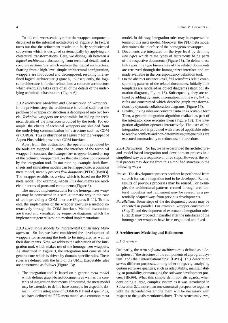
using COM. The syntax of such a COM interface is doc-umented in a standardized way through a so-called type li-brary. A type library contains a static description of the classesand their attributes and operations offered by the interface inform of signatures. By simply parsing this type library our ar-chitecture can automatically be refined as shown in Figure 74.
4 The figure shows a simplified model of the COM interface. TheCOM interface of Comos PT, for example, consists of 101 classeswith a total of 7680 methods.
8 Simon M. Becker et al.
This class diagram defines the internal data model of AspenPlus.
Figure 2 shows an example of an Aspen Plus simulationmodel. As this example illustrates, a simulation model con-sists of several components, e.g. blocks, representing chem-ical devices, streams, connecting blocks, or ports, modelingthe connection between a block and a stream. Each of thesecomponents has its own type, for example a block representsa heater or reactor.
refinement
+GetTree() : IHNode
«COM_Class» IHapp
«COM_Interface» Aspen API
«ImplementedBy»
«ImplementedBy» «ImplementedBy»
+GetElements() : IHNodeCol +GetAttributeValue(in id : Integer) : String
«COM_Class» IHNode
+GetItem(in name : String) : IHNode +GetCount() : Integer +GetItemName(in index : Integer) : String
«COM_Class» IHNodeCol
«COM_Call»
«COM_Interface» Aspen API
«WrapperImpl» AspenTecWrapper
Fig. 7 Technical wrapper refinement
According to the requirements of the integration tool, theinternal data model of Aspen Plus has to be transformed intoa graph model in conformity with the graph layer in Fig-ure 14. Therefore, an Aspen Plus simulation model compo-nent is modeled as a Node containing an attribute meta type,which is the component’s meta type, e.g. block, stream orport, and an attribute type, which is the component’s concretetype, e.g., in the case of a block, heater or reactor (see Fig-ure 8)5. The necessary operations to access instances of thismodel are offered by the export interface of the homogenizerwrapper. An example for such an operation is shown in Fig-ure 8.
«WrapperImpl» AspenHomWrapper refinement +type : String
+metatype : String
«Node» Node
+GetNodes(in type : String)
«WrapperImpl» AspenHomWrapper «Creates»
Fig. 8 Homogenizer wrapper refinement
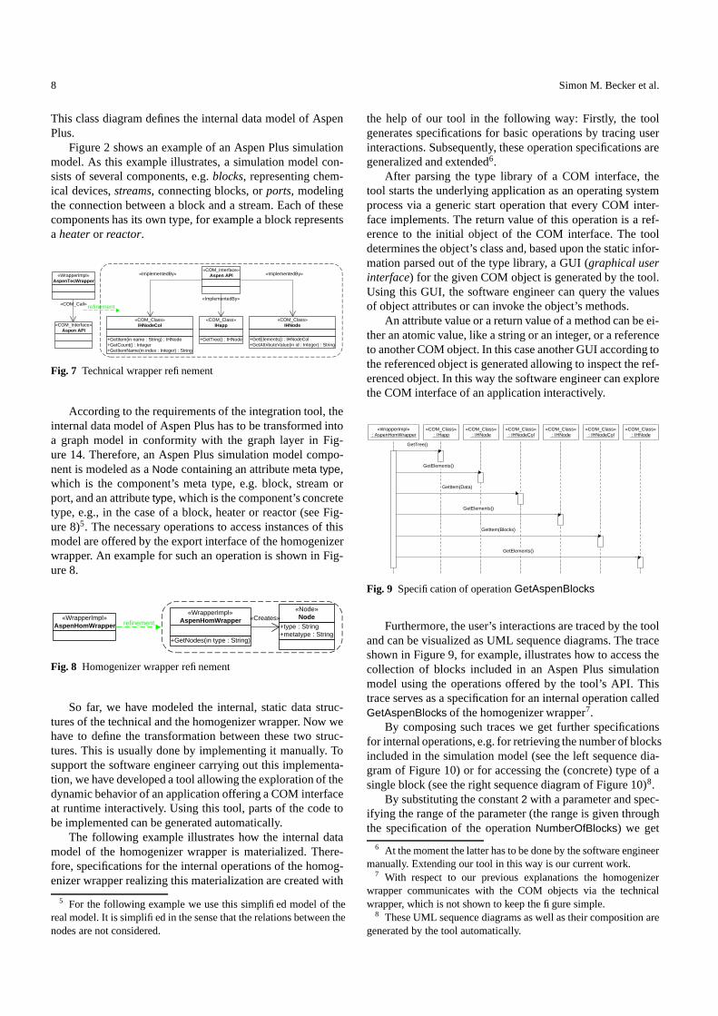
So far, we have modeled the internal, static data struc-tures of the technical and the homogenizer wrapper. Now wehave to define the transformation between these two struc-tures. This is usually done by implementing it manually. Tosupport the software engineer carrying out this implementa-tion, we have developed a tool allowing the exploration of thedynamic behavior of an application offering a COM interfaceat runtime interactively. Using this tool, parts of the code tobe implemented can be generated automatically.
The following example illustrates how the internal datamodel of the homogenizer wrapper is materialized. There-fore, specifications for the internal operations of the homog-enizer wrapper realizing this materialization are created with
5 For the following example we use this simplified model of thereal model. It is simplified in the sense that the relations between thenodes are not considered.
the help of our tool in the following way: Firstly, the toolgenerates specifications for basic operations by tracing userinteractions. Subsequently, these operation specifications aregeneralized and extended6.
After parsing the type library of a COM interface, thetool starts the underlying application as an operating systemprocess via a generic start operation that every COM inter-face implements. The return value of this operation is a ref-erence to the initial object of the COM interface. The tooldetermines the object’s class and, based upon the static infor-mation parsed out of the type library, a GUI (graphical userinterface) for the given COM object is generated by the tool.Using this GUI, the software engineer can query the valuesof object attributes or can invoke the object’s methods.
An attribute value or a return value of a method can be ei-ther an atomic value, like a string or an integer, or a referenceto another COM object. In this case another GUI according tothe referenced object is generated allowing to inspect the ref-erenced object. In this way the software engineer can explorethe COM interface of an application interactively.
«COM_Class» : IHNode
«COM_Class» : IHNodeCol
«COM_Class» : IHNode
«COM_Class» : IHNodeCol
«COM_Class» : IHNode
«COM_Class» : IHapp
«WrapperImpl» : AspenHomWrapper
GetTree()
GetElements()
GetItem(Data)
GetElements()
GetItem(Blocks)
GetElements()
Fig. 9 Specification of operation GetAspenBlocks
Furthermore, the user’s interactions are traced by the tooland can be visualized as UML sequence diagrams. The traceshown in Figure 9, for example, illustrates how to access thecollection of blocks included in an Aspen Plus simulationmodel using the operations offered by the tool’s API. Thistrace serves as a specification for an internal operation calledGetAspenBlocks of the homogenizer wrapper7.
By composing such traces we get further specificationsfor internal operations, e.g. for retrieving the number of blocksincluded in the simulation model (see the left sequence dia-gram of Figure 10) or for accessing the (concrete) type of asingle block (see the right sequence diagram of Figure 10)8.
By substituting the constant 2 with a parameter and spec-ifying the range of the parameter (the range is given throughthe specification of the operation NumberOfBlocks) we get
6 At the moment the latter has to be done by the software engineermanually. Extending our tool in this way is our current work.
7 With respect to our previous explanations the homogenizerwrapper communicates with the COM objects via the technicalwrapper, which is not shown to keep the figure simple.
8 These UML sequence diagrams as well as their composition aregenerated by the tool automatically.

Model-Based A-Posteriori Integration of Engineering Tools for Incremental Development Processes 9
«COM_Class» : IHNode
«COM_Class» : IHNodeCol
«WrapperImpl» : AspenHomWrapper
GetItemName(2)
GetItem(B3)
GetAttributeValue(6)
GetAspenBlocks ()
«WrapperImpl» : AspenHomWrapper
«COM_Class» : IHNodeCol
GetCount()
GetAspenBlocks ()
Fig. 10 Specification of operation NumberOfBlocks (left sequencediagram) and of operation GetAspenBlockType (right sequence di-agram)
«COM_Class» : IHNode
«COM_Class» : IHNodeCol
«WrapperImpl» : AspenHomWrapper
GetItemName(index)
GetItem(name)
GetAttributeValue(6)
[index < NumberOfBlocks]
GetAspenBlocks ()
«WrapperImpl» : AspenHomWrapper
«Node» : Node
«create»
*[i < NumberOfBlocks]
SetMetatype(Block)
SetType(GetAspenBlockType(i))
Fig. 11 Generalization of operation GetAspenBlockType (left se-quence diagram) and specification of operation CreateBlockNodes(right sequence diagram)
a generalized specification for accessing the (concrete) typeof any block included in an Aspen Plus simulation model(see the left sequence diagram of Figure 11). In contrast tothe traced operation GetAspenBlockType():String, the gener-alized operation has the signature GetAspenBlockType(index:-Integer):String. Based upon this operation, we can finally spec-ify an operation (see the right sequence diagram of Figure 11)that instantiates the Node classes. This operation materializesthe internal data model of the homogenizer wrapper regardingthe blocks in an Aspen Plus simulation model. Analogously,operations to handle streams and ports can be specified.
5 Executable Models for Incremental ConsistencyMangement
5.1 Overview
Whereas in Section 3 the overall architecture of an integratedsystem was discussed, in this section we describe how theconsistency management between existing tools is performedin detail. In Figure 5 a class Comos Aspen was containedin the coarse-grained architecture of the system, connectingComos PT and Aspen Plus. This class is a placeholder foran incremental integration tool, which in general supports in-cremental transformation and change propagation, browsing,and consistency check between dependent documents. In ourrunning example, the integration tool in question supportsthe consistency management between flowsheets in ComosPT and simulation models in Aspen Plus with focus on the
bidirectional, incremental transformation and change propa-gation between the two documents.
Unlike other approaches to rule-based consistency man-agement which first check for inconsistencies and then applyinconsistency resolving rules, our approach is transformation-centered: New elements and changes of existing ones in onedocument are detected and propagated to the other one.
The propagation works rule based, with the rules beingdefined in a special modeling environment called rule editor.The set of rules controlling an integration tool in general isneither complete nor unambiguous w.r.t. the documents thatare to be integrated. As a result of that integration tools donot work batch-wise but rely on two different kinds of userinteraction: First, if a rule is missing for a given situation,transformation can be performed manually. Second, if multi-ple rules are applicable and their execution is conflicting, oneof the rules has to be chosen for execution by the user.
The main idea behind the realization of our consistencymanagement approach is to keep track of the fine-grainedinter-dependencies between the contents of dependent docu-ments. The resulting inter-document relationships are explic-itly stored, which is an essential prerequisite for incrementalchange propagation between the documents. This is done inan additional document which is called integration document.
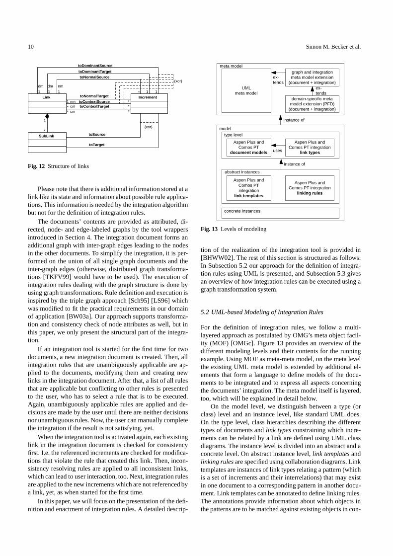
An integration document contains a set of links whichrepresent the relationships mentioned above. Each link re-lates a set of syntactic elements (increments) belonging toone document with a corresponding set belonging to anotherdocument. The integration is controlled by rules: One link iscreated by the execution of one integration rule. If a link hasto be further structured, this can be done by adding sublinksto a link. A sublink relates subsets of the increments refer-enced by its parent link and is created during the same ruleexecution as its parent.9
Figure 12 shows the structure of links in a UML class di-agram. Most constraints needed for a detailed definition areomitted, only examples are shown. An increment can havedifferent roles w.r.t. a referencing link: Increments can beowned by a link or be referenced as context increments. Whilean increment can be referenced by at most one link as ownedincrement, it can be referenced by an arbitrary number oflinks as context increments. Owned increments can be cre-ated during rule execution, whereas only existing incrementscan be referenced by new links as context increments. Con-text increments are needed when the execution of a rule de-pends on increments created by an existing link, for instanceto embed newly created edges. Owned increments can be fur-ther divided into dominant and normal increments. Dominantincrements play a special role in the execution of integrationrules (see Subsection 5.3). Each link can have at most onedominant increment in each document. A link can relate anarbitrary number of normal increments.
9 The usage of sublinks could be avoided by creating additionallinks by additional rules but this often leads to integration rules thatare hard to understand.
10 Simon M. Becker et al.
Link
SubLink
1
Increment
toDominantSource
toDominantTarget toNormalSource
toNormalTarget toContextSource toContextTarget
1 1 1 1 1
1
*
* * *
* *
1
* toSource
toTarget
{xor}
dm dm nm
nm cm cm
{xor}
Fig. 12 Structure of links
Please note that there is additional information stored at alink like its state and information about possible rule applica-tions. This information is needed by the integration algorithmbut not for the definition of integration rules.
The documents’ contents are provided as attributed, di-rected, node- and edge-labeled graphs by the tool wrappersintroduced in Section 4. The integration document forms anadditional graph with inter-graph edges leading to the nodesin the other documents. To simplify the integration, it is per-formed on the union of all single graph documents and theinter-graph edges (otherwise, distributed graph transforma-tions [TKFV99] would have to be used). The execution ofintegration rules dealing with the graph structure is done byusing graph transformations. Rule definition and execution isinspired by the triple graph approach [Sch95] [LS96] whichwas modified to fit the practical requirements in our domainof application [BW03a]. Our approach supports transforma-tion and consistency check of node attributes as well, but inthis paper, we only present the structural part of the integra-tion.
If an integration tool is started for the first time for twodocuments, a new integration document is created. Then, allintegration rules that are unambiguously applicable are ap-plied to the documents, modifying them and creating newlinks in the integration document. After that, a list of all rulesthat are applicable but conflicting to other rules is presentedto the user, who has to select a rule that is to be executed.Again, unambiguously applicable rules are applied and de-cisions are made by the user until there are neither decisionsnor unambiguous rules. Now, the user can manually completethe integration if the result is not satisfying, yet.
When the integration tool is activated again, each existinglink in the integration document is checked for consistencyfirst. I.e. the referenced increments are checked for modifica-tions that violate the rule that created this link. Then, incon-sistency resolving rules are applied to all inconsistent links,which can lead to user interaction, too. Next, integration rulesare applied to the new increments which are not referenced bya link, yet, as when started for the first time.
In this paper, we will focus on the presentation of the defi-nition and enactment of integration rules. A detailed descrip-
meta model
UML meta model
graph and integration meta model extension
(document + integration)
model type level
abstract instances
Aspen Plus and Comos PT
document models
Aspen Plus and Comos PT integration
link types
Aspen Plus and Comos PT integration
link templates
Aspen Plus and Comos PT integration
linking rules
concrete instances
instance of
instance of
ex- tends
uses
domain-specific meta model extension (PFD)
(document + integration)
ex- tends
Fig. 13 Levels of modeling
tion of the realization of the integration tool is provided in[BHWW02]. The rest of this section is structured as follows:In Subsection 5.2 our approach for the definition of integra-tion rules using UML is presented, and Subsection 5.3 givesan overview of how integration rules can be executed using agraph transformation system.
5.2 UML-based Modeling of Integration Rules
For the definition of integration rules, we follow a multi-layered approach as postulated by OMG’s meta object facil-ity (MOF) [OMGc]. Figure 13 provides an overview of thedifferent modeling levels and their contents for the runningexample. Using MOF as meta-meta model, on the meta levelthe existing UML meta model is extended by additional el-ements that form a language to define models of the docu-ments to be integrated and to express all aspects concerningthe documents’ integration. The meta model itself is layered,too, which will be explained in detail below.
On the model level, we distinguish between a type (orclass) level and an instance level, like standard UML does.On the type level, class hierarchies describing the differenttypes of documents and link types constraining which incre-ments can be related by a link are defined using UML classdiagrams. The instance level is divided into an abstract and aconcrete level. On abstract instance level, link templates andlinking rules are specified using collaboration diagrams. Linktemplates are instances of link types relating a pattern (whichis a set of increments and their interrelations) that may existin one document to a corresponding pattern in another docu-ment. Link templates can be annotated to define linking rules.The annotations provide information about which objects inthe patterns are to be matched against existing objects in con-

Model-Based A-Posteriori Integration of Engineering Tools for Incremental Development Processes 11
Class AssociationEnd Association
Node NodeEnd Edge
1
1
{r}
Link
Increment
LinkEnd
IncrementEnd
Link2Increment
1
1
{r}
{r}
UML meta model
graph meta model
generic integration meta model
Incr2Incr
1
{r} {r}
{r}
{r}
specific document and integration metamodels (here: PFD-like documents) ...
2 1
1
1
1 * * 1
1 * 1 2
1 *
1 * 1 1
Fig. 14 Extension of the UML meta model
crete documents and which have to be created, comparableto graph transformations. On the concrete instance level, ex-isting documents and integration documents can be modeled,which is not further described here. In this paper we will givea coarse overview of our modeling approach only, for a de-tailed description including more examples, the reader is re-ferred to [BW03b]10.
The modeling process to define a concrete integration toolis enacted as follows: First, if needed, specific meta modelextensions for the types of documents to be integrated haveto be created (see Subsection 5.2.1). Next, document modelsand link types have to be defined. To define the meta modelextensions and link types on type level, domain knowledgelike contained in the conceptual data model for chemical en-gineering CLiP [Bay03] is required. The document modelscan be generated with the help of the tool wrappers describedin Section 4. Now, the integration tool could be applied in thedomain of application, because link templates and integrationrules can be defined on the fly [BW03b]. Nevertheless, a ba-sic set of integration rules should be defined first to keep theadditional effort low for the user. Therefore, link templatesare to be modeled, which are consistency checked against thelink types. From each link template a set of standard linkingrules is automatically derived. All rules are stored in a rulebase and finally, are interpreted by the integration tool at run-time, using the algorithm described in Subsection 5.3.
5.2.1 Meta Model To extend the UML meta model, we makeuse of restrictive meta model extension as described in [SW01].The meta classes introduced by our meta model extensionare referred to by stereotypes on the model level. Figure 14depicts an excerpt of the meta model underlying our model-ing formalism that shows its layered structure. It is presented
10 Please note that we changed our terminology: In former publi-cations we used association instead of link type and correspondencyinstead of link template.
using MOF, but a lot of details are omitted. The top layercontains the standard UML meta model which is extendedby the next lower layer to a meta model for attributed, di-rected, node- and edge-labeled graphs. Replaces-constraints,in the figure depicted as dashed arrows marked with � r � , en-sure that the model elements of different layers cannot beused together in an unwanted fashion, e. g. resulting in anEdge connecting a Node and a UML Class.
The layer below consists of a generic integration metamodel with all elements being subclasses of the elementsfrom the graph layer. As a result of that, documents that areto be integrated and integration documents can both be re-garded as being graphs, and they can be dealt with usinggraph techniques like graph transformations. The tool wrap-pers described in Section 4 provide us with access to the doc-uments’ contents via an interface that conforms to the graphlayer of the meta model during the integration process. Theconstraints and multiplicities in Figure 12 concerning linksand their associations to increments are contained in the metamodel but not explicitly visible because they have to be de-fined as constraints on the meta model restricting the associ-ations’ cardinalities on the type level.
The meta model layers presented so far are fixed for allintegration models and tools. That is, our implementation ofthe integration framework and the modeling formalism relieson this model. If needed, on the layers below extensions forspecific types of documents can be made, which are inter-preted by all our tools.
In our running example, we deal with Comos PT flow-sheets and Aspen Plus simulation models. The overall struc-ture of both types of documents is rather similar, because bothdescribe technical systems consisting of pieces of equipmentthat are connected by via connection ports. We call thesetypes of documents PFD-like (process flow diagram like).Therefore, we defined a common meta model for PFD-likedocuments, to make the modeling of rules more user-friendly.The definition of the meta model for chemical engineering isbased on the conceptual data model CLiP [Bay03]. Here, bothdocuments to be integrated are instances of PDF-like docu-ments but in general, our approach supports the integration ofdocuments being instances of different specific meta models.The PFD-like metamodel is provided by the tool wrapperswhen importing the tools’ document models into the rule ed-itor model.
5.2.2 Type Level Detailed document models are specifiedon the type level using UML class diagrams. Here, the incre-ment types and their intra-document relations are defined. In-crement types are modeled as classes in the documents’ classhierarchies, their intra-document relations are modeled as as-sociations. Increments can be attributed but in this paper weonly deal with the structural aspects of the integration. Mostparts of the document models can be directly imported fromthe tools’ internal type systems using the tool wrappers.
Using the increment types from the detailed documentmodels, link types are defined. Because all link templateshave to be instances of link types, link types constrain the

12 Simon M. Becker et al.
«Device» PhaseSystem
«Port» ComosPort
«Port» AspenPort
«Device» MaterialStream
«Link» StreamLink
«SubLink» PortMapping
«toDominantSource» toPhaseSystem
«toDominantTarget» toMaterialStream
«toSource»
toComosPort «toPort» to
Comos Port
«toSource» toComosPort
1 1
0..2
«toTarget» toAspenPort
«toPort» toAspen
Port
* 0..1 0..1 *
0..1
1 0..1 0..1 1
1
0..2
1
0..2
«toTarget»
toAspenPort
*
0..1
*
flow sheet
simulation model
integration
Fig. 15 Link type definition
PS_IP : ComosPort
PS_OP : ComosPort
PS : PhaseSystem
SL1 : PortMapping
SL2 : PortMapping
L : StreamLink
MS_IP : AspenPort
MS_OP : AspenPort
MS : MaterialStream
:toComosPort :toAspenPort
:toComosPort :toAsp
enPort
:toPhase System
:toMaterial Stream
:toComosP
ort :toAspenPort
:toPort Mapping
:toComosPort :toAspenPort
:toComos Port
:toComos Port
:toAspen Port
:toAspen Port
flow sheet integration
simulation model
{new}
{new}
{new}
{new}
{new}
{new}
{new}
{new}
{new}
{new}
{new}
{new}
{new}
{new}
{new}
{new}
{new}
{new}
{new}
{new} :toPort Mapping
Fig. 16 Link template (without constraints printed in gray), linkingrule (with constraints)
types of increments that can be related by a link template.They also define whether a link template can be further struc-tured by sublinks and which types of increments can be re-lated by them. Figure 15 shows an example of a link type def-inition. Increments and links are modeled as classes and theirinter-relations as associations. Instances of the new link typeStreamLink can relate one stream in a Comos PT flow sheet(an increment of type PhaseSystem) with one stream in anAspen Plus simulation model (an increment of type Material-Stream). The stream increments are the dominant incrementsin both documents for the StreamLink. Additionally, up to twoports connected to the stream in each document can be ref-erenced by the link as normal increments. In most flowsheetsand simulation models, streams have one input and one out-put port, where other pieces of equipment can be connected.To map the corresponding ports on both sides of the link, upto two sub links of type StreamPortMapping can be addedto the StreamLink. The sample link type definition describedhere is rather concrete because it is specifically tailored torelate streams. Other link types can be defined that are moregeneric. For instance, in [BW03b] a link type is presented thatallows to link any pattern in a flowsheet to any other patternin a simulation model.
5.2.3 Abstract Instance Level Link templates relate corre-sponding patterns of the documents. A pattern is an abstractdescription of a situation that may occur in a concrete docu-ment. From a semantic point of view, link templates describe
that if the patterns are present in the documents they may berelated by a link. There is no information about how this linkis established or whether parts of the patterns are generated.Link templates are modeled as (static) UML collaboration di-agrams containing instances of link and sublink types that areconnected via UML links with instances of increment types.Additional constraints can be defined concerning attributesand their values.
Figure 16 depicts a link template if the constraints are nottaken into account. This link template is an instance of thelink type in Figure 15. A StreamLink relates a PhaseSystemand a Material Stream and their input and output ports. Twosublinks map the input and the output ports, which is neededfor handling connections between ports during the transfor-mation of documents as explained below. Please note thatall object names are placeholders and no concrete identifiersbelonging to existing documents. The instances’ stereotypesreferencing the meta model elements are not explicitly shownin the figure, but they can be derived from the instances ab-stractions on type level.
Link templates are purely declarative, but they can beextended to executable linking rules. Therefore, UML con-straints are added, for example � new � marks an object of thetemplate that currently is not present and has to be created.Other constraints are � not � for objects that are not present and
� delete � for objects that have to be present and are deleted.By applying these constraints to the objects of a link tem-plate, a graph transformation rule is created. The executionof linking rules is presented in the next subsection.
Comparable to the triple graph grammar approach, dif-ferent linking rules can be automatically derived from a linktemplate. A forward transformation rule finds an incrementstructure in the source document (here: the flowsheet) andcreates a corresponding structure in the target document (here:the simulation model). Both structures are then related by alink. To derive a forward transformation rule, all increments,links, and sublinks are marked with the constraint � new � , ex-cept the context increments of all documents and the ownedincrements in the flowsheet document. Association instancesthat have a least one end outside the flowsheet document aremarked with � new � , too. The linking rule in Figure 16 isthe resulting forward transformation rule. Please note that inthis example link template there are no context increments. Abackward transformation rule and other rules can be derivedsimilarly. For special needs, link templates can be manuallyextended to rules.
Another linking rule is presented in Figure 17. Please notethat the corresponding link type definition is not shown. Inflowsheets and simulation models, pieces of equipment areconnected via their ports by special increments called con-nection. The depicted rule is used to ensure that, if two sub-structures of a source document are connected and are trans-formed to a target document, the resulting substructures areconnected according to the original topology. It is a forwardtransformation rule propagating a connection in the flowsheetto the simulation model. The rules that transformed the twosubstructures already established sublinks to map the corre-
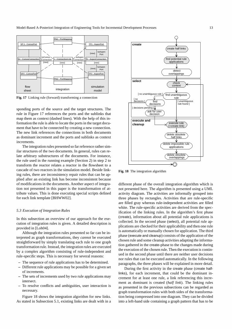
Model-Based A-Posteriori Integration of Engineering Tools for Incremental Development Processes 13
SP:1 : ComosPort
SP2 : ComosPort
S1 : ComosConnection
PM1 : PortMapping
PM2 : PortMapping
L : ConnectionLink
TP1 : AspenPort
TP2 : AspenPort
T1 : AspenConnection :toComos Connection
:toAspen Connection
:toAspen Port
:toAspen Port
flow sheet integration
simulation model
{new} {new} {new}
{new}
{new}
{new}
Fig. 17 Linking rule (forward) transforming a connection
sponding ports of the source and the target structures. Therule in Figure 17 references the ports and the sublinks thatmap them as context (dashed lines). With the help of this in-formation the rule is able to locate the ports in the target docu-ment that have to be connected by creating a new connection.The new link references the connections in both documentsas dominant increment and the ports and sublinks as contextincrements.
The integration rules presented so far reference rather sim-ilar structures of the two documents. In general, rules can re-late arbitrary substructures of the documents. For instance,the rule used in the running example (Section 2) in step 2 totransform the reactor relates a reactor in the flowsheet to acascade of two reactors in the simulation model. Beside link-ing rules, there are inconsistency repair rules that can be ap-plied after an existing link has become inconsistent becauseof modifications in the documents. Another aspect of integra-tion not presented in this paper is the transformation of at-tribute values. This is done executing special scripts definedfor each link template [BHWW02].
5.3 Execution of Integration Rules
In this subsection an overview of our approach for the exe-cution of integration rules is given. A detailed description isprovided in [Loh04].
Although the integration rules presented so far can be in-terpreted as graph transformations, they cannot be executedstraightforward by simply translating each rule to one graphtransformation rule. Instead, the integration rules are executedby a complex algorithm consisting of rule-independent andrule-specific steps. This is necessary for several reasons:
– The sequence of rule applications has to be determined.– Different rule applications may be possible for a given set
of increments.– The sets of increments used by two rule applications may
intersect.– To resolve conflicts and ambiguities, user interaction is
necessary.
Figure 18 shows the integration algorithm for new links.As stated in Subsection 5.1, existing links are dealt with in a
create
select
execute and cleanup
check context
find unambiguous rule
execute rule (=create link)
ask for user decision
delete obsolete half links
delete impossible rule applications
delete obsolete overlappings
find decisions
create half links
find potential rule applications
detect
[ unambiguous rule found ]
[ no unambiguous rule ]
[ no decisions ]
[ decisions pending ]
overlappings
Fig. 18 The integration algorithm
different phase of the overall integration algorithm which isnot presented here. The algorithm is presented using a UMLactivity diagram. The activities are informally grouped intothree phases by rectangles. Activities that are rule-specificare filled gray whereas rule-independent activities are filledwhite. The rule-specific activities are derived from the spec-ification of the linking rules. In the algorithm’s first phase(create), information about all potential rule applications iscollected. In the second phase (select), all potential rule ap-plications are checked for their applicability and then one ruleis automatically or manually chosen for application. The thirdphase (execute and cleanup) consists of the application of thechosen rule and some cleanup activities adapting the informa-tion gathered in the create-phase to the changes made duringthe execution of the chosen rule. Then the execution is contin-ued in the second phase until there are neither user decisionsnor rules that can be executed automatically. In the followingparagraphs, the three phases will be explained in more detail.
During the first activity in the create phase (create half-links), for each increment, that could be the dominant in-crement for at least one rule, a link referencing this incre-ment as dominant is created (half link). The linking rulesas presented in the previous subsections can be regarded asgraph transformation rules with both sides of the transforma-tion being compressed into one diagram. They can be dividedinto a left-hand side containing a graph pattern that has to be
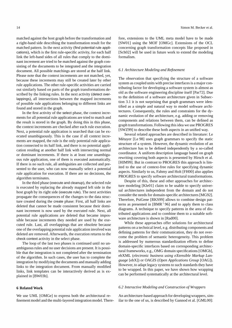
14 Simon M. Becker et al.
matched against the host graph before the transformation anda right-hand side describing the transformation result for thematched pattern. In the next activity (find potential rule appli-cations), which is the first rule-specific activity, for each halflink the left-hand sides of all rules that comply to the domi-nant increment are tried to be matched against the graph con-sisting of the documents to be integrated and the integrationdocument. All possible matchings are stored at the half link.Please note that the context increments are not matched, yet,because these increments may still be created later by otherrule applications. The other rule-specific activities are carriedout similarly based on parts of the graph transformations de-scribed by the linking rules. In the next activity (detect over-lappings), all intersections between the mapped incrementsof possible rule applications belonging to different links arefound and stored in the graph.
In the first activity of the select phase, the context incre-ments for all potential rule applications are tried to match andthe result is stored in the graph. By doing this in this phase,the context increments are checked after each rule execution.Next, a potential rule application is searched that can be ex-ecuted unambiguously. This is the case if all context incre-ments are mapped, the rule is the only potential rule applica-tion connected to its half link, and there is no potential appli-cation residing at another half link with intersecting normalor dominant increments. If there is at least one unambigu-ous rule application, one of them is executed automatically.If there is no such rule, all ambiguities are collected and pre-sented to the user, who can now manually select a potentialrule application for execution. If there are no decisions, thealgorithm terminates.
In the third phase (execute and cleanup), the selected ruleis executed by replacing the already mapped left side in thehost graph by its right side (execute rule). The next activitiespropagate the consequences of the changes to the data struc-ture created during the create phase: First, all half links aredeleted that cannot be made consistent because their domi-nant increment is now used by the executed rule. Next, allpotential rule applications are deleted that became impos-sible because increments they needed are used by the exe-cuted rule. Last, all overlappings that are obsolete becauseone of the overlapping potential rule application involved wasdeleted are removed. Afterwards, the execution returns to thecheck context activity in the select phase.
The loop of the last two phases is continued until no un-ambiguous rules and no user decisions are present. It is possi-ble that the integration is not completed after the terminationof the algorithm. In such cases, the user has to complete theintegration by modifying the documents and manually addinglinks to the integration document. From manually modifiedlinks, link templates can be interactively derived as is ex-plained in [BW03b].
6 Related Work
We use UML [OMGe] to express both the architectural re-finement model and the multi-layered integration model. There-
fore, extensions to the UML meta model have to be made[SW01] using the MOF [OMGc]. Extensions of the OCLconcerning graph transformation concepts like proposed in[Sch02] will be used in future work to extend the modelingformalism.
6.1 Architecture Modeling and Refinement
The observation that specifying the structure of a softwaresystem as coupled units with precise interfaces is a major con-tributing factor for developing a software system is almost asold as the software engineering discipline itself [Par72]. Dueto the definition of a software architecture given in Subsec-tion 3.1 it is not surprising that graph grammars were iden-tified as a simple and natural way to model software archi-tectures. Consequently, the rules and constraints for the dy-namic evolution of the architecture, e.g. adding or removingcomponents and relations between them, can be defined asgraph transformations. Following this idea we use PROGRES[SWZ99] to describe these both aspects in an unified way.
Several related approaches are described in literature: LeMetayer [Le 98] uses graph grammars to specify the staticstructure of a system. However, the dynamic evolution of anarchitecture has to be defined independently by a so-calledcoordinator. A uniform description language based on graphrewriting covering both aspects is presented by Hirsch et al.[HIM99]. But in contrast to PROGRES this approach is lim-ited to the use of context-free rules for specifying dynamicaspects. Similarly to us, Fahmy and Holt [FH00] also appliesPROGRES to specify software architectural transformations.
Despite of this, these and other approaches for architec-ture modeling [Kle01] claim to be usable to specify univer-sal architectures independent from the domain and do notconsider the needs for domain-specific architectures [MG92].Therefore, PsiGene [RKS99] allows to combine design pat-terns as presented in [BMR � 96] and to apply them to classdiagrams. A technique to specify patterns in the area of dis-tributed applications and to combine them to a suitable soft-ware architecture is shown in [Rad00].
While these approaches offer solutions for architecturalpatterns on a technical level, e.g. distributing components anddefining patterns for their communication, they do not over-come the problem of semantic heterogeneity. This problemis addressed by numerous standardization efforts to definedomain-specific interfaces based on corresponding architec-tural frameworks, e.g., OMG domain specifications [OMGb],ebXML (electronic business using eXtensible Markup Lan-guage [ebX]) or OAGIS (Open Applications Group [OAG]).However, to adapt legacy systems to such standards they haveto be wrapped. In this paper, we have shown how wrappingcan be performed systematically at the architectural level.
6.2 Interactive Modeling and Construction of Wrappers
An architecture-based approach for developing wrappers, sim-ilar to the one of us, is described by Gannod et al. [GML00]:
Model-Based A-Posteriori Integration of Engineering Tools for Incremental Development Processes 15
interfaces to command line tools are specified as architecturalcomponents by using ACME [GMW97], a generic architec-ture description language. Subsequently, based upon the spec-ification the wrapper source code for the interface is synthe-sized. In comparison with our method presented in Section 4,Gannod et al. only cover the construction of the technicalwrapper; any kind of data homogenization is not considered.
To enrich the expressiveness of a given interface to bewrapped, Jacobsen and Kramer modified CORBA IDL (in-terface definition language) [OMGa] for adding specifica-tions of semantic properties, so that a wrapper’s source codecan be extended by additional semantic checks automatically[JK98]. When wrapping tools in an a-priori manner, i.e. thesemantics of the tool’s interface is well-known, such descrip-tions are applicable for synthesizing the wrapper. Unfortu-nately, in the context of a-posteriori integration the seman-tic properties to be specified for generating the wrapper areunknown. This was one reason for developing our interfaceexploration tool.
Other attempts to discover the structure and behavior ofa software system automatically come from the field of soft-ware reengineering. Cimitile et al. [CdLdC98] describe anapproach that involves the use of data flow analysis in or-der to determine various properties of the source code to bewrapped. A necessary prerequisite for this and the most othertechniques in the area of software reengineering is the avail-ability of the source code that is to be analyzed. Again, a-posteriori integration as presented in this paper does not sat-isfy this constraint.
The solution we have chosen is an application of the “pro-gramming by example” principle [Lie01]. Several approachesfor wrapping semi-structured data sources, e.g. web pages,following this principle can be found in literature. Turquoise[MM99] is a prototype of an intelligent web browser creatingscripts to combine data from different web pages. The scriptsare demonstrated by the user’s browsing and editing actions,which Turquoise traces and generalizes into a program. Simi-lar, NoDoSE [Ade98] combines automatic analysis with userinput to specify grammars for unstructured text documents.An automation of the generalization step, necessary in everyprogramming by example approach, is presented in [Kus00].For a set of web pages single wrappers are specified manu-ally, then an automatic learning algorithm generates a gener-alized wrapper by induction.
While these “programming by example” approaches con-centrate on data integration, we are moreover interested infunction and event integration, e.g. for offering the integra-tion tool a visualized browsing functionality between inte-grated documents in the future.
6.3 Consistency Management
Our approach to consistency Management is based on differ-ent foundations in computer sciences:
The idea of relating dependent pieces of information bylinks is borrowed from hypertexts [Con87]. The Chimera sys-
tem [ATW00] is an application of hypertext concepts to soft-ware engineering. In most hypertext systems — includingChimera — links have to be established manually. Some ap-proaches to traceability, e.g. [RJ01], follow the same princi-ples.
Execution and definition of integration rules is based ongraph transformation [EEKR99,SWZ99], in particular pairgrammars [Pra71] and triple graph grammars [Sch95]. Earlywork at our department concerning integration in softwareengineering [LS96] was carried out on the basis of these tech-niques during the construction of the integrated software en-gineering environment IPSEN [Nag96]. We adapted the re-sults to our current domain of application and extended theoriginal approach: now, we are dealing with the problem of a-posteriori integration, the rule definition formalism was mod-ified to the UML-based one described in this contribution(see Section 5.2) and the rule execution algorithm was fur-ther elaborated (see Section 5.3).
Related areas of interest in computer science are (in-)consistency checking [SZ01] and model transformation. Con-sistency checkers apply rules to detect inconsistencies be-tween models which then can be resolved manually or byinconsistency repair rules. Model transformation deals withconsistent translations between heterogeneous models. Bothfields of research recently gained increasing importance be-cause of the model driven approaches for software develop-ment like the model driven architecture (MDA) [OMGd]. In[GLR � 02] the need for model transformations in the con-text of the MDA is described, some basic approaches arecompared, and requirements on transformation languages andtools are proposed. In [KS03] requirements for mapping lan-guages between different models are elaborated.
Without claiming the list to be exhaustive, here are somereferences to important projects in these areas:
XlinkIt [NCEF02,NEF03] is a project dealing with con-sistency checks. XML technology is used to check for incon-sistencies and to repair them. Because of the structure of thedocuments in our domain, we believe that UML and graphgrammars are better suited to model and execute integrationfunctionality.
The ViewPoint framework [FKG90] dates back to the earlynineties. Its main idea is to identify different perspectives(view points) of a product that is to be developed and to exam-ine their inter-relations. This framework is applied as a basisin [EHG � 02] using the formalism of distributed graph trans-formations [TKFV99] to detect and repair inconsistencies. Tothe best of our knowledge, this approach does not supportconflicting rules and user interaction.
In the context of the Fujaba project, a consistency man-agement approach was developed [WGN03]. It checks intra-model as well as inter-model consistency. Parts of the inter-model consistency check [Wag01], which can be used to trans-form models, are based on the triple graph grammar approach[Sch95] like ours, but offer restricted transformation func-tionality only, w.r.t. the detection of conflicting rules and userinteraction.
16 Simon M. Becker et al.
As part of the Kent Modeling Framework, in [AKP03] arelational approach to the definition and implementation ofmodel transformations is proposed. The definition of trans-formation rules is accomplished using UML class diagramsenriched with OCL constraints. This approach has the formalbackground of mathematical relations. It is not applicable inour domain of application because the rules are not intuitivelyunderstandable.
The QVT Partner’s proposal [ACR � 03] to the QVT RFPof the OMG [OMG02] is very similar to Kent’s approach butcomplements it with graphical definition of patterns and op-erational transformation rules. It does not support incremen-tality and user interaction.
BOTL [BM03] is a transformation language based on UMLobject diagrams. A BOTL rule consists of a left hand side dia-gram being matched in the source document and a right handside diagram being created in the target document if a lefthand side matching was found. The transformation process isneither incremental nor interactive.
In general, it can be observed that most approaches fromthe area of consistency management support an incrementalmode of operation and user interaction, whereas most modeltransformation approaches work batch-wise. In our domainof application, chemical engineering, incremental transfor-mation between models is urgently needed. But unlike MDA,in chemical engineering a complete and unambiguous defi-nition of the translation between for instance flowsheets andsimulation models is not feasible. Instead, a lot of decisionshave to be made by the user and a lot of situations have to bedealt with manually. Consistency checking approaches withrepair actions could be used for transformation, but there areproblems like conflicting transformation rules and termina-tion of the transformation process, which require further ex-tensions of the approaches. We address these problems withthe integration algorithm described in Section 5.3.
The advantage of our integration approach is that it usesstandard UML for intuitive definition of integration rules andsupports an incremental mode of operation as well as bidi-rectional transformation including conflict detection and userinteraction.
7 Conclusion
We have presented an architecture-based and model-drivenapproach to the a-posteriori integration of engineering toolsfor incremental development processes. We have realized thisapproach in the context of the CRC 476 IMPROVE, which isconcerned with models and tools for supporting design pro-cesses in chemical engineering. The case study presented inthis paper — an integration tool for consistency managementbetween flowsheets and simulation models — demonstratesthat tight integration can be achieved even in the case of a-posteriori integration of heterogeneous tools developed bydifferent vendors. Furthermore, since the tool developmentprocess is strongly architecture- and model-driven, the pro-cess can be performed at a fairly high level of abstractionwith considerably reduced effort.
An important goal of IMPROVE is to transfer researchinto industrial practice. The work reported in this paper con-stitutes a contribution towards this goal. The integration toolbetween Comos PT and Aspen Plus has been developed inclose cooperation with innotec, a software company whichdevelops and sells Comos PT. Tool development has beenperformed in close cooperation with innotec, taking the re-quirements of the industrial partner into account. Thus, theintegration tool developed in this cooperation provides a testcase for our approach to tool development. The experienceswe have gained so far are promising, but clearly further workon practical applications will have to be performed to obtainsubstantial feedback on the advantages and drawbacks of ourapproach to tool development.
Acknowledgements This work was in part funded by the CRC 476IMPROVE of the Deutsche Forschungsgemeinschaft (DFG). Fur-thermore, the authors gratefully acknowledge the fruitful coopera-tion with innotec.
References
[ACR�
03] Biju K. Appukuttan, Tony Clark, Sreedhar Reddy, Lau-rence Tratt, and R. Venkatesh. A model driven ap-proach to model transformations. In Proc. of the 2003Model Driven Architecture: Foundations and Appli-cations (MDAFA2003), CTIT Technical Report TR-CTIT-03-27. Univ. of Twente, The Netherlands, 2003.
[Ade98] Brad Adelberg. NoDoSE - a tool for semi-automa-tically extracting structured and semistructured datafrom text documents. In Proc. of the 1998 ACM SIG-MOD Intl. Conf. on Management of Data, pages 283–294, Seattle, Washington, USA, 1998. ACM.
[AKP03] David Akehurst, Stuart Kent, and Octavian Patrascoiu.A relational approach to defining and implementingtransformations between metamodels. Journal on Soft-ware and Systems Modeling, 2(Online First), 2003.
[ATW00] Kenneth M. Anderson, Richard N. Taylor, andE. James Whitehead. Chimera: Hypermedia for het-erogeneous software development environments. ACMTransactions on Information Systems, 18(3):211–245,2000.
[Bay03] Birgit Bayer. Conceptual information modeling forcomputer aided support of chemical process design.Fortschritt-Berichte VDI, Reihe 3, 787. VDI Verlag,Dusseldorf, Germany, 2003.
[BHWW02] Simon Becker, Thomas Haase, Bernhard Westfechtel,and Jens Wilhelms. Integration tools supporting coop-erative development processes in chemical engineer-ing. In Proc. of the 6th Biennial World Conf. on Inte-grated Design and Process Technology (IDPT-2002),Pasadena, California, USA, 2002. Society for Designand Process Science. 10 pp.
[BJSW02] Boris Bohlen, Dirk Jager, Ansgar Schleicher, andBernhard Westfechtel. UPGRADE: Building interac-tive tools for visual languages. In Proc. of the 6thWorld Multiconference on Systemics, Cybernetics, andInformatics (SCI 2002), volume I (Information Sys-tems Development I), pages 17–22, Orlando, Florida,USA, 2002.
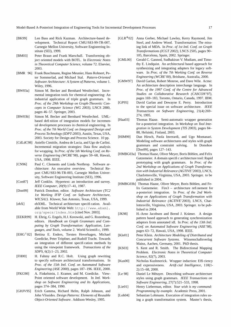
Model-Based A-Posteriori Integration of Engineering Tools for Incremental Development Processes 17
[BK99] Len Bass and Rick Kazman. Architecture-based de-velopment. Technical Report CMU/SEI-99-TR-007,Carnegie Mellon University, Software Engineering In-stitute (SEI), 1999.
[BM03] Peter Braun and Frank Marschall. Transforming ob-ject oriented models with BOTL. In Electronic Notesin Theoretical Computer Science, volume 72. Elsevier,2003.
[BMR�
96] Frank Buschmann, Regine Meunier, Hans Rohnert, Pe-ter Sommerlad, and Michael Stal. Pattern-OrientedSoftware Architecture: A System of Patterns, volume 1.Wiley, 1996.
[BW03a] Simon M. Becker and Bernhard Westfechtel. Incre-mental integration tools for chemical engineering: Anindustrial application of triple graph grammars. InProc. of the 29th Workshop on Graph-Theoretic Con-cepts in Computer Science (WG 2003), LNCS 2880,pages 46–57. Springer, 2003.
[BW03b] Simon M. Becker and Bernhard Westfechtel. UML-based definition of integration models for incremen-tal development processes in chemical engineering. InProc. of the 7th World Conf. on Integrated Design andProcess Technology (IDPT-2003), Austin, Texas, USA,2003. Society for Design and Process Science. 10 pp.
[CdLdC98] Aniello Cimitile, Andrea de Lucia, and Ugo de Carlini.Incremental migration strategies: Data flow analysisfor wrapping. In Proc. of the 5th Working Conf. on Re-verse Engineering (WCRE’98), pages 59–68, Hawaii,USA, 1998. IEEE.
[CN96] Paul C. Clements and Linda Northrop. Software ar-chitecture: An executive overview. Technical Re-port CMU/SEI-96-TR-003, Carnegie Mellon Univer-sity, Software Engineering Institute (SEI), 1996.
[Con87] Jeff Conklin. Hypertext: an introduction and survey.IEEE Computer, 20(9):17–41, 1987.
[Don99] Patrick Donohoe, editor. Software Architecture (TC21st Working IFIP Conf. on Software Architecture,WICSA1). Kluwer, San Antonio, Texas, USA, 1999.
[ebX] ebXML. Technical architecture specification. Avail-able from World Wide Web: http://www.ebxml.org/specs/index.htm [cited Nov. 2003].
[EEKR99] H. Ehrig, G. Engels, H.J. Kreowski, and G. Rozenberg,editors. Handbook on Graph Grammars and Com-puting by Graph Transformation: Application, Lan-guages, and Tools, volume 2. World Scientific, 1999.
[EHG�
02] Bettina E. Enders, Torsten Heverhagen, MichaelGoedicke, Peter Tropfner, and Rudolf Tracht. Towardsan integration of different specification methods byusing the viewpoint framework. Transactions of theSDPS, 6(2):1–23, 2002.
[FH00] H. Fahmy and R.C. Holt. Using graph rewritingto specify software architectural transformations. InProc. of the 15th Intl. Conf. on Automated SoftwareEngineering (ASE 2000), pages 187–196. IEEE, 2000.
[FKG90] A. Finkelstein, J. Kramer, and M. Goedicke. View-Point oriented software development. In Intl. Work-shop on Software Engineering and Its Applications,pages 374–384, 1990.
[GHJV95] Erich Gamma, Richard Helm, Ralph Johnson, andJohn Vlissides. Design Patterns: Elements of ReusableObject-Oriented Software. Addison-Wesley, 1995.
[GLR�
02] Anna Gerber, Michael Lawley, Kerry Raymond, JimSteel, and Andrew Wood. Transformation: The miss-ing link of MDA. In Proc. of 1st Intl. Conf. on GraphTransformations (ICGT 2002), LNCS 2505, pages 90–105, Barcelona, Spain, 2002. Springer.
[GML00] Gerald C. Gannod, Sudhakiran V. Mudiam, and Timo-thy E. Lindquist. An architectural based approach forsynthesizing and integrating adapters for legacy soft-ware. In Proc. of the 7th Working Conf. on ReverseEngineering (WCRE’00), Brisbane, Australia, 2000.
[GMW97] David Garlan, Robert Monroe, and Dave Wile. Acme:An architecture description interchange language. InProc. of the 1997 Conf. of the Centre for AdvancedStudies on Collaborative Research (CASCON’97),pages 169–183, Toronto, Ontario, Canada, 1997. IBM.
[GP95] David Garlan and Dewayne E. Perry. Introductionto the special issue on software architecture. IEEETransactions on Software Engineering, 21(4):269–274, 1995.
[Haa03] Thomas Haase. Semi-automatic wrapper generationfor a-posteriori integration. In Workshop on Tool Inte-gration in System Development (TIS 2003), pages 84–88, Helsinki, Finland, 2003.
[HIM99] Dan Hirsch, Paola Inverardi, and Ugo Montanari.Modeling software architectures and styles with graphgrammars and constraint solving. In Donohoe[Don99], pages 127–143.
[HMBG03a] Thomas Haase, Oliver Meyer, Boris Bohlen, and FelixGatzemeier. A domain specific architecture tool: Rapidprototyping with graph grammars. In Proc. of the2nd Workshop on Applications of Graph Transforma-tion with Industrial Relevance (AGTIVE’2003), LNCS,Charlottesville, Virginina, USA, 2003. Springer. to bepublished in 2004.
[HMBG03b] Thomas Haase, Oliver Meyer, Boris Bohlen, and Fe-lix Gatzemeier. Fire3 – architecture refinement fora-posteriori integration. In Proc. of the 2nd Work-shop on Applications of Graph Transformation withIndustrial Relevance (AGTIVE’2003), LNCS, Char-lottesville, Virginina, USA, 2003. Springer. to be pub-lished in 2004.
[JK98] H.-Arno Jacobsen and Bernd J. Kramer. A designpattern based approach to generating synchronizationadaptors from annotated idl. In Proc. of the 13th Intl.Conf. on Automated Software Engineering (ASE’98),pages 63–72, Hawaii, USA, 1998. IEEE.
[Kle01] Peter Klein. Architecture Modeling of Distributed andConcurrent Software Systems. WissenschaftsverlagMainz, Aachen, Germany, 2001. PhD thesis.
[KS03] S. Kent and R. Smith. The Bidirectional MappingProblem. Electronic Notes in Theoretical ComputerScience, 82(7), 2003.
[Kus00] Nicholas Kushmerick. Wrapper induction: Efficiencyand expressiveness. Artificial Intelligence, 118(1-2):15–68, 2000.
[Le 98] Daniel Le Metayer. Describing software architecturestyles using graph grammars. IEEE Transactions onSoftware Engineering, 27(7):521–533, 1998.
[Lie01] Henry Lieberman, editor. Your wish is my command:Programming by example. Academic Press, 2001.
[Loh04] Sebastian Lohmann. Execution of integration rules us-ing a graph transformation system. Master’s thesis,
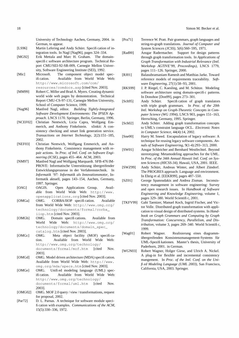
18 Simon M. Becker et al.
University of Technology Aachen, Germany, 2004. inGerman, to appear.
[LS96] Martin Lefering and Andy Schurr. Specification of in-tegration tools. In Nagl [Nag96], pages 324–334.
[MG92] Erik Mettala and Marc H. Graham. The domain-specific software architecture program. Technical Re-port CMU/SEI-92-SR-009, Carnegie Mellon Univer-sity, Software Engineering Institute (SEI), 1992.
[Mic] Microsoft. The component object model spec-ification. Available from World Wide Web:http://www.microsoft.com/com/resources/comdocs.asp [cited Nov. 2003].
[MM99] Robert C. Miller and Brad A. Myers. Creating dynamicworld wide web pages by demonstration. TechnicalReport CMU-CS-97-131, Carnegie Mellon University,School of Computer Science, 1999.
[Nag96] Manfred Nagl, editor. Building Tightly-IntegratedSoftware Development Environments: The IPSEN Ap-proach. LNCS 1170. Springer, Berlin, Germany, 1996.
[NCEF02] Christian Nentwich, Licia Capra, Wolfgang Em-merich, and Anthony Finkelstein. xlinkit: A con-sistency checking and smart link generation service.Transactions on Internet Technology, 2(2):151–185,2002.
[NEF03] Christian Nentwich, Wolfgang Emmerich, and An-thony Finkelstein. Consistency management with re-pair actions. In Proc. of Intl. Conf. on Software Engi-neering (ICSE), pages 455–464. ACM, 2003.
[NM97] Manfred Nagl and Wolfgang Marquardt. SFB-476 IM-PROVE: Informatische Unterstutzung ubergreifenderEntwicklungsprozesse in der Verfahrenstechnik. InInformatik ‘97: Informatik als Innovationsmotor, In-formatik aktuell, pages 143–154, Aachen, Germany,1997. Springer.
[OAG] OAGIS. Open Applications Group. Avail-able from World Wide Web: http://www.openapplications.org [cited Nov. 2003].
[OMGa] OMG. CORBA/IIOP specification. Availablefrom World Wide Web: http://www.omg.org/technology/documents/formal/corba_iiop.htm [cited Nov. 2003].
[OMGb] OMG. Domain specifications. Available fromWorld Wide Web: http://www.omg.org/technology/documents/domain_spec_catalog.htm [cited Nov. 2003].
[OMGc] OMG. Meta object facility (MOF) specifica-tion. Available from World Wide Web:http://www.omg.org/technology/documents/formal/mof.htm [cited Nov.2003].
[OMGd] OMG. Model driven architecture (MDA) specification.Available from World Wide Web: http://www.omg.org/mda/specs.htm [cited Nov. 2003].
[OMGe] OMG. Unified modeling language (UML) spec-ification. Available from World Wide Web:http://www.omg.org/technology/documents/formal/uml.htm [cited Nov.2003].
[OMG02] OMG. MOF 2.0 query / view / transformations, requestfor proposal, 2002.
[Par72] D. L. Parnas. A technique for software module speci-fication with examples. Communications of the ACM,15(5):330–336, 1972.
[Pra71] Terrence W. Pratt. Pair grammars, graph languages andstring-to-graph translations. Journal of Computer andSystem Sciences (JCSS), 5(6):560–595, 1971.
[Rad00] Ansgar Radermacher. Support for design patternsthrough graph transformation tools. In Applications ofGraph Transformation with Industrial Relevance (Intl.Workshop AGTIVE’99, Proceedings), LNCS 1779,pages 111–126. Springer, 2000.
[RJ01] Balasubramaniam Ramesh and Matthias Jarke. Towardreference models of requirements traceability. Soft-ware Engineering, 27(1):58–93, 2001.
[RKS99] J. P. Riegel, C. Kaesling, and M. Schutze. Modelingsoftware architecture using domain-specific patterns.In Donohoe [Don99], pages 273–301.
[Sch95] Andy Schurr. Specification of graph translatorswith triple graph grammars. In Proc. of the 20thIntl. Workshop on Graph-Theoretic Concepts in Com-puter Science (WG 1994), LNCS 903, pages 151–163,Herrsching, Germany, 1995. Springer.
[Sch02] Andy Schurr. Adding graph transformation conceptsto UML’s constraint language OCL. Electronic Notesin Computer Science, 44(4):14, 2002.
[Sne00] Harry M. Sneed. Encapsulation of legacy software: Atechnique for reusing legacy software components. An-nals of Software Engineering, 9(1-4):293–313, 2000.
[SW01] Ansgar Schleicher and Bernhard Westfechtel. Beyondstereotyping: Metamodeling approaches for the UML.In Proc. of the 34th Annual Hawaii Intl. Conf. on Sys-tem Sciences (HICSS-34), Hawaii, USA, 2001. IEEE.
[SWZ99] Andy Schurr, Andreas Winter, and Albert Zundorf.The PROGRES approach: Language and environment.In Ehrig et al. [EEKR99], pages 487–550.
[SZ01] George Spanoudakis and Andrea Zisman. Inconsis-tency management in software engineering: Surveyand open research issues. In Handbook of SoftwareEngineering and Knowledge Engineering, volume 1,pages 329–380. World Scientific, 2001.
[TKFV99] Gabi Taentzer, Manuel Koch, Ingrid Fischer, and Vic-tor Volle. Distributed graph transformation with appli-cation to visual design of distributed systems. In Hand-book on Graph Grammars and Computing by GraphTransformation: Concurrency, Parallelism, and Dis-tribution, volume 3, pages 269–340. World Scientific,1999.
[Wag01] Robert Wagner. Realisierung eines diagramm-ubergreifenden Konsistenzmanagement-Systems furUML-Spezifikationen. Master’s thesis, University ofPaderborn, 2001. in German.
[WGN03] Robert Wagner, Holger Giese, and Ulrich A. Nickel.A plug-in for flexible and incremental consistencymangement. In Proc. of the Intl. Conf. on the Uni-fied Modeling Language (UML 2003), San Francisco,California, USA, 2003. Springer.