Model B D IP an P Spei˜c ppliation prinklers For Proteting ... · Spei˜c ppliation prinklers For...
28
Models BB, SD, HIP, and AP Specific Application Sprinklers For Protecting Attics Page 1 of 28 JUNE 2017 TFP610 IMPORTANT Always refer to Technical Data Sheet TFP700 for the “INSTALLER WARNING” that provides cautions with respect to handling and instal- lation of sprinkler systems and com- ponents. Improper handling and installation can permanently damage a sprinkler system or its compo- nents and cause the sprinkler to fail to operate in a fire situation or cause it to operate prematurely. Worldwide Contacts www.tyco-fire.com General Description The TYCO Models Back to Back Dual Directional (BB), Single Directional (SD), HIP, and Attic Plus (AP) Specific Appli- cation Attic Sprinklers for Protecting Attics are fire sprinklers for combus- tible and non-combustible sloped attic spaces. While Models BB, SD, and HIP are specific application attic sprinklers, the Model AP is a specific application combustible concealed-space sprin- kler with specific application criteria for use with Models BB, SD, and HIP in attic spaces. Specific Application Attic Sprinklers provide superior fire protection in attic spaces. When compared to Stan- dard Spray Sprinklers, cost savings are achieved by eliminating branchline materials and the associated installa- tion labor. Specific Application Attic Sprinklers for Protecting Attics have undergone the most extensive fire testing ever per- formed for sloped attic spaces. They are UL Listed with their specific appli- cation guidelines for use as special sprinklers as defined by the National Fire Protection Association (NFPA). Specific Application Attic Sprinklers provide an extended coverage spacing alternative to the restricted spacing of Standard Spray Sprinklers. The Specific Application Attic Sprin- klers are the first sprinklers to be: • Listed for extended coverage in com- bustible construction • Full-scale fire tested in both wet and dry system scenarios • Full-scale tested for use in wood truss construction • Listed for specific roof slopes (Ref. Table A) The Specific Application Attic Sprin- klers provide cost control with the best level of protection by eliminat- ing the need for additional sprinklers and branchline piping. In many cases, an attic can be entirely protected with just one line of piping located below the peak of the roof using Model BB Sprin- klers. If Model SD Sprinklers or Model HIP Sprinklers are needed, one line of either at each area being covered is sufficient. For example, while using Standard Spray Sprinklers, a system in a 60 ft (18,3 m) wide attic with up to a 12:12 roof pitch designed to NFPA 13, could require seven branchlines to cover the main portion of the attic and several additional branchlines to cover the hip areas. With Specific Application Attic Sprinklers, the required coverage can be obtained with just one branchline running below the peak and one down each slope of the hip beam. This would result in approximately 90% less pipe needed for installation. This reduction in the number of branchlines saves the cost of the pipe, fittings, hangers, and associated labor by eliminating up to five branchlines. Another important aspect of the Spe- cific Application Attic Sprinkler technol- ogy, which also allows for cost savings, is the reduction in system volume. This volume reduction may result in reduc- ing the size of a dry pipe valve and air compressor, and possibly allows for quicker water delivery times, eliminat- ing the need for an accelerator.
Transcript of Model B D IP an P Spei˜c ppliation prinklers For Proteting ... · Spei˜c ppliation prinklers For...
Models BB, SD, HIP, and AP Specific Application SprinklersFor Protecting Attics
Page 1 of 28 JUNE 2017 TFP610
IMPORTANTAlways refer to Technical Data Sheet TFP700 for the “INSTALLER WARNING” that provides cautions with respect to handling and instal-lation of sprinkler systems and com-ponents. Improper handling and installation can permanently damage a sprinkler system or its compo-nents and cause the sprinkler to fail to operate in a fire situation or cause it to operate prematurely.
Worldwide Contacts www.tyco-fire.com
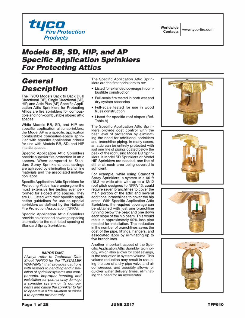
General DescriptionThe TYCO Models Back to Back Dual Directional (BB), Single Directional (SD), HIP, and Attic Plus (AP) Specific Appli-cation Attic Sprinklers for Protecting Attics are fire sprinklers for combus-tible and non-combustible sloped attic spaces.
While Models BB, SD, and HIP are specific application attic sprinklers, the Model AP is a specific application combustible concealed-space sprin-kler with specific application criteria for use with Models BB, SD, and HIP in attic spaces.
Specific Application Attic Sprinklers provide superior fire protection in attic spaces. When compared to Stan-dard Spray Sprinklers, cost savings are achieved by eliminating branchline materials and the associated installa-tion labor.
Specific Application Attic Sprinklers for Protecting Attics have undergone the most extensive fire testing ever per-formed for sloped attic spaces. They are UL Listed with their specific appli-cation guidelines for use as special sprinklers as defined by the National Fire Protection Association (NFPA).
Specific Application Attic Sprinklers provide an extended coverage spacing alternative to the restricted spacing of Standard Spray Sprinklers.
The Specific Application Attic Sprin-klers are the first sprinklers to be:
• Listed for extended coverage in com-bustible construction
• Full-scale fire tested in both wet and dry system scenarios
• Full-scale tested for use in wood truss construction
• Listed for specific roof slopes (Ref. Table A)
The Specific Application Attic Sprin-klers provide cost control with the best level of protection by eliminat-ing the need for additional sprinklers and branchline piping. In many cases, an attic can be entirely protected with just one line of piping located below the peak of the roof using Model BB Sprin-klers. If Model SD Sprinklers or Model HIP Sprinklers are needed, one line of either at each area being covered is sufficient.
For example, while using Standard Spray Sprinklers, a system in a 60 ft (18,3 m) wide attic with up to a 12:12 roof pitch designed to NFPA 13, could require seven branchlines to cover the main portion of the attic and several additional branchlines to cover the hip areas. With Specific Application Attic Sprinklers, the required coverage can be obtained with just one branchline running below the peak and one down each slope of the hip beam. This would result in approximately 90% less pipe needed for installation. This reduction in the number of branchlines saves the cost of the pipe, fittings, hangers, and associated labor by eliminating up to five branchlines.
Another important aspect of the Spe-cific Application Attic Sprinkler technol-ogy, which also allows for cost savings, is the reduction in system volume. This volume reduction may result in reduc-ing the size of a dry pipe valve and air compressor, and possibly allows for quicker water delivery times, eliminat-ing the need for an accelerator.
TFP610Page 2 of 28
Button-
De�ectorSealingAssembly -
BulbCompressionScrew
Components:
Frame--
-23
1
6
4-5
CROSSSECTION ELEVATION
2-1/4"(57,2 mm)
4 5
1-5/8"(41,3 mm)
1
3
2
6
13/16"(20,6 mm)
1-1/8"(28,6 mm)
FLOW FLOW
FRAMEARMS
1/2" (12,7 mm)NOMINALMAKE-IN
2-1/8"(54,0 mm)
WRENCHFLATS
3/4" NPT
THREADRELIEF
-
-
---
-
-
-
CompressionScrew
De�ector
DiffuserLinkAssembly
Rivet
De�ectorFrameSaddle
Lever
Components:-
--
SealingAssembly
BodyCap
1
4
23
5
76
8
109
11
ELEVATIONCROSS
SECTION
10
7
5
4
6
8
2-1/2"(63,5 mm)
21
11
2-1/4"(57,2 mm)
1-9/16"(39,7 mm)
9
7/16"(11,1 mm)NOMINALMAKE-IN
FRAMEARMS
WRENCHHEX
1-1/8"(28,6 mm)
FLOW FLOW
1/2"NPT
3
Button-
De�ectorSealingAssembly -
BulbCompressionScrew
Components:
Frame--
-23
1
6
4-5
ELEVATIONCROSS
SECTION
FRAMEARMS
54
3
7/16" (11,1 mm)NOMINALMAKE-IN
THREADRELIEF
2-1/8"(54,0 mm)
1 2
WRENCHFLATS
6
13/16"(20,6 mm)
1-1/8"(28,6 mm)
FLOW
2-1/4"(57,2 mm)
1-5/8"(41,3 mm)
FLOW
1/2" NPT
----
-
-
-
CompressionScrew
De�ector
LinkAssembly
Rivet
De�ectorFrameSaddle
Lever
Components:-
--
SealingAssembly
BodyCap
1
4
23
5
76
8
109
CROSSSECTION ELEVATION
7
4
3
6
5
10
2 1
3"(76,2 mm)
1-5/16"(33,4 mm)
FLOW
2-1/8"(54,0 mm)
FRAMEARMS
1-5/16"(33,3 mm)
9
8
WRENCHHEX
1/2"NPT
7/16" (11,1 mm)NOMINALMAKE-IN
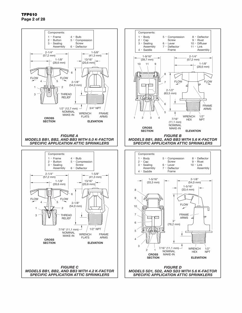
FIGURE D MODELS SD1, SD2, AND SD3 WITH 5.6 K-FACTOR
SPECIFIC APPLICATION ATTIC SPRINKLERS
FIGURE A MODELS BB1, BB2, AND BB3 WITH 8.0 K-FACTOR
SPECIFIC APPLICATION ATTIC SPRINKLERS
FIGURE C MODELS BB1, BB2, AND BB3 WITH 4.2 K-FACTOR
SPECIFIC APPLICATION ATTIC SPRINKLERS
FIGURE B MODELS BB1, BB2, AND BB3 WITH 5.6 K-FACTOR
SPECIFIC APPLICATION ATTIC SPRINKLERS

TFP610Page 3 of 28
Another cost reduction is the Listing of BLAZEMASTER CPVC for use in attic spaces to feed the wet system Specific Application Attic Sprinklers for Protect-ing Attics, as well as to feed the wet system sprinklers below the ceiling. Traditionally, BLAZEMASTER CPVC has been used on the lower floors in the joist space above a ceiling that do not require sprinklers. The cost of using CPVC on those floors can now be translated to the upper floor even if sprinklers are required in the attic.
There are four models of the Specific Application Attic Sprinklers used for protecting attics: BB, SD, HIP, and AP. The Model BB and Model SD Sprinklers have three separate versions used for different roof pitches. The pitches, as applicable, can vary from a minimum of 3:12 to a maximum of 12:12. For more information, refer to Table A.
BB Sprinkler (Back to Back Dual Directional)The Model BB Specific Application Attic Sprinkler, as seen in Figure A, B and C, throws a narrow and long pattern. The narrow spacing along the ridge serves two purposes: the response time is reduced by placing the sprinklers no farther than 6 ft (1,8 m) apart, and the spray can be concentrated in the throw direction to obtain a pattern that will cover up to 30 ft (9,1 m) in each direction when measured horizontally.
There are three different models that account for different roof slopes: BB1, BB2, and BB3. Each model is provided in one of three different orifice sizes: K=4.2, 5.6, or 8.0.
SD Sprinkler (Single Directional)The Model SD Specific Application Attic Sprinkler, as seen in Figure D, throws a narrow but long pattern like the Model BB. However, unlike the Model BB, the Model SD only throws in one direction.
Model BB Sprinklers are primarily used where shear walls or draft curtains have been installed within an attic space. Model BB Sprinklers are also used when the framing direction is parallel with the outside wall in the hip area. For more information, refer to Figure 13. In this case, the SD Model Sprinkler would be used on one side of the slope and AP Sprinklers or Standard Spray Sprinklers would be used to protect the other side.
The Model SD Sprinklers must be installed in a vertical upright orientation and not angled with the slope. Achiev-ing the vertical upright orientation may require the use of a swing joint if the SD Sprinklers are being fed from a line running along and parallel to the roof hip.
There are three different models that account for different roof slopes: SD1, SD2, and SD3.
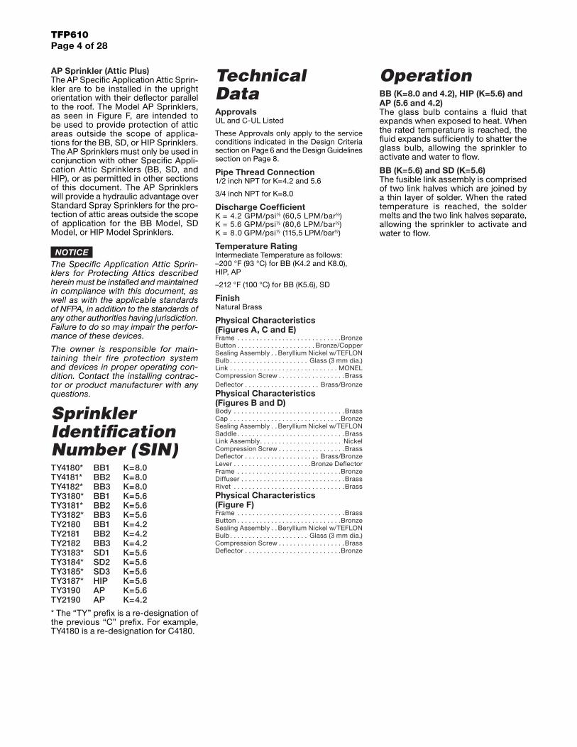
HIP SprinklerThe Model HIP Specific Application Attic Sprinkler, as seen in Figure E, covers the area of the hip in the attic. This is a slightly different concept than the BB Model or SD Model Sprinklers.
The HIP Sprinkler is located along the slope running down the hip, and throws a 90° pattern toward the outside eaves. This pattern allows the water to “corner” and control the fire.
The HIP does not throw much water directly up or down the hip, but rather it throws most of the pattern out to each side (90°) down the slope of the roof. This sprinkler is typically spaced 6 ft (1,8 m) to 3 ft (0,9 m) on center down the slope.
To use the HIP Sprinkler, the framing must be perpendicular to the outside wall (refer to Figure 12) and the maximum throw cannot exceed 28 ft (8,5 m) measured horizontally. The HIP, unlike the BB Model and SD Model, is installed with the deflector parallel with the slope. There is only one model with flows and pressures for two different spacings.
Button-
De�ectorSealingAssembly -
BulbCompressionScrew
Components:
Frame--
-23
1
6
4-5
CROSSSECTION ELEVATION
2-1/8"(54,0 mm)
FLOW6
2"(50,8 mm)
1-1/4"(31,8 mm)
2-1/8"(54,0 mm)
1-1/16"(27,0 mm)
4 5
1
FRAMEARMS
7/16" (11,1 mm)NOMINALMAKE-IN WRENCH
FLATS
1/2" NPT
THREADRELIEF
3
2
SealingAssembly
-De�ector-
SpringEjection
Bulb--
CompressionScrew
Components:
Frame--
-
Button4
2
3
1
76
5
CROSSSECTION ELEVATION
2
1
3
4
5
6
WRENCHFLATS
7/16" (11,1 mm)NOMINAL MAKE-IN
SPRINKLERFRAMEARMS
1-11/16"(42,9 mm)
2-1/4"(57,2 mm)
1/2" NPT
7
FIGURE F MODEL AP WITH 4.2 OR 5.6 K-FACTOR SPECIFIC
APPLICATION COMBUSTIBLE CONCEALED SPACE SPRINKLERS
FIGURE E MODEL HIP WITH 5.6 K-FACTOR
SPECIFIC APPLICATION ATTIC SPRINKLERS
TFP610Page 4 of 28
AP Sprinkler (Attic Plus)The AP Specific Application Attic Sprin-kler are to be installed in the upright orientation with their deflector parallel to the roof. The Model AP Sprinklers, as seen in Figure F, are intended to be used to provide protection of attic areas outside the scope of applica-tions for the BB, SD, or HIP Sprinklers. The AP Sprinklers must only be used in conjunction with other Specific Appli-cation Attic Sprinklers (BB, SD, and HIP), or as permitted in other sections of this document. The AP Sprinklers will provide a hydraulic advantage over Standard Spray Sprinklers for the pro-tection of attic areas outside the scope of application for the BB Model, SD Model, or HIP Model Sprinklers.
NOTICEThe Specific Application Attic Sprin-klers for Protecting Attics described herein must be installed and maintained in compliance with this document, as well as with the applicable standards of NFPA, in addition to the standards of any other authorities having jurisdiction. Failure to do so may impair the perfor-mance of these devices.
The owner is responsible for main-taining their fire protection system and devices in proper operating con-dition. Contact the installing contrac-tor or product manufacturer with any questions.
Sprinkler Identification Number (SIN)TY4180* BB1 K=8.0 TY4181* BB2 K=8.0 TY4182* BB3 K=8.0 TY3180* BB1 K=5.6 TY3181* BB2 K=5.6 TY3182* BB3 K=5.6 TY2180 BB1 K=4.2 TY2181 BB2 K=4.2 TY2182 BB3 K=4.2 TY3183* SD1 K=5.6 TY3184* SD2 K=5.6 TY3185* SD3 K=5.6 TY3187* HIP K=5.6 TY3190 AP K=5.6 TY2190 AP K=4.2
* The “TY” prefix is a re-designation of the previous “C” prefix. For example, TY4180 is a re-designation for C4180.
Technical DataApprovalsUL and C-UL Listed
These Approvals only apply to the service conditions indicated in the Design Criteria section on Page 6 and the Design Guidelines section on Page 8.
Pipe Thread Connection1/2 inch NPT for K=4.2 and 5.6
3/4 inch NPT for K=8.0
Discharge CoefficientK = 4.2 GPM/psi½ (60,5 LPM/bar½) K = 5.6 GPM/psi½ (80,6 LPM/bar½) K = 8.0 GPM/psi½ (115,5 LPM/bar½)
Temperature RatingIntermediate Temperature as follows: –200 °F (93 °C) for BB (K4.2 and K8.0), HIP, AP
–212 °F (100 °C) for BB (K5.6), SD
FinishNatural Brass
Physical Characteristics (Figures A, C and E)Frame . . . . . . . . . . . . . . . . . . . . . . . . . . . .BronzeButton . . . . . . . . . . . . . . . . . . . . . Bronze/CopperSealing Assembly . . Beryllium Nickel w/TEFLONBulb . . . . . . . . . . . . . . . . . . . . . Glass (3 mm dia.)Link . . . . . . . . . . . . . . . . . . . . . . . . . . . . . MONELCompression Screw . . . . . . . . . . . . . . . . . .BrassDeflector . . . . . . . . . . . . . . . . . . . . Brass/Bronze Physical Characteristics (Figures B and D)Body . . . . . . . . . . . . . . . . . . . . . . . . . . . . . .BrassCap . . . . . . . . . . . . . . . . . . . . . . . . . . . . . .BronzeSealing Assembly . . Beryllium Nickel w/TEFLONSaddle . . . . . . . . . . . . . . . . . . . . . . . . . . . . .BrassLink Assembly . . . . . . . . . . . . . . . . . . . . . . NickelCompression Screw . . . . . . . . . . . . . . . . . .BrassDeflector . . . . . . . . . . . . . . . . . . . . Brass/BronzeLever . . . . . . . . . . . . . . . . . . . . .Bronze DeflectorFrame . . . . . . . . . . . . . . . . . . . . . . . . . . . .BronzeDiffuser . . . . . . . . . . . . . . . . . . . . . . . . . . . .BrassRivet . . . . . . . . . . . . . . . . . . . . . . . . . . . . . .BrassPhysical Characteristics (Figure F)Frame . . . . . . . . . . . . . . . . . . . . . . . . . . . . .BrassButton . . . . . . . . . . . . . . . . . . . . . . . . . . . .BronzeSealing Assembly . . Beryllium Nickel w/TEFLONBulb . . . . . . . . . . . . . . . . . . . . . Glass (3 mm dia.)Compression Screw . . . . . . . . . . . . . . . . . .BrassDeflector . . . . . . . . . . . . . . . . . . . . . . . . . .Bronze
OperationBB (K=8.0 and 4.2), HIP (K=5.6) and AP (5.6 and 4.2)The glass bulb contains a fluid that expands when exposed to heat. When the rated temperature is reached, the fluid expands sufficiently to shatter the glass bulb, allowing the sprinkler to activate and water to flow.
BB (K=5.6) and SD (K=5.6)The fusible link assembly is comprised of two link halves which are joined by a thin layer of solder. When the rated temperature is reached, the solder melts and the two link halves separate, allowing the sprinkler to activate and water to flow.

TFP610Page 5 of 28
InstallationThe TYCO Specific Application Attic Sprinklers for Protecting Attics must be installed in accordance with this section.
NOTICEDo not install any bulb-type sprinkler if the bulb is cracked or there is a loss of liquid from the bulb. With the sprin-kler held horizontally, a small air bubble should be present. The diameter of the air bubble is approximately 1/16 inch (1,6 mm) for the 155°F (68°C) and 3/32 inch (2,4 mm) for the 200°F (93°C) tem-perature ratings.
A leak-tight 1/2 inch NPT sprinkler joint should be obtained by applying a min-imum-to-maximum torque of 7 to 14 ft-lb (9,5 to 19,0 Nm). Higher levels of torque can distort the sprinkler inlet with consequent leakage or impairment of the sprinkler.
To install the Specific Application Attic Sprinklers, complete the following:
Step 1. Sprinklers must be oriented correctly as follows:
• Model BB Sprinklers are to be installed in the upright vertical posi-tion with the flow arrows on the deflector pointing down the two opposing slopes.
• Model SD Sprinklers are to be installed in the upright vertical posi-tion with the flow direction arrow on the deflector pointing down the slope.
• The Model HIP Sprinklers are to be installed with the deflector at the top, the sprinkler centerline perpendicular to the ridge of the hip roof, and the flow direction arrows on the deflec-tor pointing down the two oppos-ing slopes. Unlike the Model BB and Model SD, the Model HIP is installed angled so that its deflector is paral-lel with the slope of the hip ridge line.
• The Model AP Sprinklers are to be installed in the upright position with the deflector parallel to the roof slope. There are no flow arrows on the deflector to consider; however, a good piping practice is to position all the Model AP Sprinklers so that their frame arms are in the same direction.
Step 2. With pipe thread sealant applied to the pipe threads, hand-tighten the sprinkler into the sprinkler fitting.
Note: With reference to Figure G, do not grasp the sprinkler by the deflector.
Step 3. Wrench-tighten the sprin-kler using only the wrenches shown in Figures H through M. Wrenches are only to be applied to the sprin-kler wrench flats or wrench hex, as applicable.
WRENCHFLATS
USE ENDMARKED"A" ONLY
WRENCHJAW FLANGE
ENGAGESPRINKLER
THREAD RELIEFWITH WRENCHJAW FLANGES
WRENCHFLATS
USE ENDMARKED"A" ONLY
WRENCHJAW FLANGE
ENGAGESPRINKLER
THREAD RELIEFWITH WRENCHJAW FLANGES
WRENCHHEX
ADJUSTWRENCH JAW
TO FIT WRENCHHEX
APPLYWRENCH
TO WRENCHHEX ONLY
DO NOT
WRENCHFLATS
USE ENDMARKED"A" ONLY
WRENCHJAW FLANGE
ENGAGESPRINKLER
THREAD RELIEFWITH WRENCHJAW FLANGES
WRENCHFLATS
USE ENDMARKED"A" ONLY
WRENCHJAW FLANGE
ENGAGESPRINKLER
THREAD RELIEFWITH WRENCHJAW FLANGES
FIGURE G DO NOT GRASP DEFLECTOR
FIGURE H W-TYPE 3 SPRINKLER WRENCH
FOR USE WITH BB (K=8.0) SPRINKLERS’
FIGURE K W-TYPE 20
SPRINKLER WRENCH For Use with
HIP (K=5.6) Sprinklers
FIGURE J W-TYPE 6 SPRINKLER WRENCH
For Use with BB (K=4.2) Sprinklers
FIGURE L ADJUSTABLE WRENCH
For Use with BB (K=5.6) and SD (K=5.6) Sprinklers
FIGURE M W-TYPE 6 SPRINKLER WRENCH
For Use with AP (K=4.2 and 5.6) Sprinklers
TFP610Page 6 of 28
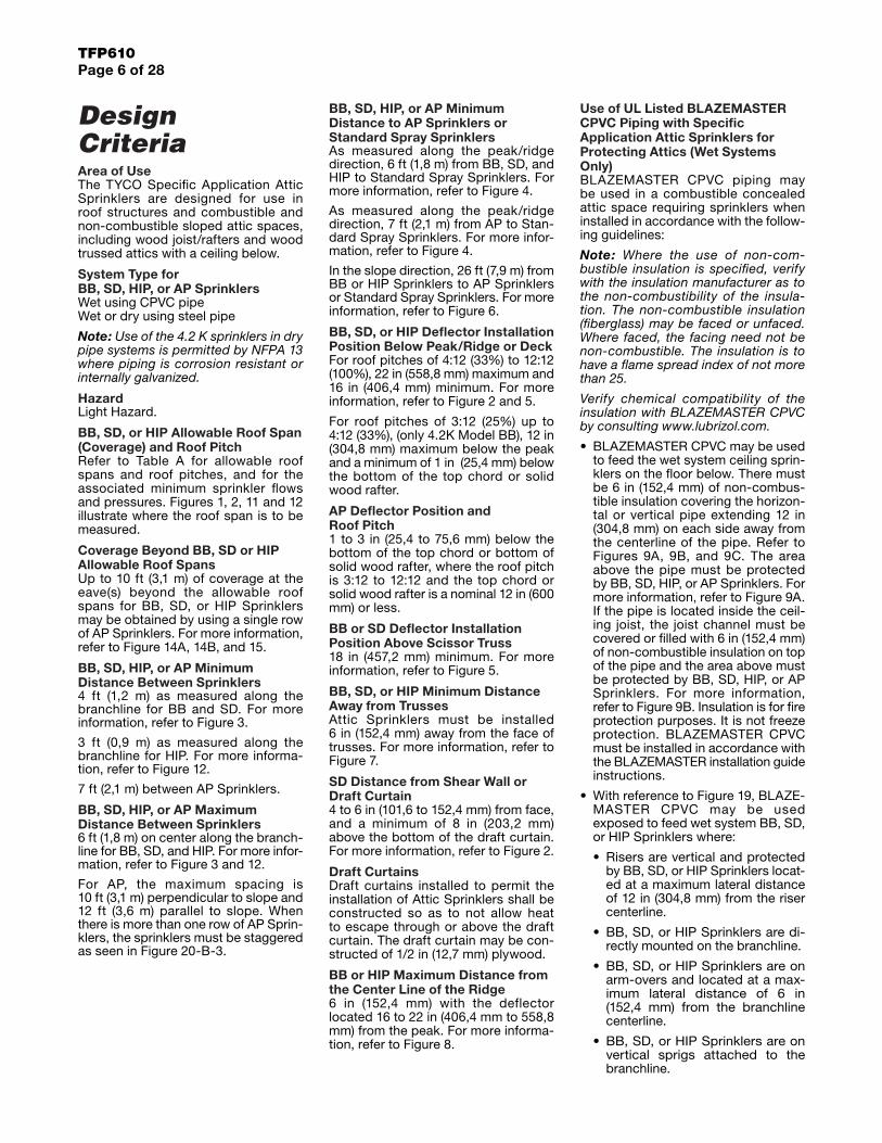
Design CriteriaArea of UseThe TYCO Specific Application Attic Sprinklers are designed for use in roof structures and combustible and non-combustible sloped attic spaces, including wood joist/rafters and wood trussed attics with a ceiling below.
System Type for BB, SD, HIP, or AP SprinklersWet using CPVC pipeWet or dry using steel pipe
Note: Use of the 4.2 K sprinklers in dry pipe systems is permitted by NFPA 13 where piping is corrosion resistant or internally galvanized.
HazardLight Hazard.
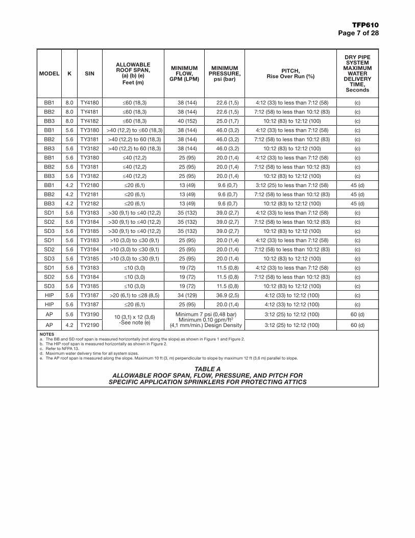
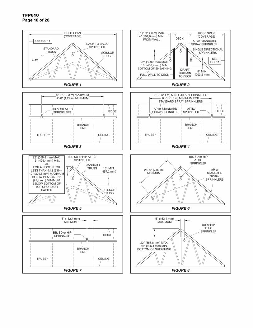
BB, SD, or HIP Allowable Roof Span (Coverage) and Roof PitchRefer to Table A for allowable roof spans and roof pitches, and for the associated minimum sprinkler flows and pressures. Figures 1, 2, 11 and 12 illustrate where the roof span is to be measured.
Coverage Beyond BB, SD or HIP Allowable Roof SpansUp to 10 ft (3,1 m) of coverage at the eave(s) beyond the allowable roof spans for BB, SD, or HIP Sprinklers may be obtained by using a single row of AP Sprinklers. For more information, refer to Figure 14A, 14B, and 15.
BB, SD, HIP, or AP Minimum Distance Between Sprinklers4 ft (1,2 m) as measured along the branchline for BB and SD. For more information, refer to Figure 3.
3 ft (0,9 m) as measured along the branchline for HIP. For more informa-tion, refer to Figure 12.
7 ft (2,1 m) between AP Sprinklers.
BB, SD, HIP, or AP Maximum Distance Between Sprinklers6 ft (1,8 m) on center along the branch-line for BB, SD, and HIP. For more infor-mation, refer to Figure 3 and 12.
For AP, the maximum spacing is 10 ft (3,1 m) perpendicular to slope and 12 ft (3,6 m) parallel to slope. When there is more than one row of AP Sprin-klers, the sprinklers must be staggered as seen in Figure 20-B-3.
BB, SD, HIP, or AP Minimum Distance to AP Sprinklers or Standard Spray SprinklersAs measured along the peak/ridge direction, 6 ft (1,8 m) from BB, SD, and HIP to Standard Spray Sprinklers. For more information, refer to Figure 4.
As measured along the peak/ridge direction, 7 ft (2,1 m) from AP to Stan-dard Spray Sprinklers. For more infor-mation, refer to Figure 4.
In the slope direction, 26 ft (7,9 m) from BB or HIP Sprinklers to AP Sprinklers or Standard Spray Sprinklers. For more information, refer to Figure 6.
BB, SD, or HIP Deflector Installation Position Below Peak/Ridge or Deck For roof pitches of 4:12 (33%) to 12:12 (100%), 22 in (558,8 mm) maximum and 16 in (406,4 mm) minimum. For more information, refer to Figure 2 and 5.
For roof pitches of 3:12 (25%) up to 4:12 (33%), (only 4.2K Model BB), 12 in (304,8 mm) maximum below the peak and a minimum of 1 in (25,4 mm) below the bottom of the top chord or solid wood rafter.
AP Deflector Position and Roof Pitch1 to 3 in (25,4 to 75,6 mm) below the bottom of the top chord or bottom of solid wood rafter, where the roof pitch is 3:12 to 12:12 and the top chord or solid wood rafter is a nominal 12 in (600 mm) or less.
BB or SD Deflector Installation Position Above Scissor Truss18 in (457,2 mm) minimum. For more information, refer to Figure 5.
BB, SD, or HIP Minimum Distance Away from TrussesAttic Sprinklers must be installed 6 in (152,4 mm) away from the face of trusses. For more information, refer to Figure 7.
SD Distance from Shear Wall or Draft Curtain4 to 6 in (101,6 to 152,4 mm) from face, and a minimum of 8 in (203,2 mm) above the bottom of the draft curtain. For more information, refer to Figure 2.
Draft CurtainsDraft curtains installed to permit the installation of Attic Sprinklers shall be constructed so as to not allow heat to escape through or above the draft curtain. The draft curtain may be con-structed of 1/2 in (12,7 mm) plywood.
BB or HIP Maximum Distance from the Center Line of the Ridge6 in (152,4 mm) with the deflector located 16 to 22 in (406,4 mm to 558,8 mm) from the peak. For more informa-tion, refer to Figure 8.
Use of UL Listed BLAZEMASTER CPVC Piping with Specific Application Attic Sprinklers for Protecting Attics (Wet Systems Only)BLAZEMASTER CPVC piping may be used in a combustible concealed attic space requiring sprinklers when installed in accordance with the follow-ing guidelines:
Note: Where the use of non-com-bustible insulation is specified, verify with the insulation manufacturer as to the non-combustibility of the insula-tion. The non-combustible insulation (fiberglass) may be faced or unfaced. Where faced, the facing need not be non-combustible. The insulation is to have a flame spread index of not more than 25.
Verify chemical compatibility of the insulation with BLAZEMASTER CPVC by consulting www.lubrizol.com.
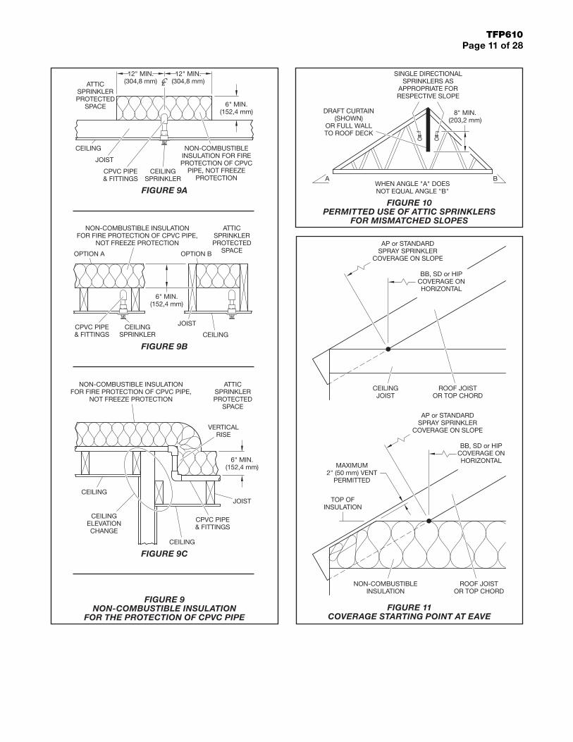
• BLAZEMASTER CPVC may be used to feed the wet system ceiling sprin-klers on the floor below. There must be 6 in (152,4 mm) of non-combus-tible insulation covering the horizon-tal or vertical pipe extending 12 in (304,8 mm) on each side away from the centerline of the pipe. Refer to Figures 9A, 9B, and 9C. The area above the pipe must be protected by BB, SD, HIP, or AP Sprinklers. For more information, refer to Figure 9A. If the pipe is located inside the ceil-ing joist, the joist channel must be covered or filled with 6 in (152,4 mm) of non-combustible insulation on top of the pipe and the area above must be protected by BB, SD, HIP, or AP Sprinklers. For more information, refer to Figure 9B. Insulation is for fire protection purposes. It is not freeze protection. BLAZEMASTER CPVC must be installed in accordance with the BLAZEMASTER installation guide instructions.
• With reference to Figure 19, BLAZE-MASTER CPVC may be used exposed to feed wet system BB, SD, or HIP Sprinklers where:
• Risers are vertical and protected by BB, SD, or HIP Sprinklers locat-ed at a maximum lateral distance of 12 in (304,8 mm) from the riser centerline.
• BB, SD, or HIP Sprinklers are di-rectly mounted on the branchline.
• BB, SD, or HIP Sprinklers are on arm-overs and located at a max-imum lateral distance of 6 in (152,4 mm) from the branchline centerline.
• BB, SD, or HIP Sprinklers are on vertical sprigs attached to the branchline.
TFP610Page 7 of 28
MODEL K SIN
ALLOWABLE ROOF SPAN,
(a) (b) (e) Feet (m)
MINIMUM FLOW,
GPM (LPM)
MINIMUM PRESSURE,
psi (bar)
PITCH, Rise Over Run (%)
DRY PIPE SYSTEM
MAXIMUM WATER
DELIVERY TIME,
Seconds
BB1 8.0 TY4180 ≤60 (18,3) 38 (144) 22.6 (1,5) 4:12 (33) to less than 7:12 (58) (c)
BB2 8.0 TY4181 ≤60 (18,3) 38 (144) 22.6 (1,5) 7:12 (58) to less than 10:12 (83) (c)
BB3 8.0 TY4182 ≤60 (18,3) 40 (152) 25.0 (1,7) 10:12 (83) to 12:12 (100) (c)
BB1 5.6 TY3180 >40 (12,2) to ≤60 (18,3) 38 (144) 46.0 (3,2) 4:12 (33) to less than 7:12 (58) (c)
BB2 5.6 TY3181 >40 (12,2) to 60 (18,3) 38 (144) 46.0 (3,2) 7:12 (58) to less than 10:12 (83) (c)
BB3 5.6 TY3182 >40 (12,2) to 60 (18,3) 38 (144) 46.0 (3,2) 10:12 (83) to 12:12 (100) (c)
BB1 5.6 TY3180 ≤40 (12,2) 25 (95) 20.0 (1,4) 4:12 (33) to less than 7:12 (58) (c)
BB2 5.6 TY3181 ≤40 (12,2) 25 (95) 20.0 (1,4) 7:12 (58) to less than 10:12 (83) (c)
BB3 5.6 TY3182 ≤40 (12,2) 25 (95) 20.0 (1,4) 10:12 (83) to 12:12 (100) (c)
BB1 4.2 TY2180 ≤20 (6,1) 13 (49) 9.6 (0,7) 3:12 (25) to less than 7:12 (58) 45 (d)
BB2 4.2 TY2181 ≤20 (6,1) 13 (49) 9.6 (0,7) 7:12 (58) to less than 10:12 (83) 45 (d)
BB3 4.2 TY2182 ≤20 (6,1) 13 (49) 9.6 (0,7) 10:12 (83) to 12:12 (100) 45 (d)
SD1 5.6 TY3183 >30 (9,1) to ≤40 (12,2) 35 (132) 39.0 (2,7) 4:12 (33) to less than 7:12 (58) (c)
SD2 5.6 TY3184 >30 (9,1) to ≤40 (12,2) 35 (132) 39.0 (2,7) 7:12 (58) to less than 10:12 (83) (c)
SD3 5.6 TY3185 >30 (9,1) to ≤40 (12,2) 35 (132) 39.0 (2,7) 10:12 (83) to 12:12 (100) (c)
SD1 5.6 TY3183 >10 (3,0) to ≤30 (9,1) 25 (95) 20.0 (1,4) 4:12 (33) to less than 7:12 (58) (c)
SD2 5.6 TY3184 >10 (3,0) to ≤30 (9,1) 25 (95) 20.0 (1,4) 7:12 (58) to less than 10:12 (83) (c)
SD3 5.6 TY3185 >10 (3,0) to ≤30 (9,1) 25 (95) 20.0 (1,4) 10:12 (83) to 12:12 (100) (c)
SD1 5.6 TY3183 ≤10 (3,0) 19 (72) 11.5 (0,8) 4:12 (33) to less than 7:12 (58) (c)
SD2 5.6 TY3184 ≤10 (3,0) 19 (72) 11.5 (0,8) 7:12 (58) to less than 10:12 (83) (c)
SD3 5.6 TY3185 ≤10 (3,0) 19 (72) 11.5 (0,8) 10:12 (83) to 12:12 (100) (c)
HIP 5.6 TY3187 >20 (6,1) to ≤28 (8,5) 34 (129) 36.9 (2,5) 4:12 (33) to 12:12 (100) (c)
HIP 5.6 TY3187 ≤20 (6,1) 25 (95) 20.0 (1,4) 4:12 (33) to 12:12 (100) (c)
AP 5.6 TY3190 10 (3,1) x 12 (3,6) -See note (e)
Minimum 7 psi (0,48 bar) Minimum 0.10 gpm/ft2
(4,1 mm/min.) Design Density
3:12 (25) to 12:12 (100) 60 (d)
AP 4.2 TY2190 3:12 (25) to 12:12 (100) 60 (d)
NOTESa. The BB and SD roof span is measured horizontally (not along the slope) as shown in Figure 1 and Figure 2.b. The HIP roof span is measured horizontally as shown in Figure 2.c. Refer to NFPA 13.d. Maximum water delivery time for all system sizes.e. The AP roof span is measured along the slope. Maximum 10 ft (3, m) perpendicular to slope by maximum 12 ft (3,6 m) parallel to slope.
TABLE A ALLOWABLE ROOF SPAN, FLOW, PRESSURE, AND PITCH FOR
SPECIFIC APPLICATION SPRINKLERS FOR PROTECTING ATTICS
TFP610Page 8 of 28
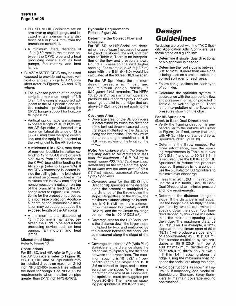
Hydraulic RequirementsRefer to Figure 20.
Determine the Correct Flow and PressureFor BB, SD, or HIP Sprinklers, deter-mine the roof span (measured horizon-tally) and the slope of the roof, and then refer to Table A. There is no interpola-tion of the flow and pressure shown. Round all cases to the next higher spacing. For example, a 45 ft (13,7 m) span with the BB1 (K=8.0) would be calculated at the 60 feet (18,3 m) span.
For the AP Sprinklers, the minimum design pressure is 7 psi, and the minimum design density is 0.10 gpm/ft² (4,1 mm/min). The NFPA 13, 20 psi (1,4 bar) minimum operating pressure for Standard Spray Sprinkler spacings parallel to the ridge that are above 8 ft (2,4 m) does not apply to the AP.
Coverage Area• Coverage area for the BB Sprinklers
is determined by twice the distance of the furthest throw measured along the slope multiplied by the distance along the branchline. The maximum distance along branchline is 6 ft (1,8 m) regardless of the length of the throw.
Note: The distance along the branch-line may have to be reduced to less than the maximum of 6 ft (1,8 m) to remain under 400 ft² (37,2 m²) maximum depending on the slope and the span. In no case can the span exceed 60 ft (18,3 m) without additional Standard Spray Sprinklers.
• Coverage area for the SD (Single Directional) Sprinklers is the distance along the branchline multiplied by the distance of the throw down the slope. Regardless of the throw, the maximum distance along the branch-line is 6 ft (1,8 m), the maximum throw measured horizontally is 40 ft (12,2 m), and the maximum coverage per sprinkler is 400 ft² (37,2 m²).
• Coverage area for the HIP Sprinklers is the distance down the larger slope multiplied by two, and multiplied by the distance between the sprinklers as measured along the slope of the hip.
• Coverage area for the AP (Attic Plus) Sprinklers is the distance along the branchline multiplied by the distance between the branchlines. The max-imum spacing is 10 ft (3,1 m) per-pendicular to the slope and 12 ft (3,6 m) parallel to slope, and as mea-sured on the slope. When there is more than one row of AP Sprinklers, the sprinklers must be staggered per Figure 20-B-3. The maximum spac-ing per sprinkler is 120 ft² (11,1 m²).
Design GuidelinesTo design a project with the TYCO Spe-cific Application Attic Sprinklers, use these steps as a guideline:
• Determine if single, dual directional or hip sprinkler is needed.
• Determine the roof slope is between 3:12 to 12:12. If more than one slope is being used on a project, select the correct sprinkler for each area.
• Follow the guidelines for each type of sprinkler.
• Calculate the sprinkler system in accordance with the appropriate flow and pressure information provided in Table A, as well as Figure 20. There is no interpolation of the flows and pressures shown on the chart.
For BB Sprinklers (Back to Back Dual Directional)• Verify the framing direction is per-
pendicular to the outside wall (refer to Figure 12). If not, cover that area with AP Sprinklers or Standard Spray Sprinklers (refer Figure 13).
• Determine the throw needed. For more information, see the spac-ing requirements in Table A. If over 20 ft (6,1 m) and up to 60 ft (18,3 m) is required, use the 8.0 K-factor, BB Sprinklers to reduce the pressure required. If pressure is not a concern, use the 5.6 K-factor, BB Sprinklers to minimize over discharge.
• If less than 20 ft (6,1 m) is required, use the 4.2 K-factor, Back to Back Dual Directional to minimize pressure and flow requirements.
• Determine the distance along the slope. If the distance is not equal, use the longer side. Multiply the lon-ger side by two to determine the spacing down the slope. Four hun-dred divided by this value will deter-mine the maximum spacing along the ridge. The maximum distance is 6 ft (1,8 m). For example, a 12:12 slope at the maximum span of 60 ft (18,3 m) will produce a slope length of approximately 42.5 ft (13,0 m). That number multiplied by two pro-duces an 85 ft (25,9 m) throw. A 400 ft² maximum divided by an 85 ft (25,9 m) throw only allows a 4 ft 8 in (1,4 m) spacing along the ridge. Using the maximum spacing, space the sprinklers along the ridge.
• Avoid obstructions as shown in Fig-ure 16. If necessary, add Model AP Sprinklers or Standard Spray Sprin-klers to maintain coverage around obstructions.
• BB, SD, or HIP Sprinklers are on arm-over or angled sprigs, and lo-cated at a maximum lateral dis-tance of 6 in (152,4 mm) from the branchline centerline.
• A minimum lateral distance of 18 in (450 mm) is maintained be-tween the CPVC pipe and a heat producing device such as heat pumps, fan motors, and heat lamps.
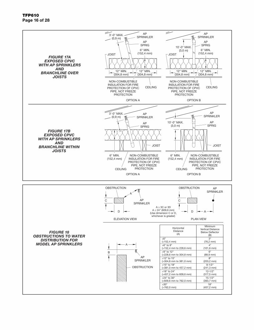
• BLAZEMASTER CPVC may be used exposed to provide wet system, ver-tical or angled, sprigs to AP Sprin-klers (refer to Figures 17A and 17B) where:
• The exposed portion of an angled sprig is a maximum length of 3 ft (0,9 m), the sprig is supported ad-jacent to the AP Sprinkler, and ver-tical restraint is provided using the CPVC hanger support for horizon-tal pipe runs.
• Vertical sprigs have a maximum exposed length of 10 ft (3,05 m), the AP Sprinkler is located at a maximum lateral distance of 12 in (3304,8 mm) from the sprig center-line, and the sprig is supported at the swing joint to the AP Sprinkler.
• A minimum 6 in (152,4 mm) deep of non-combustible insulation ex-tending 12 in (304,8 mm) on each side away from the centerline of the CPVC branchline feeding the AP sprigs (refer to Figure 17A). If the CPVC branchline is located in-side the ceiling joist, the joist chan-nel must be covered or filled with a minimum of 6 in (152,4 mm) deep of noncombustible insulation on top of the branchline feeding the AP sprigs (refer to Figure 17B). Insula-tion is for fire protection purposes. It is not freeze protection. Addition-al depth of non-combustible insu-lation may be added to reduce the exposed length of the AP sprigs.
• A minimum lateral distance of 18 in (450 mm) is maintained be-tween the CPVC pipe and a heat producing device such as heat pumps, fan motors, and heat lamps.
Mismatched SlopesRefer to Figure 10.
ObstructionsFor BB, SD, and HIP, refer to Figure 16. For AP Sprinklers, refer to Figure 18. BB, SD, HIP, and AP Sprinklers may be installed directly on maximum 2-1/2 inch NPS (DN65) branch lines without the need for sprigs. See NFPA 13 for requirements when installed on pipe greater than 2-1/2 inch NPS (DN65).
TFP610Page 9 of 28
For SD Sprinklers (Single Directional)• Determine the throw needed.
• As the 400 ft² (37,2 m²) is not a factor with the SD Sprinklers, the maximum spacing is 6 ft (1,8 m) and the mini-mum is 4 ft (1,2 m). For more infor-mation, refer to Figures 2 and 11. The reason 400 ft² is not an issue with the single directional is because, at its maximum spacing, 6 ft (1,8 m) on center / covering 40 ft (12,2 m) flat / a 12:12 slope / and the throw being 56.5 ft (17,2 m), the 400 ft² (37,2 m²) maximum would not be exceeded.
• Avoid obstructions as shown in Fig-ure 16. If necessary, add Model AP Sprinklers or Standard Spray Sprin-klers to maintain coverage around obstructions.
For HIP Sprinklers• Verify framing direction is perpendic-
ular to outside wall (refer to Figure 12). If not, cover that area with AP Sprinklers or Standard Spray Sprin-klers (refer to Figure 13).
• From the intersection of the top of the hip and the ridge, the maximum distance down the slope of the hip is 3 ft (0,9 m). Start the layout with the first sprinkler as close to that point as possible, but no further, while staying 6 in (152,4 mm) away from the face of the trusses. Remember the slope of the hip is not equal to the slope of the roof from the ridge to the out-side wall. Continue to space sprin-klers down the hip at a maximum of 6 ft (1,8 m) on center as measured along the slope of the hip. When the bottom of the hip is encountered, the last sprinkler must be within 7-1/2 ft (2,3 m) of the outside wall as mea-sured flat (plan view). If this pipe is “cut to fit”, remember to account for the different slopes of the hip and the roof, as well as distances measured along the slope verses horizontal in plan view must be accounted for.
• Avoid obstructions as shown in Fig-ure 16. If necessary, add Model AP Sprinklers or Standard Spray Sprin-klers to maintain coverage around obstructions.
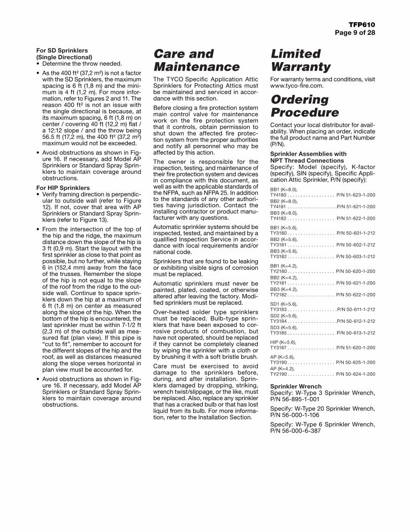
Care and MaintenanceThe TYCO Specific Application Attic Sprinklers for Protecting Attics must be maintained and serviced in accor-dance with this section.
Before closing a fire protection system main control valve for maintenance work on the fire protection system that it controls, obtain permission to shut down the affected fire protec-tion system from the proper authorities and notify all personnel who may be affected by this action.
The owner is responsible for the inspection, testing, and maintenance of their fire protection system and devices in compliance with this document, as well as with the applicable standards of the NFPA, such as NFPA 25. In addition to the standards of any other authori-ties having jurisdiction. Contact the installing contractor or product manu-facturer with any questions.
Automatic sprinkler systems should be inspected, tested, and maintained by a qualified Inspection Service in accor-dance with local requirements and/or national code.
Sprinklers that are found to be leaking or exhibiting visible signs of corrosion must be replaced.
Automatic sprinklers must never be painted, plated, coated, or otherwise altered after leaving the factory. Modi-fied sprinklers must be replaced.
Over-heated solder type sprinklers must be replaced. Bulb-type sprin-klers that have been exposed to cor-rosive products of combustion, but have not operated, should be replaced if they cannot be completely cleaned by wiping the sprinkler with a cloth or by brushing it with a soft bristle brush.
Care must be exercised to avoid damage to the sprinklers before, during, and after installation. Sprin-klers damaged by dropping, striking, wrench twist/slippage, or the like, must be replaced. Also, replace any sprinkler that has a cracked bulb or that has lost liquid from its bulb. For more informa-tion, refer to the Installation Section.
Limited WarrantyFor warranty terms and conditions, visit www.tyco-fire.com.
Ordering ProcedureContact your local distributor for avail-ability. When placing an order, indicate the full product name and Part Number (P/N).
Sprinkler Assemblies with NPT Thread ConnectionsSpecify: Model (specify), K-factor (specify), SIN (specify), Specific Appli-cation Attic Sprinkler, P/N (specify):
BB1 (K=8.0),TY4180 . . . . . . . . . . . . . . . . . . P/N 51-623-1-200BB2 (K=8.0),TY4181 . . . . . . . . . . . . . . . . . . .P/N 51-621-1-200BB3 (K=8.0),TY4182 . . . . . . . . . . . . . . . . . . P/N 51-622-1-200
BB1 (K=5.6),TY3180 . . . . . . . . . . . . . . . . . . P/N 50-601-1-212BB2 (K=5.6),TY3181 . . . . . . . . . . . . . . . . . . P/N 50-602-1-212BB3 (K=5.6),TY3182 . . . . . . . . . . . . . . . . . . P/N 50-603-1-212
BB1 (K=4.2),TY2180 . . . . . . . . . . . . . . . . . . P/N 50-620-1-200BB2 (K=4.2),TY2181 . . . . . . . . . . . . . . . . . . P/N 50-621-1-200BB3 (K=4.2),TY2182 . . . . . . . . . . . . . . . . . . P/N 50-622-1-200
SD1 (K=5.6),TY3183 . . . . . . . . . . . . . . . . . . .P/N 50-611-1-212SD2 (K=5.6),TY3184 . . . . . . . . . . . . . . . . . . .P/N 50-612-1-212SD3 (K=5.6),TY3185 . . . . . . . . . . . . . . . . . . P/N 50-613-1-212
HIP (K=5.6),TY3187 . . . . . . . . . . . . . . . . . . P/N 51-620-1-200
AP (K=5.6),TY3190 . . . . . . . . . . . . . . . . . . P/N 50-625-1-200AP (K=4.2),TY2190 . . . . . . . . . . . . . . . . . . P/N 50-624-1-200
Sprinkler WrenchSpecify: W-Type 3 Sprinkler Wrench, P/N 56-895-1-001
Specify: W-Type 20 Sprinkler Wrench, P/N 56-000-1-106
Specify: W-Type 6 Sprinkler Wrench, P/N 56-000-6-387
TFP610Page 10 of 28
ROOF SPAN(COVERAGE)
BACK TO BACKSPRINKLERSTANDARD
TRUSS SCISSORTRUSS12
4-12
SEE FIG. 11
6" (152,4 mm) MAX.4" (101,6 mm) MIN.
FROM WALL
ROOF SPAN(COVERAGE)
SINGLE DIRECTIONALSPRINKLERS
22" (558,8 mm) MAX.16" (406,4 mm) MIN.
BOTTOM OF SHEATHING8" MIN.
(203,2 mm)
DECK
DRAFTCURTAINTO DECK
AP or STANDARDSPRAY SPRINKLER
FULL WALL TO DECK
SEEFIG. 11
6'-0" (1,83 m) MAXIMUM4'-0" (1,22 m) MINIMUM
TRUSS
BB or SD ATTICSPRINKLERS
CEILING
BRANCHLINE
RIDGE
7'-0" (2,1 m) MIN. FOR AP SPRINKLERS6'-0" (1,8 m) MINIMUM FOR
STANDARD SPRAY SPRINKLERS
TRUSS CEILING
BRANCHLINE
ATTICSPRINKLER RIDGE
AP or STANDARDSPRAY SPRINKLER
22" (558,8 mm) MAX.16" (406,4 mm) MIN.
-or-FOR A ROOF PITCH
LESS THAN 4:12 (33%),12" (304,8 mm) MAXIMUM
BELOW PEAK AND 1"(25,4 mm) MINIMUMBELOW BOTTOM OF
TOP CHORD ORRAFTER
BB, SD or HIP ATTICSPRINKLER
STANDARDTRUSS
SCISSORTRUSS
18" MIN.(457,2 mm) 26'-0" (7,92 m)
MINIMUMAP or
STANDARDSPRAY
SPRINKLERS
BB, SD or HIPATTIC
SPRINKLER
6" (152,4 mm)MINIMUM
TRUSS
BB, SD or HIPSPRINKLER
CEILING
BRANCHLINE
RIDGE
6" (152,4 mm)MAXIMUM
BB or HIPATTIC
SPRINKLER
22" (558,8 mm) MAX.16" (406,4 mm) MIN.
BOTTOM OF SHEATHING
FIGURE 1 FIGURE 2
FIGURE 3 FIGURE 4
FIGURE 5 FIGURE 6
FIGURE 7 FIGURE 8
TFP610Page 11 of 28
JOIST
NON-COMBUSTIBLEINSULATION FOR FIREPROTECTION OF CPVC
PIPE, NOT FREEZEPROTECTION
12" MIN.(304,8 mm)
12" MIN.(304,8 mm)
CEILING
CEILINGSPRINKLER
6" MIN.(152,4 mm)
CPVC PIPE& FITTINGS
ATTICSPRINKLERPROTECTED
SPACE
JOISTCEILINGSPRINKLER
6" MIN.(152,4 mm)
CPVC PIPE& FITTINGS
NON-COMBUSTIBLE INSULATIONFOR FIRE PROTECTION OF CPVC PIPE,
NOT FREEZE PROTECTION
OPTION BOPTION A
CEILING
ATTICSPRINKLERPROTECTED
SPACE
6" MIN.(152,4 mm)
CPVC PIPE& FITTINGS
NON-COMBUSTIBLE INSULATIONFOR FIRE PROTECTION OF CPVC PIPE,
NOT FREEZE PROTECTION
ATTICSPRINKLERPROTECTED
SPACE
JOISTCEILING
CEILING
VERTICALRISE
CEILINGELEVATIONCHANGE
8" MIN.(203,2 mm)
DRAFT CURTAIN(SHOWN)
OR FULL WALLTO ROOF DECK
WHEN ANGLE "A" DOESNOT EQUAL ANGLE "B"
SINGLE DIRECTIONALSPRINKLERS AS
APPROPRIATE FORRESPECTIVE SLOPE
A B
CEILINGJOIST
BB, SD or HIPCOVERAGE ONHORIZONTAL
AP or STANDARDSPRAY SPRINKLER
COVERAGE ON SLOPE
AP or STANDARDSPRAY SPRINKLER
COVERAGE ON SLOPE
BB, SD or HIPCOVERAGE ONHORIZONTAL
TOP OFINSULATION
NON-COMBUSTIBLEINSULATION
ROOF JOISTOR TOP CHORD
ROOF JOISTOR TOP CHORD
MAXIMUM2" (50 mm) VENT
PERMITTED
FIGURE 9B
FIGURE 9C
FIGURE 9A
FIGURE 9 NON-COMBUSTIBLE INSULATION
FOR THE PROTECTION OF CPVC PIPE
FIGURE 10 PERMITTED USE OF ATTIC SPRINKLERS
FOR MISMATCHED SLOPES
FIGURE 11 COVERAGE STARTING POINT AT EAVE

TFP610Page 12 of 28
7'-6" (2,3 m) MAX. HORIZONTAL
HIPRIDGES
6'-0" (1,8 m) MAX.3'-0" (0,9 m) MIN.ON HIP SLOPE
SEE FIG. 113'-0" (0,9 m)
MAX. ONHIP SLOPE
OUTSIDEWALLMAXIMUM
28'-0" (8,5 m)HORIZONTAL
RIDGE LINE
RAFTERS IN HIP SLOPEAREA PERPENDICULAR
TO OUTSIDE WALLROOFSLOPE
HIPSLOPE
HIP SPRINKLERSPROTECT AREA ON
BOTH SIDES OFHIP RIDGE
SEE FIG. 11
BACKTO BACK
SPRINKLERS
HIP RIDGES
OUTSIDE WALL
6'-0" (1,8 m) MAX.6'-0" (1,8 m) MAX.
CPVC PIPE MAY BE USED IN SHADED AREA ONLYFOR CEILING PROTECTION BELOW (SEE PAGE 6)
WHERE AN AREA(SHOWN NON-SHADED)
IS PROTECTEDWITH AP SPRINKLERS,
CPVC MAY BEUSED FOR CEILING
PROTECTION BELOW(SEE PAGE 6)
HIPSLOPE
RIDGE LINE
ROOFSLOPE
BACKTO BACK
SPRINKLERS
TRUSSES IN HIP SLOPE AREAPARALLEL TO OUTSIDE WALL
STANDARD SPRAYSPRINKLERS INSTALLED
PER NFPA 13 IN HIP SLOPEAREA WHEN TRUSSES
ARE FRAMED PARALLELTO OUTSIDE WALL
SINGLEDIRECTIONALSPRINKLERS
MAXIMUM40'-0" (12,2 m)HORIZONTALROOF SPAN(COVERAGE)
3'-0" (0,9 m)MAX. ON
HIP SLOPE
3'-0" (0,9 m)MAX. ON
HIP SLOPE
CPVC PIPE MAY BE USED IN SHADED AREA ONLYFOR CEILING PROTECTION BELOW (SEE PAGE 6)
WHERE AN AREA(SHOWN NON-SHADED)
IS PROTECTEDWITH AP SPRINKLERS,
CPVC MAY BEUSED FOR CEILING
PROTECTION BELOW(SEE PAGE 6)
HIPSLOPE
RIDGE LINE
ROOFSLOPE
BACKTO BACK
SPRINKLERS
TRUSSES IN HIP SLOPE AREAPARALLEL TO OUTSIDE WALL
6'-0" (1,8 m) MAX.STANDARD SPRAYSPRINKLERS INSTALLED
PER NFPA 13 IN HIP SLOPEAREA WHEN TRUSSES
ARE FRAMED PARALLELTO OUTSIDE WALL
HIP RIDGES
OUTSIDE WALL
FIGURE 12 HIP ROOF INSTALLATION WITH RAFTERS FRAMED
PERPENDICULAR TO OUTSIDE WALL
(SHOWN WITH HIP SPRINKLERS PROTECTING HIP SLOPE AND ADJACENT
AREAS TO HIP SLOPE)
FIGURE 13A HIP ROOF INSTALLATION WITH TRUSSES FRAMED
PARALLEL TO OUTSIDE WALL (SHOWN WITH STANDARD
SPRAY OR AP SPRINKLERS IN HIP SLOPE)
FIGURE 13B HIP ROOF INSTALLATION WITH TRUSSES FRAMED
PARALLEL TO OUTSIDE WALL (SHOWN WITH STANDARD
SPRAY OR AP SPRINKLERS IN HIP SLOPE AND ADJACENT
AREAS TO HIP SLOPE)

TFP610Page 13 of 28
10'-0" MAX.(3,05 m)
APSPRINKLERCOVERAGE
APSPRINKLERS
SPACED7'-0" (1,8 m)
TO10'-0" (3,0 m)ON CENTER
6'-0" MAX.(1,83 m)
4'-0" MIN.(1,22 m)
6'-0"(1,83 m)
MAX.
BB ATTICSPRINKLER
SEE FIG. 11
BB SPAN(TABLE A)
10'-0" MAX.(3,05 m)
AP SPRINKLERCOVERAGE
SD ATTICSPRINKLER
6'-0" MAX.(1,83 m)
4'-0" MIN.(1,22 m)
6'-0"(1,83 m)
MAX.
SEE FIG. 11
APSPRINKLERS
SPACED7'-0" (1,8 m)
TO10'-0" (3,0 m)ON CENTER
SD SPAN(TABLE A)
BBSPAN
(TABLE A)
10'-0"(3,0 m)
10'-0"(3,0 m)
PERIMETERPROTECTION
AREA
HIPSPRINKLERS
BACKTO BACK
SPRINKLERS
ROOFSLOPE
10'-0"(3,0 m)
HIPSLOPE
APSPRINKLERSAT THE EAVES
HIPRIDGES
RIDGELINE
CPVC PIPE MAYBE USED IN SHADEDAREA FOR CEILING
PROTECTION BELOW(SEE PAGE 6)
7'-0" to 10'-0"(2,1 m to 3,0 m)
ON CENTER FORAP SPRINKLERS
FIGURE 14A FIGURE 14B
FIGURE 15
Attic Spaces Greater Than 60 ft (18,3m) up to 80 ft (24,4m) Wide, (refer to Figures 14 and 15).Only 8.0 K, BB Sprinklers in conjunction with AP Sprinklers or Standard Spray Sprinklers can be used to protect attics up to 80 ft (24,4 m) wide.
NOTES:
• Attics over 80 ft (24,4 m) wide must use Standard Spray Sprinklers throughout because Attic Sprinklers have not been tested in this scenario.
• For single ridge construction (refer to Figure 14A and 14B), use 8.0K, BB Sprinklers to protect the center portion. AP Sprinklers (refer to Figure 14A) or Standard Spray Sprinklers (refer to Figure 14B) are then used to protect up to 10 ft (3,1 m) of width at the eaves beyond the maximum allowable 60 ft (18,3 m) span of the 8.0K, BB Sprinklers.
• For hip roof construction (refer to Figure 15), use 8.0K, BB Sprinklers in the center portion and HIP Sprinklers can be located down the entire hip. AP Sprinklers or Standard Spray Sprinklers are then used to protect up to 10 ft (3,1 m) of width at the eaves beyond the maximum allowable 60 ft (18,3 m) span of the 8.0K, BB Sprinklers, and the maximum allowable horizontal coverage of the HIP Sprinklers.

TFP610Page 14 of 28
There can be a maximum of a 6 in. (152,4 mm) high Horizontal Obstruction as long as it is 36 in. (914,4 mm), measured vertically, below the Attic Sprinkler. If the obstruction is closer or larger, there must be a sprinkler on the other side of the obstruction. Refer to Figures 16A and 16B. This criteria does not limit the top chord of the trusses or the depth of the raf-ter, but does limit the obstructions that run across the trusses or rafters.
BB ATTICSPRINKLER
6" MAX.(152,4 mm)
36" MIN.(914,4 mm)
NOADDITIONALSPRINKLERREQUIRED
3-1/2" MIN.(88,9 mm)
AIR SPACE
BB ATTICSPRINKLERANY
DISTANCE
ADDITIONAL APOR STANDARD SPRAYSPRINKLER REQUIRED(LOCATE PER FIGURE
14A OR 14B)
GREATERTHAN 6"
(152,4 mm)
6" (152,4 mm)MINIMUM
36" (914,4 mm)MINIMUM
BB ATTICSPRINKLER
NOADDITIONALSPRINKLERREQUIRED
4'-0" (1,2 m)MAXIMUM
LESS THAN6" (152,4 mm)
36" (914,4 mm)MINIMUM
BB ATTICSPRINKLER
GREATER THAN4'-0" (1,2 m)
ADDITIONAL APOR STANDARD SPRAY
SPRINKLER(S)REQUIRED (LOCATE
PER FIGURE14A OR 14B)
40"-48" (1016,0 mm-1219,2 mm)
30"-40" (762,0 mm-1016,0 mm)
20"-30" (508,0 mm-762,0 mm)
10"-20" (254,0 mm-508,0 mm)
8"-10" (203,2 mm-254,0 mm)
4"-8" (101,4 mm-203,2 mm)
1"-4" (25,4 mm-101,6 mm)
1/2"-1" (12,7 mm-25,4 mm)
> 48" (1219,2 mm)
MaximumHorizontal
Dimension ofObstruction
All Vertical Obstructions
Dimension A
Any Distance
25'-0" (7,62 m)
20'-0" (6,10 m)
15'-0" (4,57 m)
10'-0" (3,05 m)
5'-0" (1,52 m)
24" (609,6 mm)
12" (304,8 mm)
6" (152,4 mm)
MinimumHorizontalDistance toObstruction
< 6" (152,4 mm)
Distance B
NO
YES
NO
NO
NO
NO
NO
NO
NO
YES
AdditionalSprinklerRequiredBeyond
Obstruction
DIMENSION APER TABLE
ADDITIONAL APOR STANDARD SPRAYSPRINKLER REQUIRED(LOCATE PER FIGURE
14A OR 14B)
DIMENSION BPER TABLE
If the Horizontal Obstruction is below the sprinkler, there must be 6 in. (152,4 mm) clearance over the top of the obstruction, and the obstruction must be 4 ft (1,2 m) or less in width to allow water to pass both over and under the obstruction. The clearance is measured perpendicu-lar to and from the bottom of the rafter. If there is not 6 in. must be located on the other side of the obstruc-tion. If the obstruction is greater than 4 ft (1,2 m) in width, a sprinkler must be added below the obstruction. Refer to Figures 16C and 16D, where the maximum spacing for AP Sprinklers is 12 ft (3,7 m) and Standard Spray Sprin-klers is 15 ft (4,6 m).
For Vertical Obstructions, the maximum dimension of the obstruction is its width and the horizontal distance away from the obstruction is measured horizontally.
FIGURE 16A FIGURE 16B
FIGURE 16C
FIGURE 16D
FIGURE 16E
FIGURE 16 (1 OF 2) OBSTRUCTIONS TO WATER DISTRIBUTION — BB, SD AND HIP
TFP610Page 15 of 28
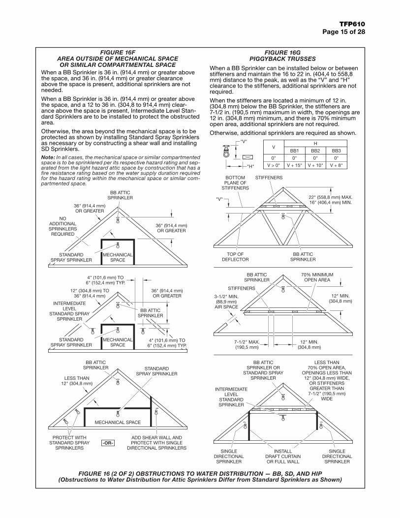
When a BB Sprinkler is 36 in. (914,4 mm) or greater above the space, and 36 in. (914,4 mm) or greater clearance above the space is present, additional sprinklers are not needed.
When a BB Sprinkler is 36 in. (914,4 mm) or greater above the space, and a 12 to 36 in. (304,8 to 914,4 mm) clear-ance above the space is present, Intermediate Level Stan-dard Sprinklers are to be installed to protect the obstructed area.
Otherwise, the area beyond the mechanical space is to be protected as shown by installing Standard Spray Sprinklers as necessary or by constructing a shear wall and installing SD Sprinklers.Note: In all cases, the mechanical space or similar compartmented space is to be sprinklered per its respective hazard rating and sep-arated from the light hazard attic space by construction that has a fire resistance rating based on the water supply duration required for the hazard rating within the mechanical space or similar com-partmented space.
When a BB Sprinkler can be installed below or between stiffeners and maintain the 16 to 22 in. (404,4 to 558,8 mm) distance to the peak, as well as the “V” and “H” clearance to the stiffeners, additional sprinklers are not required.
When the stiffeners are located a minimum of 12 in. (304,8 mm) below the BB Sprinkler, the stiffeners are 7-1/2 in. (190,5 mm) maximum in width, the openings are 12 in. (304,8 mm) minimum, and there is 70% minimum open area, additional sprinklers are not required.
Otherwise, additional sprinklers are required as shown.
FIGURE 16F AREA OUTSIDE OF MECHANICAL SPACE OR SIMILAR COMPARTMENTAL SPACE
FIGURE 16G PIGGYBACK TRUSSES
-OR-
36" (914,4 mm)OR GREATER
4" (101,6 mm) TO6" (152,4 mm) TYP.
ADD SHEAR WALL ANDPROTECT WITH SINGLE
DIRECTIONAL SPRINKLERS
MECHANICALSPACE
PROTECT WITHSTANDARD SPRAY
SPRINKLERS
MECHANICAL SPACE
LESS THAN12" (304,8 mm)
12" (304,8 mm) TO36" (914,4 mm)
BB ATTICSPRINKLER
4" (101,6 mm) TO6" (152,4 mm) TYP.
BB ATTICSPRINKLER
36" (914,4 mm)OR GREATER
NOADDITIONALSPRINKLERSREQUIRED
BB ATTICSPRINKLER
36" (914,4 mm)OR GREATER
STANDARDSPRAY SPRINKLER
STANDARDSPRAY SPRINKLER
STANDARDSPRAY SPRINKLER
MECHANICALSPACE
INTERMEDIATELEVEL
STANDARD SPRAYSPRINKLER
BB ATTICSPRINKLER
22" (558,8 mm) MAX.16" (406,4 mm) MIN.
BB ATTICSPRINKLER
70% MINIMUMOPEN AREA
7-1/2" MAX.(190,5 mm)
12" MIN.(304,8 mm)
LESS THAN70% OPEN AREA,
OPENINGS LESS THAN12" (304,8 mm) WIDE,
OR STIFFENERSGREATER THAN
7-1/2" (190,5 mm)WIDE
SINGLEDIRECTIONALSPRINKLER
INSTALLDRAFT CURTAINOR FULL WALL
INTERMEDIATELEVEL
STANDARDSPRINKLER
SINGLEDIRECTIONALSPRINKLER
BB ATTICSPRINKLER OR
STANDARD SPRAYSPRINKLER
STIFFENERS
STIFFENERS
12" MIN.(304,8 mm)
3-1/2" MIN.(88,9 mm)
AIR SPACE
"V"
BOTTOMPLANE OF
STIFFENERS
TOP OFDEFLECTOR
"V"
"H"
BB1
0"
V + 15"
0"
H
BB2
V + 10"
0"
BB3
V + 8"V > 0"
0"
V
FIGURE 16 (2 OF 2) OBSTRUCTIONS TO WATER DISTRIBUTION — BB, SD, AND HIP(Obstructions to Water Distribution for Attic Sprinklers Differ from Standard Sprinklers as Shown)
TFP610Page 16 of 28
NON-COMBUSTIBLEINSULATION FOR FIREPROTECTION OF CPVC
PIPE, NOT FREEZEPROTECTION
NON-COMBUSTIBLEINSULATION FOR FIREPROTECTION OF CPVC
PIPE, NOT FREEZEPROTECTION
12" MIN.(304,8 mm)
APSPRIG
APSPRINKLER
12" MIN.(304,8 mm)
OPTION A
6" MIN.(152,4 mm)
APSPRIG
APSPRINKLER
6" MIN.(152,4 mm)
CEILING
JOIST
3'-0" MAX.(0,9 m)
JOIST
12" MIN.(304,8 mm)
OPTION B
12" MIN.(304,8 mm)
10'-0" MAX.(3,0 m)
CEILING
OPTION B
CEILING
JOIST
OPTION A
CEILING
JOIST
NON-COMBUSTIBLEINSULATION FOR FIREPROTECTION OF CPVC
PIPE, NOT FREEZEPROTECTION
NON-COMBUSTIBLEINSULATION FOR FIREPROTECTION OF CPVC
PIPE, NOT FREEZEPROTECTION
APSPRIG
APSPRINKLER
6" MIN.(152,4 mm)
APSPRIG
APSPRINKLER
6" MIN.(152,4 mm)
3'-0" MAX.(0,9 m)
10'-0" MAX.(3,0 m)
HorizontalDistance
(A)
MinimumVertical DistanceBelow De�ector
(B)≤6"(≤152,4 mm)
3"(76,2 mm)
>6" to 9"(>152,4 mm to 228,6 mm)
4"(101,6 mm)
>9" to 12"(>228,6 mm to 304,8 mm)
6"(88,9 mm)
>12" to 15"(>304,8 mm to 381,0 mm)
8"(203,2 mm)
>15" to 18"(>381,0 mm to 457,2 mm)
9-1/2"(241,3 mm)
>18" to 24"(>457,2 mm to 609,6 mm)
12-1/2"(317,5 mm)
>24" to 30"(>609,6 mm to 762,0 mm)
15-1/2"(393,7 mm)
>30"(>762,0 mm)
18"(457,2 mm)
A ≥ 3C or 3DA ≤ 24" (609,6 mm)
(Use dimension C or D,whichever is greater)
APSPRINKLER
C
D
A
OBSTRUCTION
A
APSPRINKLER
APSPRINKLER
A
B
OBSTRUCTION
ELEVATION VIEW PLAN VIEW
C
D
OBSTRUCTION
FIGURE 17A EXPOSED CPVC
WITH AP SPRINKLERS AND
BRANCHLINE OVER JOISTS
FIGURE 17B EXPOSED CPVC
WITH AP SPRINKLERS AND
BRANCHLINE WITHIN JOISTS
FIGURE 18 OBSTRUCTIONS TO WATER
DISTRIBUTION FOR MODEL AP SPRINKLERS

TFP610Page 17 of 28
HYDRAULIC CALCULATIONS
Attic sprinklers must be calculated in conformance with these guidelines. In all cases, the design area shall include the most hydraulically demanding sprinklers. More than one set of calculations may be required to prove different situations.
For individual areas requiring more than four AP Sprinklers, the maximum area of attic protected by AP Sprinklers is limited to 3000 ft2 (279 m2) in any single area. Areas must be separated by a minimum of 15 ft (4,6 m) by an area protected by BB, SD,or HIP Sprinklers, in order to be considered separate areas.
The hydraulic calculations have been divided into three parts as follows:
• FIGURE 20-A: “Attics Protected Entirely By BB, SD, and HIP Attic Sprinklers”.
20-A-1 (Page 18) BB Sprinklers20-A-2 (Page 18) BB and HIP Sprinklers20-A-3 (Page 19) BB and SD Sprinklers20-A-4 (Page 19) SD Sprinklers20-A-5 (Page 19) SD and HIP Sprinklers20-A-6 (Page 19) HIP Sprinklers
• FIGURE 20-B: “Attics Protected With A Mixture Of BB. SD, and HIP Attic Sprinklers And AP Sprinklers”.
20-B-1 (Page 20) SD Sprinklers and AP Sprinklers At The Ridge20-B-2 (Page 20) BB Sprinklers and AP Sprinklers At The Eaves or Beyond An Obstruction20-B-3 (Page 21) BB Sprinklers and AP Sprinklers At The Hip20-B-4 (Page 21) BB Sprinklers, SD Sprinklers, HIP Sprinklers, and AP Sprinklers At The Hip20-B-5 (Page 22) BB, SD, or HIP Sprinklers and AP Sprinklers in a Dormer, at a Cross, or at an Ell20-B-6 (Page 22) BB,SD, or HIP Sprinklers and AP Sprinklers Separated By Compartmentalization
• FIGURE 20-C: “Attics Protected With A Mixture Of BB. SD, and HIP Attic Sprinklers And Standard Spray Sprinklers”.
20-C-1 (Page 23) SD Sprinklers and Standard Spray Sprinklers At The Ridge20-C-2 (Page 23) BB Sprinklers and Standard Spray Sprinklers At The Eaves or Beyond An Obstruction20-C-3 (Page 24) BB Sprinklers and Standard Spray Sprinklers At The Hip20-C-4 (Page 25) BB Sprinklers, SD Sprinklers, HIP Sprinklers, and Standard Spray Sprinklers At The Hip20-C-5 (Page 26) BB, SD, or HIP Sprinklers and Standard Spray Sprinklers in a Dormer, at a Cross, or at an Ell20-C-6 (Page 26) BB, SD, or HIP Sprinklers and Standard Sprinklers Separated By Compartmentalization
B
A A
B
A
VERTICAL RISER VERTICAL RISER
BRANCHLINE
VERTICAL SPRIG
ARMOVER SPRIG
ANGLE SPRIG
ARMOVER
DIRECT MOUNT
BRANCHLINE
A = 6" (150 mm) MAX.B = 12" (300 mm) MAX.
MODEL BBBACK TO BACK
MODEL SDSINGLE DIRECTIONAL MODEL HIP
MODEL APOR STANDARD
SPRAY
FIGURE 19
FIGURE 20 HYDRAULIC CALCULATIONS

TFP610Page 18 of 28
RIDGE
DRY SYSTEM SHOWN
RIDGE
DRY SYSTEM SHOWN
RIDGE
DRY SYSTEM SHOWN
HIP
HIP
VALL
EY
FIGURE 20-A-1. BB SPRINKLERS
• Wet Systems: Calculate the most demanding five sprinklers.
• Dry Systems: Calculate the most demanding seven sprinklers. See the adjacent figure.
FIGURE 20-A-2. BB AND HIP SPRINKLERS
• Wet Systems: Calculate the most demanding five sprinklers.
• Dry Systems: Calculate the most demanding seven sprinklers. Then calculate the most demanding contiguous nine sprinklers with a maximum of seven to be BB Sprin-klers. See the adjacent figures. Use the most demanding calculation.
TFP610Page 19 of 28
DRY SYSTEM SHOWN
RIDGE
OBSTRUCTION
DRY SYSTEM SHOWN
RIDGE
WALL ORDRAFT CURTAIN
AT RIDGE
HIP
DRY SYSTEM SHOWN
RIDGE
WALL ORDRAFT CURTAIN
AT RIDGE
WET SYSTEM SHOWN
HIPHIP
HIPHIP
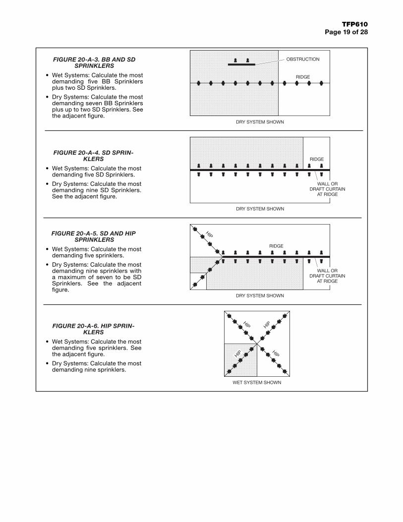
FIGURE 20-A-3. BB AND SD SPRINKLERS
• Wet Systems: Calculate the most demanding five BB Sprinklers plus two SD Sprinklers.
• Dry Systems: Calculate the most demanding seven BB Sprinklers plus up to two SD Sprinklers. See the adjacent figure.
FIGURE 20-A-4. SD SPRIN-KLERS
• Wet Systems: Calculate the most demanding five SD Sprinklers.
• Dry Systems: Calculate the most demanding nine SD Sprinklers. See the adjacent figure.
FIGURE 20-A-5. SD AND HIP SPRINKLERS
• Wet Systems: Calculate the most demanding five sprinklers.
• Dry Systems: Calculate the most demanding nine sprinklers with a maximum of seven to be SD Sprinklers. See the adjacent figure.
FIGURE 20-A-6. HIP SPRIN-KLERS
• Wet Systems: Calculate the most demanding five sprinklers. See the adjacent figure.
• Dry Systems: Calculate the most demanding nine sprinklers.
TFP610Page 20 of 28
DRY SYSTEM SHOWN
WALLS ORDRAFT
CURTAINS
RIDGE
DRY SYSTEM SHOWN
RIDGE
DRY SYSTEM SHOWN
OBSTRUCTION
RIDGE
DRY SYSTEM SHOWN
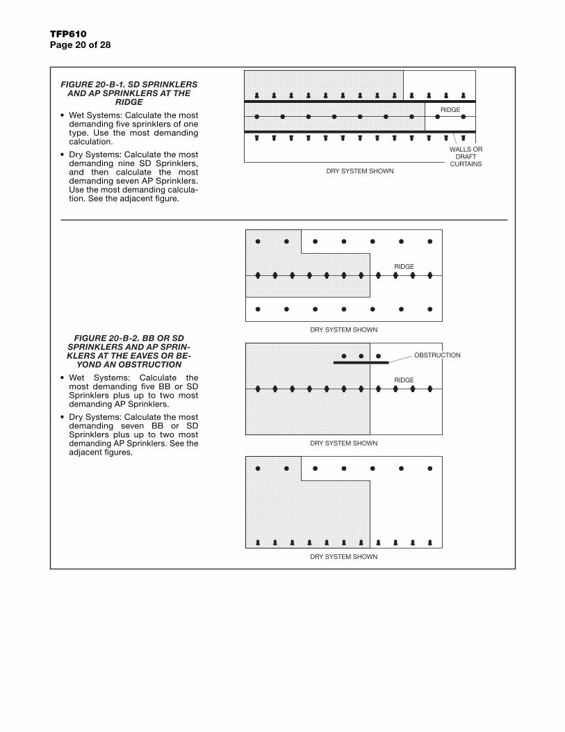
FIGURE 20-B-1. SD SPRINKLERS AND AP SPRINKLERS AT THE
RIDGE
• Wet Systems: Calculate the most demanding five sprinklers of one type. Use the most demanding calculation.
• Dry Systems: Calculate the most demanding nine SD Sprinklers, and then calculate the most demanding seven AP Sprinklers. Use the most demanding calcula-tion. See the adjacent figure.
FIGURE 20-B-2. BB OR SD SPRINKLERS AND AP SPRIN-KLERS AT THE EAVES OR BE-
YOND AN OBSTRUCTION
• Wet Systems: Calculate the most demanding five BB or SD Sprinklers plus up to two most demanding AP Sprinklers.
• Dry Systems: Calculate the most demanding seven BB or SD Sprinklers plus up to two most demanding AP Sprinklers. See the adjacent figures.
TFP610Page 21 of 28
AREA 2WITH AP
SPRINKLERS
AREA 1WITH BB
SPRINKLERS
AREA 3WITH AP
SPRINKLERS
MINIMUMSEPARATION15'-0" (4,6 m)
STAGGEREDSPACING WHEN
MORE THANONE ROW
DRY SYSTEM SHOWN
RIDGE
WALL ORDRAFT
CURTAIN
MINIMUMSEPARATION15'-0" (4,6 m)
AREA 1WITH BB & SDSPRINKLERS
AREA 2WITH AP
SPRINKLERS
AREA 3WITH AP
SPRINKLERS
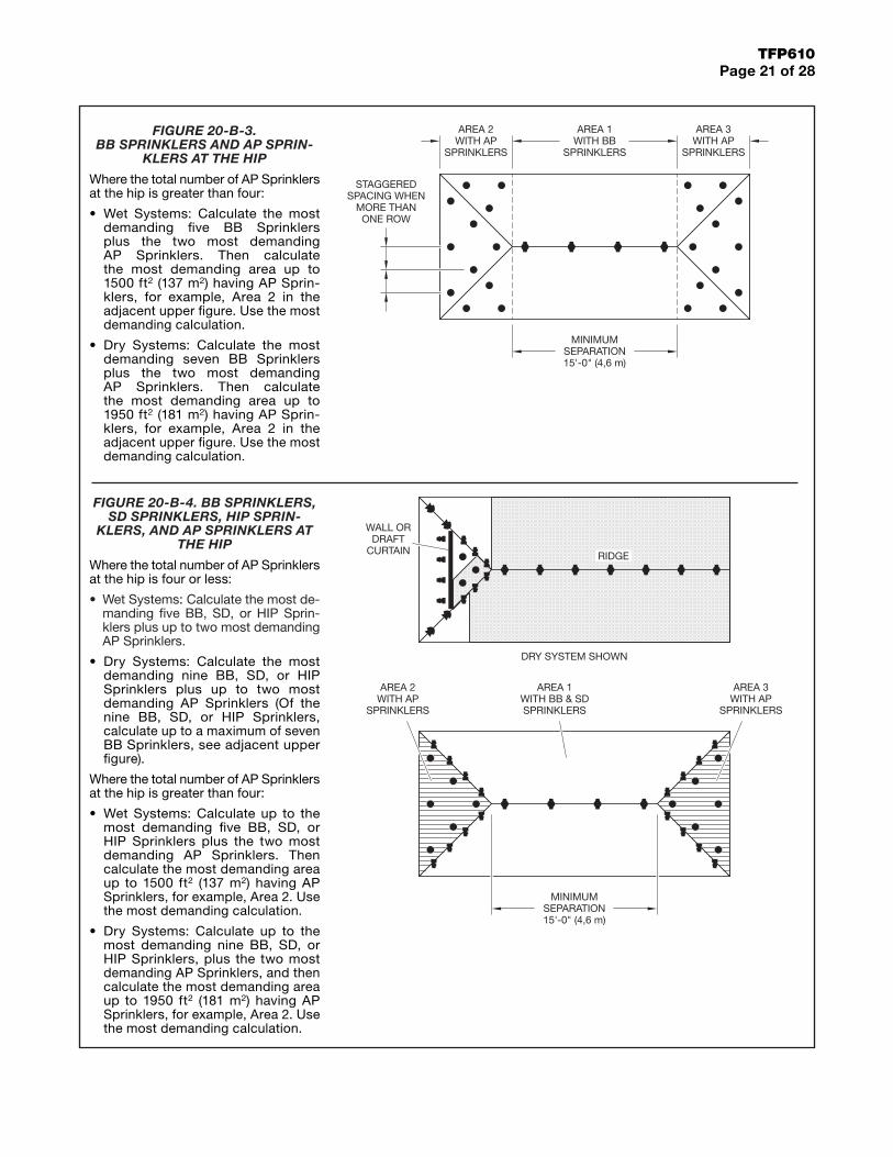
FIGURE 20-B-3. BB SPRINKLERS AND AP SPRIN-
KLERS AT THE HIP
Where the total number of AP Sprinklers at the hip is greater than four:
• Wet Systems: Calculate the most demanding five BB Sprinklers plus the two most demanding AP Sprinklers. Then calculate the most demanding area up to 1500 ft2 (137 m2) having AP Sprin-klers, for example, Area 2 in the adjacent upper figure. Use the most demanding calculation.
• Dry Systems: Calculate the most demanding seven BB Sprinklers plus the two most demanding AP Sprinklers. Then calculate the most demanding area up to 1950 ft2 (181 m2) having AP Sprin-klers, for example, Area 2 in the adjacent upper figure. Use the most demanding calculation.
FIGURE 20-B-4. BB SPRINKLERS, SD SPRINKLERS, HIP SPRIN-
KLERS, AND AP SPRINKLERS AT THE HIP
Where the total number of AP Sprinklers at the hip is four or less:
• Wet Systems: Calculate the most de-manding five BB, SD, or HIP Sprin-klers plus up to two most demanding AP Sprinklers.
• Dry Systems: Calculate the most demanding nine BB, SD, or HIP Sprinklers plus up to two most demanding AP Sprinklers (Of the nine BB, SD, or HIP Sprinklers, calculate up to a maximum of seven BB Sprinklers, see adjacent upper figure).
Where the total number of AP Sprinklers at the hip is greater than four:
• Wet Systems: Calculate up to the most demanding five BB, SD, or HIP Sprinklers plus the two most demanding AP Sprinklers. Then calculate the most demanding area up to 1500 ft2 (137 m2) having AP Sprinklers, for example, Area 2. Use the most demanding calculation.
• Dry Systems: Calculate up to the most demanding nine BB, SD, or HIP Sprinklers, plus the two most demanding AP Sprinklers, and then calculate the most demanding area up to 1950 ft2 (181 m2) having AP Sprinklers, for example, Area 2. Use the most demanding calculation.
TFP610Page 22 of 28
APSPRINKLERS(4 OR LESS)
APSPRINKLERS(4 OR LESS)
APSPRINKLERS(4 OR LESS)
APSPRINKLERS(4 OR LESS)
RIDGE
WALL
RIDGE
DORMERBUILT ON TOPOF ROOF ORSHEATHING
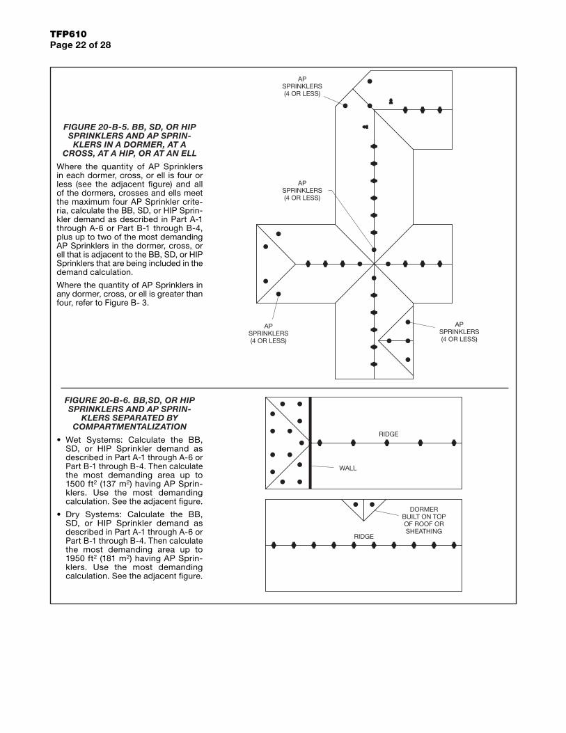
FIGURE 20-B-5. BB, SD, OR HIP SPRINKLERS AND AP SPRIN-
KLERS IN A DORMER, AT A CROSS, AT A HIP, OR AT AN ELL
Where the quantity of AP Sprinklers in each dormer, cross, or ell is four or less (see the adjacent figure) and all of the dormers, crosses and ells meet the maximum four AP Sprinkler crite-ria, calculate the BB, SD, or HIP Sprin-kler demand as described in Part A-1 through A-6 or Part B-1 through B-4, plus up to two of the most demanding AP Sprinklers in the dormer, cross, or ell that is adjacent to the BB, SD, or HIP Sprinklers that are being included in the demand calculation.
Where the quantity of AP Sprinklers in any dormer, cross, or ell is greater than four, refer to Figure B- 3.
FIGURE 20-B-6. BB,SD, OR HIP SPRINKLERS AND AP SPRIN-
KLERS SEPARATED BY COMPARTMENTALIZATION
• Wet Systems: Calculate the BB, SD, or HIP Sprinkler demand as described in Part A-1 through A-6 or Part B-1 through B-4. Then calculate the most demanding area up to 1500 ft2 (137 m2) having AP Sprin-klers. Use the most demanding calculation. See the adjacent figure.
• Dry Systems: Calculate the BB, SD, or HIP Sprinkler demand as described in Part A-1 through A-6 or Part B-1 through B-4. Then calculate the most demanding area up to 1950 ft2 (181 m2) having AP Sprin-klers. Use the most demanding calculation. See the adjacent figure.
TFP610Page 23 of 28
DRY SYSTEM SHOWN
WALLS ORDRAFT
CURTAINS
RIDGE
DRY SYSTEM SHOWN
OBSTRUCTION
RIDGE
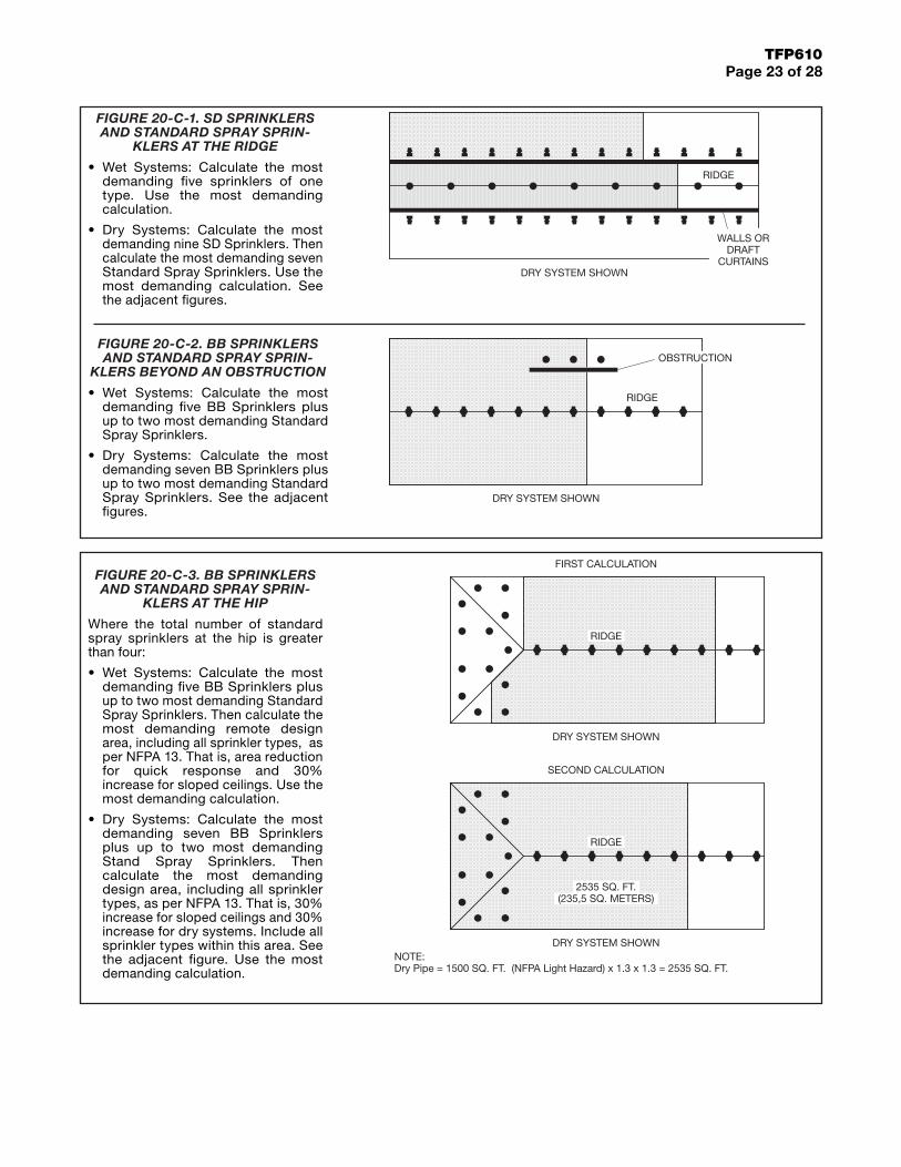
FIGURE 20-C-1. SD SPRINKLERS AND STANDARD SPRAY SPRIN-
KLERS AT THE RIDGE
• Wet Systems: Calculate the most demanding five sprinklers of one type. Use the most demanding calculation.
• Dry Systems: Calculate the most demanding nine SD Sprinklers. Then calculate the most demanding seven Standard Spray Sprinklers. Use the most demanding calculation. See the adjacent figures.
FIGURE 20-C-2. BB SPRINKLERS AND STANDARD SPRAY SPRIN-
KLERS BEYOND AN OBSTRUCTION
• Wet Systems: Calculate the most demanding five BB Sprinklers plus up to two most demanding Standard Spray Sprinklers.
• Dry Systems: Calculate the most demanding seven BB Sprinklers plus up to two most demanding Standard Spray Sprinklers. See the adjacent figures.
DRY SYSTEM SHOWN
RIDGE
2535 SQ. FT.(235,5 SQ. METERS)
SECOND CALCULATION
DRY SYSTEM SHOWN
RIDGE
FIRST CALCULATION
NOTE:Dry Pipe = 1500 SQ. FT. (NFPA Light Hazard) x 1.3 x 1.3 = 2535 SQ. FT.
FIGURE 20-C-3. BB SPRINKLERS AND STANDARD SPRAY SPRIN-
KLERS AT THE HIP
Where the total number of standard spray sprinklers at the hip is greater than four:
• Wet Systems: Calculate the most demanding five BB Sprinklers plus up to two most demanding Standard Spray Sprinklers. Then calculate the most demanding remote design area, including all sprinkler types, as per NFPA 13. That is, area reduction for quick response and 30% increase for sloped ceilings. Use the most demanding calculation.
• Dry Systems: Calculate the most demanding seven BB Sprinklers plus up to two most demanding Stand Spray Sprinklers. Then calculate the most demanding design area, including all sprinkler types, as per NFPA 13. That is, 30% increase for sloped ceilings and 30% increase for dry systems. Include all sprinkler types within this area. See the adjacent figure. Use the most demanding calculation.

TFP610Page 24 of 28
DRY SYSTEM SHOWN
DRY SYSTEM SHOWN
RIDGE
WALL ORDRAFT
CURTAIN
RIDGE
2535 SQ. FT.(235,5 SQ. METERS)
DRY SYSTEM SHOWN
RIDGE
FIRST CALCULATION
SECOND CALCULATION
NOTE:Dry Pipe = 1500 SQ. FT. (NFPA Light Hazard) x 1.3 x 1.3 = 2535 SQ. FT.
FIGURE 20-C-4. BB SPRINKLERS, SD SPRINKLERS, HIP SPRIN-
KLERS, AND STANDARD SPRAY SPRINKLERS AT THE HIP
Where the total number of Standard Spray Sprinklers at the hip is four or less:
• Wet Systems: Calculate the most demanding five BB, SD, or HIP Sprin-klers plus up to two most demanding Standard Spray Sprinklers.
• Dry Systems: Calculate the most demanding nine BB, SD, or HIP Sprin-klers plus up to two most demand-ing Standard Spray Sprinklers . Of the nine BB,SD, or HIP Sprinklers, calcu-late up to a maximum of seven BB Sprinklers. See the adjacent upper figure.
Where the total number of standard spray sprinklers at the hip is greater than four:
• Wet Systems: Calculate the most demanding five BB, SD, or HIP Sprin-klers plus up to two most demand-ing Standard Spray Sprinklers. Then calculate the most demanding remote design area, including all sprinklers types, as per NFPA 13. That is, area reduction for quick response and 30% increase for sloped ceilings. Use the most demanding calculation.
• Dry Systems: Calculate the most demanding nine BB, SD, or HIP Sprin-klers plus up to two most demand-ing Standard Spray Sprinklers. Of the nine BB,SD, or HIP Sprinklers, cal-culate up to a maximum of seven BB Sprinklers. See the adjacent upper fig-ure. Then calculate the most demand-ing design area, including all sprinkler types, as per NFPA 13. That is, 30% increase for sloped ceilings and 30% increase for dry systems. Include all sprinkler types within this area. See the adjacent figure.

TFP610Page 25 of 28
STANDARD SPRAYSPRINKLERS(4 OR LESS)
STANDARD SPRAYSPRINKLERS(4 OR LESS)
STANDARD SPRAYSPRINKLERS(4 OR LESS)
STANDARD SPRAYSPRINKLERS(4 OR LESS)
RIDGE
WALL
RIDGE
DORMERBUILT ON TOPOF ROOF ORSHEATHING
FIGURE 20-C-6. BB, SD, OR HIP SPRINKLERS AND STANDARD SPRINKLERS SEPARATED BY
COMPARTMENTALIZATION
Calculate the Attic Sprinkler demand as described in Part A-1 through A-6 or Part C-1 through C-4, and then calcu-late the Standard Spray Sprinklers per NFPA 13. Use the most demanding cal-culation. See the adjacent figure.
FIGURE 20-C-5. BB, SD, OR HIP SPRINKLERS AND STANDARD
SPRAY SPRINKLERS IN A DOR-MER, AT A CROSS, AT A HIP, OR
AT AN ELL
Where the quantity of standard spray sprinklers in each dormer, cross, or ell is four or less (see the adjacent figure) and all of the dormers, crosses and ells meet the maximum four standard sprin-kler criteria, calculate the Attic Sprin-kler demand as described in Part A-1 through A-6 or Part B-1 through B-4, plus up to two of the most demanding standard spray sprinklers in the dormer, cross, or ell that is adjacent to the Attic Sprinklers that are being included in the demand calculation.
Where the quantity of standard spray sprinklers in any dormer, cross, or ell is greater than four, refer to Figure C-3.
TFP610Page 26 of 28
100' (25,4 m)
60' (15,2 m) 20'(5,1 m)
20'(5,1 m)
40'(10,2 m)
20'(5,1 m)
60' (15,2 m)
100' (25,4 m)20'
(5,1 m)
12
12
Calculation 1
Calculation 240'
(10,2 m)
40'(10,2 m)
20'(5,1 m)
100' (25,4 m)
60' (15,2 m)
Calculation 2
20'(5,1 m)
40'(10,2 m)
20'(5,1 m)
100' (25,4 m)
60' (15,2 m)
12
12
Calculation 1
20'(5,1 m)
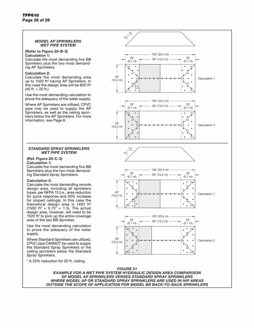
MODEL AP SPRINKLERS WET PIPE SYSTEM
(Refer to Figure 20-B-3)Calculation 1:Calculate the most demanding five BB Sprinklers plus the two most demand-ing AP Sprinklers.
Calculation 2:Calculate the most demanding area up to 1500 ft² having AP Sprinklers. In this case the design area will be 800 ft² (40 ft. × 20 ft.)
Use the most demanding calculation to prove the adequacy of the water supply.
Where AP Sprinklers are utilized, CPVC pipe may be used to supply the AP Sprinklers, as well as the ceiling sprin-klers below the AP Sprinklers. For more information, see Page 6.
STANDARD SPRAY SPRINKLERS WET PIPE SYSTEM
(Ref. Figure 20-C-3)Calculation 1:Calculate the most demanding five BB Sprinklers plus the two most demand-ing Standard Spray Sprinklers.
Calculation 2:Calculate the most demanding remote design area, including all sprinklers types, per NFPA 13 (i.e., area reduction for quick response and 30% increase for sloped ceilings). In this case the theoretical design area is 1463 ft² (1500 ft² × 0.75* × 1.3). The actual design area, however, will need to be 1520 ft² to pick up the entire coverage area of the last BB Sprinkler.
Use the most demanding calculation to prove the adequacy of the water supply.
Where Standard Sprinklers are utilized, CPVC pipe CANNOT be used to supply the Standard Spray Sprinklers or the ceiling sprinklers below the Standard Spray Sprinklers.
* A 25% reduction for 20 ft. ceiling.
FIGURE 21 EXAMPLE FOR A WET PIPE SYSTEM HYDRAULIC DESIGN AREA COMPARISON
OF MODEL AP SPRINKLERS VERSES STANDARD SPRAY SPRINKLERS WHERE MODEL AP OR STANDARD SPRAY SPRINKLERS ARE USED IN HIP AREAS
OUTSIDE THE SCOPE OF APPLICATION FOR MODEL BB BACK-TO-BACK SPRINKLERS

TFP610Page 27 of 28
100' (25,4 m)
60' (15,2 m)
40'(10,2 m)
20'(5,1 m)
Calculation 2
20'(5,1 m)
60' (15,2 m)
100' (25,4 m)
40'(10,2 m)
20'(5,1 m)
Calculation 1
20'(5,1 m)
12
12
40'(10,2 m)
20'(5,1 m)
40'(10,2 m)
20'(5,1 m)
12
12
Calculation 2
100' (25,4 m)
60' (15,2 m) 20'(5,1 m)
Calculation 1
100' (25,4 m)
60' (15,2 m) 20'(5,1 m)
MODEL AP SPRINKLERS DRY PIPE SYSTEM
(Ref. Figure 20-B-3)Calculation 1:Calculate the most demanding seven BB Sprinklers plus the two most demanding AP Sprinklers.
Calculation 2:Calculate the most demanding area up to 1950 ft2 having AP Sprinklers. In this case the design area will be 800 ft2 (40 ft. x 20 ft.)
Use the most demanding calculation to prove the adequacy of the water supply.
STANDARD SPRAY SPRINKLERS DRY PIPE SYSTEM
(Ref. Figure 20-C-3)Calculation 1:Calculate the most demanding seven BB Sprinklers plus the two most demanding Standard Spray Sprinklers.
Calculation 2:Calculate the most demanding remote design area, including all sprinklers types, as per NFPA 13. That is, 30% increase for sloped ceilings and 30% increase for dry systems. In this case the theoretical design area will be 2535 ft² (1500 ft² × 1.3 × 1.3). The actual design area, however, will need to be 2720 ft² to pick up the entire coverage area of the last BB Sprinkler.
Use the most demanding calculation to prove the adequacy of the water supply.
FIGURE 22 EXAMPLE FOR A DRY PIPE SYSTEM HYDRAULIC DESIGN AREA COMPARISON
OF MODEL AP SPRINKLERS VERSES STANDARD SPRAY SPRINKLERS WHERE MODEL AP OR STANDARD SPRAY SPRINKLERS ARE USED IN HIP AREAS
OUTSIDE THE SCOPE OF APPLICATION FOR MODEL BB BACK-TO-BACK SPRINKLERS

GLOBAL HEADQUARTERS | 1400 Pennbrook Parkway, Lansdale, PA 19446 | Telephone +1-215-362-0700
TFP610Page 28 of 28
Copyright © 2017 Tyco Fire Products, LP. All rights reserved.TEFLON is a registered trademark of DuPont, MONEL is a registered trademark of Special metals Corporation BLAZEMASTER is a registered trademark of The Lubrizol Corporation