Model Answers Winter 2018 Examinations Subject &...
22
MAHARASHTRA STATE BOARD OF TECHNICAL EDUCATION (Autonomous) (ISO/IEC-27001-2013 Certified) Model Answers Winter – 2018 Examinations Subject & Code: Switchgear & Protection (17508) 1 of 22 Important Instructions to examiners: 1) The answers should be examined by key words and not as word-to-word as given in the model answer scheme. 2) The model answer and the answer written by candidate may vary but the examiner may try to assess the understanding level of the candidate. 3) The language errors such as grammatical, spelling errors should not be given more importance (Not applicable for subject English and Communication Skills). 4) While assessing figures, examiner may give credit for principal components indicated in the figure. The figures drawn by candidate and model answer may vary. The examiner may give credit for any equivalent figure drawn. 5) Credits may be given step wise for numerical problems. In some cases, the assumed constant values may vary and there may be some difference in the candidate’s answers and model answer. 6) In case of some questions credit may be given by judgement on part of examiner of relevant answer based on candidate’s understanding. 7) For programming language papers, credit may be given to any other program based on equivalent concept.
Transcript of Model Answers Winter 2018 Examinations Subject &...

MAHARASHTRA STATE BOARD OF TECHNICAL EDUCATION
(Autonomous)
(ISO/IEC-27001-2013 Certified)
Model Answers
Winter – 2018 Examinations
Subject & Code: Switchgear & Protection (17508)
1 of 22
Important Instructions to examiners:
1) The answers should be examined by key words and not as word-to-word as given in the model
answer scheme.
2) The model answer and the answer written by candidate may vary but the examiner may try to assess
the understanding level of the candidate.
3) The language errors such as grammatical, spelling errors should not be given more importance (Not
applicable for subject English and Communication Skills).
4) While assessing figures, examiner may give credit for principal components indicated in the figure.
The figures drawn by candidate and model answer may vary. The examiner may give credit for any
equivalent figure drawn.
5) Credits may be given step wise for numerical problems. In some cases, the assumed constant values
may vary and there may be some difference in the candidate’s answers and model answer.
6) In case of some questions credit may be given by judgement on part of examiner of relevant answer
based on candidate’s understanding.
7) For programming language papers, credit may be given to any other program based on equivalent
concept.

MAHARASHTRA STATE BOARD OF TECHNICAL EDUCATION
(Autonomous)
(ISO/IEC-27001-2013 Certified)
Model Answers
Winter – 2018 Examinations
Subject & Code: Switchgear & Protection (17508)
2 of 22
1 a) Attempt any THREE of the following: 12
1 a) i) Explain current limiting reactor.
Ans:
Current Limiting Reactor:
A Reactor is a coil of number of turns designed to have large inductance with
negligible ohmic resistance connected in series with equipment to limit the short
circuit current.
Generally reactance of the system under fault condition is low and fault currents may
rise to dangerously high values. In order to limit the fault current to reasonable
magnitudes which the CB can handle, additional reactances (reactors) are connected in
series with system at suitable points. These reactors are called “Current Limiting
Reactors”.
Classification of reactors : 1) Generator reactors
2) Feeder reactors
3) Busbar reactors
i) Ring Systems
ii) Tie bar system
1 mark
2 marks
1 mark
1 a) ii) What are causes of faults in power system? State any four harmful effects of faults.
Ans:
Causes of faults in power systems:
1) Over voltages due to direct lightning strokes.
2) Over voltages due to switching surges.
3) Falling of external conducting objects, tree branches etc. on conducting lines.
4) Accumulation of dust, dirt etc. on exposed components as lines, insulators etc.
5) Perching of birds on lines, insulators or other components.
6) Ill-maintained sections of the power systems.
7) Heavy unbalanced loading on three phase lines even for short times.
8) Prolonged unbalanced loading conditions leading to overheating (due to
harmonics).
9) Failure of joints.
10) Open circuited line or broken conductors.
11) Mechanical damage to components of the power systems.
12) Unusually severe atmospheric conditions as storm, rains, too high humidity,
13) Defective/improper selection of components used and faulty design of the
power system sections.
14) Failure of insulation of components and equipment parts.
15) Accidents.
16) Over temperature.
17) Excessive internal and external stresses.
Effects of faults:
1) Heavy short circuits lead to damage to equipment mechanically and
electrically.
2) Arcing during faults leads to fire hazards.
3) Heavy drop in the supply voltage to loads leading to their mal-operation.
½ mark for
each cause
maximum 2
marks,
½ mark for
each effect
maximum 2
marks

MAHARASHTRA STATE BOARD OF TECHNICAL EDUCATION
(Autonomous)
(ISO/IEC-27001-2013 Certified)
Model Answers
Winter – 2018 Examinations
Subject & Code: Switchgear & Protection (17508)
3 of 22
4) Overheated machines due to unbalanced supply voltages.
5) Loss of revenue to supply agency owing to stoppage of supply.
6) Loss of system stability due to generators losing synchronism.
7) Distress load shedding.
1 a) iii) Define:
(1) Plug setting multiplier
(2) Time setting multiplier
Ans:
Plug setting multiplier (PSM):
It is related to the current setting of the overcurrent relays.
The plug setting multiplier is defined as the ratio of the ‘transformed fault current on
the relay side’ to the ‘relay pickup current’.
PSM = 𝑡𝑟𝑎𝑛𝑠𝑓𝑜𝑟𝑚𝑒𝑑 𝑓𝑎𝑢𝑙𝑡 𝑐𝑢𝑟𝑟𝑒𝑛𝑡 𝑜𝑛 𝐶𝑇 𝑠𝑒𝑐𝑜𝑛𝑑𝑎𝑟𝑦 𝑠𝑖𝑑𝑒
𝑟𝑒𝑙𝑎𝑦 𝑐𝑢𝑟𝑟𝑒𝑛𝑡 𝑠𝑒𝑡𝑡𝑖𝑛𝑔
= 𝑓𝑎𝑢𝑙𝑡 𝑐𝑢𝑟𝑟𝑒𝑛𝑡 𝑜𝑛 𝐶𝑇 𝑝𝑟𝑖𝑚𝑎𝑟𝑦 𝑠𝑖𝑑𝑒 (𝑖.𝑒 𝑙𝑖𝑛𝑒 𝑓𝑎𝑢𝑙𝑡 𝑐𝑢𝑟𝑟𝑒𝑛𝑡)
𝑟𝑒𝑙𝑎𝑦 𝑐𝑢𝑟𝑟𝑒𝑛𝑡 𝑠𝑒𝑡𝑡𝑖𝑛𝑔 x 𝐶𝑇 𝑟𝑎𝑡𝑖𝑜
Time setting multiplier (TSM): It is related to the operating time of the relay during faults. The angular distance
through which the relay disc travels during faults before the trip contacts close is
varied to get different times of operation of the relay. This is time setting. These times
of motion of the disc are set in 10 steps starting with maximum time setting of 1 (when
disc is set farthest) to minimum (when disc is nearest) of 0 (instantaneous). For
example if the angular travel from trip contacts is set to maximum then TSM =1, then
for a particular PSM if the operating time of relay is 1 second then for the same PSM if
the TSM is set to 0.4 then the time of operation will be (1 second x TSM)
= 1 x 0.4 = 0.4 seconds.
Thus TSM is used to define the steps for time setting of relay operation.
1 mark
1 mark
1 mark
1 mark
1 a) iv) Explain the phenomenon of lightning.
Ans:
Phenomenon of lightning:
An electric discharge between cloud and earth, between clouds or between the charge
centres of the same cloud is known as “Lightning”.
Lightning takes place when the clouds acquire charge. During the uprush of warm
moist air from earth, the friction between the air and the tiny particles of water causes
building up of charges. When drops of water are formed, the larger drops become
positively charged and the smaller drops become negatively charged. When the drops
of water accumulate, they form clouds and hence cloud may possess either a positive
or a negative charge, depending upon the charge of water drops they contain. The
charge on a cloud may become so great that it may discharge to another cloud or earth
through air medium, after its electrical breakdown. Such a discharge is called as
lightning.
When the charged cloud passes over the earth, it induces equal and opposite charge on
1 mark for
definition
1 mark for
process of
charging

MAHARASHTRA STATE BOARD OF TECHNICAL EDUCATION
(Autonomous)
(ISO/IEC-27001-2013 Certified)
Model Answers
Winter – 2018 Examinations
Subject & Code: Switchgear & Protection (17508)
4 of 22
the earth below. As the charge acquired by the cloud increases, the potential between
cloud and earth increases and therefore the potential gradient in the air between them
increases. When the potential gradient becomes more than the dielectric strength of the
air medium, the electrical breakdown of the air takes place and the lightning stroke
starts. The lightning stroke mechanism is as follows:
(i) As soon as the air near the cloud breaks down, a streamer called “leader
streamer” or “pilot streamer” starts from cloud towards the earth and carries
charge with it. So far the cloud feeds enough charge to maintain the gradient
above the dielectric strength of air at the tip of the leader streamer; the leader
streamer continues its journey towards the earth.
(ii) As the leader streamer moves towards earth, it is accompanied by points of
luminescence which travel in jumps giving rise to stepped leaders. The stepped
leaders have sufficient luminosity and give rise to first visual phenomenon of
discharge.
(iii) As the leader streamer reaches near earth, a return streamer shoots up from the
earth to the cloud, following the same ionized path as that of leader streamer.
This phenomenon causes a sudden spark which we call lightning.
2 marks for
Stroke
mechanism
1 b) Attempt any ONE of the following: 06
1 b) i) A station operating at 33kV is divided into section P and Q. Section P consist of 3
generators 15MVA each having reactance of 15% and section Q is ped fed from grid
through a 750MVA transformer of 8% reactance. The C.B’s have each a rupturing
capacity 750 MVA. Determine the reactance of the reactor to prevent the breakers
being overloaded if a symmectrical short circuit occurs on an out going feeder
connected to P.
Ans:
Figure shows the single-line diagram of the network. Suppose the fault occurs at point
F on an outgoing feeder connected to section P. As per the given condition, the short
circuit MVA at F should not exceed 750 MVA.
Since the maximum power rating is 750MVA of transformer, let us choose 750MVA
as base MVA.
Base MVA = 750MVA
%Reactance of each of the generator on the base MVA =750
15× 15 = 750%
1 mark for
network
diagram
1 mark for
reactances on
base MVA

MAHARASHTRA STATE BOARD OF TECHNICAL EDUCATION
(Autonomous)
(ISO/IEC-27001-2013 Certified)
Model Answers
Winter – 2018 Examinations
Subject & Code: Switchgear & Protection (17508)
5 of 22
%XA=%XB=%XC=750%
% Reactance of the transformer on base MVA is
%XT =750
750× 8 = 8%
Suppose the required reactance of the reactor is X% on 750MVA base. When the fault
occurs at point F, the reactance diagram at the selected base MVA will be as shown in
the following figure.
The reactances of the three generators are in parallel & their equivalent reactance is
given by, =750
3= 250%
The circuit is then simplified as shown in the figure.
Total percentage reactance from generator neutral to fault point F is,
=(250)(𝑋+8)
250+𝑋+8
Now fault MVA at F should not exceed 750MVA, otherwise the circuit breakers will
be overloaded.
Fault MVA = 𝐵𝑎𝑠𝑒 𝑀𝑉𝐴 ×100
𝑅𝑒𝑞𝑢𝑖𝑟𝑒𝑑 % 𝑅𝑒𝑎𝑐𝑡𝑎𝑛𝑐𝑒
750 = 750 ×100
𝑅𝑒𝑞𝑢𝑖𝑟𝑒𝑑 % 𝑅𝑒𝑎𝑐𝑡𝑎𝑛𝑐𝑒
Required % Reactance = 100%
This means that total % Reactance from generator neutral to fault point F should be
100%
i.e 100 =(250)(𝑋+8)
250+𝑋+8
250+𝑋+8
2.5= 𝑋 + 8
100 + 0.4𝑋 + 3.2 = 𝑋 + 8
100 + 3.2 − 8 = 𝑋 − 0.4𝑋 = 0.6𝑋
𝑋 = 158.67%
But %𝑅𝑒𝑎𝑐𝑡𝑎𝑛𝑐𝑒 = (𝐵𝑎𝑠𝑒 𝑘𝑉𝐴)(𝑅𝑒𝑎𝑐𝑡𝑎𝑛𝑐𝑒 𝑖𝑛 Ω)
10(𝑘𝑉)2
=(𝐵𝑎𝑠𝑒 𝑀𝑉𝐴×1000)(𝑋 𝑖𝑛 Ω)
10(𝑘𝑉)2
158.67 =750×1000×𝑋
10(33)2
𝑋 =158.67×10×332
750×1000
Reactance of Reactor in ohm = X = 2.3039Ω
1 mark for
reactance
diagram
1 mark
1 mark
1 mark
1 b) ii) A 3, 66/11 kV, star-delta connected transformer is protected by Merz-Price system.
The CTs on LV side have a ratio of 400/5. Find the ratio of the CTs on the HV side.
Ans:
The CTs on LV side are connected in star as transformer windings are in delta.
MAHARASHTRA STATE BOARD OF TECHNICAL EDUCATION
(Autonomous)
(ISO/IEC-27001-2013 Certified)
Model Answers
Winter – 2018 Examinations
Subject & Code: Switchgear & Protection (17508)
6 of 22
Whereas those on HV side are in delta as the transformer windings are in star on that
side.
Assume CT line current on LV side to be 5 A and then that on HV side will also
be 5 A. But HV side CTs are in delta. Hence the HV side CT current will be
(CT line current)/√3 = 5/√3 A.
Assume line current (for convenience) of 400 A on LV side (delta side) of
transformer. When transformed to HV side the line current will be ILht given by
√3 x 66 x ILht = √3 x 11 x 400
ILht = (11/66)x(400) = 66.67 A.
On HV side the CT primary current is 66.67 A and CT secondary current is 5/√3 A,
hence the CT ratio is 66.67/(5/√3) = (66.67√3/5) = 115.47/5.
2 marks
2 marks
2 marks
2 Attempt any FOUR of the following: 16
2 a) Define:
i) Arc voltage,
ii) Recovery voltage,
iii) Restriking voltage,
iv) RRRV
Ans:
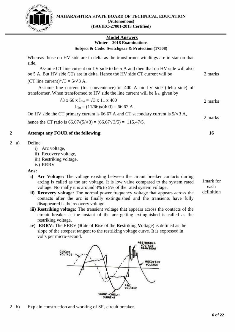
i) Arc Voltage: The voltage existing between the circuit breaker contacts during
arcing is called as the arc voltage. It is low value compared to the system rated
voltage. Normally it is around 3% to 5% of the rated system voltage.
ii) Recovery voltage: The normal power frequency voltage that appears across the
contacts after the arc is finally extinguished and the transients have fully
disappeared is the recovery voltage.
iii) Restriking voltage: The transient voltage that appears across the contacts of the
circuit breaker at the instant of the arc getting extinguished is called as the
restriking voltage.
iv) RRRV: The RRRV (Rate of Rise of the Restriking Voltage) is defined as the
slope of the steepest tangent to the restriking voltage curve. It is expressed in
volts per micro-second.
1mark for
each
definition
2 b) Explain construction and working of SF6 circuit breaker.

MAHARASHTRA STATE BOARD OF TECHNICAL EDUCATION
(Autonomous)
(ISO/IEC-27001-2013 Certified)
Model Answers
Winter – 2018 Examinations
Subject & Code: Switchgear & Protection (17508)
7 of 22
Ans:
Construction:
A sulphur hexafluoride (SF6) circuit breaker consists of fixed and moving contacts
enclosed in a chamber. The chamber is called arc interruption chamber, which contains
the sulphur hexafluoride (SF6) gas. This chamber is connected to sulphur hexafluoride
(SF6) gas reservoir. A valve mechanism is there to permit the gas to the arc
interruption chamber. When the contacts of breaker are opened, the valve mechanism
permits a high-pressure sulphur hexafluoride (SF6) gas from the reservoir to flow
towards the arc interruption chamber.
The fixed contact is a hollow cylindrical current carrying contact fitted with an arcing
horn. The moving contact is also a hollow cylinder with rectangular holes in the sides.
The holes permit the sulphur hexafluoride gas (SF6) gas to let out through them after
flowing along and across the arc. The tips of fixed contact, moving contact and arcing
horn are coated with a copper-tungsten arc-resistant material. Since sulphur
hexafluoride gas (SF6) gas is costly, it is reconditioned and reclaimed using the
suitable auxiliary system after each operation of the breaker.
Working of SF6 circuit breaker:
Gas is compressed by the moving cylinder and is released through the nozzle and rapidly absorbs the free electrons to extinguish the arc formed. The moving cylinder (1) connected to moving contact (2) against the fixed piston (5).
Due to relative motion between (1) and (5) the gas gets compressed in enclosure (6)
and is released through nozzle for arc extinction. This happens by puffing action. At
current zero the diameter becomes too small and arc gets extinguished.
OR
Double pressure type breaker:
2 marks for
construction
1 mark for
diagram
1 mark for
working

MAHARASHTRA STATE BOARD OF TECHNICAL EDUCATION
(Autonomous)
(ISO/IEC-27001-2013 Certified)
Model Answers
Winter – 2018 Examinations
Subject & Code: Switchgear & Protection (17508)
8 of 22
Here the gas is made to flow from area P1 to P2 through a convergent-divergent nozzle.
The flowing gas covers the arc. In the divergent section the speed of the gas is very
high and carries away most of the heat and absorbs free electrons from the periphery of
arc that results in the reduction of diameter of arc, which becomes nearly zero at
current zero, leading to arc being extinguished. Finally the gas enters the contact space
increasing the dielectric strength.
2 c) Explain working of surge absorber with neat diagram.
Ans:
Surge Absorber:
Voltage transients or surges on the power system may originate from switching or
lightning. These surges set up traveling waves in the transmission lines. These
traveling waves may reach the terminals of expensive equipment in power system and
may cause damage to it.
This amount of damage caused by surges not only depends upon the amplitude of the
surge but also upon the steepness of its wavefront. The steeper the wavefront of the
surge, the more the damage caused to the equipment. To reduce the steepness of the
wavefront of a surge generally, surge absorbers are used.
A surge absorber is a protective device, which reduces the steepness of wavefront of a
surge by absorbing surge energy.
Some popular types of surge absorber used in power system are as under:
1. Condenser or capacitor surge absorber.
2. Inductor and resistance surge absorber.
3. Ferranti surge absorber.
Condenser or Capacitor Surge Absorber:
A condenser connected between the line and earth can act as a surge absorber. In
Figure, a capacitor is used as surge absorber to protect the transformer winding.
Since the reactance of a condenser is inversely proportional to frequency, it will be low
at high frequency and high at low frequency. The surges are of high frequency,
therefore, the capacitor acts as a short circuit and passes them directly to earth.
However, for power frequency, the reactance of the capacitor is very high and
practically no current flows to the ground.
Inductor and Resistance Surge Absorber: This type of surge absorber consists of a parallel combination of choke and resistance
connected in series with the line.
The choke offers high reactance to high frequencies (XL = 2 π f L). The surges have
1 mark for
definition
1 mark for
any one
diagram
2 marks for
working

MAHARASHTRA STATE BOARD OF TECHNICAL EDUCATION
(Autonomous)
(ISO/IEC-27001-2013 Certified)
Model Answers
Winter – 2018 Examinations
Subject & Code: Switchgear & Protection (17508)
9 of 22
high frequencies therefore, are forced to flow through the resistance R where the surge
energy is dissipated.
Ferranti Surge Absorber: It consists of an air cored inductor connected in series with the line. The inductor is
surrounded by but insulated from an earthed metallic cylinder called dissipator. This
arrangement is equivalent to a transformer with short-circuited secondary.
The inductor acts as the primary of transformer whereas the dissipator as the short-
circuited secondary. The energy of the surge is consumed in the dissipator in form of
heat due to transformer action. Generally, it is used for the protection of transformers.
2 d) Write down difference between equipment earthing and neutral earthing.
Ans:
Difference between Equipment earthing and Neutral earthing:
Sr.
No. Equipment earthing Neutral earthing
1
Connection of the non-current
carrying metallic parts of the
electrical equipment to earth is
called as equipment earthing.
Connection of the neutral point of
three phase transformer,
generators, motors etc. to earth is
neutral earthing.
2 It is provided for protection of human being from electric shocks.
It is provided for eliminating arching ground and over voltage surge.
3 It has nothing to do with stability Stability of the system is increased.
4
Equipment earthing is provided
through Pipe earthing, Plate
earthing.
Neutral earthing is provided
through solid earthing, resistance
earthing and reactance earthing.
5 It does not provide any means for protection system against earth fault.
It provides suitable means for
earth fault protection system.
6 It is an equipment earthing. It is a source or system earthing.
1 mark for
each of any
four points
= 4 marks
2 e) The current rating of a relay is 5A. PSM = 1.5, TSM = 0.5, C.T. ratio 500/5, fault
current = 6000A. Determine the operating time of the relay at TSM = 1, operating time
at various PSM are:
PSM 2 4 5 8 10 20
Operating time in sec 10 5 4 3 2.8 2.4
Ans:
Rated secondary current of C.T. = 5A
1 mark

MAHARASHTRA STATE BOARD OF TECHNICAL EDUCATION
(Autonomous)
(ISO/IEC-27001-2013 Certified)
Model Answers
Winter – 2018 Examinations
Subject & Code: Switchgear & Protection (17508)
10 of 22
Pick up current = 5 × 1.5 = 7.5𝐴
Fault current in relay coil = 6000 ×5
500= 60𝐴
∴ Plug setting multiplier (PSM) = 𝑓𝑎𝑢𝑙𝑡 𝑐𝑢𝑟𝑟𝑒𝑛𝑡 𝑖𝑛 𝑟𝑒𝑙𝑎𝑦 𝑐𝑜𝑖𝑙
𝑝𝑖𝑐𝑘−𝑢𝑝 𝑐𝑢𝑟𝑟𝑒𝑛𝑡
= 60
7.5= 8
Corresponding to PSM of 8 (consider given table), the time of operation is 3 seconds.
Actual relay operating time = 3 × 𝑡𝑖𝑚𝑒 𝑠𝑒𝑡𝑡𝑖𝑛𝑔 = 3 × 0.5 = 1.5 𝑠𝑒𝑐𝑜𝑛𝑑𝑠
1 mark
1 mark
1 mark
2 f)
∴ 𝑥 = 12.6 %
An 11kV, 100MVA alternator is grounded through a resistance of 4. The CTs have a
ratio 1000/5. The relay is set to operate when there is an out of balance current of 1 A.
What percentage of alternator winding will be protected by the percentage differential
protection?
Ans:
Let x% of winding be unprotected.
Earthing resistance r = 4 Ω
Voltage per phase = 11×1000
√3= 6350.8529 𝑣𝑜𝑙𝑡𝑠
Minimum fault current which will operate the relay = 1000
5× 1.0 = 200𝐴
E.m.f. induced in x % winding = 𝑉𝑝ℎ × 𝑥
100=
6350.85(𝑥)
100= 63.5085(𝑥)𝑣𝑜𝑙𝑡𝑠
Earth fault current which x% winding will cause = 63.5085(𝑥)
𝑟= 15.88(𝑥)
This current must be equal to minimum fault current which will operate the relay.
∴ 15.88(𝑥) = 200
So percentage of winding protected = 100 – 12.6 = 87.4 %
1 mark
1 mark
1 mark
1 mark
3 Attempt any FOUR of the following: 16
3 a) Describe the difference between fuse and MCCB.
Ans:
Difference between Fuse and MCCB:
Sr. No. Fuse MCCB
1 Fuse melts / fuses in case of
excessive load.
MCCB trips off in case of
excessive load.
2 Fuse needs to be replaced after
every operation.
MCCB is to be just put ON after
correcting the fault.
3 Porcelain base and top. Not
attractive.
Compact, small and attractive.
4 Works on melting / fusing due to
high temperature.
Works on bi–metal expansion or
induced magnetism.
5 Relatively economical than Relatively costlier than fuse.
1 mark for
each of any
four points
= 4 marks

MAHARASHTRA STATE BOARD OF TECHNICAL EDUCATION
(Autonomous)
(ISO/IEC-27001-2013 Certified)
Model Answers
Winter – 2018 Examinations
Subject & Code: Switchgear & Protection (17508)
11 of 22
MCCB.
6 Simple in construction. Complicated in construction.
7 Operating time is very small.
(0.002 sec or so)
Operating time is comparatively
large. (0.1 to 0.2 sec)
8 Risk in putting on the fuse
element.(Unsafe)
No risk in putting “ON” the
MCCB. (Safe).
9 Generally protects the load
against short-circuit.
Generally protects the load
against different types of faults.
3 b) Write down specification and applications of Air blast C. B. and Vacuum C. B.
Ans:
Specifications of Circuit Breaker:
i) Service type: Indoor / Outdoor
ii) No. of Poles: 1 or 3
iii) Nominal System Voltage:
iv) Highest System Voltage:
v) Rated normal current;
vi) Rated short-circuit breaking current (rms):
vii) Rated short-circuit making current (rms):
viii) Rated short-time current withstand capability for 3 sec:
ix) Rated insulation level:
x) S. C. Rating:
xi) No. of breaks per phase:
xii) Operating air / gas pressure:
xiii) Nominal frequency
Applications:
Air Blast Circuit Breaker:
Air blast circuit breakers are used in electrical systems operating at 132kV and above
upto 400kV.
Vacuum Circuit Breaker:
Vacuum circuit breakers are used in electrical systems operating at 11kV, 25kV and
33kV.
2 marks for
any four
specification
s
1 mark
1 mark
3 c) How can we use CT and PT for protection purpose?
Ans:
CT and PT for Protection purpose:
1 mark

MAHARASHTRA STATE BOARD OF TECHNICAL EDUCATION
(Autonomous)
(ISO/IEC-27001-2013 Certified)
Model Answers
Winter – 2018 Examinations
Subject & Code: Switchgear & Protection (17508)
12 of 22
Current transformer (CT) and Potential transformer (PT) are instrument transformers,
which are used in conjunction with protective relays for protection purpose.
The CT has fewer number of turns (usually single turn or simply a conductor bar) on
primary side and a large number of turns on the secondary side. Due to this difference
in turns, a large current on primary side is transformed into current of low safe value
on secondary side. The CT is connected with primary in series with power system
component carrying large current and secondary winding feeds proportionately
reduced current to protective relay.
Potential transformer (PT) has large number of turns on primary side and fewer
number of turns on the secondary side. Therefore, it steps down the primary voltage to
lower safe secondary voltage. The PT is connected with primary connected to high
voltage system bus and secondary winding feeds proportionately reduced voltage to
protective relay.
Protective relay is a device that detects abnormal condition in electrical system by
continuously measuring / monitoring the electrical quantities such as current, voltage
etc., which are different under normal and fault conditions. The current, voltage and
phase angle are the basic quantities which change during fault conditions. On the
occurrence of fault, the system voltage and current get affected. The CT and PT
provides the information about the changed system condition to the relay. The relay
determines the faulty condition and operates the trip contact as shown in the figure.
The trip circuit of circuit breaker is energised. The current flows through trip coil of
CB and the circuit breaker is tripped (opened) to disconnect the faulty part of system
from the healthy part. In this way the CT and PT can be used for protection purpose.
3 marks for
proper
explanation
3 d) Write down limitation of differential protection of transformer.
Ans:
Limitations of differential protection of transformer: 1) Due to the magnetization characteristics of the CTs used, the ratio errors change
with respect to the circulating currents. 2) The pilot wires used may vary in length due to which the unbalance in the
secondary circuit parameter (resistance) is created that result in improper scheme.
3) During heavy short circuit conditions the high currents create saturation of the flux in core of CTs that lead to abnormal relaying or unexpected behavior of the relaying circuit.
4) Tap changing may lead to change in settings & improper operation. 5) Inrush of magnetizing current may lead to inadvertent operation & hence the
settings are done for higher values of fault current (higher imbalance) due to which accuracy of sensing & operation is decreased.
1 mark for
each of any 4
limitations
= 4 Marks
3 e) State and explain the faults occur in the transformers.
Ans:
Sr. No. Type of fault Explanation
1 Earth fault Due to breakdown of insulation between live

MAHARASHTRA STATE BOARD OF TECHNICAL EDUCATION
(Autonomous)
(ISO/IEC-27001-2013 Certified)
Model Answers
Winter – 2018 Examinations
Subject & Code: Switchgear & Protection (17508)
13 of 22
conducting parts such as winding, terminals etc. and
earthed metallic parts such as core, tank etc. the
current is diverted to earth, causing earth fault. The
causes of earth fault are:
i) Electrical breakdown of insulation due to over-
voltage surges produced by lightning or switching
operations.
ii) Mechanical damage of insulation.
iii) Electrical or mechanical breakdown of bushings
iv) Insulation damage due to over-heating
2 Overloads/
Overheating
Sustained overloads cause additional losses in
windings, causing over-heating of windings.
Unbalanced loading cause additional magnetic losses
leading to over-heating of core and other mechanical
parts.
3 Incipient faults:
Phase to Phase,
Phase to
ground, low oil
level,
decomposition
of oil
Incipient faults are slowly developing faults, which if
not attended in time, can lead to severe faults.
i) Slow insulation degradation due to continuous over-
heating.
ii) Reduction in oil level due to leakage, which leads to
unequal cooling of transformer assembly, resulting
unequal thermal expansion and stresses.
iii) Degradation of oil over a period of service.
4 Saturation of
magnetic core
Over-voltage conditions lead to saturation of cores.
Since flux level is increased, the iron losses are
increased.
5 Faults in tap
changer
Mechanical problems in tap changer assembly lead to
faults in tap changer.
6 Inter turn fault When insulation breakdown of a winding takes place
and few turns of the same winding are short-
circuited, the inter-turn fault takes place.
1 mark for
each of any
four faults
= 4 marks
4 a) Attempt any THREE of the following: 12
4 a) i) How the alternator can be protected from inter-turn fault?
Ans:
Inter-turn fault Protection:
Figure shows scheme for one phase only. It is identical for other
phases. Under normal working condition, the two currents in the stator winding sections (S1 and S2) are identical and by virtue of the cross connected CT secondaries, the relay current is zero, hence no relay operation. But when one of the windings is faulty (inter turn fault) its current differs and hence the two CT secondary currents are different, due which the difference current is diverted through the relay coil to operate it, leading to isolation of the alternator from the power system.
2 marks for
description
2 marks for
diagram

MAHARASHTRA STATE BOARD OF TECHNICAL EDUCATION
(Autonomous)
(ISO/IEC-27001-2013 Certified)
Model Answers
Winter – 2018 Examinations
Subject & Code: Switchgear & Protection (17508)
14 of 22
4 a) ii) Explain Horn-gap lightning arrester with neat sketch diagram.
Ans:
Horn Gap Type Lightning Arrester:
It consists of two horn shaped metal rods A and B separated by a small air gap.
The horns are so connected that distance between them gradually increases towards the
top. One end of the horn is connected to the line through resistance and choke coil
while other end is effectively earthed. The resistance and inductance limits the current
flow at normal frequency and does not allow the transients. Under normal operating
conditions the gap G is non-conducting. On occurrence of over voltage, spark takes
place across the gap and high voltage is diverted towards earth for safety of equipment.
Arc being hot, moves up naturally along the horns. So it is elongated and naturally
quenched.
2 marks for
description
2 marks for
diagram
4 a) iii) Describe arc extinction process in brief.
Ans:
Arc Extinction Process:
During fault condition, when the tripping mechanism operates the circuit breaker to
open its contacts, arc is produced between the contacts. There are two methods of arc
extinction:
i) High resistance extinction method
ii) Low resistance or Zero current extinction method
High resistance extinction method:
In this method, the arc is so controlled that its effective resistance increases with time so
that the current reduces to a value insufficient to maintain the arc. The currents tends to
be in phase with the voltage so that at zero current instant, the restriking voltage
appearing across the contacts is relatively low and arc can not struck again. Arc path
resistance is increased to reduce the current to low values while interrupting the arc.
Arc resistance = varc/iarc. The arc resistance mainly increased by:
i) Lengthening of the arc by arc runners
ii) Splitting the arc by arc splitters: An appreciable voltage is absorbed at the contact
surface so that if the arc can be split into a number of small arcs in series, the
voltage available for the actual arc column is reduced.
iii) Arc cooling: The voltage required to maintain ionization increases with decrease of
temperature of arc, so that cooling effectively increases the resistance.
iv) Constraining the arc: If the arc can be constrained into a very narrow channel, the
voltage necessary to maintain it is increased.
Current zero or Low Resistance Method:
This method is employed in a.c. circuit breakers since the ac passes through zero 100
times /second in 50 cycle current wave. When current wave passes through every zero,
the arc vanishes for a brief moment. However the arc restrikes again with the rising
2 marks
2 marks

MAHARASHTRA STATE BOARD OF TECHNICAL EDUCATION
(Autonomous)
(ISO/IEC-27001-2013 Certified)
Model Answers
Winter – 2018 Examinations
Subject & Code: Switchgear & Protection (17508)
15 of 22
current waves.
In this method, at current zero instant, fresh unionized medium is introduced between
the space in between the contacts. Due to this medium deionization effect takes place.
The dielectric strength of the contact space increases to such an extent that the arc does
not continue after current zero.
4 a) iv) Explain distance protection of transmission line with neat sketch diagram.
Ans:
Distance protection of Transmission line:
Distance protection scheme uses impedance relay. The relay operation is based on the
impedance (or distance) between the relay and point of fault. Figure shows
arrangement for distance protection for typical transmission line.
The voltage element of impedance relay receives supply from PT secondary and
current element receives supply from CT secondary. It measures Impedance at relay
location( Z = V / I )
The protection zone of line is between A and B under normal working conditions, the
impedance of line is ZL. The impedance relay is so designed that, it operates only when
line impedance becomes less than ZL.
When fault occurs between points A & B, the impedance of line becomes less than ZL
and impedance relay operates which operates the CB and line is protected.
2 mark for
description
2 marks for
sketch/
diagram
4 b) Attempt any ONE of the following: 06
4 b) i) Explain single phase phasing preventer with neat sketch diagram.
Ans:
Single phasing preventer:
Single phasing preventers are generally used for small / medium capacity motors.
3 marks for
diagram

MAHARASHTRA STATE BOARD OF TECHNICAL EDUCATION
(Autonomous)
(ISO/IEC-27001-2013 Certified)
Model Answers
Winter – 2018 Examinations
Subject & Code: Switchgear & Protection (17508)
16 of 22
Single phasing preventers are connected in secondaries of line CTs. These mainly
contains a negative sequence filter. The output of negative sequence filter is fed to the
level detector, which further sends tripping command to starter or CB.
When one of the three fuses blows off, two-phase supply is provided to motor. This is
called “Single-phasing”. These two healthy phases get overloaded. The unbalanced
condition causes negative sequence currents. The negative sequence currents cause
reverse rotating magnetic field, leading to overheating of rotor and finally damage to
the motor. Thus presence of negative sequence currents is considered as indication of
single phasing condition. The negative sequence filter is used to detect the negative
sequence current and so also the single-phasing. The output of negative sequence filter
is fed to level detector which measures the negative sequence currents to ensure single-
phasing. When the negative sequence currents cross the particular set level, the single-
phasing is ensured and tripping command is given to circuit breaker or starter. Thus it
protects motor from damage.
3 marks for
explanation
4 b) ii) Explain fault bus protection scheme.
Ans:
Fault bus protection of busbar:
In this scheme, the substation is so designed that every fault on the bus bar is converted
to earth fault. Under normal operating conditions, there is no current flowing through
the fault bus to ground and the relay remains inoperative. When any fault occurs on
busbar involving a connection between conductor and earthed support structure, it will
cause a flow of current to earth through the fault bus. This results in operation of relay
to actuate trip coil of CB to trip the circuit.
3 marks for
explanation
3 marks for
diagram
5 Attempt any FOUR of the following: 16
5 a) Explain working of ELCB with neat sketch diagram.
Ans:
Earth Leakage Circuit Breaker(ELCB):
Earth leakage circuit breaker is a safety device used in electrical installations with high
earth impedance to prevent shocks and disconnect power under earth fault conditions.
It works on principle of relaying when the current in the earth path exceeds a set value.
ELCB is used for protection against electric leakage in the circuit of 50 Hz or 60 Hz,

MAHARASHTRA STATE BOARD OF TECHNICAL EDUCATION
(Autonomous)
(ISO/IEC-27001-2013 Certified)
Model Answers
Winter – 2018 Examinations
Subject & Code: Switchgear & Protection (17508)
17 of 22
rated voltage single phase. 240 V, 3-ph. 440V. Rated current up to 60 Amp.
When the earth fault occurs, the ELCB cuts off the power within the time of 0.1 sec.
automatically to protect personnel.
Under normal conditions (IL – IN) = If is very low or nearly zero. The CT surrounding
the phase and neutral senses the differential current under earth fault and actuates the
CB to operate (open). The difference current If through fault path resistance Re is the
leakage to earth. If this value exceeds a preset value, then the CB opens. Normally it is
around 35 mA for tripping in domestic installations with tripping time being as low as
25 msec.
2 marks for
explanation
2 marks for
diagram
5 b) Explain construction and characteristics of HRC fuse.
Ans:
Construction of H.R.C. Fuse: Figure shows the essential parts of a typical H.R.C.
fuse. It mainly consist of a heat resisting ceramic body. Both the ends of the cermaic
body consists of metal end caps. A silver current carrying element is welded to these
metal end caps. The current carrying element is completely surrounded by the filling
powder which may be plaster of parries, chalk, quartz or marble dust and acts as an arc
quenching and cooling medium when fuse element blow off.
Characteristics of HRC Fuse:
A Fuse operates when its element melts due to heat produced by I2RF, where RF is Fuse
resistance. This heat produced increases if the current flowing through the Fuse
element increases. Therefore, we can conclude that a Fuse element will melt faster for
large fault current while it will take some time for lower value of fault current. This
time-current relationship of Fuse is known as Characteristics of Fuse and is very useful
for proper selection of Fuse for a particular circuit and for coordination purpose. A
typical Fuse characteristic is shown in figure below.
1 mark
1 mark
1 mark

MAHARASHTRA STATE BOARD OF TECHNICAL EDUCATION
(Autonomous)
(ISO/IEC-27001-2013 Certified)
Model Answers
Winter – 2018 Examinations
Subject & Code: Switchgear & Protection (17508)
18 of 22
1 mark
5 c) Explain construction and operation of induction type directional over current relay.
Ans:
Directional overcurrent relay:
Construction:
It consists of two units:
i) Non-directional Over-current unit
ii) Directional power unit
The directional unit consists of upper electromagnet excited from potential transformer
(PT), so it produces flux proportional to voltage. The lower electromagnet is excited
from current transformer (CT), so it produces flux proportional to current. These two
electromagnets are placed at the edge of aluminium disc. Eddy currents are produced
in the disc and their interaction with the fluxes causes torque to rotate the disc. The
coils on electromagnets are so placed that the torque is produced only for a particular
direction of power flow. If the power flow is reversed, there will not be torque and so
no rotation of the disc. The disc carries an arm to close the contacts when it rotates
through some set angle.
The non-directional over-current unit also has upper and lower electromagnets. The
upper electromagnet has two windings: primary is excited from CT as shown in the
figure, and the secondary winding is connected to coil on lower electromagnet through
contacts of directional unit, as shown in the figure. Thus when directional unit contacts
remain open, the over-current unit remains unenergized.
Operation:
Under normal operating conditions, power flows in the normal direction in the circuit.
For this direction of power flow, the directional power relay does not operate and
overcurrent element remains unenergized.
However, when a short circuit occurs, and the current or the power flows in the reverse
direction, the disc of the directional unit rotates to bridge the fixed contacts 1 & 2.
This completes the circuit for over current element. The disc of this element rotates and
moving contact attached to it closes the trip circuit. This operates circuit breaker which
isolates the faulty section.
2 marks for
explanation

MAHARASHTRA STATE BOARD OF TECHNICAL EDUCATION
(Autonomous)
(ISO/IEC-27001-2013 Certified)
Model Answers
Winter – 2018 Examinations
Subject & Code: Switchgear & Protection (17508)
19 of 22
2 marks for
diagram
5 d) Explain operation of µP based relay with block diagram
Ans:
Operation of Microprocessor (µP) based relay:
The inputs from the power system through CTs and PTS are received by the analog
Input receiver; they are sampled simultaneously or sequentially at uniform time
intervals. They are then converted into digital form through A/D converter and
transferred to micro-processor. Digital signals are in the form of coded square pulses
which represent discrete data. The signals are fed to micro-processor which is being
set with the recommended values, compares the dynamic inputs and decides
accordingly to generate trip/alarm signal to the output device.
Or Equivalent Diagram And Description
2 marks for
block
diagram
2 marks for
explanation
5 e) Describe over current relay with time-current characteristic.
Ans:
Over current relay with time-current characteristics:-
1. Definite time over current relay: Operating time is constant, the relays operates
after a predetermined time when the current exceeds the pickup value
irrespective of the current magnitude.
2. Instantaneous over current relay: The relay operates instantly when current
exceeds pick-up value. No intentional time delay.
1 mark
1 mark

MAHARASHTRA STATE BOARD OF TECHNICAL EDUCATION
(Autonomous)
(ISO/IEC-27001-2013 Certified)
Model Answers
Winter – 2018 Examinations
Subject & Code: Switchgear & Protection (17508)
20 of 22
3. Inverse time over current relay: The operating time depends on magnitude of
operating current as shown in the figure. Higher the magnitude of current,
lower is the operating time. The characteristic can be very inverse or extremely
inverse as shown in the figure.
4. Inverse definite minimum time overcurrent (I.D.M.T.) relay: Inverse time
characteristics at lower value of fault current and definite time characteristics at
higher values of fault current.
1 mark
1 mark
5 f) Explain MHO relay in detail.
Ans:
MHO Relay:
In this relay, poles 1, 2, 3 are
energized by a voltage V through
polarizing coil to produce flux,
the capacitor connected provides
phase shift. The left pole 4 is
energized by a current which is
the operating quantity.
Here the rotor is hollow
cylindrical type which turns
around its axis. Inside the rotor
stationary core is there. The
rotating field is produced by operating coil flux and polarized flux. This rotating field
induces currents in the cup to provide necessary driving torque, which closes the trip
contacts of CB.
The relay operation depends upon polarized flux because of voltage and operating flux
because of current hence on the ratio (I/V) = Y i.e. admittance, hence called as MHO
relay.
OR Equivalent figure
2 marks for
Diagram
2 marks for
Description
6 Attempt any FOUR of the following: 16
6 a) Explain Buchholz relay with neat labelled diagram.
Ans:

MAHARASHTRA STATE BOARD OF TECHNICAL EDUCATION
(Autonomous)
(ISO/IEC-27001-2013 Certified)
Model Answers
Winter – 2018 Examinations
Subject & Code: Switchgear & Protection (17508)
21 of 22
Buchholz relay:
The relay is located in the
path of the oil from
transformer tank to
conservator. As seen from
diagram, the upper mercury
switch operates the alarm
circuit due to tilting of the
float by accumulation of gas
evolved slowly in the
transformer tank due to
minor faults which may
develop into major ones if the
alarm is not investigated.
Further lower mercury switch
operates the trip circuit to
switch off the circuit breaker
related to the transformer when there is a sudden flow of oil from the transformer tank
to conservator. Such flow occurs when there is serious fault in the transformer tank.
Here the float (lower) is placed in such a manner that it senses the sudden violent
movement of oil from transformer tank to conservator.
2 marks for
explanation
2 marks for
diagram
6 b) Explain operation of balanced beam type relay.
Ans:
Balanced Beam Type Relay:
Under normal operating condition the
current through relay coil is such that the
beam is held in the horizontal position by
the spring. When the fault occurs on the
system the current through relay coil
increases and becomes greater than pick-up
value and beam is attracted to close the trip
circuit.
i)
2 marks for
diagram
2 marks for
explanation
6 c) Explain negative phase sequence protection of alternator.
Ans:
Negative phase sequence protection of alternator:
Unbalanced loading on alternator mainly
causes the negative sequence currents which
generate the negative sequence components
of magnetic fields. These fields rotate in
opposite direction of the main field and
induce emfs of double frequency in rotor
winding causing overheating.
Figure shows a scheme for protection against
negative phase sequence currents. Three
2 marks for
explanation
2 marks for
diagram

MAHARASHTRA STATE BOARD OF TECHNICAL EDUCATION
(Autonomous)
(ISO/IEC-27001-2013 Certified)
Model Answers
Winter – 2018 Examinations
Subject & Code: Switchgear & Protection (17508)
22 of 22
CT’s are connected in star and the secondaries are connected to negative sequence
filter. The relay is connected to sequence filter. The negative sequence filters consists
of number of inductors and resistors. This negative sequence filter detects the presence
of negative sequence components due to unbalance and operates the relay which
further operates CB.
6 d) Explain over-current protection of transformer.
Ans:
Over-Current Protection of Transformer:
Simple over-current & earth fault protection of transformer against external short-
circuit and excessive overloads is shown in the above figure. The over-current and
earth fault relays may be of inverse and definite minimum time type or definite time
relays. The over-current relay has three elements; one for each phase winding. The
normal range of current setting available on IDMT over-current relay is 50% to 200%.
Due to excessive overload or any external fault, when over-current flows through the
transformer winding, the corresponding phase CT supply the current to over-current
relay. The relay depending upon its setting, sends trip command to the circuit breaker
and the transformer is disconnected from load or fault.
2 marks for
diagram
2 marks for
explanation
6 e) Explain differential protection of busbar.
Ans:
Differential protection Scheme for bus bar:
Under normal conditions the sum of the currents entering the bus bar zone is equal to
those leaving it and no current flows through the relay coil. If a fault occurs within the
protected zone, the currents entering the bus will no longer be equal those leaving it.
The difference of these currents will flow through the relay coil causing opening of
circuit breaker.
2 marks for
diagram
2 marks for
explanation