MODEL 9540L - Amazon Web Servicescashco.s3.amazonaws.com/2012/02/20/13/52/07/638/9540L_IOM.pdf ·...
12
I. DESCRIPTION AND SCOPE Model 9540L is a single acting, compact, force bal- ance, pneumatic positioner used on linear travel (slid- ing stem) control valves. This positioner is utilized to linearize the relationship between valve stem position and the system’s control signal. This design is only suitable for nominal 3-15 psig input signals, or split range variations thereof. Each unit comes complete with a set of built-in gages within the internals; the cover includes a clear see-thru panel to monitor gages. Gages monitor input “SIG” and output “LOAD”. The Model 9540L P/P positioner may be utilized with the following current Cashco product models: 987 964 520 TFE SCV-30 988 2266 (2” size) 521 TFE 989 2296 SCV-S IAS - Instrument Air Supply PC - Pressure Controller PCV - Pressure Control Valve ATO-FC - Air-to-Open, Fail Close ATC-FO - Air-to-Close, Fail Open P/P - Pneumatic Input/Pneumatic Output DIR - Direct Acting REV - Reverse Acting SIG - Controller Output Signal V - Vent CW - Clockwise rotation CCW - Counter-clockwise rotation II. METHOD OF OPERATION (See Figure 2) The positioner operates with the force balance principle: the input signal “SIG” (3-15 psig) acts on the input diaphragm (50).The stroke of the input dia- phragm is transferred to the flapper lever (38). The resulting movement of the flapper varies the dynamic pressure at the nozzle (51). This pressure acts on the amplifier (53) and the change in output pressure causes a movement of the actuator/valve stem. This movement is back fed from the actuator/valve stem (55) by the feedback lever (13) of the positioner, and transferred to the stroke factor lever (19). The stroke factor lever (19) is connected to the flapper lever (38) by means of a range spring (41). INSTALLATION, OPERATION & MAINTENANCE MANUAL (IOM) IOM-9540L 06-99 MODEL 9540L P/P - PNEUMATIC POSITIONER FOR LINEAR VALVES SECTION I SECTION II Figure 1: Typical Pressure Reducing Pneumatic Control Loop - PCV with P/P Positioner PCV 5-13 psig 3-15 psig LOAD DIR. P1 = 500 psig ATO-FC IAS P/P SIG PROCESS P2 = 100 psig 15-3 psig IAS 20 psig REV. PC
Transcript of MODEL 9540L - Amazon Web Servicescashco.s3.amazonaws.com/2012/02/20/13/52/07/638/9540L_IOM.pdf ·...

I. DESCRIPTION AND SCOPE
Model 9540L is a single acting, compact, force bal-ance, pneumatic positioner used on linear travel (slid-ing stem) control valves. This positioner is utilized tolinearize the relationship between valve stem positionand the system’s control signal. This design is onlysuitable for nominal 3-15 psig input signals, or splitrange variations thereof.
Each unit comes complete with a set of built-in gageswithin the internals; the cover includes a clear see-thrupanel to monitor gages. Gages monitor input “SIG”and output “LOAD”.
The Model 9540L P/P positioner may be utilized withthe following current Cashco product models:
987 964 520 TFE SCV-30988 2266 (2” size) 521 TFE989 2296 SCV-S
IAS - Instrument Air SupplyPC - Pressure ControllerPCV - Pressure Control ValveATO-FC - Air-to-Open, Fail CloseATC-FO - Air-to-Close, Fail OpenP/P - Pneumatic Input/Pneumatic OutputDIR - Direct ActingREV - Reverse ActingSIG - Controller Output SignalV - VentCW - Clockwise rotationCCW - Counter-clockwise rotation
II. METHOD OF OPERATION (See Figure 2)
The positioner operates with the force balanceprinciple: the input signal “SIG” (3-15 psig) acts on theinput diaphragm (50).The stroke of the input dia-phragm is transferred to the flapper lever (38). Theresulting movement of the flapper varies the dynamicpressure at the nozzle (51). This pressure acts on the
amplifier (53) and the change in output pressurecauses a movement of the actuator/valve stem.
This movement is back fed from the actuator/valvestem (55) by the feedback lever (13) of the positioner,and transferred to the stroke factor lever (19). Thestroke factor lever (19) is connected to the flapperlever (38) by means of a range spring (41).
INSTALLATION, OPERATION & MAINTENANCE MANUAL (IOM) IOM-9540L06-99
MODEL 9540LP/P - PNEUMATIC POSITIONER FOR LINEAR VALVES
SECTION I
SECTION II
Figure 1: Typical Pressure Reducing Pneumatic ControlLoop - PCV with P/P Positioner
PCV5-13 psig
3-15 psig
LOAD
DIR.
P1 = 500 psig ATO-FC
IASP/P
SIG
PROCESS
P2 = 100 psig
15-3 psig
IAS
20 psigREV.
PC
IOM-9540L2
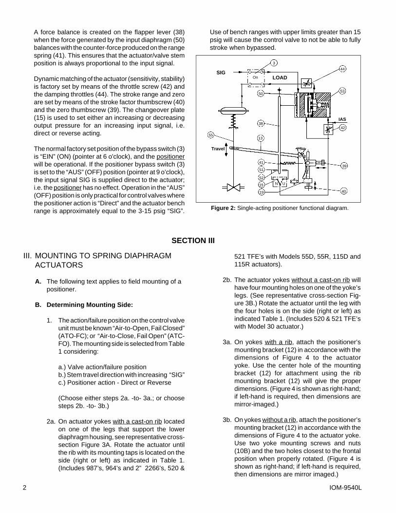
A force balance is created on the flapper lever (38)when the force generated by the input diaphragm (50)balances with the counter-force produced on the rangespring (41). This ensures that the actuator/valve stemposition is always proportional to the input signal.
Dynamic matching of the actuator (sensitivity, stability)is factory set by means of the throttle screw (42) andthe damping throttles (44). The stroke range and zeroare set by means of the stroke factor thumbscrew (40)and the zero thumbscrew (39). The changeover plate(15) is used to set either an increasing or decreasingoutput pressure for an increasing input signal, i.e.direct or reverse acting.
The normal factory set position of the bypass switch (3)is “EIN” (ON) (pointer at 6 o'clock), and the positionerwill be operational. If the positioner bypass switch (3)is set to the “AUS” (OFF) position (pointer at 9 o’clock),the input signal SIG is supplied direct to the actuator;i.e. the positioner has no effect. Operation in the “AUS”(OFF) position is only practical for control valves wherethe positioner action is “Direct” and the actuator benchrange is approximately equal to the 3-15 psig “SIG”.
Use of bench ranges with upper limits greater than 15psig will cause the control valve to not be able to fullystroke when bypassed.
III. MOUNTING TO SPRING DIAPHRAGMACTUATORS
A. The following text applies to field mounting of apositioner.
B. Determining Mounting Side:
1. The action/failure position on the control valveunit must be known “Air-to-Open, Fail Closed”(ATO-FC); or “Air-to-Close, Fail Open” (ATC-FO). The mounting side is selected from Table1 considering:
a.) Valve action/failure positionb.) Stem travel direction with increasing “SIG”c.) Positioner action - Direct or Reverse
(Choose either steps 2a. -to- 3a.; or choosesteps 2b. -to- 3b.)
2a. On actuator yokes with a cast-on rib locatedon one of the legs that support the lowerdiaphragm housing, see representative cross-section Figure 3A. Rotate the actuator untilthe rib with its mounting taps is located on theside (right or left) as indicated in Table 1.(Includes 987’s, 964’s and 2” 2266’s, 520 &
521 TFE’s with Models 55D, 55R, 115D and115R actuators).
2b. The actuator yokes without a cast-on rib willhave four mounting holes on one of the yoke’slegs. (See representative cross-section Fig-ure 3B.) Rotate the actuator until the leg withthe four holes is on the side (right or left) asindicated Table 1. (Includes 520 & 521 TFE’swith Model 30 actuator.)
3a. On yokes with a rib, attach the positioner’smounting bracket (12) in accordance with thedimensions of Figure 4 to the actuatoryoke. Use the center hole of the mountingbracket (12) for attachment using the ribmounting bracket (12) will give the properdimensions. (Figure 4 is shown as right-hand;if left-hand is required, then dimensions aremirror-imaged.)
3b. On yokes without a rib, attach the positioner’smounting bracket (12) in accordance with thedimensions of Figure 4 to the actuator yoke.Use two yoke mounting screws and nuts(10B) and the two holes closest to the frontalposition when properly rotated. (Figure 4 isshown as right-hand; if left-hand is required,then dimensions are mirror imaged.)
SECTION III
Figure 2: Single-acting positioner functional diagram.
Travel
LOADSIG
IAS
3
44
53
42
39
40
41
51
52
15
19
55
On
N U
50
38
13

IOM-9540L 3
CONTROL VALVE POSITIONER PLUG ACTIONCASHCO ACTION/FAIL MOUNTING ACTION CHANGEOVER STEM TRAVEL WITH SIGNAL
PRODUCT POSITION LOCATION PLATE SETTING DIRECTION INCREASING
ATO-FC Right Direct Downwards Opens2"- 2266 to Open
& 964(Non- ATC-FO Left Direct Downwards Closes
Reversible to CloseActuator,
Reversible ATC-FO Right Reverse Downwards OpensTrim) to Close
ATO-FC Left Reverse Downwards Closesto Open
987, 988, ATO-FC Left Direct Upwards Opens988MB, 989, to Open
520, 521,SCV-S, ATC-FO Right Direct Upwards ClosesSCV-30 to Open (Non-
Reversible ATC-FO Left Reverse Upwards OpensTrim, to Open
ReversibleOR Non- ATO-FC Right Reverse Upwards Closes
Reversible to OpenActuator)
Figure 3A
Figure 4
Figure 5A (Model 987)
Figure 3B
TABLE 1
CROSS-SECTION SIDE VIEW
CROSS-SECTION
SIDE VIEW
12
10A 10Bor
2117
BP
13
11
2-1/8"
2-7/8"
N
U
N
UN
U
N
U
N
U
N
UN
U
N
U

IOM-9540L4
4. If the control valve does not have an accessoryplate (AP) installed, the actuator stem must be de-coupled from the valve stem. (Refer to the valve/actuator instructions for de-coupling procedure.)Place accessory plate (AP) as indicated in Fig-ures 5A, 5B or 5C.
5. If it is necessary to re-orient an existing accessoryplate (AP) that is secured to the valve’s stem by ajam nut, loosen the jam nut so that the accessoryplate (AP) is loosened enough that it can be tippedand rotated to the proper frontal position. Re-tighten the accessory plate (AP) jam nut. Attachthe stem feedback carrier bolt (14) to the acces-sory plate (AP) using the Tinnerman nut.
(Note : Above is true for the 987 and 2296 actuators.For Models 30, 55D, 55R, 115D and 115R actuators,separate accessory plates are required for “left” or“right” mounting positions.)
6. Remove the positioner cover (WC). Orient the unitso that the DAMPING & GAIN labels are top/center, and the gauges (1A & 1B) are right side up.
7. Fasten the positioner baseplate (BP) to the mount-ing bracket (12) using the two mounting screws(11) (See Figure 4).
8. With the actuator at zero stroke (“LOAD” = 0 psig;i.e. no air to actuator diaphragm), attach thefeedback lever (13) on the main shaft (17) (Figure4) of the positioner with the feedback carrier bolt(14) located in the feedback lever’s (13) slot. Thecompensating spring (18) must be located abovethe feedback carrier bolt (14) when the unit mount-ing is on the right (See Figure 6A), and below thefeedback carrier bolt (14) when the mounting is onthe left. (See Figure 6B). Hand tighten socket capscrew (21) (Figure 4); DO NOT WRENCHTIGHTEN!
9. Press the stroke factor lever (19) (See Figure 7) ofthe positioner’s internals against the travel stoppin (20) and hold firmly in place. Place the #5 Allenwrench into the head of the socket cap screw (21),and tighten while still holding stroke factor lever(19). Tighten firmly. (A 5 mm, #5 metric Allenwrench should be provided with the unit.)
10. Install tubing fittings with acceptable thread seal-ant and tubing from the unit’s 1/4” NPT (female)“OUTPUT 1” port of the adapter block(AB) up to
Figure 5B: (Model 964 w/left and right mounting positions)
Figure 6A
Figure 6B
Figure 5C: (Model 521 w/Model 30 actuator)
IOM-9540L 5
the connection port of the actuator casing. NOTE-Thread Sealants: If TFE tape is used, make surethat small pieces of tape will not be “pinched off”and enter the pneumatic internals. (Liquid threadsealants are not recommended.)
11. Place temporary fittings and tubing so that thepositioner is able to be supplied with a 20-35 psigair supply to the “SUPPLY AIR” port of the adapterblock (AB). Supply pressure depends upon actua-tor bench range; see Table 2. Using a manualloader, connect a 3-15 psig air source to the“INPUT (3-15 psig) W” port of the adapter block(AB).
12. Stroke the valve thru its full travel by varying theinput signal “SIG” span of 3-15 psig. Observe thefeedback linkage to assure that the linkage doesnot bind and does experience overtravel. At a 9psig signal input, the feedback lever should beapproximately horizontal.
IMPORTANT NOTE: If the feedback lever (13) isturned forcibly against the travel stop pin (20), thestroke factor lever (19) will be released from rigidconnection (unscrews) to the positioner main shaft(17). If this occurs, the feedback lever (13) mustbe loosened, the main shaft (17) must be retight-ened to the stroke factor lever (19) by holding thestroke factor lever (19) firmly against the travelstop pin (20), while turning the main shaft (17) CW(viewed from shaft end) using a screwdriver on themain shaft’s (17) end. Steps 8 thru 11 must berepeated.
13. Leave temporary air sources as installed for finalcalibration, Section V, but turn off the air supply sothat no pressures are induced to the internals.
IV. BASIC ADJUSTMENTS/SETTINGS
A. Required Tools:
The following tools are required for the basicadjustment:
1. Screwdriver2. Open-end wrench - 6 mm3. Feeler gauge 0.6 mm (.024 in)4. (2) test gauges - 30 psig (for 20 psig max
bench range); (1) test gauge - 30 psig and(1) test gauge - 60 psig (for 30 psig max benchrange)
5. Manual loader/airset6. Open-end wrench - 10 mm7. Needle-nose pliers; small8. #5 Allen wrench (5 mm) (provided)
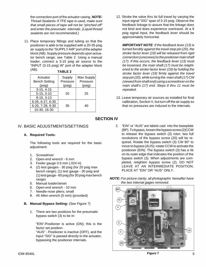
B. Manual Bypass Setting: (See Figure 7)
1. There are two positions for the pneumaticbypass switch (3) to be in:
“EIN”-Positioner is active (ON); this is thefactor set position.“AUS” - Positioner is inactive (OFF), and theinput “SIG" is passed directly to the actuator,bypassing the positioner internals.
2. “EIN” or “AUS” are labels cast into the baseplate(BP). To bypass, loosen the bypass screw (2)CCWto release the bypass switch (3) rotor; two fullrevolutions of the bypass screw (20) will be re-quired. Rotate the bypass switch (3) CW 90° tomove to bypass (AUS); rotate CCW to activate thepositioner (EIN). The bypass switch (3) has a ribon its outer edge that indicates the position of thebypass switch (3). When adjustments are com-pleted, retighten bypass screw (2). DO NOTLEAVE AT AN INTERMEDIATE POSITION;PLACE AT “EIN” OR “AUS” ONLY.
NOTE: For picture clarity, all photographs hereafter havethe two internal gages removed.
SECTION IV
Actuator Supply Max SupplyBench Setting Pressure Pressure
(psig) (psig) (psig)3-15, 4-155-15, 3-10 20 258-15, 3-13
6-26, 6-27, 6-306-20, 7-28, 9-30 35 40
10-30, 16-30
TABLE 2
Figure 7

IOM-9540L6
Applicable Range Spring (41)Valve Split Range Input ProductStroke Input Signal: 3-15 psig Signals: 3-9, 9-15, 3-7, Size - Model
7-11 and 11-15 psigP/N* Color Code P/N* Color Code
7/16" -08000- light yellow -08000- light yellow 1/2"-520 & 521 TFE's1/2" -08000- " -08000- light yellow All sizes 987
9/16" -08000- " -08001- olive green 1" & 1-1/2" 964's5/8" -08000- " -08001- " 1" 520 & 521 TFE's3/4" -08000- " -08001- " 2" 22667/8" -08000- " -08001- " 2" 520 & 521 TFE's
1-1/8" -08001- olive green -08002- light gray 2" & 3" 964's
PART NO. COLOR COILS
lightgray
830-69-5-08002-00 7 -1/4
olivegreen
830-69-5-08001-00 6 -3/4
lightyellow
830-69-5-08000-00 5 -3/4
D. Range Spring Selection:
1. Each positioner unit is supplied with a color-coded range spring (41). Figure 8 shows thesprings; identification is by the number ofcoils. The range spring (41) to be utilized isindicated above in Table 3.
2. To remove/change the range spring (41) seeFigure 9; hold stroke factor lever (19) againstthe travel stop pin (20) and simultaneouslyhold the zero thumbscrew (39). Using needlenose pliers, remove the end of the rangespring (41) hooked to the flapper; then re-move the opposite end from the zero mecha-nism. Reverse the procedure with the new/different range spring (41). Always make surethat the range spring’s (41) coils are closestto the flapper lever (38).
3. After removal/change of the range spring(41), recalibration is required. See Section V.
C. Action Setting:
1. Refer to Table 1 to see the graphical indicatedposition of the changeover plate (15). Theindicator arrow is located on the edge of thebaseplate (BP). There are two positions forthis pneumatic switch to be in:
“N” - Direct action“U” - Reverse action
2. The “N” and “U” are labels cast into thesurface of the changeover plate (15). If neces-sary, to change action loosen CP screw (4) toremoval. Lift the changeover plate (15) and itsCP gasket (16) and replace them to align thelabel with the arrow as desired. Replace andretighten changeover plate screw (4).
V. CALIBRATION/ADJUSTMENTS
A. ZERO AND STROKE Settings : (See Figure 9)
1. After settings of Section IV have been com-pleted, place separate manual loaders to sup-ply the positioner with air (“IAS”) and developa variable 3-15 psig signal (“SIG”) as theinput.
2. If the positioner has an input “SIG” of 3-15, 3-9 or 3-7 (i.e. full stroke is a 15 psig, 9 psig or7 psig “SIG” respectively for REVERSE ac-tion), skip Step 3 following and go to Step 4.
3. If the positioner is split ranged for 9-15 or 11-15 psig “SIG” input (i.e. zero stroke is at a 9psig or 11 psig “SIG” respectively for DIRECTaction; full stroke is at a 9 psig or 11 psig
“SIG” respectively for REVERSE action), thenfollow this procedure:
a. Shutoff supply air (“IAS”, i.e. 0 psig).
b. Release all tension on range spring (41)by turning zero thumbscrew (39) CCW.
c. See Figure 4; loosen screw (21) securingthe feedback lever (13) on the backside ofthe unit to the main shaft (17) using the #5(5 mm) metric Allen wrench provided.Manually move the stroke factor lever(19) away from the tip of the stop pin (20)a distance of approximately 1/4” - 3/8”using some form of spacer; i.e. foldedcardboard, etc. Retighten feedback lever(13) to main shaft (17). Remove the tem-porary 1/4” - 3/8” spacer.
SECTION V
TABLE 3
*Complete Part Number (P/N) is shown in Figure 8. Table 3 indicates the missingnos. of the complete P/N. General P/N = 830-69-5-_ _ _ _ _-00.
Figure 8

IOM-9540L 7
d. Introduce an air supply (“IAS”) to the positioner asrequired by Table 2.
e. Press the flapper lever (38) several times to theleft and right until the flappers are correctly aligned.
f. Set the minimum input “SIG” with the manualloader; i.e. 9 psig for 9-15 psig, 11 psig for 11-15psig.
g. Turn zero thumbscrew (39) CW, increasing ten-sion of range spring (41), until the actuator beginsto move away from its zero (shelf) position. (Ifadjustment does not cause valve response, turnoff air supply (“IAS”) and return to 3.C. above;increase the temporary spacer thickness in incre-ments of 1/8” and repeat steps until the valve doesmove). Care should be taken to assure that thestroke factor lever (19) does not overtravel fromthe starting point to the point where the strokefactor lever (19) will hit the housing cover (WC),before reaching its end position - approximately39° rotation.
h. Induce the maximum input “SIG” with the manualloader; i.e. 15 psig for 9-15 psig or 11-15 psig.
i. Turn the stroke factor thumbscrew (40) CW; thisshortens the valve stroke with respect to the “SIG”change; i.e. less air pressure required to reachvalve’s maximum stroke position. Once valvestem moves with each CW adjustment of thestroke factor thumbscrew (40), reverse to CCWrotation of stroke factor thumbscrew (40) andprecisely adjust up to the maximum stroke posi-tion of the control valve.
j. Repeat Steps e. and h. a minimum of threetimes, as under this adjustment of Steps b.andc. above, the STROKE and ZERO adjust-ments are mutually dependent; i.e. interact-ing.
k. If procedures of Step 3 above have beencompleted, skip Step 4 following, and go tonext paragraph V.B.
4. Press the flapper lever (38) several times to theleft and right until the flappers are correctly aligned.
a. Induce the minimum value of the input signal(“SIG”) using a manual loader. (This corre-sponds to the start of the valve’s stroke.)
b. Turn the zero thumbscrew (39) either CW orCCW until the actuator begins to cause valvestem travel. Precisely adjust to the point wheretravel just begins.
c. Induce the maximum value of the input “SIG”.(This corresponds to the end of the valve’sstroke.)
d. Turn the stroke factor thumbscrew (40) firstCCW until observing the shortening of thevalve’s stroke. Turn the stroke factor thumb-screw (40) CW until the valve travel is pre-cisely at its full stroke.
e. Recheck the ZERO and STROKEsettings.They should be repeatable. Underthis procedure for adjustment, the ZERO andSTROKE calibrations are mutually indepen-dent (i.e. non-interacting, when the feedbacklever (13) and travel stop pin (20) are properlyinstalled and positioned.
B. Setting GAIN: (See Figure 10)
1. Increasing GAIN increases the sensitivity of thepositioner to a change in the input “SIG”. GAIN isnormally factory set when mounted by the factory,and should not require field adjustment.
2. The open loop gain varies with the supply “IAS”pressure, and the values represent linear amplifi-cation. Table 4 is a guide to the gain available foreach range spring (41) utilized:
Figure 9
Supply Pressure Adjustable(psig) Range
20 150:135 125:1
TABLE 4

IOM-9540L8
3. A change in GAIN is normally indicated wheninstability sluggishness shows up at steadystate operating conditions. If the positioneroutput “LOAD” seems to rapidly oscillate (psst-psst-psst-...,) too much gain is present andGAIN setting should be reduced until stabilityis reached. If the positioner output “LOAD”does not react to small changes in the “SIG”,insufficient GAIN may be present; increaseGAIN until instability (psst-psst-psst-...) ispresent, then reduce as described previously.This procedure allows the gain of the controlloop to match the dynamic requirements ofthe control system.
4. Determine whether GAIN should increase ordecrease based on above text. To increaseGAIN, rotate throttle screw (42) CW; to de-crease GAIN, rotate throttle screw (42) CCW.To prevent overadjustment the throttle screw(42) is located within the limiting screw (43).This allows the throttle screw (42) to only beadjustable a total of approximately one revo-lution from maximum to minimum. Thus, GAINshould be adjusted slowly in very small incre-ments.
5. If GAIN is adjusted, ZERO resetting may berequired. Check and use Procedure V.A.
C. Setting DAMPING: (See Figure 10)
1. Increasing DAMPING introduces extra timeconstant to the output “LOAD” of the positioner.DAMPING should be increased/decreased
depending on the time observed for the posi-tioner to respond to a large change in input“SIG” during a non-steady state operatingcondition.
2. DAMPING is factory set, and normallyrequires minimal/no adjustment. However, ifdetermined as required, DAMPING is adjust-able from a minimum - to - maximum ratio of1:2.5. In its normal factory set position, thedamping screw (44) is set approximately flushwith the amplifier housing (53); this position isminimum DAMPING. As the damping screw(44) is screwed CW inwards, DAMPING in-creases. DAMPING may be increased by upto approximately three full revolutions of thedamping screw (44), which will represent maxi-mum DAMPING.
VI. MAINTENANCE
A. Adjustment of the Positioner: (See Figure 11)
1. Component adjustment is only required whenthe positioner has been disassembled orsub-assemblies have been exchanged. Allsettings performed in order to match thepositioner to the actuator are described inSections IV. and V.
2. See Section IV.A. for a list of required tools.
SECTION VI
Figure 11
Figure 10

IOM-9540L 9
3. If adjustments are made with the positionermounted on the control valve, the feedback lever(13) on the main shaft (17) of the positioner mustbe loosened. (See Section III:8-9).
a. Set the changeover plate (15) to “N”.
b. Turn the throttling screw (42) CW to its stops(maximum GAIN).
c. Unhook the range spring (41) from the flapperlever (38).
d. Check that the flappers (52) are aligned con-centrically with the nozzles (51). If necessaryloosen the AMPLIFIER mounting screws onthe rear of the positioner and align the ampli-fier (53) sub-assembly accordingly.
e. Press the flapper lever (38) several timesalternately to the left and right, so that the ball-and-socket mounted flappers (52) are alignedparallel to the nozzles (51).
f. Press the flapper lever (38) to the left. Set theclearance between the right-hand nozzle (51)and the right-hand flapper (52) to 0.6 mm(0.024 in.) with the aid of feeler gauge byturning the hexagonal adjuster (56) with a 6mm wrench. Then secure the nut againstfurther turning using sealing paint.
g. Connect the positioner as shown in the testcircuit in Figure 12. Provide an “IAS” of 60psig.
h. Press the flapper lever (38) to the left. If theoutput does not rise to the level of the supplyair pressure, either leaks are present of theflapper (52) is not correctly aligned (repeate.).
I. Hook the range spring (41) onto the flapperlever (38), and provide a 9 psig input “SIG” toport “Input (3-15) W” using a manual loader.
4. The following procedure must be observed inorder to achieve a no-feedback adjustment of thezero and stroke settings:
a. Press the stroke factor lever (19) against thetravel stop pin (20).
b. Set the stroke factor thumbscrew (40) to ahigh stroke factor (approx. 5/64” before theupper stop).
c. Turn the zero thumbscrew (39) until the out-put pressure is 9 psig and make a note of thisvalue.
d. Set the stroke factor thumbscrew (40) to a lowstroke factor (approx. 5/64 before the lowerstop). The output pressure may not vary bymore than ± 0.003 psig as compared with thesetting described in c. above.
e. In case of excessive deviations the travel stoppin (20) should be adjusted. Whenever thetravel stop pin (20) is adjusted, the settingsdescribed in b. -to- d. should be repeated untilthe deviation is less than ±0.003 psig.
f. Seal the travel stop pin (20) with sealing paint.
5. For mounting see Section III.
6. Return the changeover plate (15) to its originalposition if it was “U”. Re-tighten the feedback (13)lever onto the main shaft (17) of the positioner(See Section III.B.8 & 9.).
B. Cleaning The Throttle Screw: (See Figure 10)
1. Unscrew CCW the limiting screw (43). If you can’tpull it out by hand, unscrew CCW the throttlescrew (42) and remove both by hand.
2. Pull the throttle screw (42) out of the limiting screw(43).
3. Place the throttle screw (42) in a solvent (e.g.benzene) and blow through it carefully. It is best toclean in an ultrasonic solvent bath.
4. Turn the throttle screw (42) in again as far as itgoes CW.
5. Turn the limiting screw (43) in as far as it goes CW;then back it out CCW about half a revolution.
6. Secure the limiting screw (43) with sealing paint.
Figure 12
Test Gauge Test Gauge
MANUALLOADER/AIRSET
IAS
IAS
SIG
3-15 psig
See Table 2for pressurerequired
InputW
Output1 Supply Air
Output2
LOAD
IOM-9540L10
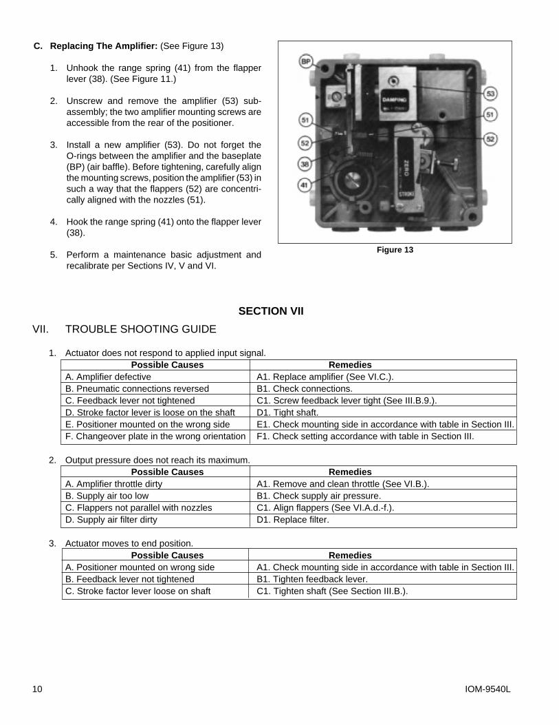
C. Replacing The Amplifier: (See Figure 13)
1. Unhook the range spring (41) from the flapperlever (38). (See Figure 11.)
2. Unscrew and remove the amplifier (53) sub-assembly; the two amplifier mounting screws areaccessible from the rear of the positioner.
3. Install a new amplifier (53). Do not forget theO-rings between the amplifier and the baseplate(BP) (air baffle). Before tightening, carefully alignthe mounting screws, position the amplifier (53) insuch a way that the flappers (52) are concentri-cally aligned with the nozzles (51).
4. Hook the range spring (41) onto the flapper lever(38).
5. Perform a maintenance basic adjustment andrecalibrate per Sections IV, V and VI.
VII. TROUBLE SHOOTING GUIDE
1. Actuator does not respond to applied input signal.Possible Causes Remedies
A. Amplifier defective A1. Replace amplifier (See VI.C.).B. Pneumatic connections reversed B1. Check connections.C. Feedback lever not tightened C1. Screw feedback lever tight (See III.B.9.).D. Stroke factor lever is loose on the shaft D1. Tight shaft.E. Positioner mounted on the wrong side E1. Check mounting side in accordance with table in Section III.F. Changeover plate in the wrong orientation F1. Check setting accordance with table in Section III.
2. Output pressure does not reach its maximum.Possible Causes Remedies
A. Amplifier throttle dirty A1. Remove and clean throttle (See VI.B.).B. Supply air too low B1. Check supply air pressure.C. Flappers not parallel with nozzles C1. Align flappers (See VI.A.d.-f.).D. Supply air filter dirty D1. Replace filter.
3. Actuator moves to end position.Possible Causes Remedies
A. Positioner mounted on wrong side A1. Check mounting side in accordance with table in Section III.B. Feedback lever not tightened B1. Tighten feedback lever.C. Stroke factor lever loose on shaft C1. Tighten shaft (See Section III.B.).
Figure 13
SECTION VII

IOM-9540L 11
4. Unstable behavior; non-steady state in control loop.Possible Causes Remedies
A. Amplification too high A1. Reduce amplification.B. Gland friction on the valve too high B1. Loosen gland packing somewhat or replace.
5. Stroke range cannot be adjusted.Possible Causes Remedies
A. Wrong range spring A1. Replace range spring (See Section IV.D.).B. Positioner does not completely reduce B1. Check supply air pressure. pressure B2. Check amplification.
B3. Adjust clearance between nozzle and flapper.
6. Positioner makes “buzzing” noisePossible Causes Remedies
A. Wrong action setting A1. Check position of the bypass switch and the action.Change as required.
REPAIR PARTS KITS
KIT A: Includes gaskets, O-rings and small parts. Order P/N 295-08-5-07410-00.
KIT B: Replacement pneumatic amplifier. Order P/N 653-75-5-09542-00.

Cashco, Inc.P.O. Box 6Ellsworth, KS 67439-0006PH (785) 472-4461FAX (785) 472-3539E-mail: [email protected] OR
[email protected] in U.S.A. IOM-9540L bt