Model 9139A-PCA Probe Card Adapter Instruction...
45
www.keithley.com Model 9139A-PCA Probe Card Adapter Instruction Manual 9139A-901-01 Rev. E / February 2015 *P9139A90101E* 9139A-901-01 A T ektr onix Company A Greater Measure of Confidence
Transcript of Model 9139A-PCA Probe Card Adapter Instruction...

www.keithley.com
Model 9139A-PCA Probe Card AdapterInstruction Manual9139A-901-01 Rev. E / February 2015
*P9139A90101E*9139A-901-01
A Tektr onix CompanyA Greater Measure of Confidence

Probe Card Adapter
Instruction Manual
© 2015, Keithley Instruments
Cleveland, Ohio, U.S.A.
All rights reserved.
Any unauthorized reproduction, photocopy, or use of the information herein, in whole or in part, without the prior written approval of Keithley Instruments is strictly prohibited.
All Keithley Instruments product names are trademarks or registered trademarks of Keithley Instruments. Other brand names are trademarks or registered trademarks of their respective
holders.
Document number: 9139A-901-01 Rev. E / February 2015
Model 9139A-PCA


Safety precautions The following safety precautions should be observed before using this product and any associated instrumentation. Although some instruments and accessories would normally be used with nonhazardous voltages, there are situations where hazardous conditions may be present.
This product is intended for use by qualified personnel who recognize shock hazards and are familiar with the safety precautions required to avoid possible injury. Read and follow all installation, operation, and maintenance information carefully before using the product. Refer to the user documentation for complete product specifications.
If the product is used in a manner not specified, the protection provided by the product warranty may be impaired.
The types of product users are:
Responsible body is the individual or group responsible for the use and maintenance of equipment, for ensuring that the equipment is operated within its specifications and operating limits, and for ensuring that operators are adequately trained.
Operators use the product for its intended function. They must be trained in electrical safety procedures and proper use of the instrument. They must be protected from electric shock and contact with hazardous live circuits.
Maintenance personnel perform routine procedures on the product to keep it operating properly, for example, setting the line voltage or replacing consumable materials. Maintenance procedures are described in the user documentation. The procedures explicitly state if the operator may perform them. Otherwise, they should be performed only by service personnel.
Service personnel are trained to work on live circuits, perform safe installations, and repair products. Only properly trained service personnel may perform installation and service procedures.
Keithley Instruments products are designed for use with electrical signals that are measurement, control, and data I/O connections, with low transient overvoltages, and must not be directly connected to mains voltage or to voltage sources with high transient overvoltages. Measurement Category II (as referenced in IEC 60664) connections require protection for high transient overvoltages often associated with local AC mains connections. Certain Keithley measuring instruments may be connected to mains. These instruments will be marked as category II or higher.
Unless explicitly allowed in the specifications, operating manual, and instrument labels, do not connect any instrument to mains.
Exercise extreme caution when a shock hazard is present. Lethal voltage may be present on cable connector jacks or test fixtures. The American National Standards Institute (ANSI) states that a shock hazard exists when voltage levels greater than 30 V RMS, 42.4 V peak, or 60 VDC are present. A good safety practice is to expect that hazardous voltage is present in any unknown circuit before measuring.
Operators of this product must be protected from electric shock at all times. The responsible body must ensure that operators are prevented access and/or insulated from every connection point. In some cases, connections must be exposed to potential human contact. Product operators in these circumstances must be trained to protect themselves from the risk of electric shock. If the circuit is capable of operating at or above 1000 V, no conductive part of the circuit may be exposed.
Do not connect switching cards directly to unlimited power circuits. They are intended to be used with impedance-limited sources. NEVER connect switching cards directly to AC mains. When connecting sources to switching cards, install protective devices to limit fault current and voltage to the card.
Before operating an instrument, ensure that the line cord is connected to a properly-grounded power receptacle. Inspect the connecting cables, test leads, and jumpers for possible wear, cracks, or breaks before each use.
When installing equipment where access to the main power cord is restricted, such as rack mounting, a separate main input power disconnect device must be provided in close proximity to the equipment and within easy reach of the operator.
For maximum safety, do not touch the product, test cables, or any other instruments while power is applied to the circuit under test. ALWAYS remove power from the entire test system and discharge any capacitors before: connecting or disconnecting cables or jumpers, installing or removing switching cards, or making internal changes, such as installing or removing jumpers.
Do not touch any object that could provide a current path to the common side of the circuit under test or power line (earth) ground. Always make measurements with dry hands while standing on a dry, insulated surface capable of withstanding the voltage being measured.
For safety, instruments and accessories must be used in accordance with the operating instructions. If the instruments or accessories are used in a manner not specified in the operating instructions, the protection provided by the equipment may be impaired.
Do not exceed the maximum signal levels of the instruments and accessories, as defined in the specifications and operating information, and as shown on the instrument or test fixture panels, or switching card.
When fuses are used in a product, replace with the same type and rating for continued protection against fire hazard.
Chassis connections must only be used as shield connections for measuring circuits, NOT as protective earth (safety ground) connections.
If you are using a test fixture, keep the lid closed while power is applied to the device under test. Safe operation requires the use of a lid interlock.
If a screw is present, connect it to protective earth (safety ground) using the wire recommended in the user documentation.
The symbol on an instrument means caution, risk of danger. The user must refer to the operating instructions located in the user documentation in all cases where the symbol is marked on the instrument.
The symbol on an instrument means caution, risk of electric shock. Use standard safety precautions to avoid personal contact with these voltages.
The symbol on an instrument shows that the surface may be hot. Avoid personal contact to prevent burns.
The symbol indicates a connection terminal to the equipment frame.
If this symbol is on a product, it indicates that mercury is present in the display lamp. Please note that the lamp must be properly disposed of according to federal, state, and local laws.
The WARNING heading in the user documentation explains dangers that might result in personal injury or death. Always read the associated information very carefully before performing the indicated procedure.
The CAUTION heading in the user documentation explains hazards that could damage the instrument. Such damage may invalidate the warranty.
Instrumentation and accessories shall not be connected to humans.
Before performing any maintenance, disconnect the line cord and all test cables.
To maintain protection from electric shock and fire, replacement components in mains circuits — including the power transformer, test leads, and input jacks — must be purchased from Keithley Instruments. Standard fuses with applicable national safety approvals may be used if the rating and type are the same. Other components that are not safety-related may be purchased from other suppliers as long as they are equivalent to the original component (note that selected parts should be purchased only through Keithley Instruments to maintain accuracy and functionality of the product). If you are unsure about the applicability of a replacement component, call a Keithley Instruments office for information.
To clean an instrument, use a damp cloth or mild, water-based cleaner. Clean the exterior of the instrument only. Do not apply cleaner directly to the instrument or allow liquids to enter or spill on the instrument. Products that consist of a circuit board with no case or chassis (e.g., a data acquisition board for installation into a computer) should never require cleaning if handled according to instructions. If the board becomes contaminated and operation is affected, the board should be returned to the factory for proper cleaning/servicing.
Safety precaution revision as of January 2013.

Model 9139A General information ........................................................................... 1-1
Introduction .......................................................................................................................... 1-1
Features ............................................................................................................................... 1-2
Manual addenda .................................................................................................................. 1-2 Safety symbols and terms .................................................................................................... 1-2
Associated documents ......................................................................................................... 1-2
Unpacking and inspection .................................................................................................... 1-3 Inspection for damage ............................................................................................................... 1-3 Shipment contents .................................................................................................................... 1-3 Packing for shipment ................................................................................................................. 1-3
Model 9139A Probe card adapter overview............................................................. 2-1
Introduction .......................................................................................................................... 2-1
Probe card adapter standard components .......................................................................... 2-1
Leakage paths and low current capabilities ......................................................................... 2-2 Mother board characteristics ................................................................................................ 2-3
Probe card configuration ...................................................................................................... 2-3
Probe needle description ..................................................................................................... 2-3
Light shield ........................................................................................................................... 2-3
Options ................................................................................................................................. 2-4
Model 9139A Installation .......................................................................................... 3-1
Introduction .......................................................................................................................... 3-1
Handling precautions ........................................................................................................... 3-2
General installation considerations ...................................................................................... 3-3 Overview ................................................................................................................................... 3-3 Safety ........................................................................................................................................ 3-4 Stack height .............................................................................................................................. 3-4 Cable routing ............................................................................................................................. 3-5 Probe card adapter configuration .............................................................................................. 3-5 Light shield and microscope clearance ..................................................................................... 3-6
Installation procedure ........................................................................................................... 3-6
Probe card removal procedure ............................................................................................ 3-9
Performance verification .................................................................................................... 3-10 Performance Verification Using S530 Diagnotics .................................................................... 3-10
Options ............................................................................................................................... 3-10 Build plate and planarization fixture ........................................................................................ 3-10
Table of Contents
Table of Contents Model 9139A-PCA Probe Card Adapter Instruction Manual
Model 9139A Maintenance ....................................................................................... 4-1
Introduction .......................................................................................................................... 4-1
Mechanical disassembly ...................................................................................................... 4-1
Replacing plug-in type DUT cables ...................................................................................... 4-2
Moving DUT cable connections ........................................................................................... 4-3 Cleaning ............................................................................................................................... 4-4
Replacing pogo pins ............................................................................................................. 4-4
Replacing a pogo pin socket ................................................................................................ 4-5
Replacing vacuum connection ............................................................................................. 4-6
Model 9139A Replacable parts................................................................................. 5-1
Introduction .......................................................................................................................... 5-1
Parts list ............................................................................................................................... 5-1 Probe card adapter ................................................................................................................... 5-1 Blank probe card ....................................................................................................................... 5-1
Ordering information ............................................................................................................ 5-1
Factory service ..................................................................................................................... 5-2 Table 5-1 PCA parts list ............................................................................................................ 5-2 Table 5-2 PCA parts list ............................................................................................................ 5-3 Table 5-3 Probe card retainer and cam assembly ..................................................................... 5-3 Table 5-4 Miscellaneous vacuum control box parts .................................................................. 5-3
Model 9139A Glossary .............................................................................................. 6-1
Glossary ............................................................................................................................... 6-1
Model 9139A Standard probe requirements ........................................................... 7-1
Standard Prober Requirements ........................................................................................... 7-1 Alessi Prober ............................................................................................................................. 7-1 Electroglas 1034 Prober ............................................................................................................ 7-1 Electroglas 2000 Series (EG2001 and EG2010) Prober ........................................................... 7-1 Electroglas 3000 Series (EG3001 and EG3010) Prober ........................................................... 7-1 Electroglas 4060 Prober ............................................................................................................ 7-1 Electroglas 4080 Prober ............................................................................................................ 7-2 Electroglas 4085 Prober ............................................................................................................ 7-2 KLA 1007/1220 Prober .............................................................................................................. 7-2 TEL P-8/P-8XL .......................................................................................................................... 7-2 Pacific Western PW2 Prober ..................................................................................................... 7-2 Pacific Western PW3 Prober ..................................................................................................... 7-3 TAC PR8100 Prober ................................................................................................................. 7-3 Ultraprecision 680 Prober.......................................................................................................... 7-3 Ultraprecision 880 Prober.......................................................................................................... 7-3 Karl Suss Prober ....................................................................................................................... 7-3 TSK A-PM-90A Prober .............................................................................................................. 7-3

Model 9139A-PCA Probe Card Adapter Instruction Manual Table of Contents


In this section:
Introduction .............................................................................. 1-1 Features ................................................................................... 1-2 Manual addenda ...................................................................... 1-2 Safety symbols and terms ........................................................ 1-2 Associated documents ............................................................. 1-2 Unpacking and inspection ........................................................ 1-3
Introduction This section contains general information about the Model 9139A-PCA Probe Card Adapter. The probe card adapter is designed specifically for parametric testing. The advanced design of the probe card adapter provides greater accuracy of parametric tests where a wide range of measurements are needed.
The Model 9139A is a specially designed interface to connect a Keithley Parametric Tester to the device under test (DUT) while maintaining system specifications. Other applications with Keithley switching systems are possible on a custom order basis.
Specific information about installing hardware on the prober is found in the documentation provided by the prober manufacturer.
Information about connections to the Keithley Parametric Test systems is found in the documentation provided with your system.
Section 1
Model 9139A General information

Section 1: Model 9139A General information Model 9139A-PCA Probe Card Adapter Instruction Manual
1-2 9139A-901-01 Rev. E / February 2015
Features Key features of the Model 9139A-PCA Probe Card Adapter include:
• Vacuum lock allows quick exchange of probe cards with accurate and repeatable alignment. • Easy connection of DUT cables to probe card. • Mother board accepts 64 DUT cables; probe card contains 64 fully guarded measure and sense
lines. • Maintains test system specifications to the probe tip. • Preserves full Kelvin connections to probe tip. • Extended guards (reduces capacitance). • DUT cables can be routed vertically or horizontally to the motherboard, supporting many different
probers. • Extends low current capabilities of the Keithley Para\-metric Test system.
Manual addenda Any improvements or changes concerning the probe card adapter or manual will be explained in an addendum included with the unit. Be sure to note these changes and incorporate them into the manual before using or servicing the unit.
Safety symbols and terms Refer to the Safety Precautions (on page 1-1) content for pertinent information regarding safety symbols and all precautions that need to be taken while using the probe card adapter.
Associated documents The following associated documents are not included in this manual. They are included with the Keithley Parametric Test System and are recommended references.
• System installation guide — This guide provides general information about locations of components within the system cabinet. This guide also provides information about installing DUT cables, instrument cables and shorting plugs.
• Matrix manual — This manual provides detailed installation and operation instructions for the system matrix.
• The drawing set of your system — These drawings contain detailed information about the configuration of your system. The drawings show the DUT cable connections. Numbers located next to each DUT connection identify the pin number associated with the DUT connection.

Model 9139A-PCA Probe Card Adapter Instruction Manual Section 1: Model 9139A General information
9139A-901-01 Rev. E / February 2015 1-3
Unpacking and inspection
Inspection for damage
Do not touch high impedance areas of the probe card assembly or the probe card. Touching a high impedance area will cause leakage and problems when performing low current measurements. Also, excessive leakage will cause the probe card adapter to fail system tests.
Carefully unpack your Model 9139A-PCA Probe Card Adapter from its original shipping carton and inspect the card for any obvious signs of physical damage. Report any such damage to the shipping agent immediately. Save the original packing carton for possible future shipment.
Shipment contents The following items are included with every Model 9139A-PCA order:
• Model 9139A-PCA Probe Card Adapter • Model 9139A-VUA Vacuum control box • Unpopulated (blank) probe card (This probe card is used for diagnostics and is installed in the
probe card adapter.) • 15' (6 m) of 1/4" the vacuum hose
Packing for shipment Should it become necessary to return the Model 9139A-PCA for repair, carefully pack the Model 9139A-PCA in its original packing carton (or equivalent) along with a RA (return authorization) number.


In this section:
Introduction .............................................................................. 2-1 Probe card adapter standard components ............................... 2-1 Leakage paths and low current capabilities ............................. 2-2 Mother board characteristics .................................................... 2-3 Probe card configuration .......................................................... 2-3 Probe needle description ......................................................... 2-3 Light shield ............................................................................... 2-3 Options ..................................................................................... 2-4
Introduction This section contains an overview of the Model 9139A-PCA Probe Card Adapter.
Probe card adapter standard components The Probe Card Adapter consists of the following parts (see the next figure):
• prober hardware • probe card adapter assembly consisting of:
appropriate DUT cables strain reliefs and other miscellaneous hardware mother board containing interconnect pins for DUT cable connection pogo pins and retention ring light shield prober ring mother board support plate insulation ring (Teflon) probe card ring vacuum connection
• probe card (without probe pins)
Section 2
Model 9139A Probe card adapter overview
Section 2: Model 9139A Probe card adapter overview Model 9139A-PCA Probe Card Adapter Instruction Manual
2-2 9139A-901-01 Rev. E / February 2015
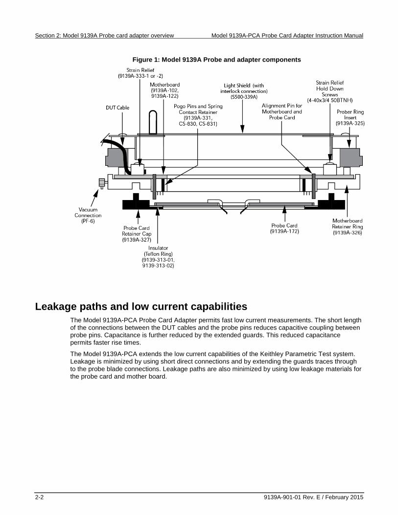
Figure 1: Model 9139A Probe and adapter components
Leakage paths and low current capabilities The Model 9139A-PCA Probe Card Adapter permits fast low current measurements. The short length of the connections between the DUT cables and the probe pins reduces capacitive coupling between probe pins. Capacitance is further reduced by the extended guards. This reduced capacitance permits faster rise times.
The Model 9139A-PCA extends the low current capabilities of the Keithley Parametric Test system. Leakage is minimized by using short direct connections and by extending the guards traces through to the probe blade connections. Leakage paths are also minimized by using low leakage materials for the probe card and mother board.

Model 9139A-PCA Probe Card Adapter Instruction Manual Section 2: Model 9139A Probe card adapter overview
9139A-901-01 Rev. E / February 2015 2-3
Mother board characteristics The mother board is the interface between the DUT cables and the probe card and it accepts 64 DUT cables. It is suspended from the prober mounting hardware. Source, measure, guard, and ground (where appropriate) are terminated for each DUT cable on the mother board. Source, measure, and guard signals are kept separate for each pin and are all carried down to the probe card through spring loaded contacts (pogo pins). Four ground pogo pins take ground down to the probe card. Source and measure lines are guarded on the mother board using state-of-the-art printed circuit board manufacturing techniques. DUT cables can be routed vertically or horizontally to the mother board. Vertical routing is used when the DUT cables are routed above the top platform (head plate) of the prober. Horizontal routing is used when the DUT cables are routed under the top platform of the prober.
Probe card configuration The probe card contains 64 fully guarded measure and sense lines. It contains mounting traces for 64 probe needles. Drilled, plated-through holes are provided for interconnect pins. An unpopulated (blank) probe card is provided with the Probe Card Adapter Assembly. Additional blank probe cards are available through your Keithley sales representative.
To reduce pin-to-pin capacitance, use ceramic blade probes.
Probe needle description Make sure the probe card manufacturer complies with the probe needle specifications required by the Model 9139A (see the next two figures). Note that ceramic needles are recommended (refer to the next note), other types of needles (such as epoxy) may be used as long as they conform to the dimensions contained in the next figure. Refer to the subsequent figure for probe needle mounting information.
Figure 2: Model 9139A Probe needle dimensional specifications
Light shield The light shield covers the opening in the center of the probe card adapter. This blocks ambient light and permits testing under a lights out condition.

Section 2: Model 9139A Probe card adapter overview Model 9139A-PCA Probe Card Adapter Instruction Manual
2-4 9139A-901-01 Rev. E / February 2015
Options The following options are available with the Model 9139A-PCA Probe Card Adapter:
• Build Plate and Planarization fixture — Designed for mounting and adjusting probes on this probe card. The fixture interfaces to the Rucker & Kolls build station #300X and planarization station #425.
Figure 3: Model 9139A Probe needle mounting
In this section:
Introduction .............................................................................. 3-1 Handling precautions ............................................................... 3-2 General installation considerations .......................................... 3-3 Installation procedure ............................................................... 3-6 Probe card removal procedure ................................................. 3-9 Performance verification ........................................................ 3-10 Options ................................................................................... 3-10
Introduction
The installation procedures contained in this manual are intended for use only by qualified service personnel. Do not perform these procedures unless qualified to do so. Failure to observe normal safety precautions could result in personal injury or death.
This section contains information needed for installing the Model 9139A-PCA Probe Card Adapter on your prober. Several paragraphs contain general installation steps. Other paragraphs contain installation steps required for your specific prober. Review the appropriate paragraph(s) before handling or installing the Model 9139A-PCA Probe Card Adapter.
Section 3
Model 9139A Installation

Section 3: Model 9139A Installation Model 9139A-PCA Probe Card Adapter Instruction Manual
3-2 9139A-901-01 Rev. E / February 2015
Handling precautions The Model 9139A Probe Card Adapter is assembled at the factory to provide the highest quality connections possible between the DUT and your system. Use care when handling these parts.
Do not touch high impedance areas of the probe card assembly or the probe card (see next figure). Touching a high impedance area will cause leakage and problems when performing low current measurements. Also, excessive leakage will cause the probe card adapter to fail system tests.
Handle board only by the edges. Use gloves to prevent inadvertent contact with the high impedance areas (see next figure). Avoid bringing the board into contact with sources of contamination. Always confirm that fixtures and handling equipment are clean.
Figure 4: Model 9139A High impedance areas

Model 9139A-PCA Probe Card Adapter Instruction Manual Section 3: Model 9139A Installation
9139A-901-01 Rev. E / February 2015 3-3
General installation considerations
Overview The mechanical architecture of the probe card adapter makes it possible to install the probe card adapter in a wide variety of probers. In general, the architecture consists of a mother board (see the Probe card adapter standard components (on page 2-1) figure) suspended from the prober ring. Spacers inserted between the mother board and prober ring connect the two assemblies. The length of the spacers determines the overall stack height of the probe card assembly. Modification of the mother board assembly is not required when changing the stack height or when replacing the prober ring. The ring insert diameter is changed by replacing the prober ring. The following is a list of the different probers supported by the Model 9139A-PCA Prober Card Adapter:
• Alessi • Electroglas 1034 • Electroglas 2000 Series (EG2001 and EG2010) • Electroglas 3000 Series (EG3001 and EG3010) • Electroglas 4060 • Electroglas 4080 • Electroglas 4085 • KLA 1007 • KLA 1220 • KLA/TEL P-8 • Pacific Western PW2 • Pacific Western PW3 • TAC PR8100 • Ultraprecision 680 • Ultraprecision 880 • Karl Suss • TSK A-PM-90A

Section 3: Model 9139A Installation Model 9139A-PCA Probe Card Adapter Instruction Manual
3-4 9139A-901-01 Rev. E / February 2015
Safety Operator safety from hazardous voltages depends on proper installation. After installation but before energizing the unit, make sure all prober safety shields are properly in place (refer to the manufacturer of your specific prober for prober safety shield information). The light shield contains components to allow for the installation of an interlock switch (such as that provided with a Keithley S500 Series Test System)(see next figure).
Figure 5: Model 9139A PCA light shield
Do not operate the system until it is properly installed and all prober safety shields are in place. Failure to have the complete system properly installed with all safety shields in place could result in personal injury or death.
Stack height The height from the prober’s mounting seat to the surface of the chuck (stack height) is a basic installation consideration (see next figure). This stack height must equal the stack height of the probe card adapter. The stack height of the Keithley probe card adapter can be 1.330 inches (3.378 cm) or 1.492 inches (3.790 cm) depending on the type of prober and on the requirements for cable routing. Refer to Appendix B for prober specific stack height requirements. Installation may require installing mounting hardware onto the prober to ensure that the prober stack height is the same as the probe card adapter stack height (see Cable routing (on page 3-5)).

Model 9139A-PCA Probe Card Adapter Instruction Manual Section 3: Model 9139A Installation
9139A-901-01 Rev. E / February 2015 3-5
Cable routing Cable routing is an important installation consideration. DUT cables can be routed above or below the top plate of the prober. For cable routing above the top plate, the DUT cables exit vertically from the probe card adapter. For cable routing below the top plate, the DUT cables exit horizontally from the probe card adapter.
The DUT cables are routed under the prober ring (of the probe card adapter). In addition, the DUT cables on some probers may exit from the left, right, or from the back of the prober. The cable exit you use depends on the type of prober and how the prober is oriented next to the system. Regardless of how the DUT cables exit from the prober, all the DUT cables must be the same length. A uniform cable length provides uniform electrical characteristics (capacitance and inductance) of the cables. This is important when performing capacitance measurements, or when measuring low level currents (see Installation procedure (on page 3-6) for more information about installing DUT cables).
Figure 6: Model 9139A Stack height
Probe card adapter configuration Confirm that your probe card adapter assembly was configured properly at the factory. Included with your probe card adapter is a copy of your completed Probe Card Adapter Order Guide and a site specific drawing of your probe card adapter.
Confirm that the probe card adapter and the drawing match your requirements as listed on the order guide. Check the following items:
• Check the DUT cables' interconnecting plug(s). Make sure they are the correct type for your system.
• Check that there are the correct number of DUT pins (count the number of cables connected to the mother board).
• Inspect the installation hardware. This hardware is specific to your prober. • Check DUT cable routing. Make sure that DUT cables are assembled correctly to the probe card
adapter. This allows the DUT cables to exit properly from prober after the probe card adapter is installed.

Section 3: Model 9139A Installation Model 9139A-PCA Probe Card Adapter Instruction Manual
3-6 9139A-901-01 Rev. E / February 2015
Light shield and microscope clearance Check the light shield and microscope clearance. Most microscopes are located far enough above the probe card assembly that they do not present clearance problems when the light shield cover is installed. Some microscopes may protrude into the probe ring assembly to the area below the shield plate. This presents clearance problems. If the microscope is mounted on a pivoted arm, move the microscope aside and then install the light shield.
Installation procedure
An installed probe card may contain lethal voltages when a test is in operation. Reset the test equipment to place the PCA (probe card adapter) in a safe state.
Failure to reset the test equipment may cause injury or death due to electrical shock.

Model 9139A-PCA Probe Card Adapter Instruction Manual Section 3: Model 9139A Installation
9139A-901-01 Rev. E / February 2015 3-7
Use the following procedure to install your Model 9139A-PCA Probe Card Adapter:
1. Unpack and inspect Model 9139A-PCA (see Handling precautions (on page 3-2) special handling precautions).
2. Install the probe card adapter in your prober.
The hardware supplied with your probe card adapter assembly varies depending on the type of prober you have (see Overview (on page 3-3) for a list of supported probers).
Appendix B details the specific requirements for a number of standard probers. In some instances, the prober may be modified by the supplier for a particular application. If this is the case, contact Keithley for additional information on prober requirements and available options for the Model 9139A-PCA Probe Card Adapter.
3. Route 1.9 cm O.D. vacuum hose (provided) to probe card adapter out of the way of any moving parts of your prober. Make sure the hose remains clear of any pinch points that could cut off or restrict flow through the vacuum hose. You will need to supply all connections and hardware associated with vacuum hosing, in addition to the vacuum source.
Install the PCA (probe card adapter) to a vacuum control box hose.
• Route a section of vacuum hose from the PCA through the "TO PCA" grommet (on vacuum control box).
• Connect the vacuum control box end of the hose to valve PF-1 (see next figure) and the other end of the hose to the PCA.
Install vacuum supply hose.
• Route the vacuum supply hose from the vacuum source through the "VACUUM IN" grommet (on vacuum control box).
• Connect the vacuum control box end of the hose to check valve PF-5 (see next figure). Make sure vacuum supply is at least 50.8 cm Hg.
Vent the vacuum control box to atmosphere (no connection required).
4. Making sure all power has been removed from the system, connect cables.
• Connect the DUT cables between the probe card assembly and the matrix pin cards of the Parametric Test system. Route the cables to avoid sources of electromagnetic fields. Avoid routing cables near sources of vibration or any other mechanical disturbance.
• Confirm that moving parts of the prober do not contact the cables.
Information regarding the location of connections within your system is found in the configuration drawings for your system. The User's Manual(s) for your systems contains additional information and can be referenced if required.

Section 3: Model 9139A Installation Model 9139A-PCA Probe Card Adapter Instruction Manual
3-8 9139A-901-01 Rev. E / February 2015
Figure 7: Model 9139A Vacuum control box

Model 9139A-PCA Probe Card Adapter Instruction Manual Section 3: Model 9139A Installation
9139A-901-01 Rev. E / February 2015 3-9
5. Install the probe card.
• Turn vacuum control box valve to load/operate position. • Line up probe card pin 1 with pin 1 indicator on the retainer cap (see next figure). • Insert probe card into probe card retainer cap.
Two alignment pins and holes are provided along the perimeter of the probe card. These holes and pins provide for proper orientation of the probe card during installation.
• Align pin 1 of the probe card with pin 1 of the mother board. • Use alignment marking on edge of probe card retainer cap and match to same markings of
mother board support ring. Attach the retainer cap to the mother board ring. Make sure latches secure the probe ring (retainer cap will click into place).
6. Perform probe card continuity test (S400 Series System) to check Kelvin connections from the system matrix to the probe card adapter (see the Options (on page 3-10) topic for more information).
Figure 8: Model 9139A Probe card and probe card retainer
Probe card removal procedure
An installed probe card may contain lethal voltages when a test is in operation. Reset the test equipment to place the PCA (probe card adapter) in a safe state.
Failure to reset the test equipment may cause injury or death due to electrical shock.
1. Run the probe card continuity test program (see the Options (on page 3-10) topic for more information).
2. Turn vacuum control box valve to the unload position. 3. Release the probe card retainer cap latches. 4. Carefully remove probe card and retainer cap from probe card adapter.

Section 3: Model 9139A Installation Model 9139A-PCA Probe Card Adapter Instruction Manual
3-10 9139A-901-01 Rev. E / February 2015
Performance verification A matrix test is run as part of system diagnostics and requires a blank (unpopulated) probe card. Do not run a matrix test after installing each probe card. Run a Matrix Test after the probe card adapter installation to check for leakage, open connections, or shorted connections.
During leakage tests, high voltages are present on the probe card adapter.
It is necessary to install a blank probe card in the probe card assembly to run diagnostics (provided).
A blank probe card is supplied with the probe card adapter. This blank probe card must be retained by the customer. The blank probe card's clean surface provides a known, low leakage test environment. The unmodified Kelvin connections assure accurate continuity tests.
Handling and storage of the blank probe card is important. To permit accurate leakage tests, the probe card must remain unpopulated. The probe card must be stored in a protective container, in a clean, low humidity environment. Handling is important (see Handling precautions (on page 3-2)). When installing this card, handle card by the edges and do not touch the surface of the probe card.
The following list describes the programs to verify performance. For further information about running diagnostics, refer to the software or diagnostics manual for your system.
Performance Verification Using S530 Diagnotics Run the Matrix Tests from S530 diagnostics to verify probe card adapter performance.
Options
Build plate and planarization fixture A build plate and planarization fixture is available through Cerprobe. This fixture permits you to mount and adjust probes on the probe card. The fixture accepts the Keithley probe card. It interfaces to the Rucker & Kolls build station #300X and Planarization station #425.
In this section:
Introduction .............................................................................. 4-1 Mechanical disassembly .......................................................... 4-1 Replacing plug-in type DUT cables .......................................... 4-2 Moving DUT cable connections................................................ 4-3 Cleaning ................................................................................... 4-4 Replacing pogo pins ................................................................. 4-4 Replacing a pogo pin socket .................................................... 4-5 Replacing vacuum connection ................................................. 4-6
Introduction This section describes how to perform maintenance while maintaining the high performance characteristics of the probe card adapter.
A minimum amount of maintenance is required for the mother board and the DUT cables. However, when maintenance is required, it is important to perform maintenance operations correctly. Maintenance items, such as replacing cables, can have a significant impact on the probe card adapter’s performance. When performing maintenance, lubricate all o-rings using Vacuum Goop (from Swagelok™). Make sure to use adequate Vacuum Goop for lubrication, but do not over lubricate o-rings.
For maintenance of the probe pins, refer to documentation provided by the manufacturer of the probe pins.
The system can source high voltages at current levels that can result in personal injury or death. Turn off power to system before performing any maintenance procedure.
Mechanical disassembly Disassembly of the probe card adapter is required when replacing DUT cables or when maintenance is required to the mother board.
When assembling the probe card adapter, use Vacuum Goop (from Swagelok) to coat all o-rings.
Section 4
Model 9139A Maintenance

Section 4: Model 9139A Maintenance Model 9139A-PCA Probe Card Adapter Instruction Manual
4-2 9139A-901-01 Rev. E / February 2015
To disassemble the probe card adapter, use the following procedure:
An installed probe card may contain lethal voltages when a test is in operation. Reset the test equipment to place the PCA (probe card adapter) in a safe state.
Failure to reset the test equipment may cause injury or death due to electrical shock.
If time and space are available, it is possible to disassemble the probe card adapter without disconnecting the DUT cables.
1. Place the PCA in a safe state by resetting the test equipment. 2. Turn the vacuum control box valve to the unload position. 3. Disconnect vacuum hose from the probe card adapter. 4. Disconnect the DUT cables from your system. 5. Remove the probe card adapter assembly from your prober. 6. Remove the light shield assembly (see Probe card adapter standard components (on page 2-1)). 7. Remove the Allen-head screws that secure the cable strain relief, for the cable being replaced or
moved. 8. Remove the probe card from the probe card adapter assembly (see Probe card removal
procedure (on page 3-9)).
Replacing plug-in type DUT cables The DUT cables are pre-assembled with connector pins installed at the factory. Replacement cables with pre-assembled connector pins are available through your Keithley sales office. When you install the replacement cable, note that three sizes of connector pins are used on each DUT cable. The smallest connector pin is installed on the source and measure conductors. A larger size connector pin is installed on the guard conductor. The largest connector pin is installed on the outer shield (ground) conductor.
An installed probe card may contain lethal voltages when a test is in operation. Reset the test equipment to place the PCA (probe card adapter) in a safe state.
Failure to reset the test equipment may cause injury or death due to electrical shock.

Model 9139A-PCA Probe Card Adapter Instruction Manual Section 4: Model 9139A Maintenance
9139A-901-01 Rev. E / February 2015 4-3
To replace a DUT cable, perform the following procedure:
1. Place the PCA in a safe state by resetting the test equipment. 2. Disassemble the probe card adapter assembly (refer to Mechanical disassembly (on page 4-1)). 3. Insert connector pins of cable in sockets in mother board (see next figure). 4. Reassemble probe card adapter.
Figure 9: Model 9139A Replacing plug-in guarded-type DUT cables
Moving DUT cable connections
An installed probe card may contain lethal voltages when a test is in operation. Reset the test equipment to place the PCA (probe card adapter) in a safe state.
Failure to reset the test equipment may cause injury or death due to electrical shock.
Typically prober pin #1 is connected to system pin #1, prober pin #2 is connected to system pin #2, etc. If an application requires different connections, you can connect the prober pins to other system pins.
If you have a Keithley S500 Series system, each DUT cable is independently connected to the matrix. Therefore, to move a DUT connection, you simply unplug the DUT cable from the matrix.
System pin is defined as a node or crossbar in the matrix of your parametric test system.
.

Section 4: Model 9139A Maintenance Model 9139A-PCA Probe Card Adapter Instruction Manual
4-4 9139A-901-01 Rev. E / February 2015
Cleaning Cleaning is important to ensure accurate low current measurements. The cleaning process removes contamination that causes shunt resistance (leakage) between measurement paths.
Contamination can take many forms. Some sources of contamination are:
• Residue remaining after incomplete cleaning. • Residue after using an improper or contaminated cleaning fluids. • Residue from fingerprints (see Handling precautions (on page 3-2) for more information). • Flux from soldering. • Condensation from room conditions which do not meet Keithley specifications.
Observe the following precautions when it is necessary to use solder on a circuit board:
• Use an OA-based (organic activated) flux, and take care not to spread the flux to other areas on the circuit board.
• Remove the flux from the work areas when the repair has been completed. Use pure water along with clean foam-tipped swabs or a clean soft brush to remove the flux.
• Once the flux has been removed, swab only the repaired area with methanol, then blow dry the board with dry nitrogen gas.
• After cleaning, the board should be allowed to dry in a 50°C low-humidity environment for several hours.
Replacing pogo pins
An installed probe card may contain lethal voltages when a test is in operation. Reset the test equipment to place the PCA (probe card adapter) in a safe state.
Failure to reset the test equipment may cause injury or death due to electrical shock.

Model 9139A-PCA Probe Card Adapter Instruction Manual Section 4: Model 9139A Maintenance
9139A-901-01 Rev. E / February 2015 4-5
To replace a pogo pin, use the following procedure:
1. Reset the tester hardware. 2. Remove the probe card from the probe card adapter assembly (see Probe card removal
procedure (on page 3-9)). 3. Remove the defective pogo pin. Grab the pin with a pair of needle-nose pliers. Pull the pin out of
its socket.
The pogo pins are not symmetrical. Damage to the socket may occur if the pogo pins are inserted incorrectly.
4. Locate the rounded end of the replacement pogo pin (see the next figure). Insert the rounded end of the pin into the socket. The double-chisel tip, located on the other end of the pogo pin, must protrude out of the socket. This end of pogo pin contacts a pad located on the probe card.
5. Re-install probe card.
Figure 10: Model 9139A Orientation of pogo pin and socket
Replacing a pogo pin socket If a pogo pin breaks off in a socket or if the pin becomes lodged in a socket, the pogo pin socket can be replaced. To replace a socket, use the following procedure:
An installed probe card may contain lethal voltages when a test is in operation. Reset the test equipment to place the PCA (probe card adapter) in a safe state.
Failure to reset the test equipment may cause injury or death due to electrical shock.

Section 4: Model 9139A Maintenance Model 9139A-PCA Probe Card Adapter Instruction Manual
4-6 9139A-901-01 Rev. E / February 2015
1. Follow the steps in Mechanical disassembly (on page 4-1) to disassemble the probe card adapter.
2. Locate the defective pogo pin or socket assembly. 3. Locate the pad where the defective socket is soldered to the mother board. This pad is on the
probe ring side of the mother board (refer to Probe card adapter standard components (on page 2-1)).
4. Unsolder the socket from the probe ring side (refer to Probe card adapter standard components (on page 2-1)) of the mother board.
Do not apply excessive heat when de-soldering socket. Excessive heat can melt the retention ring of the probe card adapter.
5. Remove the unsoldered pin. Push the end of the socket that protrudes through the mother board. Grab the other end of the socket with a pair of needle-nose pliers. Pull the socket out of its hole in the retention ring.
6. Remove residual solder from hole of solder pad. 7. Insert the small end of the replacement socket into the hole located in the retention ring (see
previous figure). Slide the socket into the hole until the bottom of the socket is flush with the surface of the retention ring (pogo pin not installed in socket).
8. Confirm that the socket is installed properly (see previous figure). The small end of the socket protrudes through the hole on the mother board. The open end of the socket is flush with the surface of the retainer ring.
9. Solder the socket to the pad located on the mother board. 10. Install a pogo pin into the socket. 11. Clean the flux from the solder connection (see Cleaning (on page 4-4) for more information). 12. Re-install the probe card.
Replacing vacuum connection The probe card adapter's vacuum connection can be replaced if damaged. Remove the vacuum connection. Make sure all old sealant is removed from threaded holes on probe card adapter. Lightly apply standard pipe sealant to new vacuum connection and install. Do not overtighten connection.

In this section:
Introduction .............................................................................. 5-1 Parts list ................................................................................... 5-1 Ordering information ................................................................ 5-1 Factory service ......................................................................... 5-2
Introduction This section contains a list of replaceable parts for the Model 9139A-PCA.
Parts list
Probe card adapter Table 5-1 PCA parts list (on page 5-2) contains the part numbers of probe card adapter models 9139A-PCA-01, 9139A-PCA-02, 9139A-PCA-04, and 9139A-PCA-05. Table 5-2 PCA parts list (on page 5-3) contains the part numbers of probe card adapter model 9139A-PCA-03.
Blank probe card For a replacement blank (unpopulated) probe card, order Keithley part number 9139A-172.
Ordering information To place an order, or to obtain information about replacement parts, contact your Keithley representative or see the back cover of this manual for contact information. When ordering parts, be sure to include the following information:
1. Probe card adapter model number 9139A. 2. Adapter serial number. 3. Part description and part number. 4. Circuit designation, if applicable Keithley part number.
Section 5
Model 9139A Replacable parts

Section 5: Model 9139A Replacable parts Model 9139A-PCA Probe Card Adapter Instruction Manual
5-2 9139A-901-01 Rev. E / February 2015
Factory service If the probe card adapter is to be returned to Keithley Instruments for repair, perform the following:
1. Obtain an RA number from Keithley. 2. Carefully pack the probe card adapter in the original packing carton or the equivalent.
Table 5-1 PCA parts list Models 9139A-PCA-01, 9139A-PCA-02, 9139A-PCA-04, and 9139A-PCA-05 parts list
Description Keithley part number .025 PIN 4-40X1/4 PHILLIPS PAN HEAD SCREW (strap to standoff) 4-40X3/4 SOCKET BUTTON HEAD (ring segment mounting) 6-32X1-1/4 SOCKET FLAT HEAD (mother board retainer mounting) 6-32X3/4 PH PAN HD SCR (shield plate mounting) CAP, PROBE CARD RETAINER COVER LIGHT PROBE RING HANDLE, SHIELD INSULATOR, BLACK DECAL INSULATOR, BLACK DECAL O-RING, THERMOBONDED (use Swagelock Vacuuum Goop) O-RING, THERMOBONDED (use Swagelock Vacuuum Goop) PIN, CRIMP BARREL, .040 PIN, CRIMP BARREL, .060 PROBE CARD PROBE, POGO PIN PROBE RING INSERT RECEPTACLE, POGO PIN RETAINER RING RING SEGMENT, CABLE CLAMP (strain relief for Models 9139A-PCA-01 and 9139A-PCA-02) RING SEGMENT, CABLE CLAMP (strain relief for Models 9139A-PCA-04 and 9139A-PCA-05) SHIELD PLATE, PROBE RING SPACER (MODELS 9139A-PCA-01 and 9139A-PCA-04) SPACER (MODELS 9139A-PCA-02 and 9139A-PCA-05) STANDOFF, MOUNTING BLOCK STRAP, PROBE RING SHIELD 10 AWG PVC GREEN/YELLOW 4-40X3/8 SOCKET BUTTON HEAD (mother board to spring contact retainer) LUG LUG MOTHER BOARD RETAINER, SPRING CONTACT SOCKET, .025 SOCKET, .040 SOCKET, .060 WASHER (mother board to spring contact retainer)
CS-835 4-40X1/4PPH 4-40X3/4SOBTNH 6-32X1-1/4SOFHS 6-32X3/4PPH 9139A-327 9139-312 HH-37 9139-313-01 9139-313-02 GA-32 GA-33 CS-836-1 CS-836-2 9139A-172 CS-830 9139A-325A CS-831 9139A-326 9139A-333-1 9139A-333-2 9139A-310 9139A-334-2 9139A-334-1 9139-315 9139-314 SC-99-5 4-40X3/8SOBTNH LU-113 LU-99-6 9139A-102 9139A-331 SO-146-1 SO-146-2 SO-146-3 WA-102-2

Model 9139A-PCA Probe Card Adapter Instruction Manual Section 5: Model 9139A Replacable parts
9139A-901-01 Rev. E / February 2015 5-3
Table 5-2 PCA parts list Model 9139A-PCA-03 parts list
Description Keithley part number .025 PIN 4-40X3/4 SOCKET BUTTON HEAD 4-40X3/8 SOCKET BUTTON HEAD (mother board to spring contact retainer) MOTHER BOARD PIN, CRIMP BARREL, .040 PIN, CRIMP BARREL, .060 PROBE CARD PROBE, POGO PIN RECEPTACLE, POGO PIN RETAINER, SPRING CONTACT RING SEGMENT, CABLE CLAMP SOCKET, .018 PROBE RING CPLB SOCKET, .025 SOCKET, .040 SOCKET, .060 WASHER (mother board to spring contact retainer)
CS-835 4-40X3/4SOBTNH 4-40X3/8SOBTNH 9139A-122 CS-836-1 CS-836-2 9139A-172 CS-830 CS-831 9139A-331 9139A-333-1 SO-147 SO-146-1 SO-146-2 SO-146-3 WA-102-2
Table 5-3 Probe card retainer and cam assembly Quantity Description Keithley part number 1 Retainer Ring 9139A-326 1 Cap, Probe Card Retainer 9139A-327 2 Cam, Retainer 9139A-328 2 Pivot Pin Cam 9139A-329 2 Torsion Spring 9139A-330 1 Ring, Insulator 9139A-332 2 Dowel Pin 9139A-335 2 Dowel Pin Cam 9139A-336 2 Truarc Ring, #45133-14H FA-233-2 1 O-Ring, Thermobonded GA-32 1 O-Ring, Thermobonded GA-33 1 Adapter, Right Angle PF-6 1 4-40 X G PFHUC (handle mount) 4-40XGPFHUC
Table 5-4 Miscellaneous vacuum control box parts Quantity Description Keithley part number 4 Nylon Tie Wrap CC-38-3 4 Tie Mount CC-47 1 Static Shielding Bag PO-13-3 1 Tygon Tubing (order by length) TX-40-1

Section 5: Model 9139A Replacable parts Model 9139A-PCA Probe Card Adapter Instruction Manual
5-4 9139A-901-01 Rev. E / February 2015

In this section:
Glossary ................................................................................... 6-1
Glossary Chuck - The metal platform that holds the wafer during probing.
Head plate (top plate) (ring carrier) - The upper surface of the prober that holds the probe card adapter.
Hypertac™ pin - A type of connector pin used where low contact resistance, long life, and low insertion forces are required.
Interconnect pins - Pins located between the probe card end of the DUT cable and the mother board.
Mother board assembly - The printed circuit board where the DUT cables and pogo pins are soldered.
Mother board support ring - The metal ring located under the mother board.
Pogo pins - The spring loaded contacts that are located between the mother board and the probe card.
Probe blade - A fine wire or contact assembly that provides the electrical connection between the die on the wafer and the probe card.
Probe card - This is the printed circuit board where the probe blades are mounted.
Probe card adapter - The complete probe assembly. This includes the mother board assembly, DUT cables, probe card, and prober specific hardware. The probe card adapter is mounted to the head plate.
Probe card support ring - The retaining ring for the probe card. This is mounted on the bottom side of the Probe Card Adapter and holds the probe card.
Probe needles - The contacts located between the probe card and the pads on the wafer.
Prober specific hardware - Any special hardware that is required to install the probe card adapter into a specific prober.
Ring carrier - Supports the mother board assembly (prober specific).
Stack height (of prober) - The distance between the surface the probe ring mounts on, and the surface of the chuck.
Stack height (of probe card adapter) - This is the distance between the surface where the probe ring rests against the top plate and the tips of the probe blades.
Section 6
Model 9139A Glossary


In this section:
Standard Prober Requirements................................................ 7-1
Standard Prober Requirements
Alessi Prober Stack height 3.378 cm (1.330 inches) Cable Routing Top (only) Cable exit Any direction Ring insert diameter 24.764 cm (9.75 inches) Customer supplied parts
(from Alessi) Adapter ring
Electroglas 1034 Prober Stack height 3.789 cm (1.492 inches) Cable Routing Over top plate of prober (only) Ring insert diameter 24.764 cm (9.75 inches)
Electroglas 2000 Series (EG2001 and EG2010) Prober Stack height 3.789 cm (1.492 inches) Cable Routing Over top plate of prober (only) Ring insert diameter 24.764 cm (9.75 inches)
Electroglas 3000 Series (EG3001 and EG3010) Prober Stack height 3.789 cm (1.492 inches) Cable Routing Over top plate of prober (only) Ring insert diameter 24.764 cm (9.75 inches)
Electroglas 4060 Prober Stack height 3.789 cm (1.492 inches) Cable Routing Over top plate of prober (only) Ring insert diameter 24.764 cm (9.75 inches) Adapter ring part number 254635-001
Section 7
Model 9139A Standard probe requirements
Section 7: Model 9139A Standard probe requirements Model 9139A-PCA Probe Card Adapter Instruction Manual
7-2 9139A-901-01 Rev. E / February 2015
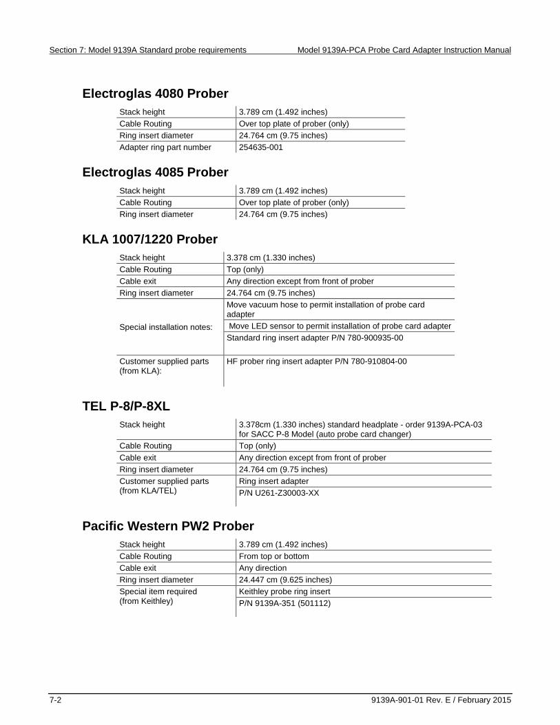
Electroglas 4080 Prober Stack height 3.789 cm (1.492 inches) Cable Routing Over top plate of prober (only) Ring insert diameter 24.764 cm (9.75 inches) Adapter ring part number 254635-001
Electroglas 4085 Prober Stack height 3.789 cm (1.492 inches) Cable Routing Over top plate of prober (only) Ring insert diameter 24.764 cm (9.75 inches)
KLA 1007/1220 Prober Stack height 3.378 cm (1.330 inches) Cable Routing Top (only) Cable exit Any direction except from front of prober Ring insert diameter 24.764 cm (9.75 inches)
Special installation notes:
Move vacuum hose to permit installation of probe card adapter
Move LED sensor to permit installation of probe card adapter Standard ring insert adapter P/N 780-900935-00 Customer supplied parts
(from KLA):
HF prober ring insert adapter P/N 780-910804-00
TEL P-8/P-8XL Stack height 3.378cm (1.330 inches) standard headplate - order 9139A-PCA-03
for SACC P-8 Model (auto probe card changer) Cable Routing Top (only) Cable exit Any direction except from front of prober Ring insert diameter 24.764 cm (9.75 inches) Customer supplied parts
(from KLA/TEL)
Ring insert adapter P/N U261-Z30003-XX
Pacific Western PW2 Prober Stack height 3.789 cm (1.492 inches) Cable Routing From top or bottom Cable exit Any direction Ring insert diameter 24.447 cm (9.625 inches) Special item required
(from Keithley)
Keithley probe ring insert P/N 9139A-351 (501112)
Model 9139A-PCA Probe Card Adapter Instruction Manual Section 7: Model 9139A Standard probe requirements
9139A-901-01 Rev. E / February 2015 7-3
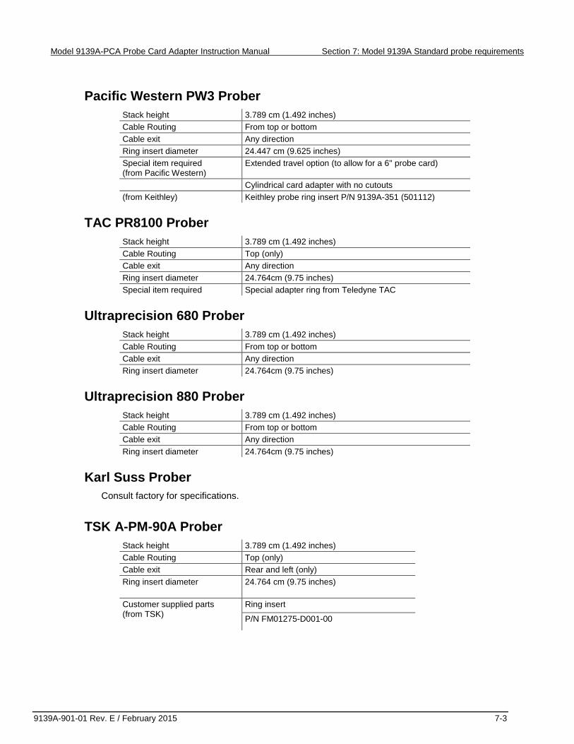
Pacific Western PW3 Prober Stack height 3.789 cm (1.492 inches) Cable Routing From top or bottom Cable exit Any direction Ring insert diameter 24.447 cm (9.625 inches) Special item required
(from Pacific Western) Extended travel option (to allow for a 6" probe card)
Cylindrical card adapter with no cutouts (from Keithley) Keithley probe ring insert P/N 9139A-351 (501112)
TAC PR8100 Prober Stack height 3.789 cm (1.492 inches) Cable Routing Top (only) Cable exit Any direction Ring insert diameter 24.764cm (9.75 inches) Special item required Special adapter ring from Teledyne TAC
Ultraprecision 680 Prober Stack height 3.789 cm (1.492 inches) Cable Routing From top or bottom Cable exit Any direction Ring insert diameter 24.764cm (9.75 inches)
Ultraprecision 880 Prober Stack height 3.789 cm (1.492 inches) Cable Routing From top or bottom Cable exit Any direction Ring insert diameter 24.764cm (9.75 inches)
Karl Suss Prober Consult factory for specifications.
TSK A-PM-90A Prober Stack height 3.789 cm (1.492 inches) Cable Routing Top (only) Cable exit Rear and left (only)
Ring insert diameter 24.764 cm (9.75 inches)
Customer supplied parts (from TSK)
Ring insert
P/N FM01275-D001-00


No index entries found.
Index

Specifications are subject to change without notice.All Keithley trademarks and trade names are the property of Keithley Instruments.
All other trademarks and trade names are the property of their respective companies.
Keithley InstrumentsCorporate Headquarters • 28775 Aurora Road • Cleveland, Ohio 44139 • 440-248-0400 • Fax: 440-248-6168 • 1-800-935-5595 • www.keithley.com
8/14
A Greater Measure of Conf idence