Model 6X00 Preliminary Service Manual - ELHVB · TV Output ... Panasonic JU -226A03F ... This...
107
Model 6X00 Preliminary Service Manual November 1996
Transcript of Model 6X00 Preliminary Service Manual - ELHVB · TV Output ... Panasonic JU -226A03F ... This...

Model 6X00 Preliminary Service Manual November 1996

Notice Updating or revising this manual or making any changes to the information herein will be initiated when the company deems it necessary. The company reserves the right to take the above-mentioned actions and is under no obligation to notify any person of such actions in advance or afterwards. 1996
Trademarks MS-DOS, Microsoft Windows, and Microsoft Mouse are registered trademarks of Microsoft Corporation. IBM PC, OS/2, PS/2, EGA, and VGA are registered trademarks of International Business Machines, Inc. Intel, Pentium are trademarks of Intel Corporation. SystemSoft is a registered trademark of SystemSoft Corp. Sound Blaster Pro is a trademark of Creative Labs, Inc. Duracell is a registered trademark of Duracell Inc. Photo CD is a trademark of Eastman Kodak Company. Other brand and product names are trademarks and/or registered trademarks of their respective companies.

2
Table of Content
Chapter 1: Introduction Overview ..................................................................................................................1 Specifications.............................................................................................................2 LED Indicators................................................................................................3 Power Switch Button......................................................................................3 Microphone 3 System Status LCD Bar ................................................................................4 Top-Front View ...............................................................................................6 LCD Panel..........................................................................................6 System Status LCD Bar ....................................................................6 Dual Stereo Speakers........................................................................6 Trackpad Pointing Device..................................................................6 Windows 95 Keyboard.......................................................................6 Right View ....................................................................................................8 Right-Side Stand................................................................................8 Microphone-in Jack............................................................................8 Line-in Jack........................................................................................8 Headphone Jack.................................................................................8 Infrared...............................................................................................8 PC Card Type III Expansion Slot........................................................8 CD-ROM Drive...................................................................................8 Ventilation ...........................................................................................8 Rear View.......................................................................................................10 DC-in Socket......................................................................................10 Serial Port...........................................................................................10 Expansion Port...................................................................................10 RCA Jack ...........................................................................................10 External Monitor (CRT) Port...............................................................10 MIDI/Game Port..................................................................................10 Parallel Port........................................................................................10 External Keyboard or PS/2 Mouse Port.............................................10 Left View ......................................................................................................12 Left-Side Stand...................................................................................12 Battery Latch......................................................................................12 PC Card Type II Expansion Slot.........................................................12 2.5” Hard Disk Drive...........................................................................12 3.5” Floppy Disk Drive........................................................................12 Internal Battery Pack..........................................................................12 Power.........................................................................................................................14 AC Power .......................................................................................................14 Internal Battery Power....................................................................................15 Duracell Smart Battery at Retails ......................................................16 Second Battery Power (Option).....................................................................17 Duracell Smart Battery at Retails ......................................................18 Operation ..................................................................................................................19 Hardware Configuration.................................................................................19
3
CPU ...................................................................................................19 Speed of CPU........................................................................19 Power of CPU........................................................................19 MPEG Accelerator Card (Option) ......................................................19 RAM Configuration.............................................................................21 TV Output...........................................................................................22 The Keyboard.................................................................................................24 System Function Key.........................................................................24 Cursor Control Keys ..........................................................................24 Embedded Numeric Keypad.............................................................25 Hot Keys.............................................................................................26 Expanded Display Mode.........................................................26 Display Type...........................................................................26 Contrast Control.....................................................................26 Brightness Control .................................................................26 Volume Control ......................................................................26 Contrast/Brightness Saved....................................................26 Suspend Mode .......................................................................26 New Keys for Windows 95 ................................................................27 Application Key.......................................................................27 Windows Keys .......................................................................27 Storage Disks 28 3.5” Floppy Drive................................................................................29 2.5” Hard Disk Drive...........................................................................31 5.25” CD-ROM Drive.........................................................................33 PC Cards Slots ..........................................................................................................34 LCD Panel..................................................................................................................36 Power Management...................................................................................................37 Standby Mode.................................................................................................37 Suspend Mode ...............................................................................................37 Suspend to Memory...........................................................................37 Suspend to Disk.................................................................................37 System Resume............................................................................................38 Resume from Suspend-to-Memory Mode.........................................38 Resume from Suspend-to-Disk Mode...............................................38 Advanced Power Management..................................................................................39
4
Chapter 2: Utilities Overview....................................................................................................................41 Power On Self Test (POST).....................................................................................41 POST Messages - Normal operation ............................................................42 POST Messages - Error Detected ................................................................43 System Configuration Utility (SCU)............................................................................44 Invoking the System Configuration Utility.......................................................44 Working with the Menu Bar of the SCU.........................................................45 Working with the Pull-Down Menu of the SCU..............................................45 Features of the System Configuration Utility.................................................46 System Menu.....................................................................................46 Devices Menu.....................................................................................47 Power Menu .......................................................................................49 Exit Menu............................................................................................51 Power On Self Test Definitions .................................................................................52 Debug Codes for PnP BIOS......................................................................................53 Debug Codes for PCI BIOS.......................................................................................53 Error Codes Returned by APM Sub-functions...........................................................54

5
Chapter 3: Technical View Overview....................................................................................................................55 System Block Diagram ..............................................................................................56 Chips ..........................................................................................................................57 SiS5101 PCI Cache memory Controller .......................................................58 SiS5102 PCI Local Data Buffer......................................................................59 SiS5103 System I/O & PMU ..........................................................................60 SMC FDC37C669FR I/O FDD Controller with IR..........................................62 Omega 82C094 PCMCIA Host Adapter Controller........................................64 ESS ES1788 AudioDrive................................................................................65 ESS ES690....................................................................................................66 ESS ES981 Wavetable Sample Set ROM....................................................67 Trident Cyber9385 Flat Panel Controller........................................................68 Standard Video Modes .......................................................................69 Extended Video Modes.......................................................................70 Video Mode Cross Reference............................................................72 Accessories ...............................................................................................................73 Battery............................................................................................................73 Toshiba Ni-MH Rechargeable Battery................................................73 CD-ROM........................................................................................................74 TEAC CD-46E-900 ............................................................................74 TEAC CD-36E-900 ............................................................................75 TEAC CD-38E-900 ............................................................................76 3.5” Floppy Disk Drive....................................................................................77 Panasonic JU-226A03F.....................................................................77 TEAC FD-04HF-1300.........................................................................78 LCD Panel......................................................................................................79 Sanyo LM-JA53-22NTK 12.1” DSTN..................................................79 Samsung LT104S4-151 10.4” TFT....................................................80 NEC NL8060AC26-04 10.4” TFT .......................................................81 Hosiden HLD1201-0151XX 12.1” TFT ...............................................82 Samsung LT121S1-103 12.1” TFT....................................................83 NEC NL8060BC31-01 12.1” TFT.......................................................84
Chapter 4: Parts List & Circuit Diagram Parts List ....................................................................................................................85 Top Case & Assemblies................................................................................86 Bottom Case & Assemblies ..........................................................................88 10.4” Display Panel & Assemblies ................................................................90 12.1” Display Panel & Assemblies ................................................................92 CD-ROM........................................................................................................94 FDD................................................................................................................95 HDD................................................................................................................96 Battery Pack...................................................................................................97 Circuit Diagrams........................................................................................................98

1
Chapter 1: Introduction Overview The Notebook Computer has many advanced features to help you with your computing work. This chapter describes each of the Notebook Computer’s hardware features in detail and shows you how to use them. It covers:
: Specifications.
: The LED Indicators.
: Button.
: System Status LCD Bar.
: Input/Output.
: Power.
: Hardware Configuration.
: The keyboard.
: The Storage Disks.
: The PC Card Slots.
: The LCD Panel.
: Power Management.
2
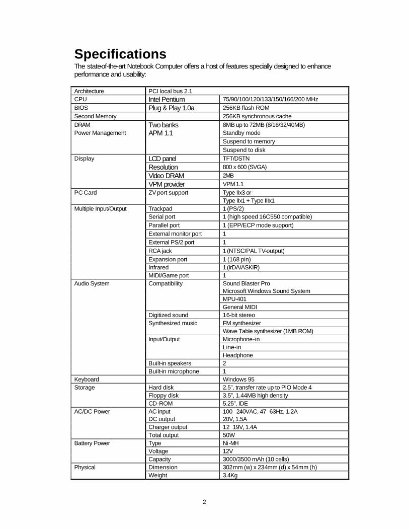
Specifications The state-of-the-art Notebook Computer offers a host of features specially designed to enhance performance and usability: Architecture PCI local bus 2.1 CPU Intel Pentium 75/90/100/120/133/150/166/200 MHz BIOS Plug & Play 1.0a 256KB flash ROM Second Memory 256KB synchronous cache DRAM Two banks 8MB up to 72MB (8/16/32/40MB) Power Management APM 1.1 Standby mode Suspend to memory
Suspend to disk Display LCD panel TFT/DSTN Resolution 800 x 600 (SVGA) Video DRAM 2MB VPM provider VPM 1.1 PC Card ZV-port support Type IIx3 or Type IIx1 + Type IIIx1 Multiple Input/Output Trackpad 1 (PS/2) Serial port 1 (high speed 16C550 compatible)
Parallel port 1 (EPP/ECP mode support)
External monitor port 1
External PS/2 port 1
RCA jack 1 (NTSC/PAL TV-output) Expansion port 1 (168 pin) Infrared 1 (IrDA/ASKIR) MIDI/Game port 1 Audio System Compatibility Sound Blaster Pro Microsoft Windows Sound System MPU-401 General MIDI Digitized sound 16-bit stereo Synthesized music FM synthesizer Wave Table synthesizer (1MB ROM) Input/Output Microphone-in Line-in Headphone Built-in speakers 2 Built-in microphone 1 Keyboard Windows 95 Storage Hard disk 2.5”, transfer rate up to PIO Mode 4 Floppy disk 3.5”, 1.44MB high density CD-ROM 5.25”, IDE AC/DC Power AC input 100∼240VAC, 47∼63Hz, 1.2A DC output 20V, 1.5A Charger output 12∼19V, 1.4A Total output 50W Battery Power Type Ni -MH Voltage 12V Capacity 3000/3500 mAh (10 cells) Physical Dimension 302mm (w) x 234mm (d) x 54mm (h) Weight 3.4Kg

3
LED Indicators Two LED indicators are integrated to alert you of the system’s power status.
Power Switch Button
Microphone
Color of Light Status Green System power on (either by AC or by battery) Red Battery in charge Orange Battery in charge when system power on
Color of Light Status Green Internal battery fully charged Red Second battery fully charged Orange Both batteries fully charged
This button is used either to turn the system on or to turn it off.
This is a built-in input device for audio system.
4
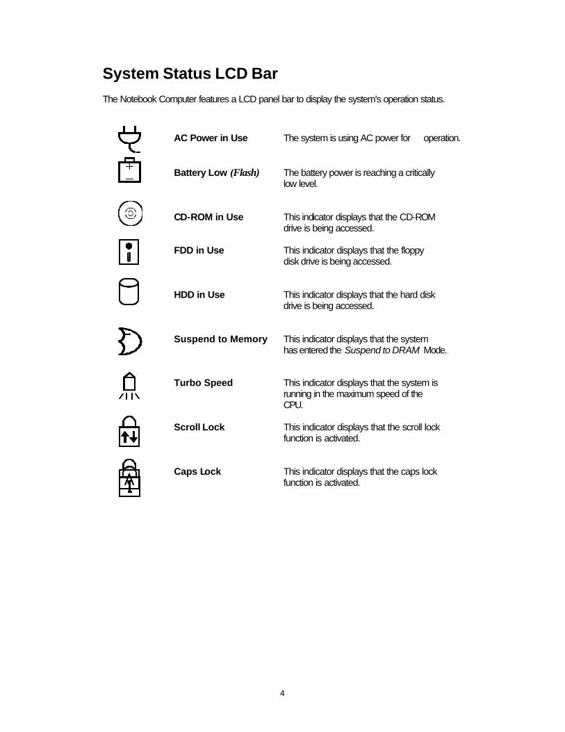
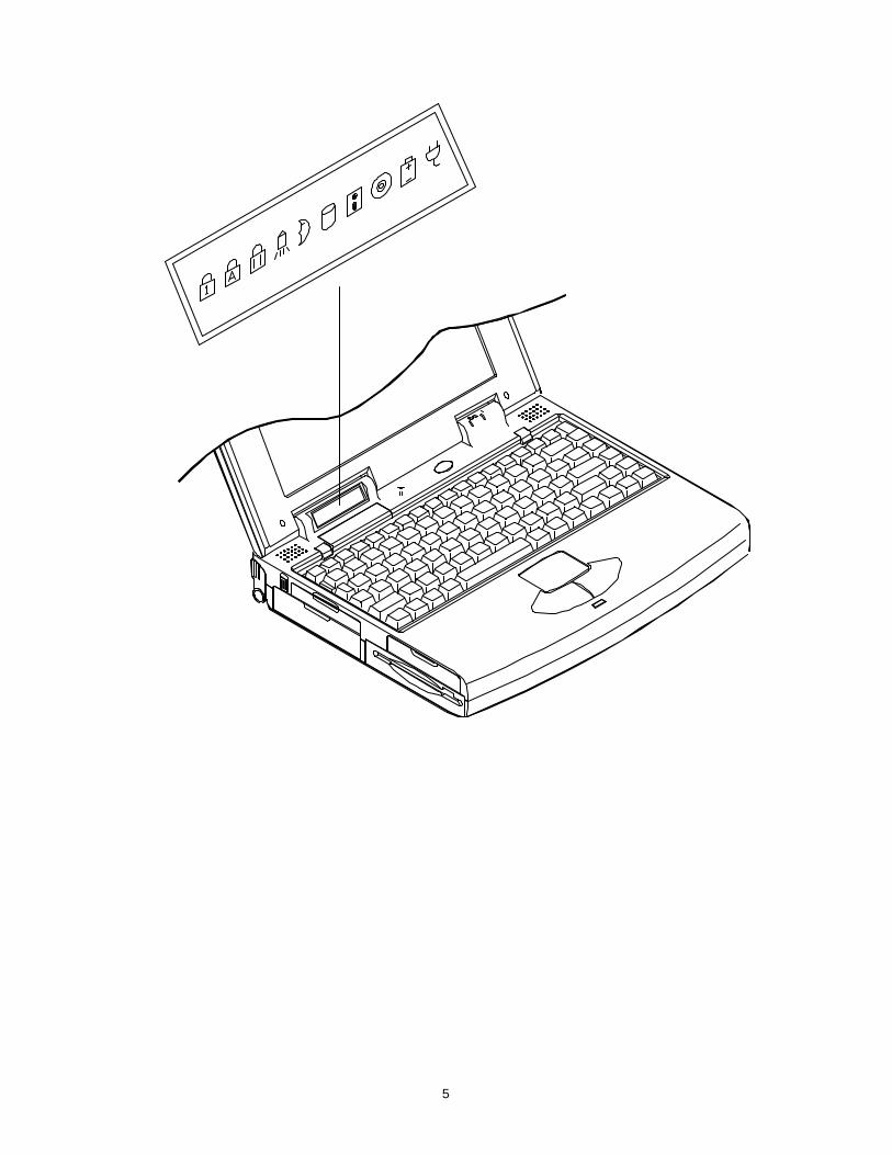
System Status LCD Bar The Notebook Computer features a LCD panel bar to display the system’s operation status.
AC Power in Use The system is using AC power for operation. Battery Low (Flash) The battery power is reaching a critically low level. CD-ROM in Use This indicator displays that the CD-ROM drive is being accessed. FDD in Use This indicator displays that the floppy disk drive is being accessed. HDD in Use This indicator displays that the hard disk drive is being accessed. Suspend to Memory This indicator displays that the system has entered the Suspend to DRAM Mode. Turbo Speed This indicator displays that the system is running in the maximum speed of the CPU. Scroll Lock This indicator displays that the scroll lock function is activated. Caps Lock This indicator displays that the caps lock function is activated.
5
6
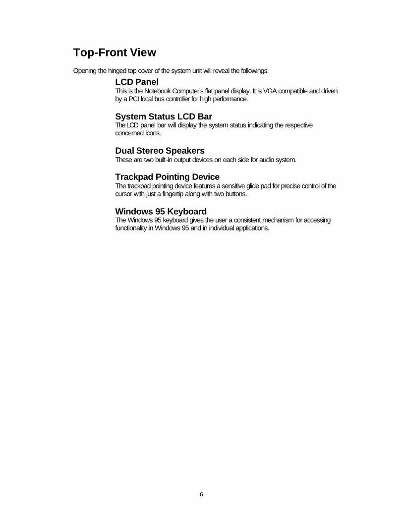
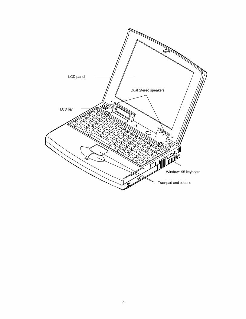
Top-Front View Opening the hinged top cover of the system unit will reveal the followings:
LCD Panel This is the Notebook Computer’s flat panel display. It is VGA compatible and driven by a PCI local bus controller for high performance.
System Status LCD Bar The LCD panel bar will display the system status indicating the respective concerned icons.
Dual Stereo Speakers These are two built-in output devices on each side for audio system. Trackpad Pointing Device The trackpad pointing device features a sensitive glide pad for precise control of the cursor with just a fingertip along with two buttons.
Windows 95 Keyboard The Windows 95 keyboard gives the user a consistent mechanism for accessing functionality in Windows 95 and in individual applications.
7
LCD panel
Dual Stereo speakers
LCD bar
Trackpad and buttons
Windows 95 keyboard
8
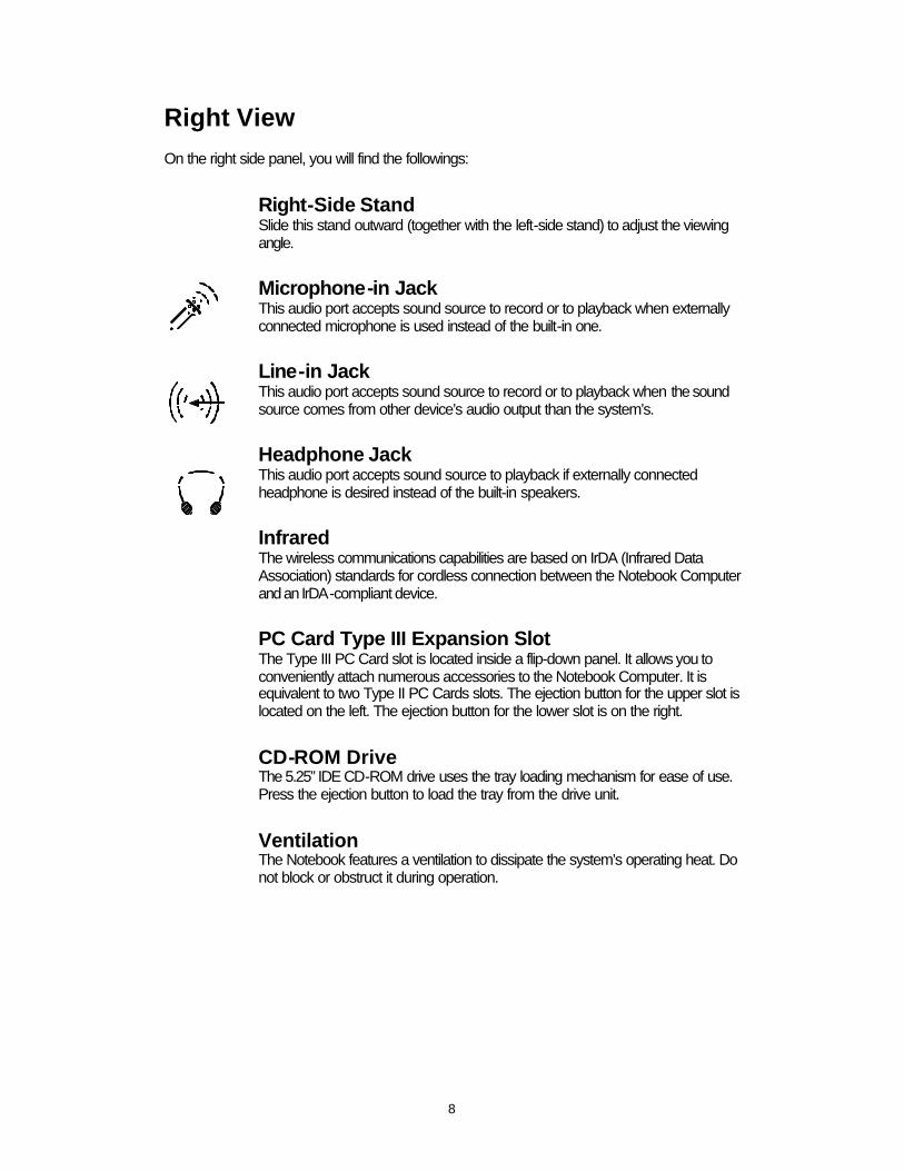
Right View On the right side panel, you will find the followings:
Right-Side Stand Slide this stand outward (together with the left-side stand) to adjust the viewing angle. Microphone-in Jack This audio port accepts sound source to record or to playback when externally connected microphone is used instead of the built-in one. Line-in Jack This audio port accepts sound source to record or to playback when the sound source comes from other device’s audio output than the system’s. Headphone Jack This audio port accepts sound source to playback if externally connected headphone is desired instead of the built-in speakers. Infrared The wireless communications capabilities are based on IrDA (Infrared Data Association) standards for cordless connection between the Notebook Computer and an IrDA-compliant device. PC Card Type III Expansion Slot The Type III PC Card slot is located inside a flip-down panel. It allows you to conveniently attach numerous accessories to the Notebook Computer. It is equivalent to two Type II PC Cards slots. The ejection button for the upper slot is located on the left. The ejection button for the lower slot is on the right.
CD-ROM Drive The 5.25” IDE CD-ROM drive uses the tray loading mechanism for ease of use. Press the ejection button to load the tray from the drive unit.
Ventilation The Notebook features a ventilation to dissipate the system’s operating heat. Do not block or obstruct it during operation.

9
Right-side stand
Microphone-in Line-in Headphone Infrared PC card Type III
CD-ROM drive Ventilation
10
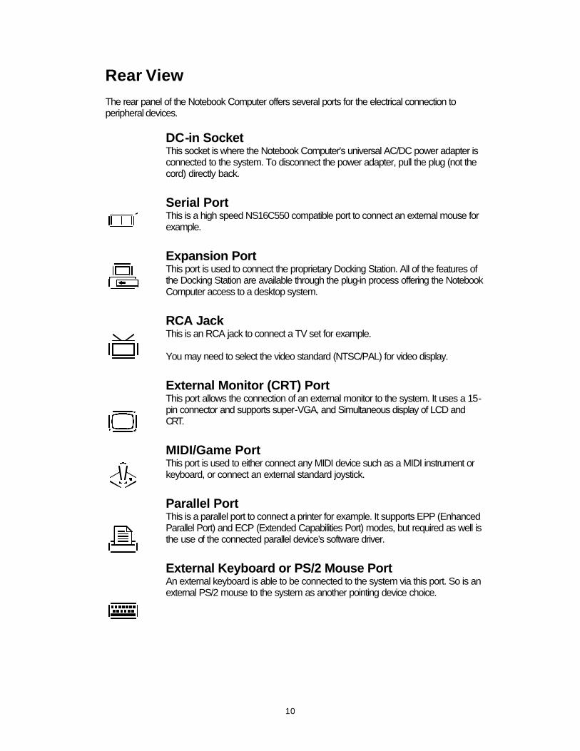
Rear View The rear panel of the Notebook Computer offers several ports for the electrical connection to peripheral devices.
DC-in Socket This socket is where the Notebook Computer’s universal AC/DC power adapter is connected to the system. To disconnect the power adapter, pull the plug (not the cord) directly back.
Serial Port This is a high speed NS16C550 compatible port to connect an external mouse for example.
Expansion Port This port is used to connect the proprietary Docking Station. All of the features of the Docking Station are available through the plug-in process offering the Notebook Computer access to a desktop system.
RCA Jack This is an RCA jack to connect a TV set for example. You may need to select the video standard (NTSC/PAL) for video display.
External Monitor (CRT) Port This port allows the connection of an external monitor to the system. It uses a 15-pin connector and supports super-VGA, and Simultaneous display of LCD and CRT.
MIDI/Game Port This port is used to either connect any MIDI device such as a MIDI instrument or keyboard, or connect an external standard joystick.
Parallel Port This is a parallel port to connect a printer for example. It supports EPP (Enhanced Parallel Port) and ECP (Extended Capabilities Port) modes, but required as well is the use of the connected parallel device’s software driver.
External Keyboard or PS/2 Mouse Port An external keyboard is able to be connected to the system via this port. So is an external PS/2 mouse to the system as another pointing device choice.

11
DC-in socket
Serial port
Expansion port
RCA jack
CRT port
MIDI/Game port
Parallel port
PS/2 port
12
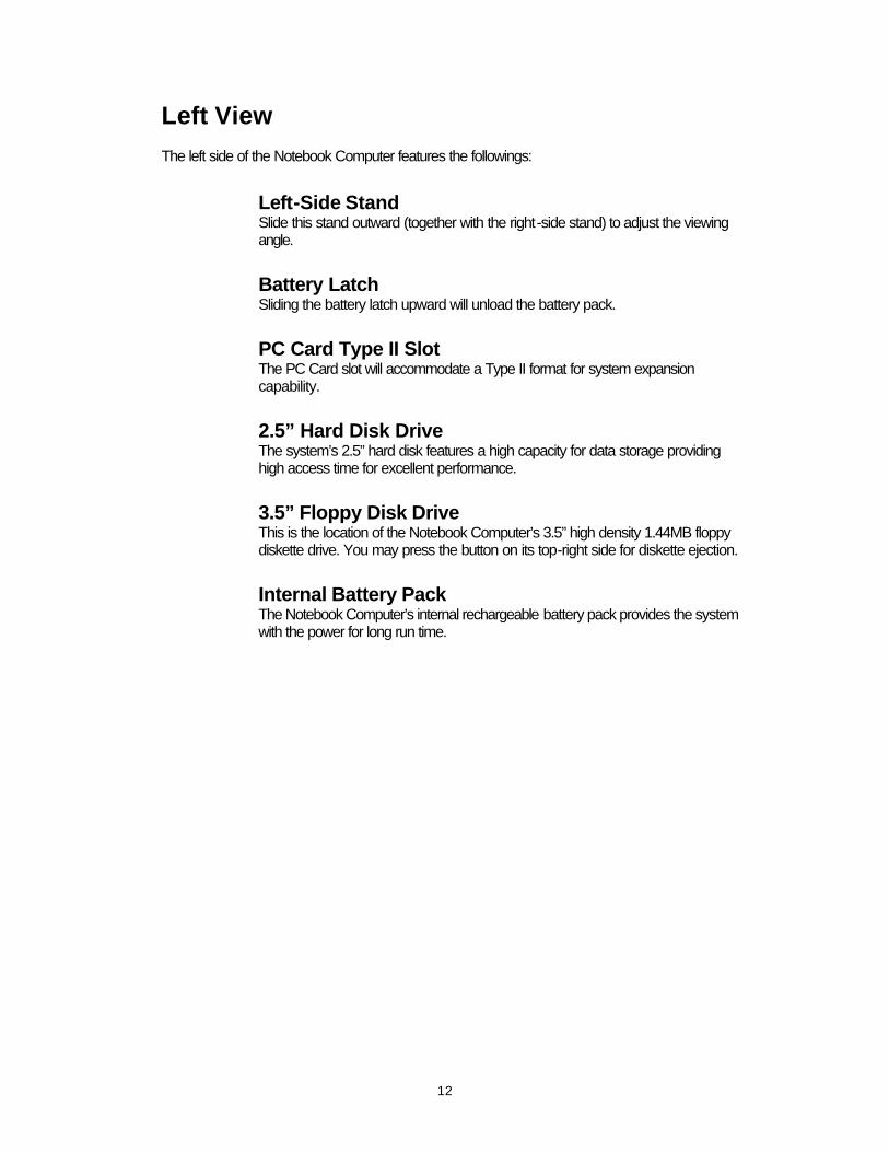
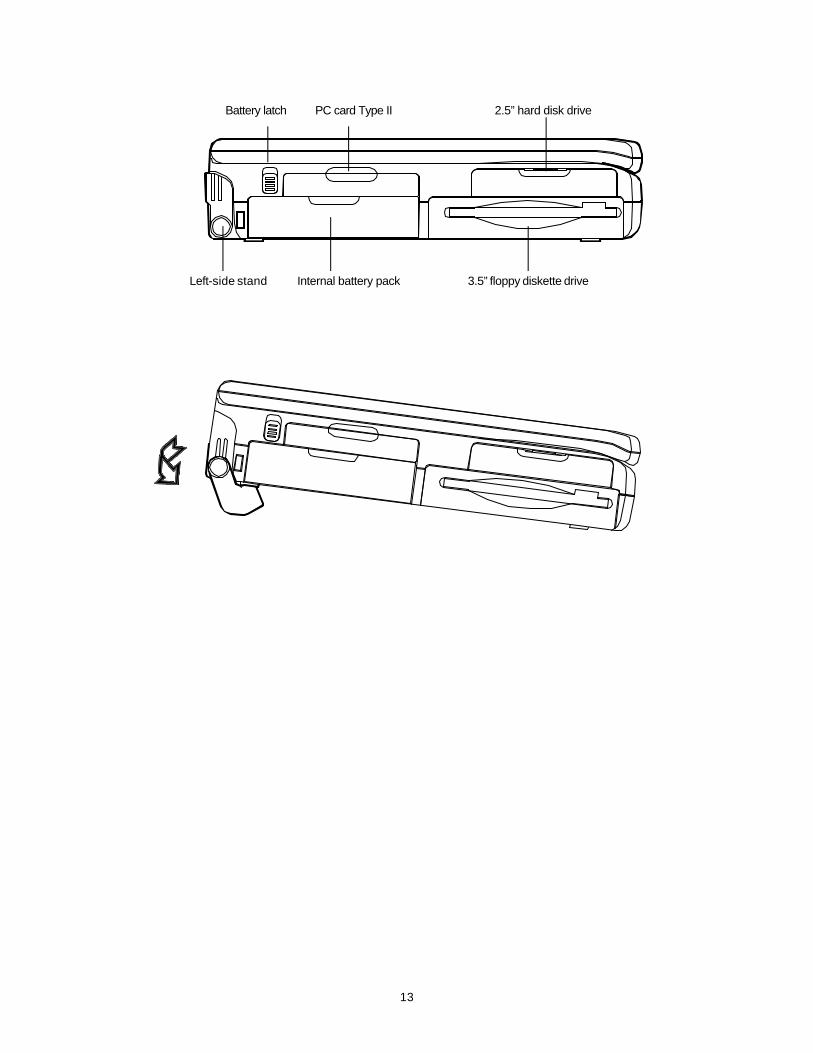
Left View The left side of the Notebook Computer features the followings:
Left-Side Stand Slide this stand outward (together with the right-side stand) to adjust the viewing angle. Battery Latch Sliding the battery latch upward will unload the battery pack. PC Card Type II Slot The PC Card slot will accommodate a Type II format for system expansion capability. 2.5” Hard Disk Drive The system’s 2.5” hard disk features a high capacity for data storage providing high access time for excellent performance. 3.5” Floppy Disk Drive This is the location of the Notebook Computer’s 3.5” high density 1.44MB floppy diskette drive. You may press the button on its top-right side for diskette ejection. Internal Battery Pack The Notebook Computer’s internal rechargeable battery pack provides the system with the power for long run time.
13
Left-side stand Internal battery pack 3.5” floppy diskette drive
Battery latch PC card Type II 2.5” hard disk drive
14
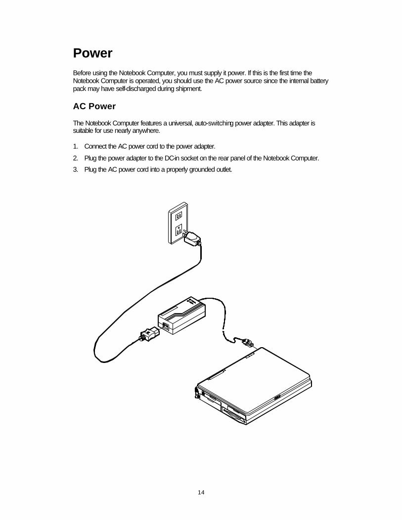
Power Before using the Notebook Computer, you must supply it power. If this is the first time the Notebook Computer is operated, you should use the AC power source since the internal battery pack may have self-discharged during shipment.
AC Power The Notebook Computer features a universal, auto-switching power adapter. This adapter is suitable for use nearly anywhere. 1. Connect the AC power cord to the power adapter.
2. Plug the power adapter to the DC-in socket on the rear panel of the Notebook Computer.
3. Plug the AC power cord into a properly grounded outlet.

15
Internal Battery Power The Notebook Computer is equipped with an internal, rechargeable battery pack which provides continuous portable operation. Proper care is required for optimum performance:
• Do not attempt to disassemble the battery under any circumstances. • The battery may explode if exposed to fire or high temperatures. • Avoid short circuit the battery by the metal terminals (+, -).
16
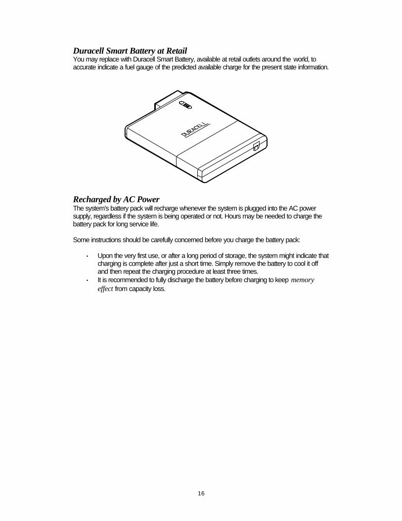
Duracell Smart Battery at Retail You may replace with Duracell Smart Battery, available at retail outlets around the world, to accurate indicate a fuel gauge of the predicted available charge for the present state information.
Recharged by AC Power The system’s battery pack will recharge whenever the system is plugged into the AC power supply, regardless if the system is being operated or not. Hours may be needed to charge the battery pack for long service life. Some instructions should be carefully concerned before you charge the battery pack:
• Upon the very first use, or after a long period of storage, the system might indicate that charging is complete after just a short time. Simply remove the battery to cool it off and then repeat the charging procedure at least three times.
• It is recommended to fully discharge the battery before charging to keep memory effect from capacity loss.

17
Second Battery Power (Option) The Second Battery comes designed, in addition to the system’s internal one, to prolong the battery life for the unit’s portable use. You may need to replace the floppy disk out of the 3.5” drive bay with the Second Battery pack for longer power life.
Second battery pack
3.5” floppy disk
18
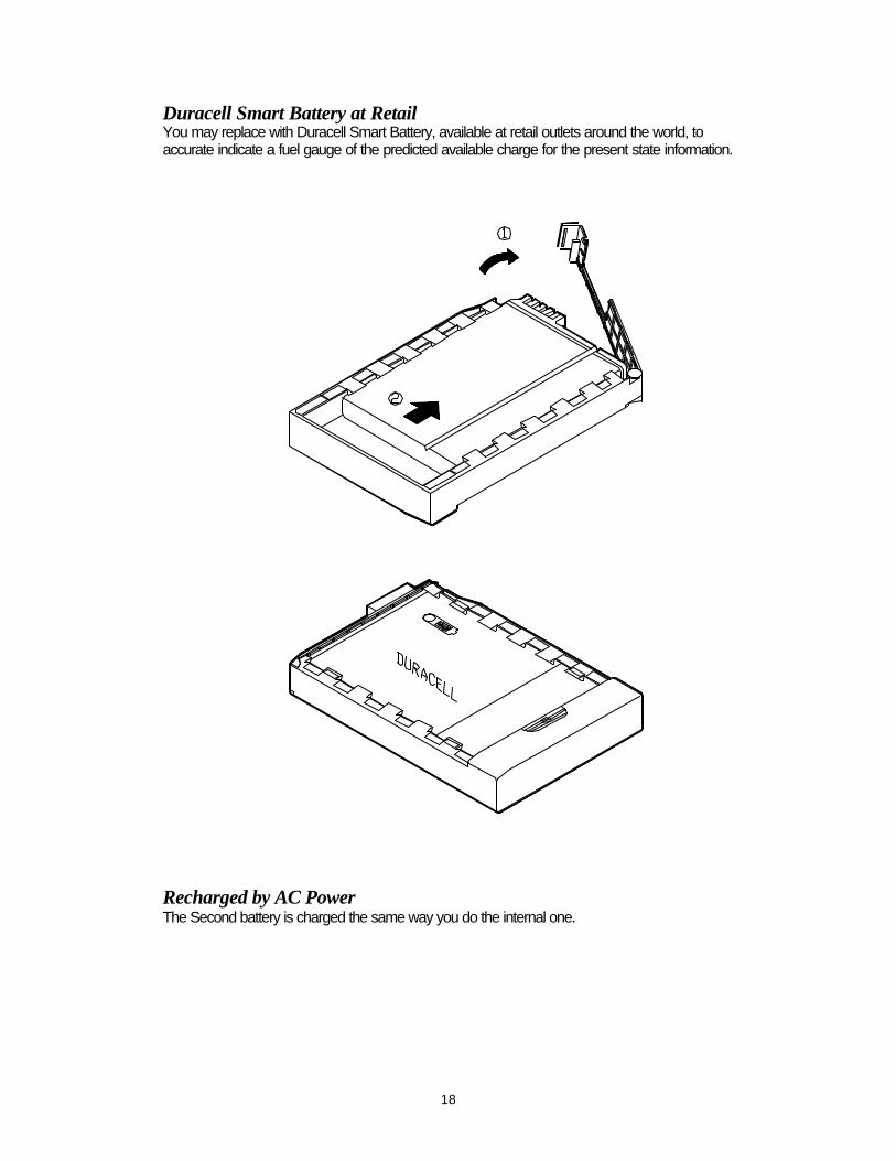
Duracell Smart Battery at Retail You may replace with Duracell Smart Battery, available at retail outlets around the world, to accurate indicate a fuel gauge of the predicted available charge for the present state information.
Recharged by AC Power The Second battery is charged the same way you do the internal one.

19
Operation Hardware Configuration Disconnect all power supply both AC adapter and battery pack before work on any hardware setting.
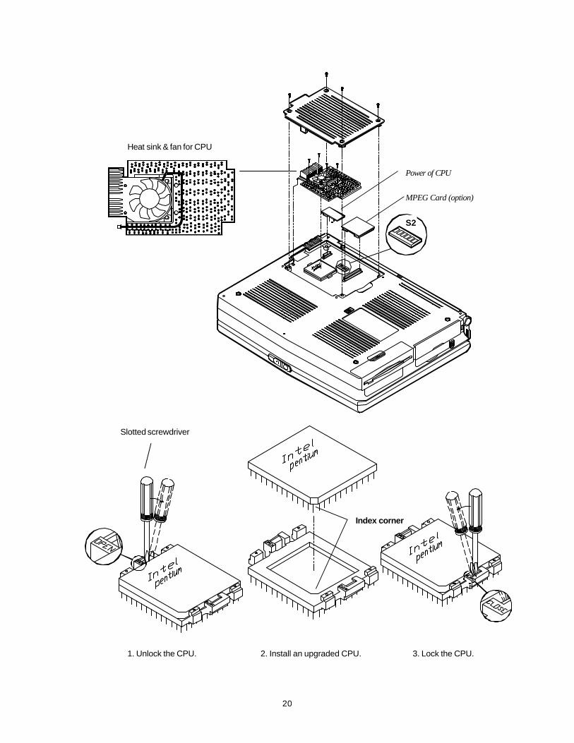
CPU The system is upgradeable with a wide range of speed and voltages of the Intel Pentium processors, providing user with a Zero-Insertion-Force (ZIF) socket to facilitate removal of the Pentium processor and installation of an upgraded one. ZIF Socket 1. Lever along with a slotted screwdriver on the ZIF socket’s OPEN position to unlock the
CPU.
2. Aligning the CPU’s index corner with the socket’s to install the CPU into place.
3. Lever along with a slotted screwdriver on the ZIF socket’s CLOSE position to lock the CPU.
Heat Sink & Fan for CPU 1. Use a sharp-less tool to arrange the cable clockwise along the fan but outside the two
screws.
2. Attach to the installed CPU.
3. Connect the properly seated cable to the mainboard for CPU temperature dissipation.
4. Reinstall the four screws surrounding the fan to fasten the heat sink. (Work at each other’s opposite angle is recommended for equal attachment.)
Speed of CPU Pentium 75 MHz 90 MHz 100 MHz 120 MHz 133 MHz 150 MHz 166 MHz 200 MHz
S2-1 Off On Off On Off On Off Off S2-2 On Off Off Off Off Off Off Off S2-3 Off S2-4 Off S2-5 Off Off Off On On On On Off S2-6 Off Off Off Off Off On On On
Power of CPU The power of CPU varies with the CPU’s voltage supply. You may need to attach the proper circuit board of Power of CPU responding to the CPU you install.
• 3.3 volts • 3.1 volts • 2.9 volts
MPEG Accelerator Card (Option) The MPEG Accelerator Card is optional for multimedia use of the system to playback a variety of video formats. Detailed information is available from the dealer near you upon request.
20
Heat sink & fan for CPU
1. Unlock the CPU. 2. Install an upgraded CPU. 3. Lock the CPU.
Slotted screwdriver
Index corner
S2
Power of CPU
MPEG Card (option)
21
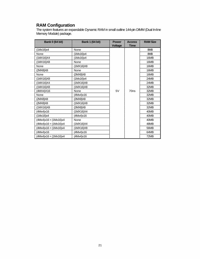
RAM Configuration The system features an expandable Dynamic RAM in small outline 144-pin DIMM (Dual In-line Memory Module) package.
Bank 0 (64 bit) Bank 1 (64 bit) Power Voltage
Access Time
RAM Size
(1Mx16)x4 None 8MB None (1Mx16)x4 8MB (1MX16)X4 (1Mx16)x4 16MB (1MX16)X8 None 16MB None (1MX16)X8 16MB (2MX8)X8 None 16MB None (2MX8)X8 16MB (1MX16)X8 (1Mx16)x4 24MB (1MX16)X4 (1MX16)X8 24MB (1MX16)X8 (1MX16)X8 32MB (4MX4)X16 None 5V 70ns 32MB None (4Mx4)x16 32MB (2MX8)X8 (2MX8)X8 32MB (2MX8)X8 (1MX16)X8 32MB (1MX16)X8 (2MX8)X8 32MB (4Mx4)x16 (1MX16)X4 40MB (1Mx16)x4 (4Mx4)x16 40MB (4Mx4)x16 + (1Mx16)x4 None 40MB (4Mx4)x16 + (1Mx16)x4 (1MX16)X4 48MB (4Mx4)x16 + (1Mx16)x4 (1MX16)X8 56MB (4Mx4)x16 (4Mx4)x16 64MB (4Mx4)x16 + (1Mx16)x4 (4Mx4)x16 72MB
22
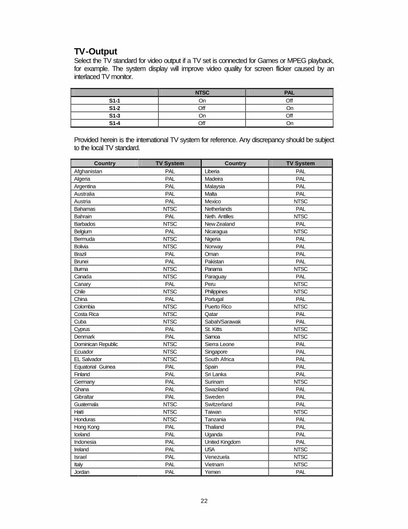
TV-Output Select the TV standard for video output if a TV set is connected for Games or MPEG playback, for example. The system display will improve video quality for screen flicker caused by an interlaced TV monitor.
NTSC PAL S1-1 On Off S1-2 Off On S1-3 On Off S1-4 Off On
Provided herein is the international TV system for reference. Any discrepancy should be subject to the local TV standard.
Country TV System Country TV System Afghanistan PAL Liberia PAL Algeria PAL Madeira PAL Argentina PAL Malaysia PAL Australia PAL Malta PAL Austria PAL Mexico NTSC Bahamas NTSC Netherlands PAL Bahrain PAL Neth. Antilles NTSC Barbados NTSC New Zealand PAL Belgium PAL Nicaragua NTSC Bermuda NTSC Nigeria PAL Bolivia NTSC Norway PAL Brazil PAL Oman PAL Brunei PAL Pakistan PAL Burma NTSC Panama NTSC Canada NTSC Paraguay PAL Canary PAL Peru NTSC Chile NTSC Philippines NTSC China PAL Portugal PAL Colombia NTSC Puerto Rico NTSC Costa Rica NTSC Qatar PAL Cuba NTSC Sabah/Sarawak PAL Cyprus PAL St. Kitts NTSC Denmark PAL Samoa NTSC Dominican Republic NTSC Sierra Leone PAL Ecuador NTSC Singapore PAL EL Salvador NTSC South Africa PAL Equatorial Guinea PAL Spain PAL Finland PAL Sri Lanka PAL Germany PAL Surinam NTSC Ghana PAL Swaziland PAL Gibraltar PAL Sweden PAL Guatemala NTSC Switzerland PAL Haiti NTSC Taiwan NTSC Honduras NTSC Tanzania PAL Hong Kong PAL Thailand PAL Iceland PAL Uganda PAL Indonesia PAL United Kingdom PAL Ireland PAL USA NTSC Israel PAL Venezuela NTSC Italy PAL Vietnam NTSC Jordan PAL Yemen PAL

23
Kenya PAL Yugoslavia PAL Korea South NTSC Zambia PAL Kuwait PAL

24
Bank 0
Bank 1
S1
25
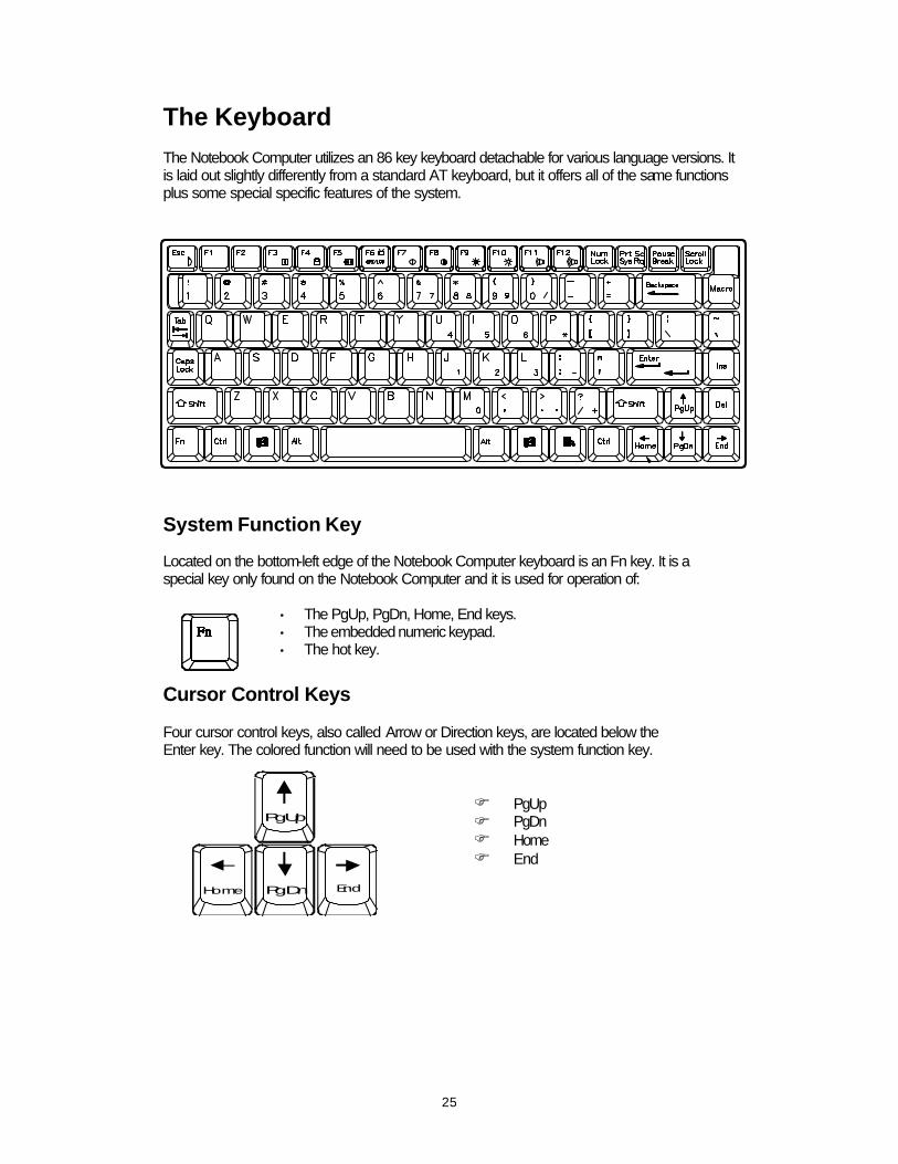
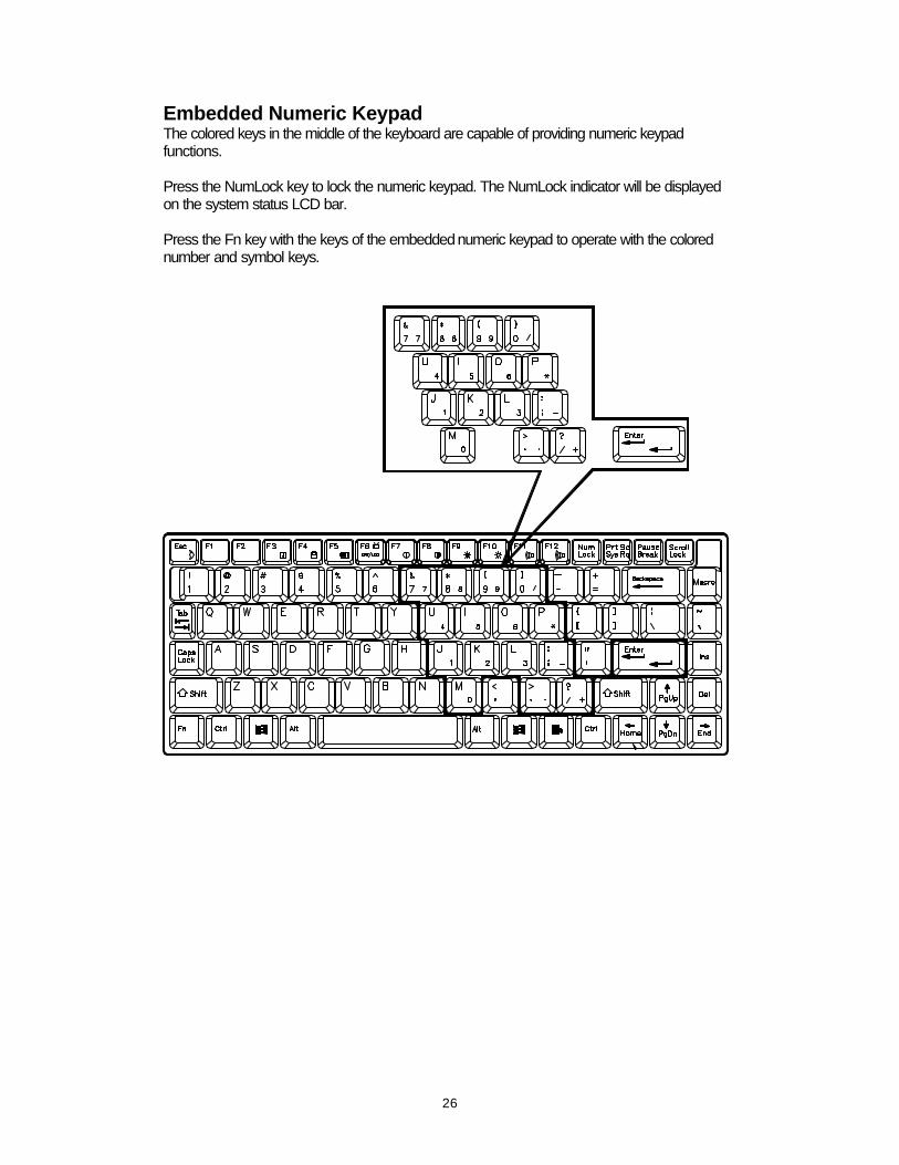
The Keyboard The Notebook Computer utilizes an 86 key keyboard detachable for various language versions. It is laid out slightly differently from a standard AT keyboard, but it offers all of the same functions plus some special specific features of the system.
System Function Key Located on the bottom-left edge of the Notebook Computer keyboard is an Fn key. It is a special key only found on the Notebook Computer and it is used for operation of:
• The PgUp, PgDn, Home, End keys. • The embedded numeric keypad. • The hot key.
Cursor Control Keys Four cursor control keys, also called Arrow or Direction keys, are located below the Enter key. The colored function will need to be used with the system function key.
F PgUp F PgDn F Home F End
PgUp
PgDnHome End
26
Embedded Numeric Keypad The colored keys in the middle of the keyboard are capable of providing numeric keypad functions. Press the NumLock key to lock the numeric keypad. The NumLock indicator will be displayed on the system status LCD bar. Press the Fn key with the keys of the embedded numeric keypad to operate with the colored number and symbol keys.
27
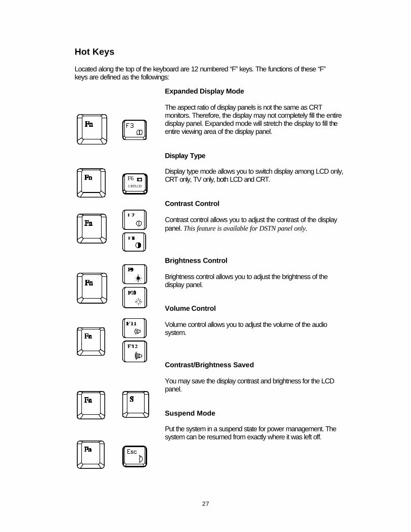
Hot Keys Located along the top of the keyboard are 12 numbered “F” keys. The functions of these “F” keys are defined as the followings:
Expanded Display Mode The aspect ratio of display panels is not the same as CRT monitors. Therefore, the display may not completely fill the entire display panel. Expanded mode will stretch the display to fill the entire viewing area of the display panel. Display Type Display type mode allows you to switch display among LCD only, CRT only, TV only, both LCD and CRT. Contrast Control Contrast control allows you to adjust the contrast of the display panel. This feature is available for DSTN panel only. Brightness Control Brightness control allows you to adjust the brightness of the display panel. Volume Control Volume control allows you to adjust the volume of the audio system. Contrast/Brightness Saved You may save the display contrast and brightness for the LCD panel. Suspend Mode Put the system in a suspend state for power management. The system can be resumed from exactly where it was left off.
F6CRT/LCD
28
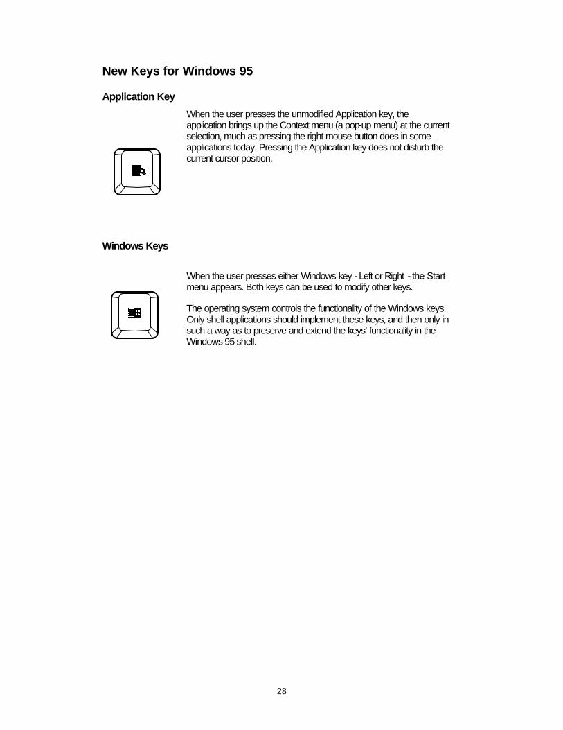
New Keys for Windows 95 Application Key
Windows Keys
When the user presses the unmodified Application key, the application brings up the Context menu (a pop-up menu) at the current selection, much as pressing the right mouse button does in some applications today. Pressing the Application key does not disturb the current cursor position.
When the user presses either Windows key - Left or Right - the Start menu appears. Both keys can be used to modify other keys. The operating system controls the functionality of the Windows keys. Only shell applications should implement these keys, and then only in such a way as to preserve and extend the keys’ functionality in the Windows 95 shell.

29
Storage Disks The Notebook Computer comes equipped with several data storage drives:
• 3.5” Floppy Drive. • 2.5” Hard Drive. • 5.25” CD-ROM Drive.

30
3.5” Floppy Drive and Diskettes The Notebook Computer’s floppy diskette drive is labeled drive A: It is capable of starting the system when a bootable diskette is placed in it. The floppy diskette drive comes designed to be removable for the desired replacement in the 3.5” bay with the Second Battery pack for longer system use time.

31
Inserting/Removing Diskettes n With the label side up, and the metal shutter toward the disk drive, gently insert the
diskette into the drive until the diskette is properly seated. n To remove the diskette from the drive, press the ejection button on the top-right side of the
drive and remove the diskette.

32
2.5” Hard Diskette Drive The 2.5” hard diskette drive supports the LBA mode which overcomes the capacity of 528MB constraint as well as high performance data transfer rate at speed up to 16.6 MB/second. The system will automatically configure the hard disk parameters for any supported IDE drive. If the hard disk drive is not bootable, you must start the system with a bootable diskette in floppy diskette drive A. Refer to your DOS manual for more details about hard disk drives, DOS files, starting your system and formatting disks.
33

34
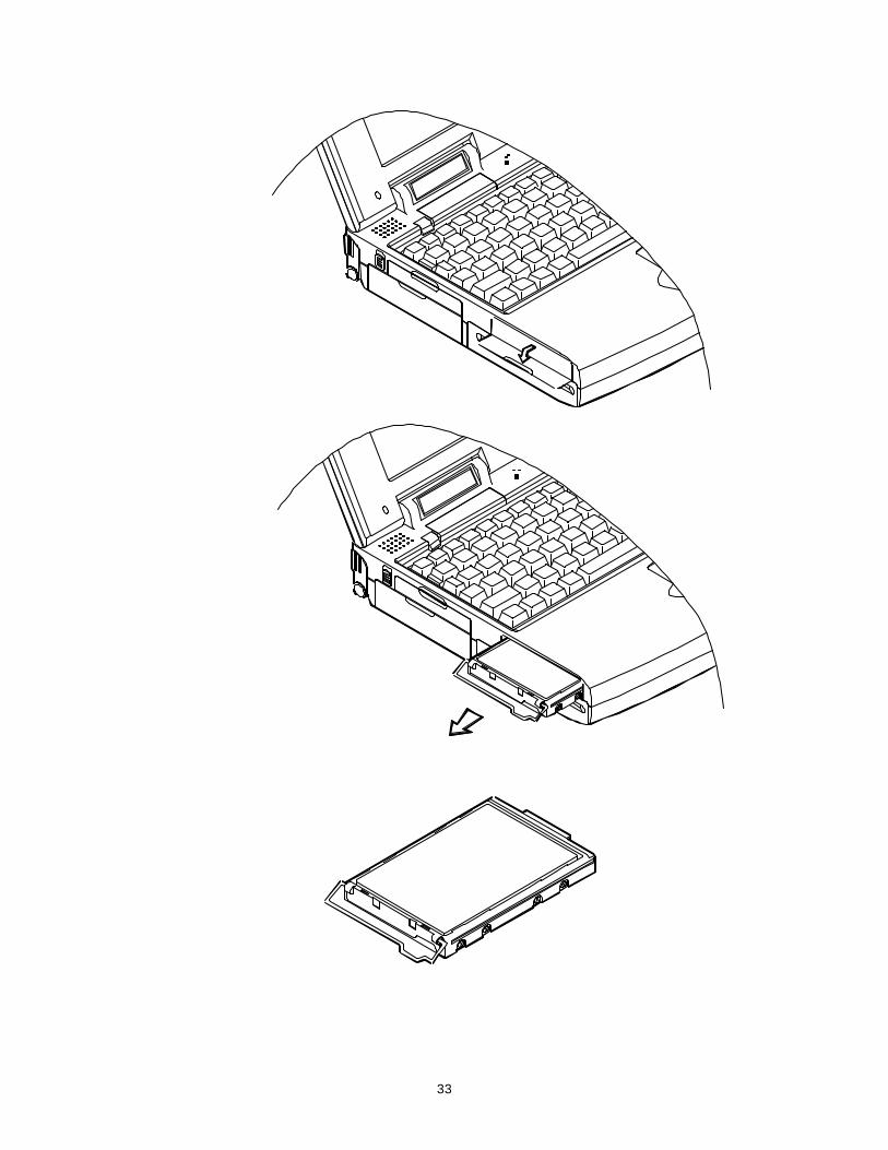
5.25” CD-ROM Drive An IDE 5.25” CD-ROM drive is internally mounted in the system, using the tray loading mechanism for ease of use. The CD-ROM drive provides the performance required for the multimedia applications in a variety of disc types, such as CD-DA, CD-ROM (Mode-1, Mode-2), CD-ROM XA Mode-2 (Form-1, Form-2), Multi-session Photo CD, and CD-I, Video CD compatible.
35
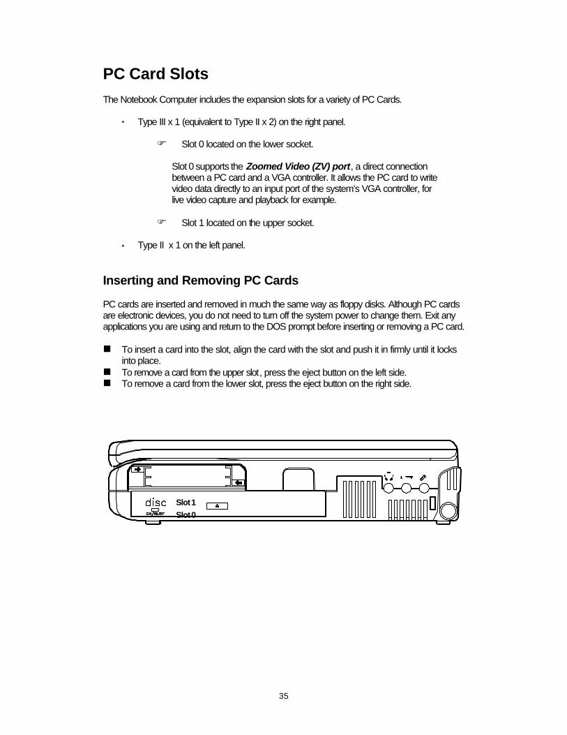
PC Card Slots The Notebook Computer includes the expansion slots for a variety of PC Cards.
• Type III x 1 (equivalent to Type II x 2) on the right panel.
F Slot 0 located on the lower socket. Slot 0 supports the Zoomed Video (ZV) port, a direct connection between a PC card and a VGA controller. It allows the PC card to write video data directly to an input port of the system’s VGA controller, for live video capture and playback for example.
F Slot 1 located on the upper socket.
• Type II x 1 on the left panel. Inserting and Removing PC Cards PC cards are inserted and removed in much the same way as floppy disks. Although PC cards are electronic devices, you do not need to turn off the system power to change them. Exit any applications you are using and return to the DOS prompt before inserting or removing a PC card. n To insert a card into the slot, align the card with the slot and push it in firmly until it locks
into place. n To remove a card from the upper slot, press the eject button on the left side. n To remove a card from the lower slot, press the eject button on the right side.
Slot 0
Slot 1
36
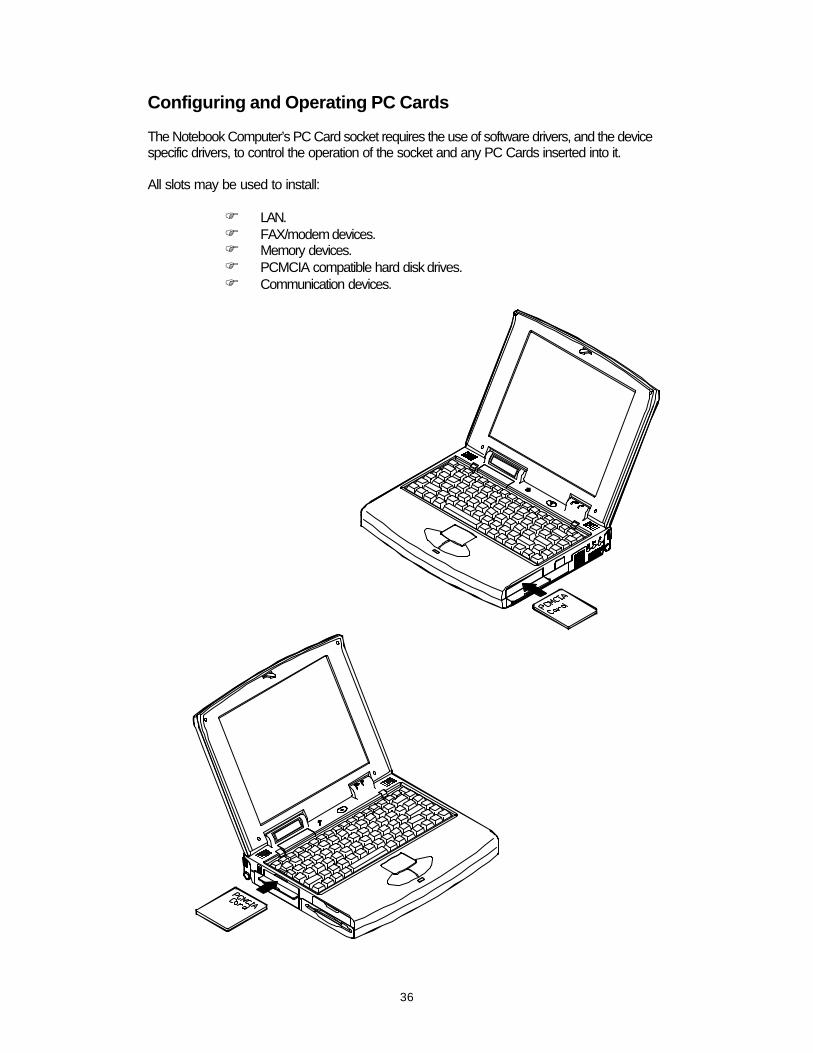
Configuring and Operating PC Cards The Notebook Computer’s PC Card socket requires the use of software drivers, and the device specific drivers, to control the operation of the socket and any PC Cards inserted into it. All slots may be used to install:
F LAN. F FAX/modem devices. F Memory devices. F PCMCIA compatible hard disk drives. F Communication devices.

37
LCD Panel The Notebook Computer’s features the LCD panel display with the followings:
• PCI local bus controller. • 2MB video DRAM. • Capability to support 800x600 (SVGA) resolution DSTN/TFT display. • Super-VGA resolution output to an external monitor. • Ability to output the video to other video display device:
F VGA monitor (CRT) or RGB projector. F TV set.
• Ability to drive both displays of LCD and other video device simultaneously:
F VGA monitor (CRT) or RGB projector.
• VPM (Video Port Manager) provider, the driver-level software, to gain direct control of
the display hardware for video input from:
F ZV-capable PC Card.
38
Power Management The Notebook Computer provides users with power management to manage power consumption while maintain optimal system performance. Standby Mode Standby Mode is the device level power management. Most controllable peripheral devices, such as hard disk and LCD display, will be powered off. If the STANDBY timer expires before any system activity is detected, the system will change from Standby Mode to Suspend Mode.
Suspend Mode Suspend Mode is the system level power management. The CPU and DMA clocks will be halted and all controllable peripheral devices will be turned off. The system may be suspended by:
• Suspend hot key • Suspend timeout • Battery weak
Be sure not to initialize the Suspend Mode when any of the disk drives is accessed such as HDD, FDD and CD-ROM drive. Suspend to Memory Suspend-to-Memory is a 5-volt suspend mode for system power management. Suspend to Disk Suspend-to-Disk is a 0-volt suspend mode for system power management. 1. Use your operating system’s FDISK program to delete all partitions of the hard disk if any
already exists on the target drive.
2. Boot the system from the A: drive and run the 0VMAKFIL.EXE Utility to create the Suspend to Disk partition on the hard disk whose size will accommodate the installed DRAM (n) plus 2MB integrated video RAM.
A:\>0VMAKFIL /Pn
For example, if the system DRAM is 72MB, 0VMAKFIL will create a partition of size about 75MB.
A:\>0VMAKFIL /P72
Note: Rewrite the sector signatures if you partition again the very hard disk.
C:\>0VMAKFIL /PW
3. Re-partition the hard disk using your operating system’s FDISK program.

39
System Resume The system operation can be returned from exactly where it was suspended when a resume event occurs. However, the system may not resume successfully from the Suspend Mode when connected to some external devices, such as PC Card. Resume from Suspend-to-Memory Mode The system may be resumed from Suspend-to-Memory mode by:
• Resume alarm time (hour/minute) • Modem ring • Any keyboard key pressed
Resume from Suspend-to-Disk Mode The system may be resumed from Suspend-to-Disk mode by:
• Power back on

40
Advanced Power Management The system provides the Advanced Power Management (APM) support to further reduce power consumption especially for battery operation. The installation of Advanced Power Management (APM) varies depending on the Operating System (OS) and the software application you are using. Refer to their respective manuals for detailed information.

41
This page is intentionally left blank.

42
Chapter 2: Utilities Overview The Notebook Computer has several built-in software utilities to help you get the most from the system hardware. This chapter discusses:
: Power-On-Self-Test (POST).
: The System Configuration Utility (SCU).
Power On Self Test (POST) The BIOS performs a series of power-on-self-test (POST) to diagnose hardware errors when the system first starts up. During the POST procedure, the POST verifies that the hardware is installed and operational. If a hardware problem exists, the POST routine may halt execution (depending upon the severity of the problem).
43
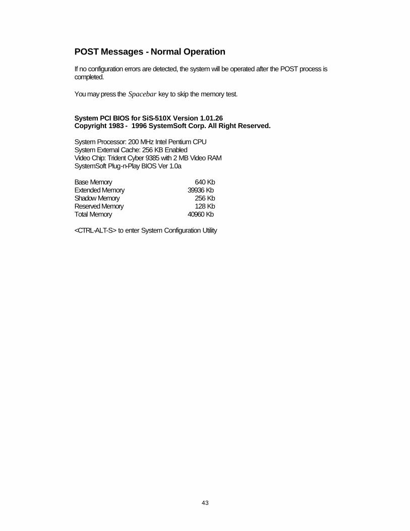
POST Messages - Normal Operation If no configuration errors are detected, the system will be operated after the POST process is completed. You may press the Spacebar key to skip the memory test. System PCI BIOS for SiS-510X Version 1.01.26 Copyright 1983 - 1996 SystemSoft Corp. All Right Reserved. System Processor: 200 MHz Intel Pentium CPU System External Cache: 256 KB Enabled Video Chip: Trident Cyber 9385 with 2 MB Video RAM SystemSoft Plug-n-Play BIOS Ver 1.0a Base Memory 640 Kb Extended Memory 39936 Kb Shadow Memory 256 Kb Reserved Memory 128 Kb Total Memory 40960 Kb <CTRL-ALT-S> to enter System Configuration Utility
44
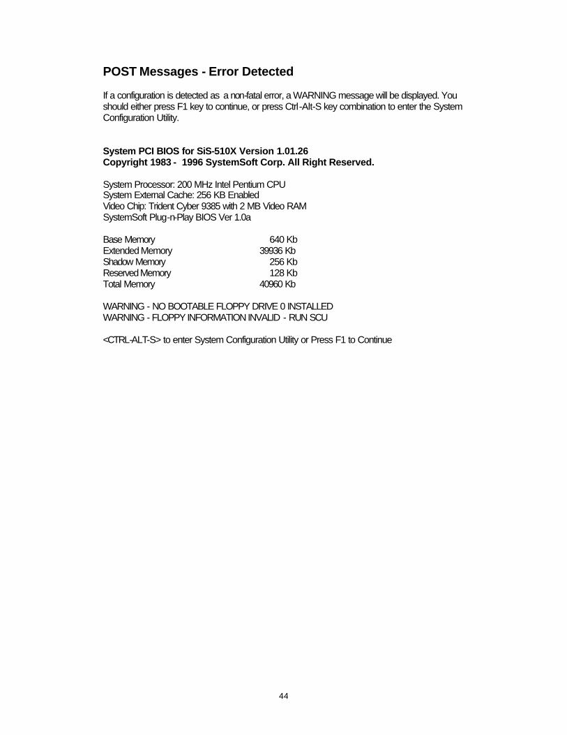
POST Messages - Error Detected If a configuration is detected as a non-fatal error, a WARNING message will be displayed. You should either press F1 key to continue, or press Ctrl-Alt-S key combination to enter the System Configuration Utility. System PCI BIOS for SiS-510X Version 1.01.26 Copyright 1983 - 1996 SystemSoft Corp. All Right Reserved. System Processor: 200 MHz Intel Pentium CPU System External Cache: 256 KB Enabled Video Chip: Trident Cyber 9385 with 2 MB Video RAM SystemSoft Plug-n-Play BIOS Ver 1.0a Base Memory 640 Kb Extended Memory 39936 Kb Shadow Memory 256 Kb Reserved Memory 128 Kb Total Memory 40960 Kb WARNING - NO BOOTABLE FLOPPY DRIVE 0 INSTALLED WARNING - FLOPPY INFORMATION INVALID - RUN SCU <CTRL-ALT-S> to enter System Configuration Utility or Press F1 to Continue
45
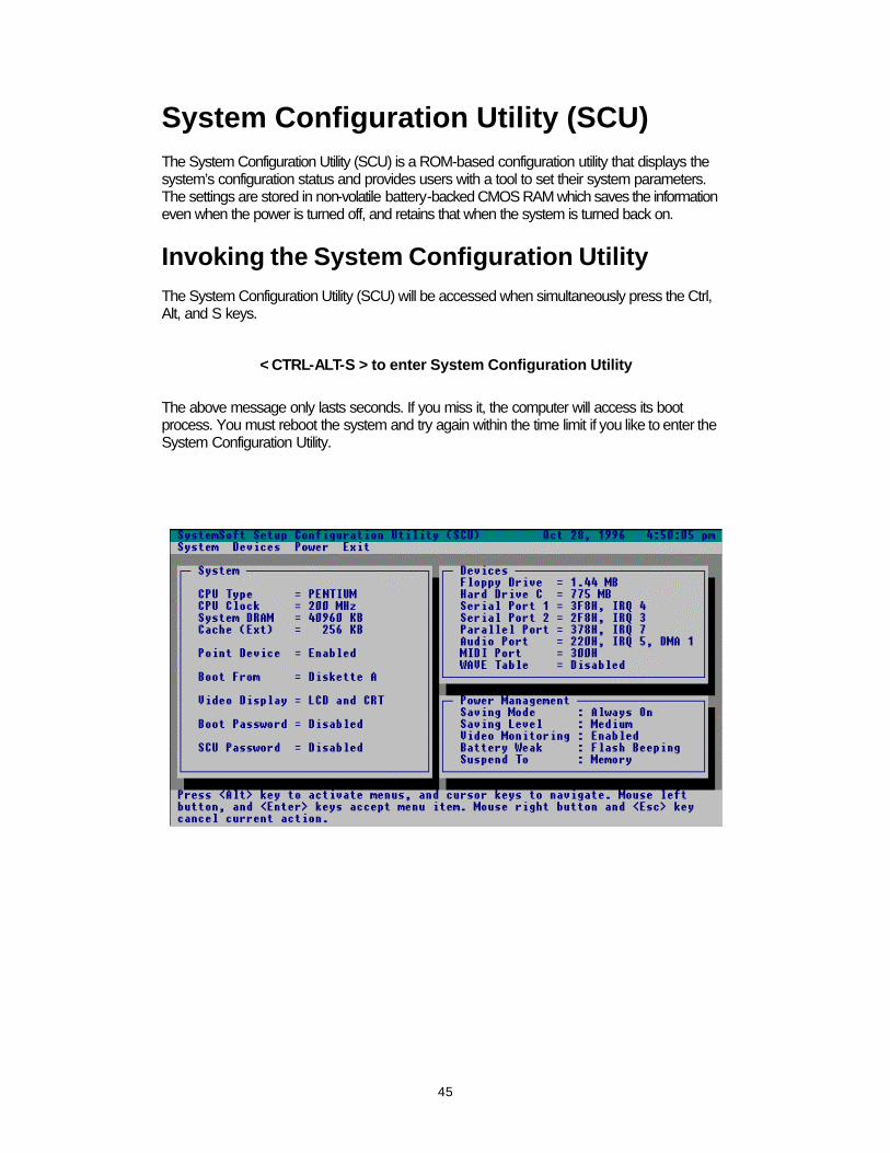
System Configuration Utility (SCU) The System Configuration Utility (SCU) is a ROM-based configuration utility that displays the system’s configuration status and provides users with a tool to set their system parameters. The settings are stored in non-volatile battery-backed CMOS RAM which saves the information even when the power is turned off, and retains that when the system is turned back on.
Invoking the System Configuration Utility The System Configuration Utility (SCU) will be accessed when simultaneously press the Ctrl, Alt, and S keys.
< CTRL-ALT-S > to enter System Configuration Utility
The above message only lasts seconds. If you miss it, the computer will access its boot process. You must reboot the system and try again within the time limit if you like to enter the System Configuration Utility.
46
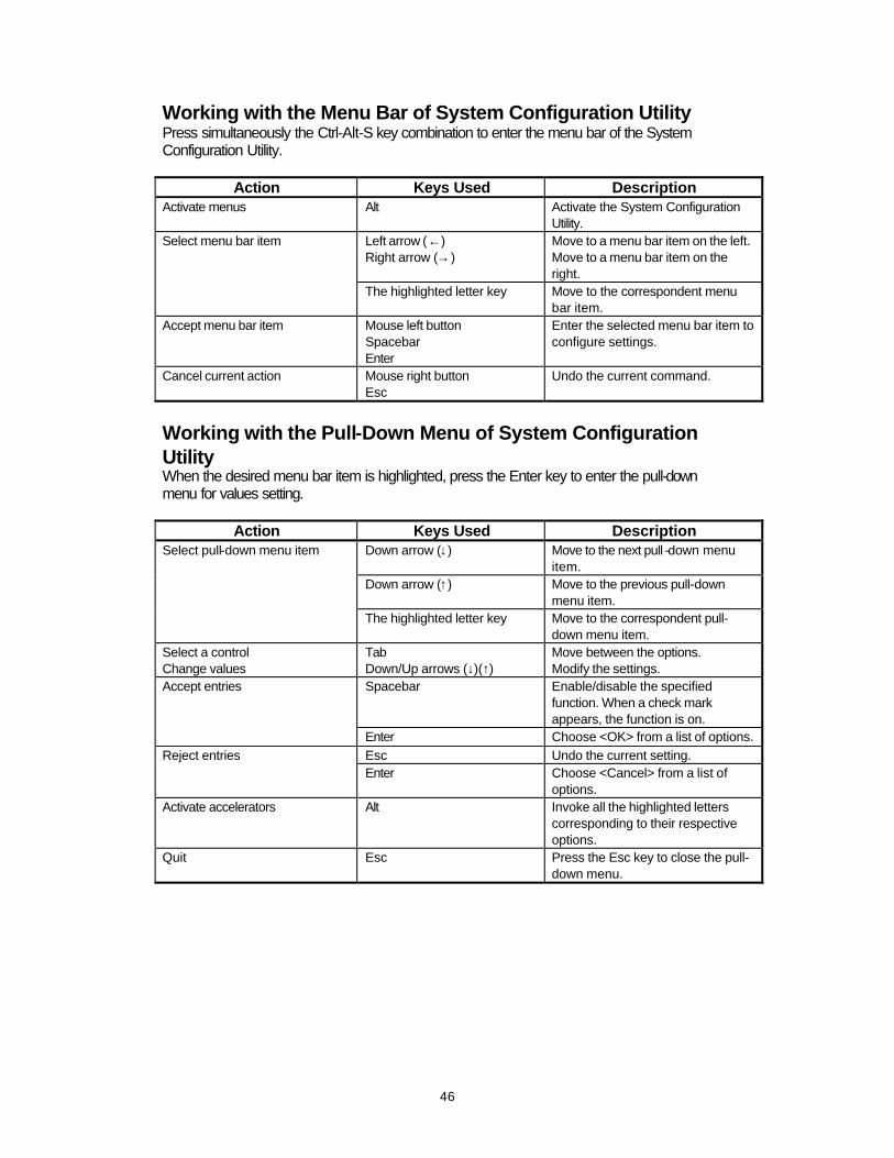
Working with the Menu Bar of System Configuration Utility Press simultaneously the Ctrl-Alt-S key combination to enter the menu bar of the System Configuration Utility.
Action Keys Used Description Activate menus Alt Activate the System Configuration
Utility. Select menu bar item Left arrow (←) Move to a menu bar item on the left. Right arrow (→) Move to a menu bar item on the
right. The highlighted letter key Move to the correspondent menu
bar item. Accept menu bar item Mouse left button
Spacebar Enter
Enter the selected menu bar item to configure settings.
Cancel current action Mouse right button Esc
Undo the current command.
Working with the Pull-Down Menu of System Configuration Utility When the desired menu bar item is highlighted, press the Enter key to enter the pull-down menu for values setting.
Action Keys Used Description Select pull-down menu item Down arrow (↓) Move to the next pull -down menu
item. Down arrow (↑) Move to the previous pull-down
menu item. The highlighted letter key Move to the correspondent pull-
down menu item. Select a control Tab Move between the options. Change values Down/Up arrows (↓)(↑) Modify the settings. Accept entries Spacebar Enable/disable the specified
function. When a check mark appears, the function is on.
Enter Choose <OK> from a list of options. Reject entries Esc Undo the current setting. Enter Choose <Cancel> from a list of
options. Activate accelerators Alt Invoke all the highlighted letters
corresponding to their respective options.
Quit Esc Press the Esc key to close the pull-down menu.
47
Features of the System Configuration Utility
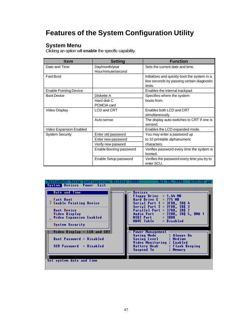
System Menu Clicking an option will enable the specific capability.
Item Setting Function Date and Time Day/month/year
Hour/minute/second Sets the current date and time.
Fast Boot Initializes and quickly boot the system in a few seconds by passing certain diagnostic tests.
Enable Pointing Device Enables the internal trackpad. Boot Device Diskette A Specifies where the system Hard disk C boots from. PCMCIA card Video Display LCD and CRT Enables both LCD and CRT
simultaneously. Auto sense The display auto-switches to CRT if one is
sensed. Video Expansion Enabled Enables the LCD expanded mode. System Security Enter old password You may enter a password up Enter new password to 10 printable alphanumeric Verify new pasword characters. Enable Booting password
Verifies password every time the system is booted.
Enable Setup password
Verifies the password every time you try to enter SCU.

48
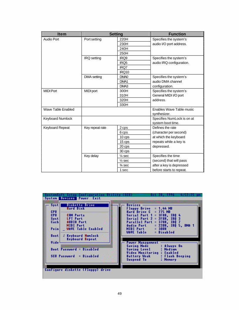
Devices Menu Clicking an option will enable the specific capability.
Item Setting Function Diskette Drive None Specifies a drive type 1.44MB for diskette drive A. Hard Disk Disk Type None No hard disk is installed in the
system. Custom Modifies the values for cylinders,
heads, sectors per track, landing zone, write precomposition and size (MB).
Auto-ID Automatically configures the hard disk parameters for any supported IDE drive.
Enhanced Options LBA mode Enables Logical Block Address (LBA) mode to overcome 528MB barrier.
Multiple sector mode
Enables multiple sector mode to increase sequential data transfers.
Fast PIO mode Enables Fast Programmed Input/output (PIO) mode for high data transfer rate.
COM Ports COM A settings None Specifies the COM A 3F8H, IRQ4 configuration. 2F8H, IRQ3 3E8H, IRQ4 2E8H, IRQ3 COM B settings None Specifies the COM B 3F8H, IRQ4 configuration. 2F8H, IRQ3 3E8H, IRQ4 2E8H, IRQ3 COM B definition Serial port 2 Defines COM B IrDA (HPSIR) hardware. IR (ASKIR) LPT Port Port setting None Specifies the LPT 378H port configuration. 278H 3BCH Port definition SPP mode Standard Parallel Port. EPP mode Enhanced Parallel Port. ECP mode Extended Capabilities Port. IRQ setting IRQ5 Specifies IRQ IRQ7 configuration. ECP DMA setting DMA1 Specifies ECP DMA DMA3 configuration.
49
Item Setting Function
Audio Port Port setting 220H Specifies the system’s 230H audio I/O port address. 240H 250H IRQ setting IRQ9 Specifies the system’s IRQ5 audio IRQ configuration. IRQ7 IRQ10 DMA setting DMA0 Specifies the system’s DMA1 audio DMA channel DMA3 configuration. MIDI Port MIDI port 300H Specifies the system’s 310H General MIDI I/O port 320H address. 330H Wave Table Enabled Enables Wave Table music
synthesizer. Keyboard Numlock Specifies NumLock is on at
system boot time. Keyboard Repeat Key repeat rate 2 cps Defines the rate 6 cps (character per second) 10 cps at which the keyboard 15 cps repeats while a key is 20 cps depressed. 30 cps Key delay ¼ sec Specifies the time ½ sec (second) that will pass ¾ sec after a key is depressed 1 sec before starts to repeat.

50

51
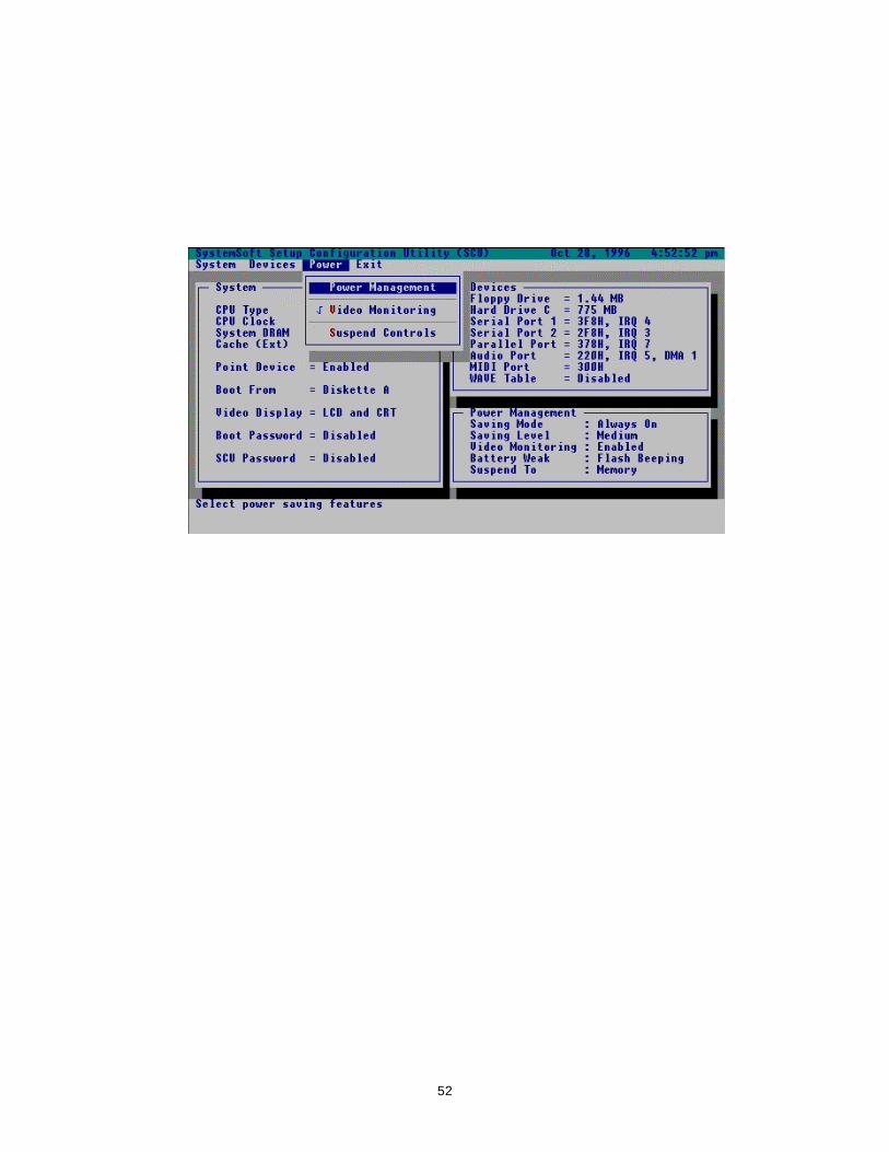
Power Menu Clicking an option will enable the specific capability.
Item Setting Function Power Management Power saving mode Disabled Disables the system’s
power saving features. Battery only Enables the system’s
power saving features only during battery operation.
Always on Enables the system’s power saving features during either battery or AC operation.
Power saving level Low power saving Enables the power saving to its lowest which results in maximum performance but shortest battery life.
Medium power saving Enables the power saving to its medium which results in moderate performance and battery life.
High power saving Enables the power saving to its highest which results in minimum performance but longest battery life.
Video Monitoring Video RAM access will prevent the system from entering a standby mode.
Suspend Controls Battery weak Flash beeping The warning icon flashes on the LCD bar and emits a series of the audio beeps.
Suspend system Automatically suspends the system upon a low battery condition.
Flash only The warning icon flashes on the LCD bar.
Suspend mode Suspend to memory Specifies the suspend mode as 5-volt suspend mode.
Suspend to disk Specifies the suspend mode as 0-volt suspend mode.
Modem ring resume
Resumes the system from suspend-to-memory mode when a modem ring is detected from the serial port where the modem is connected.
Set resume alarm Resume hour Resume minute
Sets the time to resume the system from suspend-to-memory mode.
52
53
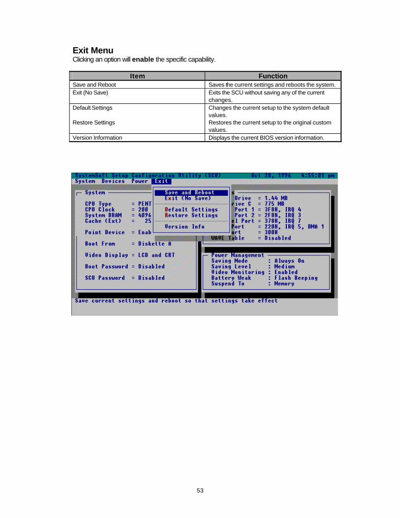
Exit Menu Clicking an option will enable the specific capability.
Item Function Save and Reboot Saves the current settings and reboots the system. Exit (No Save) Exits the SCU without saving any of the current
changes. Default Settings Changes the current setup to the system default
values. Restore Settings Restores the current setup to the original custom
values. Version Information Displays the current BIOS version information.
54
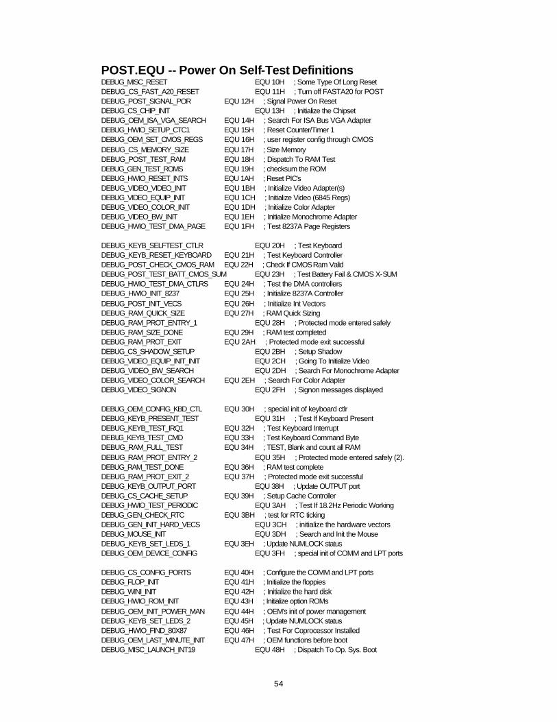
POST.EQU -- Power On Self-Test Definitions DEBUG_MISC_RESET EQU 10H ; Some Type Of Long Reset DEBUG_CS_FAST_A20_RESET EQU 11H ; Turn off FASTA20 for POST DEBUG_POST_SIGNAL_POR EQU 12H ; Signal Power On Reset DEBUG_CS_CHIP_INIT EQU 13H ; Initialize the Chipset DEBUG_OEM_ISA_VGA_SEARCH EQU 14H ; Search For ISA Bus VGA Adapter DEBUG_HWIO_SETUP_CTC1 EQU 15H ; Reset Counter/Timer 1 DEBUG_OEM_SET_CMOS_REGS EQU 16H ; user register config through CMOS DEBUG_CS_MEMORY_SIZE EQU 17H ; Size Memory DEBUG_POST_TEST_RAM EQU 18H ; Dispatch To RAM Test DEBUG_GEN_TEST_ROMS EQU 19H ; checksum the ROM DEBUG_HWIO_RESET_INTS EQU 1AH ; Reset PIC's DEBUG_VIDEO_VIDEO_INIT EQU 1BH ; Initialize Video Adapter(s) DEBUG_VIDEO_EQUIP_INIT EQU 1CH ; Initialize Video (6845 Regs) DEBUG_VIDEO_COLOR_INIT EQU 1DH ; Initialize Color Adapter DEBUG_VIDEO_BW_INIT EQU 1EH ; Initialize Monochrome Adapter DEBUG_HWIO_TEST_DMA_PAGE EQU 1FH ; Test 8237A Page Registers DEBUG_KEYB_SELFTEST_CTLR EQU 20H ; Test Keyboard DEBUG_KEYB_RESET_KEYBOARD EQU 21H ; Test Keyboard Controller DEBUG_POST_CHECK_CMOS_RAM EQU 22H ; Check If CMOS Ram Valid DEBUG_POST_TEST_BATT_CMOS_SUM EQU 23H ; Test Battery Fail & CMOS X-SUM DEBUG_HWIO_TEST_DMA_CTLRS EQU 24H ; Test the DMA controllers DEBUG_HWIO_INIT_8237 EQU 25H ; Initialize 8237A Controller DEBUG_POST_INIT_VECS EQU 26H ; Initialize Int Vectors DEBUG_RAM_QUICK_SIZE EQU 27H ; RAM Quick Sizing DEBUG_RAM_PROT_ENTRY_1 EQU 28H ; Protected mode entered safely DEBUG_RAM_SIZE_DONE EQU 29H ; RAM test completed DEBUG_RAM_PROT_EXIT EQU 2AH ; Protected mode exit successful DEBUG_CS_SHADOW_SETUP EQU 2BH ; Setup Shadow DEBUG_VIDEO_EQUIP_INIT_INIT EQU 2CH ; Going To Initialize Video DEBUG_VIDEO_BW_SEARCH EQU 2DH ; Search For Monochrome Adapter DEBUG_VIDEO_COLOR_SEARCH EQU 2EH ; Search For Color Adapter DEBUG_VIDEO_SIGNON EQU 2FH ; Signon messages displayed DEBUG_OEM_CONFIG_KBD_CTL EQU 30H ; special init of keyboard ctlr DEBUG_KEYB_PRESENT_TEST EQU 31H ; Test If Keyboard Present DEBUG_KEYB_TEST_IRQ1 EQU 32H ; Test Keyboard Interrupt DEBUG_KEYB_TEST_CMD EQU 33H ; Test Keyboard Command Byte DEBUG_RAM_FULL_TEST EQU 34H ; TEST, Blank and count all RAM DEBUG_RAM_PROT_ENTRY_2 EQU 35H ; Protected mode entered safely (2). DEBUG_RAM_TEST_DONE EQU 36H ; RAM test complete DEBUG_RAM_PROT_EXIT_2 EQU 37H ; Protected mode exit successful DEBUG_KEYB_OUTPUT_PORT EQU 38H ; Update OUTPUT port DEBUG_CS_CACHE_SETUP EQU 39H ; Setup Cache Controller DEBUG_HWIO_TEST_PERIODIC EQU 3AH ; Test If 18.2Hz Periodic Working DEBUG_GEN_CHECK_RTC EQU 3BH ; test for RTC ticking DEBUG_GEN_INIT_HARD_VECS EQU 3CH ; initialize the hardware vectors DEBUG_MOUSE_INIT EQU 3DH ; Search and Init the Mouse DEBUG_KEYB_SET_LEDS_1 EQU 3EH ; Update NUMLOCK status DEBUG_OEM_DEVICE_CONFIG EQU 3FH ; special init of COMM and LPT ports DEBUG_CS_CONFIG_PORTS EQU 40H ; Configure the COMM and LPT ports DEBUG_FLOP_INIT EQU 41H ; Initialize the floppies DEBUG_WINI_INIT EQU 42H ; Initialize the hard disk DEBUG_HWIO_ROM_INIT EQU 43H ; Initialize option ROMs DEBUG_OEM_INIT_POWER_MAN EQU 44H ; OEM's init of power management DEBUG_KEYB_SET_LEDS_2 EQU 45H ; Update NUMLOCK status DEBUG_HWIO_FIND_80X87 EQU 46H ; Test For Coprocessor Installed DEBUG_OEM_LAST_MINUTE_INIT EQU 47H ; OEM functions before boot DEBUG_MISC_LAUNCH_INT19 EQU 48H ; Dispatch To Op. Sys. Boot

55
DEBUG_BEGIN_BOOT_CODE EQU 49H ; Jump Into Bootstrap Code DEBUG_CDROM_INIT EQU 0FAh ; Initialize CD-ROM Type DEBUG_S2D_INIT EQU 0FBh ; Initialize S2D Partition
DEBUG codes for PNP BIOS DEBUG_PNP_ENABLE_VERIFY_RTDATA EQU 0A1H ;Enable/Verify R/W Status Runtime Data Area DEBUG_PNP_GET_VERIFY_NVRAM EQU 0A2H ;Get/Verrify R/W Stattus NVRAM data area DEBUG_PNP_SYSTEM_NODES EQU 0A3H ;Resolve System Nodes with the CMOS settings DEBUG_PNP_INITIALIZE_RTDATA EQU 0A4H ;Init. var. in the PNP BIOS Runtime Data area DEBUG_PNP_HOOK_INT15 EQU 0A5H ; Hook INT 15 DEBUG_PNP_SET_COPY_AREA EQU 0A6H ;copy/setup $PnP Install Check in F0000 seg. DEBUG_PNP_OEM_LATE_HOOK EQU 0A7H ; Allow the OEM any Last Minute Hooks DEBUG_PNP_WRITE_PROTECT_RT_DATA EQU 0A8H ;Write protect RTData Area & NVRAM Copy Buffer DEBUG_PNP_INIT_RETURN EQU 0A9H ;return from pnp_init proc
DEBUG codes for the PCI BIOS DEBUG_ROM_MAPPED_OK EQU 0D0H ;check rom signature, 1.x video DEBUG_SEGMENTENABLE_COPYSTATE_1 EQU 0D1H ;enable RAM area in regs DEBUG_COPY_HROM_RAM_1 EQU 0D2H ;copy ROM to RAM in regs DEBUG_SEGMENTENABLE_READWRITE_1 EQU 0D3H ;update segment range attr DEBUG_MAP_MEM_1 EQU 0D4H ;configure memory registers DEBUG_MAP_IO_1 EQU 0D5H ;configure I/O registers DEBUG_MAP_IRQ_1 EQU 0D6H ;configure IRQ assignments DEBUG_CONFIG_COM_REG_1 EQU 0D7H ;turn on PCI device DEBUG_REVISION_1 EQU 0D8H ;2.x video r/w segment DEBUG_OEM_DEV_CLEANUP_1 EQU 0D9H ;OEM defined, rom init DEBUG_PCI_ADDIN_ROM_DISABLE_1 EQU 0DAH ;disable add-in rom card decode DEBUG_RET_PCI_1 EQU 0DBH ;PCI return(config and no video) DEBUG_SEGMENTENABLE_COPYSTATE_2 EQU 0DCH ;enable RAM area in regs DEBUG_COPY_HROM_RAM_2 EQU 0DDH ;copy ROM to RAM in regs DEBUG_SEGMENTENABLE_READWRITE_2 EQU 0DEH ;update segment range attr DEBUG_MAP_MEM_2 EQU 0DFH ;configure memory registers DEBUG_MAP_IO_2 EQU 0E0H ;configure I/O registers DEBUG_MAP_IRQ_2 EQU 0E1H ;configure IRQ assignments DEBUG_CONFIG_COM_REG_2 EQU 0E2H ;turn on PCI device DEBUG_REVISION_2 EQU 0E3H ;2.x video r/w segment DEBUG_OEM_DEV_CLEANUP_2 EQU 0E4H ;OEM defined, rom init DEBUG_PCI_ADDIN_ROM_DISABLE_2 EQU 0E5H ;disable add-in rom card decode DEBUG_RET_PCI_2 EQU 0E6H ;PCI return(config and no video) DEBUG_BRIDGE_HUNT EQU 0E7H ;look for PCI bridge device DEBUG_PCI_IDE_FIND EQU 0E8H ;search IDE controllers on the PCI bus
56
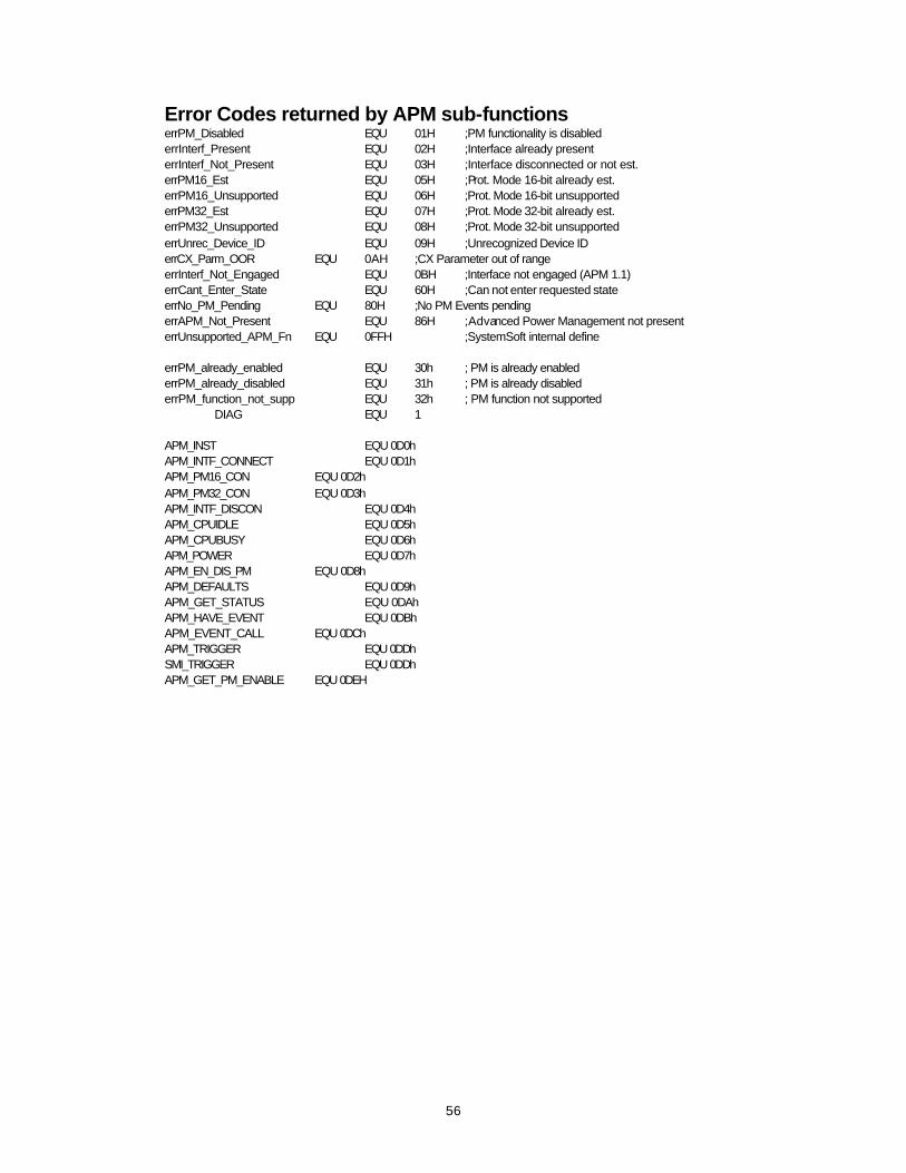
Error Codes returned by APM sub-functions errPM_Disabled EQU 01H ;PM functionality is disabled errInterf_Present EQU 02H ;Interface already present errInterf_Not_Present EQU 03H ;Interface disconnected or not est. errPM16_Est EQU 05H ;Prot. Mode 16-bit already est. errPM16_Unsupported EQU 06H ;Prot. Mode 16-bit unsupported errPM32_Est EQU 07H ;Prot. Mode 32-bit already est. errPM32_Unsupported EQU 08H ;Prot. Mode 32-bit unsupported errUnrec_Device_ID EQU 09H ;Unrecognized Device ID errCX_Parm_OOR EQU 0AH ;CX Parameter out of range errInterf_Not_Engaged EQU 0BH ;Interface not engaged (APM 1.1) errCant_Enter_State EQU 60H ;Can not enter requested state errNo_PM_Pending EQU 80H ;No PM Events pending errAPM_Not_Present EQU 86H ;Advanced Power Management not present errUnsupported_APM_Fn EQU 0FFH ;SystemSoft internal define errPM_already_enabled EQU 30h ; PM is already enabled errPM_already_disabled EQU 31h ; PM is already disabled errPM_function_not_supp EQU 32h ; PM function not supported DIAG EQU 1 APM_INST EQU 0D0h APM_INTF_CONNECT EQU 0D1h APM_PM16_CON EQU 0D2h APM_PM32_CON EQU 0D3h APM_INTF_DISCON EQU 0D4h APM_CPUIDLE EQU 0D5h APM_CPUBUSY EQU 0D6h APM_POWER EQU 0D7h APM_EN_DIS_PM EQU 0D8h APM_DEFAULTS EQU 0D9h APM_GET_STATUS EQU 0DAh APM_HAVE_EVENT EQU 0DBh APM_EVENT_CALL EQU 0DCh APM_TRIGGER EQU 0DDh SMI_TRIGGER EQU 0DDh APM_GET_PM_ENABLE EQU 0DEH
57
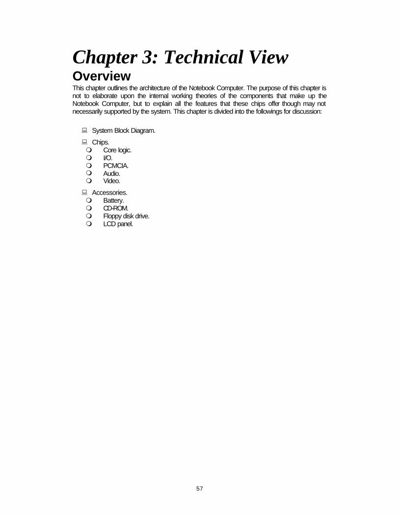
Chapter 3: Technical View Overview This chapter outlines the architecture of the Notebook Computer. The purpose of this chapter is not to elaborate upon the internal working theories of the components that make up the Notebook Computer, but to explain all the features that these chips offer though may not necessarily supported by the system. This chapter is divided into the followings for discussion:
: System Block Diagram.
: Chips. m Core logic. m I/O. m PCMCIA. m Audio. m Video.
: Accessories. m Battery. m CD-ROM. m Floppy disk drive. m LCD panel.

58

59
Chips The following chips have been implemented in the Notebook Computer to interface the microprocessors to I/O devices and memory chips. m SiS5101 PCI Cache Memory Controller. m SiS5102 PCI Local Data Buffer. m SiS5103 System I/O & PMU. m SMC FDC37C669FR PC95/96 Compatible Super I/O Floppy Disk Controller with
Infrared Support. m Omega 82C094 PCI-to-PCMCIA Host Adapter Controller. m ESS ES1788 AudioDrive. m ESS ES690 Wave Table Music Synthesizer. m ESS ES981 Wavetable Sample Set ROM. m Trident Cyber9385 Flat Panel Controller for PCI systems.
60
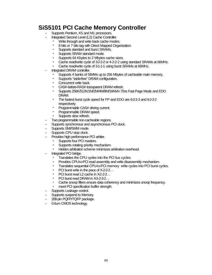
SiS5101 PCI Cache Memory Controller • Supports Pentium, K5 and M1 processors. • Integrated Second Level (L2) Cache Controller.
∗ Write through and write back cache modes. ∗ 8 bits or 7 bits tag with Direct Mapped Organization. ∗ Supports standard and burst SRAMs. ∗ Supports SRAM standard mode. ∗ Supports 64 Kbytes to 2 Mbytes cache sizes. ∗ Cache read/write cycle of 3-2-2-2 or 4-2-2-2 using standard SRAMs at 66MHz. ∗ Cache read/write cycle of 3-1-1-1 using burst SRAMs at 66MHz.
• Integrated DRAM controller. ∗ Supports 4 banks of SIMMs up to 256 Mbytes of cacheable main memory. ∗ Supports “table-free” DRAM configuration. ∗ Concurrent write back. ∗ CAS#-before-RAS# transparent DRAM refresh. ∗ Supports 256K/512K/1M/2M/4M/8M/16MxN 70ns Fast Page Mode and EDO
DRAM. ∗ The fastest burst cycle speed for FP and EDO are 6-3-3-3 and 6-2-2-2
respectively. ∗ Programmable CAS# driving current. ∗ Programmable DRAM speed. ∗ Supports slow refresh.
• Two programmable non-cacheable regions. • Supports synchronous and asynchronous PCI clock. • Supports SMI/SMM mode. • Supports CPU stop clock. • Provides high performance PCI arbiter.
∗ Supports four PCI masters. ∗ Supports rotating priority mechanism. ∗ Hidden arbitration scheme minimizes arbitration overhead.
• Integrated PCI bridge. ∗ Translates the CPU cycles into the PCI bus cycles. ∗ Provides CPU-to-PCI read assembly and write disassembly mechanism. ∗ Translates sequential CPU-to-PCI memory write cycles into PCI burst cycles. ∗ PCI burst write in the pace of X-2-2-2… ∗ PCI burst read L2 cache in X-2-2-2… ∗ PCI burst read DRAM in X-3-2-3-2… ∗ Cache snoop filters ensure data coherency and minimizes snoop frequency. ∗ meet PCI specification buffer strength.
• Supports Leakage control. • Supports suspend to Memory. • 208-pin PQFP/TQFP package. • 0.6um CMOS technology.
61
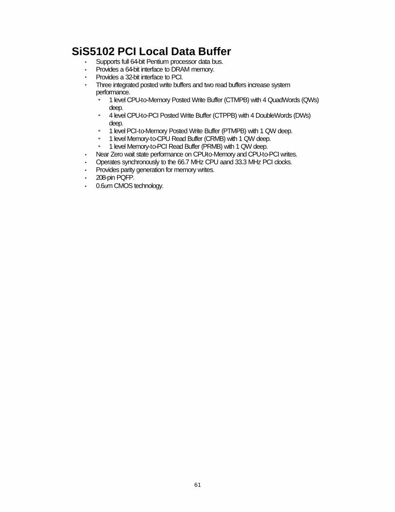
SiS5102 PCI Local Data Buffer • Supports full 64-bit Pentium processor data bus. • Provides a 64-bit interface to DRAM memory. • Provides a 32-bit interface to PCI. • Three integrated posted write buffers and two read buffers increase system
performance. ∗ 1 level CPU-to-Memory Posted Write Buffer (CTMPB) with 4 QuadWords (QWs)
deep. ∗ 4 level CPU-to-PCI Posted Write Buffer (CTPPB) with 4 DoubleWords (DWs)
deep. ∗ 1 level PCI-to-Memory Posted Write Buffer (PTMPB) with 1 QW deep. ∗ 1 level Memory-to-CPU Read Buffer (CRMB) with 1 QW deep. ∗ 1 level Memory-to-PCI Read Buffer (PRMB) with 1 QW deep.
• Near Zero wait state performance on CPU-to-Memory and CPU-to-PCI writes. • Operates synchronously to the 66.7 MHz CPU aand 33.3 MHz PCI clocks. • Provides parity generation for memory writes. • 208-pin PQFP. • 0.6um CMOS technology.
62
SiS5103 System I/O & PMU • Integrated bridge between PCI bus and ISA bus.
∗ Translates PCI bus cycles into ISA bus cycles. ∗ Translates ISA master or DMA cycles into PCI bus cycles. ∗ Provides PCI-to-ISA memory one Double Word Posted Write Buffer.
• Integrated ISA bus compatible logic. ∗ ISA bus controller. ∗ ISA arbiter for ISA master, DMA devices, and refresh. ∗ Built-in two 8237 compatible DMA controllers. ∗ Built-in two 8259A compatible interrupt controllers. ∗ Built-in one 8254 timer.
• Supports reroutibility of four PCI interrupts to any unused IRQ interrupt. • Supports flash ROM. • Built-in RTC with 242 bytes extended CMOS SRAM. • Built-in PCI IDE.
∗ Fully compatible with PCI local bus specification v2.0. ∗ Accommodates 8 bits, 16 bits, and 32 bits data transfer. ∗ Supports PCI burst read/write operation. ∗ Supports read ahead & posted write buffers for concurrent system operation. ∗ Controls two IDE channels and max. connects 4 IDE drives. ∗ Supports PIO mode 4 timing proposal on enhanced IDE specifications. ∗ Programmable command and recovery timing for reads and writes per channel. ∗ Auto IDE channel speed setting with software driver. ∗ Hardware and software chip disable capability. ∗ Supports power down feature.
• Meet PCI specification buffer strength. • Supports CPU thermal detection. • Supports CPU throttling and clock slow down. • Supports software SMI and software stop clock port. • Supports Microsoft APM spec. • Supports user register 32-bit. • External hardware SMI request support.
∗ EXTSUSP, GPIO[3:0], PIO[6:0], UIP [2:0]. • Supports four Power Management Mode.
∗ Local auto doze mode. ∗ Global auto doze mode. ∗ Standby mode. ∗ Suspend mode.
• Supports programmable PMU timer. ∗ Seven sub-doze timer: 31mS/125mS/05.Sec/1Sec/1.5Sec/2Sec/3Sec. ∗ Standby timer: 4 sec ∼ 5 min. ∗ Suspend time: 1 min ∼ 60 min.
63
• Battery Management
∗ AC power indicator. ∗ Multi-level low battery monitor: LB, LLB. ∗ Battery low SMI generation.
• Supports suspend to hard disk. ∗ Read only shadow register.
• Supports suspend to memory. • Supports doze, standby and suspend modes status output pin. • Supports ISA leakage control. • Standby/resume toggle switch. • Standby/resume button switch. • Modem ring/GPIO wake up. • Supports hot docking. • 208-pin PQFP/TQFP package. • 0.6um CMOS technology.
64
SMC FDC37C669FR I/O FDD Controller with IR • 5 volt operation. • Intelligent auto power management. • 16 bit address qualification (option). • 2.88MB super I/O floppy disk controller.
∗ Licensed CMOS 7658 floppy disk controller. ∗ Software and register compatible with SMC’s proprietary 82077AA compatible
core. ∗ Supports two floppy drives directly. ∗ Supports vertical recording format. ∗ 16 byte data FIFO. ∗ 100% IBM compatibility. ∗ Detects all overrun and underrun conditions. ∗ Sophisticated power control circuitry (PCC) including multiple powerdown modes
for reduced power consumption. ∗ DMA enable logic. ∗ Data rate and drive control registers. ∗ Swap drives A and B. ∗ Non-burst mode DMA option. ∗ 48 base I/O address, 7 IRQ and 3 DMA options.
• Floppy disk available on parallel port pins. • Enhanced digital data separator.
∗ 2 Mbps, 1 Mbps, 500 Kbps, 300 Kbps, 250 Kbps data rates. ∗ Programmable precompensation modes.
• Serial Ports ∗ Two high speed NS16C550 compatible UARTs with send/receive 16 byte FIFOs. ∗ Supports 130k and 460k baud. ∗ Programmable baud rate generator. ∗ Modem control circuitry. ∗ Infrared - IrDA, HPSIR, ASKIR, Fast IR (4Mbps IrDA), consumer IR support. ∗ Alternate IR pins (option). ∗ 96 base I/O address and 7 IRQ options.
• Multi-Mode parallel port with ChiProtect. ∗ Standard mode. ∗ IBM PC/XT, PC/AT and PS/2 compatible bidirection parallel port. ∗ Enhanced parallel Port (EPP) compatible. ∗ EPP 1.7 and EPP 1.9 (IEEE 1284 compliant). ∗ Enhanced Capabilities Port (ECP) compatible (IEEE 1284 compliant). ∗ Incorporates ChiProtect circuitry for protection against damage due to printer
power-on. ∗ 192 base I/O address, 7 IRQ and 3 DMA options.
• IDE interface (option). ∗ On-Chip decode and select logic compatible with IBM PC/XT and PC/AT
embedded hard disk drives. ∗ 48 base I/O address and 7 IRQ options.
• Game Port Select Logic ∗ 48 base I/O address.

65
• General purpose address decoder.
∗ 16 byte block decode. ∗ 48 base I/O address options.
• 100 pin QFP and TQFP package.
66
Omega 82C094 PCMCIA Host Adapter Controller Small Form Factor
• Single-chip PCMCIA host controller. • Legacy DMA and serial IRQ to directly support advanced PCI core logic. • Serial power control to support the designs with most PCMCIA power switch IC. • Direct connection to 33Mhz PCI bus and two PCMCIA sockets without glue logic. • 208 pin PQFP or TQFP.
Compatibility
• Compliant with PC Card 95, PCMCIA 2.1, and JEIDA 4.1, ExCA. • Register-set compatible to Intel i82092AA (PPEC) and Intel i82365SL.
Power Management
• Supports CLOCKRUN# of the PCI mobile design guide for power saving. • Intelligent power management for lowest operation power. • Programmable power management with individual socket activity counter.
High Performance
• Four-level FIFO and programmable PCMCIA interface timing. • Five programmable memory windows and two programmable I/O windows per socket.
67
ESS ES1788 AudioDrive The ES1788 AudioDrive can record, compress, and playback voice, sound and music with built-in mixer controls. It consists of an embedded microprocessor, a game compatible 16-bit stereo A/D and D/A, music 16-bit stereo D/A, 20-voice 72 operator FM music synthesizer, MIDI serial port compatible with MPU401 UART mode, dual joystick timers, hardware volume control, DMA control, and ISA bus interface logic. A DSP serial interface allows an external DSP to take over analog resources such as the D/A or A/D converters. Control of I/O address, DMA, and interrupt selection is controlled by system software. Interface to analog inputs is extremely simple. There are stereo inputs for CD-audio, line-in, and an external music synthesis chip or TV, and a mono microphone input to an internal pre-amp. A digital PC speaker input is converted to an analog signal with volume control and is available as an analog output signal. Advanced power management features such as suspend/resume to disk, self timed power down, auto-wakeup, and partial power-down are supported. The ES1788 AudioDrive has a 6 bit master volume control with 64 total steps. The ES1788 AudioDrive is compatible with Sound Blaster PRO version 3.01 voice and music functions as documented in the Sound Blaster Series Developer Kit.
68
ESS ES690
• 32 voices. • General MIDI instrument set - 128 melodic and 47 percussion. • Chorus and reverb effects. • Integrated general MIDI interrupt. • MIDI serial interface. • Supports 512Kx16 up to 8Mx16 ROM’s. • No DAC required. • Context upload for suspend/resume to disk. • Automatic power-down when MIDI input is idle. • 52 pin PQFP.
69
ESS ES981 Wavetable Sample Set ROM
• 512Kx16 bit CMOS ROM. • General MIDI instrument set - 128 melodic and 47 percussion. • Single +5V power supply. • 150 ns fast access time. • Total static operation. • Operating current 60 mA. • 44 pin small outline package (SOP).
70
Trident Cyber9385 Flat Panel Controller The Cyber9385 is a DRAM based, fully integrated LCD, CRT & TV 64 bit multimedia flat panel controller for PCI systems. It provides a flexible, high performance solution for various color depths and solutions. It supports these displays with options for 1, 1.5, 2 and 4 MB, and allows many memory configurations including unified or shared frame buffer architectures. With burst PCI, Extended Data Out (EDO)/Fast Page Mode (FPM) memory support, and the fastest video graphics engine, the Cyber9385 brings VisualReality to PCs. Highly Integrated Design The highly integrated design of the Cyber9385 offers a “no TTL” solution for cost-effective, high performance multimedia subsystem designs for the IBM PC and compatible notebooks. The 64 bit memory data bus, supporting EDO DRAM memory, provides faster data rates for improved system throughput.
71
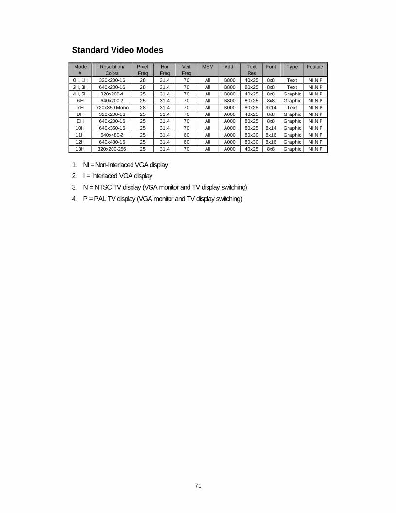
Standard Video Modes Mode Resolution/ Pixel Hor Vert MEM Addr Text Font Type Feature
# Colors Freq Freq Freq Res
0H, 1H 320x200-16 28 31.4 70 All B800 40x25 8x8 Text NI,N,P 2H, 3H 640x200-16 28 31.4 70 All B800 80x25 8x8 Text NI,N,P 4H, 5H 320x200-4 25 31.4 70 All B800 40x25 8x8 Graphic NI,N,P
6H 640x200-2 25 31.4 70 All B800 80x25 8x8 Graphic NI,N,P 7H 720x350-Mono 28 31.4 70 All B000 80x25 9x14 Text NI,N,P DH 320x200-16 25 31.4 70 All A000 40x25 8x8 Graphic NI,N,P EH 640x200-16 25 31.4 70 All A000 80x25 8x8 Graphic NI,N,P 10H 640x350-16 25 31.4 70 All A000 80x25 8x14 Graphic NI,N,P
11H 640x480-2 25 31.4 60 All A000 80x30 8x16 Graphic NI,N,P 12H 640x480-16 25 31.4 60 All A000 80x30 8x16 Graphic NI,N,P 13H 320x200-256 25 31.4 70 All A000 40x25 8x8 Graphic NI,N,P
1. NI = Non-Interlaced VGA display
2. I = Interlaced VGA display
3. N = NTSC TV display (VGA monitor and TV display switching)
4. P = PAL TV display (VGA monitor and TV display switching)
72
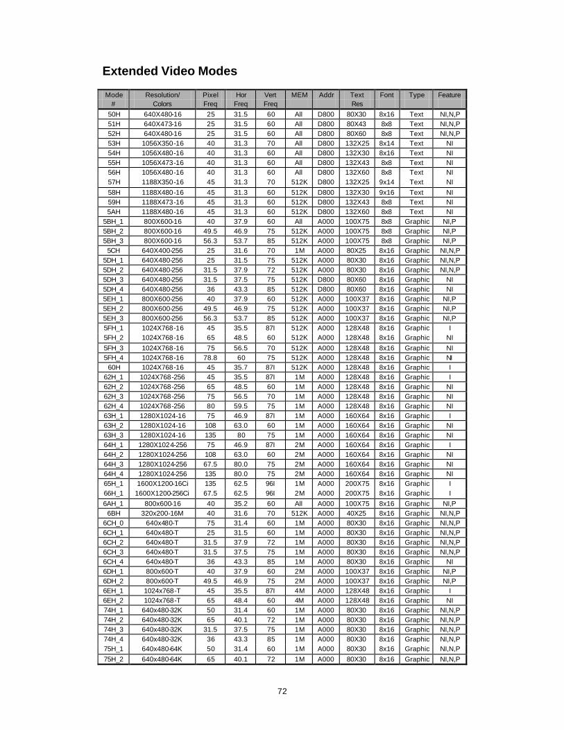
Extended Video Modes Mode Resolution/ Pixel Hor Vert MEM Addr Text Font Type Feature
# Colors Freq Freq Freq Res
50H 640X480-16 25 31.5 60 All D800 80X30 8x16 Text NI,N,P 51H 640X473-16 25 31.5 60 All D800 80X43 8x8 Text NI,N,P 52H 640X480-16 25 31.5 60 All D800 80X60 8x8 Text NI,N,P 53H 1056X350-16 40 31.3 70 All D800 132X25 8x14 Text NI 54H 1056X480-16 40 31.3 60 All D800 132X30 8x16 Text NI 55H 1056X473-16 40 31.3 60 All D800 132X43 8x8 Text NI 56H 1056X480-16 40 31.3 60 All D800 132X60 8x8 Text NI 57H 1188X350-16 45 31.3 70 512K D800 132X25 9x14 Text NI
58H 1188X480-16 45 31.3 60 512K D800 132X30 9x16 Text NI 59H 1188X473-16 45 31.3 60 512K D800 132X43 8x8 Text NI 5AH 1188X480-16 45 31.3 60 512K D800 132X60 8x8 Text NI
5BH_1 800X600-16 40 37.9 60 All A000 100X75 8x8 Graphic NI,P 5BH_2 800X600-16 49.5 46.9 75 512K A000 100X75 8x8 Graphic NI,P 5BH_3 800X600-16 56.3 53.7 85 512K A000 100X75 8x8 Graphic NI,P
5CH 640X400-256 25 31.6 70 1M A000 80X25 8x16 Graphic NI,N,P 5DH_1 640X480-256 25 31.5 75 512K A000 80X30 8x16 Graphic NI,N,P 5DH_2 640X480-256 31.5 37.9 72 512K A000 80X30 8x16 Graphic NI,N,P 5DH_3 640X480-256 31.5 37.5 75 512K D800 80X60 8x16 Graphic NI 5DH_4 640X480-256 36 43.3 85 512K D800 80X60 8x16 Graphic NI 5EH_1 800X600-256 40 37.9 60 512K A000 100X37 8x16 Graphic NI,P 5EH_2 800X600-256 49.5 46.9 75 512K A000 100X37 8x16 Graphic NI,P 5EH_3 800X600-256 56.3 53.7 85 512K A000 100X37 8x16 Graphic NI,P 5FH_1 1024X768-16 45 35.5 87I 512K A000 128X48 8x16 Graphic I 5FH_2 1024X768-16 65 48.5 60 512K A000 128X48 8x16 Graphic NI
5FH_3 1024X768-16 75 56.5 70 512K A000 128X48 8x16 Graphic NI 5FH_4 1024X768-16 78.8 60 75 512K A000 128X48 8x16 Graphic NI
60H 1024X768-16 45 35.7 87I 512K A000 128X48 8x16 Graphic I 62H_1 1024X768-256 45 35.5 87I 1M A000 128X48 8x16 Graphic I 62H_2 1024X768-256 65 48.5 60 1M A000 128X48 8x16 Graphic NI 62H_3 1024X768-256 75 56.5 70 1M A000 128X48 8x16 Graphic NI 62H_4 1024X768-256 80 59.5 75 1M A000 128X48 8x16 Graphic NI 63H_1 1280X1024-16 75 46.9 87I 1M A000 160X64 8x16 Graphic I 63H_2 1280X1024-16 108 63.0 60 1M A000 160X64 8x16 Graphic NI 63H_3 1280X1024-16 135 80 75 1M A000 160X64 8x16 Graphic NI 64H_1 1280X1024-256 75 46.9 87I 2M A000 160X64 8x16 Graphic I 64H_2 1280X1024-256 108 63.0 60 2M A000 160X64 8x16 Graphic NI 64H_3 1280X1024-256 67.5 80.0 75 2M A000 160X64 8x16 Graphic NI 64H_4 1280X1024-256 135 80.0 75 2M A000 160X64 8x16 Graphic NI 65H_1 1600X1200-16Ci 135 62.5 96I 1M A000 200X75 8x16 Graphic I 66H_1 1600X1200-256Ci 67.5 62.5 96I 2M A000 200X75 8x16 Graphic I
6AH_1 800x600-16 40 35.2 60 All A000 100X75 8x16 Graphic NI,P 6BH 320x200-16M 40 31.6 70 512K A000 40X25 8x16 Graphic NI,N,P
6CH_0 640x480-T 75 31.4 60 1M A000 80X30 8x16 Graphic NI,N,P 6CH_1 640x480-T 25 31.5 60 1M A000 80X30 8x16 Graphic NI,N,P 6CH_2 640x480-T 31.5 37.9 72 1M A000 80X30 8x16 Graphic NI,N,P 6CH_3 640x480-T 31.5 37.5 75 1M A000 80X30 8x16 Graphic NI,N,P 6CH_4 640x480-T 36 43.3 85 1M A000 80X30 8x16 Graphic NI 6DH_1 800x600-T 40 37.9 60 2M A000 100X37 8x16 Graphic NI,P 6DH_2 800x600-T 49.5 46.9 75 2M A000 100X37 8x16 Graphic NI,P 6EH_1 1024x768-T 45 35.5 87I 4M A000 128X48 8x16 Graphic I 6EH_2 1024x768-T 65 48.4 60 4M A000 128X48 8x16 Graphic NI 74H_1 640x480-32K 50 31.4 60 1M A000 80X30 8x16 Graphic NI,N,P 74H_2 640x480-32K 65 40.1 72 1M A000 80X30 8x16 Graphic NI,N,P 74H_3 640x480-32K 31.5 37.5 75 1M A000 80X30 8x16 Graphic NI,N,P 74H_4 640x480-32K 36 43.3 85 1M A000 80X30 8x16 Graphic NI,N,P 75H_1 640x480-64K 50 31.4 60 1M A000 80X30 8x16 Graphic NI,N,P
75H_2 640x480-64K 65 40.1 72 1M A000 80X30 8x16 Graphic NI,N,P

73
75H_3 640x480-64K 31.5 37.5 75 1M A000 80X30 8x16 Graphic NI,N,P 75H_4 640x480-64K 36 43.3 85 1M A000 80X30 8x16 Graphic NI,N,P 76H_1 800x600-32K 40 37.9 60 1M A000 100X37 8x16 Graphic NI,P 76H_2 800x600-32K 40 37.9 60 1M A000 100X37 8x16 Graphic NI,P 76H_3 800x600-32K 49.5 46.9 75 1M A000 100X37 8x16 Graphic NI,P

74
Mode Resolution/ Pixel Hor Vert MEM Addr Text Font Type Feature
# Colors Freq Freq Freq Res
77H_1 800x600-64K 40 37.9 60 1M A000 100X37
8x16 Graphic NI,P
77H_2 800x600-64K 49.5 46.9 75 1M A000 100X37
8x16 Graphic NI,P
77H_3 800x600-64K 56.3 53.7 85 1M A000 100X37
8x16 Graphic NI,P
78H_1 1024x768-32K 44.9 35.5 87I 2M A000 128X48
8x16 Graphic I
78H_2 1024x768-32K 65 48.4 60 2M A000 128X48
8x16 Graphic I
78H_3 1024x768-32K 78 60.0 75 2M A000 128X48
8x16 Graphic NI
79H_1 1024x768-64K 44.9 35.5 87I 2M A000 128X48
8x16 Graphic I
79H_2 1024x768-64K 65 48.4 60 2M A000 128X48
8x16 Graphic I
79H_3 1024x768-64K 78 60.0 75 2M A000 128X48
8x16 Graphic NI
7AH_1 1280x1024-32K
78 46.4 87I 4M A000 160X64
8x16 Graphic I
7BH_1 1280x1024-64K
78 46.4 87i 4M A000 160X64
8x16 Graphic I
75
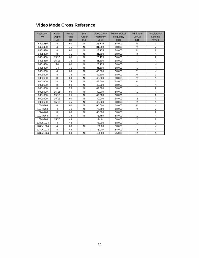
Video Mode Cross Reference Resolution Color Refresh Scan Video Clock Memory Clock Minimum Acceleration
X*Y Depth Rate Order Frequency Frequency DRAM Scheme Bit Hz I/NI MHz MHz MB V/A/H
640x480 4 60 NI 25.175 58.000 ½ V 640x480 4 75 NI 31.500 58.000 ½ V 640x480 8 60 NI 25.175 58.000 ½ A 640x480 8 75 NI 31.500 58.000 ½ A 640x480 15/16 60 NI 25.175 58.000 1 A 640x480 15/16 75 NI 31.500 58.000 1 A
640x480 24 60 NI 25.175 58.000 1 H 640x480 24 75 NI 31.500 58.000 1 H 800x600 4 60 NI 40.000 58.000 ½ V 800x600 4 75 NI 49.500 58.000 ½ V 800x600 8 60 NI 40.000 58.000 ½ A 800x600 8 75 NI 49.500 58.000 ½ A 800x600 8 60 NI 40.000 58.000 1 A 800x600 8 75 NI 49.500 58.000 1 A 800x600 15/16 60 NI 40.000 58.000 1 A 800x600 15/16 75 NI 49.500 58.000 1 A 800x600 15/16 60 NI 40.000 58.000 2 A 800x600 15/16 75 NI 49.500 58.000 2 A
1024x768 4 60 NI 65.000 58.000 ½ V 1024x768 4 75 NI 78.750 58.000 ½ V 1024x768 8 60 NI 65.000 58.000 1 A 1024x768 8 75 NI 78.750 58.000 1 A
1024x768 15/16 43 I 44.9 58.000 2 A 1280x1024 4 43 I 75.000 58.000 1 V 1280x1024 4 60 NI 108.00 58.000 1 V 1280x1024 8 43 I 75.000 58.000 2 A 1280x1024 8 60 NI 108.00 75.000 2 A
76
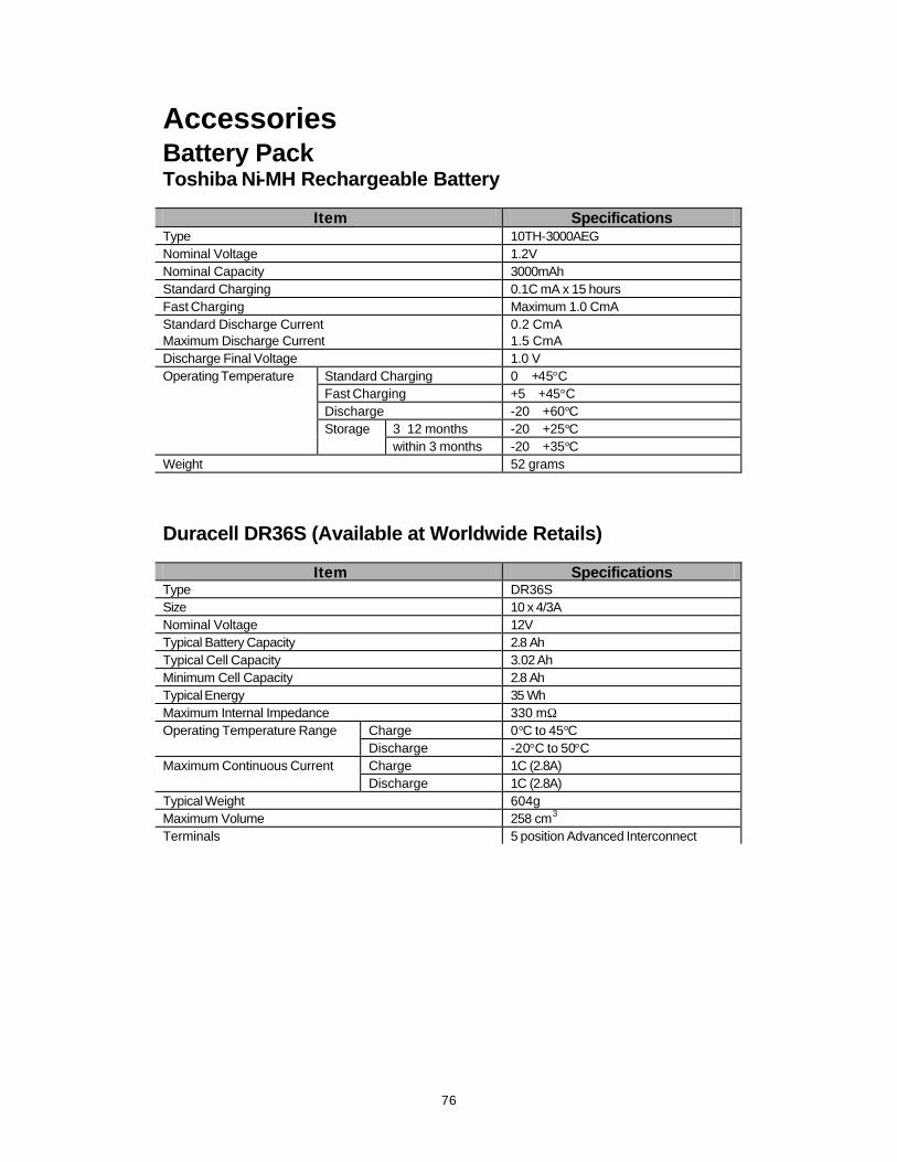
Accessories Battery Pack Toshiba Ni-MH Rechargeable Battery
Item Specifications Type 10TH-3000AEG Nominal Voltage 1.2V Nominal Capacity 3000mAh Standard Charging 0.1C mA x 15 hours Fast Charging Maximum 1.0 CmA Standard Discharge Current 0.2 CmA Maximum Discharge Current 1.5 CmA Discharge Final Voltage 1.0 V Operating Temperature Standard Charging 0 ∼ +45°C Fast Charging +5 ∼ +45°C Discharge -20 ∼ +60°C Storage 3∼12 months -20 ∼ +25°C within 3 months -20 ∼ +35°C Weight 52 grams
Duracell DR36S (Available at Worldwide Retails)
Item Specifications Type DR36S Size 10 x 4/3A Nominal Voltage 12V Typical Battery Capacity 2.8 Ah Typical Cell Capacity 3.02 Ah Minimum Cell Capacity 2.8 Ah Typical Energy 35 Wh Maximum Internal Impedance 330 mΩ Operating Temperature Range Charge 0°C to 45°C Discharge -20°C to 50°C Maximum Continuous Current Charge 1C (2.8A) Discharge 1C (2.8A) Typical Weight 604g Maximum Volume 258 cm3 Terminals 5 position Advanced Interconnect

77
CD-ROM TEAC CD-46E-900 CD-ROM Average Random Access Time 190msec average (6X speed) Full stroke Access Time 450msec average (6X speed) Disk Speed Inner circumstance 3,180rpm Outer circumstance 1,200rpm Data Transfer Rate Average sustained 900KB/sec Programmed I/O 16.7MB/sec. Max. (Mode 0∼4) Multi-word DMA 16.7MB/sec. Max. (Mode 0∼2) Starting Time 8sec. Typical, 32sec max. Data Buffer Capacity 128KB Applicable Discs CD-DA CD-ROM Mode 1, Mode 2 CD-ROM XA Mode 2 (Form 1, Form 2) Photo CD (single/multi -session) Dimensions Height 17.0mm Width 130.6mm Depth 140.5mm (excluding eject button) Weight 320g or less

78
TEAC CD-36E-900 CD-ROM Average Random Access Time 230msec average (6X speed) Full stroke Access Time 480msec average (6X speed) Disk Speed (at 6X speed) Inner circumstance 3,180rpm Outer circumstance 1,200rpm Data Transfer Rate Average sustained 900kB/sec (at 6X speed) Programmed I/O 13.3 MB/sec max. (Mode 0∼3) Multi-word DMA 13.3 MB/sec max. (Mode 0∼1) Starting Time 8sec. Average (when power on or disk loaded) Return Time from Standby Mode 2sec or less Data Buffer Capacity 128KB Applicable Discs CD-DA CD-ROM Mode 1, Mode 2 CD-ROM XA Mode 2 (Form 1, Form 2) Photo CD (single/multi -session) Enhanced CD Dimensions Height 13.7mm Width 130.5mm Depth 140.5mm(excluding eject button) Weight 250g or less

79
TEAC CD-38E-900 CD-ROM Average Random Access Time 200msec average (8X speed) Full stroke Access Time 470msec average (8X speed) Disk Speed (at sextuple speed) Inner circumstance 4,240rpm Outer circumstance 1,600rpm Data Transfer Rate Average sustained 1,200kB/sec Programmed I/O 16.7MB/sec max. (mode 0∼4) Multi-word DMA 16.7MB/sec max. (mode 0∼2) Starting Time 8sec. Average (when power on or disk loaded) Return Time from Standby Mode 2sec or less Data Buffer Capacity 128KB Applicable Discs CD-DA CD-ROM Mode 1, Mode 2 CD-ROM XA Mode 2 (Form 1, Form 2) Photo CD (single/multi -session) Enhanced CD Dimensions Height 13.7mm Width 130.5mm Depth 140.5mm (excluding eject button) Weight 250g or less

80
3.5” Floppy Disk Drive Panasonic JU-226A03F FDD Capacity Normal Density High Density (in bytes) (MFM) (MFM) Unformatted Per Disk 1,000,000 1,666,666 2,000,000 Per Surface 500,000 833,333 1,000,000 Per Track 6,250 10,416 125,000 Formatted (16 sectors/track, 32 sectors/track) Per Disk 655,360 1,310,720 Per Track 4,096 8,192 Per Sector 256 256 Formatted (9 sectors/track, 18 sectors/track) Per Disk 737,280 1,474,560 Per Track 4,608 9,216 Per Sector 512 512 Formatted (15 sectors/track) Per Disk 1,228,800 Per Track 7,680 Per Sector 512 Transfer Rate 250 kbits/s 500 kbits/s 500 kbits/s Latency (avg.) 100 ms 83 ms 100 ms Access Time Track to Track 3 ms 3 ms 3 ms Average (including settling and latency) 194 ms 177 ms 194 ms Settling Time 15 ms 15 ms 15 ms Minimum Turn Around Delay 18 ms 18 ms 18 ms Motor Start Time 500 ms 500 ms 500 ms Motor Rotation Select Delay 500 ms 500 ms 500 ms Dimensions (including front panel) Width 101.6 mm Height 12.7 mm Depth 110.0 mm
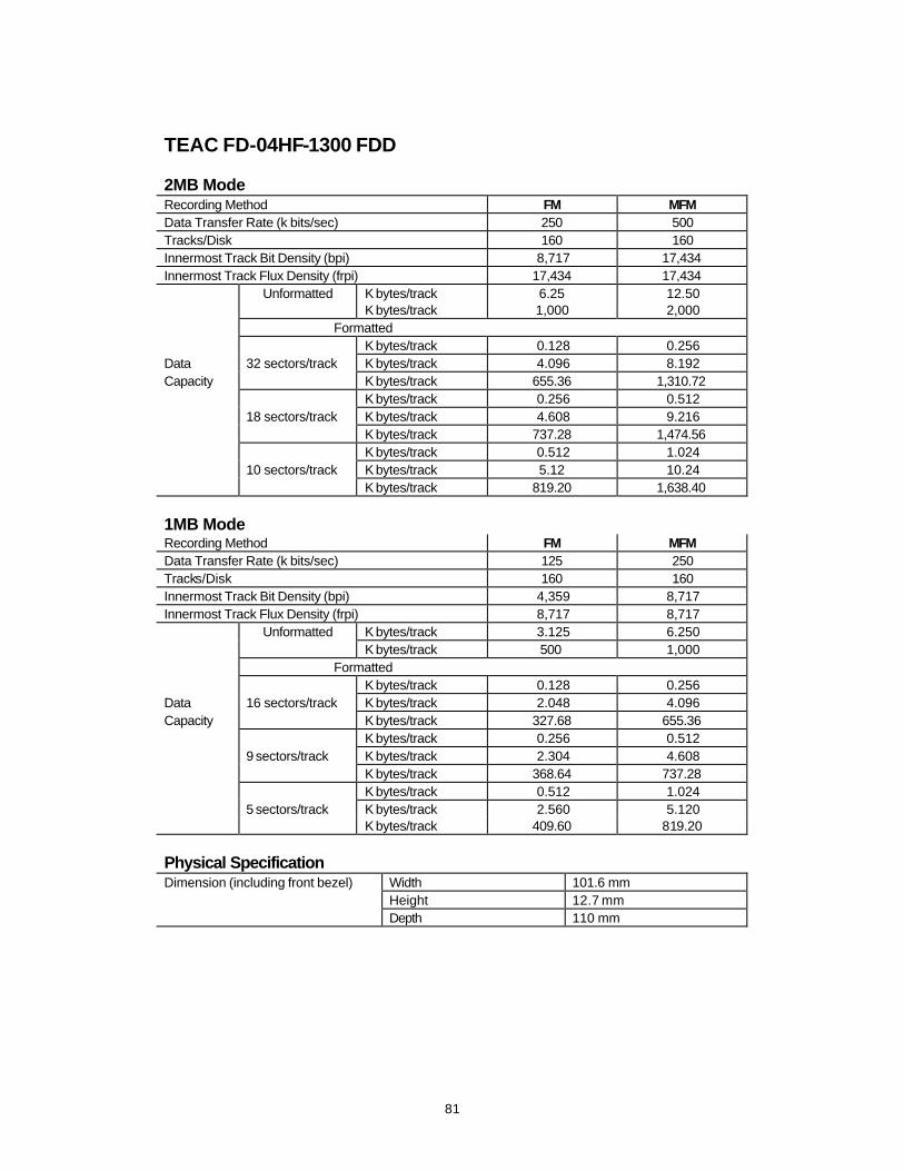
81
TEAC FD-04HF-1300 FDD 2MB Mode Recording Method FM MFM Data Transfer Rate (k bits/sec) 250 500 Tracks/Disk 160 160 Innermost Track Bit Density (bpi) 8,717 17,434 Innermost Track Flux Density (frpi) 17,434 17,434
Unformatted K bytes/track 6.25 12.50 K bytes/track 1,000 2,000 Formatted K bytes/track 0.128 0.256 Data 32 sectors/track K bytes/track 4.096 8.192 Capacity K bytes/track 655.36 1,310.72 K bytes/track 0.256 0.512 18 sectors/track K bytes/track 4.608 9.216 K bytes/track 737.28 1,474.56 K bytes/track 0.512 1.024 10 sectors/track K bytes/track 5.12 10.24 K bytes/track 819.20 1,638.40 1MB Mode Recording Method FM MFM Data Transfer Rate (k bits/sec) 125 250 Tracks/Disk 160 160 Innermost Track Bit Density (bpi) 4,359 8,717 Innermost Track Flux Density (frpi) 8,717 8,717
Unformatted K bytes/track 3.125 6.250 K bytes/track 500 1,000 Formatted K bytes/track 0.128 0.256 Data 16 sectors/track K bytes/track 2.048 4.096 Capacity K bytes/track 327.68 655.36 K bytes/track 0.256 0.512 9 sectors/track K bytes/track 2.304 4.608 K bytes/track 368.64 737.28 K bytes/track 0.512 1.024 5 sectors/track K bytes/track 2.560 5.120 K bytes/track 409.60 819.20 Physical Specification Dimension (including front bezel) Width 101.6 mm Height 12.7 mm Depth 110 mm

82
LCD Panel Sanyo LM-JA53-22NTK 12.1” DSTN
Item Specification Package dimension 276.5mm(W)x199.0mm(H)x8.0mm(D) Structure 800(W)xRGB(W)x600(H) Dot size 0.0871mm(W)x0.2913mm(H) Dot pitch 0.1021mm(W)x0.3063mm(H) Bezel opening area 250.0mm(W)x188.5mm(H) Power supply voltage Minimum 3.0V Maximum 5.5V Viewing angle range θ=0° Minimum 15° θ=90° Minimum 30° θ=180° Minimum 20° θ=270° Minimum 30° Contrast ratio (φ=0°) Minimum 15, typical 30 Response time (φ=0°) Rise Typical 150 ms, maximum 200 ms Fall Typical 150 ms, maximum 200 ms

83
Samsung LT104S4-151 10.4” TFT
Item Specification Display area 211.2mm(H)x158.4mm(V) (10.4” diagonal) Number of dots 800x600 pixel Pixel pitch 0.264mm(H)x0.264mm(W) Pixel arrangement RGB vertical stripe Display colors 262,144 colors Viewing angle 6 oclcok Display mode Normal white Module size 245.5mm(W)x179.4mm(H)x7.7mm(D) Weight 400g (max.) Contrast ratio (θ=0°, φ=0°) 80:1 (min.) Response time at 25° Rise 20 (typical) θ=0°, φ=0° Fall 30 (typical) Luminance 70 cd/m2 (typical) Viewing angle Horizontal-left 45° Horizontal-right 45° Vertical -high 10° Vertical-low 30° Power supply voltage Minimum 4.75V Typical 5.0V Maximum 5.25V
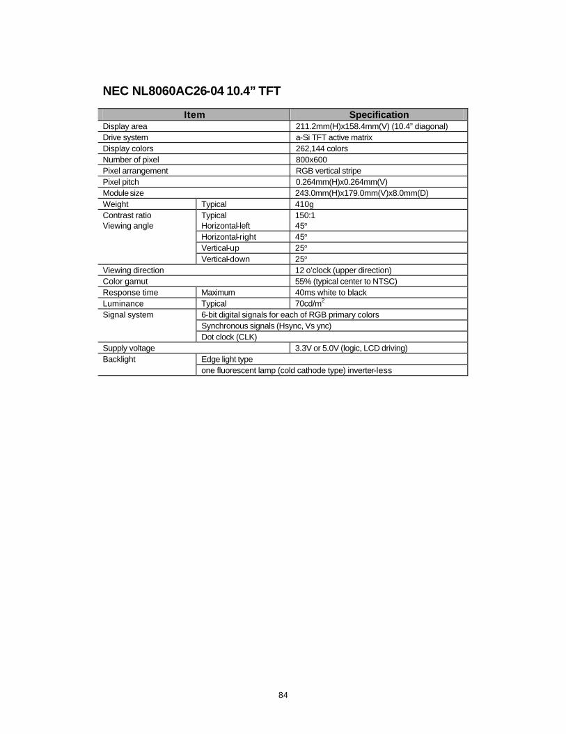
84
NEC NL8060AC26-04 10.4” TFT
Item Specification Display area 211.2mm(H)x158.4mm(V) (10.4” diagonal) Drive system a-Si TFT active matrix Display colors 262,144 colors Number of pixel 800x600 Pixel arrangement RGB vertical stripe Pixel pitch 0.264mm(H)x0.264mm(V) Module size 243.0mm(H)x179.0mm(V)x8.0mm(D) Weight Typical 410g Contrast ratio Typical 150:1 Viewing angle Horizontal-left 45° Horizontal-right 45° Vertical-up 25° Vertical-down 25° Viewing direction 12 o’clock (upper direction) Color gamut 55% (typical center to NTSC) Response time Maximum 40ms white to black Luminance Typical 70cd/m2 Signal system 6-bit digital signals for each of RGB primary colors Synchronous signals (Hsync, Vs ync) Dot clock (CLK) Supply voltage 3.3V or 5.0V (logic, LCD driving) Backlight Edge light type one fluorescent lamp (cold cathode type) inverter-less
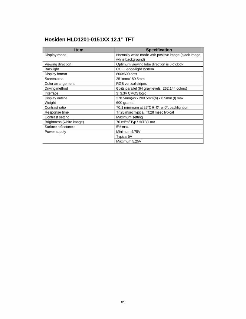
85
Hosiden HLD1201-0151XX 12.1” TFT
Item Specification Display mode Normally white mode with positive image (black image,
white background) Viewing direction Optimum viewing lobe direction is 6 o’clock Backlight CCFL edge-light system Display format 800x600 dots Screen area 251mmx189.5mm Color arrangement RGB vertical stripes Driving method 6 b its parallel (64 gray levels=262,144 colors) Interface 3∼3.3V CMOS logic Display outline 278.5mm(w) x 200.5mm(h) x 8.5mm (t) max. Weight 600 grams Contrast ratio 70:1 minimum at 25°C θ=0°, φ=0°, backlight on Response time Tr:28 msec typical, Tf:28 msec typical Contrast setting Maximum setting Brightness (white image) 70 cd/m2 Typ / If=TBD mA Surface reflectance 5% max. Power supply Minimum 4.75V Typical 5V Maximum 5.25V

86
Samsung LT121S1-103 12.1” TFT
Item Specification Display area 246.0mm(H)x184.5mm(V) (12.1” diagonal) Number of dots 800x600 pixel Pixel pitch 0.3075mm(H)x0.3075mm(W) Pixel arrangement RGB vertical stripe Display colors 262,144 colors Viewing angle 6 o’clcok Display mode Normal white Module size 275.0mm(W)x200.0mm(H)x8.0mm(D) Contrast ratio (θ=0°, φ=0°) 80:1 (min.) Response time at 25° Rise 20 (typical) θ=0°, φ=0° Fall 30 (typical) Luminance 70 cd/m2 (typical) Viewing angle Horizontal-left 45° Horizontal-right 45° Vertical -high 10° Vertical-low 30° Power supply voltage Minimum 3.0V Typical 3.3V Maximum 3.6V
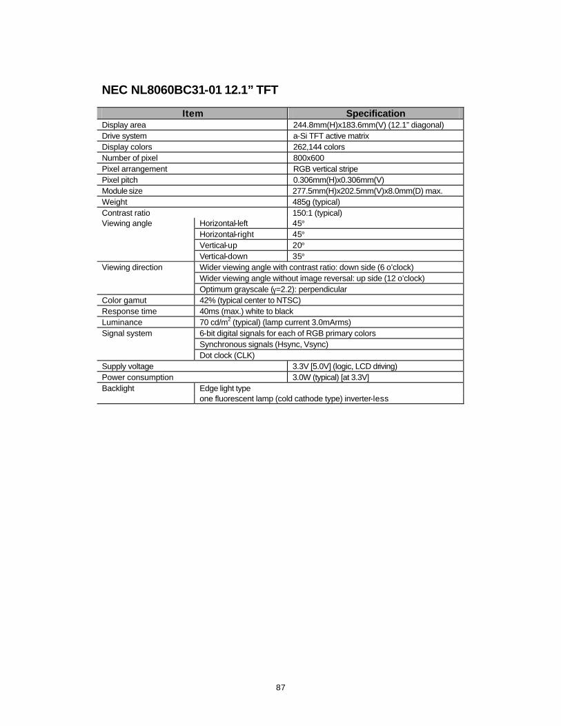
87
NEC NL8060BC31-01 12.1” TFT
Item Specification Display area 244.8mm(H)x183.6mm(V) (12.1” diagonal) Drive system a-Si TFT active matrix Display colors 262,144 colors Number of pixel 800x600 Pixel arrangement RGB vertical stripe Pixel pitch 0.306mm(H)x0.306mm(V) Module size 277.5mm(H)x202.5mm(V)x8.0mm(D) max. Weight 485g (typical) Contrast ratio 150:1 (typical) Viewing angle Horizontal-left 45° Horizontal-right 45° Vertical-up 20° Vertical-down 35° Viewing direction Wider viewing angle with contrast ratio: down side (6 o’clock) Wider viewing angle without image reversal: up side (12 o’clock) Optimum grayscale (γ=2.2): perpendicular Color gamut 42% (typical center to NTSC) Response time 40ms (max.) white to black Luminance 70 cd/m2 (typical) (lamp current 3.0mArms) Signal system 6-bit digital signals for each of RGB primary colors Synchronous signals (Hsync, Vsync) Dot clock (CLK) Supply voltage 3.3V [5.0V] (logic, LCD driving) Power consumption 3.0W (typical) [at 3.3V] Backlight Edge light type one fluorescent lamp (cold cathode type) inverter-less
88
Chapter 4: Parts & Circuit This chapter provides both the parts list and the circuit diagrams for engineers to maintain the Notebook system.
: Parts List. m Top Case & Assemblies. m Bottom Case & Assemblies. m Display Panel & Assemblies. m CD-ROM. m Floppy Disk Drive. m Hard Disk Drive. m Second Battery.
: Circuit Diagrams. m Mainboard. 77-62000-D03 m DC/DC. 77-6200C-D03 m LCD Bar. 77-62006-D01 m Switch Board. 77-6200S-D02 m 8/16MB Memory. 77-6202T-D71 m 32MB Memory. 77-2205T-060 m 40MB Memory. 77-2205T-A61 m 3.3V Power. 77-620A5-D10 m 3.1V/2.9V Power. 77-620A5-D31 m Panel Data.
F DSTN 12.1” Sanyo 77-6200Z-D01 F TFT 10.4” NEC 77-6220Z-D11 F TFT 10.4” Samsung 77-6220Z-D21 F TFT 12.1” NEC/Samsung 77-6220Z-D02 F TFT 12.1” Hosiden 77-6220Z-D30

89

90
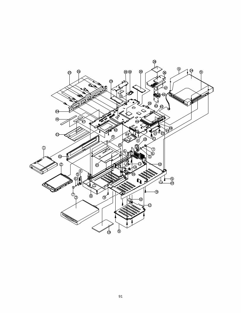
91

92

93
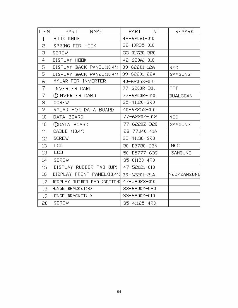
94
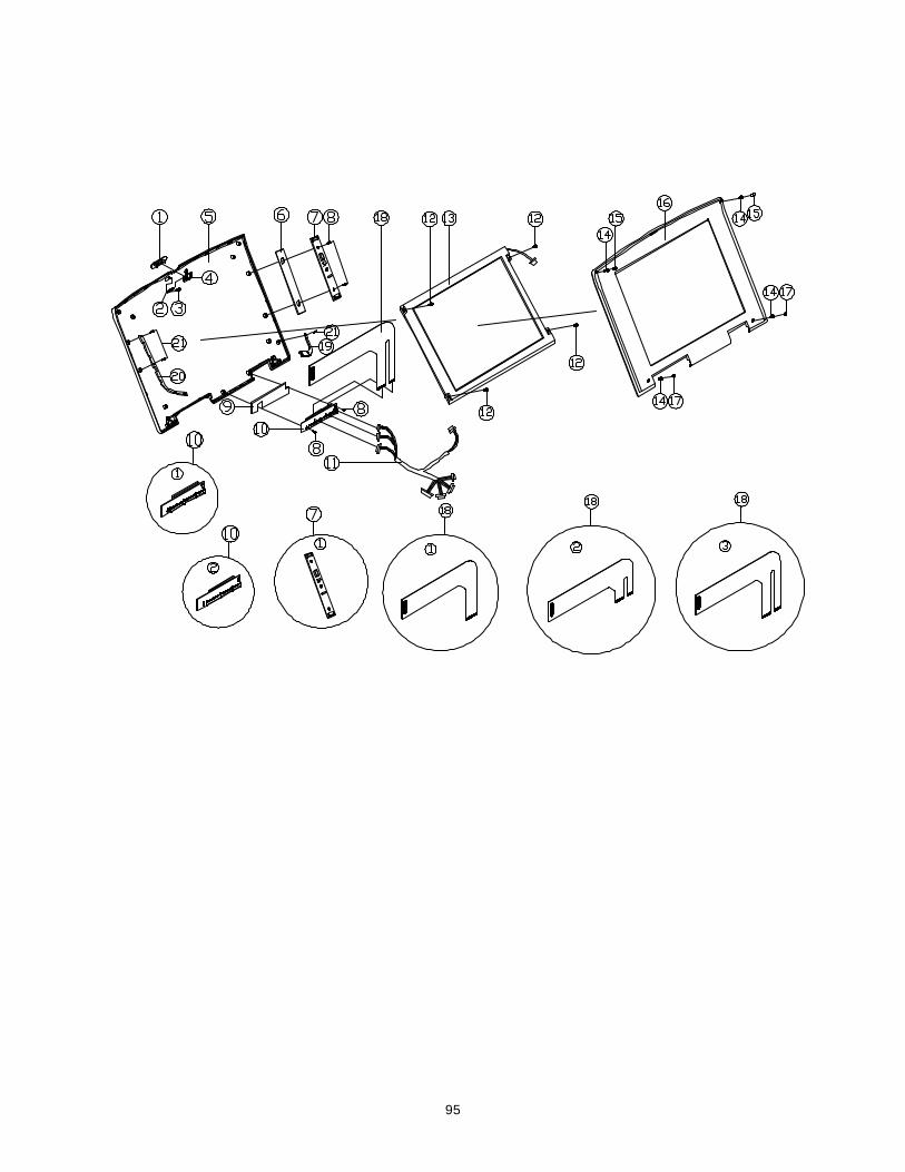
95
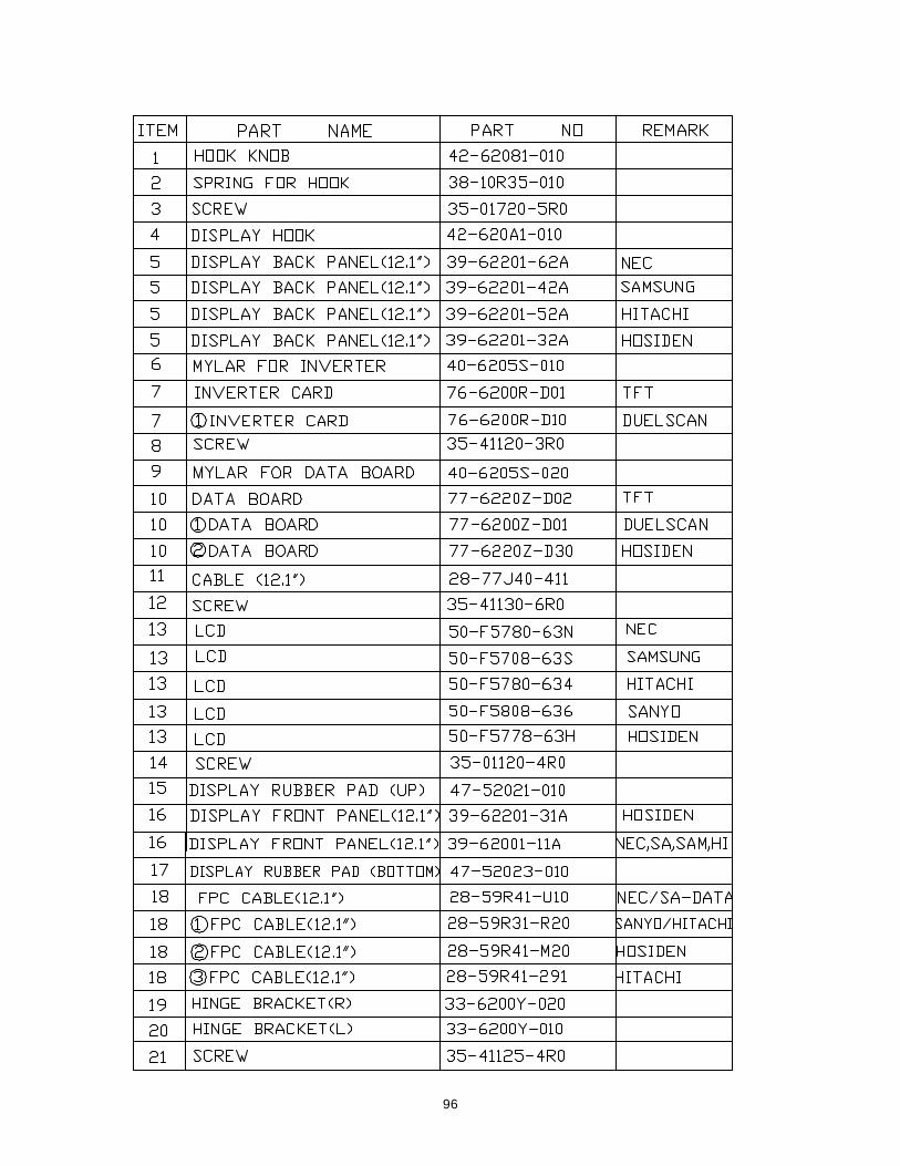
96
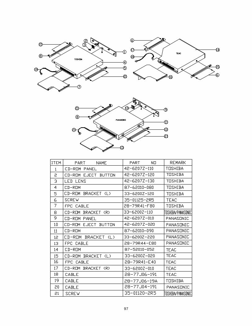
97
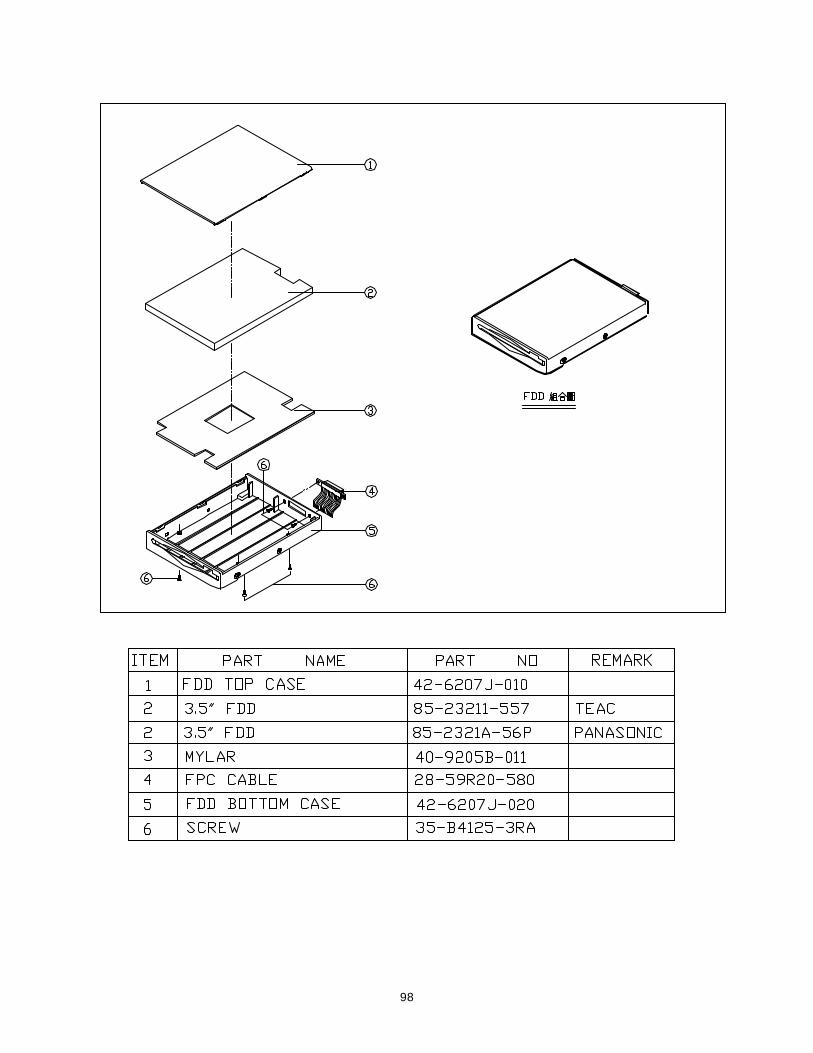
98
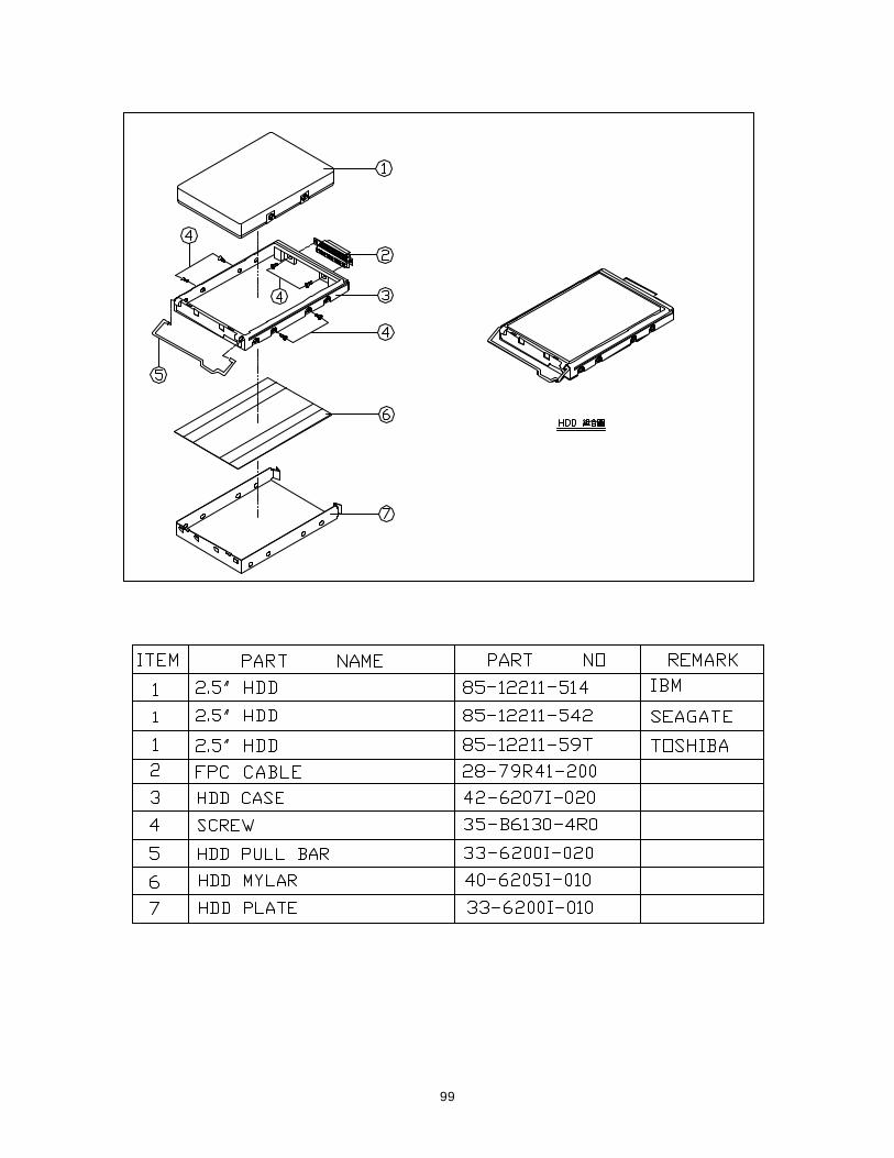
99
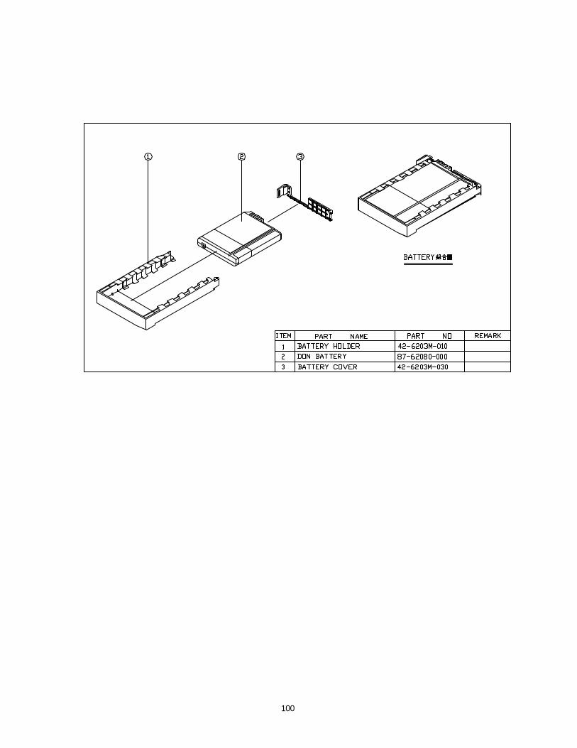
100