MODEL 485 - Triangle Universities Nuclear · PDF fileModel 485. Each feature is described in...
32
MODEL 485 AUTORANGING PICOAMMETER QUICK REFERENCE GUIDE
Transcript of MODEL 485 - Triangle Universities Nuclear · PDF fileModel 485. Each feature is described in...

MODEL 485 AUTORANGING PICOAMMETER
QUICK REFERENCE GUIDE
INTRODUCTION
This reference and programming guide contains condensed specifica- tions and information which describes the various features of the Model 485. Each feature is described in three segments of informa- tion. The first segment describes the features. The second segment gives an exact procedure on how to use the feature. The third seg- ment gives application examples. These segments are brief, but the information presented in this format is designed for a quick reference of the Model 485 features and functions. Refer to the Model 485 In- struction Manual for complete information and essential safety infor- mation.
With the Model 4853 IEEE-488 interface installed, the Model 485 can be controlled over the IEEE-488 bus. This booklet also contains infor- mation concerning Model 485 bus operation. Several example pro- grams using some commonly used controllers are outlined to get the Model 485/4853 “up and running”.
CONTENTS
CONDENSED SPECIFICATIONS .......................... 2 MODEL485 FEATURES ................................... 5 IEEE-488 PROGRAMMING.. ............................. 13 PROGRAMS ............................................ 18
IBM-PCorXTPersonalComputer.. ....................... 19 (Keithley Model 8573 Interface) APPLE II (Apple Interface) ............................... 21 HP-85 ................................................. 22 HP-9825A.. ........................................... 23 HP-9816 ............................................... 24 HP-9845B.. ........................................... 25 TEK4052 .............................................. 26 DECLSIll.. ......................... ___. .......... _.- 27 PETlCBM2001 ........................................ 29 EH 7000 Computer ..................................... 30
01984. Keithley Instruments, Inc. Cleveland, Ohio, U.S.A.
Document Number: 485903-OlA
1
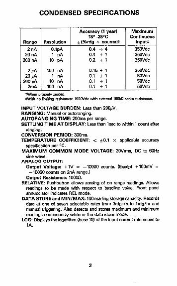
CONDENSED SPECIFICATIONS
Range
2nA 20 nA
2OilnA
J Resolution
O.lpA 1 PA
10 pA
100 nA 1llA
10 nA 100 nA
Accuracy (1 year) Maximum 18O -2WC Continuous
*(%rdg + countsIt InputS
0.4 + 4 35OVdc 0.4 -t 1 35OVdc 0.2 + 1 35OVdc
0.15 + 1 35OVdc 0.1 +1 5OVdc 0.1 +1 5OVdc 0.1 +1 5OVdc 1
W&h no limitiw resistance: 1OOOVdc with external lOOk series resistance.
INPUT VOLTAGE BURDEN: Less than 2OOhV. RANGING: Manual or autoranging. AUTORANGING TIME: 2COms per range. SElTLING TIME AT DISPLAY: Less than lsec to within 1 cuunt after
ranging. CONVERSION PERIOD: 300ms. TEMPERATURE COEFFICIENT: -z f0.1 x applicable accuracy
specification per T. MAXIMUM COMMON MODE VOLTAGE: BOVrms, DC to 60Hz
sine wave. ANALOG OUTPUT:
Output Voltage: +lV, = -10000 counts. (Except +lOOmV = -1OoM) wunts on 2nA range.)
Output Resistance: 1OOOQ. RELATIVE: Pushbutton allows zeroing of on range readings. Allows
readings to be made with respect to baseline value. Front panel annunciator indicates REL mode.
DATA STORE and MINIMAX: 100 reading storage capacity. Records date at one of seven selectable rates from Brdgs/s to lrdg/hr and manual triggering. Also detects and stores maximum and minimum readings continuously while in the data store mode.
LOG: Displays the logarithm (base 10) of the input current referenced to 1A.
2

SAFETY SYMBOLS AND TERMS
The ayrnboj Q I on the instrument denotes that user should refer to
the operating section in the Model 455 Instruction Manual.
The WARNING used in this guide explains dangers that could result in personal injury or death.
SAFETY PRECAUTIONS
1. Before operation, ground the instrument through a properly earth grounded power receptacle.
2. Before servicing, disconnect the instrument from the power line, all other equipment and consult the Model 455 Instruction Manual.
3. Do not touch the input terminal while the instrument is turned on or connacted to any other tast equipment. Common mode voltage may be prasent.
3

DISPLAY ANNUNCIATORS
the fol\owing annunciators are displayA on the LCD Kiquid Crystal Display1
AUTO-Indicates that the h+nfel485 is in the autorange mode. REL--lnticates that the relative mode isselecttxl. The reading is r&t& to some previous reading. LOG-Log mode reading is directly in log (base 101. SO-Indicates that the data store and minimax hold function is run- ning. Displayed raadjng is present input. RCL-Indicates that the displayed reading is recalled data. BAT-Indicates that the battery requires recharghg (operates only if the battery pack option Model 1758, is instaliedl. ZERO CHECK-Indicates that the Model 485 is in the zero check mode. Input impedance changes when in the zero check mode. nA, & or mA-Nanoamps, microamps or milliamps selected. Read measurement directly from the display. (e.g. 1.2345fll RMT--(Remote) Model 485 is being controlled over the IEEE-488 bus (Model 4853 installed). CAL-Indicates that the Model 435 is in the calibration mode.
4
MODEL 485 FEATURES
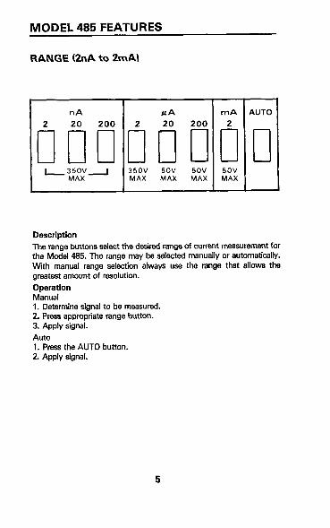
RANGE t2nA to 2mAl
I z&v I 35ov 5ov 5ov 5ov MAX MAX MAX MAX
Description
The range buttons se&t the desired range of current measurement for the Model 485. The range may’ be selected manually or automatically. With manual range selection always use the range that allows the greatest amount of resolution.
Operation Manual 1. Determine signal to be measured. 2. Press appmpriate range button. 3. Apply signal.
Auto 1. Press the AUTO button. 2. Apply signal.
5
ZERO CHECK
DesctiptIon
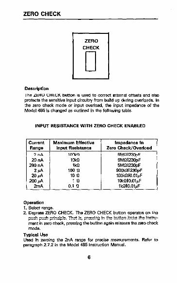
The ZERO CHECK button is used to correct interna ofFsets and also protects the sensitive input circuitry from build up during overloads. In the zero check mode or input overload, the input impedance of the Modal 495 is changed as outlined in the following table.
INPUT RESISTANCE WITH ZERO CHECK ENABLED
Current Maximum Effective Ranae lmut Resistance
2nA 1 1GMl
Impedance In Zero Check/Overload
9MWX3IpF
1. Select range. 2. Depress ZEFtO CHECK. The ZERO CHECK button operatas on the
push-push principle. That is, pressing in the button locks the instru- ment in zero check, pressing the button again releases the zero check mode.
Typical Use Used in zeroing the 2nA range for precise measurements. Refer to paragraph 2.72 in the Model 495 Instruction Manual.
6

REL (Relative Function)
REL
I
Description The relative function serves as a means of baseline suppression allowing a stored offset value to be subtracted from subsequent readings. When the REL button is pressed, the instrument stores the baseline reading with the next conversion. All subsequent readings represent the di- ferences between the applied signal level and the stored baseline. The stored baseline can be as small as the resolution of the instrument will allow or as large as full range.
It is important to note that the REL function reduces the dynamic range of measurements by that level (stored baseline). For example: assume that the REL level is + Id and the Model 495 is manually set to the w range. The maximum positive displayed reading, before overranging, would be + 0.9999& This is because the A/D converter would be see- ing + 1.9999fi to + 0.9999fi (2.999&A) as compared to the normal -1.9999fi to + 1.9999d (3.9998fi). Actually, the dynamic range is reduced by lfi or 10,000 counts. The effects on dynamic range can be reduced by selecting e higher range or using autorange.
Operation 1. Select measurement mode and range. For example: normal measure-
ment mode and the w range. 2. Press REL. The display reads zero. 3. The value that appeared on the display is now the stored offset.
Typical Use 1. Nulling out external source offset (e.g. calibrator offset). 2. Nulling out desired levels of offset (e.g. electrode dark current of
phototube).
7

LOG (Log Function)
Description The log function gives the log (base 101 of the measured input current referenced to 1A. Log can be used to make any current level the 0.0 (zero) point for log measurements. This can be done by selecting autorange and log. Then measuring the desired current that is to be the 0.0 [zero) point. The logarithm is taken on the absolute value of the measurement so that both positive and negative currents can be displayed as e log. Press the REL button and the display wiil read 0.0 (zero). The measured current is now the 0.0 (zero) point for the log function. The mathematical equation for the log function is shown as follows:
Input Display = Log -
I I 1 Amp
Operation (referenced to IA) 1. Select the auto range mode. 2 Apply the source. 3. Press the LOG button. The LOG annunciator on the display turns on. 4. Take the log reading from the display.
Typical Use 1. For use in measuring e wide range of current. Nuclear reactors have
various outputs of current that could be compressed (in readings on- ly) by using the log function.
2 Measuring the current output of a phototube. REL can be used to nu[l the dark current of the phototube.

DATA STORE (100 Point Data Store1
Description The 100 point data store function serves to save up to 100 points of data at the rate of one of six selectable rates from every reading (3 per second) to one reading per hour. Also, manual data entry is available (RN. This feature is useful in applications where data is required to be logged over a period of time.
Operation 1. Connect desired measurement configuration to the Model 485. 2. Select rate of storage and begin data store:
A. Press and hold in the STO/CLR button. 6. The rates are scrolled on the display. Tithe rates are described
below). C. Release the STWCLR button when the desired rate is displayed. D. The ST0 annunciator turns on indicating that the data is being
stored at the selected rate.
Typical Use 1. Saving data points of current drift of a low leakage device such as e
FEr. 2. Monitoring and saving current levels that fluctuate over a period of
time. r = 0 (every reading) r = 1 (1 reading per second) r = 2 (1 reading per 10 seconds) r = 3 I1 reading per minute) r = 4 I1 reading per 10 minutes) r = 5 (1 reading per hour) T = S (every time STOKLR is pressed)

STO/CLR (Store end Clear Function) Description The STOKLR button is an internal part of the data store function. The button has several functions that are listad as follows: 1. Starts the data store operation. 2. Turns off the data store operation. 3. Selects the storage rate. 4. In the R6 data rate mode the STOKLR button (when pressed) trlg-
gers the Model 485 to store a reading. 5. In the talk only mode, the STOKLR button selects the talk rate. The
store mode must be disabled for this function.
Operation 1. Press the STOKLR button to start the data store operation ISTO an-
nunciator on the display is turn on). At this point the Model 465 starts storing readings.
2. Hold in the STOKLR button to select the storage rate. The rates are scmlled on the display. Release the STOlCLR button when the desired rate is displayed.
3. Press the STOKLR button to stop the data store operation. All data is retained until e new store cycle has commenced.
4. When in the R6 data rate mode, prass the STOKLR button each time a reading is to be stored. This data rate mode is used for custom rate data storage.
5. Using the IEEE interface the STOKLR button can be used to select the talk rate. Refer to page 17.
10

RCL (Recall Function of DATA STORE)
Description The RCL button is used to retrieve data that has bean stored using the store/clear function.
Operation 1. Press and hold in the RCL button. The display scrolls through the
data points and minimum/maximum readings. The first data point displayed is the last stored reading. The next two data points are the HI and LO readings made during that store cycle. Notice that the longer the RCL button is held in the faster the data points scroll on the display.
2. Release the RCL button at the desired data point and note the reading on the display. The data pointer can be incremented by steps of one by momentarily holding in the RCL button.
3. Turn off the data store by pressing the STO/CLR button. All stored data is retained until a new store cycle has commenced.
MidMax HOLD Description The minimum/maximum hold feature detects and holds the highest and lowest readings while in the data store mode. This action is independent of the storage rate and runs at a rate of three readings per second. This function works in conjunction with the data store mode. The minimum and maximum readings are continuously updated while in the data store mode.
Operation 1. Use the data store mode to save a number of readings. 2 Press and hold in the RCL button. The display scrolls through the
data points and the minimumlmaxlmum points. The first data point displayed is the last data point that was stored. The next two data points are the maximum and minimum readings made during that store cycle.
3. Release the RCL button at the desired data point (min, max or nomral data point) and note the reading on the display. The data pointer can be incremented by steps of one by momentarily holding in the RCL button.
Typical Use Save up to 100 points of output current data along with the minimum and maximum readings of 1pA source that needs to be verified for calibration.
11
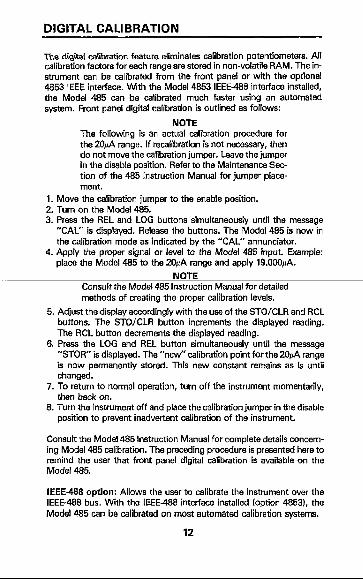
DIGITAL CALIBRATION
~ha diiitat calibration feature eliminates calibration potentiometers. All calibration factors for each range are stored in non-volatile RAM;The rn- strument can be calibrated from the front panel or with the optional 4353 IEEE interface. With the Model 4653 IEEE-488 interface installed, the Model 465 can be calibrated much faster using an automated system. Front panel digital calibration is outlined as follows:
NOTE The following is an actual calibration procedure for the 2Ofi range. If recalibration is not necessary, then do not move the calibration jumper. Leave the jumper in the disable position. Refer to the Maintenance Sec- tion of the 465 Instruction Manual for jumper place- ment.
1. Move the calibration jumper to the enable position. 2. Turn on the Model 465. 3. Press the REL and LOG buttons simultaneously until the message
“CAL” is displayed. Release the buttons. The Model 465 is now in the calibration mode as indicated by the “CAL” annunciator.
4. Apply the proper signal or level to the Model 465 input. Example: place the Model 465 to the 2Ofi range and apply 19.066~.
NOTE Consult the Model 465 Instruction Manual for detailed methods of creating the proper calibration levels.
5. Adjust the display accordingly with the usa of the STOKLR and RCL buttons. The STOKLR button increments the displayed reading. The RCL button decrements the displayed reading.
6. Press the LOG and REL button simultaneously until the massage “STOR” is displayed. The “new” calibration point for the 2&A range is now permanently stored. This new constant remains as is until changad.
7. To return to normal operation, turn off the instrument momentarily, then back on.
8. Turn the instrument off and place the calibration jumper in the disable position to prevent inadvertent calibration of the instrument.
Consult the Model 465 Instruction Manual for complete details concern- ing Model 465 calibration. The preceding procedure is presented here to remind the user that front panel digital calibration is available on the Model 465.
IEEE-468 option: Allows the user to calibrate the instrument over the IEEE-468 bus. With the IEEE48 interface installed (option 4653). the Model 465 can be calibrated on most automated calibration systems.
12

IEEE-488 PROGRAMMING
Tha K&hlay Model 485 has an optional IEEE-488 interfaca (Model 4853) which can be included with the instrument or added later. Inclusion of the interface option is apparent by the connector and address switch at the rear panel. The field installable option kit in- cludes a replacement top cover with appropriate access openings on the rear panel. The following lists all the commands available to the Model 485.
RANGE:
LOG:
RELATIVE:
ZERO CHECK:
TRIGGER:
EOI:
STORE:
DIGITAL CALIBRATION:
SRQ:
RO = Auto Range (RO ignored in calibration mode)
Rl = 2nA R2 = 20 nA R3 = 200 nA R4= Z/UI R5 = 20/A R6=266d R7= 2mA W=Off Dl = On M=Off 21 = On CO=Off Cl = On To = Continuous on Talk Tl = One-shot on Talk T2 = Continuous on GET T3 = Oneshot on GET T4 = Continuous on “X” T6 = One-shot on “X” KO = EOI is transmitted on the last byte
out. Kl = EOI is not transmitted. L6 = Store Calibration Constants
V+n.nnnnE+nn n = Calibration Value Mnnn nnn = 0 to 255 (base 10) MO = Clear SRQ data mask Ml = Reading Overflow ME = Reading Done M9 = Reading Done or Reading Overflow
13
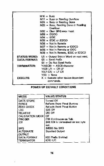
Ml6 = Busy Ml7 = Busy or Reading Overflow M24 = Busy or Reading Done M25 = Busy, Reading Done or Reading
ovemow P.432 = Clear SRQ Errol mask M33 = IDDCQ M34 = IDDC M35 = IDDC or IDDCO M36 = Not in Remote M37 = Not in Remote or IDDCO M33 = Not in Remota or IDDC M39 = Not in Remote, IDDC or IDDCO
STATUS WORD: UO = Output Status Word on next read. DATA FORMAT: GO = Send Prefuc
Gl = Do Not Send Prefix TERMINATOR: Y(ASCII) = ASCII character
Y(CR LF) = CR LF YiLF CR) = LF CR Y(X) = None
EXECUTE: X = Execute other device-dependent commands.
POWER UP DEFAULT CONDITIONS
LOG REIATNE CALIBRATION MOM TRIGGEFI EQI
DATA FORMAT
VALUE/STATUS
Turned Qff Reflects Front Panel Buttons Reflects Front Panel Button Do) off m off w (TO) Continuous on Talk (KC0 EOI is tranm-iti cm last byte out. (MOOO) No SRQ Standard Output
(GO1 Prefix Enabled (CR) ILFI
14

MODEL 4953 PRIMARY ADDRESS SWITCH SET AT 22 (10110)
TALKER ONLY (TO) MODE
:1pljijJpg 1 ADDRESSABLE
MODE
DATA FORMAT: (Reading)
NDCA * 1 .2345 E-9 CR LF
1 ~iiiti&.%@
N = Normal 0 = Overflow C = Zero Check Z = Relative
15
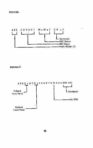
STATUS:
485 CDRZKT MdMeY CR LF
r 7YzJLsIgdl,D.
DEFAULT:
4 8 5 C x D 0 R x Z 0 K 0 T 0 M 0 0 0 (CR) ILFI
R.sfk?cts Front Panel
Reflects . 1 Front Panel
16

Talk Only Operation Description The talk oniy mode may be used to send data to a listen only device such as a printer. When the Model 465 is in the talk only mode, it ignores commands given over the bus. The talk only mode is enabled by placing the TOlADDRSSABLE switch in the TO position and then cycling power to the instrument. The default talk rate is three readings per se- cond (every reading). However, a different talk rate can be selected by performing the following procedure.
Operation 1. Enable the talk only mode. Cycle power to the instrument. 2. Press and hold in the STOKLR button. The following talk rates scroll
on the display: r = 0 (every reading) r = 1 (1 reading per second) r = 2 (1 reading per 10 seconds) r = 3 (1 reading per minute) r = 4 (1 reading per 10 minutes) r = 5 (1 reading per hour) r = 6 (1 reading per every time STOKLR is pressed)
3. Release the STOlCLR button when the desired talk rate is displayed. At this point the ST0 annunciator appears on the display indicating that the instrument is talking at the selected rate.
4. Turn off the data store operation by pressing the STOKLR button. Notice that the ST0 annunciator turns off.
,
NOTE The instrument remains in the selected talk rate until a new rate is selected or power is cycled.
17

PROGRAMS
The fallowing programs are designed to be a simple aid to the war. They are not intended to suit specific needs. Detailed programming in- formation can be found in the manual.
These programs display one readhg at the output of the controller. The program provides an ASCII string variable output of the form:
NDCA + O.DoOO+O CR LF
The note at the end of each program indicates modifications to provide a numeric variable (A) in exponential form:
+o.ooao+o
18
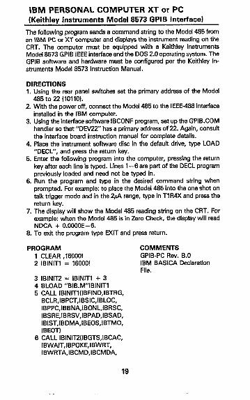
IBM PERSONAL COMPUTER XT or PC (Keithley Instruments Model 8573 GPIB Interface)
The following program sends a command string to the Model 485 from an \BM PC or XT computer and displays the instrument reading on the CRT. The computer must be equipped with a Keithley Instruments Model 8573 GPIB IEEE interface and the DOS 20 operating system. The GPIB software and hardware must be configured per the Keithley In- struments Model 8573 Instruction Manual.
DIRECTIONS 1. Using the rear panel switches set the primary address of the Model
485 to 22 (10110). 2 Wti the power off, connect the Model 485 to the IEEE-488 interface
installed in the IBM computer. 3. Using the interface software IBCONF program, set up the GPIB.COM
handler so that “DEV22” has a primary address of 22 Again, consult the interface board instruction manual for complete details.
4. Place the instrument software disc in the default drive, type LOAD “DECL”, and press the return key.
5. Enter the following program into the computer, pressing the return key after each line is typed. Lines l-6 are part of the DECL program previously loaded and naed not be typed in.
6. Run the program and type in the desired command string when prompted. For example: to place the Modal 485 into the one shot on talk trigger mode and in the &A range, type in Tl R4X and press the return key.
7. The display will show the Model 485 reading string on the CRT. For example: when the Model 485 is in Zero Check, the display will read NDCA + O.OOOOE-6.
8. To exit the program type EXIT and press return.
PROGRAM 1 CLEAR ,160OOl 2 IBlNlTl = 160001
3 IBINlT2 = IBlNlTl + 3 4 BLOAD “BIB.M”IBINITl 5 CALL IBINITl(IBFIND,IBTRG,
BCLR,IBPCT,IBSIC,IBLOC, IBPPC,IBBNA,IBONL,IBRSC, IBSRE,IBRSV,IBPAD,IBSAD, IBIST,IBDMA,IBEOS,IBTMO, IBEOTI
6 CALL IBINITZ(lBGTS,IBCAC, IBWAIT,IBPOKE,IBWRT, IBWRTA,IBCMD,IBCMDA,
COMMENTS GPIB-PC Rev. B.0 IBM BASICA Declaration File.
19

tBRD,WRDA,tBSTOPP.tBRPP. IBRSP,IBDIAG,IBXTRC. IBSTA%,IBERR%,IBCNT%f
10 CLS 20 NA$=“GfIB9”:CALL IBFIND
(NAS,BRW%) Find the board number.
30 NAS = “DEVW:CALL IBFIND (NAS,M485%)
Fktd the 485 number.
40 V% =22CALL IBPAD Wl85%,V%1
50 V% = 1:CALL IBSRE (BRDO%,V%)
Change to primary address 22. Set REN true.
60 lNPLTT”COMMAND”;CMDS
70 IF CMDS=“EXIT” THEN 140
60 IF CMD$=“” THEN 60
90 CALL IBWRT(M485%,CMDS)
100 RDS=SPACE$(BO) 105 CALL IBRD (M485%, RD91 110 RDS= LEFWRDS,IBCNT%) 120 PRINT RDS
130 GOT0 120 140 V% =&CALL IBONL
fM485%,V%)
Prompt for wmmand string. See if program is to be halted. If null command string go back and get another. Address 485 to listen and sand command string. Assign reading input buffer.
Trim strfng to proper size Display the reading on the CRT Repeat Close the board file.
150 CALL IBONLlM485%,V%l 160 END
Close the instrument fife.
NOTE: Lines l-6 of this program need not be typed in. They are con- tained on the Roppy disc. When the command LOAD”DECL” is entered, these lines are already there.
NOTE: If conversion to numeric variable is desired, change lines 110 and 120 as follows:
110 RD=VALtMIDStRDS,5,14H 120 PRINT RD
20

APPLE II (APPLE Interface]
The following program obtains one reading from the Model 485 Picoam- meter and displays the reading on th APPLE II screen, using an APPLE IEEE-488 interface.
DIRECTIONS 1. Using the rear panel switches, set the primary address of the Model
485 to 22 (10110). 2. Connect the Model 485 to the APPLE II and APPLE IEEE-488 inter-
face. 3. Enter the following program using the RETURN key after each line. 4. Type in RUN and depress the RETURN key. 5. The display will read “TEST SETUP”. 8. To program the Model 485 to the w range and take a reading type
in R4TlX and depress the RETURN key. 7. The disolav will read NDCA + O.OOOOE-6 when the Model 485 is in
zero ctL?cic.
PROGRAM 10 DIM A$(2O),BS(20) 20 ZS = CHRS(28) 30 INPUYTEST SETUP?“;B$
40 PR#3 50 IN#3 60 PRINT “RA” 70 PRINT “W-i%“~Z$~B$ r , 80 PRINT “LFl” 90 PRINT “RDV”.Z$.:INPUT , r ” ‘I;
AS 100 PRINT “UT’ 110 PR#O 120 IN#O 130 PRINT A$ 140 GO TO 30
COMMENTS Dimension data string. Terminator Enter programming command. Example: 2& range = R4TlX Send output to IEEE bus. Get input from IEEE bus. Turn remote on. Write BS to 485. Linefeed On Read data from 485.
Send output to CRT. Get input from keyboard.
Repeat
NOTE: If conversion to numeric variable is needed, add the following:
134 A=VAL(MIDS(AS,5,111) 136 PRINT A
21
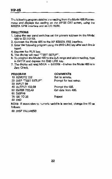
HP-85
The following program obtains ooereadingfromthe W 485 Piwam- meter and displays the reading on the HP85 CRT scr~-%, using the 62937A GPIB interface and an I/O ROM.
DIRECTIONS 1. Using the rear panel awitches set the primary address on the Model
465 to 22 (10110~. 2. Connect the Model 465 to the HP 62Q37A IEEE interface. 3. Enter the following program using the END LINE k8yaft8r each lineis
4. Depress the RUN key. 5. The display will read “TEST SETUP”. 6. To program the Model 465 to the 2@ range and take a reading, type
in R4TlX and depress the END LINE key. 7. The display will read NDCA + O.OOOOE--6when the Model 485 is in
Zero Check.
PROGRAM COMMENTS 10 REMOTE 722 Set to remote. 20 DISP ‘TEST SETUP” Prompt for test setup. 30 INPUT ES 40 OUTPUT722;B$ Prompt the 465. 50 EMER 722;A$ Get data from 485. 60 DISPAS 70 GO TO 20 Repeat 80 END
NOTE: If mnvetion IO numeric variable is needed, change line 60 m follows:
60 DISP VALLASWI
22
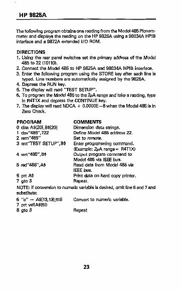
HP 9825A
The following program obtains one reading from the Model 485 Picoam- meter and displays the reading on the HP 9825A using a 98034A HPIB interface and a 9872A extended I/O ROM.
DlRECTfONS 1. Using the rear panel switches set the primary address of the Model
485 to 22 l101101. .-- - ..-..-,. 2. Connect the Model 485 to HP 9825A and 98034A HPIB interface. 3. Enter the following program using the STORE key after each line is
typed. Line numbers are automatically assigned by the 9825A. 4. Depress the RUN key. 5. The display will read “TEST SETUP”. 6. To program the Model 485 to the w range and tak8 a reading, type
in R4TlX and depress the CONTINUE key. 7. The displav will read NDCA + O.OOOOE-6 when the Model 485 is in
Zero Check.
PROGRAM 0 dim A$L!O~,B$I201 1 dev”485”,722 2 rem”485” 3 ent”TEST SETUP”,B$
4 wrt”485”,BS
5 red’WW,A$
6 prtA$ 7 gto3
COMMENTS Dimension data strings. Define Model 485 address 22. Set to remote. Enter programming command. (Example: w range = R4TlX) Output program command to Model 485 via IEEE bus. Read data from Model 485 via IEEE bus. Print data on hard copy printer. Repeat.
NOTE: If conversion to numeric variable is desired, omit line 6 and 7 and substitute: 8 “e” - A$[13,131;flt5 Convert to numeric variable. 7 prt valtASf51) 8 gto3 Repeat
23
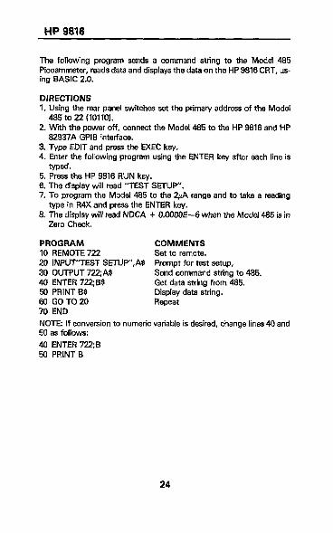
HP 9818
The following program sends a command string to the Model 485 Piwammeter, reads data and displays the data on the HP 9816 CRT, us- ing BASIC 2.0.
DIRECTIONS 1. Using the rear panel switches set the primary address of the Model
485 to 22 (10110). 2. Wnh the power off, connect the Model 485 to the HP 9816 and HP
82937A GPIB interface. 3. Type EDIT and press the EXEC key. 4. Enter the following program using the ENTER key after each line is
8. The display will r&d NDCA Zero Check.
PROGRAM 10 REMOTE 722 20 INPUT’I-EST SETUP” A$
’ 30 OUTPUT 722; AS 40 ENTER 722;B4 50 PRINT BS 60 GOT020 70 END
5. Press the HP 9815 RUN key. 6. The display will read ‘TEST SETUP”. 7. To program the Model 485 to the &A range and to take a reading
tvDe in R4X and press the ENTER kev. t O.OOObE-6 when the Model 485 is in
COMMENTS Set to remote. Prompt for test setup, Send command string to 485. Get data string from 485. Display data string. Repeat
NOTE: If mnversion to numeric variable is desired, change lines 40 and 50 as follows:
40 ENTER 722;B 50 PRtNTB
24
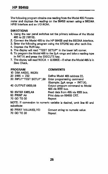
HP 98458
The following program obtains one reading from the Model 485 Picoam- meter and displays the reading on the 98458 screen using a 98034A HPIB interface and an I/O ROM.
DIRECTIONS 1. Using the rear panel switches set the primary address of the Model
485 to 22 IlOllO). 2. Connect the Model 485 to the HP 98458 and the 98034A interface. 3. Enter the following program using the STORE key after each line. 4. Depress the RUN key. 5. The display will read “TEST SETUP” in the lower left comer. 6. To program the Model 485 to the 2~& range and take a reading type
in R4TlX and press the EXECUTE key. 7. The display will read NDCA + 0.0000E-6 when the Model 485 is in
Zero Check.
PROGRAM COMMENTS 10 DIM ASI201, B$lZOl 20 E485 = 722 Define Model 485 address 22. 30 INPLF’TEST SEWP”,B$ Enter programming command
40 OUTPUT E485;B$ (Example: 2$1 rang8 = R4TlX). Output program command to Model 485 via IEEE bus.
50 ENTER W35;A9 Read data from 485 via IEEE bus. 60 PRINT A$ Print data on 98458 CRT. 70 GO TO 30 Repeat
NOTE: If conversion to numeric variable is desired, omit line 60 and substitute:
60 PRINT VAL(A$IB,lll) Convert string to numeric value. 70 GO TO 30 Repeat
25

TEK 4052
The f&owing program obtains one reading from the Model 485 Picoam- meter and displays the reading on the TEK 4052 graphics terminal, with a 4051 GPIB interface.
DIRECTIONS 1. Using the tear panel swltchas set the primary address of the Model
485 to 22 (101IOi. 2 Connect the Model 485 to the TEK 4051 IEEE interface. 3. Enter the following program using the RETURN key after each line. 4. Type in RUN. 5. The display will read “TEST SETUP”. 6. To program the Model 485 to the 2+A range and take a reading, type
in R4TlX and press the RETURN key. 7. The display wiil read NDCA f O.OlWOE-6 when the Model 485 is in
Zero Check.
PROGRAM COMMENTS 5 PRINT @ 37,o: IO, 255, I3
IO PRINT “TEST SETUP” Prompt for the test setup. 20 PRINT B$ 30 PRINT @ 22: BS Program the Model 485. 40 INPUT % 22: AS Get data from the Model 485. 50 PRINT AS 60 GOT010 Repeat
NOTE: If conversion to numeric variable is desired, change lines 40 and !XtO:
40 INPUT % 22: A 80 PRINT A
26

DEC LSI 11
The following program obtains one reading from the Model 485 Picoam- meter and displays the reading on the DEC LSI 11 microcomputer CRT terminal. The LSl 11 must be confiaured with 16k words of RAM and an IBV 11 IEEE interface. The softw&e must be configured with IB soft- ware as well as the FORTRAN and the RT 11 operating system.
DIRECTIONS 1. Using the rear panel switches set the primary address on the Model
485 to 22 f10110). 2. Connect the Model 485 to the IBV 11 IEEE cable. 3. Enter the following program, using the editor under RT 11 and the
name IPHILD. 4. Compile using the fortran compiler as follows: FORTRAN IPHILD. 5. Link with the svstem and IB libraries as follows: LINK IPHILD,IBLIB. 6. Type RUN IPHILD and depress the RETURN key. 7. The disolav will read “ENTER ADDRESS”. 8. Type in’iand depress the RETURN key. 9. The display will read “TEST SETUP”.
10. To program the Model 485 to the &A range and take a reading, type in R4TlX and depress the RETURN key.
11. The display will read NDCA + O.OOOOE-6 when the Model 485 is in Zero Check.
PROGRAM INTEGER*2 PRIADR LOGlCAL*1MSGf80),INPUT63O) DO 2 I = 1,lO CALL IBSTERfI,O)
2 CONTINUE CALL IBSTER (15,5) CALL IBTlMO (120)
CALL IBTERM (“10) CALL IBREN
4 TYPE5 5 FORMAT flX,‘ENTER
ADDRESS’,81 ACCEPT 10, PRIADR
10 FORMAT (2141 12 TYPE 15 15 FORMAT flX,‘TEST SETUP’,$)
CALL GETSTR (5,MSG,72l CALL IBSEOI (MSG.-l PRIADR)
COMMENTS
ITurn off IB errors.
IAllow 5 errors 16’s. IAllow 1 second bus timeout.
IS& LF as terminator. ITurn remote on.
llnput the address 22.
[Prompt for the test setup. IGet the test setup. [Program the 485.
27

18 I = IBRECV (\NPUT,BO.PRlADR, INPUT II + 1) = 0 CALL PUTSTR 0 \NPUT CALL IBUNT ’ ’
‘07
GOT012 END
Wntalk the 485. IRepeat
28

PET/CBM 2001
The following program obtains one reading from the Model 465 Picoam- mater and displays the reading on the PET/CBM 2001 screen.
DIRECTIONS 1. Using the rear panel switches sat the primary address of the Model
465 to 22 f10110). 2. Connect the Model 465 to the PET/CBM 2001 IEEE interface. 3. Enter the following program using the RETLtRN key after each line. 4. Type RUN and depress the RETURN key. 5. The display will read “TEST SETUP”. 6. To program the Model 465 to the 2& range and take e reading, type
in R4TlX and depress the RETURN key. 7. The display will read NDCA + O.OOOOE-6 when the Model 485 is in
Zero Check.
PROGRAM 10 OPEN 622 20 INPUT “TEST SETUp”;BS
30 PRINT&B$ 40 INPUT#G,A$
50 IFST = 2THEN40 60 PRINT A$ 70 GOT020
NOTE: If conversion to numeric the following:
70 A = VAL(MID$fAS,5,15))
60 PRINT “A=” .A ’ 90 GOT020
COMMENTS Open file 6, primary address 22. Enter programming command. (Example: w range = R4TlX). Output to IEEE bus. Read data from Model 485 via IEEE bus. If time out, input again. Print data. Repeat
: variable is desired, omit line 70 and type
Convert to numerfc variable.
Repeat
29
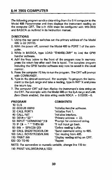
E-H 7000 COMPUTER
The following program sends a data string from the E-H computer to the Modei 485 Picoammeter and then displays the instrument reading on the computer CRT. The hH 7000 must be configured with MS-DOS and BASICA as outlined in its instruction manual.
DIRECTIONS 1. Using ffie rear panel switches set the primary address of the Model
485 to 22 (10110). 2. With the power off, connect the Model 485 to PORT 1 of the com-
puter. 3. While in BASICA, type LOAD “EHE488.CMP” to Load the GPIB
handler software. 4. Add the lines below to the front of the program now [n memory;
press the return key after each line is typed. The complete program including the GPIB handler software may now be saved in the usual manner.
5. Press the computer F2 key to run the program. The CRT will prompt with COMMAND?.
6. TVpe in the desired command. For example: To program the instru- ment to the w range and take a reading, type in R4TIX and press the return key.
7. The computer CRT will then display the instrument’s data string on the CRT. For example: with the Model 485 on the w range and with Zero Check enabled, the data string reads NDCA f O.OOOOE-6.
PROGRAM COMMENTS 10 CLS 20 GOSUB 65010 ‘Initialize handler software. 30 CALL PORT1 ‘Initialize Port 1. 40 CALL INIT ‘Initialize interface. 50 DEV$=“22” ‘Primary address = 22. 60 INPUT “COMMAND’CG 70 IF C$ = ” ” THEN sd
‘Prompt for command string. ‘If null input go back.
80 INS = SPACES 120) ‘Define reading buffer. 90 CALL SNDSTRlDEVS,C$) ‘Send command string to 4135.
100 CALL RCVSTR(DEV$,INS) ‘Get reading from 485. 110 PRlNT INS ‘Display reading string on CRT. 120 GO TO 60 ‘Repeat
NOTE: For conversion to numeric variable, change line 110 to:
110 PRINT VALfMIDS(tN$,5,152))
30

Test Instrumentation Group 28775 Aurora Road /Cleveland, Ohio 44139