Model 4552 Purge-and-Trap Water/Soil Autosampler Operator ...aimanalytical.com/Manuals/O.I. Model...
162
Model 4552 Purge-and-Trap Water/Soil Autosampler Operator’s Manual 151 Graham Road · P.O. Box 9010 · College Station, Texas 77842-9010 Telephone (979) 690-1711 · FAX (979) 690-0440 · www.oico.com · [email protected]
Transcript of Model 4552 Purge-and-Trap Water/Soil Autosampler Operator ...aimanalytical.com/Manuals/O.I. Model...

Model 4552 Purge-and-Trap Water/Soil Autosampler
Operator’s Manual
151 Graham Road · P.O. Box 9010 · College Station, Texas 77842-9010Telephone (979) 690-1711 · FAX (979) 690-0440 · www.oico.com · [email protected]

Notice The information contained in this document may be revised without notice.
OI Analytical shall not be liable for errors contained herein or for incidental or consequential damages in connection with the furnishing, performance, or use of this material.
No part of this document may be reproduced, photocopied, or translated to another language without the prior written consent of OI Analytical.
Rev. 4.0 — February 2004
Agilent is a registered trademark of Agilent Corporation.
Cheminert and Valco are registered trademark of Valco Corporation.
Luer-Lok is a registered trademark of Becton-Dickinson Corporation.
Molex is a registered trademark of Molex Corporation.
PEEK is a registered trademark of Victrex PLC.
Shimadzu is a registered trademark of Shimadzu Corporation.
SoilVial is a trademark of Dynatech Precision Sampling, Inc.
Swagelok is a registered trademark of Crawford Fittings Company.
Teflon is registered trademark of E.I. DuPont de Nemours, Inc.
Tekmar is a registered trademark of Tekmar Corporation.
Varian is a registered trademark of Varian Associates, Inc.
Windows is a registered trademark of Microsoft Corporation,
OI Analytical Part Number 285007
Printed in the U.S.A.
Publication 07850204
Copyright 2004 OI Analytical
ii

Limited Warranty
OI Analytical warrants each Model 4552 Purge-and-Trap Water/Soil Autosampler against defects in materials and workmanship under normal use and service for a period of one year. Equipment installed by OI Analytical is warranted from the installation date. All other equipment is warranted from the ship date. If purchaser schedules or delays installation more than 90 days after delivery, then warranty period starts on the 91st day from date of shipment. This warranty extends only to the original purchaser. OI Analytical will, at its option, repair or replace equipment that proves defective during the warranty period, provided the equipment is returned to OI Analytical at the expense of the purchaser.
OI Analytical warrants consumables, columns, lamps, and high-temperature furnaces for 30 days (parts only) and does not make them available for coverage under extended warranties or service contracts.
This warranty shall not apply to defects originating from:• Improper maintenance or operation by purchaser.• Purchaser-supplied accessories or consumable.• Modification or misuse by purchaser.• Operation outside of the environmental and electrical products specifications.• Improper or inadequate site preparation.• Purchaser-induced contamination or leaks.
THE FOREGOING WARRANTY IS IN LIEU OF ALL OTHER WARRANTIES, EXPRESS OR IMPLIED, INCLUDING BUT NOT LIMITED TO ANY WARRANTY OF MERCHANTABILITY, FITNESS, OR ADEQUACY FOR ANY PARTICULAR PURPOSE OR USE. OI ANALYTICAL SHALL NOT BE LIABLE FOR ANY SPECIAL, INCIDENTAL, OR CONSEQUENTIAL DAMAGES, WHETHER IN CONTRACT, TORT, OR OTHERWISE.
Direct any service requests or questions to the OI Analytical Technical Support Department at (800) 336-1911 or (979) 690-1711.
iii

iv

Table of Contents
Notice .......................................................................................................................... iiLimited Warranty ....................................................................................................... iii
Chapter 1: Introduction.................................................................................. 1Operating Principles .....................................................................................................1Features ........................................................................................................................2Specifications ...............................................................................................................2
General Specifications .......................................................................................... 2Performance Specifications .................................................................................. 3Requirements ........................................................................................................ 3
Safety Information........................................................................................................4Operator Precautions ............................................................................................ 4General Precautions .............................................................................................. 4Compressed Gas Cylinder Precautions................................................................. 4Safety Symbols ..................................................................................................... 5
Chapter 2: Instrument Components ............................................................. 7Model 4552 Front View ...............................................................................................7Model 4552 Keypad .....................................................................................................8Model 4552 Back View................................................................................................9Model 4552 Interior View..........................................................................................10Sample Vial Types .....................................................................................................11
Chapter 3: Installation.................................................................................. 13Unpacking the Model 4552 ........................................................................................13
Packing the Model 4552 for Shipping ................................................................ 13Precautions During and After Installation..................................................................14Installing the Model 4552 ..........................................................................................15
Setting Up Electrical Connections...................................................................... 15Setting Up Gas Connections............................................................................... 15Setting Up The Reservoir Bottle......................................................................... 16Setting Up The Sample Tray .............................................................................. 16Installing the Optional Sample Tray Cooling..................................................... 18
Connecting to the Eclipse...........................................................................................18Installing the Four-Way Injection Valve on the Eclipse .................................... 18Installing the Purge Gas Lines on the Eclipse .................................................... 19Installing the Soil-Purge-Gas Transfer Line on the Eclipse ............................... 20Installing the Water Transfer Line on the Eclipse .............................................. 21Configuring the Eclipse ...................................................................................... 23
Connecting to the Model 4560 ...................................................................................25Installing the Thermocouple and Heater Cartridge ............................................ 25Installing the Soil-Purge-Gas Transfer Line on the Model 4560 ....................... 25Installing the Purge Gas Lines on the Model 4560............................................. 26Installing the Four-way Sample Valve on the Model 4560................................ 27Installing the Water Transfer Line on the Model 4560 ...................................... 28 Configuring the Model 4560 ............................................................................. 29
Connecting to the Tekmar 3000 .................................................................................29Installing the Four-Port Fitting on the Tekmar 3000.......................................... 29
v

Installing the Soil-Purge-Gas Transfer Line on the Tekmar 3000 ..................... 30Installing the Purge Gas Lines on the Tekmar 3000........................................... 32Installing the Water Transfer Line on the Tekmar 3000 .................................... 33 Configuring the Tekmar 3000 ........................................................................... 34
Connecting to the Tekmar 2000 .................................................................................34Installing the Four-Port Fitting on the Tekmar 2000.......................................... 34Installing the Soil-Purge-Gas Transfer Line on the Tekmar 2000 ..................... 35Installing the Purge Gas Lines on the Tekmar 2000........................................... 36Installing the Water Transfer Line on the Tekmar 2000 .................................... 37Configuring the Tekmar 2000 ............................................................................ 38
Adjusting Soil Helium Purge Gas Flow.....................................................................38
Chapter 4: Operation.................................................................................... 39Keypad and Screen Display .......................................................................................39Operating the Model 4552..........................................................................................39
Autosampling Procedure .................................................................................... 39Single Sample or Priority Run............................................................................ 40Manual Flush Sequence...................................................................................... 42Pausing and Stopping ......................................................................................... 44System Hold........................................................................................................ 44
Setting up a Method ...................................................................................................45Method Editing ................................................................................................. 45Sample Method Parameters ................................................................................ 45Blanks After Vial Editing ................................................................................... 49Method Programming Guidelines....................................................................... 50Equilibrium Count and Time .............................................................................. 52
Operating Sequence Steps..........................................................................................53Water Sample Sequence ..................................................................................... 53Soil Sample Sequence......................................................................................... 55Blank Sample Sequence ..................................................................................... 56
System Setup ..............................................................................................................57Front Park ........................................................................................................... 58System Status...................................................................................................... 58System Maintenance........................................................................................... 59Calibrating the System........................................................................................ 61
System Diagnostics ....................................................................................................71System Settings ..........................................................................................................73Systems Options.........................................................................................................77Method Table .............................................................................................................79
Chapter 5: Maintenance ............................................................................... 81Replacing the Needle Sparge or SoilVial Probe ........................................................81
Removing the Needle Sparge or SoilVial Probe ................................................ 81Installing the Needle Sparge or SoilVial Probe.................................................. 82
Replacing the Water Probe.........................................................................................83Removing the Water Probe................................................................................. 83Installing the Water Probe .................................................................................. 83
Cleaning the Soil-purge-gas Transfer Line Frit .........................................................84Replacing the Soil-purge-gas Transfer Line ..............................................................84
Removing the Soil-purge-gas Transfer Line ...................................................... 84Installing the Soil-purge-gas Transfer Line........................................................ 84
Replacing the Heated Upper-Soil Valve ....................................................................85
vi

Replacing the Water Line Screen...............................................................................85Replacing the Soil-purge-gas Needle.........................................................................85Installing the Internal Standard Vials.........................................................................86Cleaning the Vial Gripper ..........................................................................................86Checking the Helium Purge Gas Flow for Leaks.......................................................87Adjusting the Sample Stir Motor Speed.....................................................................88Cleaning the Drip Pan ................................................................................................88Cleaning or Replacing the Syringe Plunger O-ring ...................................................89Cleaning the Internal Standard Valve and Lines........................................................91
Chapter 6: Troubleshooting ........................................................................ 93
Chapter 7: Replacement Parts .................................................................... 97
Chapter 8: Cable Connections .................................................................. 105Connecting to the Eclipse or Model 4560 with an Agilent 6890N GC....................105Connecting to the Eclipse or Model 4560 with an Agilent 5890 or 6890 GC .........107Cable Pinouts............................................................................................................108
Model 4552 Remote I/O Connector Signal Pinouts ......................................... 111Connecting to the Tekmar 3000 with Any GC ........................................................112Connecting to the Tekmar 3000 with an Agilent 5890 GC......................................113Connecting to the Tekmar 3000 with a Varian 3400/3600 GC................................115Connecting to the Tekmar 3000 with an Agilent 5895/96/85/87/88/92...................119
Cable Connections ............................................................................................ 120Connecting to the Tekmar 3000 with an Agilent 5890/5889 with 5970/71/72........122Connecting to the Tekmar 3000 with an Agilent 6890/6850 ...................................124Connecting to the OI Analytical Eclipse/Model 4460/4560 with a Varian 3400/3600 GC ............................................................................................................................126Connecting to the OI Analytical Eclipse, Model 4560/4460 with an Agilent 5890, RTE Agilent 1000 Series GC/MS Software .....................................................................127Connecting to the Tekmar 3000 with a Varian 3800 GC.........................................129
Chapter 9: Assembly Diagrams ................................................................ 131Internal Standard Valve Assembly...........................................................................131Mixing Solenoids and 26-mL Syringe Assembly ....................................................132Vial Sample Station..................................................................................................132Probe Section and Interface/Transfer Line, Purge Gas Solenoid.............................133Inside Back Panel .....................................................................................................134Robotic Arm.............................................................................................................135
Chapter 10: Interconnection Diagram ...................................................... 137
Chapter 11: Flow Diagrams ....................................................................... 139
Index ............................................................................................................ 151
vii

viii

Chapter 1 Introduction
The Model 4552 Purge-and-Trap Water/Soil Autosampler automates sample handling procedures for purge-and-trap analysis of volatile organic compounds (VOCs) using current USEPA methods. It can be used for drinking water, wastewater, soil, and solids analysis. The Model 4552 operates as a standalone unit with the OI Analytical Model 4660 Eclipse, Model 4560, and other purge-and-trap sample concentrators.
The Model 4552 contains state-of-the-art XYZ-axis robotics. It uses a 51-position sample tray that handles both water or soil samples. An optional chiller cools the sample tray. The Model 4552’s unique grabber arm moves the sample vial to different positions that read the bar code (optional), identify the vial type, stir the sample, equilibrate to room temperature, and transfer the sample to the water or soil probe position. An optional Windows®-based software package enables remote Model 4552 operation from a personal computer (PC).
Operating Principles
The Model 4552 automates heated purge-and-trap analysis when running soil samples. Place the soil sample into a patented SoilVial™ or, if the Model 4552 is set up for needle sparging, a standard 40-mL VOA vial. Add a stir bar (optional), cap the vial with a low-bleed septum, and place the vial in the sample tray. The robotic arm transfers the vial to the vial identification position. The vial then moves into the heated chamber, where the Model 4552 adds water with one or both standards. The sample then purges directly onto the sample concentrator’s trap.
If running a water sample, place the sample in a 40-mL VOA vial, which is then placed in the sample tray. The Model 4552’s robotic arm moves the vial to the vial identification position and then to the probe location, where it lifts onto the sample probe. A programmed volume of water transfers to the sample concentrator’s purge vessel. The Model 4552 adds one or both standards to the sample during transfer. It also drains and cleans the needle, sparge tube, and transfer lines.
The Model 4552 operates in automatic, manual, and flush mode. Automatic mode allows complete unattended operation. Manual mode processes single or priority samples and runs blanks. Flush mode performs hot water and helium rinses to clean the system.
Easily program the Model 4552 through its color-coded keypad. The menu-driven programming displays on a liquid crystal display (LCD), where parameters can be read and altered. The screen also displays functions in progress during the run.
Model 4552 Water/Soil Autosampler Operator’s Manual: Chapter 1 1Rev. 4.0

Introduction
Features • Contains a large 51-position, removable sample tray that holds water or soil samples.
• Runs blanks from a water reservoir.• Performs dilutions directly from a 40-mL sample vial using water from the
reservoir.• Runs water sample volumes ranging from one to 25 mL.• Mechanically stirs water samples containing sediment prior to sampling.• Injects one or two different standards with the sample prior to purging.• Purges soil samples with the needle sparge option using disposable 40-mL vials or
SoilVials.• Heated soil chamber accepts solid, sludge, and liquid matrices.• Cools the sample tray with an optional refrigerated chiller.• Runs priority samples by interrupting the current analysis for rush samples.• Contains an easily-read, back-lit LCD display.• Programs quickly and easily using the keypad.• Stores up to thirty methods for various method configurations.• Runs a sample from any tray position.• Flushes the VOA soil probe pathway with helium.• Heats rinse water to 100°C with a cartridge heater prior to flushing sample
pathways and purge vessel.• Monitors temperature zones for exceeding set points.• Equilibrates samples to the same temperature prior to sampling with a five-position
temperature equilibrium zone station.• Eliminates cold spots in the sample pathway in the soil chamber with a heated
three-way valve.
Specifications
General Specifications
Dimensions
• 17" H x 21.5" W x 21" D• 43.2 cm H x 54.6 cm W x 53.3 cm D
Weight (Base Unit)
• 80 lbs (36.5 kg)
Operating Temperature
• 15°–35°C
Storage Temperature
• 5°–85°C
Relative Humidity
• 10–90%
Model 4552 Water/Soil Autosampler Operator’s Manual: Chapter 1 2Rev. 4.0

Introduction
Altitude
• Up to 2,000 m
Performance Specifications
Sample Capacity
• 51 40-mL vials• Standard VOA vials or patented SoilVials
Sample Size
• 1–25 mL• Autodilution capability
Sample Type
• Water— Transferred to purge-and-trap sparge vessel— Integral filter for particulated samples
• Soil— Purged in heated soil chamber while in the vial— Needle sparge for standard VOA vials— SoilVial option for fritted double-ended vials— Sample stirring
Liquid Coolant
• Maximum pressure: 10 psi• Temperature range: –10° to +60°C• Coolant liquid: 50:50% mix of ethylene glycol and water, or 100% water
Requirements Gas Requirements
• Helium, ultrahigh purity, 99.999% or better, 60–90 psig
Power Requirements
• 115 (±10%) VAC/60 Hz; fuse: 6A 250 VAC, SB• 230 (±10%) VAC/50 Hz; fuse: 3A 250 VAC, T-type
Model 4552 Water/Soil Autosampler Operator’s Manual: Chapter 1 3Rev. 4.0

Introduction
Safety Information
The Model 4552 Autosampler was designed in accord with recognized safety standards for use indoors. Using the instrument in a manner not specified by the manufacturer may impair the instrument’s safety protection. When the safety protection of the Model 4552 Autosampler is compromised, disconnect the instrument from all power sources and secure the instrument against unintended operation.
Operator Precautions
For operator safety, pay attention to WARNING and CAUTION statements throughout the manual.
• A WARNING indicates a condition or possible situation that could result in physical injury to the operator.
• A CAUTION indicates a condition or possible situation that could damage or destroy the product or the operator’s work.
Follow warnings and precautions in this manual or on the instrument during operation, service, and repair of the instrument. Failure to follow these warnings and precautions violates the safety design standards and intended use of the instrument. OI Analytical is not be liable for the operator’s failure to comply with these warnings and precautions.
Connect the Model 4552 Autosampler to a dedicated AC power supply through a three-conductor power cord with the third wire firmly connected to an electrical ground at the power outlet. Any interruption of the grounding conductor or disconnection of the protective earth terminal could cause a shock that could result in personal injury.
General Precautions
• Disconnect the AC power cord before removing covers.• Replace or repair faulty or frayed insulation on power cords.• Perform periodic leak checks on supply lines, fittings, and pneumatic plumbing.• Arrange gas lines so they cannot become kinked, punctured, or otherwise damaged,
and do not impede walkways.• Turn off the main power switch and disconnect the main power cord before using a
liquid solution to locate leaks.• Wear safety glasses to prevent possible eye injury.• Do not perform unauthorized modifications or substitute parts to the instrument that
are not OI Analytical original parts. Any unauthorized modifications or substitutions void the warranty.
• Verify all heated areas have cooled before handling or wear adequate hand protection to prevent burns.
Compressed Gas Cylinder Precautions
• Store and handle compressed gases in strict accordance with relevant safety codes.• Fasten all cylinders securely to an immovable structure or permanent wall.• Store or move cylinders only in a vertical position. Do not move or transport
cylinders with the regulators attached.• Use only approved regulators and tubing connections.• Connect cylinders to instruments with pressure ratings that are significantly greater
than the highest outlet pressure from the regulator.
Model 4552 Water/Soil Autosampler Operator’s Manual: Chapter 1 4Rev. 4.0

Introduction
WARNING:Hydrogen is highly
flammable and may causean explosion if it is
allowed to build up in anenclosed area, such as in
the GC oven. Exercisegreat care when handling
hydrogen. Check all gasfittings periodically for
leaks and keep openflames and other sources
of ignition clear of thedetector.
• Hydrogen is extremely flammable and is identified as an asphyxiant. Handle and store this gas and the cylinders containing it in a manner consistent with OSHA regulations. Do not bring hydrogen into contact with open flames and easily ignited materials except under approved, controlled conditions by the analyst. Maintain adequate ventilation in areas where this material is used and stored. Avoid prolonged exposure to high concentrations of this gas. In any application using hydrogen, turn off the supply at its source before working on the GC or the detector.
• Nitrogen and helium are identified as asphyxiants. Handle and store these gases and the cylinders containing them in a manner consistent with OSHA regulations. Maintain adequate ventilation in areas where these materials are used and stored. Avoid prolonged exposure to high concentrations of these gases.
• Oxygen is identified as an oxidizer. Handle and store these gases and the cylinders containing them in a manner consistent with OSHA regulations. Maintain adequate ventilation in areas where these materials are used and stored. Avoid prolonged exposure to high concentrations of this gas.
Safety Symbols The following symbols may be located on the instrument:
Warning/Caution, see accompanying instruction for more information.
Indicates a hot surface.
Indicates hazardous voltages.
Indicates earth (ground) terminal.
Indicates the OFF position on the power switch.
Indicates the ON position on the power switch.
Model 4552 Water/Soil Autosampler Operator’s Manual: Chapter 1 5Rev. 4.0

Introduction
Model 4552 Water/Soil Autosampler Operator’s Manual: Chapter 1 6Rev. 4.0

Chapter 2 Instrument Components
The Model 4552 consists of a base unit with a 51-position sample tray. Access the sample tray from the instrument front.
Model 4552 Front View
Figure 2.1. Model 4552 front view
Flow controller adjusts the purge gas flow during the soil purge process.
Keypad allows information to be entered and edited.
LCD screen displays information.
Pressure gauge monitors purge gas pressure.
Regulator accurately adjusts purge gas pressure. The purge gas pressurizes 40-mL vials containing water samples.
Sample tray cover and lower door lift up to access the sample tray and interior. The cover contains a sensor mounted on the right, which detects an open cover. Additionally, the lower door allows the sample tray removal or installation. The lower door drops down after pushing a latch button.
LCD screen
Keypad
Pressure gauge
Regulator
Flow controller
Sample tray cover and lower door
Model 4552 Water/Soil Autosampler Operator’s Manual: Chapter 2 7Rev. 4.0

Instrument Components
Model 4552 Keypad
Figure 2.2. Model 4552 keypad
Auto starts the autosampling procedure.
Enter terminates entry of a numeric or menu item selection. It also scrolls down when selecting a method parameter setting.
Flush performs the water and helium gas flush sequence of the sample path.
Manual starts a single sampling procedure or runs priority samples.
Method selects a method for editing and modifies various method parameters.
Pause/Stop suspends or aborts the current operation.
System provides access to system operation, configuration, maintenance, and diagnostic menus.
scrolls up within a method parameter setting. It toggles the current motor selection and places the Model 4552 in “System Hold”.
acts as a backspace key. It erases the current value of any data entry item.
4 and 6 act as numeric and directional keys.
8 and 2 scroll up or down for menu selection and motor operation in “System Calibration”. They act as numeric and directional keys.
— acts as an escape key. It exits out of a menu.
Model 4552 Water/Soil Autosampler Operator’s Manual: Chapter 2 8Rev. 4.0

Instrument Components
Model 4552 Back View
Figure 2.3. Model 4552 back view
Helium connector attaches a helium gas line, which delivers helium to pressurize the water reservoir, aiding water delivery and ensuring water cleanliness.
Power module contains the incoming line fuse, power selector, and voltage selector card.
Purge gas input connects a helium gas line using a Q/i" Swagelok® bulkhead, which accommodates 60–90 psi of gas pressure.
Remote I/O connector (25-pin D-connector) attaches the Model 4552 to the sample concentrator and GC. Choose custom-built cables for each sample concentrator system to ensure correct connections.
Remote RS-232 connector (nine-pin, RS-232 D-connector) connects the Model 4552 to a PC.
Tray coolant in and out connectors provide coolant plumbing attachments to and from the sample tray. Purchase an optional recirculating bath separately.
Waste line connectors attach lines that drain liquid from the Model 4552 to a waste bottle or sink.
Water connector attaches a line from the water reservoir, which delivers water to the Model 4552 for blank runs, flush rinses, and dilutions.
WaterReservoir
Helium
Water
WasteLines
TrayCoolant
Power Supply
Remote I/O
RemoteRS-232
Purge Gas Input
IN
OUT
Soil-purge-gas transfer line
assembly
Water connector
Waste line connectors
Helium connector
Remote RS-232 connector
Remote I/O connector
Purge gas input
Power module
Tray coolant in and out connectors
Model 4552 Water/Soil Autosampler Operator’s Manual: Chapter 2 9Rev. 4.0

Instrument Components
Model 4552 Interior View
Figure 2.4. Model 4552 interior view
Syringe (26-mL) moves sample, blank, flush, and wastewater. The syringe uses a stainless steel plunger piston and a Teflon®-coated, silicon O-ring for a positive seal. The syringe mounts upright, directly into the valve manifold.
Drip pan collects spilled water. A fitting on the bottom attaches a ¼" I.D. hose that routes to a drain.
Equilibrium zone station equilibrates five vials to the same temperature prior to analysis, as required in USEPA methods. If cooling or heating a sample, it can cycle for an equilibrium time in minutes prior to analysis.
Robotic arm moves sample vials. A vial gripper, which contains a sensor that detects the vial during transport, removes a vial from the tray and places it in the appropriate sampling positions
Sample tray (not shown) holds 51 sample vials. The removable aluminum tray, when installed, rests on top of the aluminum tray sample cooler.
Sample stirring motor located below the vial sample stations rotates a magnet that spins a magnetic stir bar placed in the vial.
26-mL Syringe
Standards valve
Water probe
Needle sparge probe
Robotic arm
Drip pan
Sample stirring motor
Equilibrium zone station
Vial type identification
Model 4552 Water/Soil Autosampler Operator’s Manual: Chapter 2 10Rev. 4.0

Instrument Components
Needle sparge probe and SoilVial probes (patented) for running soils incorporate a tee fitting designed to attach to the water and heated transfer line. Install the probe in a heated oven. Easily remove it for cleaning or replacing.
Standards valve is a six-way Valco® valve with a 1-µL internal loop. The standards reservoir consists of two 5-mL vials attached to gold-plated manifolds. The standard reservoir pressurizes, the valve rotates to positions 1 and 2 (standard 1 or standard 2), filling the internal standard groove. Water samples or dilution water passes through the loop to deliver the standard. Approximately 15 µL of water flushes during each cycle.
Vial type identification sensor (first position) distinguishes between a SoilVial and a 40-mL VOA vial. The second position contains the optional bar code reader used for sample tracking.
Water probe consists of a patented concentric needle that punctures water vials and pressurizes and displaces water samples to the syringe. The probe rinses in a chamber, preventing sample from spraying onto instrument components.
Sample Vial Types
Figure 2.5. Sample vials
The Model 4552 uses two sample vial types, depending on the sampling option installed.
CAUTION:Vial types are NOT
interchangeable. Neverplace a SoilVial in a watervial location and never use
a SoilVial if the Model4552 is configured with the
needle sparge option.
SoilVial operates with the SoilVial option. The double-ended vial contains a frit at the bottom end. Use this vial with the low-bleed septum (PN 03-504104-00) installed on both ends. This vial complies with USEPA Method 5035.
Standard 40-mL VOA Vial is the standard USEPA-approved glass vial used for water samples and for purging soil or solids samples (if operating with the needle sparge option). When using this vial for purging a soil or solids sample, use a low-bleed septum (PN 03-504104-00).
NOTE: OI Analytical recommends permanent markers for labeling vials. If using paper labels, do not apply more than two labels per vial.
Patented SoilVial Standard 40-mL VOA vial
Model 4552 Water/Soil Autosampler Operator’s Manual: Chapter 2 11Rev. 4.0

Instrument Components
Model 4552 Water/Soil Autosampler Operator’s Manual: Chapter 2 12Rev. 4.0

Chapter 3 Installation
Unpacking the Model 4552
1. Carefully open the shipping container.
2. Remove the sample tray, interface kit, interface cable, and any accessories from the shipping container. Lifting from the bottom, remove the Model 4552 from the shipping container and place it on a bench to the left of the sample concentrator with the keypad facing forward.
3. Inspect the Model 4552 for possible damage. If damage is discovered, immediately notify the carrier and OI Analytical.
4. Store the shipping container and packing materials for future use.
5. Inspect the contents against the packing list to determine receipt of all items ordered.
6. Locate the shipping locking screw with spacer on the Model 4552’s left side. Remove the screw using a small screwdriver before installing the Model 4552. Save the screw and spacer for possible future use.
Packing the Model 4552 for Shipping
If shipping the Model 4552, follow these preparation instructions.
NOTE: Ship all instruments returned to OI Analytical for service or warranty repair in the instrument’s original box with its packing material. If instruments are damaged due to improper shipping, OI Analytical is not be responsible for the repair cost. For proper shipping materials, contact the OI Analytical Order Entry Department at (800) 336-1911 or (979) 690-1711.
1. Press [System]. Using the arrow keys, scroll to Shipping Positions.
2. Press [Enter]. The robotic arm moves to the shipping location, the 26-mL syringe plunger lowers, and the sample elevator rises.
CAUTION:Install the shipping screwand spacer if shipping the
Model 4552 for anyreason. Set the arm to the
home position to avoidsevere damage.
3. When all movement stops, turn off the power and unplug the power cord. Remove the sample tray and install the shipping screw and spacer through the left side into the robotic arm.
4. Place the Model 4552 in its original shipping carton with the foam inserts. Do not ship the Model 4552 in anything other than the approved shipping carton with inserts.
Model 4552 Water/Soil Autosampler Operator’s Manual: Chapter 3 13Rev. 4.0

Installation
Precautions During and After Installation
During and after installation, verify the following:
• Attach lines to the internal three-way purge gas cutoff valve with a Valco stainless steel nut (PN 03-694501-01) and a set of Swagelok stainless steel ferrules (PN 03-694502-01).
• Set the helium supply pressure to 60–90 ±5 psi.• Place the waste bottle or drain at a location that is equal to or lower than the Model
4552 base.• Verify the wash bottle cap is not overtight. Properly tighten the cap by turning it
until it is snug.• Push the sample tray all the way to the furthest back position.• Use 22-mm USEPA low-bleed septa (PN 03-504104-00) when running soil
samples. These septa are formulated for maximum sealing with minimum siloxane compound that might interfere with chromatographic results. Purged volatiles can escape when heating soil samples using other septa.
• Tighten the caps used on SoilVials ¼-turn past fingertight to prevent leaking. Observe a slight depression in the septum when the cap is properly tightened.
• Perform a system leak check on the sample concentrator as specified in its operator’s manual.
• Perform a soil purge leak check by checking and balancing the flows at the soil probe gas outlet bulkhead Swagelok fitting. Record the flow rates. Check the flow at the vent fitting on the purge and trap. The flow should be within ±2 mL/minute.
• Check the vial calibration settings. The vial must move freely in and out of the tray without resistance.
• Ensure the vials do not have extra layers of paper labels. This causes the vial gripper to jam when picking up the vial or to drop the vial in transit to and from the sampling station. OI Analytical recommends labeling vials with a permanent marker instead of using paper labels.
• Ensure the handle on the black sample valve, located on top of the sparge vessel, rotates in the water transfer line position.
Model 4552 Water/Soil Autosampler Operator’s Manual: Chapter 3 14Rev. 4.0

Installation
Installing the Model 4552
The Model 4552 requires benchspace behind the instrument for electrical and helium gas connections. In addition, the Model 4552 requires a 17" overhead clearance to open the cover. Approximately 60" of flexible tubing extends from the Model 4552 back to a water reservoir (80-oz, 2-L bottle) and an operator-supplied waste receptacle. Position the waste receptacle at or below the Model 4552 base for proper drainage. Typically, place both the water reservoir and waste receptacle on the floor behind the laboratory bench.
Setting Up Electrical Connections
1. Attach the power cord to the power receptacle on the Model 4552 back. Verify the power switch located next to the receptacle is off.
WARNING:Verify the Model 4552 isturned off and the power
cords are disconnectedbefore proceeding.
2. Plug one end of the interface cable into the remote I/O (25-pin) connector on the Model 4552 back (Figure 2.3). Secure the cable with the two locking screws.
NOTE: Install the interface cables specific to the make and model of sample concentrator and GC, which may differ in their I/O connections. See Chapter 8, “Cable Connections” on page 105 or contact OI Analytical Technical Support for additional information.
3. Verify the sample concentrator is off. Plug the other end of the interface cable into the appropriate connector on the sample concentrator.
NOTE: I/O signals vary. Refer to the sample concentrator operator’s manual for signal information.
4. Plug the power cord into a main power outlet.
NOTE: The remote RS-232 port on the Model 4552 back connects to external computing devices, provided that appropriate software is available.
Setting Up Gas Connections
1. Connect the helium supply (ultrahigh purity, 99.999% GC/MS grade) to the purge gas input connector on the left side of the Model 4552’s back panel using a Q/i" nut and ferrule (Figure 2.3).
2. Verify the helium supply pressure is set at 60–90 ±5 psi.
NOTE: Provide enough gas line tubing so the Model 4552 can be moved to access its back panel.
CAUTION:Place the waste bottle ordrain at a location that isequal to or lower than the
Model 4552 base.
Model 4552 Water/Soil Autosampler Operator’s Manual: Chapter 3 15Rev. 4.0

Installation
Setting Up The Reservoir Bottle
The supplied 80-oz (2-L), plastic-coated reservoir bottle and lines provide blank, wash, and dilution water (Figure 3.1).
1. Attach the clear lines to the barbed fitting labeled “Water Reservoir” on the Model 4552 back.
2. Attach the PEEK® line to the fitting labeled “Helium” on the Model 4552 back.
3. Rinse the bottle with reagent water. Fill the bottle about W/e-full with reagent water.
4. Place the bottle behind the Model 4552, close to the water lines.
5. Screw the cap with the PEEK pickup line onto the bottle.
NOTE: Do not overtighten the cap. Turn the cap until snug. Rotate the cap only about ¼-turn more.
6. Verify the helium is turned on at the source. Turn on the toggle switch located inside the cabinet on the right back wall (Figure 3.1).
7. To refill the reservoir bottle, turn off the toggle switch and vent the bottle by pressing the chrome vent button. When the pressure completely vents, remove the cap. Fill the bottle as described above.
Setting Up The Sample Tray
The sample tray installs behind the lower door. The tray contains 51 positions with each location numbered.
1. Raise the sample tray cover. Secure the arm lock by gently pushing it in the center and then lowering the cover.
2. Press the latch button on the lower door’s top edge and pull the lower door down.
3. Grasp the handles on the tray and insert the tray into the Model 4552 with the number one position to the front left. The tray rests on the tray rollers as it inserts. Once the tray inserts completely, it locks down onto four tray posts, aligning the tray (Figure 3.2).
Toggle switch
Cap
Chrome vent button
Figure 3.1. Reservoir bottle and toggle switch
Model 4552 Water/Soil Autosampler Operator’s Manual: Chapter 3 16Rev. 4.0

Installation
Figure 3.2. Sample tray setup
NOTE: Verify the sample tray is pushed all the way to the furthest back position in the cabinet.
When preparing to run samples, do the following:
1. Load the tray by grouping vials by sample method (i.e., load water sample vials together and soil sample vials together). The method parameters, “First Vial–Last Vial”, determine what vial numbers run together.
2. Check the Model 4552 calibration settings. Run the calibration test described in Chapter 4, “Calibration Test” on page 62. If any target position adjustments are required, perform all remaining tests in Chapter 4, “Calibrating the System” on page 61. This automatically establishes the correct coordinate position settings for removing and replacing sample vials in the sample tray, the water vial sampling station, soil-solid sampling station, and equilibrium ID station. This also establishes the height clearances for knockoff and standard clearances.
Coolant coil
Tray posts
Tray rollers Door latch
Lower door
Model 4552 Water/Soil Autosampler Operator’s Manual: Chapter 3 17Rev. 4.0

Installation
Installing the Optional Sample Tray Cooling
Install the optional, refrigerated chiller bath (PN 261909) and plumbing kit (PN 302810) attached to the coolant coil to cool the Model 4552 sample tray. The tray rests on top of the coil, allowing conductive cooling. For further details, see the instructions included with the coolant installation kit.
When using the sample tray cooler, attach a ¼" I.D. hose to the drip pan and route it to a suitable drain. See Chapter 5, “Cleaning the Drip Pan” on page 88 for instructions on cleaning the drip pan.
Connecting to the Eclipse
Attach the transfer and purge gas lines to the Model 4552 and the Eclipse Sample Concentrator using the instructions described in this section.
Installing the Four-Way Injection Valve on the Eclipse
Replace the three-way injection valve on the Eclipse with the four-way injection valve (PN 321100).
1. Verify the Eclipse power is off and unplug the unit.
2. Remove the front and sparge mount covers.
3. Disconnect the drain line from the three-way injection valve by loosening the Cheminert® Q/r–28 drain line fitting (Figure 3.3).
Figure 3.3. Removing the three-way injection valve
4. Remove the purge-drain needle from the bottom of the three-way injection valve by loosening the upper purge-drain needle nut.
5. Loosen the two valve bracket screws holding the valve bracket to the Eclipse.
Drain line
Three-way injection valve
Purge-drain needle
Valve bracket
Valve bracket screws
Sparge mount
Drain line fitting
Upper purge-drain needle nut
Model 4552 Water/Soil Autosampler Operator’s Manual: Chapter 3 18Rev. 4.0

Installation
6. Remove the valve bracket by sliding it up, leaving the screws attached to the Eclipse. Loosen and slide the three-way injection valve forward to remove it from the bracket.
7. Place the four-way injection valve (included in the Model 4552 interface kit) on the valve bracket with the ports oriented at 3, 6, and 9 o’clock as viewed from the top of the valve.
8. Slide the valve bracket back onto the two screws.
9. Reinstall the purge-drain needle into the four-way injection valve bottom.
10. Retighten the two valve bracket screws to secure the bracket to the Eclipse.
11. Reconnect the drain line to the four-way injection valve and fingertighten the connecting nut.
12. Remove the Luer-Lok® fitting from the three-way injection valve and place it on the four-way injection valve at the 6 o’clock (forward) position.
Installing the Purge Gas Lines on the Eclipse
Install the purge gas lines between the Model 4552 and Eclipse using the following procedure.
1. Uncoil the tubing bundle protruding from the “Waste Lines” outlet on the Model 4552 back.
2. Disconnect the Q/qy" brass fitting on the purge gas inlet tube at the Eclipse sparge tube. Attach the Q/qy" brass union (PN 177130, provided in the interface kit) to the Q/qy" female fitting just disconnected. Attach the blue PEEK line from the Model 4552 to the other end of the Q/qy" union (Figure 3.4).
3. Using a Q/qy" female Swagelok nut and ferrule set (from the Q/qy" brass union, PN 177130), attach the red line from the Model 4552 to the Q/qy"–6 mm union already attached to the Eclipse glassware.
4. Tighten all fittings and screws.
Red line
Blue line
Purge gas inlet tube
Figure 3.4. Purge gas lines attached to the Eclipse
Model 4552 Water/Soil Autosampler Operator’s Manual: Chapter 3 19Rev. 4.0

Installation
Installing the Soil-Purge-Gas Transfer Line on the Eclipse
1. Turn off the Model 4552 and unplug the unit.
NOTE: If the soil-purge-gas transfer line is already installed on the Model 4552, go to step 9.
2. Remove the Model 4552 back panel.
3. Remove the soil-purge-gas transfer line assembly from the Model 4552 installation kit and uncoil it.
4. Loosen the Allen screw that secures the upper-soil valve and probe cover from inside the Model 4552. Remove the cover (Figure 3.5).
5. Insert one end of the soil-purge-gas transfer line assembly from the Model 4552 back through the open slot behind the upper-soil valve assembly.
6. Insert the transfer line into the upper-soil valve’s back port. Secure it using a ¼" wrench to tighten the nut (Figure 3.5).
Figure 3.5. Model 4552 upper-soil valve with the probe cover removed
7. Reattach the probe cover with the previously-removed Allen screw.
8. From behind the Model 4552, attach the transfer line bracket to the upper part of the back panel using the two #4 socket head screws already installed in the back panel.
����
���
����
�����
Probe cover
Upper-soil valve
Soil-purge-gas transfer line
Model 4552 Water/Soil Autosampler Operator’s Manual: Chapter 3 20Rev. 4.0

Installation
9. Unscrew the Q/qy" Valco plug from the left side of the Eclipse sparge mount. Install the Q/qy" fitting (PN 225557) and Q/qy" ferrule (PN 112433) supplied in the interface kit onto the end of the soil-purge-gas transfer line (Figure 3.6).
Figure 3.6. Soil-purge-gas transfer line attached to the sparge mount
10. Carefully bend the transfer line and insert it into the Eclipse sparge mount’s side fitting. Tighten the Q/qy" fitting nut. Minimize the length of unheated Q/qy" line exposed beyond the transfer line’s insulated portion.
11. Verify all fittings and screws are tight.
Installing the Water Transfer Line on the Eclipse
The Model 4552 transfers liquid samples and cleaning water to the sparge tube using a five-foot stainless steel line that attaches to the Eclipse’s four-way injection valve.
NOTE: If the water transfer line is already installed on the Model 4552, go to step 4.
1. Uncoil the five-foot long, Q/qy" stainless steel water transfer line supplied in the interface kit.
2. From the Model 4552 back, locate the tan-colored PEEK valve manifold inside the back compartment’s right rear. Slide the water transfer line into the fitting on the valve manifold’s left. Fingertighten the fitting.
3. Route the water transfer line through the “Waste Lines” hole in the Model 4552 back.
Soil-purge-gas transfer line
Sparge mount
Eclipse autosampler port
Model 4552 Water/Soil Autosampler Operator’s Manual: Chapter 3 21Rev. 4.0

Installation
4. Slide the supplied nut and reverse ferrule over the water transfer line’s free end. Insert the line into the 9 o’clock position on the four-way injection valve (Figure 3.7).
5. Turn the injection-valve lever so the valve opens toward the water transfer line. Look into the port to ensure the holes align.
6. Replace the Model 4552 back panel.
7. Replace the Eclipse front and sparge mount covers (Figure 3.8).
Figure 3.8. Eclipse connected to the Model 4552
Four-wayinjection valve
Water transfer line
Figure 3.7. Water transfer line attached to the four-way injection valve
Injection valvelever
Model 4552 Water/Soil Autosampler Operator’s Manual: Chapter 3 22Rev. 4.0

Installation
Configuring the Eclipse
Configure the Eclipse to operate with the Model 4552. See the Eclipse Sample Concentrator Operator’s Manual for more information.
1. Press the Config icon to access the General configuration screen (Figure 3.9).
Figure 3.9. General configuration screen
2. Select the 4552 configuration by pressing and highlighting its named icon and pressing View/Modify, or create a new configuration by pressing Add.
NOTE: Verify the configuration’s sample introduction mode is set to 4552.
3. From the Configure screens, select or enter parameters for the specific instrument configuration (see Table 3.1 for default configuration settings). Press Save to save the changes or Cancel to exit the screen without saving the changes.
Model 4552 Water/Soil Autosampler Operator’s Manual: Chapter 3 23Rev. 4.0

Installation
4. To designate the active configuration, press and highlight the named icon and press Make Active. A check mark appears above the active configuration’s named icon.
Table 3.1. Eclipse default configuration settings
Parameter Setting
Flows Drain on startup User specified
Drain at desorb On
Purge at bake On
Flow at purge ready User specified
Inputs Wait for start at purge ready
On
Wait for ready at desorb On
Outputs Output at start of purge User specified
Output at end of purge User specified
Output at start of desorb On
Output at start of bake Off
Model 4552 Water/Soil Autosampler Operator’s Manual: Chapter 3 24Rev. 4.0

Installation
Connecting to the Model 4560
Attach the transfer lines and purge gas cut-off solenoid valve lines to the Model 4552 and the Model 4560 Sample Concentrator using the instructions described in this section.
Installing the Thermocouple and Heater Cartridge
Before installing the transfer lines and the purge gas lines, install the sparge mount thermocouple and heater cartridge kit (PN 311738) on the Model 4560. If an Infra-Sparge™ Sample Heater is installed in the Model 4560 or if the Model 4560 serial number is rev. M or higher, go to “Installing the Soil-Purge-Gas Transfer Line on the Model 4560” on page 25 in this chapter.
WARNING:Verify the Model 4552 andModel 4560 are turned off
and the power cords aredisconnected before
continuing.
1. Turn off the power to the Model 4560 and Model 4552 and disconnect the power cords.
2. Remove the Model 4560 cover and sparge mount cover.
3. Locate the sparge heater block on the sparger top toward the Model 4560 front panel. Pull the heater cartridge leads (PN 233700) through the sparge heater block from front to back.
4. Loosen the set screw on the sparge heater block. Insert the heater cartridge body (in the sparge heater block) so the end of the cartridge heater is flush with the back of the heater block. Retighten the set screw.
5. Route the heater cartridge wires through the opening in the valve oven bottom and through the rubber grommet located on the dividing plate of the Model 4560 mechanical bay. Locate plug JP24 on the Model 4560 motherboard and connect the two wires to pins 7 and 10.
6. Loosen the set screw in the sparge heater block and position the thermocouple (PN 227314) flush with the back of the sparge heater block. Tighten the screw and remove the jumper from JP10 on the I/O board. Install the K-plug of the sparge heater thermocouple.
7. Connect pins 1 and 2, 3 and 4, and 5 and 6 on plug JP27 using blue jumpers (PN 216739).
8. Replace all covers.
Installing the Soil-Purge-Gas Transfer Line on the Model 4560
Attach the soil-purge-gas transfer line to the Model 4552 using the following procedure.
1. Remove the Model 4552 back panel.
2. Remove the soil-purge-gas transfer line assembly from the installation kit and uncoil it.
3. Loosen the Allen screw that secures the upper-soil valve and probe cover from inside the Model 4552. Remove the cover (Figure 3.5).
Model 4552 Water/Soil Autosampler Operator’s Manual: Chapter 3 25Rev. 4.0

Installation
4. Insert one end of the soil-purge-gas transfer line assembly from the Model 4552 back through the open slot behind the upper-soil valve assembly.
5. Insert the transfer line into the upper-soil valve’s back port. Secure it using a ¼" wrench to tighten the nut.
6. Reattach the probe cover with the previously-removed Allen screw.
7. From behind the Model 4552, attach the transfer line bracket to the upper part of the back panel using the two #4 socket-head screws already installed in the back panel.
8. Remove the plug installed in the autosampler port on the side of the Model 4560 sparge tube mount. Install the fitting supplied in the kit into the autosampler port.
9. Cut and deburr the transfer line end ½–1" from the end of the insulation. Carefully bend the line and insert it into the autosampler port fitting. Tighten the larger nut with a E/i" wrench. Push the line into the fitting and tighten the ¼" nut.
10. Ensure all fittings and screws are tight.
NOTE: Be sure to cut the transfer line as close to the insulation as possible to reduce cold spots.
Installing the Purge Gas Lines on the Model 4560
Install the purge gas lines between the Model 4552 and Model 4560 using the following procedure.
1. Remove the purge gas line between the sparge tube and purge gas outlet on the Model 4560 front.
2. Uncoil the tubing bundle protruding from the “Waste Lines” outlet on the Model 4552 back.
Model 4552 Water/Soil Autosampler Operator’s Manual: Chapter 3 26Rev. 4.0

Installation
3. Using a Q/qy" nut and ferrule, connect the blue PEEK tube to the purge gas outlet and the red PEEK tube to the sparge tube fitting on the front of the Model 4560 (Figure 3.10).
Figure 3.10. Connecting the Model 4552 to the Model 4560
4. Ensure all fittings and screws are tight.
Installing the Four-way Sample Valve on the Model 4560
Replace the Model 4560’s three-way sample valve with the four-way sample valve (PN 237180, included in the startup kit) (Figure 3.11)
1. Verify the Model 4560 power is off and the power cord is unplugged.
2. Disconnect the drain line from the three-way sample valve by loosening the knurled nut.
3. Remove the purge-drain needle from the three-way sample valve bottom by loosening the knurled fitting.
4. Loosen the two screws holding the sample valve bracket to the Model 4560.
Soil-purge-gas transfer line
assembly
Water transfer line
Sparge tube upper-soil-valve mount
Sample valve
Compression nut on sample valve for water transfer
lineAutosampler
port
Sparge tube fitting
Purge gas outlet
Purge gas line to sparge tube (red)
Purge gas supply line (blue)
Sample valve handle
Sample valve bracket Drain line
Sample valve
Luer-Lok fitting
Modified union
Water transfer line
Figure 3.11. Model 4560 with water transfer line
Model 4552 Water/Soil Autosampler Operator’s Manual: Chapter 3 27Rev. 4.0

Installation
5. Remove the sample valve bracket by sliding it up, leaving the screws attached to the Model 4560. Loosen and slide the three-way sample valve forward to remove it from the bracket.
6. Place the four-way sample valve on the sample valve bracket with the ports oriented at 3, 6, and 9 o’clock as viewed from the top of the valve.
7. Slide the bracket back onto the two screws.
8. Reinstall the purge-drain needle into the four-way sample valve bottom.
9. Retighten the screws securing the bracket to the Model 4560.
10. Reconnect the drain line to the four-way sample valve and fingertighten the connecting nut.
11. Remove the Luer-Lok fitting from the three-way sample valve and place it on the four-way sample valve at the 6 o’clock position.
Installing the Water Transfer Line on the Model 4560
The Model 4552 transfers liquid samples and cleaning water to the sparge tube via a five-foot stainless steel line that attaches to the sample valve on the sparge tube top (Figure 3.11).
1. Remove the Model 4552 back panel.
2. Uncoil the five-foot, Q/qy" stainless steel water transfer line supplied in the installation kit.
3. From the back of the Model 4552, locate the tan-colored PEEK valve manifold inside the right rear of the back compartment. Slide the water transfer line into the fitting on the valve manifold’s left. Fingertighten the fitting.
4. Route the water transfer line through the “Waste Lines” connector in the Model 4552 back.
5. Slide the supplied nut and reverse ferrule over the water transfer line’s free end and insert the line into the sample valve’s 9 o’clock position.
6. Turn the handle so the valve opens toward the Model 4552 transfer line. Look into the port to ensure the holes align.
7. Replace the Model 4552 back panel.
Model 4552 Water/Soil Autosampler Operator’s Manual: Chapter 3 28Rev. 4.0

Installation
Configuring the Model 4560
After installing the Model 4552, configure the Model 4560 for I/O switch closures and method parameters, which are essential for the two instruments to communicate properly.
NOTE: Install the sample mount heater cartridge option to minimize carryover.
Set the following correct parameter values using the Model 4560 keypad.
1. Press [2nd].• Select and configure STATES. Press [ENTER].• Use the [▲] and [▼] keys to select INPUTS or OUTPUTS. Press [ENTER].
2. For PRG-RDY or Desorb RDY:• Select PRG-RDY: Set “Wait For Start”– ON. Press [ENTER]. • Select Desorb RDY: Set “Wait For RDY”– ON. Press [ENTER].
3. Press [CLEAR].
4. Select OUTPUTS, then press [ENTER]. Select Desorb, set “Output at Start”– ON.
5. Press [CLEAR].
6. Select Flows, then press [ENTER]. • Configure Desorb to “Sample Drain” – ON, then press [ENTER]. • Configure Bake to “Sample Purge” – ON, then press [ENTER].
7. Press [CLEAR] to exit.
Connecting to the Tekmar 3000
Attach the transfer lines and purge gas cut-off solenoid valve lines to the Model 4552 and the Tekmar® 3000 using the instructions in this section. Refer to the Tekmar 3000 Operator’s Manual as necessary.
NOTE: See Chapter 8, “Cable Connections” on page 105 for setting up electrical connections between the Model 4552 and a Tekmar, or contact OI Analytical Technical Support for additional information.
Installing the Four-Port Fitting on the Tekmar 3000
Operators can configure the Tekmar 3000 valve oven with a three-port tee fitting (serial number <95073002) or a four-port cross fitting (serial number >95073002). The Model 4552 operating with a Tekmar 3000 requires the four-port fitting. If your system has a three-port fitting, use the following procedure to replace it with the four-port fitting (PN 293043) supplied in the Tekmar 3000 installation kit.
WARNING:Verify the Model 4552 and
Tekmar 3000 are turnedoff and the power cordsare disconnected before
continuing.
1. Turn off the power to the Model 4552 and Tekmar 3000 and disconnect the power cords.
Model 4552 Water/Soil Autosampler Operator’s Manual: Chapter 3 29Rev. 4.0

Installation
2. Remove the Tekmar 3000 top, left side, and valve oven covers (see the Tekmar 3000 Operator’s Manual). Remove the Model 4552 back panel.
3. Loosen the nuts in all three ports of the three-port fitting using a ¼" open-ended wrench.
4. Loosen the two screws securing the sparge tube mount to the cabinet. Pull the tube connecting to the sparge tube off the three-port fitting, and remove the sparge tube and its mount. Pull the other two lines off the three-port fitting.
5. Loosen the screw that secures the thermocouple and clamp on the three-port fitting to the cabinet.
6. Replace the three-port fitting with the new four-port fitting.
7. Reconnect all of the previously detached lines to the new fitting. Replace the sparge tube and its mount back onto the cabinet.
Installing the Soil-Purge-Gas Transfer Line on the Tekmar 3000
1. Remove the Model 4552 back panel.
2. Remove the soil-purge-gas transfer line assembly from the installation kit and uncoil it.
3. Loosen the Allen screw securing the upper-soil valve and probe cover from inside the Model 4552. Remove the cover (Figure 3.5).
4. Insert one end of the soil-purge-gas transfer line from the Model 4552 back through the open slot behind the upper-soil valve.
5. Insert the transfer line into the upper-soil valve’s back port and secure it using a ¼" wrench to tighten the nut (Figure 3.5).
6. Reattach the valve and probe cover with the previously-removed Allen screw.
7. From behind the Model 4552, attach the transfer line bracket to the upper part of the back panel using the two #4 socket head screws already installed in the back panel.
Model 4552 Water/Soil Autosampler Operator’s Manual: Chapter 3 30Rev. 4.0

Installation
The Model 4552 interacts with the Tekmar 3000 through the four-port cross fitting (Figure 3.12). Attach the soil-purge-gas transfer to the Tekmar 3000 using the following procedure.
Figure 3.12. Locating the four-port cross and attaching the Model 4552 water transfer line
1. Remove the Tekmar 3000 top, left side, and valve oven covers.
2. Remove the screws and spacers from the Tekmar 3000 transfer line channel.
3. Remove the plug in the Tekmar 3000 valve oven’s four-port cross fitting. This fitting also contains the lines to the six-way valve, sparge tube, and dry purge.
NOTE: If a four-port fitting is not installed, see “Installing the Four-Port Fitting on the Tekmar 3000” on page 29 in this chapter.
Sparge tube
Oven thermocouple clamp
Four-port crossSoil-purge-gas transfer line
Six-way valve
GC transfer line
Transfer line sheath clamp
Bolt with spacer
Model 4552 transfer line Thermocouple
Model 4552 Water/Soil Autosampler Operator’s Manual: Chapter 3 31Rev. 4.0

Installation
4. Insert the soil-purge-gas transfer line assembly’s free end into the Tekmar 3000 back and fit it into the Tekmar 3000 transfer line channel. The Model 4552 line rests on the top of the Tekmar 3000 GC transfer line (Figure 3.13).
Figure 3.13. Routing the soil-purge-gas transfer line
5. Bend the soil-purge-gas transfer line’s end so it fits into the open port on the four-port fitting. Tighten the nut using a ¼" open-ended wrench (Figure 3.12). Be careful not to kink the line.
6. Push the two lines down into the channel. Replace the screws with spacers in the transfer line channel.
Installing the Purge Gas Lines on the Tekmar 3000
Install the purge gas lines into the Model 4552 and Tekmar 3000 using the following procedure.
1. Remove the current purge gas line from the “Purge” fitting on the Tekmar 3000 and the sparge tube.
2. Uncoil the tubing bundle protruding from the “Waste Lines” outlet on the Model 4552 back.
3. Connect the blue PEEK tube to the “Purge” out fitting on the Tekmar 3000 using a Q/qy" nut and ferrule.
4. Ensure all fittings and screws are tight.
Transfer line channel
Model 4552 soil-purge-gas transfer
line
Tekmar heated GC transfer line
assembly
Model 4552 Water/Soil Autosampler Operator’s Manual: Chapter 3 32Rev. 4.0

Installation
Installing the Water Transfer Line on the Tekmar 3000
The Model 4552 transfers, cleans, and dilutes liquid samples to the sparge tube via a five-foot stainless steel line that attaches to the two-way valve on top of the sparge tube (Figure 3.14).
Figure 3.14. Attaching purge gas lines to the Tekmar 3000
1. Remove the Model 4552 back panel.
2. Uncoil the five-foot long, Q/qy" stainless steel water transfer line supplied in the installation kit.
3. From the Model 4552 back, locate the tan-colored PEEK valve manifold inside the right rear of the back compartment. Slide the water transfer line into the fitting on the valve manifold left. Fingertighten the fitting.
4. Route the transfer line through the “Waste Lines” hole in the Model 4552 back panel.
5. Attach the transfer line’s free end to the black two-way sample valve on the sparge tube top. Turn the valve handle so it opens toward the left port. Verify the holes align.
6. Slide the supplied nut and reverse ferrule over the transfer line’s free end and insert the transfer line into the Model 4552 toggle valve’s left side port. Tighten the nut using two T/qy" wrenches.
7. Replace the Model 4552 back panel.
Two-way sample valve
½" Nut
Reverse ferrule
Water transfer line
Sparge tube fitting
Model 4552 Water/Soil Autosampler Operator’s Manual: Chapter 3 33Rev. 4.0

Installation
Configuring the Tekmar 3000
After installing the Model 4552, properly configure the Tekmar 3000 for I/O switch closures and method parameters, essential for the two instruments to communicate properly. Use the hand-held controller to configure the Tekmar 3000 as follows:
• ConfEnter [A=GC I/O port]GC port – StandardHand Shaking – ON
• SchedSelect: Edit ScheduleFirst Run – 0, Last run – 0, Method – 14, RPS – 1
• MethType: Aquatek 50Method 14Use the “Next Page” key to move to the following parameter set points:Sample Drain – ONSample Fill – 0BGBP – OFF, Delay – 0
Confirm the Model 4552 desorb time matches the purge-and-trap desorb time.
Connecting to the Tekmar 2000
Attach the transfer lines and purge gas cut-off solenoid valve lines to the Model 4552 and the Tekmar 2000 valve oven using the instructions in this section. Refer to the Tekmar 2000 Operator’s Manual when necessary.
Installing the Four-Port Fitting on the Tekmar 2000
Install a four-port fitting in the Tekmar 2000 valve oven using the following procedure (Figure 3.15).
Figure 3.15. Tekmar 2000 valve oven with four-port fitting
1. Turn off power to the Model 4552 and Tekmar 2000. Disconnect the power cords.
Transfer line to Model 4552
New four-port fitting Sparge tube
line
Line to dry purge valve
Line to six-way valve
Tekmar 2000 six-way valve
Model 4552 Water/Soil Autosampler Operator’s Manual: Chapter 3 34Rev. 4.0

Installation
WARNING:Verify the Model 4552 and
Tekmar 2000 are turnedoff and the power cordsare disconnected before
continuing.
2. Remove the Tekmar 2000 trap cover, left side panel, right side panel, top, and valve oven covers. See the Tekmar 2000 Operator’s Manual.
3. Loosen the nuts in all three ports of the three-port fitting inside the Tekmar 2000 oven using a ¼" wrench. Refer to the Tekmar 2000 plumbing diagram.
4. Replace the three-port fitting with the new four-port fitting.
5. Attach the short line connected to the six-way valve to the new four-port fitting’s bottom right port (Figure 3.15).
6. Attach the line from the sparge tube to the new four-port fitting’s upper-left port.
7. Attach the line from the dry purge valve to the new four-port fitting’s top right port.
8. Ensure all fittings are tight.
Installing the Soil-Purge-Gas Transfer Line on the Tekmar 2000
Attach the heated, nickel soil-purge-gas transfer line to the Model 4552 and Tekmar 2000 using the following procedure.
1. Remove the Model 4552 back panel.
2. Remove the soil-purge-gas transfer line assembly from the installation kit and uncoil it.
3. Loosen the Allen screw securing the upper-soil valve and probe cover from inside the Model 4552. Remove the probe cover (Figure 3.5).
4. Insert one end of the soil-purge-gas transfer line from the Model 4552 back through the open slot behind the upper-soil valve.
5. Insert the transfer line into the upper-soil valve’s back port and secure it using a ¼" wrench to tighten the nut (Figure 3.5).
6. Reattach the valve and probe cover with the previously-removed Allen screw.
7. From behind the Model 4552, attach the transfer line bracket to the upper part of the back panel using the two #4 socket head screws already installed in the back panel.
8. Remove the Tekmar 2000 top, left side, and valve oven covers.
Model 4552 Water/Soil Autosampler Operator’s Manual: Chapter 3 35Rev. 4.0

Installation
9. Insert the soil-purge-gas transfer line’s free end through the hole labeled “ALS” (Figure 3.16). Attach the transfer line to the bottom-left port on the new four-port fitting.
Figure 3.16. Tekmar 2000 back view
10. Ensure all the fittings are tight.
Installing the Purge Gas Lines on the Tekmar 2000
The Model 4552 transfers, cleans, and dilutes liquid samples to the sparge tube via a five-foot stainless steel line that attaches to the two-way valve on the top of the sparge tube (Figure 3.14). Install the purge gas lines into the Model 4552 and Tekmar 2000 using the following procedure.
1. Remove the purge gas supply line at the Tekmar 2000’s fitting.
2. Uncoil the tubing bundle protruding from the “Waste Lines” outlet on the Model 4552 back.
3. Connect the blue PEEK tube to the Tekmar 2000’s purge gas supply fitting using a Q/qy" nut and ferrule (Figure 3.17).
4. Connect the red PEEK tube to the sparge tube fitting using a Q/qy" nut and ferrule.
5. Ensure all fittings and screws are secure.
Bracket
Hole
Model 4552 heated transfer line
GC transfer line
Model 4552 Water/Soil Autosampler Operator’s Manual: Chapter 3 36Rev. 4.0

Installation
Installing the Water Transfer Line on the Tekmar 2000
The Model 4552 transfers, cleans, and dilutes liquid samples to the sparge tube via a five-foot stainless steel line that attaches to the two-way valve on the sparge tube top (Figure 3.17).
Figure 3.17. Purge gas cutoff valve
1. Remove the Model 4552 back panel.
2. Uncoil the five-foot Q/qy" stainless steel water transfer line supplied in the installation kit.
3. From the back of the Model 4552, locate the tan-colored PEEK valve manifold inside the right, back compartment and slide the water transfer line into the fitting on the valve manifold’s left. Fingertighten the fitting.
4. Route the line through the hole labeled “Waste Lines” in the Model 4552 back panel, and then route it to the Tekmar 2000.
5. The transfer line’s free end attaches to the black two-way sample valve on the Tekmar 2000 sparge tube’s top. Turn the valve handle so it opens toward the left port. Ensure the holes align.
6. Slide the supplied nut and reverse ferrule over the water transfer line’s free end. Insert the line into the port on the valve’s left side. Tighten the union using two T/qy" wrenches.
7. Replace the Model 4552 back panel.
Tekmar 2000 purge gas
supply fitting
Connect blue PEEK tube here
Red PEEK tube
Two-way sample valve
Model 4552 water transfer line
Sparge tube bracket
Model 4552 Water/Soil Autosampler Operator’s Manual: Chapter 3 37Rev. 4.0

Installation
Configuring the Tekmar 2000
After installing the Model 4552, configure the Tekmar 2000 for I/O switch closures and method parameters, essential for the two instruments to communicate properly. Ensure the following set point parameters are established:
• Set the bake gas bypass to OFF.• Set the U012 DIP switch to 3 open, other closed.• Turn the Autodrain ON.• Verify the Desorb Time. Ensure the Model 4552 and Tekmar 2000 times match.• Set the U013 DIP switch to 5 closed, all others open.
Adjusting Soil Helium Purge Gas Flow
Before running a soil sample, set the helium purge gas flow rate. Locate the helium purge gas flow controller, pressure adjustment regulator, and gauge on the Model 4552’s front right side (Figure 3.18).
1. After making the gas connections, set the regulator to 20 psi. Set the helium purge gas flow to approximately 40 mL/minute.
2. Remove the soil probe and upper-soil valve cover. Disconnect the fitting from the soil probe attached to the bulkhead fitting on the back wall.
3. Attach the flowmeter tubing to the bulkhead fitting. Load a clean vial with a new septum in the tray. Run a manual soil sample using this vial (see Chapter 4, “Single Sample or Priority Run” on page 40). Once the soil purge begins, check the flow rate.
Adjust by rotating the helium flowmeter counterclockwise to increase the flow rate and clockwise to decrease the flow rate. Record the helium purge rate.
4. Connect the soil probe’s line to the bulkhead fitting. Check the helium purge flow rate at the purge vent on the host purge and trap. The measured rate should be ±2 mL/minute from the bulkhead fitting.
If the helium purge rates do not match, a leak exists. See Chapter 6, “Troubleshooting” on page 93.
Pressure gauge
Pressure adjustment regulator
Helium purge gas
flow controller
Figure 3.18. Helium purge gas flow adjustment
Model 4552 Water/Soil Autosampler Operator’s Manual: Chapter 3 38Rev. 4.0

Chapter 4 Operation
Keypad and Screen Display
• The keypad provides a complete numeric pad as well as a motion operation pad for the XYZ-axis arm (Figure 4.1). These items display on the four-line, 20-character LCD:
• Current vial number• Sample process sequence• Temperatures• Remaining time in a run,• Auto or manual sample indicators• Method parameters• Warning indicators• General status information.
Use the numeric keys to enter numeric values 0–9 for information such as time or temperature programming.
Operating the Model 4552
Autosampling Procedure
1. Press [Auto] to start the autosampling procedure. The Autosampler Start menu displays (Figure 4.2):
Figure 4.2. Autosampler Start menu
2. Enter the correct method number using the numeric keypad (entry range 1–30). Press [Enter]. Use [ ] (backspace) to change the method number, if necessary.
NOTE: Pressing [Enter] without changing the current method number defaults to the last method used. Press [ ] to backup the cursor to the previous line.
3. After selecting the method, press [Enter]. With START AUTORUN bracketed, press [Enter] to begin the autorun.
Figure 4.1. Model 4552 keypad
* AutoSampler Start * <Method Number: xx>
START AUTORUNDELAYED START
Model 4552 Water/Soil Autosampler Operator’s Manual: Chapter 4 39Rev. 4.0

Operation
Use DELAYED START to start the Model 4552 at a later time.
1. Scroll down using [2 ] to DELAYED START. Press [Enter].
The screen now displays: <Delay xx.xx hours>.
2. Enter the delay time (in hours and tenths of hours) before the autosampler sequence start using the numeric keypad. Press [Enter].
The screen now displays the time remaining before the autosampler sequence start: <Delayed Start xx.xx>.
While the autorun progresses, the Run Time screen displays (Figure 4.3).
Exit the Autosampler Start menu by pressing [Auto]. Once the autorun starts, only pressing [Pause/Stop] interrupts the run.
Figure 4.3. Run Time screen
Single Sample or Priority Run
Use [Manual] to program single sample or priority runs. Pressing [Manual] displays the Manual Sample menu, which includes four entry selections (Figure 4.4):
Figure 4.4. Manual Sample menu
CAUTION:The sample vial location
number entered mustcontain the correct vial
type for the sample methodto be run. An incorrect vialtype causes severe damage
to probes, needles, orvials. If the “vial type” is
not enabled in SystemOptions, the Model 4552
does not identify a vialtype automatically.
1. Enter the Sample Vial # (entry range 1–51) using the numeric keypad. Sample Vial # indicates the vial position number (ignored if it is a blank). Press [Enter].
NOTE: The vial position number displays the last position entered.
2. Enter the Method Number (entry range 1–30) containing the correct sample-blank parameters. Press [Enter].
Sample Type updates to the method’s sample type. Sample Type displays Soil, Water or Blank, depending on the last sample type run. The method selected determines the sample type. If no change is made, the method number defaults to the last one used.
*Method xx * Auto Vial = xx Soil (Water, Blank)Vol = xx xx: 1 STD = 1 2Current Status
* Manual Sample * <Sample Vial #>Method Number xxSample Type: Soil (Water, Blank)
<START RUN >
Model 4552 Water/Soil Autosampler Operator’s Manual: Chapter 4 40Rev. 4.0

Operation
3. With START RUN bracketed, press [Enter]. The manual run begins.
Use the [Manual] key to run a priority sample during an autorun. When pressing [Manual] during the autorun, the screen displays the Priority Sample menu (Figure 4.5).
Figure 4.5. Priority Sample menu
1. Enter the Sample Vial # (entry range 1–51) where the priority sample is located. Press [Enter].
2. Enter the Method Number for the sample type to be run (entry range 1–30). Press [Enter].
3. Press [Enter] again to schedule the priority sample. A “P” appears in the screen’s upper left corner, signaling a priority sample is scheduled.
After the current sample in progress completes, including any programmed blanks, the priority sample begins.
After the priority sample completes, the Pause message appears on the screen (Figure 4.6). Press [Manual], [Blank], or [Flush] to perform additional functions, or press [Enter] to resume the autorun.
Figure 4.6. Pause message
Exit the Priority Sample menu by pressing [Manual].
* Priority Sample *<Sample Vial # = xx>Method Number = xxSample Type: Water, Soil
<PRIORITY RUN>
System paused. PressEnter to resume,Stop to reset.
Model 4552 Water/Soil Autosampler Operator’s Manual: Chapter 4 41Rev. 4.0

Operation
Manual Flush Sequence
Pressing [Flush] offers four options to decontaminate the water sample pathway:
• Drain the sparge tube• Flush the 26-mL syringe• Rinse the sparge tube• Flush the water probe
Pressing [Flush] displays the Manual Flush menu (Figure 4.7), which includes four entry selections. Select the desired menu line by scrolling through the selections with [2 ] or [8 ].
Figure 4.7. Manual Flush menu
NOTE: This key only operates in Manual mode. If an autorun operates, the Model 4552 ignores the [Flush] command.
Draining the Sparge Tube
1. Select Drain Sparge Tube. Press [Enter]. The Drain Sparge Tube menu appears (Figure 4.8).
Figure 4.8. Drain Sparge Tube menu
2. Enter a Drain Volume (entry range 1–5 mL) using the numeric keypad. Press [Enter].
3. With Drain Sparge Tube bracketed, press [Enter] to start the drain.
Flushing the Syringe
1. Use [2 ] or [8 ] to select Flush Syringe in the Manual Flush menu. Press [Enter].
* Manual Flush *<Drain Sparge Tube>Flush Syringe Rinse Sparge Tube
<Backflush W Probe>
Enter to resumeStop to reset
* Drain Sparge Tube * <Drain Volume: xx>Drain Sparge Tube
Model 4552 Water/Soil Autosampler Operator’s Manual: Chapter 4 42Rev. 4.0

Operation
The screen now displays the Flush Syringe menu (Figure 4.9).
Figure 4.9. Flush Syringe menu
2. Enter the desired number of flushes in Flush # Times (entry range 1–20). Press [Enter].
3. Enter the Flush Volume (entry range 1–25 mL). Press [Enter]
4. With Flush Syringe bracketed, press [Enter] to start the syringe flushing sequence.
NOTE: This sequence only flushes the 26-mL sample syringe.
Rinsing the Sparge Tube
Manual Flush mode also rinses the sparge tube and 26-mL syringe simultaneously.
1. Use [2 ] or [8 ] to select Rinse Sparge Tube in the Manual Flush menu. Press [Enter].
The screen displays the Rinse Sparge Tube menu (Figure 4.10).
Figure 4.10. Rinse Sparge Tube menu
2. Enter the number of rinses in Rinse # Times (entry range 1–20). Press [Enter].
3. Enter the Rinse Volume (entry range 1–25 mL) for the rinse water volume to use. Press [Enter].
4. With Rinse Sparge Tube bracketed, press [Enter] to start the sparge tube rinsing sequence.
* Flush Syringe *<Flush # Times: xx>Flush Volume: xx Flush Syringe
* Rinse Sparge Tube * < Rinse # Times: xx>Rinse Volume: xxRinse Sparge Tube
Model 4552 Water/Soil Autosampler Operator’s Manual: Chapter 4 43Rev. 4.0

Operation
Flushing the Water Probe
This function flushes the water probe with hot rinse water and helium.
1. Use [2 ] or [8 ] to select Backflush W Probe in the Manual Flush menu. Press [Enter]. The Running Backflush message displays (Figure 4.11).
Figure 4.11. Running Backflush message
The flush process begins immediately. The waste block lifts. The probe flushes with hot rinse water and then with helium. The flush process occurs each time the menu line is selected.
Pausing and Stopping
[Pause/Stop] is a multifunctional key. Pressing the key once during an autorun pauses the run.
After pressing [Pause/Stop], the screen displays an “S” in the upper corner indicating [Pause/Stop] is pressed. Once the sample run completes, the system removes the “S” and the Pause message appears on the screen (Figure 4.12).
Figure 4.12. Pause message
The [Manual], [Flush], [Method], and [System] keys become functional. At this point, update practically any Model 4552 parameter. Edit methods, run a manual sample, or change any system parameter.
To resume the autorun from the point it paused, press [Enter].
Pressing [Pause/Stop] twice aborts or stops a run. The Model 4552 then return to standby after going through the startup sequence.
System Hold Place the Model 4552 in a hold state by pressing [ ]. The Model 4552 holds the sequence it is currently running and displays “System Hold” on the bottom of the screen.
NOTE: System Hold does not affect the robotic arm, standard motor, syringe motor, or elevator motor. These movement items must stop before System Hold takes effect. To continue, press any key except [Pause/Stop]. During System Hold, the timers continue to run.
* Running * BACKFLSHVial = NA SamoaVol=Backflush W Probe
System paused. PressEnter to resume,Stop to reset.
Model 4552 Water/Soil Autosampler Operator’s Manual: Chapter 4 44Rev. 4.0

Operation
Setting up a Method
Method Editing Edit and save up to thirty methods into battery-backed memory. Edit these parameters using the following steps:
1. Press [Method]. The Method menu displays (Figure 4.13).
Figure 4.13. Method menu
2. Enter the method number (entry range 1–30). Press [Enter].
3. With EDIT METHOD bracketed, press [Enter]. The Method Parameters menu displays.
Sample Method Parameters
Pressing [Enter] cycles through each individual parameter allowing changes to be made. Use the numeric keys to enter new values, or [2 ], [8 ], [4 ], and [6 ] as scroll keys. Use [ ] to scroll up the menu.
If making an invalid entry, the system changes the value to within the allowable range. Exit the Method Parameters menu by pressing [Method] again. The Model 4552 automatically saves any changes.
Table 4.1 contains method parameter descriptions. Parameters scroll onto the display one at a time each time the operator presses [Enter].
* Method * <Method: xx>EDIT METHODEDIT BLANK VIALS
Table 4.1. Method parameters
Parameter Range Default Description
Sample Type Soil, Water, Blank
Water Establishes the sample or blank type to run. A blank method allows a series of blanks to run between other methods.
First Vial 1–51 01 Establishes the first vial to run using the method. If using the Blank sample type, enter 1. (The First Vial, Last Vial parameter indicates the number of blanks to run and does not indicate the vial positions, as in the water and soil methods.)
Model 4552 Water/Soil Autosampler Operator’s Manual: Chapter 4 45Rev. 4.0

Operation
Last Vial 1–51 01 Establishes the last vial or blank number to run. If using the Blank sample type, enter the last number of the blank to run.
Sample Volume
0–25 mL 05 Determines the volume removed from the sample vial or reservoir bottle and transferred to the sparge vessel, if the sample type selected is water or blank. If using the Soil sample type, select at least 3 mL of dilution water for standards to be accurately added. Set the volume in 1-mL increments.
Dilution Factor
0, 2, 5, 50, 50, 100
No Sets the ratio of the total of water sample and blank water volumes blended together to the sample volume used. Use [4] to change the dilution factor.
Rinse Volume
0–25 mL 05 Determines the rinse water volume used to flush the sparge tube during bake. Set the volume in 1-mL increments.
# Rinses 0–20 01 Determines the number of times the sparge tube flushes during bake.
Standard 1 Yes/No No Enables or disables adding 1 mL of standard 1 into the sample, blank, or SoilVial.
Standard 2 Yes/No No Enables or disables adding 1 mL of standard 2 into the sample, blank, or SoilVial.
Stir Yes/No No Enables or disables the soil mechanical stirring motor during purge. It also turns on the mechanical stirrer for water sample mixing prior to sampling.
S. PreHeat Stir
Yes/No No Enables or disables the stirring motor during soil preheat, which helps break up solid samples. This parameter applies only to soil.
Table 4.1. Method parameters
Parameter Range Default Description
Model 4552 Water/Soil Autosampler Operator’s Manual: Chapter 4 46Rev. 4.0

Operation
W. Stir Time (min)
0–9.9 minutes
0.0 min Sets the time the stir motor runs. This parameter applies only to water.
W. Settle Time (sec)
0–99 seconds 00 sec Sets the time that particulates in the sample are allowed to settle back to the bottom of the vial after stirring a water sample.
PreHeat Yes/No Yes Enables or disables sample heating prior to purging. Heating occurs after adding water.This parameter applies only to soil.
PreHeat Temp
Ambient–150°C
40°C Sets the sample preheating temperature. This parameter applies only to soil.
Operate Mode
Local/Remote
Remote Determines if the Model 4552 depends on switch signals from the sample concentrator to advance or depends on the cycle time. In Local mode, the Model 4552 starts when the cycle timer parameter set in the method elapses. The Model 4552 does not respond to switch signals from the sample concentrator.In Remote mode, the Model 4552 responds to switch signals given by the sample concentrator and the cycle timer parameter. Once the sample concentrator reaches standby, a signal output starts the Model 4552, provided the cycle timer reached 0.0. The cycle timer overrides any signals given by the sample concentrator.
PreHeat Time
0–99.9 minutes
3–0 min Sets the sample preheating time.This parameter applies only to soil.
Purge Time (min)
0–99.9 minutes
11.0 min Sets the sample purging time.This parameter applies only to soil.
Table 4.1. Method parameters
Parameter Range Default Description
Model 4552 Water/Soil Autosampler Operator’s Manual: Chapter 4 47Rev. 4.0

Operation
Desorb Time (min)
0–99.9 minutes
2.0 min This parameter must match the time programmed on the sample concentrator. The sparge vessel automatically drains back to the Model 4552 waste bottle during desorb.
Cycle Timer 0–99.9 minutes
00.0 min Advances the Model 4552 to ready-to-sample mode. The Model 4552 starts when receiving a purge ready signal from the sample concentrator. The cycle generally includes the purge time plus GC run time and cool down times. The cycle time normally ensures a sample is ready for desorb every time the GC becomes ready. For short GC run times, cycle time is not effective, and should be set to “0.”
Auxiliary Timer
0–99.9 minutes
00.0 min Starts or stops additional external equipment using this optional timed event output. The timer starts at the beginning of the sampling sequence.
Link to Method
0–30 0–00 Continues the sampling sequence for this method upon completing the current selected method. Link any method combination together for continuous operation. This parameter allows circular method linkage. Set the parameter to “0” to stop the Model 4552 after the last vial in the method.
Table 4.1. Method parameters
Parameter Range Default Description
Model 4552 Water/Soil Autosampler Operator’s Manual: Chapter 4 48Rev. 4.0

Operation
Blanks After Vial Editing
Program single blank runs after specific sample vials within a particular method. These method blanks complement whole method creation where all of the runs are blanks. Use them when analyzing sample sets containing both high- and low-concentration samples. Method blanks allow additional system cleaning of the Model 4552, sample concentrator, and GC. Use method blanks to confirm no cross-sample contamination occurs.
Program method blanks using the following steps:
1. Press [Method]. The Method menu displays (Figure 4.13).
2. Enter the method number (entry range 1–30). Press [Enter].
3. With EDIT METHOD bracketed, press [Enter]. The Method Parameters menu displays.
4. Enter required parameters in the Method Parameters menu.
5. Press [Method] to exit.
6. Scroll to the last menu line EDIT BLANK VIALS, and press [Enter]. The Method Blanks menu displays on the screen (Figure 4.14).
Figure 4.14. Method Blanks menu
The Method Blanks menu programs blank runs after any or all sample vials in the method.
NOTE: The vial numbers must be within the first vial and last vial range for the method number.
If selecting a blank in the sample method, program additional blanks after each blank run. This allows multiple blanks to run automatically to clean up a potentially contaminated system.
7. Enter U/D for the vial number after which the blank runs. Use [2 ] and [8 ] to change the vial number.
8. Set L/R, which toggles between YES or NO to correspond with the vial number. Use [4 ] and [6 ] to toggle between the responses.
NOTE: Speed information entry from the Method Blanks menu by pressing [1] to set the first vial, last vial range positions to blank YES, or press [0] to set the vial position range to NO.
* Method # Blanks *<Vial# = Blanks = YES (NO)>U/D changes vial.L/R changes blank.
Model 4552 Water/Soil Autosampler Operator’s Manual: Chapter 4 49Rev. 4.0

Operation
9. Exit the Methods Blanks menu by pressing [Method]. To exit the Method menu, press [Method] again.
Method Programming Guidelines
Water and Soil Method Program
To aid programming, review the following examples of typical water and soil samples. Start with these settings and, if necessary, make adjustments after running several standards or samples. In these examples, use method 1 to run water samples and method 2 for soil samples.
NOTE: If running a recirculating bath for cooling sample vials, use the equilibrium count and time.
* Method 1 *Sample Type WaterFirst Vial 1Last Vial 5Sample Volume 5 mLDilution Factor 0Rinse Volume 5 mL# Rinses 2Standard 1 YESStandard 2 NOS. PreHeat Stir NOStir NOW. Stir Time (min) 0W. Settle Time (min) 0Syringe Flushes 1PreHeat NOPreHeat Temp (°C) 24PreHeat Time (min) 0Purge Time (min) 0Desorb Time (min) 4Operate Mode RemoteCycle Timer 65Aux. Timer 0Link to Method 2
* Method 2 *Sample Type SoilFirst Vial 6Last Vial 10Sample Volume 5 mLDilution Factor 0Rinse Volume 5 mL# Rinses 0Standard 1 YesStandard 2 NOS. PreHeat Stir NOStir YESW. Stir Time (min) 0W. Settle Time (min) 0Syringe Flushes 0PreHeat YESPreHeat Temp (°C) 40PreHeat Time (min) 3Purge Time (min) 11Desorb Time (min) 4Operate Mode RemoteCycle Timer 65Aux. Timer 0Link to Method 3
Model 4552 Water/Soil Autosampler Operator’s Manual: Chapter 4 50Rev. 4.0

Operation
Blank Method Program
If selecting Blank as the sample type in the Method Parameters menu, enter the same parameters as for a water sample, except parameters requiring vial movement. In this case, the first vial and last vial parameter entries are not actual vial positions. The first vial and last vial settings determine the number of blank runs performed.
If entry any blank vial settings after the vial settings, they run with the blank method program. For example, if setting vial 1 and vial 3 to have blanks run after them, a total of seven blanks run in this method, five from method 3, plus two from blanks after the vials.
NOTE: Blank runs do not use vial positions. The reservoir bottle supplies all water for the blanks.
* Method 3 *Sample Type BlankFirst Vial 1Last Vial 5Sample Volume 5 mLDilution Factor 0Rinse Volume 5 mL# Rinses 1Standard 1 YESStandard 2 NOS. PreHeat Stir NOStir NOW. Stir Time (min.) 0W. Settle Time (min.) 0Flush Syringe 1PreHeat NOPreHeat Temp (°C) 24PreHeat Time (min) 0Purge Time (min) 0Desorb Time (min) 4Operate Mode RemoteCycle Timer 65Aux. Timer 0Link To Method 0
Model 4552 Water/Soil Autosampler Operator’s Manual: Chapter 4 51Rev. 4.0

Operation
Equilibrium Count and Time
If running the sample tray cooling option, use the equilibrium count and time to meet USEPA method specifications. The equilibrium count sets the number of vials (a maximum of five) placed in the station for temperature equilibration (Figure 4.1).
Figure 4.15. Model 4552 inside back view
The vials initially load in the zone starting with the left vial identification section. Each remaining cup to the right then fills. The vials load left to right until reaching the equilibrium count. They then move to the sampling station. The remaining vials shuffle from right to left, ending in the vial identification cup. The empty cup on the right loads with a new vial.
The equilibrium time programmed sets the minimum time each vial remains in the equilibrium station to reach ambient temperature. Refer to “System Settings” on page 73 in this chapter for details on default settings for equilibrium count and time.
Vial identification cup 1
Bar code identification cup (optional)
Equilibration block setpoint
Water sampling station
Soil sampling station
Model 4552 Water/Soil Autosampler Operator’s Manual: Chapter 4 52Rev. 4.0

Operation
Operating Sequence Steps
This section describes the Model 4552 operational sequence steps during a typical sample run. As an operational aid, the sequence steps display on the LCD screen while the Model 4552 runs.
Water Sample Sequence
Sequence Step Purpose
1. Getting vial The robotic arm picks up the sample vial.
2. Check vial type The vial loads in the ID cup to identify its type.
3. Going to water probe The vial moves to the water sampling station.
4. Parking The robotic arm goes to back park.
5. Stirring The water sample stirs.
6. Settling Particulates settle.
7. Elevator up The sample vial raises onto the water probe.
8. mL for backflush —
9. (No) sample dilution Programmed dilutions perform.
10. mL for backflush —
11. Helium waste Helium flushes the sample path to the waste bottle.
12. Water waste Water flushes the sample path to the waste bottle.
13. Helium waste Helium flushes the sample path to the waste bottle.
14. Adding standard 1 (2)
Standard 1 and/or 2 add to the sample.
15. Sample sparge tube. The sample is pressurized into the syringe and then transferred to the sparge tube.
The sample moves into the syringe and then transfers to the sparge tube.
16. Elevator down The vial lowers from the water probe.
17. Flush syringe The syringe flushes if preprogrammed.
18. Heating water Water heats.
19. Water lines Hot water fills the lines.
20. Water syringe Hot water fills the syringe.
21. Syringe waste The syringe transfers the water to the waste bottle.
Model 4552 Water/Soil Autosampler Operator’s Manual: Chapter 4 53Rev. 4.0

Operation
22. Helium waste Helium flushes through the sample path to the waste bottle.
23. Flush complete Syringe flushing completes.
24. Return via The robotic arm verifies the vial position is empty. It then picks up the vial and returns it to the sample tray.
25. Parking The robotic arm goes to rear park.
26. Backflush water probe
The water probe flushes with hot water.
27. Elevator up The elevator raises the sampling stations.
28. Heating water Water heats.
29. Water water probe The backflush with hot water begins.
30. Helium water probe
The probe flushes with helium.
31. Elevator down The elevator moves down.
32. Autodrain The Model 4552 waste valve opens and helium pressure from the sample concentrator drains the sparge tube.
33. Drain sparge tube The safety drain initiates.
34. Sparge tube syringe
The syringe draws up any sample water remaining in the sparge tube.
35. Syringe waste The syringe transfers the water to the waste bottle.
36. Rinse sparge tube The sparge tube rinses if rinses are programmed.
37. Heating water Water heats.
38. Water lines Hot water fills the lines.
39. Water syringe. Hot water fills the syringe
40. Syringe sparge tube
The syringe transfers the water to the sparge tube.
41. Sparge tube syringe
The syringe withdraws the water from the sparge tube.
42. Syringe waste The syringe transfers the water to the waste bottle.
43. Helium waste Helium flushes through the sample path to the waste bottle.
44. End liquid sample The water sample process sequence completes.
Sequence Step Purpose
Model 4552 Water/Soil Autosampler Operator’s Manual: Chapter 4 54Rev. 4.0

Operation
Soil Sample Sequence
Sequence Step Purpose
1. Getting vial The robotic arm picks up the sample vial.
2. Check vial type. The vial loads in the ID cup to identify its type
3. Going to soil probe The vial moves to the soil sampling station.
4. Parking The robotic arm goes to rear park.
5. Water Lines Water flushes internal standard path to the waste bottle.
6. Elevator up The sample vial raises up onto the soil probe.
7. Syringe fills Syringe fills with the programmed water amount.
8. Adding standard 1 (2)
Standard 1 and/or 2 add to the sample.
9. Water soil vial Water transfers to the soil vial.
10. Helium waste Helium flushes through the sample path to the waste bottle.
11. Preheat soil sample The sample vial heats.
12. Preheat time —
13. Purge The sample purges.
14. Elevator down The vial lowers from the soil probe.
15. Return vial The robotic arm verifies the vial position is empty. It then picks up the vial and returns it to the sample tray.
16. Parking The robotic arm goes to rear park.
17. Autodrain The Model 4552 waste valve opens and helium pressure from the sample concentrator drains the sparge tube.
18. Helium waste Helium flushes through the sample path to the waste bottle.
19. Rinse sparge tube The sparge tube rinses if rinses are programmed.
20. Heating water Water heats.
21. Water lines Hot water fills the lines.
22. Water syringe Water fills the syringe.
23. Syringe sparge tube
The syringe transfers the water to the sparge tube.
24. Sparge tube syringe
The syringe withdraws the water from the sparge tube.
Model 4552 Water/Soil Autosampler Operator’s Manual: Chapter 4 55Rev. 4.0

Operation
Blank Sample Sequence
25. Syringe waste The syringe transfers the water to the waste bottle.
26. Helium waste Helium flushes through the sample path to the waste bottle.
27. End soil sample The soil sample process sequence completes.
Sequence Step Purpose
Sequence Step Purpose
1. Water lines Water flushes the internal standard path to the waste bottle.
2. Water syringe Water transfers to the syringe.
3. Helium lines Helium flushes through the sample path to the waste bottle.
4. Adding standard 1 (2)
Standard 1 and/or 2 adds to the sample.
5. Sample sparge tube
The sample moves into the syringe and transfers to the sparge tube.
6. Autodrain The Model 4552 waste valve opens and helium pressure from the sample concentrator drains the sparge tube.
7. Drain sparge tube The safety drain initiates.
8. Sparge tube syringe
The syringe draws up any sample water remaining in the sparge tube.
9. Syringe waste The syringe transfers the water to the waste bottle.
10. Rinse sparge tube The sparge tube rinses if rinses are programmed.
11. Heating water Water heats.
12. Water lines Hot water fills the lines.
13. Water syringe Hot water fills the syringe.
14. Syringe sparge tube
The syringe transfers the water to the sparge tube.
15. Sparge tube syringe
The syringe withdraws the water from the sparge tube.
16. Syringe waste The syringe transfers the water to the waste bottle.
Model 4552 Water/Soil Autosampler Operator’s Manual: Chapter 4 56Rev. 4.0

Operation
System Setup Pressing [System] displays the System Setup menu, which accesses all Model 4552 settings, maintenance, and calibration features (Figure 4.16).
Figure 4.16. System Setup menu
17. Sparge tube syringe
The syringe draws up any sample remaining in sparge tube.
18. Syringe waste The syringe transfers the sample to the waste bottle.
19. Helium waste Helium flushes through the sample path to the waste bottle.
20. Flush syringe The syringe flushes if flushes are programmed.
21. Heating water. Water heats
22. Water lines Hot water fills the lines.
23. Water syringe Hot water fills the syringe.
24. Syringe waste The syringe transfers the water to the waste bottle.
25. Helium waste Helium flushes through the sample path to the waste bottle.
26. Flush complete Syringe flushing completes.
27. End water blank The blank sample process sequence completes.
Sequence Step Purpose
* System Setup *<Front Park>StatusMaintenance
CalibrationDiagnosticsSettingsOptions
Model 4552 Water/Soil Autosampler Operator’s Manual: Chapter 4 57Rev. 4.0

Operation
Front Park This setup procedure moves the robotic arm to the instrument’s front left corner, allowing easy access to the Model 4552 back for service or maintenance.
1. Select Front Park using [2 ] or [8 ]. Press [Enter]. The Front Park message displays (Figure 4.17):
Figure 4.17. Front Park message
2. Press any key to begin moving the robotic arm. The System Setup menu displays during the movement. Once stopped, the Rear Park message displays (Figure 4.18).
Figure 4.18. Rear Park message
3. After completing service or maintenance, press any key to move the gripper to the back.
System Status The System Status menu displays the time remaining for the cycle timer and provides heated zone status (Figure 4.19). Access the System Status menu by selecting Status from the System Setup menu using [2 ] or [8 ] and pressing [Enter].
Figure 4.19. System Status menu
Use [2 ] or [8 ] to scroll through the temperature zones.
Press any key tofront park gripper
Press any key torear park gripper
* System Status *<Cycle Timer xxx.x min.>Soil Tran LineSet xx Actual=xx
Model 4552 Water/Soil Autosampler Operator’s Manual: Chapter 4 58Rev. 4.0

Operation
CAUTION:If the actual temperaturedisplays “???,” an open
thermocouple exists.Contact OI Analytical
Technical Supportimmediately.
The set point and actual (current) temperatures display. If the heater is not active, the set point shows OFF.
System Maintenance
Fill internal standard reservoirs and prime lines with standard using the System Maintenance menu (Figure 4.20). This menu also allows the operator to reset movement counters. Access the System Maintenance menu by selecting Maintenance from the System Setup menu using [2 ] or [8 ] and pressing [Enter].
Figure 4.20. System Maintenance menu
Standard Control
Select Standard Control from the System Maintenance menu and press [Enter]. The Standard Control menu displays (Figure 4.21).
Figure 4.21. Standard Control menu
Table 4.2. Temperature zone default set points
Zone Default Setpoint
Soil sample chamber Off
Equilibrium block Off
Upper soil probe 110°C
Soil-purge-gas transfer line 110°C
Heated three-way valve 95°C
Ambient Off
Tray cooler Off
* System Maintenance *<Standard Control>Adjust CountersShipping PositionClean Syringe
* Standard Control *<Front Park!>Prime Std 1 LoopPrime Std 2 Loop
Model 4552 Water/Soil Autosampler Operator’s Manual: Chapter 4 59Rev. 4.0

Operation
1. Select Front Park and press [Enter]. The robotic arm moves to the instrument’s front left corner.
2. Select Prime Std. 1 Loop or Prime Std. 2 Loop and press [Enter]. The motor rotates in the direction of the standard selected, left for standard 1 and right for standard 2 (Figure 4.22). The valve stops when reaching the load ports, allowing the standard solution to prime the lines. It then returns to the sample ports.
3. After the lines prime, select Rear Park and press [Enter]. The arm moves to the back of the cabinet.
See Chapter 5, “Installing the Internal Standard Vials” on page 86.
Adjust Counters
The Model 4552 maintains movement counts of critical components.
Use this information for proper maintenance to ensure the Model 4552 performs at its peak. From the System Maintenance menu, select Adjust Counters and press [Enter]. The Counter Adjust menu displays (Figure 4.23).
Figure 4.23. Counter Adjust menu
Change the count data using the numeric keypad. Scroll through the menu lines with [Enter] and [ ].
Shipping Position
Selecting Shipping Position from the System Maintenance menu and pressing [Enter] moves the XYZ-mechanism and syringe elevator to a secure position. Prepare the instrument for shipping by removing the sample tray, installing the shipping screw and
Vial Tallies the sample vials run.
Plunger Counts the number of times the 26-mL syringe plunger reaches the home (up) position.
Waste Block Counts the number of times the water probe moves into the waste block. During cleanup, the water probe tip is covered and the entire probe flushes with water and helium.
5-mL Vials
Figure 4.22. Standards valve
* Counter Adjust *<Vial xxxxx>Plunger xxxxxWaste Block xxxxx
Model 4552 Water/Soil Autosampler Operator’s Manual: Chapter 4 60Rev. 4.0

Operation
spacer on the unit’s left side, disconnecting the gases, and removing power from the unit. See Chapter 3, “Packing the Model 4552 for Shipping” on page 13 for more information.
Clean Syringe
Selecting Clean Syringe from the System Maintenance menu and pressing [Enter] moves the XYZ-mechanism to the unit front to allow clear access to the syringe. The display prompts each step of syringe cleaning. See Chapter 5, “Cleaning or Replacing the Syringe Plunger O-ring” on page 89 for more information.
Calibrating the System
The Calibration Setup menu allows the operator to select routines for calibrating target positions for the robotic arm and gripper. Calibration Test and Auto Calibrate access automated routines that check and adjust a number of positions. The remaining menu items allow manual positioning and calibration for specific instrument operations.
Access the Calibration Setup menu by selecting Calibration from the System Setup menu using [2 ] or [8 ]. Press [Enter] (Figure 4.24).
Figure 4.24. Calibration Setup menu
NOTE: After running a calibration step, perform all previous steps to assure the unit is properly aligned.
The Calibration Test and Auto Calibrate routines automate testing and readjusting most robotic arm calibration settings. Use these routines to quickly verify the robotic arm’s operational status and to make adjustments to compensate for normal wear. Run the calibration test after installing the Model 4552 and before running the first sample. Also run the program after any vial gripper assembly maintenance or service, or if any gripper movement error message displays. Run the calibration test after moving the Model 4552.
* Calibration Setup *Calibration TestAuto CalibrateVial 22 PositionWater Probe Vial PositionEquilibrium blockKnockoff ClearanceStandard Clearance
Model 4552 Water/Soil Autosampler Operator’s Manual: Chapter 4 61Rev. 4.0

Operation
Calibration Test
This test verifies current settings are still appropriate.
1. Select Calibration Test from the Calibration Setup menu using [2 ] or [8 ]. Press [Enter]. The Calibration Test message displays (Figure 4.25).
Figure 4.25. Calibration Test message
2. Remove all but vial 1 and press [Enter] to begin the test.
3. Observe the gripper as it lowers over the vial. It should clear the vial without jamming or hesitating. If an error code appears or the gripper movement looks abnormal, see Chapter 6, “Troubleshooting” on page 93.
NOTE: If the calibration test fails, see “Auto Calibrate” on page 62 in this chapter.
Auto Calibrate
Auto Calibrate allows the Model 4552 to automatically establish the correct coordinate position settings for removing and replacing sample vials in the sample tray, and the water vial sampling, soil-solid sampling, and equilibrium ID stations. These settings are essential for accurate vial and gripper movement.
NOTE: After running Auto Calibrate, perform all other calibration steps to ensure the unit is properly aligned.
1. Locate the calibration bar (PN 03-505894-00) and calibration pin (PN 03-505893-00) shipped with the instrument.
2. Select Auto Calibrate from the Calibration Setup menu. Press [Enter]. The Insert Calibration Bar message displays (Figure 4.26).
Figure 4.26. Insert Calibration Bar message
3. Insert the calibration bar into the sample tray in positions 10 and 17. Press [Enter]. The Insert Bar Sensor message appears (Figure 4.27).
Figure 4.27. Insert Bar Sensor message
Remove all vials but #1. Press enter to test, any other key to abort.
Insert Bar in Tray10 and 17. PressEnter when ready or– to Abort
Insert Bar Sensor in Gripper.Press any key to Continue.
Model 4552 Water/Soil Autosampler Operator’s Manual: Chapter 4 62Rev. 4.0
Operation
4. Slide the bar sensor device up into the vial gripper. The end with the silver rod protruding through the device points down.
5. Press any key to begin Auto Calibrate.
The vial gripper moves to the calibration bar in the sample tray, and then to the water vial sampling station, equilibrium ID station, and soil-solid sampling station. After completing the program, the Remove Bar Sensor message appears (Figure 4.28).
Figure 4.28. Remove Bar Sensor message
6. Remove the sensor device from the vial gripper. Gently pull it down until it slides out. Press any key to park the vial gripper.
NOTE: If Auto Calibrate is selected and the sensor device is not inserted into the vial gripper, the Model 4552 attempts to run the program. If it fails to detect the sensor bar, the Calibration Failed message appears (Figure 4.29). Press [Enter]. Insert the sensor device and run the program again.
Figure 4.29. Calibration Failed message
Once Auto Calibrate completes, calibrate the sample vial vertical height (see “Recalibrating Vial 22 Position” on page 66 in this chapter). Run the Equilibrium Block, Knockoff Clearance, and Standard Clearance tests (see “Recalibrating Equilibrium Block” on page 68, “Recalibrating Knockoff Clearance” on page 69, and “Recalibrating Standard Clearance” on page 70 in this chapter).
Run the calibration test described in “Calibration Test” on page 62 in this chapter to verify all settings. If all the calibration settings are correct, the Model 4552 is now ready to begin running samples.
NOTE: Check knockoff clearance and standard clearance only for default setting.
Manual Calibration Coordinate Settings Menu Items
The remaining Calibration Setup menu items allow manual calibration of specific positions of the robotic arm and gripper. These are used less frequently than the automated routines, primarily in initial instrument setup and particular troubleshooting situations. These routines allow the operator to move the arm or gripper incrementally until the operator determines the correct position is achieved. The operator then saves the position coordinates to the Model 4552’s memory.
Remove Bar Sensor in Gripper.Press any key to Continue.
Calibration Failed.Press Enter to Retry— to exit.
Model 4552 Water/Soil Autosampler Operator’s Manual: Chapter 4 63Rev. 4.0

Operation
The routines also allow the operator to directly enter a position value determined by other means. The original position settings determined at the factory during the instrument’s manufacture are recorded on the reference sheet attached to the inside of the Model 4552’s right chassis panel. In certain instances, directly re-enter these original values through the Calibration Setup menu items.
When choosing a manual calibration routine from the Calibration Setup menu, the screen displays a new Coordinate Settings menu of the general format shown below (Figure 4.30). The title and other minor features differ to be appropriate for the task. The menu allows the operator to adjust positions along one axis at a time. The axis currently addressed appears on the last (fourth) line with the numeric step value of the current position. The second and third menu lines list the numeric commands for moving the arm or gripper along that axis.
Figure 4.30. Coordinate Settings menu
Table 4.3 describes the position adjustment commands.
Table 4.3. Position adjustment commands
Key Menu Label Action Comments
0 Grip Opens and closes the gripper
Press [0] to release any vial before making position adjustments.
or (none) Selects the axis to adjust
Press an arrow key to select the axis to calibrate. Before moving the robotic arm horizontally, choose the vertical axis and then press [1] (home) to move the arm up and allow clearance above vials in the tray.
9 (none) Allows direct entry of numeric step value
After choosing the axis to calibrate, press [9], then edit the numeric step value. Pressing [Enter] moves the robotic arm along the selected axis to the position of the new numeric step value.
1 Home Commands movement to the axis reference position
When calibrating a position, always go home on the axis and then move to the position. This gives an accurate pulse count
* (Title Will Vary) *1-Home 3-Step (Jog) 0-Grip5-Step Size xxx 7-TrainFront/Rear xxxxx (Left/Right) (Vertical)
Model 4552 Water/Soil Autosampler Operator’s Manual: Chapter 4 64Rev. 4.0

Operation
3 Step/Jog Chooses a step or jog response when a motion key is pressed
In step mode, pressing a motion key commands one step movement. The step size is described below. In jog mode, the axis motor runs continuously as long as the motion key is pressed. Use jog mode for long, fast movements.
5 Step Size Edits step size for motion in the Step mode
Step size is relative to the number of pulses sent to the axis motor. More pulses give longer steps resulting in greater travel.
6 or 4 (none) Directs motion for left-right axis
Step size is relative to the number of pulses sent to the axis motor. More pulses gives longer steps resulting in greater travel.
8 or 2 (none) Directs motion for front-rear, and vertical axes
Pressing these keys causes motion if the front-rear axis or the vertical axis is chosen for calibration.
7 Train Calibrates the gripper’s vertical position for grasping a vial
When the gripper is above a capped vial in the tray, choose the vertical axis in the menu, press [1] to home, and then [7] to train. The gripper moves down until it senses the cap. This establishes the proper height for grasping vials.
Enter (none) Activates motion and saves position values to memory
—
— (none) Aborts actions and changes
—
Table 4.3. Position adjustment commands
Key Menu Label Action Comments
Model 4552 Water/Soil Autosampler Operator’s Manual: Chapter 4 65Rev. 4.0
Operation
Recalibrating Vial 22 Position
The critical vial 22-position setting determines all other tray vial locations. Recalibrate this position using the following procedure.
1. Push the sample tray toward the Model 4552 back to verify the proper tray positioning.
2. Place a capped, empty vial in sample tray position 22.
3. From the Calibration Setup menu, scroll to Vial 22 Position and press [Enter].
The robotic arm moves and a version of the Coordinate Settings menu as described in “Manual Calibration Coordinate Settings Menu Items” on page 63 now displays (Figure 4.30).
4. Inspect the gripper position around the vial and determine if the horizontal position along the left-right axis or the front-rear axis should be improved. If not, skip to step 9.
5. Recalibrate the gripper position around the vial by pressing an arrow key to select the desired horizontal axis.
6. Press [3] as necessary to enter step mode.
7. Press a directional motion key to adjust the gripper position. If the gripper steps too far, adjust the step size by pressing [5].
8. Press an arrow key to select the other axis and adjust the gripper positioning with the appropriate directional motion key if the other horizontal axis needs adjusting.
9. Press an arrow key to select the vertical axis.
10. Press [7] to train the gripper’s vertical height for grasping vials.
11. Press [7] again to confirm that the trained position is constant.
12. Press [Enter] to save the position values and complete the routine. The robotic arm returns to its home position.
Model 4552 Water/Soil Autosampler Operator’s Manual: Chapter 4 66Rev. 4.0

Operation
Recalibrating Water Probe Vial Position
This coordinate setting calibrates placing a 40-mL water sample vial into the water vial position, ensuring the probe penetrates the vial properly (Figure 4.31). Recalibrate the setting using the following procedure.
1. Place a capped empty vial in sample tray position 22.
2. From the Calibration Setup menu, scroll to Water Probe Pos and press [Enter].
The robotic arm moves and the Water Probe Position message displays (Figure 4.32).
Figure 4.32. Water Probe Position message
3. Press [Enter]. The arm retrieves the vial, goes to the water probe cup, and a version of the Coordinate Settings menu displays (Figure 4.30), as described in “Manual Calibration Coordinate Settings Menu Items” on page 63 in this chapter.
4. Inspect the gripper position around the vial and determine if the horizontal positioning along the left-right axis or the front-rear axis should be improved. If not, skip to step 9.
5. Recalibrate the gripper position around the vial by pressing an arrow key to select the desired horizontal axis.
6. Press [3] as necessary to enter step mode.
7. Press a directional motion key to adjust the gripper position. If the gripper steps too far, adjust the step size by pressing [5].
8. Press an arrow key to select the other axis and adjust the gripper positioning with the appropriate directional motion key if the other horizontal axis needs adjusting.
9. Press an arrow key to select the vertical axis.
10. Press [7] to train the gripper’s vertical height for grasping vials.
11. Press [7] again to confirm that the trained position is constant.
Water probe vial position (waste block)
Soil chamber
Figure 4.31. Water probe vial position
* Water Probe Pos *Press Enter to get vial 22 for Alignment or any other key to skip
Model 4552 Water/Soil Autosampler Operator’s Manual: Chapter 4 67Rev. 4.0

Operation
12. Press [Enter] to save the position values and complete the routine. The arm returns to its home position.
Recalibrating Equilibrium Block
This coordinate setting calibrates placing the 40-mL water sample vial into the center vial position of the equilibrium block. From this point, the system determines the other vial positions in the block (Figure 4.33).
Figure 4.33. Equilibrium block
Recalibrate the setting using the following procedure.
1. Place a capped empty vial in sample tray position 22.
2. From the Calibration Setup menu, scroll to Equilibrium Block and press [Enter].
The robotic arm moves and the Equilibrium Block message displays (Figure 4.34).
Figure 4.34. Equilibrium Block message
3. Press [Enter]. The arm retrieves the vial and goes to the knockoff plate area. A version of the Coordinate Settings menu displays (Figure 4.30), as described in “Manual Calibration Coordinate Settings Menu Items” on page 63 in this chapter.
4. Inspect the gripper position around the vial and determine if the horizontal positioning along the left-right axis or the front-rear axis should be improved. If not, skip to step 9.
5. Recalibrate the gripper position around the vial by pressing an arrow key to select the desired horizontal axis.
6. Press [3] as necessary to enter step mode.
7. Press a directional motion key to adjust the gripper position. If the gripper steps too far, adjust the step size by pressing [5].
Equilibrium block setpoint
* Equilibrium Block *Press Enter to get Vial 22 for Alignment or any other key to skip
Model 4552 Water/Soil Autosampler Operator’s Manual: Chapter 4 68Rev. 4.0

Operation
8. Press an arrow key to select the other axis and adjust the gripper positioning with the appropriate directional motion key if the other horizontal axis needs adjusting.
9. Press an arrow key to select the vertical axis.
10. Press [7] to train the gripper’s vertical height for grasping vials.
11. Press [7] again to confirm that the trained position is constant.
12. Press [Enter] to save the position values and complete the routine. The arm returns to its home position.
Recalibrating Knockoff Clearance
This coordinate setting allows the gripper with a vial to pass under the knockoff plate and into and out the soil and water sampling positions (Figure 4.36).
Recalibrate the position using the following procedure.
1. Place a capped empty vial in sample tray position 22.
2. From the Calibration Setup menu, scroll to Knockoff Clearance and press [Enter].
The robotic arm moves and the Knockoff Clearance message displays (Figure 4.35).
Figure 4.35. Knockoff Clearance message
3. Press [Enter]. The arm retrieves the vial and goes to the equilibrium block plate area. A version of the Coordinate Settings menu displays (Figure 4.30), as described in “Manual Calibration Coordinate Settings Menu Items” on page 63 in this chapter.
* Knockoff Clearance *Press Enter to get Vial 22 for Alignment or any other key to skip
Model 4552 Water/Soil Autosampler Operator’s Manual: Chapter 4 69Rev. 4.0

Operation
4. Inspect the gripper position below the knockoff clearance plate. If at least Q/qy" (2 mm) clearance exits, skip to step 7 as no adjustment is necessary. The knockoff clearance value set at the factory is 1100. If the clearance needs adjusting, continue with the next step.
5. Press [3] as necessary to enter step mode.
6. Press either the [2 ] or [8 ] key to adjust the clearance. If the gripper steps too far, adjust the step size by pressing [5].
7. Press [Enter] to save the position values and complete the routine. The arm returns to its home position.
Recalibrating Standard Clearance
This coordinate setting establishes the correct gripper arm clearance to pass under the glass standard vials when accessing the equilibrium block’s vial identification position.
Recalibrate the setting using the following procedure.
1. Place a capped empty vial in sample tray position 22.
2. From the Calibration Setup menu, scroll to Standard Clearance and press [Enter].
The robotic arm moves and the Standard Clearance message displays (Figure 4.37).
Figure 4.37. Standard Clearance message
3. Press [Enter]. The arm retrieves the vial and goes to the standard vial area. A version of the Coordinate Settings menu displays (Figure 4.30), as described in “Manual Calibration Coordinate Settings Menu Items” on page 63 in this chapter.
4. Inspect the positioning of the gripper below the standard vial. If there is a clearance of at least Q/qy" (2 mm), skip to step 7 as no adjustment is necessary. The standard clearance value set at the factory is 970. If the value clearance needs adjusting, continue with the next step.
5. Press [3] as necessary to enter step mode.
6. Press either [2 ] or [8 ] to adjust the clearance. If the gripper steps too far, adjust the step size by pressing [5].
Knockoff clearance
plate
Figure 4.36. Knockoff clearance plate
* Standard Clearance *Press Enter to get vial 22for alignment or any other key to skip.
Model 4552 Water/Soil Autosampler Operator’s Manual: Chapter 4 70Rev. 4.0

Operation
NOTE: Do not allow the gripper to contact the glass standard vials.
7. Press [Enter] to save the position values and complete the routine. The arm returns to its home position.
After performing all calibration steps, run the calibration test to confirm system operation. Once this completes, press [System] twice to exit the calibration routine.
Loop Calibration for Internal Standard
Determine the absolute volume of the standard valve’s internal loop to achieve accurate sample data. The stated 1-µL volume is approximate and within the stated tolerance from the valve manufacturer. For absolute internal standard accuracy, perform the following calibration procedure before beginning sample analysis.
1. Prepare a reference standard equivalent to a 1-µL volume injection via the valve.
2. Run the calibration standard manually by placing 5 mL directly into the sparge tube.
3. Run blanks in the Model 4552 Manual mode. Be sure the Manual Mode program calls for internal standards when running blanks.
4. Calibrate the internal standard data by comparing the Model 4552 data to the manual standard.
System Diagnostics
The System Diagnostics menu tests the motors and remote input and output functions and verifies the motor and its circuitry operate properly. Only movement control can be made from this menu. Adjustments cannot be made.
NOTE: The diagnostics functions do not operate if the Model 4552 is running.
1. From the System Setup menu, select Diagnostics and press [Enter]. The System Diagnostics menu displays (Figure 4.38).
Figure 4.38. System Diagnostics menu
* System Diags *<Left/Right Motor>Front/Rear MotorUp/Down Motor
Probes U/D MotorGripper SolenoidRemote InputsRemote Outputs
Model 4552 Water/Soil Autosampler Operator’s Manual: Chapter 4 71Rev. 4.0

Operation
2. Select the desired menu line with [2 ] or [8 ]. Press [Enter]. Once selected, the screen displays the function (Left/Right Motor, etc.). If the function is for a motor or the gripper solenoid, the Function message displays (Figure 4.39).
Figure 4.39. Function message
• Press [Enter]. The selected motor moves back and forth on its axis. When complete, the display shows the function passed. Press any key to return to the System Diagnostics menu to select another function.
3. Selecting Remote Inputs displays the current status of the sample concentrator’s input signal(Figure 4.40).
Figure 4.40. Remote inputs message
• Press either [2 ] or [8 ] to scroll through the input signals. They appear on the U/D line (Figure 4.41).
Figure 4.41. Input signals
• The input signals follow below:
— Standby verifies the status of the sample concentrator’s standby signal.— Desorb Drain verifies the status of the sample concentrator’s signal to
empty the sparge tube during desorb. Most sample concentrators can send the signal at either the beginning or end of desorb.
— Emergency Stop stops the Model 4552’s sampling sequence, returning it to the prestartup mode. It acts as a true “stop all” operations function.
— Extra is an unused signal line.
(Function Left/Right Motor)to be tested. Press Enter to test, Any other key to abort.
* Remote Inputs *<U/D >Status xxx
StandbyDesorb DrainEmergency StopExtra
Model 4552 Water/Soil Autosampler Operator’s Manual: Chapter 4 72Rev. 4.0

Operation
4. Selecting Remote Outputs displays the Remote Outputs menu (Figure 4.42)
Figure 4.42. Remote Outputs menu
• Test the relay output signals using this menu. Scroll through the relay output signals using [2 ] or [8 ]. They appear on the U/D line.
Figure 4.43. Output signals
• The output signals are:
— Injection Mark tests the “Injection Mark or Start Out” signal. Use it to start the sample concentrator’s purge cycle. The relay operates each time [Enter] is pressed.
— Auxiliary Output tests the output signal for the auxiliary output relay. This signal occurs per the auxiliary timer setting.
— SoilVial tests for an output at the point when the upper soil probe inserts into the SoilVial.
— Start Purge tests the signal used to start the sample concentrator’s purge cycle. The signal occurs after the sample loads into the sparge tube.
• The L/R line changes the relay output status from open to closed. Use [4 ] or [6 ] to scroll.
• Press [Enter] to pulse the signal.
System Settings
The System Settings menu alters overall system parameters, including temperature settings, motor speeds and acceleration rates, signal polarity, vial gripper time specifications, delay time, and equilibrium data. Select System Settings from the System Setup menu and press [Enter].
Depending on the signal output of the sample concentrator or GC/MS, alter or enter values in the System Settings menu. Table 4.4 defines these settings.
* Remote Outputs *U/DL/RPress Enter to test
Injection MarkAux. OutputSoilVialStart Purge
Model 4552 Water/Soil Autosampler Operator’s Manual: Chapter 4 73Rev. 4.0

Operation
CAUTION:Do not change motor
speeds or accelerationrates unless necessary.
The default settingsoptimize performance.
Consult the OI AnalyticalTechnical Support if motor
rates need changing.
Table 4.4. System settings
System Setting Definition
US Probe Temp Upper soil probe temperature
Sets the soil upper probe temperature.
XFER Line Temp
Transfer line temperature
Sets the transfer line temperature.
Ext. Valve Temp External upper-soil valve
Sets the external upper-soil valve temperature The valve attached to the transfer line stops helium purge gas flow during a water purge.
Gripper Open — Adjust the delay time after the vial gripper opens.
Gripper Closed — Adjust the delay time after the vial gripper closes.
Standby Pol Standby polarity Sets the input signal from shorted to an open position. The sample concentrator sends this signal during standby.
DesbDrn Pol. Desorb drain polarity
Sets the input signal from shorted to an open position. The sample concentrator sends this signal during desorb.
STOP Pol. Stop polarity Sets the input signal from shorted to an open position. This incoming signal specifies an emergency stop.
VialU/D I. Rate Vial (up-down) initial rate
Sets the starting rate of the motor that raises and lowers sample vials.
VialU/D F. Rate Vial (up-down) final rate
Sets the rate of the motor as it travels with the sample vial.
VialU/D Accel. Vial (up-down) acceleration
VialF/R I. Rate Vial (front-rear) initial rate
Sets the starting rate of the motor that moves the sample vial from front to back.
VialF/R F. Rate Vial (front-rear) final rate
Sets the rate of the motor as it travels with the sample vial.
VialF/R Accel. Vial (front-rear) acceleration
Sets the rate of the motor going from initial to final speed.
Model 4552 Water/Soil Autosampler Operator’s Manual: Chapter 4 74Rev. 4.0

Operation
Use [2 ] and [8 ] to move the brackets to the next menu line. Use the numeric keypad to change numeric value settings. Use [4 ] and [6 ] to toggle from open to closed on signal polarity settings. Pressing [Enter] accepts the value and toggles to the next line.
VialL/R I. Rate Vial (left-right) initial rate
Sets the starting rate of the motor that moves the sample vial from left to right.
VialL/R F. Rate Vial (left/-right) final rate
Sets the rate of the motor as it travels with the sample vial.
VialL/R Accel. Vial (left-right) acceleration
Sets the rate of the motor going from initial to final speed.
StdVal I. Rate Standard valve initial rate
Sets the starting rate of the motor that moves the standard valve.
StdVal F. Rate Standard valve final rate
Set the rate of the motor as it rotates.
StdVal Accel. Standard valve acceleration
Sets the rate of the motor going from initial to final speed.
26mlSyr Delay 26-mL Syringe delay
Sets the time delay between steps or pulses used to move the 26-mL syringe or plunger.
Rotator Delay Rotator delay (motor for bar
code)
Sets the time delay between steps or pulses on the motor used to rotate the sample vial in the bar code reader location.
Elevator Delay Elevator delay (vial lift motor)
Sets the time delay between steps or pulses on the motor used to raise and lower the sample vial into and out of the sampling location.
Equilb. Count Equilibrium count
Sets the number of positions used in the equilibrium section.
Equilb. Time Equilibrium time Sets the minimum time the sample remains in the equilibrium section to reach ambient temperature.
Std Delay ms Standard delay (milliseconds)
Sets the time to prime the lines for internal standards 1 and 2.
Table 4.4. System settings
System Setting Definition
Model 4552 Water/Soil Autosampler Operator’s Manual: Chapter 4 75Rev. 4.0

Operation
Table 4.5 shows parameters, defaults, and range settings.
Table 4.5. Default operating values
Parameter Factory Default Value Allowed Range
US Probe Temp 110°C 10°–250°C
XFER Line Temp 110°C 10°–250°C
Ext. Valve Temp 95°C 10°–250°C
Gripper Open 750 0–999 ms
Gripper Closed 999 0–999 ms
Standby Pol. Closed Closed/open
DesbDrn Pol. Closed Closed/open
STOP Pol. Closed Closed/open
VialU/D I. Rate 43 0–255
VialU/D F. Rate 80 0–255
VialU/D Accel. 240 0–255
VialF/R I. Rate 43 0–255
VialF/R F. Rate 90 0–255
VialF/R Accel. 240 0–255
VialL/R I. Rate 43 0–255
VialL/R F. Rate 90 0–255
VialL/R Accel. 240 0–255
StdVal I. Rate 80 0–255
StdVal F. Rate 200 0–255
StdVal Accel. 100 0–255
26mlSyr Delay 10 0–99
Rotator Delay 10 0–99
Elevator Delay 12 0–99
Equilb. Count 0 0–5
Equilb. Time 0 0–999
Std Delay ms 50 0–2,000
Model 4552 Water/Soil Autosampler Operator’s Manual: Chapter 4 76Rev. 4.0

Operation
Systems Options
The System Options menu enables optional Model 4552 features (Figure 4.44). Select System Options from the System Setup menu.
Figure 4.44. System Options menu
Use [2 ] and [8 ] to scroll through the menu lines. Use [4 ] and [6 ] to toggle between NO and YES. Press [Enter] to accept the selection. The menu shows the system default settings shipped from the factory.
CAUTION:If selecting YES for Ignore
Vial Type, severe damageoccurs if the sample tray is
not loaded correctly.Install SoilVials and water
vials per the sample typeparameter. See “SampleMethod Parameters” on
page 45 in this chapter formore details.
* System Options *<Barcode Scanner? NO>Needle Sparge? YESIgn. Vial Type NOIgnore No Vial? YESHot Water Rinse? YESVial Checks? YESBeep on Error YES
Bar Code Scanner If equipped with an optional bar code scanner, selecting YES sends the sample vials to the bar code scanner zone prior to vial type detection. The bar code scanner reads the bar code label on the vial and the information can be sent to a PC. Only one bar code label is retained for each vial position.
Needle Sparge If setup for needle sparge sampling, this option must be YES. This causes the sample vial type sensor reversal to detect water (40-mL VOA) vials. If the system detects a SoilVial, an error reports.
Ignore Vial Type This option disables the sample vial sensor. Only the sample type parameter determines the sampling location. See “Method Editing” on page 45 in this chapter for further details.
Ignore No Vial The Model 4552 ignores tray positions that have no vials. The system always uses the gripper No Vial sensor to detect vial presence and the possible lost vials in transit.
Hot Water Rinse The hot water reservoir heats during syringe and sparge tube rinses. This reservoir resides inside the back of the unit. Water passes through the heated reservoir prior to entering the 25-mL syringe and sample transfer lines.
Vial Checks This option causes the robotic arm to search the equilibrium and vial sampling locations for vials during startup. The Model 4552 removes the vials and returns them to the sample tray. OI Analytical recommends keeping this option on continuously. Select YES to turn this option on.
Model 4552 Water/Soil Autosampler Operator’s Manual: Chapter 4 77Rev. 4.0

Operation
Beep on Error This option causes the Model 4552 to produce an audible beep when a system error occurs by anything that interrupts or stops the sample run. The beep sounds every five seconds. If a problem occurs and the Model 4552 beeps, take immediate action to resolve the problem. An error message displays indicating the nature of the problem.
Model 4552 Water/Soil Autosampler Operator’s Manual: Chapter 4 78Rev. 4.0

Operation
Method Table Copy this page and use it to record parameters for each method.
Method Number:
* Must match the desorb time programmed into the sample concentrator.
Sample Type Water/Soil/Blank
First Vial (1–51)
Last Vial (1–51)
Sample Volume (0–25 mL)
Dilution Factor (0, 2, 5, 50, 100)
Rinse Volume (0–25 mL)
Number of Rinses (0–20)
Standard 1 (Yes/No)
Standard 2 (Yes/No)
Soil PreHeat Stir (Yes/No)
Stir (Yes/No)
Water Stir Time (0–9.9 min)
Water Settle Time (0–99 min)
Syringe Flushes (0–20)
PreHeat (Yes/No)
PreHeat Temp (Amb–150°C)
PreHeat Time (0–99.9 min, soil only)
Purge Time (0–99.9 min, soil only)
Desorb Time* (0–99.9 min)
Operate Mode (Local/Remote)
Cycle Timer (0–99.9 min)
Aux. Timer (0–99.9 min)
Link to Method (0–30)
Model 4552 Water/Soil Autosampler Operator’s Manual: Chapter 4 79Rev. 4.0

Operation
Model 4552 Water/Soil Autosampler Operator’s Manual: Chapter 4 80Rev. 4.0
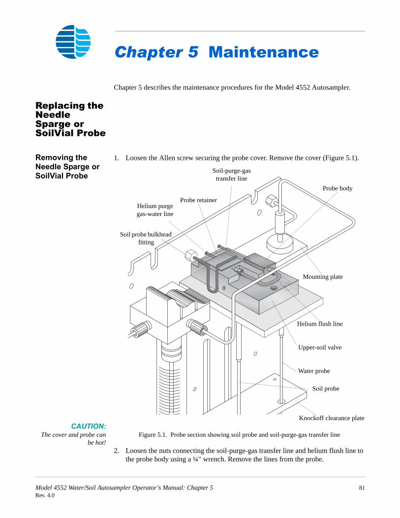
Chapter 5 Maintenance
Chapter 5 describes the maintenance procedures for the Model 4552 Autosampler.
Replacing the Needle Sparge or SoilVial Probe
Removing the Needle Sparge or SoilVial Probe
1. Loosen the Allen screw securing the probe cover. Remove the cover (Figure 5.1).
CAUTION:The cover and probe can
be hot!Figure 5.1. Probe section showing soil probe and soil-purge-gas transfer line
2. Loosen the nuts connecting the soil-purge-gas transfer line and helium flush line to the probe body using a ¼" wrench. Remove the lines from the probe.
Soil probe bulkhead fitting
Helium purge gas-water line
Probe retainer
Soil-purge-gas transfer line
Probe body
Mounting plate
Helium flush line
Upper-soil valve
Water probe
Soil probe
Knockoff clearance plate
Model 4552 Water/Soil Autosampler Operator’s Manual: Chapter 5 81Rev. 4.0

Maintenance
3. Loosen and remove the brass nut on the helium purge gas-water line with a T/qy" wrench.
4. Loosen the two #4-40 socket head screws securing the probe retainer. Slide the probe retainer back and expose the probe body (Figure 5.1).
5. Pull the probe out of the knockoff plate.
Installing the Needle Sparge or SoilVial Probe
1. Slide the probe tip (if it is a needle sparge version) through the hole in the mount and knockoff clearance plates.
2. Push the probe body into the heated housing. Be sure the top line slides into the notch in the block. Slide the probe retainer forward and tighten the two #4-40 screws.
3. Attach the soil-purge-gas transfer line and helium flush line.
4. Attach the T/qy" nut for the helium purge gas-water line to the bulkhead.
5. Verify all fittings are tight.
6. Replace the probe cover.
Model 4552 Water/Soil Autosampler Operator’s Manual: Chapter 5 82Rev. 4.0

Maintenance
Replacing the Water Probe
Removing the Water Probe
1. Loosen and remove the brass nut securing the pressurizing gas line to the bulkhead fitting using a T/qy" wrench (Figure 5.2).
Figure 5.2. Probe section showing water probe and water transfer line
2. Remove the plastic nut with the reverse ferrule securing the water transfer line to the valve manifold (Figure 5.2).
3. Loosen the retaining nut securing the water probe to the mounting plate.
4. Lift the water probe up and out.
Installing the Water Probe
1. Slide the water probe tip through the hole in the mounting plate and the hole in the knockoff plate.
2. Fingertighten the retaining nut.
3. Attach and tighten the T/qy" brass nut securing the pressurizing gas line to the bulkhead fitting.
4. Attach the plastic nut with reverse ferrule to the center hole in the valve manifold. Ensure the line with ferrule seats all the way to the bottom of the hole. Fingertighten the nut.
Mounting plate
Upper-soil valve
Water probe
Retaining nutSoil probe bulkhead fitting
Pressurizing gas line
Water transfer lineValve manifold
Model 4552 Water/Soil Autosampler Operator’s Manual: Chapter 5 83Rev. 4.0

Maintenance
Cleaning the Soil-purge-gas Transfer Line Frit
1. Remove the soil probe. See “Replacing the Needle Sparge or SoilVial Probe” on page 81 in this chapter.
2. Blow into the right side with 40–50 psi of clean air or nitrogen.
3. Install the soil probe. See “Replacing the Needle Sparge or SoilVial Probe” on page 81 in this chapter.
4. Verify all fittings are tight.
Replacing the Soil-purge-gas Transfer Line
Removing the Soil-purge-gas Transfer Line
1. Remove the probe cover. Loosen and remove the nut securing the soil-purge-gas transfer line to the upper-soil valve. (Figure 5.1)
2. Cut the end of the soil-purge-gas transfer line.
3. If necessary, remove any covers from the sample concentrator, allowing access to the fitting on the transfer line end. Disconnect the line from the sample concentrator.
4. Slide the soil-purge-gas transfer line out of the heater’s sheath.
Installing the Soil-purge-gas Transfer Line
1. Uncoil and straighten the new soil-purge-gas transfer line.
2. Insert the transfer line into the insulation sheath (Figure 3.13). Carefully slide the line all the way through until it is inside the cabinet. Blow helium into the line.
3. Slide the Valco nut and compression ferrule set onto the new line. Insert the soil-purge-gas transfer line with the nut and ferrule into the upper-soil valve. Tighten the nut using a ¼" open wrench.
4. Attach the other end to the sample concentrator, using the required fittings.
5. Recheck the fittings. Reinstall all covers.
Model 4552 Water/Soil Autosampler Operator’s Manual: Chapter 5 84Rev. 4.0

Maintenance
Replacing the Heated Upper-Soil Valve
1. Turn off power to the Model 4552 and unplug the power cord.
2. Remove the back panel by loosening the two quarter fasteners located at the panel top.
3. Remove the probe cover.
4. Loosen and remove the two Q/qy" lines installed in the upper-soil valve using a ¼" wrench. Loosen the two Allen screws holding the upper-soil valve in its mounting bracket (Figure 5.1).
5. Remove the cover plate under the mount plate by loosening the three Allen screws. Trace the wires to the back panel and unplug the connector. Remove the valve from its mount.
6. Install the new valve following the previous step in reverse order. Check the fittings and connector. Verify the Allen screws are snug. Reinstall the probe cover.
7. Plug in the Model 4552 and turn on the power.
Replacing the Water Line Screen
1. Remove the tan plastic nut and reverse ferrule from the valve manifold’s front fitting (Figure 5.2).
2. Use a small diameter pick or pointed wire to reach into the hole and pull out the screen.
3. Insert the new screen into the hole with the white side facing out.
4. Insert the tan plastic nut and reverse ferrule into the hole in the manifold. Fingertighten the nut.
Replacing the Soil-purge-gas Needle
1. Remove the sample tray.
2. Park the robotic arm in the front (see Chapter 4, “System Setup” on page 57).
3. Loosen the brass nut and remove the soil-purge-gas needle (located under the soil chamber) using a T/qy" nut driver or deep socket.
4. Replace the needle and tighten with the T/qy" wrench. Do not overtighten.
Model 4552 Water/Soil Autosampler Operator’s Manual: Chapter 5 85Rev. 4.0

Maintenance
Installing the Internal Standard Vials
Before beginning a sample run, verify the 5-mL standard vial(s) are filled with the required internal standard or surrogate. Fill the vials using the following procedure.
1. Turn the helium gas off using the toggle switch located on the instrument’s right-hand side near the probe assembly (Figure 5.3).
Figure 5.3. Internal standard vials and toggle switch
2. Grasp the vial and loosen the black thumb nut ½ turn. Slide the vial down, clearing the pickup tube.
3. Clean and dry the vial thoroughly. Fill the vial with approximately 5 mL of standard or surrogate.
4. Slide the vial up into the black thumb nut. Fingertighten the thumb nut until snug. Do not overtighten.
5. Turn on the toggle switch. Prime the lines (see Chapter 4, “System Maintenance” on page 59).
Cleaning the Vial Gripper
Clean the vial gripper arms approximately once a month, ensuring the gripper’s arms hold the vial properly (Figure 5.4).
1. Park the robotic arm in the front (see Chapter 4, “System Setup” on page 57).
2. Wipe the plastic-coated gripper using propanol and a soft laboratory tissue or cotton swab.
3. Move the robotic arm back.
Pickup tubes
Water sample supply lines
Waste lines
Thumb nut
Thumb nut
5-mL Vial
5-mL Vial
Vial gripper
Vial gripper arms
Figure 5.4. Vial gripper
Model 4552 Water/Soil Autosampler Operator’s Manual: Chapter 5 86Rev. 4.0

Maintenance
Checking the Helium Purge Gas Flow for Leaks
If the flow rates from the host purge-and-trap vent and the helium purge bulkhead fitting do not match, a leak exists. Locate the helium leak using the following procedures.
1. Check each fitting in the flow path using propanol and water. If all the fittings are leak tight, continue checking for leaks.
2. Remove the probe cover. Disconnect the short line going into the heated upper-soil valve from the probe body (Figure 5.2). Attach the tubing from a flowmeter to the line. Load a clean vial with a new septum in the tray and run it as a manual soil sample. Check the flow rate out of the line. It should be the same as the flow from the soil probe bulkhead fitting.
3. If the two flow rates are not equal, replace the vial and septum, and repeat the soil purge. If the flows still do not match, the soil probe is damaged. Replace the soil probe (see “Replacing the Needle Sparge or SoilVial Probe” on page 81 in this chapter).
4. If the flows match, check the flow coming out of the upper-soil valve. Remove the soil-purge-gas transfer line from the upper-soil valve.
5. Make a jig to test the flow using a short, 2–3 inch piece of Q/qy" O.D. stainless steel tubing, a Valco nut, and a two-piece compression ferrule. Insert the jig into the upper-soil valve and tighten. Measure the purge flow out of the jig. The flow should be equal to the flow from the bulkhead fitting (see Chapter 3, “Adjusting Soil Helium Purge Gas Flow” on page 38).
6. If the flows do not match, the upper-soil valve leaks. Replace the valve (see “Replacing the Heated Upper-Soil Valve” on page 85 in this chapter.)
7. If the flows do match, the fitting on the end of the soil-purge-gas transfer line in the sample concentrator leaks, or a leak exists within the sample concentrator.
8. Reattach the transfer line into the upper-soil valve and check the flow at the purge-and-trap vent. If the flows do not match, check the sample concentrator’s fitting on the soil-purge-gas transfer line, and check the sample concentrator for leaks per the manufacturer’s recommendations.
9. Use propanol and water to check all the fittings to ensure they are free of leaks.
Model 4552 Water/Soil Autosampler Operator’s Manual: Chapter 5 87Rev. 4.0

Maintenance
Adjusting the Sample Stir Motor Speed
Increase or decrease the sample stir motor speed by the adjusting a pot using a small screwdriver (Q/qy" flat blade or Phillips).
1. Locate the pot’s access hole on the Model 4552 back panel. The hole is below the 9-pin D-connector labeled “Remote RS-232.”
CAUTION:Do not change motor
speeds or accelerationrates unless necessary. The
default settings optimizeperformance. Consult OI
Analytical TechnicalSupport if motor rates
need changing.
2. Verify the stir motor is turned ON in the method. Start a manual sample.
3. Insert the screwdriver into the hole and rotate the pot. Rotating the pot clockwise increases the speed and rotating counterclockwise decreases the speed. Observe the response on the stir motor magnet.
NOTE: Do not push hard with the screwdriver. Only slight pressure is necessary.
4. Once the speed is adjusted, stop the run.
Cleaning the Drip Pan
Clean the drip pan located under the sample tray occasionally to prevent or remove any algae buildup.
1. Turn off the power to the Model 4552 and unplug the power cord.
2. Remove the sample tray (Figure 3.2).
3. Wipe the pan and clean the drain hole with a laboratory tissue or small brush.
4. Install the sample tray.
5. Plug in the power cord and turn on power to the Model 4552.
Model 4552 Water/Soil Autosampler Operator’s Manual: Chapter 5 88Rev. 4.0

Maintenance
Cleaning or Replacing the Syringe Plunger O-ring
Clean the 26-mL syringe plunger assembly once a month using the following procedure.
1. Remove the plunger assembly from the glass syringe (Figure 5.5).
Figure 5.5. Syringe assembly
2. Turn off the helium flow toggle switch.
3. Press [System]. Select Maintenance and press [Enter].
4. Select Clean Syringe and press [Enter]. The gripper moves to the front and the following message displays (Figure 5.6).
Figure 5.6. Remove Thumbscrew message
5. Remove the thumbscrew from the bottom of the plunger arm.
6. Press any key. As the plunger arm moves down, the display show “Clean Syringe.” When the movement stops, the following message displays (Figure 5.7).
Figure 5.7. Remove Phillips Screws message
Valve manifold assembly
Plunger
Syringe barrel
Thumbscrew
Plunger arm
Remove thumbscrewPress any key to continue
Remove the 2 Phillips screws from the block. Press any key to continue.
Model 4552 Water/Soil Autosampler Operator’s Manual: Chapter 5 89Rev. 4.0

Maintenance
7. After pressing a key, the following message displays (Figure 5.8).
Figure 5.8. Remove Syringe message
8. Gently pull the syringe barrel down off the valve manifold assembly. Examine the plunger and O-ring for any corrosion or damage. If the O-ring leaks or it is damaged, replace it.
9. If the O-ring requires cleaning, rinse the plunger assembly with a diluted (50:50) solution of acetic or nitric acid, and then rinse the plunger with very warm reagent water. Dry it with air or nitrogen. This removes any Teflon particles from the O-ring and salt deposits on the plunger body. Rinse the inside of the glass barrel with reagent water and wipe it dry with a soft laboratory tissue, ensuring the barrel and plunger are free of any residue.
CAUTION:Do not scratch the O-ring
and never use tools tomount it.
10. If the O-ring needs replacing, remove it from the plunger. Warm the new O-ring in warm reagent water for several minutes. Slide the new O-ring on the plunger from the back. Gently push the O-ring into the plunger’s groove. Ensure the barrel and plunger are free of any buildup.
11. Wet the top end of the 26-mL syringe glass barrel and the plunger assembly with warm water. Gently push the plunger back into the barrel.
12. Press any key and the following message displays (Figure 5.9).
Figure 5.9. Install syringe messageWARNING:
Carefully align the plungeralong the axis of the glass
barrel and do not force theplunger or it can break.
13. Replace the barrel and plunger assembly onto the valve manifold assembly. Push it up gently. Reinstall the support block with the two Allen socket head screws.
14. Press any key. The display show “Clean Syringe” and the plunger rod arm begins to move up. The following message displays (Figure 5.10).
Figure 5.10. Align plunger rod message
15. The plunger rod arm stops about ½" from the bottom of the plunger rod. Pull the plunger rod down into the hole in the arm.
Remove syringe Pull down carefullyPress any key to continue.
Install syringe Push up carefullyPress any key to continue.
Align plunger rodin plunger arm.Press any key to continue.
Model 4552 Water/Soil Autosampler Operator’s Manual: Chapter 5 90Rev. 4.0

Maintenance
16. Press any key. The display shows the following message (Figure 5.11).
Figure 5.11. Replace thumbscrew message
17. The display now shows “Clean Syringe” and the plunger moves up. The vial gripper moves back to the home position. Press [System] twice to return to the main menu.
18. Turn on the helium toggle switch.
Cleaning the Internal Standard Valve and Lines
If internal standard(s) recovery appears to be too low or is erratic, clean the lines to and from the internal standard valve and the valve rotor. Refer to Figure 5.3.
1. Turn off the helium toggle switch.
2. Remove the reservoir vial and disconnect the pickup tube. From the Valco valve, blow clean helium or nitrogen through the pickup valve tubes.
3. Disconnect the two waste lines from the Valco valve.
4. Blow clean nitrogen or helium through the lines.
5. Remove the water-sample supply lines connected to the valve bottom. Unscrew the opposite end of the lines from the manifold assemblies and blow clean nitrogen or helium through the lines.
6. Unscrew the knurled retaining knob on the front of the valve body. Do not use an Allen wrench.
7. Use a small pick to remove the valve rotor. If unsuccessful, try using a small magnet.
NOTE: The groove (loop) position on the rotor must be down.
8. Blow clean nitrogen or helium through the valve from the front. Ensure flow comes out of each hole.
9. Reattach all lines to their proper locations. Verify all fittings are tight.
10. Insert the rotor into the valve. Install the knurled knob, and fingertighten the knob until it no longer rotates.
11. Turn on the helium toggle switch.
Replace thumbscrewPress any key to continue
Model 4552 Water/Soil Autosampler Operator’s Manual: Chapter 5 91Rev. 4.0

Maintenance
NOTE: If removing the 5-mL standard reservoir vials are necessary, be very certain the helium toggle switch is off. Grasp the vial before rotating the black thumb nut.
Model 4552 Water/Soil Autosampler Operator’s Manual: Chapter 5 92Rev. 4.0

Chapter 6 Troubleshooting
The following chart outlines the most common problems that can occur when using the Model 4552, along with their corresponding corrective actions. More than one problem can cause each symptom. If a problem still exists after reviewing the following chart or if a particular problem is not addressed, contact OI Analytical Technical Support at (800) 336-1911 or (979) 690-1711 for assistance.
Screen Message Probable Cause
Must Calibrate (Target Position) first.Vial 1 PositionWater ProbeEquilibrium BlockKnock off ClearancePress any key to reset.
One of the above calibrations did not perform. See Chapter 4, “Calibrating the System” on page 61.
First vial > last in method #.Press any key to continue.
The first vial number in the method shown is larger than the last vial number. Edit the method and change the vial number entries.
Vial # type is different in method # and method #. Press any key to continue.
Duplicate sample type settings exist for the indicated vial for two or more methods.
Position out of range. Try again. Press any key to continue.
Current settings are greater than ¼" from previous settings.
Could not sense vial. Press any key to continue.
The vial sensor switch does not detect a vial. The sensor may be damaged or the vertical coordinate setting may be incorrect. See Chapter 4, “Operation” on page 39.
Can’t Front Park while running. Press any key to continue.
The Model 4552 attempted the front park command while running.
Can’t calibrate while running. Press any key to continue.
The Model 4552 attempted the calibration setup while running.
Can’t diagnose while running. Press any key to continue.
The Model 4552 attempted one of the system diagnostics while running.
(Elevator or Syringe) already homed error. Pos (#). Press any key to reset.
The elevator or syringe motor arrived home too early, indicating a slipped belt, motor, or electronic problem.
Model 4552 Water/Soil Autosampler Operator’s Manual: Chapter 6 93Rev. 4.0

Troubleshooting
(Elevator or Syringe) not homed error. Pos (#). Press any key to reset.
The elevator or syringe motor does not reach home, indicating a slipped belt, a failed motor, or an electronic problem.
(Elevator or Syringe) homed error. Pos (#). Press any key to reset.
The elevator or syringe motor never reached home. The motor is out of position, indicating a slipped belt, failed motor switch, or electronic problem.
(Left/Right) get position timeout.Front/RearVerticalPress any key to reset.
A communication failure between the motor board and processor board occurred. Check for a poor connection or defective cable.
Serial Error.Press any key to reset.
Bad or no internal communication between internal boards or cables occurred. Check the cables and reboot.
At home timeout. Motor failure. Press any key to reset.
An internal communication failure occurred. Check the cables and reboot.
Could not step off vial.Press any key to reset.
The vial sensor switch continuously detects a vial, indicating no helium, a broken switch, or a mechanical problem with the gripper.
Stuck vial.Press any key to reset.
The vial jammed or became stuck in the gripper. A vial sensor switch may be damaged.
Could not sense vial (#) in vial type slot. Press any key to reset.
The vial sensor does not detect the vial located in the vial ID cup. This may indicate a damaged vial sensor switch, incorrect coordinate, or mechanical problem.
Soil vial can’t be run as Needle Sparge. Press any key to continue.
A system identified a SoilVial in the ID cup when System Option Needle Sparge is YES.
Water/Soil vial can’t be run in a Water/Soil method.
The vial type does not match the method type.
Remove vial (#) from the tray. Press any key to continue.
The gripper tried to load a vial in a position that already contained a vial. Remove the vial from the position and continue.
Screen Message Probable Cause
Model 4552 Water/Soil Autosampler Operator’s Manual: Chapter 6 94Rev. 4.0

Troubleshooting
Didn’t sense vial. Put it in the tray and press any key.
The gripper tried to move a vial back to the tray, and no vial was detected. Check the equilibrium block and tray for any vials that may be loaded incorrectly.
Check for jammed vial or low helium pressure. Press any key to reset.
A vial jammed the arm, indicating low helium pressure or a home sensor failure.
Error resetting motor board. Press any key to reset.
An internal board communication failure occurred.
Standard home error. Press any key to reset.
The standard motor failed to reach home, indicating a motor failure, mechanical jam, or sensor failure.
Stack overflow.Press any key to reset.
Contact OI Analytical Technical Support.
Subroutine? not found.Press any key to reset.
Contact OI Analytical Technical Support.
Invalid jump label.Press any key to reset.
Contact OI Analytical Technical Support.
Invalid command.Press any key to reset.
Contact OI Analytical Technical Support.
Incomplete setup/startup. A communication failure between the motor control board and the processor board occurred. Check for a poor connection, defective cable, or bad processor board.
Lost vial. Press any key to reset. The gripper lost a vial. Check for a jammed vial or damaged sensor.
Replace vial (#) in the tray. Press any key to continue.
A vial was removed from the tray or equilibrium block. Check the vial locations and replace the vial.
Screen Message Probable Cause
Model 4552 Water/Soil Autosampler Operator’s Manual: Chapter 6 95Rev. 4.0

Troubleshooting
Model 4552 Water/Soil Autosampler Operator’s Manual: Chapter 6 96Rev. 4.0

Chapter 7 Replacement Parts
This chapter provides a list of replacement parts and support items for the Model 4552. An asterisk indicates replacement parts that are considered expendable (XPN). Replace expendable parts regularly, since they may become deformed or broken. Keep a supply of expendable parts in stock
.
Table 7.1. Electronics
Product Unit PN XPN
Keypad each 03-505254-00
LCD display each 03-505236-00
Motor control each 03-504914-00
Power supply each 03-504763-00
Processor each 03-505249-00
Remote I/O each 03-505240-00
Table 7.2. Gas controllers
Product Unit PN XPN
Helium flow controller each 03-504156-00
Purge gas pressure gauge each 27-239992-00
Purge gas regulator each 03-502772-00
Rear regulator each 03-918707-05
Table 7.3. Interface cables
Product Unit PN XPN
Handshake pigtail cable to Agilent® 6890 each 252213
Handshake pigtail cable to Agilent 5890 each 185868
Handshake pigtail cable to Varian® 3400 each 188409
Model 4552 Water/Soil Autosampler Operator’s Manual: Chapter 7 97Rev. 4.0

Replacement Parts
Handshake pigtail cable to Shimadzu® 17A each 244483
Interface cable to Model 4460/4560 each 284935
Interface cable to Model to Varian 3400/3600 each 251694
Interface cable to Model to Agilent 5890, RTE Agilent 1000 GC/MS software, Agilent 5970 MSD or Agilent 5988 MS
each 03-505875-00
Interface cable to Tekmar LSC-2000/3000 to spade lugs
each 03-505872-00
Interface cable to Tekmar LSC-2000/3000 to Agilent 5890
each 03-505869-00
Interface cable to Tekmar LSC-2000/3000 to Varian 3400/3600
each 03-505868-00
Interface cable to Tekmar 2000/3000 with Agilent 6890
each 03-505873-00
Interface cable to Tekmar 2000/3000 w/ Agilent 5890 with 5970/71/72 MSD and Unix-B or MS-DOS, and Agilent 5890/5989MS Engine
each 03-505874-00
Interface cable to Tekmar LSC-2000/3000 w/ Agilent 5895/96/85/87/88/92 GC/MS
each 03-505876-00
Interface cable to Tekmar 3000 w/ Varian 3800 each 03-925673-01
Table 7.4. Interface kits
Product Unit PN XPN
Model 4560 to Model 4552 interface kit each 276592
Model 4460 or Tekmar LSC-2 to Model 4552 interface kit
each 276584
Sparge mount heater kit each 311738
Tekmar 2000/3000 to Model 4552 interface kit each 293043
Table 7.3. Interface cables
Product Unit PN XPN
Model 4552 Water/Soil Autosampler Operator’s Manual: Chapter 7 98Rev. 4.0

Replacement Parts
Table 7.5. Internal standard parts
Product Size Unit PN XPN
Ferrule, Teflon for reservoir vial E/i" each 03-694637-00 *
Internal standard valve, Valco, six-way
each 03-505478-00
Internal standard valve, Valco, six-way w/ motor
each 03-505879-00
Rotor loop 1 µL each 03-505726-00
Standard reservoir mount each 03-505604-00
Standard reservoir vial 5 mL each 03-505484-00 *
Table 7.6. Lines and fittings
Product Size Unit PN XPN
Ferrule, Valco Q/qy" 5/pk 196246 *
Ferrule set, stainless steel, Swagelok Q/qy" 5/pk 178277 *
Ferrule set, flangeless w/ fitting Q/qy" 8/pk 03-700081-01 *
Nut, stainless steel Q/qy" 5/pk 169715 *
Nut, Valco Q/qy" 5/pk 196311 *
Soil-purge-gas transfer line (nickel tubing only)
each 03-505745-00 *
Soil-purge-gas transfer line w/ heater assembly
each 03-700001-01
Soil-purge-gas transfer line w/ heater assembly and bracket/clamp, Model 4560 or Tekmar 2000/3000 (SN ≤12047)
each 03-700025-90
Standard internal pickup line each 03-700020-00 *
Transfer line, stainless steel 0.062" x 0.040" x
60"
each 03-505514-00 *
Waste line replacement kit each 03-700019-90
Model 4552 Water/Soil Autosampler Operator’s Manual: Chapter 7 99Rev. 4.0

Replacement Parts
Table 7.7. Miscellaneous parts
Product Unit PN XPN
Heater cartridge for Model 4560 each 233700
Magnet each 03-505461-00
Reservoir bottle plug assembly each 03-505816-00
Reservoir bottle top each 03-503055-00
Reservoir bottle, safety coated, 80 oz each 03-503906-00
Sparge mount heater kit each 311738
Thermocouple for Model 4560 each 227314
Water cup each 03-505451-00
Water probe screen, 10 µm each 03-505598-00 *
Water/elevator plate each 03-505433-00
Table 7.8. Options
Product Unit PN XPN
Bar code reader (requires Windows software) each 276709
Calibration bar and pin each 03-505419-00
Needle sparge conversion to SoilVials kit each 276717
Recirculating bath for cooling sample vials each 261909
Recirculating bath tubing kit each 302810
Rinse water kit (replaces reservoir bottle) each 276725
Sample tray each 03-505223-00
Sample tray cooling each 03-700085-90
SoilVials conversion to needle sparge kit each 276733
Windows software each 03-505629-00
Model 4552 Water/Soil Autosampler Operator’s Manual: Chapter 7 100Rev. 4.0
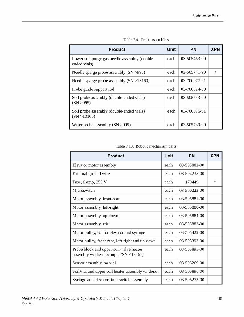
Replacement Parts
Table 7.9. Probe assemblies
Product Unit PN XPN
Lower soil purge gas needle assembly (double-ended vials)
each 03-505463-00
Needle sparge probe assembly (SN >995) each 03-505741-90 *
Needle sparge probe assembly (SN >13160) each 03-700077-91
Probe guide support rod each 03-700024-00
Soil probe assembly (double-ended vials) (SN >995)
each 03-505743-00
Soil probe assembly (double-ended vials) (SN >13160)
each 03-700076-91
Water probe assembly (SN >995) each 03-505739-00
Table 7.10. Robotic mechanism parts
Product Unit PN XPN
Elevator motor assembly each 03-505882-00
External ground wire each 03-504235-00
Fuse, 6 amp, 250 V each 170449 *
Microswitch each 03-500223-00
Motor assembly, front-rear each 03-505881-00
Motor assembly, left-right each 03-505880-00
Motor assembly, up-down each 03-505884-00
Motor assembly, stir each 03-505883-00
Motor pulley, ¼" for elevator and syringe each 03-505429-00
Motor pulley, front-rear, left-right and up-down each 03-505393-00
Probe block and upper-soil-valve heater assembly w/ thermocouple (SN <13161)
each 03-505895-00
Sensor assembly, no vial each 03-505269-00
SoilVial and upper soil heater assembly w/ donut each 03-505896-00
Syringe and elevator limit switch assembly each 03-505273-00
Model 4552 Water/Soil Autosampler Operator’s Manual: Chapter 7 101Rev. 4.0

Replacement Parts
Syringe motor assembly each 03-505878-00
Timing belt, front-rear motor each 03-505362-00 *
Timing belt, left-right motor each 03-505372-00 *
Timing belt, up-down motor each 03-505384-00 *
Timing belt, vial elevator and syringe motors each 03-505477-00 *
Timing pulley, leadscrew each 03-505363-00 *
Upper-soil-valve heater assembly (SN >13160) each 03-700072-01
Vial gripper block assembly each 03-505844-00
Vial gripper O-ring each 03-101662-00 *
Vial gripper piston each 03-505389-00 *
Water heater assembly each 03-505596-00
Table 7.11. Syringe parts
Product Unit PN XPN
Plunger assembly, 26 mL each 03-700060-91
Plunger drive bracket each 03-505439-00
Plunger rod each 03-502959-00
Syringe glass barrel each 03-502968-00
Syringe mixing manifold assembly each 03-505830-00
Syringe mount each 03-505450-00
Syringe O-ring each 03-505495-00 *
Syringe packing each 03-505441-00
Syringe thumbscrew each 03-500007-00
Syringe, Luer-Lok, 10 mL each 182006
Syringe, Luer-Lok, 5 mL each 177659
Water probe screen, 10 µm each 03-505598-00
Table 7.10. Robotic mechanism parts
Product Unit PN XPN
Model 4552 Water/Soil Autosampler Operator’s Manual: Chapter 7 102Rev. 4.0

Replacement Parts
Table 7.12. Valves
Product Unit PN XPN
Helium manifold replacement assembly each 03-700108-90
Purge gas cutoff valve assembly (SN >995 and <12047)
each 03-505791-00
Purge gas cutoff valve assembly (SN >12047) each 03-505899-03
Solenoid mixing manifold assembly each 03-505831-00
Upper-soil-valve upgrade kit (SN <120039) each 03-700039-90
Valve assembly, two-way soil purge gas solenoid (standard mount)
each 03-505899-01
Valve assembly, two-way soil transfer gas solenoid (manifold mount) (SN >12953)
each 03-700111-00
Valve assembly, three-way gripper solenoid (standard mount)
each 03-505899-02
Valve assembly, three-way pressure gas solenoid (manifold mount) (SN >12953)
each 03-700112-00
Valve assembly, Burkert solenoid each 03-505720-00
Valve, heated three-way, upper soil (SN >120039) each 03-700032-00
Table 7.13. Vials and septa
Product Unit PN XPN
USEPA water vials, 40 mL 6/pk 03-505081-00 *
Low-bleed soil septa 60/pk 03-504252-00 *
Low-bleed soil septa 300/pk 03-504104-00 *
Screw cap vials, 40 mL (w/ caps and septa) 72/pk 296053 *
SoilVial, 40 mL (double-ended) 6/pk 03-504099-00 *
Stir bar, Teflon for VOA vials each 03-502955-00 *
Stir bar for SoilVials each 03-504024-00 *
Water vial septa, Teflon/silicon 72/pk 296061 *
Model 4552 Water/Soil Autosampler Operator’s Manual: Chapter 7 103Rev. 4.0

Replacement Parts
Model 4552 Water/Soil Autosampler Operator’s Manual: Chapter 7 104Rev. 4.0

Chapter 8 Cable Connections
Use the following diagrams to interface the Model 4552, sample concentrator, and GC, allowing correct signals to be sent and received. Each sample concentrator and GC make and model differ slightly in their I/O connections. Contact OI Analytical Technical Support for additional information.
Connecting to the Eclipse or Model 4560 with an Agilent 6890N GC
Connect the Model 4552 to an OI Analytical Eclipse or Model 4560 Sample Concentrator with an Agilent 6890N GC using the following instructions (Figure 8.1).
NOTE: If needing two remote signal connections, e.g., the Eclipse or Model 4560 and a mass spectrometer, connect as shown in Figure 8.1. If the Eclipse or Model 4560 is the only unit connecting to the remote connection, see Figure 8.3.
Figure 8.1. Connecting a Model 4552 to an Agilent 6890N
1. Connect cable 1’s DB9 male connector to the remote signals connector on the Agilent 6890N GC (the other male end is not connected). Connect the other nine-
�������� ��������
��������������
����
������������ !�
��������������
��
MSD/other connection
(DB9 female) Remote
Cable 1 Cable 2
DB9 male (not connected)
Cable 3Cable 4
Relay I/O A
Relay I/O B
Cable 1: Agilent H cable (PN 300954) Cable 2: Agilent 6890 handshake cable (PN 252213)Cable 3: Eclipse or 4560 interface cable (PN 226530)Cable 4: 4552-to-Eclipse or 4560 interface cable (PN 284935)
MSD/other connection
(DB9 female) Remote
Cable 1 Cable 2
DB9 male (not connected)
Cable 3Cable 4
Relay I/O B
Relay I/O A
Model 4552 Water/Soil Autosampler Operator’s Manual: Chapter 8 105Rev. 4.0

Cable Connections
pin female connector to the Agilent mass spectrometer or other devices requiring a remote I/O.
WARNING:Turn off and unplug allinstruments if removing
any panels to installcables.
2. Connect the appropriate end of cable 2 to cable 1. Connect cable 2’s other end to the appropriate end of cable 3.
3. Connect cable 3’s other end to the Eclipse’s or Model 4560’s relay I/O B connector.
4. Connect cable 4’s green connector to the Eclipse’s or Model 4560’s relay I/O A connector, and plug the other end into the remote I/O connector on the Model 4552 back.
5. Set the Model 4560 for the Agilent 6890N signal by pressing [2ND] [F6] on the Model 4560 keypad. Set the signal to Inverted.
Set the Eclipse for the Agilent 6890N signal through the Advanced Configure screen (Figure 8.2).
Figure 8.2. Advanced Configure screen
• Press the Config icon to access the General configuration screen.
• Select the 4552 configuration by pressing and highlighting its named icon and pressing View/Modify, or create a new configuration by pressing Add.
• Press the Advanced tab to access the Advanced Configure screen.
• Set the Expect Ready from GC to Inverted.
Model 4552 Water/Soil Autosampler Operator’s Manual: Chapter 8 106Rev. 4.0

Cable Connections
NOTE: Eclipse or Model 4560 relay I/O A hardwired connections:
5 Green – COM4 Brown – N.O.7 Red – IN8 White (or yellow) – GND1 Blue – COM2 Black – N.O.
NOTE: If the GC does not start at desorb or the data system constantly starts, switch the position of connections 4 and 5.
Connecting to the Eclipse or Model 4560 with an Agilent 5890 or 6890 GC
Connect the Model 4552 to an OI Analytical Eclipse or Model 4560 Sample Concentrator with an Agilent 5890/6890 GC using the following instructions (Figure 8.3).
Figure 8.3. Connecting a Model 4552 to an Agilent 5890 or 6890 GC
1. Connect cable 1 to the remote signals connector on the Agilent 5890 or 6890 GC.
2. Connect the appropriate end of cable 2 to cable 1. Connect the cable 2’s other end to the Eclipse’s or Model 4560’s relay I/O B connector.
3. Connect the cable 3’s green connector to the Eclipse’s or Model 4560’s relay I/O A connector, and plug the other end into the remote I/O connector on the Model 4552 back.
�������� ��������
�����������"������
����
������������ !�
�����������"������
��
Remote
Cable 1 Cable 2
Cable 3
Relay I/O A
Relay I/O B
Cable 1A: Agilent 6890 handshake cable (PN 252213) Cable 1B: Agilent 5890 handshake cable (PN 185868)Cable 2: Eclipse or 4560 interface cable (PN 226530)Cable 3: 4552-to-Eclipse or 4560 interface cable (PN 284935)
Remote
Cable 1Cable 2
Cable 3Relay I/O A
Relay I/O B
Model 4552 Water/Soil Autosampler Operator’s Manual: Chapter 8 107Rev. 4.0

Cable Connections
4. Set the Model 4560 for the Agilent 6890 signal by pressing [2ND] [F6] on the Model 4560 keypad. Set the signal to Inverted. Change the signal to “inverted”. For the Agilent 5890, set the signal to Normal.
Set the Eclipse for the Agilent 6890N signal through the Advanced Configure screen (Figure 8.2).
• Press the Config icon to access the General configuration screen.
• Select the 4552 configuration by pressing and highlighting its named icon and pressing View/Modify, or create a new configuration by pressing Add.
• Press the Advanced tab to access the Advanced Configure screen.
• Set the Expect Ready from GC to Inverted for the Agilent 6890. Set to Normal for the Agilent 5890.
Cable Pinouts The following figures show the cable pinouts for the Model 4552 to a Eclipse or Model 4560 Sample Concentrator with an Agilent 5890, 6890, or 6890N Series GC.
Figure 8.4. Handshake cable to Agilent 5890 (PN 185868)
Table 8.1. Pinouts for the handshake cable to Agilent 5890
Connector P2
Connector P3
Connector P1 Color Function
— 2 1 Black Ground
— 1 7 Red Eclipse or 4560 remote start out
— 4 9 Green GC ready COM
— 3 11 White GC ready N.O.
1234
65
789101112
P21 Blue2 Orange
P31 Red2 Black3 White4 Green
To 4560 interface cable
To GC
P1
1 7
2 8
3 9
4 10
5 11
6 12
Model 4552 Water/Soil Autosampler Operator’s Manual: Chapter 8 108Rev. 4.0

Cable Connections
Figure 8.5. Handshake cable to Agilent 6890 (PN 252213)
Figure 8.6. System interface cable to Eclipse or Model 4560 (PN 226530)
2 — 4 Orange GC start out
1 — 10 Blue Ground
— — N/A Brown Not used
Table 8.2. Pinouts for the handshake cable to Agilent 6890
Connector A Color Function Connector
B
1 Red Start 3
2 Black Ground 1
4 Green Ready 7
3 White Ground 1
Table 8.1. Pinouts for the handshake cable to Agilent 5890
Connector P2
Connector P3
Connector P1 Color Function
To 4560 interface cable
To GC
A B
P14 Red5 Black3 White2 Green
To Eclipse or Model 4560
To GC handshake cable
P41 Red2 Black3 White4 Green
P21 Red2 Black
P31 Red2 Black
Model 4552 Water/Soil Autosampler Operator’s Manual: Chapter 8 109Rev. 4.0

Cable Connections
NOTE: For external data systems, use P2 or P3 – pin 1, Red (remote start out) and pin 2, black (COM) to start.
Figure 8.7. Handshake cable to Eclipse or Model 4560 (PN 284935)
Table 8.3. Pinouts for the system interface cable to Eclipse or Model 4560
Connector P1 Color Function Connector
P4Connector
P2 Connector
P3
2 Green GC ready COM
4 — —
3 White GC ready N.O.
3 — —
4 Red Remote start out
1 1 1
5 Black Ground 2 2 2
Table 8.4. Pinouts for the handshake cable to Eclipse or Model 4560
Connector P1 Color Function Connector
P2
14 Blue Standby, signal input 1
1 Black Ground 2
2 Brown Ground 4
15 Green Drain, signal input 5
5 Red Start purge relay out (N.O.) 7
18 Yellow Start purge relay out (COM) 8
3 — Drain —
P2 P1
Pin 1 Pin 1To Eclipse or Model 4560
To Model 4552
Model 4552 Water/Soil Autosampler Operator’s Manual: Chapter 8 110Rev. 4.0

Cable Connections
Model 4552 Remote I/O Connector Signal Pinouts
All pinouts in italics are used on the Model 4552’s cables.
Table 8.5. Remote I/O connector signal pinouts
Pin Number Signal Wire
Color
1 Logic ground Black
2 Logic ground Brown
3 Logic ground
4 Logic ground
5 Start purge (N.O.), relay output Red
6 Start purge (N.C.)
7 Soil purging (COM)
8 Aux output (N.O.)
9 Aux output (N.C.)
10 Soil purging 2 (COM)
11 Serial output Reserved
12 Serial clock Reserved
13 Serial load Reserved
14 Standby (L), signal input Blue
15 Drain (L), signal input Green
16 Emergency stop (L)
17 Spare Reserved
18 Start purge (COM), relay output White
19 Soil purging (N.O.)
20 Soil purging (N.C.)
21 Aux output (COM)
22 Soil purging 2 (N.O.)
23 Soil purging 2 (N.C.)
24 Not used
25 +5 VDC Reserved
Model 4552 Water/Soil Autosampler Operator’s Manual: Chapter 8 111Rev. 4.0

Cable Connections
Connecting to the Tekmar 3000 with Any GC
Connect the Model 4552 to a Tekmar 3000 using the following instructions (Figure 8.8 and Table 8.6).
Figure 8.8. Handshake cable to Tekmar 3000 (PN 03-505872-00)
*#6 Spade terminal
1. Specify the Tekmar GC port:
• At the Standby screen, press [CONF].
• At the Configuration screen, press [A] (GC I/O Port). The GC Port screen appears.
• Choose Standard and GC Type = 63. Press [ENTER] to save the selection.
• Turn off the instrument.
2. Program the Tekmar 3000 to give a switch closure at purge ready. This switch closure tells the Model 4552 to begin the sample cycle.
Table 8.6. Pinouts for the handshake cable to Tekmar 3000 to Agilent 5890
4552 Function Pin No. Color
TekmarFunction Color
In Out
Desorb 15 Green 24 3 GC ready Green*
Drain 2 Brown 23 4 GC ready White*
Start 5 Red 1 21 GC start Red*
Purge 18 White 2 22 GC start Black*
P&T 14 Blue 16 21 Start Red
Ready 1 Black 15 22 Start Black
Male
Female
Red Black
Model 4552 Water/Soil Autosampler Operator’s Manual: Chapter 8 112Rev. 4.0

Cable Connections
3. Select method 14 to provide correct polarity settings for purge ready output. If selecting another method, refer to the Tekmar 3000 Operator’s Manual for additional information.
4. Connect the cable to the Model 4552 and sample concentrator. The spade terminals attach to the GC and data system at their appropriate connections. Refer to the GC and data system operator’s manuals for correct connector locations.
NOTE: Be sure the locking screws on the cable secure the connector to the instrument chassis.
Connecting to the Tekmar 3000 with an Agilent 5890 GC
Connect the Model 4552 to the Tekmar 3000 with an Agilent 5890 GC using the following instructions (Figure 8.9 and Table 8.7).
Figure 8.9. Handshake cable to Tekmar 3000 to Agilent 5890 (PN 03-505869-00)
Table 8.7. Pinouts for the handshake cable to Tekmar 3000 to Agilent 5890
4552 Function
Pin No. Color
TekmarFunction Color Agilent
5890In Out
Desorb 15 Green 24 3 GC ready Green 5
Drain 2 Brown 23 4 GC ready White 9
Start 5 Red 1 21 GC start Red 1
Purge 18 White 2 22 GC start Black 2
P&T 14 Blue 16 21 Start Red To Data
Ready 1 Black 15 22 Start Black System
Male
Female
Red Black
11 12
1 2
Model 4552 Water/Soil Autosampler Operator’s Manual: Chapter 8 113Rev. 4.0

Cable Connections
1. Specify the Tekmar GC port.
• At the Standby screen, press [CONF].
• At the Configuration screen, press [A] (GC I/O Port). The GC Port screen appears.
2. Choose Standard. Press [ENTER] to save the selection.
3. Turn off the instrument.
4. Program the Tekmar 3000 to give a switch closure at purge ready. This switch closure tells the Model 4552 to begin the sample cycle.
5. Select method 14 to provide correct polarity settings for the purge ready output. If another method is selected, refer to the Tekmar 3000 Operator’s Manual for additional information.
6. Connect the cable to the Model 4552 and sample concentrator. The 12-position connector attaches to the Agilent 5890 GC and the red and black connectors to the data system. Refer to the GC and data system operator’s manuals for correct connector locations.
NOTE: Be sure the locking screws on the cable secure the connector to the instrument chassis.
Model 4552 Water/Soil Autosampler Operator’s Manual: Chapter 8 114Rev. 4.0

Cable Connections
Connecting to the Tekmar 3000 with a Varian 3400/3600 GC
Connect the Model 4552 to the Tekmar 3000 with a Varian 3400/3600 GC using the following instructions (Figure 8.10 and Table 8.8).
Figure 8.10. Handshake cable to Tekmar 3000 to Varian 3400/3600 (PN 03-505868-00)
1. Specify the Tekmar GC port.
• At the Standby screen, press [CONF].
• At the Configuration screen, press [A] (GC I/O Port). The GC Port screen appears.
• Choose Standard. Press [ENTER] to save the selection.
• Turn off the instrument.
2. Program the Tekmar 3000 to give a switch closure at purge ready. This switch closure tells the Model 4552 to begin the sample cycle.
Table 8.8. Pinouts for the handshake cable to Tekmar 3000 to Varian 3400/3600
4552 Function
Pin No. Color
TekmarFunction Color
J23–J16
MotherboardIn Out
Desorb 15 Green 24 3 GC ready Green 3 (P23)
Drain 2 Brown 23 4 GC ready White 1 (P23)
Start 5 Red 1 21 GC start Red 4 (P16)
Purge 18 White 2 22 GC start Black 3 (P16)
P&T 14 Blue 16 21 Start Red To Data
Ready 1 Black 15 22 Start Black System
#
�
$
�
�
#
�
$
�
Male
Female
Red Black
P23
P16
Model 4552 Water/Soil Autosampler Operator’s Manual: Chapter 8 115Rev. 4.0

Cable Connections
3. Select method 14 to provide correct polarity settings for the purge ready output. If another method is selected, refer to the Tekmar 3000 Operator’s Manual for additional information.
4. Connect the cable to the Model 4552 and sample concentrator. Connectors P23 and P16 attach to the Varian 3400/3600 GC motherboard at connectors J23 and J16. Secure the grounding clamp to the GC chassis. Attach the red and black wires to the data system. Refer to the GC and data system operator’s manuals for correct connector locations.
NOTE: Be sure the locking screws on the cable secure the connector to the instrument chassis.
NOTE: Be sure to select Aquatek 50.
When installing the Model 4552 onto a Varian 3400 or 3600 GC with a Star Workstation, connectors from both the Model 4552 I/O cable and the Star Workstation cable must access the J16 and J23 connectors on the GC motherboard. Make this connection with the J16 splitter (PN 03-700030-00) and J23 splitter (PN 03-700031-00) using the following instructions (Figure 8.11 and Figure 8.12):
Figure 8.11. Varian GC motherboard attachments for J16 and J23
#
�
�
$
#�
�$
�
#�
#�
# #
$ $
��
��
%
$�
$�
J16 splitter(03-700030-00)
J23 Splitter(03-700031-00)
J16Ready in
Start in
Varian GC motherboard
J23Ready out
Start out
P16
P16
Attaching cables
Star Workstation cable
4552 remote I/O cable
Ready out
Start out at beginning of desorb
4552 remote I/O cable
Ready in
Star Workstation cableStart in
2 Key
Model 4552 Water/Soil Autosampler Operator’s Manual: Chapter 8 116Rev. 4.0

Cable Connections
Figure 8.12. J16 and J23 splitters
1. Turn off the power and unplug the power cord from the GC. Remove the top panels to access the GC motherboard.
2. Route the GC end of the Model 4552 I/O cable and the GC end of the Star Workstation cable through the GC’s back panel.
3. Connect the five-pin female Molex® connector (P-23) from the Star Workstation cable to the male connector on the J23 splitter with four pins (the #2 position lacks a pin).
4. Connect the five-pin female Molex connector from the Model 4552 I/O cable to the five-pin male connector on the J23 splitter.
5. Connect the J23 splitter to the J23 connector on the GC motherboard (see the GC operator’s manual for the motherboard layout schematic).
6. Connect the four-pin female Molex connector from the Model 4552 I/O cable to either of the four-pin male connectors on the J16 splitter.
7. Connect the four-pin female Molex connector (P16) from the Star Workstation cable to either of the four-pin male connectors on the J16 splitter.
8. Connect the J16 splitter to the J16 connector on the GC motherboard (see the GC operator’s manual for the motherboard layout schematic).
9. Complete the installation of the Model 4552 I/O cable and the Star Workstation cable according to the standard instructions for those cables.
The following sequence occurs when the Model 4552 and a sample concentrator are configured with the Varian 3400 and 3600 GC with the Star Workstation:
1. The Model 4552 begins sample handling after receiving a ready signal from the sample concentrator. As configured above, the sample concentrator goes to ready
�&'(���$�'��
��)#
�&'(���$#'��
��)#
J16 splitter
J23 splitter
Model 4552 Water/Soil Autosampler Operator’s Manual: Chapter 8 117Rev. 4.0

Cable Connections
without waiting for the GC. This allows the operator to prepare the GC and the Star Workstation while the sample purges and collects in the sample concentrator.
2. The sample concentrator collects the purged sample onto its trap and waits for a ready signal from the GC. This occurs after the workstation issues a ready signal to the GC through the workstation’s cable plug attached to the GC’s J16 ready in pins 1 and 2. In turn, the GC sends a ready out signal from its J23 pins 1 and 3, to the Model 4552 I/O cable.
3. When the sample concentrator completes its purge cycle and detects a ready signal from the GC, the sample concentrator desorbs the sample from its trap and issues a desorb out signal to both the Model 4552 and to the Varian GC. This signal travels through the remote I/O cable supplied with the Model 4552.
4. The desorb out signal from the sample concentrator starts the Model 4552’s autodrain cycle, which drains the sparge vessel if the water-sample method is running on the Model 4552.
5. The desorb out signal simultaneously travels through the Model 4552 remote I/O cable to its connector attached to the GC’s J16 start in pins 3 and 4, and initiates the GC run. The GC in turn initiates a start out signal through J23 pins 4 and 5, which triggers the workstation to begin data collection.
Model 4552 Water/Soil Autosampler Operator’s Manual: Chapter 8 118Rev. 4.0

Cable Connections
Connecting to the Tekmar 3000 with an Agilent 5895/96/85/87/88/92
Connect the Model 4552 to the Tekmar 3000 with an Agilent 5895/96/85/87/88/92 GC/MS with Agilent-1000/RTE GC/MS software and an Agilent 5890 MSD RTE (RTE-A, RTE-6, or Rev F2) using the following instructions (Figure 8.13 and Table 8.9).
Figure 8.13. Handshake cable to Tekmar 3000 to Agilent 5895/96/85/87/88/92 (PN 03-505876-00)
1. Specify the Tekmar GC port.
• At the Standby screen, press [CONF].
• At the Configuration screen, press [A] (GC I/O Port). The GC Port screen appears.
• Choose Standard. Press [ENTER] to save the selection. (Master mode) or user, GC Type = 32 (slave mode).
Male
Female
Table 8.9. Pinouts for the handshake cable to Tekmar 3000 to Agilent 5895/96/85/87/88/92
4552 Function
Pin No. Color
TekmarFunction Color Connection
In Out
Desorb 15 Green 24 3 GC ready Red 25/27
Drain 2 Brown 23 4(Slave)
GC ready Black 26/28
Start 5 Red 1
Purge 18 White 2
P&T 14 Blue 16 21 GC/MS remote
start button
Ready 1 Black 15 22(Master)
GC/MS remote
start button
Model 4552 Water/Soil Autosampler Operator’s Manual: Chapter 8 119Rev. 4.0

Cable Connections
2. Turn off the instrument.
3. Program the Tekmar 3000 to give a switch closure at purge ready. This switch closure tells the Model 4552 to begin the sample cycle.
4. Select either method 14 or 15 to provide correct polarity settings for the purge ready output. If another method is selected, refer to the Tekmar 3000 Operator’s Manual for additional information.
5. Connect the cable to the Model 4552 and sample concentrator.
NOTE: Be sure the locking screws on the cable secure the connector to the instrument chassis.
The Tekmar operates in one of two modes, master or slave mode. In master mode, the Tekmar commands or signals the GC/MS or data system to start processing a sample. In slave mode, the GC/MS or data system commands or signals the Tekmar to start processing a sample.
This interface uses two cables, master or slave control. If installing the master cable, the Tekmar operates in master mode. If installing the slave control cable, it operates in slave mode. If using Agilent software revision F or greater, install both cables. Otherwise, choose the mode and install the appropriate cable using the following guidelines:
• If the software is not revision F or greater and a cryo-focusing module is installed in the system, install the master cable. Do not install the slave cable.
• If the software is not revision F or greater and a cryo-focusing module is not installed, choose the mode to use.
• If the total cycle time for the Model 4552 and the Tekmar is shorter than the GC/MS cycle time, install the slave cable. This ensures the Model 4552 and the sample concentrator are ready when the GC/MS sends the start signal.
• If the GC/MS cycle time is shorter than the Model 4552 and the Tekmar cycle time, install the master cable. When in master mode, be certain that the GC/MS is ready when the start signal is sent.
Cable Connections
Master Cable Connection
1. Locate the remote start button on the GC/MS.
2. Locate the master cable. Refer to Table 8.9.
3. Connect the master cable to the receptacle on the remote start button’s back.
Model 4552 Water/Soil Autosampler Operator’s Manual: Chapter 8 120Rev. 4.0

Cable Connections
Slave Cable Connection
1. Locate the Molex plug labeled “Accessory Connection” on the GC/MS back.
2. Remove the Molex plug from the remote start button.
3. Locate the slave cable. Refer to Table 8.9.
4. If software revision F or greater is installed, attach the two pins from the slave cable to position 27 and 28 on the Molex plug. The position each pin attaches does not matter. If software revision F or greater is not installed, attach the two pins from the slave cable to position 25 and 26 on the Molex plug. The position each pin attaches does not matter.
GC/MS Programming Guides
• For software revision F or greater, select MNUAL under INJECTOR CONTROL.• For DATAC in slave mode, select relay #1—ON 0.1 min., OFF 0.2 min.• For BATCH SEQUENCE in master mode, select Bottle #1 (use the remote start
button) and ALS stroke 1.• For BATCH SEQUENCE is slave mode, select Bottle #0 (nonAgilent
autosamplers), ALS stroke 1, Relay #1 ON, 0.10 min., OFF 0.2 min.
Model 4552 Water/Soil Autosampler Operator’s Manual: Chapter 8 121Rev. 4.0

Cable Connections
Connecting to the Tekmar 3000 with an Agilent 5890/5889 with 5970/71/72
Connect the Model 4552 to the Tekmar 3000 with an Agilent 5890/5889 MS Engine with 5970/71/72 MSD and Unix B or MS-DOS software using the following instructions (Figure 8.14 and Table 8.10).
Figure 8.14. Handshake cable to Tekmar 3000 to Agilent 5890/5889 with 5970/71/72 (PN 03-505874-00)
1. Specify the Tekmar GC port.
• At the Standby screen, press [CONF].
• At the Configuration screen, press [A] (GC I/O Port). The GC Port screen appears.
• Choose User GC Type = 3 Handshaking: ON. Press [ENTER] to save the selection.
• Turn off the instrument.
Table 8.10. Pinouts for the handshake cable to Tekmar 3000 to Varian 3800
4552 Function
Pin No. Color
TekmarFunction Color Agilent
5890In Out
Desorb 15 Green 24 3 GC ready Green 6
Drain 2 Brown 23 4 GC ready White 5
Start 5 Red 1 21 Start purge
Red 1
Purge 18 White 2 22 Start purge
Black 2
P&T 14 Blue 16 21 Start Red To Data
Ready 1 Black 15 22 Start Black System
Male
Female
Red Black
11 12
1 2
Model 4552 Water/Soil Autosampler Operator’s Manual: Chapter 8 122Rev. 4.0

Cable Connections
2. Program the Tekmar 3000 to give a switch closure at purge ready. This switch closure tells the Model 4552 to begin the sample cycle.
3. Select method 14 to provide correct polarity settings for the purge ready output. If another method is selected, refer to the Tekmar 3000 Operator’s Manual for additional information.
4. Connect the cable to the Model 4552 and sample concentrator. The 12-position connector attaches to the Agilent 5890 GC and the red and black connectors to the data system. Refer to the GC and data system operator’s manuals for correct connector locations.
NOTE: Be sure the locking screws on the cable secure the connector to the instrument chassis.
NOTE: The Agilent 5890 with 58972 needs a special box and cable, parallel REM remote PCA (PN 05990-60320), and parallel cable (PN 05990-60019).
Model 4552 Water/Soil Autosampler Operator’s Manual: Chapter 8 123Rev. 4.0

Cable Connections
Connecting to the Tekmar 3000 with an Agilent 6890/6850
Connect the Model 4552 to the Tekmar 3000 with an Agilent 6890/6850 GC using the following instructions (Figure 8.15 and Table 8.11).
Figure 8.15. Handshake cable to Tekmar LSC 3000 to Agilent 6890/6850 (PN 03-505873-00)
1. Specify the Tekmar GC port.
• At the Standby screen, press [CONF].
• At the Configuration screen, press [A] (GC I/O Port). The GC Port screen appears.
• Choose User GC-31. Press [ENTER] to save the selection.
• Turn off the instrument.
2. Program the Tekmar 3000 to give a switch closure at purge ready. This switch closure tells the Model 4552 to begin the sample cycle.
Male
Female
Male
Table 8.11. Pinouts for the handshake cable to Tekmar LSC 3000 to Agilent 6890/6850
4552 Function
Pin No. Color
TekmarFunction Color Agilent
6890 M/SIn Out
Desorb 15 Green 24 GC ready
Drain 2 Brown 23 4 GC ready White 7 7-Ready
Start 5 Red 1 1, 17, 1
Start Red 1 1-GC
Purge 18 9 Purge
White 2 20 Start purge
Green 6, 9 3-Start
P&T 14 Blue 16 21 Start Black 1
Ready 1 Black 15 22 3
Model 4552 Water/Soil Autosampler Operator’s Manual: Chapter 8 124Rev. 4.0

Cable Connections
3. Select method 14 to provide correct polarity settings for the purge ready output. If another method is selected, refer to the Tekmar 3000 Operator’s Manual for additional information.
4. Connect the cable to the Model 4552 and sample concentrator. The nine-position D-connector attaches to either of the Agilent 6890 APG (analytical product group) remote connectors. Locate these connectors near the MIO INET card on the back of the GC.
NOTE: Be sure the locking screws on the cable secure the connector to the instrument chassis.
Model 4552 Water/Soil Autosampler Operator’s Manual: Chapter 8 125Rev. 4.0

Cable Connections
Connecting to the OI Analytical Eclipse/Model 4460/4560 with a Varian 3400/3600 GC
Connect the Model 4552 to the OI Analytical Eclipse, Model 4560, or Model 4460 Sample Concentrator with a Varian 3400/3600 GC using the following instructions (Figure 8.16 and Table 8.12).
Figure 8.16. Handshake cable to Eclipse/Model 4560/4460 to Varian 3400/3600 (PN 03-505870-00)
1. Attach the cable’s D-connector to the Model 4552.
Table 8.12. Pinouts for the handshake cable to Eclipse/Model 4560/4460 to Varian 3400/3600
4552 Function
Pin No. Color
Eclipse/4560/4460
Relay I/O Term.
Function Color J23–J16 Motherboard
Desorb 15 Green 5 Start purge Red 3 P16
Drain 2 Brown 4 Start purge Black 4
Start 5 Red 7 P23
Purge 18 White 8
6 GC start Green 3
7 GC s Start White 1
P&T 14 Blue 1
Ready 1 Black 2
5 StartStart
RedWhite
4 Start Black
#
�
$
�
#
�
$
�
�
Female
Red WhiteBlack
P16
P23
Model 4552 Water/Soil Autosampler Operator’s Manual: Chapter 8 126Rev. 4.0

Cable Connections
NOTE: Be sure the locking screws on the cable secure the connector to the instrument chassis.
2. Attach the P16 and P23 connectors to the Varian GC (J16 and J23 on the motherboard) and secure the grounding clamp to the GC chassis.
3. Attach the individual wires to the relay I/O terminal at the back panel of the OI Analytical Eclipse, Model 4560 or Model 4460.
4. Attach the remaining connectors to start the data system. See Figure 8.16 for the correct wiring locations. Refer to the GC and data system operator’s manuals for correct connector locations.
Connecting to the OI Analytical Eclipse, Model 4560/4460 with an Agilent 5890, RTE Agilent 1000 Series GC/MS Software
Connect the Model 4552 to the OI Analytical Eclipse, Model 4560, or Model 4460 Sample Concentrator with an Agilent 5890, RTE Agilent 1000 GC/MS software (Agilent 58970 MSD or Agilent 5988 MS) using the following instructions (Figure 8.17 and Table 8.13).
Figure 8.17. Handshake cable to Eclipse/Model 4560/4460 to Agilent 5890, RTE Agilent 1000 GC/MS software (PN 03-505875-00)
Female
Red WhiteBlack
11 12
1 2
Model 4552 Water/Soil Autosampler Operator’s Manual: Chapter 8 127Rev. 4.0

Cable Connections
1. Attach the cable’s D-connector to the Model 4552.
NOTE: Be sure the locking screws on the cable secure the connector to the instrument chassis.
2. Attach the 12-position connector to the Agilent 5890.
3. Attach the BNC connector to the start box on the GC/MS.
4. Attach the remaining connectors to start the data system. See Figure 8.17 for the correct wiring locations. Refer to the GC and data system operator’s manuals for correct connector locations.
Table 8.13. Pinouts for the handshake cable to Eclipse/Model 4560/4460 to Agilent 5890, RTE Agilent 1000 GC/MS software
4552 Function
Pin No. Color
Eclipse/4560/4460 Relay I/O
Term.
Function Color Agilent 5890
Desorb 15 Green 5 Start purge
Red 1
Drain 2 Brown 4 Start purge
Black 2
Start 5 Red 7
Purge 18 White 8
6 GC ready Green 6
7 GC ready White 5
P&T 14 Blue 1
Ready 1 Black 2
5 Start Red
White
4 Black
4 Start Shield
5 Start Center
Model 4552 Water/Soil Autosampler Operator’s Manual: Chapter 8 128Rev. 4.0
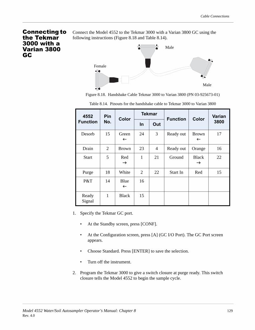
Cable Connections
Connecting to the Tekmar 3000 with a Varian 3800 GC
Connect the Model 4552 to the Tekmar 3000 with a Varian 3800 GC using the following instructions (Figure 8.18 and Table 8.14).
Figure 8.18. Handshake Cable Tekmar 3000 to Varian 3800 (PN 03-925673-01)
1. Specify the Tekmar GC port.
• At the Standby screen, press [CONF].
• At the Configuration screen, press [A] (GC I/O Port). The GC Port screen appears.
• Choose Standard. Press [ENTER] to save the selection.
• Turn off the instrument.
2. Program the Tekmar 3000 to give a switch closure at purge ready. This switch closure tells the Model 4552 to begin the sample cycle.
Table 8.14. Pinouts for the handshake cable to Tekmar 3000 to Varian 3800
4552 Function
Pin No. Color
TekmarFunction Color Varian
3800In Out
Desorb 15 Green 24 3 Ready out Brown 17
Drain 2 Brown 23 4 Ready out Orange 16
Start 5 Red 1 21 Ground Black 22
Purge 18 White 2 22 Start In Red 15
P&T 14 Blue 16
Ready Signal
1 Black 15
Male
Female
Male
Model 4552 Water/Soil Autosampler Operator’s Manual: Chapter 8 129Rev. 4.0

Cable Connections
3. Select method 14 to provide correct polarity settings for the purge ready output. If another method is selected, refer to the Tekmar 3000 Operator’s Manual for additional information.
4. Connect the cable to the Model 4552, sample concentrator, and Varian GC. Refer to the GC and data system operator’s manuals for correct connector locations.
NOTE: Be sure the locking screws on the cable secure the connector to the instrument chassis.
Model 4552 Water/Soil Autosampler Operator’s Manual: Chapter 8 130Rev. 4.0

Chapter 9 Assembly Diagrams
Internal Standard Valve Assembly
Figure 9.1. Internal standard valve assembly
Six-way Valco valve and motor assembly
(03-505879-00)
Rotor with 1-µL internal loop (03-505726-00)
Standard reservoir mount(03-505604-00)
E/i" Teflon ferrule(03-694637-00)
5-mL Reservoir vials
(03-505484-00)
Model 4552 Water/Soil Autosampler Operator’s Manual: Chapter 9 131Rev. 4.0

Assembly Diagrams
Mixing Solenoids and 26-mL Syringe Assembly
Figure 9.2. Mixing solenoids and 26-mL syringe assembly
Vial Sample Station
Figure 9.3. Vial sample station
Syringe mixing manifold assembly (03-505830-00)
Flangeless ferrule and fitting (03-700081-01)
26-mL Plunger assembly w/ O-ring (03-700060-91)
Syringe glass barrel (03-502968-00)
Stir motor assembly (03-505833-00)
SoilVial and upper soil heater assembly(03-505883-00)
Lower soil purge gas needle assembly
(double-ended vial) (03-505463-00)
Water vial cup(03-505451-00)
Model 4552 Water/Soil Autosampler Operator’s Manual: Chapter 9 132Rev. 4.0

Assembly Diagrams
Probe Section and Interface/Transfer Line, Purge Gas Solenoid
Figure 9.4. Probe section showing interface/transfer Line, purge gas solenoid
Soil-purge-gas transfer line and heater assembly (03-700001-01 for Model
4560 or Tekmar 2000/3000)
Water probe assembly(03-505739-00)
Soil probe block heater assembly
(03-505895-00)
Upper-soil-valve heater
(03-700072-01 for SN >13160)
Heated upper-soil-valve assembly (03-700032-00, 03-700039-90)
Soil probe assembly (double-ended vials) (03-700076-91 for SN >13160)Needle sparge probe assembly (03-700077-91 for SN >13160)
Flangeless ferrule (Q/qy") and fitting (03-700081-01)
Model 4552 Water/Soil Autosampler Operator’s Manual: Chapter 9 133Rev. 4.0

Assembly Diagrams
Inside Back Panel
Figure 9.5. Back inside panel
Two-way soil transfer gas solenoid standard mount
(03-505899-01)Manifold mount (03-700111-00)
Three-way pressure gas solenoid standard mount (03-505899-02)Manifold mount (03-700112-00)
Timing pulley (leadscrew) (03-5050363-00)
Timing belt
(03-505477-00)
Syringe and elevator limit switch assembly (03-505273-00)
Solenoid mixing manifold assembly
(03-505831-00)
Single Burkert valve
(03-505720-00)
Helium gas pressure regulator
(03-918707-05)
¼" Motor pulley (03-505429-00)
Model 4552 Water/Soil Autosampler Operator’s Manual: Chapter 9 134Rev. 4.0

Assembly Diagrams
Robotic Arm
Figure 9.6. Robotic arm
Timing belt(03-505384-00)
Motor pulley(03-505393-00)
Up-down motor assembly(03-505884-00)
Timing pulley(03-505363-00)
Motor pulley(03-505393-00)
Timing belt(03-505372-00)
Left-right motor assembly
(03-505880-00)
Gripper block assembly
(03-505844-00)
Timing pulley(03-505363-00)
Front-back motor assembly
(03-505881-00)
Model 4552 Water/Soil Autosampler Operator’s Manual: Chapter 9 135Rev. 4.0

Assembly Diagrams
Model 4552 Water/Soil Autosampler Operator’s Manual: Chapter 9 136Rev. 4.0

Chapter 10 Interconnection Diagram
Beeper
Stir
Ves
taM
CIO
(J1)
Ves
taM
CIO
(J8)
Remote RS232
Ves
taR
S23
2(J9
)
Ves
taM
CIO
(J10
/11)
J25
J22
J21
J16
J17
J13
J14
J9
J7
J6
J10
J11
J12
J15
J18
J19
J20
J23
J24
J30
J29
J28
J26
J27
J1 J2
J4J8
F6
F5
F4
F2
F1
F3
Sam
ple
Pro
beR
eser
voir
Wat
erH
eliu
mW
aste
Upp
erS
oilP
robe
Spa
rge
Tub
eS
oilP
robe
Hel
ium
Wat
erP
rob
eH
eliu
mG
rippe
rS
oilP
urge
Ext
.Spa
reU
pper
Soi
lVal
ve
Fus
eF
6F
5F
4F
3F
2F
1
Am
pera
ge1
Am
p2.
5A
mp
1A
mp
2.5
Am
p1
Am
p1
Am
p
Fus
eTy
pe:2
50V
AC
,2A
GS
ubm
inia
ture
Slo
-Blo
fuse
Hea
ter
Des
crip
tion
Upp
er
So
ilV
alve
Soi
lTra
nsfe
rLi
neU
ppe
rS
oil
Pro
beO
pt.S
ampl
eP
reH
eat
Soi
lSam
ple
Cha
mb
erH
otF
lush
Wat
er
Stir
Spe
e d
J5J1
2J1
1J6
J8D
J8C
J8A
J8B
TS
1
Fro
nt/R
ear
Std
.Val
ve
Left/
Rig
htU
p/D
ow
n
+ -
5049
1450
5240
+ -
- +
- +
- +J1
1J1
0
J8 J1J2
J3(K
eypa
d)J4
J9(L
CD
)
Ves
taM
CIO
5052
49
EPROM
J9LC
DC
ontr
astA
dju
st
5052
49
WA
RN
ING
:S
HO
CK
HA
ZA
RD
Hig
hVo
ltag
e.C
over
sm
ustb
ere
plac
ed.
Model 4552 Water/Soil Autosampler Operator’s Manual: Chapter 10 137Rev. 4.0

Interconnection Diagram
Model 4552 Water/Soil Autosampler Operator’s Manual: Chapter 10 138Rev. 4.0

Chapter 11 Flow Diagrams
Model 4552 Water/Soil Autosampler Operator’s Manual: Chapter 11 139Rev. 4.0

Flow Diagrams
Model 4552 Water/Soil Autosampler Operator’s Manual: Chapter 11 140Rev. 4.0

Flow Diagrams
Model 4552 Water/Soil Autosampler Operator’s Manual: Chapter 11 141Rev. 4.0

Flow Diagrams
Model 4552 Water/Soil Autosampler Operator’s Manual: Chapter 11 142Rev. 4.0

Flow Diagrams
Model 4552 Water/Soil Autosampler Operator’s Manual: Chapter 11 143Rev. 4.0

Flow Diagrams
Model 4552 Water/Soil Autosampler Operator’s Manual: Chapter 11 144Rev. 4.0

Flow Diagrams
Model 4552 Water/Soil Autosampler Operator’s Manual: Chapter 11 145Rev. 4.0

Flow Diagrams
Model 4552 Water/Soil Autosampler Operator’s Manual: Chapter 11 146Rev. 4.0

Flow Diagrams
Model 4552 Water/Soil Autosampler Operator’s Manual: Chapter 11 147Rev. 4.0

Flow Diagrams
Model 4552 Water/Soil Autosampler Operator’s Manual: Chapter 11 148Rev. 4.0

Flow Diagrams
Model 4552 Water/Soil Autosampler Operator’s Manual: Chapter 11 149Rev. 4.0

Flow Diagrams
Model 4552 Water/Soil Autosampler Operator’s Manual: Chapter 11 150Rev. 4.0

IndexAAdjust Counters 60Altitude 3Auto 8, 39Auto Calibrate 62Automatic Mode 1Autorun Operation 39Autosampling 39Aux Output 73
BBackflushing the Water Probe 44Backspace 8Bar Code Scanner 77Beep on Error 78Blank/Wash Bottle
Setting Up 16
CCalibration Test 62Clean Syringe 61Coolant 3
DDelayed Start 40Desorb Drain 72Dimensions 2
EElectrical Connections
Setting Up 15Emergency Stop 72Enter 8Equilibrium
Zone Station 10Escape 8Extra 72
FFlush 8, 42Flush Mode 1Flushing the Syringe 42Four-Port Fitting
InstallingTekmar 2000 34Tekmar 3000 29
Four-way Injection Valve 18
GGas Connections
Setting Up 15Gauge, Pressure 7General Configuration Screen 23Guidelines
Method Programing 50
HHeater Cartridge 25
Installing 25Helium Connection 9Helium Supply Pressure 15Hold State 44Hot Water Rinse 77Humidity, Relative 2
II/O signals 15Ignore No Vial 77Ignore Vial Type 77Injection Mark 73Input Signals 72Interface Cables 15
KKeypad 7Knockoff Clearance 69
Recalibrate 69
LLCD Screen 7Liquid Coolant 3Loop Calibration 71
MManual 8, 40, 41, 42Manual Calibration 63Manual Flush Sequence 42Manual Mode 1Manual Run 41Method 8, 45, 49Method Blanks 49
Programing 49Method Parameters 45Method Program
Soil 50Water 50
Method Programming Guidelines 50
NNeedle Sparge 77
OOperating Modes 1Output Signals 73
PParameters
Sample Method 45Pause/Stop 8, 44Pausing 44
151

Power 9Precautions 4Pressure Gauge 7Priority Run 40Priority Sample 41Probe, Soil 11Probe, Water 11Purge Gas Input 9Purge Gas Line
InstallingEclipse 19Model 4560 26Tekmar 3000 32
Purge Gas LinesInstalling
Tekmar 2000 36
RRegulator 7Remote I/O 9Remote I/O Connector Signal Pin-Outs, Model 4560 111Remote RS-232 9Requirements 3
Gas 3Power 3
Reservoir Bottle 16Rinsing the Sparge Tube 43Robotic Arm 10
SSample Capacity 3Sample Method Parameters 45Sample Sequence
Water 53Sample Stir Motor 10Sample Tray 7, 10
Setting Up 16Sample Valve, Model 4560
Installing 27Screens
General configuration 106, 108Setup Specifications
Model 4560 29Tekmar 2000 38Tekmar 3000 34
Shipping Position 60Single 40Size, Sample 3Soil Method Program 50Soil Probe 11Soil Vial 73Soil-Purge-Gas Transfer Line
InstallingModel 4560 25Tekmar 2000 35Tekmar 3000 30
Soil-purge-gas Transfer LineInstalling
Eclipse 20
SoilVial 11Sparge Tube
Draining 42Rinsing 43
Standard Clearance 70Recalibrate 70
Standard Valve 11Standby 72Start Purge 73Stop, Emergency 72Stopping 44Syringe 10
Flushing 42System 8System Calibration 61System Diagnostics 71System Hold 44System Maintenance 59System Parameters 73System Status 58Systems 77
TTemperature
Operating 2Storage 2
Thermocouple 25Installing 25
Three-Port Fitting, ReplacingTekmar 2000 35Tekmar 3000 29
Transfer Line FritInstalling 84
Tray Coolant 9Type, Sample 3Type, Vial Identification Sensor 11
VValve, Standard 11Vial 66Vial Checks 77Vial Count 60Vial Gripper 10Vial Type Identification Sensor 11Vial, VOA 11VOA 11
WWash Bottle
Refill 16Waste Block 60Waste Lines 9Water 67Water Connection 9Water Method Program 50Water Probe 11
Backflushing 44Water Reservoir 9Water Sample Sequence 53
152

Water Transfer LineInstalling
Eclipse 21Model 4560 28Tekmar 2000 37Tekmar 3000 33
Weight 2
153

154