
Model 3550 Microplate Reader - Bio-Rad | Products for Life ... · The Model 3550 Microplate Reader...
33
Model 3550 Microplate Reader instnxtion Manual Catalog Numbers 170-6601,17&6602 5;o-Rad ,Laboxatorie:s, 2WlC~ Alfred Nobel Drive, Hercules, CA 34% ‘” c i-‘!?u:;t? t”5 ‘0) 741-,I000
Transcript of Model 3550 Microplate Reader - Bio-Rad | Products for Life ... · The Model 3550 Microplate Reader...
Model 3550 Microplate Reader
instnxtion Manual
Catalog Numbers 170-6601,17&6602
5;o-Rad ,Laboxatorie:s, 2WlC~ Alfred Nobel Drive, Hercules, CA 34% ‘” c i-‘!?u:;t? t”5 ‘0) 741-,I000
Table of Contents
Section 1 1.1
Introduction Accessories for the Model 3550 Microplate Reader
section 2 Product Description 2.1 Extemal Features 2.2 Block Diam of Optical System 2.3 Membrane Keypad
Section 3 3.1 3.2 3.3 3.4
Operation Contents of the Shipping Container Initial start-up Setting the System Parameten Conceptual Operation of the On-Board Software
Section 4 4.1 4.2
Analysis Protocols Selecting aa Analysis Protocol Setting the Analysis Parameters
8 8 8
!3ection 5 Formatting 11 5.1 Opening a Format 11 5.2 Assigning Blanks . 11 5.3 Assigning st3ndards 11 5.4 Setting tbe Values of Standa& 12 5.5 Assigning Samples 12 5.6 Editing Formats 12 5.7 Removing Well Designations 12
S&ion 6 6.1 6.2 6.3
Viewing and Editing Reports Types of Reports Viewing the Reports on the LCD Screen Editing Reports
I
13 13 14 14
!%ction 7 7.1 7.2 7.3 7.4 7.5 7.6 7.7 7.8
Priatiq Reports Automatic Report Printout PRINTREPORTS PRINTALL PRINT ANALYSIS PRINTFORMAT PRINTDATA
Rinting the Raw Data of Plates Read by Remote Control
15 15 15 15 15 15 15 15 15
section 8 Usiq tb Data Buffer 8.1 Recalling Data From Memory 8.2 Dekting Individual Data Seu 8.3 Clearing the Memory 8.4 Transmitting Data
16 16 16 16 16
Se&on 9 9.1 9.2
Chmging the L,amp and Installing Interference Filters Changing the Lamp Insding an Iaterfemce Triter
18 18 18
section .lO ll-ouble3hooting 19
Won ll SpSitlcrtioru .ll.l TechhI Specifiutions
21 21

!htion 12 Computer Spfxifications 22 12.1 RS-232-C Interface Specifications 22 12.2 Command Language 22 13.3 Helpful Hints for the Command Language 25
Appendix A Sample Report Documentation 26
Sect/on 7 Introduction
The Model 3550 Microplate Reader is a vertical pathlength photometer which measures the aJ~sortxnces of the contents of the wells of a 96 well microtitration plate. Single or dujl wavelength measurements can be made, and absorbance values are measured to three decimal places.
‘I& Model 3550 Micruplate Reader can be programmed by entering commands through the membrane keypad to select analysis parameters, de& plate formats, and select report types and print options. Four different npons can be gener- ated: absorbance, limit, math, ~JXI evaluation (which includes extrapolation of sample concentratioas from a linear rcgrcssion of standard values). Analysis parameters. plate formats, and reports which include aa 8 x 12 presentatioa of data cau be viewed oa the liquid crystal display (LCD). The instrument’s memory has the capacity to stoic 9 analysis protocols, 9 formats, and 25 sers of plate data For hard copy, the Model 3550 Microplate Reader can be interfaced with an optional printer such as rhe Epson FX 850 (catalog number 125-1155) or Epson EX 800 (catalog number 125-1230).
. An optional plate stacker and loading mechanism with 25 plate capacity (catalog number 170-6612) is available for lab- oratories requiring high thougl~put. The Model 3550 Microplate Reader includes a built-in RS-232-C serial interface deticc for convenient computer interfacing with tbe Microplare Managei sod Kinetic Collectof software for the KEM PC or Apple Mac&o& computer, which offer complete analysis programs.
1.1 AccessoHos for ttte Model 3550 Miciopla te Reader
RQdUCt Catalog Number
540 m~bt.erferena FYter 170-6634 550 mn Interfercna Fdter 170-663s 57OnmInterfercDccFiltcr 170-6636 630nmInterfercntxFilter 170-6637 Automatic Stack bading Mechanism 170-6612 StackLoaderMagazines 170-6613 Kinetic colkctof~tosh softmrc 170-661s Kinetic colk?uof/Pc softwau 170-6616 Microplate Managcf/Pc software 170-6617 Microplate hUagef/Mtwzintosh Sofnvan 170-6618
1
Section 2 Product Description
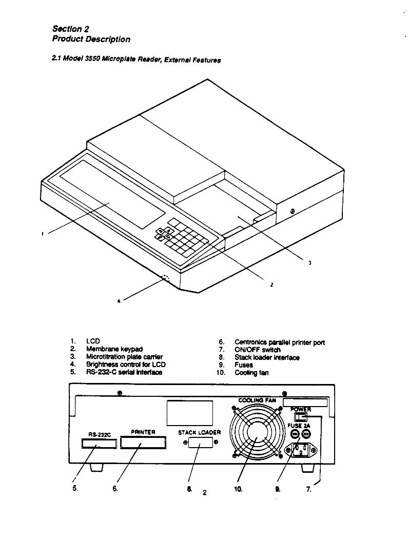
2 1 Model 3550 Mlcrophte Reader, External Features
1. LCD 6.
:: Membrane keypad 7.
Centronics parallel printer port ON/OFF switch
Microtitmtion piate camier 8. stackloadwintefface 9. Fuses
10. cooling fan
STACK LOADER
5. 6. 8. r) 10. a 7.
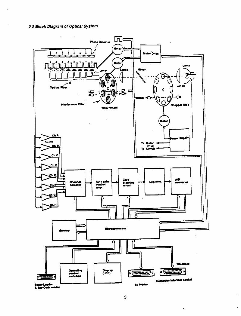
2.2 Block Diagram of Optical System
, ,
nnnnnnnn
II ( I! luuy+.--jd
A i &v gral Flbu
hlufuanoFltlr - ’ -
2.3
.
.
.
.
.
.
.
.
.
.
.
.
Membrane Keypad
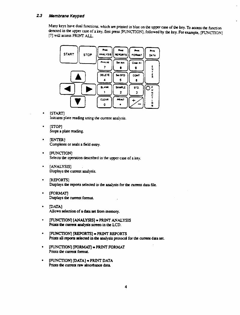
MAY keys have dud fusions, which are printed in blue on the upper case of the key. To access the hnctjon kmed in the upper me of a key, first press ACTION], followed by tbe key. For example, SCION] [7] ydl access PRINT ALL.
Initiates plate reading using the current analysis.
[STOP] Stops a plate reading.
Completes or seals a field eoay.
Selects the operatioo described in the upper case of a key.
[ANALYSIS] Displays the curreot analysis.
IREPORW Displays the reports selected in the analysis for the current data 6le.
Displays tbe cumxt format.
Allows select.ioo of a data set from memory.
pJNcrIoNj [ANALYSIS] = PRINT ANALYSIS Rinuthe~atxilysisscreenintheLCD.
~CT’ION] [REPORTS] = PRINT REPORTS P&S &I rrporrs S&M in the dysis protocol for the cumnt data set.
FLJNCIIONJ [FORhMJ-PRINTFORMAT Priots the current format.
FUNCI’IONj IDATA] = PRINT DATA Ptiots the culTcot raw absortmce data.
4
.
.
.
.
.
.
.
.
.
mCI-lON] [I] = BLANK Used to define blank wells in a plate format.
[FUNCTION-J [2], = SAMPLE Used to define sample wells in a plate format.
~CI-IONI [3 J = STANDARD Used to define standard wells in a plate format.
[FuNCllON] [4] = DELETE Flags data points as oudiers or reinstaBs data points previously flagged as outliers. Also, changes well designa- tion in format to undesignated state.
fFtJ’NCI’I0N-j [5] = SET STANDARD Displays the set standards screen
[NNCI-lON] [6] =CObITINUE Used to view the remaining portions of reports which do oat fit on the LCD. Pressing these keys will scroll to tbe next portion of the report; if pressed while viewing the end of a report, the LCD scrolls to the beginning of the report.
WCI’ION] [7] = PRINT ALL Prints all the repons selected in an analysis for each data file read and stored in the data buffer.
~ClTONJ [S] = SET SYSTEM Displays the set system parameter saeen.
puNcn0N-J [9] = CLEAR ALL Clears all data files tirn memory.
IFuNmoNl LOI = CLEAR Clears selected data files, formats, and standard concentration tables tirn memory, and returns them to the default settings.
[RTNCT’ION] [.I = PRINT Priots the curreot information in the Lm, like PRINT SCREEN on a computer.
[+/-I Plus or minus sign key. Plus is the default: press ~CTIONI to access the minus sign
@9 Numeric keys. Additiooal fuoctions, deooted io the upper case. are accessed by &t pressing [NNCIlON].
. . Decimal point key
5
Section 3 Operation
3.7 Contents of Shfpplng Container
The Model 3550 Microplate Reader is supplied with the following items. Contact your local Bio-Rad representative if aoy of these items are missing.
Model 3550 Microplate Reader Two 2 amp fuses Instruction manual Dust cover Power cord
3.2 lnitlal Stsrt-Up
1. Place the instrument on a clean, sturdy table or bench. Maintain the instrument in a dean, relatively dust free environment to insure maximum performance.
2. Inspect the outside of the unit for any signs of damage. If damage is found, cootact your BieRad teptesenta- tive. In the USA, call BieRad Technical Service at I-800.4BIORAD. Complete the Warranty Registration Card and return it IO Bio-Rad Laboratories.
3. Connect the power cord to the back of the instrument. Before connecting the instrument to the main electrical supply, check to make sure that the AC voltage is appropriate for the instrument.
4. Turn on the power switch oo the rear panel. An initial self-diagnosis is conducted, which requires about 1 minute. Allow the instrument to warm up for 15 minutes before reading to estabhsh thermal equilibrium. The time remaining in the warm-up period is displayed in the lower tight LCD. Programming operatiolrs and plate reading may be conducted during the warm-up period. However, the ptinted reports of any readings taken prior to completion of the warm-up period will note ‘the plate was read before completion of warm-up’.
5. Adjust the brightness of the LCD with the wheel under the right side of the tint panel.
3.3
1.
2.
3.
4.
5.
Setting the System Pammeten ,
The system parameters are accessed in the set system screeo, by pressing Set Sys. ([FUNCTION] [8]). Remember to seaI each change by pressing lENTER].
Choose the date format to be displayed on the LCD and hard copy by pressing the right or kh arrow keys until the ptefetred fnnnat is enclosed in brackets. You may choose either the month/day/year (mm/dd/yy) or the day/month&ear (ddhm/yy) format.
Set the date by pressing IENTER] until the tumor rests on the value to be changecd; ener the correct value from thekeyp4tharpmss@NTER]tosealtheentry.
Set the cmea the io tIx 24 hour format. For example 1:30 PM is entered as 13:30.
You may chtmge the defauh analysis, which is the analysis that appears upon power up.
If custom filters am instaRed, or the positioo of the 6lters in the filter wheel is changed, the information should be updated on the set system sueen. Press lXNTER] until the cursor rests on the wavekngth value of the filter wheel positioo you wish to change. Enter the correct wavelen& and press -1. llre changes will appear on the analysis sctcen. Press [ANALYSIS] and vetify th3t the filter wheel positiorrs and comsponding wave- lengths are correct. (See Section 9.2 for specific insauctions on installing 6lten.)
6
3.4 Conceptua/ Operation ot the On-Board Softw8re
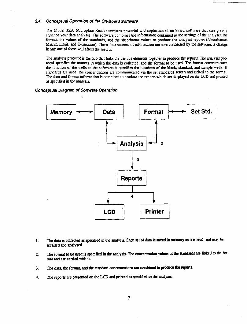
The Model 3550 Microplate Reader contains powerful and sophisticated on-board software that can greatly enhance your data analyses. The software combines the information contained in the settings of the analysis, the format, the values of the standards, and the absorbance values to produce the analysis reports (Absorbance. Mat.& Limit. and Evaluation). These four sources of information are interconaected by the software; a change io any one of these will affect the results.
The analysis protocol is the hub thar links the various elements together to produce the reports. The analysis pro- tocol specifies the manner in which the data is collected, and the format to be used. The format communicates the function of the wells to the software; it specifies the locations of the blank, standard, and sample wells. If standards are used, the concentrations are communicated via the set standards screen and linked to the fonat. The data atxl format information is combined to produce the reports which ate displayed on the LCD and printed as specified in the analysis.
Cunceptuel Diagram ol Sottware Opera tlon
Reports
1. Tbe data is collected as specified io the analysis. Each set of data is saved in memory as it is read, and may bc YecalM sod analyzed.
2. The format to be used is specified in tk anaIysis. The concentratioa values of the stathds ate linked IO the for- mat and are carried with it.
3. l’le data, the format, and the star&d concentrations are combined to product the nporW.
4. The reports arc preseoted on the LCD and printed as s@Bed in tk anaiysis.
7
Sect/on 4 Analysis Protocols
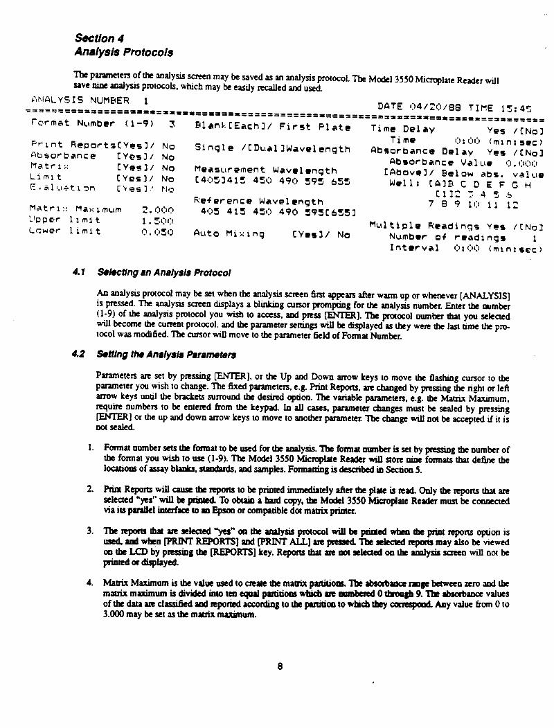
l%e parameters of the analysis screen may be saved as an analysis protocol. The Model 3550 Microplate Reader will save oine analysis protocols, which may be easily recalled and used.
nrMLYSIS NUMBER 1 ‘======IP’lf=‘PDIIII~==--= DATE 04/20/88 TIME 15:45 ====----------------,,,,,,,,, ---““‘-““‘-‘---------= PPPlt===t’p=fr=fDf’=rp==
fwmat Number (I-9) 3 BlankCEachl/ First Plate
Print Report5CYesll No Absorbance CYesl/ No
Sinqle ICDuallWavelenqth
Matr I i: CYesl/ No Llmlt [Yes31 No
Measurement Wave1 enqth
E.aluatlon t4053415 450 49f3 595 653
Ckosl j PI0
Time Del ay Yes /CNol Time 0: 00 (mr n: set )
Clbsorbance Delay Yes /CNol Absorbance Value I:, . c:~c:I~:l
CAbovel/ Below abs. value Well: CAIE C D E F G H
Cl32 1 4 5 .5 7 8 9 10 11 12
Matrl:: Maxim~lm 2. (:,(:I0 Reference Wavelength
LIpper 1 i ml t 40s 415 450 490 595CbS53
1 . 5l:H:l Lower 1 iml t 0. r:,51:, Auto Mixing CYesl/ No
Multiple Readings Yes /CNol Number of rcadrngs 1 Interval O:OO (mln:sec)
4.1 Sekting an Analysis Protocol
An analysis protocol may be set when tht analysis screen &it appears after warm up or whenever [ANALYSIS] is pressed. The analysis screen displays a blinking cursor pompting for the analysis number. Enter the number (l-9) of the analysis protocol you wish 10 access, and press @NTER). The praaoi number that you sckctcd will become the cumol protocol, and the parameter settings will be displayed as they were the last time the p’~ taol was modi6ed. Tk CUrSor will move 10 tbe parameter field of Format Number.
4.2 Setting the Analys& Parameten
Parameters arc set by pressing -1, or the Up and Down arrow keys to move the flashing cursor to the parameter you wish 10 change. The fixed parameters, e.g. print Reporu, are changed by pressing the ri&t or left arrow keys until the brackets surround the desired option. The variabk parameters, e.g. the Matrix Maximum, require numbers to be entered fiorn the keypad. In all cases. p~vneta changes must be scaled by pressing -1 or !he up and down arrow keys lo move lo another parameter. Tbe change will not be accepted if i! is noIseakd.
1. Fomrat number as the format to be used for the analysis. The format number is set by pressing rbe number of tbe format you wish 10 use (l-9). Tk Made1 3550 Microplate Reader will store nine formats that define the loatioos of =y blanks, m, ti samples. Foxmaaing ia de&bed in Section 5.
2. PrinRepomwiUuusctbcrrporutokprinadimmedirOly~~tbeplauisled.Onlytberrporu~arr seleacd ‘yes” will k p&cd To obtain a haA copy, the Model 3550 Microplate Reader must be connected via iu panikl intcrfatx to ID Epson or compatibk dot matrix printer.
3. ‘Zbcrrpomlbarycseleaed”yer”~the~~prococolwillkpriaed~tbcpriw~opionis used~w~nlPRINTREPOKIS]lod~RINTALL]yepnsscdTbcslcctcdrrpoltsmayllsobeviewed cn,tbcLCDbyprrssirrgthc~~]key.RcponsthiuIrcootscleaedoatbcrcr;rlysisscrreowillootbe pioud or &piayed
4. Matrix Maximum is the value used 10 create tbc matrix p&o=. ‘I& Mm rrngc besweeo zero and the matrixmlximumisdividcdinlotcneq9?1przritiolrswbicb~PlunkrcdO~gb9.Ibcrbsorb~values oftbtdatlMdaSSifiedmdrrporiedaccordingtothcpPreitiartowhicbtbeycarrspoodAnyvalue~omOto 3.000 may be set as tk maaix maximum.
5. Upper and Lower Limits define the boundaries of the Limit Repon. Absorbance data that fall within be boundaries are displayed as asterisks, data below or above the limits are represented by minus or plus signs, respectively. Limits from 0 to 3.000 may be set. However, the lower limit may not exceed the upper limit.
6. Blank Each/First plate. Blank Each Plate specifies that the blank value will be determined for each plate inde- pendently. Blank Fast Plate specifies that the blank value of the first plate of a series will be used for all the plates in the series. The Frnt Plate is the plate to be read after the analysis is selected and set. The blank value may be negated by deleting the blank wells Erom the data set of the lirst plate. (See Section 6.3 for informauon on editing data) When the blanking mode is changed from Blank Fmt Plate to Blank Each Plate, the blank value of the first plate is deleted born memory so that it will nof be used for subsequent plates. ‘IIe straregy for using this mode is as follows:
Set the h3lysis screen for the assay:
Set the format number to the format of tbe first plate (which contains the de&d blanks).
Set the blanking mode to Blank First plate.
Read the fUst plate.
Return to the Analysis screen and change the format number to the format of the subsequent plates.
Read all subsequent plates.
5. Set the blanking mode IO Blank Each Plate after all of the plates have been dad. Doing so will discontinue the blank value of the 6rst plate. (Turning off the power to the instnJment will also discontinue the blank value of the first plate.)
7. Single/Dual Wavelength specifies the optical mode used for the analysis. Single wavelength mode reads the absorbance of the wells at the measuremeot wavelength, which ideally is the wavelength of maximum absorbance of the substrate. Dual wavelength mode teads the absorbance at the measurement wavelengtb and the reference wavelength The reference wavelength should be the minimum absorbance for the subsuate, essentially the background absorbance. The dual wavelength mode subtracts the reference absorbances horn the measurement absorbances to reduce artificial well IO well variation.
8. The values listed for the measuremeot and reference wavelengths are entered ia the Set System screen. If cus- tom filters are installed or if the titer positions arc changed, the information in Set System should be updated as described in Section 3.3.
9. Auto h4ix will agitate&e plate for 3 seconds befotc reading to disperse the substzate and product, and to pro- mote even wetting of the wells.
10. lime Delay specifies that the reading of the plate will be delayed by the specified time aher pressing [STARTI. To use the time delay:
Select “yes” for Tie Delay.
Enter the de&e minutes of delay, from 0 to 99 minutes.
Enter the de& secoads of delay, fmm 0 to 59 seconds.
Press [STARTI whea you arc ready to rrad the plate. The LCD will display the time nmaining until the plrlte is read.
11. Absorbance Delay will deIay data collection until the specified weil reaches a speci&d absorbanoe. To use the absorbance delay:
9
Select “yes” for Absorbance Delay.
Set the threshold absorbance value.
Set “above” if you want to read the plate when the absorbance of the well uoeeds the threshold absorbance. Select “khf’ if you want to read when the absorbance of the well falls below the UucsboId value. For most conventional ELI% using alkaline phosphatase and horseradish peroxidate, ‘above” is the proper selection. Set he row and column co-ordinates of the target well.
Press [STARTJ when you are ready to begin monitor3g the plate. The instrument will repeatedly read the plate until the absorbance delay conditions are met, then the absorbance data will be collected and displayed.
Tie and Absorbance Delays may be set simultaneously. ‘Time Delay will count down 6zst, tbeo Absorbance Delay w-ill be activated
12. Multiple Plate Readings may be used to record sequential readings of a single plate for kinetic or other analy- SeS.
Select “yes” for multiple plate readings.
Set the number of times the plate will be read, from 1 to 25 times. Tbe maximum number of repetitions will depend on the memory available. Ihe LCD will insnuct you to delete a f%(s) or clear the buffer if necessary. See Section 8 for more information on the memory buffer.
Set tk interval between readings by entering the minutes and seconds desired. The instxument defaults to the minimum reading time for the given reading parameters, and will not accept inter-& less than the minimum mdiogtime.
PaWt&C Single wavelength Single wavelength with mixing Dual wavelength Dual wavelength with mixing
12 seconds 15secQnds 22 secmds 25 seconds
The time that you set will be the actual time between sequential teadings, including the tie required to read the plate.
Note: When using the multiple reading mode, it is possible to set reading conditiorrs that cause the actual time required to tead to be greater than the multiple reading time inerval. For exampk, setbg the muitipk rrrding interval for 12 seconds, and changing the reading mode from single wavelength to dual wavelet@ aeatea a axrfRct with the muluple reading interval. When a co&ct occurs, the multiple reading interval will be replaced with the lowest possible default value, and the LCD will display the following message: “Wamiog! The muhipie reading time itttewd has been replaad with the default by a related field entry.” Press any key to clear the wuning message. l%is message will only appear wko tk multiple nading mode is in use, that is wheo YES is sekcted for the muhipk reading mode.
10
SectIon 5 Fotmattlng
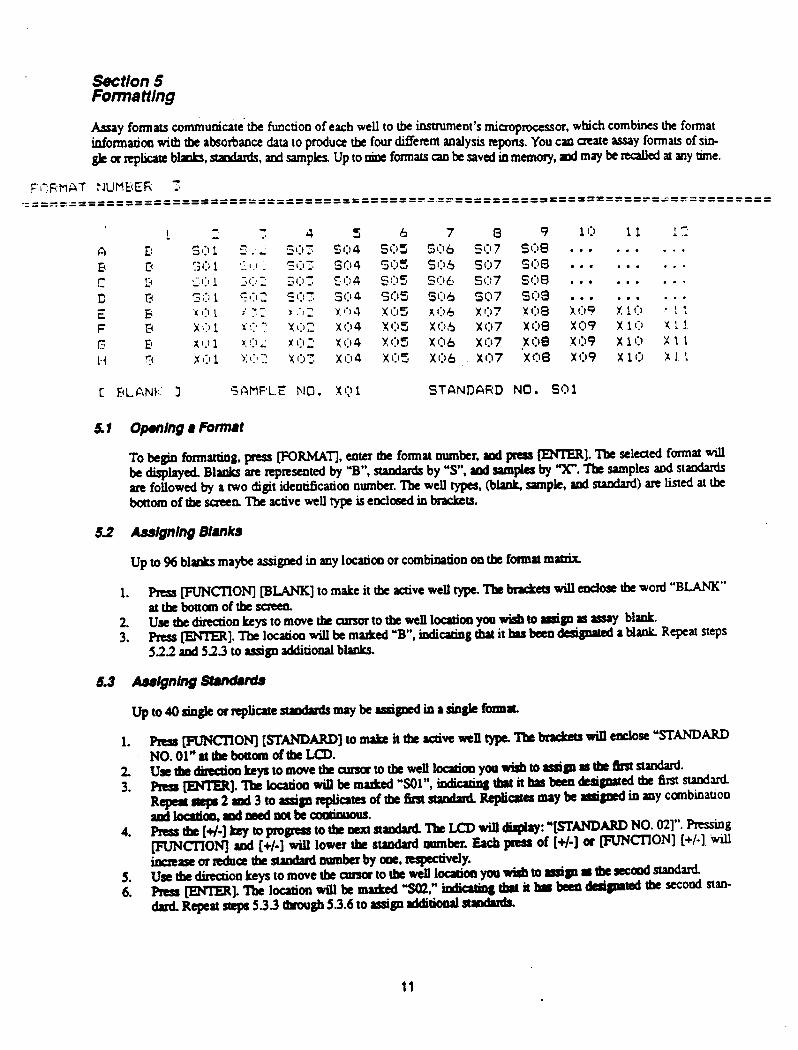
My formats communicate~tbe functioo of each well to the insttumeot’s microprocessor, which combines the format infotmatioa with the absoxtmce data 10 produce the four different aoalysis reports. You can create assay formats of sin- gkanpliutcMPb,standards,andsampksUpto~formatscapbesawdinmemoy,pdmayk~~~y~e.
F’hF;MAT :JUMBEF\: I: .===-===========- -========-===========p= ‘----“=-=========‘I========== ---e--
C FLANI:.: 1 5AtlPL.E NO. X()1 STANDARD NO. So1
51 Opaning 8 FMn8t
To begin folmatting, press ~RMAT], enter t!le format number, aui pIeSs -1. The selected foxmat will be displayed. Blanks arc rep~sented by ‘B”, standards by ‘s”, and sam@es by “X”. Tk samples sod standaxds are followed by a two digit ideotikatioo oumber. The well types, (blaak, sample, attd stat&d) are listed at the bottom of the ~a l%e active well type is enclosed in brackets.
52 Asdgnlng Bhnks
Up to 96 blanks maybe assigned in any location or combination oa tk fomrat math
1. Press MCTIONj PLANK] to make it the active well type, The bxa&ets will eadose tbe word “BLANK’ attkbottanoftbesueen.
:: UserhedirrcaIonhystomavetbecmsortothtweIllocltiooyoowisbu,rssiaarssly blank. Press @NlER]. The location will be marked ‘B”, indicating that it brs been design&d a blank Repeat steps 522 and 523 to assign additional blanks.
63 Adgntng ShnchM
Upto40~glearrrpucue~~berssigncdiarsingtefomrr
1. prrS~ON][sTANIlARD]tomrLaittbcrcriveanlltypc’Lbcbnricctsrsin~sc’sTANDARD NO.Ol”rttbebottanoftheLCD.
4’ ~~;~~~~&~ turndud ‘be LCD will display: “[STANDARD NO. 021’: F’reskg [FUNCTION) and [+/-I will lower the standad mmber. Each pms of [+/-I or [FUNCTION] [+/-I. ‘idI iflCE+scoHUhl~the~DPmkrby~,~spcctively.
5. UsctbtdirrcdonLcystomovecbtcmsatotbtPnn~~yolrvbbto~~rrbewcoodstaodard 6. Prrss~].‘lbelocrtioa~km~~,“~tbur~~~~~tkxcoDdnaa-
dad. Repeat steps 533 through 53.6 to rssig~ rddifhnal nradrrds.
11
5.4 Setting the ValueS of the Standards
l%e value of the assay standards must be communicated to the microproassor in order for it to perform the Evaiuatioo Report. This is achieved by entering the standard values in the set staodatd scRen
1. Verity that the analysis and format numbers are set properly: Press [~fiFJSl, enter the analysis number if oecessq, and press IENTER]. Enter the comet format num- ber if wcCssaty.
2. Press FUNCI'IONJ [SET STANDARDS]. The cursor will be located at the envy field for tbe value of the 6Jst standard
3. The conceoaation values of standards are set in scientik notation. Fm enter the mantissa value, including the decimal poiot, from the keypad. Press the [+/-I key or the IRMCIION) [+/-I to enter the sign of tbe expooeot, and eater the value of the expo- trot. PRss ENTER to seal tbe transaction and advance to the next standard. Repeat this step until aU of the standard values are set.
4. ‘he LCD will display eoay fields for 20 standards. lf your format has more than 20 standards, uress ICON- TIME] to view a& Set th; remaining envy fields.
.I .
Asslgnlng Sump/es 5.5
5.6
Up to 96 singIe or replicate samples may be assigned in a single format. Press WClION] [SAMPLE] to make it the active well type. The remaining procedures for assigning samples are analogous to those for assign- ing standards. see sectioo 5.3.
Editing Formats
Select tbe proper well type and number, move the cursor to tbe well location that you want to chaoge, and plrss @NTER]. For exampk, if you want to change a well designation to Sample 5, you would:
1. Move the curSor to tbe well location to be edited. 2. Rss [RMCTYON] [SAMPLE]. 3. Adjust the value of the sample to 5 by pressing the [+/-I key. 4. Press IENTER].
5.7 Removing Well l%sIgnations
Any well designatho may be changed to an undesignated state to indicate that tk well has oo function in the assay. For exampk, Zu empty wells would be set as undesignated as follows:
1. Move tk cutsor to the well location, 2. Ress MmON] IDELETE]. The well location will display thee dots to indicate that it is uudesignated
The nsuits of utxkiptcd wells are displayed in the raw data set but not in rhc reports.
12
Section 6 Viewing and Editing Reports
6.1 7’ypes of Reports
‘Ibe AbSOrbMcC Report displays the blank subtracted absorbance values. The mean blank value is subtracted from ~ 96 raw absorbance values. If the Blaok Each Plate opth is used, the blank v&e is he mean absorbance vak of the blank wells assigned in the format. If the Blank Fit Plate option is used, the blank value is the mean absorbance value of the blank wells of the first plate in the series.
The Mauix Report divides the absorbance range between zero and the matrix maximum into ten equal par& tioos, which are numbered 0 through 9. The absorbance values are classified and reported according to these partitions. The matrix maximum may be set on the analysis protocol and when the report is viewed on the dis- play.
Tbe Limit Report classifies the absorbance data according to a single partition defined by the upper and lower limits. Absorbances within the limits are displayed as astetisks. Absorbances above or below the limits are dis- played as plus signs or minus signs, respectively. The limits may be set on the analysis protocol, and whn the report is viewed on the display.
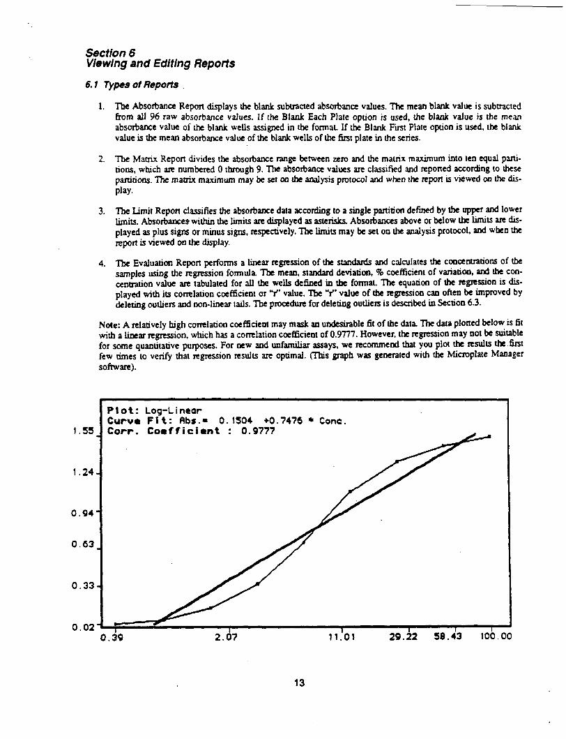
The Evaluation Repon performs a linear regression of the standank and calculates the coocentrations of the samples using the regression formula. Tbe mean, standard deviation, 8 coefficient of variation, and the con- centration value are tabulated for all the wells defined in the format. The equation of the regression is dis- played with its conelatioo coefficient or V’ value. The ‘Y vaiue of the regmsioo can ofteo be improved by deleting outlien and non-linear tails. The procedure for deleting outliets is described in Section 6.3.
Note: A relatively high comlatioo coefficieot may mask an undesitable fit of the data. The data plotted below is fit with a linear regression, which has a correlation coefficieot of 0.9777. However, the regression may not be suitable for some quantitative purposes. For new and unfamiliar assays, we recommend that you plot the results the 6rst few times to verify that regression results are optimal. (This graph was generated with the Microplate Manager
1.24
0.63
Plot: Log-Linear Curum Fit: Abr.- 0.1504 +0.7476 * Cone.
0.39 2.07 11.01 29.22 58.43 100.00
13
6.2 Wewlng the Repotis on the LCD D&play
1. Only the reports that are selected “yes” on the analysis protocol may be viewed on the display. Check the anal- ysis protocol to venfy that the reports you wish to view am selected.
2. Ptess WORTSj to view the first report selected “yes” in the analysis. prty [REPORTS Jagahtoviewthe second selected repon, etc. The reports sequence is a loop, which will show ert, sekcled nport in tum as you to press (REPORTS].
6.3 Edltlng Reporis
The raw data may be e&ted to remove errant data or outhers. Non-linear portiom of the m curve may also be removed 10 improve the curve ht. ‘Ibe taw data may be edited when it appeaxs on tbe screen, immediately after reading the plate, or when the data is recalled from the memory.
After each plate is read, or when data is recalled kmt memory, the raw data is displayed with the cursor flashing oo well A- 1. Move the cursor to the well location you wish to remove. then press mCTIONj ~EIJXE]. The value of flagged data will be replaced by a dot oo all reports, and the data will not be used in the reports or calcu- lations. Flagged data may be reinstated by repeating the editing pro&urns. Move tbe cursor to the value you wish to reinstate and press IFUNCTION] (DELETE]. The original absorbance value wiU mppear and will be used in all feports.
Note: Ibe data cannot be edited immediately after reading when the Multiple Plate Reading optioo is used. Data born multiple plate readings may be recalled kxn memory and edited. See Section 8 for more infonnauoo on usiog the memory buffer.
14
Section 7 Printing Reports
The Model 3550 Microplate Reader offers many convenient methods for printing your results. See Appendix A for a sample of the hard copy produced by the Model 3550 Microplate Reader.
7.1
7.2
7.3
7.4
7.5
7.6
7.7
Automatfc Report Printout
Selecting Print Reports in the analysis protocol will automatically print all the reports selected “yes” tier the plate reading is completed. When the Multiple Pfate Reading option is used, printing will commence after the series of readings is completed. See Section 4 for more information on setting the analysis protocol parameters.
PRINT REPORTS
Prints all reports seleaed in the analysis protocol for the cunent data set.
PRINT ALL -
Rim all selected reports for all tbe data sets read and stored in the memory, using the current analysis protocol. Make sure that the desired repons are selected.
PRINT ANALYSlS
hints the current analysis protocol.
PRINT FORMAT
Prints the CurrerJt format.
PRINT DATA
Prints the curfent raw data.
prints the rhe current tiomratioo on the LCD display.
7.8 Ptinting the Raw D&a of Plates Read by Remote Control
‘Ilx Model 3550 reader will p&t the raw data of a plate read via mote computer control using the following pl-ocedure:
1. Verify that tJ3e printer is propcriy connected to the reader. 2. Press the vCrIOw[.] or Print key immed&& after each plate is xead via remote computer conuol.
Note: Occasionally, the keyboard may be locked because the “AQ” command has ban issued by the bost computer. In this event, tht keyboard may be nkased by pressing the STOP key. (Note: It is not advisabk to perform this operation when using rhe Kinetic Collector sofiware or Multiple Plate Reading Mode of the Microplate Maaager software. ;LS pressing the ‘!STOP key will discobme the kinetic or multiple plate rrading.)
15
Sect/on 8 Using the Data Butler
The Model 3550 Microplate Reader is equipped with battery backed-up memory, which will store 25 sets of data. Each plate is issued a number (l-25) as it is read. l%is numkr appears at the top of the display, and is printed in the kader of every report ‘Ibis oumkr corresponds to the position of the data set in the memory buffer. The memory can k thought of as a rack of 25 slots with the capacity for one data set per slot. The data can k thought of as cards that are inserted in the slots as they are saved Every plate is saved in the memory as it is read, and is assigned the 6rst available slot in tk nckuntilalltheslotsarefull.
When the memory is full, the display will present a message instructing you to delete a plate(s) born the memory or clear the memory completely. A similar message will appear wkn using the Multiple Plate Reading option if the avail- able memory is insu5cient to store all the data sets in the series. When a 5e is deleted, it cannot k retrieved. Data sets can k deleted from the any position in the rack. For example, if data set 12 is deleted, the next plate to k read will be saved iu slot 12 in tk memory. This method allows you to read another plate without disturbing tk order of the nmaining data sets in the memory.
Wkn zeadiog a series of plates, you may prefer to save them as a continuous series in tk buffer. If sufficient space is not available, you may dekte tk required number of cootinuous data sets born the memory. For example, if the memo- ry is full, and you wish to save five tiles continuously, you must delete five continuous data sets (plates 6-10, or 20-25, etc.). Often, it will k more convenient to clear the memory entirely. You may find it desirable to document your results as sooo as possible, so that you can clear the memory and not worry about losing data. However, keep in mind that wko a data set is deleted, you cannot get it back.
8.1 Roc8lling D8ta trom Memory
The raw data of any plate may k recalled by pressing DATA, entering the plate number. and pressing ENTER. The raw data set wilI k displayed with the cursor flashing on A-l. The data may k edited as described in Section 6.3.
8.2 &letlng lndltidurl D8U Sets
1. 2.
Recall the data set you wish to delete using tk procedure desuibed above. Press lFUIKTIONJ [0] or CLEAR. The data will change to zeros.
8.3 Ckarlng the Munoty
FUNCnONl 191 or CLEAR ALL clears the memory. The display will ask you to con&m your decision by pressing KFUNCI’IONI [Ol or CLEAR. If you change your mind, press any other key to escape the Clear All flloctioo.
8.4 T..nsmMing Raw Data
Data &om the reader’s data bu&r may k transfened through the RS-232-C port via &tea, w way data transmission. Fiksmayktramhed iodividually, or all 25 files ia the data buffer may k transfened at once. ‘IEe data may k col- lected by a variety Of c-y availiibk communications packages such as XTALK or Red Ryder. (Note: tk data istransnittedasASX cbanaen. -23 oumkrs.)
Forsiogk6.kaaMmis8ioa: 1. RealI the d&red data set from memory by pressing tk DKKA key, entering tk number of tk desired data
saandpn!ssingtbe~key. 2. Press the Fuoctioo key, tbeo the +/- key to uansmit the atneat set of raw data with kader information. (See
examples kiow.)
16
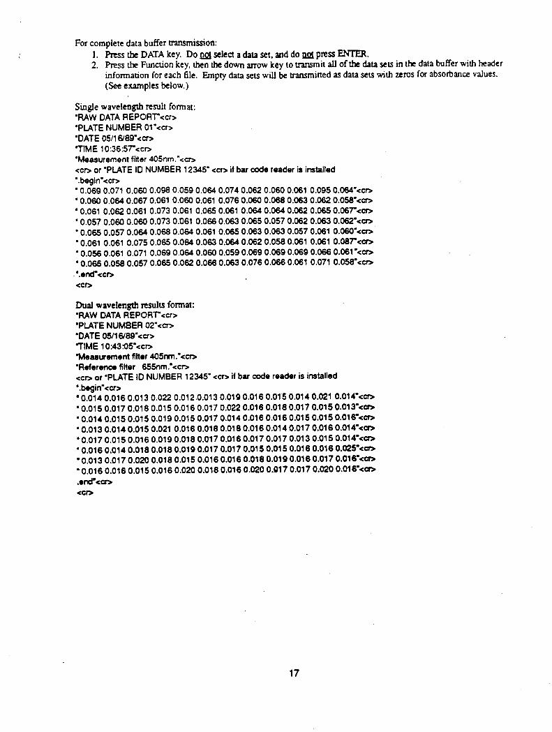
For complete data buffer nansmission: 1. Press the DATA key. Do m selea a data set, and do m ptess WIER. 2. Press the Function key, then the down arrow key to uansmit all of the data sets in the data buffer with header
information for each file. Empty data sets will be transmitted as data sets with zeros for absorbance values. (See examples below.)
Single wavelength result format: 'RAW DATAREPORr<cr> 'PLATE NUMBER Ol’<cr> 'DATE05l16'8Q"ccr> -TIME 10:36:57-<co 'Measurement filter 405nm.'<cr> <coor'PLATEID NUMBER12345"ccr>ifbarcodereaderisinsfalled '.begin'ccr> '0.069 0.071 0.060 0.098 0.059 0.064 0.074 0.062 0.060 0.061 0.0950.064"<cr, '0.060 0.084 0.067 0.061 0.060 0.061 0.076 0.060 0.068 0.063 0.062 O.OW<cr, '0.061 0.062 0.061 0.073 0.061 0.065 0.061 0.064 0.0640.062 0.0650.067"<cr~ '0.057 0.060 0.060 0.073 0.061 0.066 0.063 0.085 0.057 0.062 0.083 0.062'<co '0.065 0.057 0.064 0.0680.064 0.061 0.065 0.063 0.063 0.057 0.061 0.060-<c- '0.061 0.061 0.075 0.065 0.084 0.063 0.0640.062 0.0580.061 0.061 O.o87-<a, '0.056 0.061 0.071 0.069 0.064 0.060 0.0590.0690.069 0.069 0.066 O.o61'<co '0.065 0.0% 0.057 0.065 0.062 0.066 0.063 0.076 0.066 0.061 0.071 0.058.<'*co '.end'ccr, . <CD
Dual wavelength rrsulu format: 'RAWDATAREPORrccr> 'PlATENUMBER02"<m 'DATE 05/16/89"<a> 71ME10:43%I5"<cr> 'Mea?rwementfiRer445nm.'<m 'Reference filter 655nm.'<cr> cc~or~PLATElDNUMBER12345"<cr>ifbarccdereaderisinstalled '.beQin"<cr> '0.014 0.0160.013 0.022 0.012.0.013 0.0190.0160.015 0.0140.021 O.O14"<co '0.015 0.017 0.016 0.015 0.016 0.017 0.022 0.016 0.0180.017 0.0150.013"<cr, '0.014 O.Ol50.015 0.0190.015 0.017 0.0140.016 0.0160.015 0.0150.016"<m '0.0130.0l40.0150.021 0.0160.0180.0180.0180.0140.0170.0160.014-<c- '0.0170.0150.0160.0190.0180.0170.0160.0170.0170.0130.0150.014~<~ '0.0160.014 0.0180.0180.0190.0170.017 0.0150.015 0.0180.0160.025~<a> '0.013 0.0170.020 0.018 0.015 0.0160.0160.0180.0190.0160.0170.016=<a* '0.0160.0160.015 0.0160.020 0.0180.0160.020 0.917 0.0170.020 0.018.<a* .edccrs <cm
17
Sectlon 9 Replacing the Lamp and Installing Interference Nlters
‘Ik Model 3550 Microplate Reader requires very little maintenance. Two important maintenance procedures are chang iog the lamp and iostalling interference filters.
Warning! Eltirical Shock Hamrd! Always unplug the instrument from tbe AC power source before opening the case.
9.1 Changing me L8mp
1. Waning! The lamp may be very bot Use caution and allow tbe lamp to cool before attempting removal, Open the rear case of the instrument by removing tbe four anchor screws; two 00 the back panel and ok each on the sides. Lift off tbe rear cover and locate tbe lamp housing on the left tear kar the cooling fan.
Loosen the two screws that bold the lamp housing cover. Then slide the cover and lift it off.
Release the spring clamp that secutus the lamp.
Carefully pull the lamp assembly away from tbe bezel.
Holding the ceramic base in one band and the lamp housing in the other, carefully pull tbe lamp bee of the base.
6. Carefully insert the new lamp 6rmly in tbe ceramic base. Apply even prcsaum when icuerting the lamp so that the bulb does not become misaligned in tbe reflector housing. Do not to touch the bulb or the inside of the dlector housing during installation.
7. Position the lamp in the bezel so tkt the tab on the lip of the refleaor housing fits in the notch at the 12 o’clock position oo the bezel. Hold the lamp in this positioo until it is secured with tk spring clamp.
8. Replace tbe lamp housing cover and tbe tear compartment cover.
9.2 Installing an InteHerence Filter
1. Open the tear compartment cover as described in Section 9.1, Step 1.
2. Locate the filter wheel and rotate it until tbe titer you wish to remove is in the 12 o’clock pot&too.
3. Tlx filters are held in positioo by small spring clips, and can k removed fmm the wheel without tools. Pinnly grasp the filter housing, being careful not to touch tbe glass elemen, and @I straight up.
4. Insert the new filter with tk spring clip indentations facing the lroa of tbe insmunen. Be sure that the filter is firmly seated.
5. Update tbe filter infonnatiat in tk set system screen. See Section 3.3 for specific instnactioas.
18
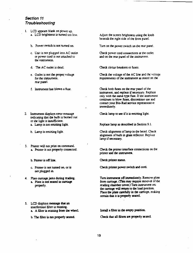
Section 77 Troubleshooting
1. LCD appears blank on wwer up. a LCD brightness is turned too low.
b. Power switch is oot turned on.
c. Unit is mt plugged into AC outlet or power cord is not attached to the instrument
d The AC outlet is dead.
e. Outlet is not the propet voltage for the instniment. rear panel.
f. Instrument has blown a fuse.
.
2. Instnimeot displays error message indicating that the bulb is bumed out or the light is insufficient. a Lamp is 001 emitting light.
b. Lamp is emitting light.
3. Printer will not print 00 command. a. Printer is not properly connected.
b. Prioter is off litr.
c. Printerisnotttxnedon.oris not plugged in.
4. Plate caniage jams dnring reading. a Plateisnotseatedincarriage
PP-JY-
5. LCDdisplaysmessagethatan ioterfermx filter is missing. a A6,lterismissingkomthewheeL
b. ‘Ilx filter is not prqa’ly seated.
Adjust the screen brightness using the knob beneath the right side of the boot panel.
Turn on the power switch on the rear panel.
Check power cord connections at the outlet sod oo the rear panel of the insnument.
Check circuit breakers or fuses.
Check tl~ voltage of the AC line and the voltage nquirements of the insttument as stated on the
check both fuses 00 the rear panel of the instrument, and replace if necessary. Replace only with the same type fuse. If the instrument continues to blow fuses, discontinue use and contact your BieRad service representative immediately.
Check lamp to see ifit is emitting light.
Replace lamp as described in Section 9.1.
Check alignment of lamp in the bezel. Check alignment of bulb in glass reflector. Replnce lamp if necessary.
Ckck th printer interface connections on the printer and tk instntmeot.
ckk priour status.
cbect plitlterpower switch acid cord.
Turn insmrmeti off immediately. Remove plate born carriage. ms may requiie removal of the mdiog chamkr cover.)Tum instrument OK the carriage will return to the lo& position. Place the plate carefuRy in tk carriage. making cextainthatitisproperlyseated.
Iostalla6lteriotkanptypositio4
Check that all filters ate properly seated.
19
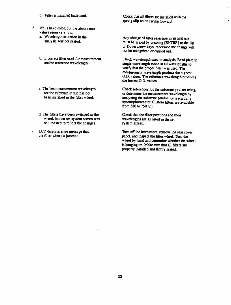
c. Filter is installed backward.
6. Wells have color, but the absorbance values seem very low: a Wavelength selection in the
analysis was oot sealed.
b. Incorrect filter used for measurement and/or reference wavelength.
c. The best measuremeot wavelength for the subsuate in use has oot been installed in tbe filter wheel.
d. The filters have been switched in tbe wheel, but the set system scteeo was not updated to reflect tbe changes.
7. LCD displays error message that tbe tilter wheel is jammed.
check that all filters ate installed with the spring clip notch facing forward.
Any change of filter selection in an aaalysis must be sealed by pressing -1 or the Up or Down arrow keys, otherwise the change will not be recognized or carried out.
Check wavelength used in analysis. Read plate in single wavelength mode at all wavelengths to verify that the proper fQter was used. The measurement waveleogth produce the highest O.D. values. The reference wavelength produces the lowest O.D. values.
Check refereoces for the substrate you are using, or determine the measurement wavelength by analyting the substrate product on a scanning spectropbotometer. Custom titers are available from 380 to 750 MI.
Check tbat the filter positions and their waveleogths are as listed in the set system screeo.
Tbrn off the itsaument, remove tbe rear cover panel, and inspect the 6lter w&l. Tum the wheel by hand and determine whether the wheel is banging up. Make sure that all filters are properly installed and firmly seated.
20
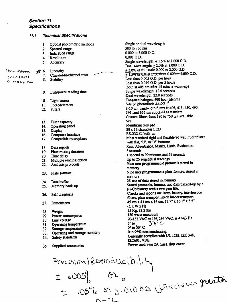
Section 17 Specifhtions
17.1 TechnIca/ SpeCifiCatiOna
1. Optical photometric methods 2. spectral mge 3. indication range 4. Resolution 5. ACZtUXy
‘-hw tqi-em. -;k 6. st\515tmt 7.
0 hxch,nQ- 8.
9.
10. 11. 12.
13. 14. 15. 16. 17.
Filter capacity FaFpml
Computer interface Compatible microplates
18. Data rrporu 19. Plate mixing duration 20. Tie delay 21. Multiple xeading option 22. Analysis protocols
23. Plate formats
24. Data buffa 25. Mmoty back-up
26. Self diagnosis
27. Dimensiotks
28. 29. 30. 31. 32.
G:
weight Powercorrpmnpti- Line vduge ~ll~pm~
35.
LKtz2te--- Stability
Instrument reading time
Lig!l1sou1ce Photodetectors FiltClS
Single or dual wavelength 380 to 750 nm 0.000 to 3.000 O.D. 0.001 O.D. Single wavelength: + 1.5% at 1.000 O.D. Dual wavelength: + 2.0% at 1.000 O.D. + 2.0% of full scale 0.000 to 2.OCQ O.D. + 12. Less than 0.005 O.D. per hour Less thao 0.010 09. per 5 hours (both at 405 nm after 15 minute warm-up) Single wavelength: 12.0 secoods Dual wavelength: 22.0 seconds Tuogsteo halogen, 688 bout lifetime Silicon photodiode LD6c, ? 8-10 nm bandwidth filters h 405,415,450,490, 5%. and 655 nm supplied as standad Custom filters from 380 to 750 nm available. Six Membtane key pad 80 x 16 character LCD RS-232-C. built-in Most standard rigid and flexible 96 well tnicmplates with flat, ‘U’, or ‘V’ butotns Raw, Absorbance, h4auix. Limit, Evaluatioo 3seconds lsecondto99mictutesand59scconds up to 25 sequential teadings Nine wa programmable pmtocds stored in memory Nine usa pfogmnmable plate formats stored in memory 25setsofdatastoIediamemoty smd pmw~~l~, formats, and data backed-up by a Ni-Cd battery witb a two yep life. ckks attd tqorts 00: lamp, battey, interferroce filtas, plate uamport, stack loader anspon 45 cm x 41 an x 14 an, 17.7” x 16.1” x 5.5” (LXWXHI 15 Kg, 33.2 lbs 150 wattstnktlltmt 9@132 VAC or 198-264 VAC at 47-63 Ht so to o”towc
3VL
oto!H4b- Ge#nlly compljesti*8uL 1262, IEC 348, IEC601, VDE power and, two 2A fuses, dust cover
‘3(-a& m\ QJNAAC; bi\i % t OCG tc2, 1
I - J 5, 3’) L57 (J a (y C\Q bb (p&S”~‘pJ-
h--l-
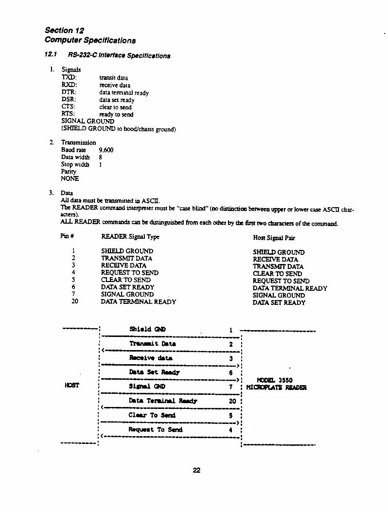
Section 12 Computer Specifications
12.1 M-232-C In terfece Speclfica tlons
1. SigOdS TXD: transit data RXD: receive data DTR: data tetminal ready DSR: data set ready cl-s: clear to send RTS: ready to send SIGNAL GROUND WELD GROUND to hoodkbasis ground)
2. Transmission Baud rate 9,600 Datawidth 8 stop width 1 Parity NONE
3. Data Au data must be transmitted in ASCII. The READER commaud interpreter must be “case blind” (DO distinctjoo between upper or lower case ASCII char- acters). ALL READER commands cao be distioguisbed from each 0th by tbc ti two characters of tbe command.
Pin# READER Signal Type Host Signal Pair
1 SHIELD GROUNJI 2 TRANSMIT DATA 3 RECEIVE DATA 4 REQUESTTO SEND 5 CLEAR TO SEND 6 DATA SET READY 7 SIGNAL GROUND 20 DATA TERMINAL READY
SHIELD GROUND RECEIVE DATA TRANSMIT DATA CLEARTOSEND REQUESTTO SEND DMATERMINAL READY SIGNAL GROUND DATA SET READY
--; shield OID 1 - o---m
: -~.nno---.~;
: Tmnnit bta 2 : :< --one-;
: hive &tr 3 : : --a-- ->: * : masetbecly 6 : :
HOST I --> : lmDa3 3550
siovl- 7 ;--
: r!xQIoRATp RKADea -:
: hta Terriry1 Rewly 20 : :< ---III- : : Clwr To sad 5 : ;--no- ----> : : lbquest To senti--- 4 : : <---O.---o.---- :
---0---0 ; ;-- ---.
22
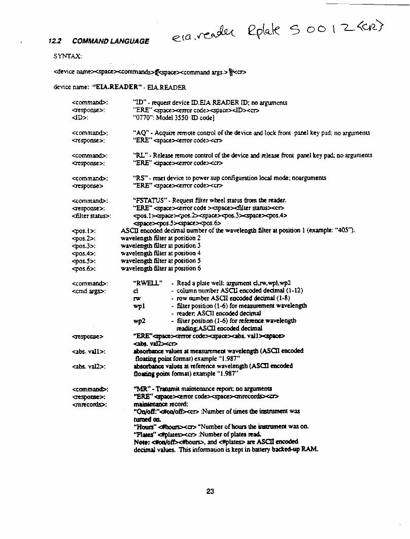
r 12.2 COMMAND LANGUAGE
SYNTAX:
<device namexspace~commands+spacexcommand args.> per,
device name: “EL&READER” - E&READER
<comma&+: “ID” - tequest device LDEIA READER ID; no arguments aespomex “ERE” qacexerror code>qace>dD><cr, dD>: “0770”: Model 3550 ID code)
<command>: uespotse>:
“AQ” - Acquire remote control of the device and lock hont panel key pad; no arguments “ERE” <spacexerror code><-
<command>: aesporw>:
“RL” - Release remote control of tbe &vie and Rlease front panel key p;rd; no arguments “ERE” qncexcrror codexcn
<cornman&: ClCSpOtlSC>
“RS” - reset devia to power sup configuration local mode: noarguments “ERE” cspacexerror code><cm
<cornman&: aesponse>: <filter status>:
90s. 1 >: cpos.2>: cpos.3>: cpos.4>: Cpos.s>: <pos.6>:
“FSTATUS” - Reqyest filter wheel status fram the teader. “ERE” <spacexenor code Xspacctiter status~c~ ~s.l~ace>r~.Zxspace><pos.3xspacexpos.4> ~pace~pos.5~ipace~q~s.6~
ASCII encoded decimal oumber of the wavelength 6lter at position 1 (example: “405’3. wavelength tilter at position 2 wavelength filter at position 3 wavelength filter at position 4 wavelength filter at position 5 wavelength lilter at position 6
<cornmar&: <cmd args~
“RWELL” - Read a plate well: argument cl,rw,wpl,wp2 cl - column number ASCU encoded decimal (1-12) m - row number ASCII encoded decimal (1-8) 91 - filter position (l-6) for measuxun ent wavelength
- rrader. ASCX encoded decimal
CTWpOOSC>
<abs. vail>:
<abs. val2>:
<commatxh CWpOrW>: unlecords:
wp2 - filter petition (I-6) for tefemce wavekogtb rcading;ASCIlenc&ddccimal
“ERE”CpZ-WOf codexspacexabq. vallxsplcu ab6. v- absorbaoce values at measurement wavekngtb (ASCII eacoded floating point format) example “1.987” abswbae values at reference wavelength (ASCII encadcd floatiog pod fanat) example U 1.987”
“MR” - Transmit maintenance report; 00 arguments MERE” cpcexaror codeqacexmrecor mahnance 1ccoTd; “~o~‘*Uon/off~n> :Number of times the imtmmcnt was htmedal. “Hot&* #bouts~n> ‘Number of b the inauumeot was on. “plates” d)platesxa> :Number of plates nad Noto: dodofi5dboun>, aod <#plates illt ASCII encoded decimal values. ‘This information is kept in batty backed-up RAM.
23
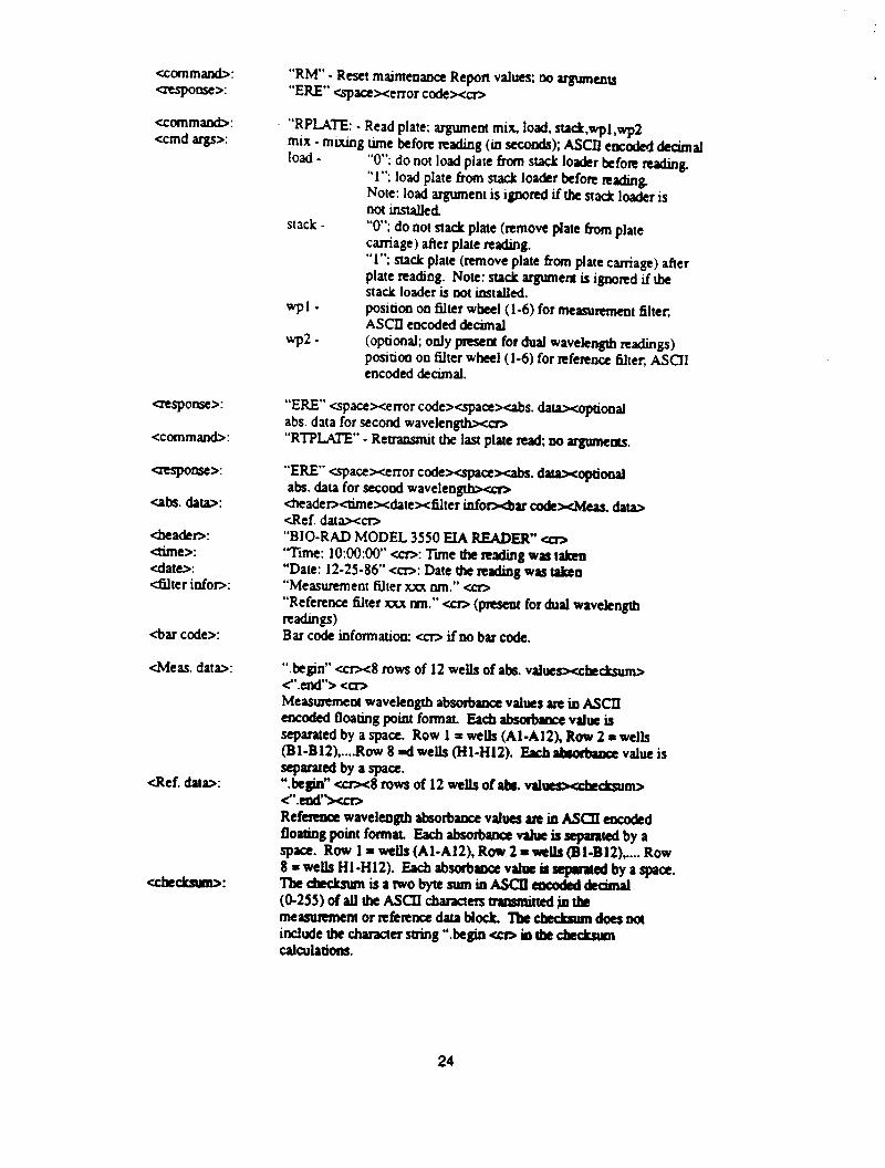
<command>: atspome>:
“RM” - Reset mainteoance Report values; no arguments “ERE” qacexerror codexcn
<cornman&: <cmd argsx
“RFUTE: - Read plate: argument mix, load. stadc.wpl ,wp2 mix - mixing time before rrading (in seconds); ASCII encoded decimal load - “0”; do not load plate fhm stack loader befon mg.
“1”; load plate from stack lo&r kfon reading Note: load argument is ignored if tk stack loader is not installed
stack - “0”; do oot stack plate (remove plate from plate carriage ) after plate reading.
aesponse>:
<command>:
aespoose>:
cabs. data>:
<he&r>: ctime>: <date>: dter inforx
&ar code>:
<Meas. data>:
<Ref. datax
CCkCkSUID:
“1”; stack plate (remove plate hxn plate carriafl) after plate reading. Note: stack argument is ignored if he stack loader is Dot installed. positioo oo filter wheel (l-6) for measurement filter: ASCII encoded decimal (optional; only present for dual wavekngtb readings) positioa oo filter wheel (l-6) for nfercoce 6lter, ASCII encoded decimal.
“ERE” qacexerror codexspacexabs. dataxoptionai abs. data for second wavelengthxch “RTPUTE” - Retransmit the last plate Rad; no argumeas.
“ERE” cspacexerror codexspacexabs. d-optional abs. data for secood waveleo- &adetxhmexdatexblter inforxbar c4xkxMeas. dua> cRef. dataxcm “BIO-RAD MODEL 3550 EIA READER” D ‘Time: 1O:OO:oo” <CD: Tune the reading was taken “Date: 12-25-86” <CD: Date the reading was taken “Measurement filter xxx run.” <CD “Reference filter xxx nm.” <CT, Qxesent for dual wavekngtb =d.@Ss) Bar code information: <CD if no bar code.
“hegin” ccrx8 rows of 12 wells of aba. valwsxckcksum> <“.etxs’> <cm Measurement wavekogtb absohace values are in ASCII ~OdCdfhtiIl~~ifMfO~at &hlbsabyreVdUeiS separated by a space. Row 1 = wells (Al-A12). Row 2 = wells (Bl-BlZ),....Row 8 =d wells (HI-Hl2). Exb abaohux value is separated by a space. “.kgin” an<8 rows of 12 wells of Ibr. vd~cksum> <“.dW Ref- wavelength absorbance values are in ASCIf encoded floating point format. Each absorbance v&e is separated by a spree. Row 1 = wells (Al-A12). Row 2 = wells (Bl-B12) ,.... Row 8 = wells Hl-H12). Each absorb- v&e is mai by a qace. Tbeche&umisatwobytesumioASCll~decimal (O-255) of au tbe ASCII characters trans&W ,jn tk measulementorn!tcnocedataMock. lbeckckaumdoesntn include the character string “he@0 Ccn in lbe &dcSWtI calallations.
24
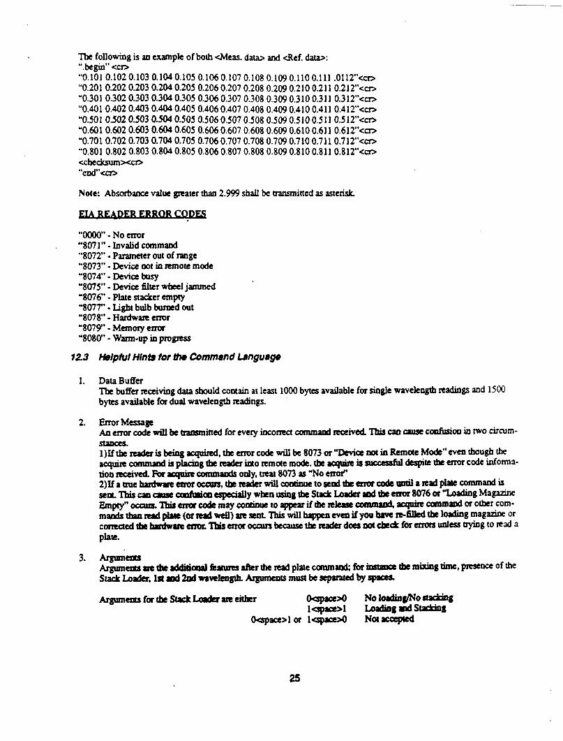
. The fOl]OWhg is an exampk of both &leas. da- and <Ref. data>: “her’ <m “0.101 0.102 0.103 0.1~0.105 0.1060.107 0.108 0.109 0.110 0.111 .0112"<cr> "0.201 0.202 0.203 0.204 0.205 0.2060.207 0.208 0.209 0.210 0.211 0.212"<~17 "0.301 0.302 0.303 0.304 0.305 0.3060.307 0.308 0.309 0.310 0.311 0.312"<cn "0.401 0.402 0.403 0.404 0.405 0.4060.407 0.408 0.409 0.410 0.411 0.412"<cra "0.501 0.502 0.503 0.504 0.505 0.5060.507 0.508 0.509 0.510 0.511 0.512"<cn "0.601 0.602 0.603 0.604 0.605 0.6060.607 0.608 0.609 0.6100.611 0.612"<m "0.701 0.702 0.703 0.704 0.705 0.7060.707 0.708 0.709 0.710 0.711 0.712"<c17 "0.801 0.802 0.803 0.804 0.805 0.8060.807 0.808 0.809 0.8100.811 0.812"<cn <ckcksumxcr> “ed'-
Note: Absorbance value greater than 2.999 shall be tzansmitted as asterisk
“0000” - No error "807 I" - Invalid command “8072” - Parameter out of range "8073" - Device not in ltmou mode "8074"-Deviabusy "8075" - Device titer wheel jammed '8076 - Plate stacker empty ‘8077’ - Light bulb burmd out "80X"-Hardware en-or "8079"-Mtmoryexrur '8080" - warm-up in progIess
12.3 HerprurHInlsfor~CommendLsnguags
1. Data Buffer The buffer receiving data should contain at least 1000 bytes available for single wavekogtb readings and 1500 bytes available for dual wavelength readings. ’
2. ErrorMessage A0 ena code will be hammitted for eve-f-y incomct commaod meived. This can cause c&o0 in two circum- staoes. 1)Xf the rrada is being aquhd, the ermr code will be 8073 or ‘Devil not in Remote Mode” even though the a~cornmlndLplndDgthcrrdu~orrmotemode.thc~issuccessfuldespitsdutmncodeinform3- tioo teceival. For spire canmaoda ooly, ueat 8073 as “No enof 2)Ifa~ehudw~morocc\m,thcMderwillcoatinueto~#ndthearorcodcpDtilarcpdplatecommandis sen.~wausecmfptimespedallywknrtsingtbeSwelLIndtrIrddremrr8076or”LoldiagMa~ Empcy”occun.Tbiremxcodcmay~uetoappuifthcnlersccommrodrquincaamlDd~otbcrcom- mands~rrd~(orndwcll)zrrsent’Ihiswiilhrppnevarifyoohovtn-~thtlodingmaganwor corrraedthchndwrrr~‘IbisenorocavsbecausetbcrraderdoesnMcbcc(LforenonunlesJ~gton;lda plate.
3. Argtlmam Arg\rmcauIrttbcdditiaollk~iffcrtheredplltecanmand;for~tbcmixingtimc,prrscnceofthe StackLoda.Inrrd2odmvrkaglb.AgumeDtsmustbesepMtedbyJp~
ArgumentsfatkStxkLo&razeeitkr izglzf
No loadin~o -8 hld’ilb8mds-8
OGpace>l or lGpace>o Not accepted
25
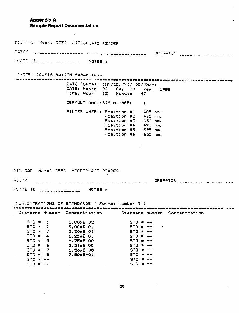
Appendix A Sample Report Documentation
r:,‘..;g#1, .fPdc;l “5,:) ICY.- 111 c.E SF LAT’: F.E$[IEF
a.;;av ._ - se.---...- -- ------------------_-__________ OPEFtATOR --a-- _..- - --._-._--. - ..-
TT’ kL”#Z !3 -.-------------- NOTES :
f'c5TEl-I CCNFIGURATION PbRAMETERS Y= z'==S=IBPlt ttPlllsllxtlrtPtrl=P--- ---DPPI*lllllt3llt=l========-=~========--.------ --------
DCItE FORMAT: cm~/DD/w3/ DD:MM/YY DATE: Month 0 4 Day - (7 Year 3988 TIME: Hour 15 Ml nut;’ 4:
DEFAULT ANALYSIS NUMBER: 1
FILTER WHEEL: F’osition 01 405 n m. Porrtion 82 413 nm. Pori tion *7 433 nm. Position *4 490 nm. Posit a on WS 595 nm. Posi t 1 on #6 655 nm.
2 I ';-RfiD MrJd 0 1 :5:(:l MICROPLATE READER
,: 5 ~: ( : y ---_ ---------------------------------- OPERATOR -------- -. - _ -.. _.- _ __
FL:_I~TE Ii) a---- ----I----- NOTES :
Z'Z'l\rL-ENTRATIONS OF STANDARDS ( Format Number 3 1 =‘“=~~tPDllrfn=fPIIIas~~~~~-~~-~~=*~~~~=~~**~~%==~~~~~~a~¶-~m--~===~=~======~=~=
‘2 t ar,dar d Number Concwttation Standard Number Concwtrat ion
STD# 1 ST3 1) 2 GTD # 7 STD # 4 STD W S STD # 6 STD # 7 STD I) 8 STD 0 -- STD $) --
1 , OOwE 02 s.ocblE 01 2.SOxE 01 1.2SxE 01 6.25xE 00 3.31wE 00 l.ShxE 00 7.80xE-01
STD # -- STD # -- - STD # -- STD (I -- STD # -- STD b -- STD # -- STD b -- STD # -- STD W --
26
assay ..-.-__.--.-----.----- .--..------em .“.__------- --_... _ GFEfiLTOk __~ . ~... ._ _ _ _,. -__ -...a
FLRTE ID --------------- NOTES :
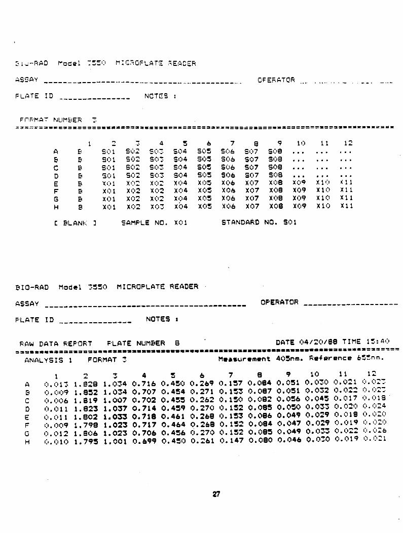
FCRMAT PJlJMtiER 7 ===IT==ltrr===P==D999999==~=~*~=========~----- ----,g===gO==f31=fl====13DPIIPt==’=====a==========
1 2 5 4 s & 7 a 9 10 1 1 12 A G s 0 1 SC12 St:13 so4 SOS SO6 s1:17 so9 . . , . . . . . . E E SO 1 SC12 !j (1’5 so4 SOS SC16 s1:,7 see . , . . , . . . . c EC s 0 1 so2 Cl-la - . .-I so4 SOS SO6 so7 sm . . . . . . . . . D EC GO 1 St:12 si:13 SO4 SC)3 SC16 337 St:18 . , , , , . . . . E B x(:1 1 x02 x 02 x 04 x OS x 06 x 07 x 08 x t:lP x 1 0 x11 F EC x Cl 1 x 02 x 02 x I:) 4 x OS X06 x07 X08 x09 x 1 0 x11 G EC x 0 1 x 132 x I:12 x (:I4 XC)S XC)6 x97 X08 x09 x 10 x11 H P x 0 1 x02 x I:13 xi34 XQS Xi)6 x07 XC@ x09 x 10 x11
C PLANK 3 SAMPLE NO. X01 STFINDARD NO. SO1
BIO-RAD Model 3550 MICROPLATE READER
ASSAY OF'ERCITOR -.-..-.-.-.-.--..--.........--.-...-..-..- ~~~~~~~~~~~~--- --o--
FLATE ID NOTES I --------.------
RAW DATA REPORT F'LATE NUMBER 8 ' DATE 1:)4/2(:)/B6 TIME 1!5:4~:) f1~391193319IaI91399~9~~a~m~~~9~~9a99~99~~9a~g~g9g~a~g~~99~9~999~99999999~~~~~~~
ANALYSIS 1 FORMAT 3 M~rsurement 40Snm. Reference 655nm.
1 2 3 4 s & 7 8 9 10 11 12 C~.O13 1.828 1.034 0.716 0.450 0.r “69 0.157 0.084 O.OSl 0.030 0.021 O.C)X 0.009 1.832 1.034 0.707 0.454 0.271 0.153 t>.t387 Q,Qsl 13.032 Q.1322 I:I.I:I=:
0.006 1.819 1.007 0.702 0.455 0.262 0. 1st) 13.f.182 0.0% 9.045 0.017 Q.(:rl8 (:).011 1.823 1.037 0.714 0.459 0.270 Q.132 0.085 O.QSQ Q.033 Q.Q20 0.024 (:b.(:jll 1.802 I.033 0.718 0.461 0.268 13.153 Q.086 0.049 0.029 0.018 (:),02i.) 0.009 1.798 1.023 0.717 0.464 0.L -68 0. 152 0.084 0. 047 0. 029 0. (:I 19 Cl. QZC) G.012 1.806 1.023 0.706 0.456 rj.270 0.1~ -3 Q.Q~S 0.049 Q.lxz Q. 022 0. Cl26 C,.C)l(:) 1.793 1.001 0.699 0.430 0.i “61 Q. 147 Q.QeQ 0.046 Q.030 0.019 (:).(:l21
27
zI!I-FAD fyods! TTSCl :I I r,F:OF LATE pE;c,~i;
,^,SSQY __---------------------------------------- OFERATOR .__._ -_- - ----- . ..--- ._-_ -
FLATE ID --------e---e-- NOTES :
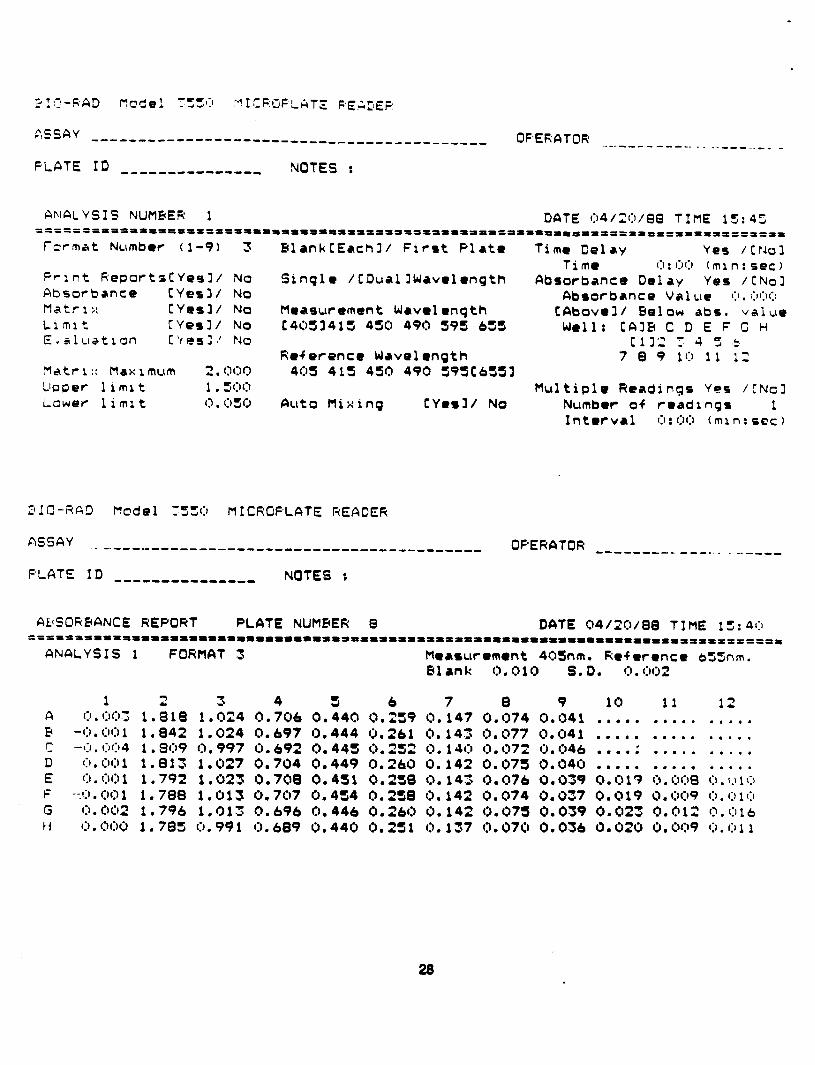
ANALYSIS NUMBER 1 DATE 04/20/813 TIME 15:45 =======~aaaa~~a~a~aapp111111111p11111131a~aa~aa~a Paa1aaaaaaa=aaaaaaaaa~a~~aa~a~~
format Number (l-9) 3 ElanklEachl/ First Plate Time Delay Yes /trJol Time 0 : 00 ( m 1 n : see )
Print ReportoCYesl/ No Single /CDual IWavelength Absorbance Delay Yes /CNol Absorbance [Yes31 No Absorbance Val ue 0. ~:O:r Matrl;: CYesl/ No Measurement Wave1 l ngth CAbovell Below abs. value Ll ml t [YesI/ No c4053415 450 490 595 653 Well: CR35 C D E F C H E.slustron c‘fssl~ No Cl12 1: 4 5 .5
Reference Wave1 l ngth 7 8 9 10 11 12 Matr i :: Max 1 InLlln z l I300 40s 415 450 490 595C63Sl Upper 1 i ml t 1 . 5t:,1:, Multiple Readings Yes /CNcl Lower 1 i ml t I:, . lj5Q Fluto Mixing CYesl/ No Number of readings 1
Interval (11 : OCI ( mi n : SFC 1
31fl-RAD f-lode1 :X(:J MICROPLATE READER
ASSAY ._---I----------------------------------- OPERATOR B---M---- e-w. . - -..----
F’LATE ID --------------- NOTES :
WSORBANCE REPORT PLATE NUMBER 8 DATE 04/X)/88 TIME 15:40 9=aaIPIaaaIaIaIaaaIaaaaaaaamaaaaa¶~aaaaa~aaaaaaaaaaaaa~as~aaaaaaaa~aaaaaaaaa===a
ANALYSIS 1 FORMAT 3 Measurement 40’Jnm. Reference 655nm. Pl l nk 0.010 S.D. 1:) . (j(j 2
1 2 A 0. 003 1 . a 18 5 -0. 00 1 1 , 842 r -I:,. (:)(:,4 1 . 3Q9 D 0, cm 1 1 . 8 13 E Cl. CrO 1 1 . 792 F --.'I) . 00 1 1 . 788 G 0. 002 1 . 796 14 0. OCKJ 1 . 785
3 4 3 6 7 8 9 10 11 12 1.024 0.706 0.440 0.23 9 0.147 0.074 0.041 . . . . . .*... .,... 1.024 0.697 0.444 0.161 0.143 0.077 0.041 . . . . . . . . . . . . . . . 0.997 0.692 (3.443 0 .252 0.140 0.1372 0.046 . . . . . - .,... .,.., 1.027 0.744 0.449 0.260 0.142 0.075 0.040 . . . . . . . . . . . . . . . 1.023 0.709 0.451 0.258 0. 143 0.076 0.039 0.013 0.008 0.~10 1.013 0.707 0.454 0 .258 0.142 0.074 0.037 0.019 0.cm9 C~.OlO 1.013 (3.696 0.446 0.260 0.14 2 0.075 0.039 0.023 0.012 0.016 0.991 0.689 0.440 0.231 0. 137 0.070 0.036 Q.OZO 0.009 0.01 1
28
& II-KAD Mode 1 :szd MICROF,LATE REALER
ASSAY ______----------------------- ..------------- OFERATOR ---------_-- . -_---.--,
PLATE ID --e---.m--------m NOTES :
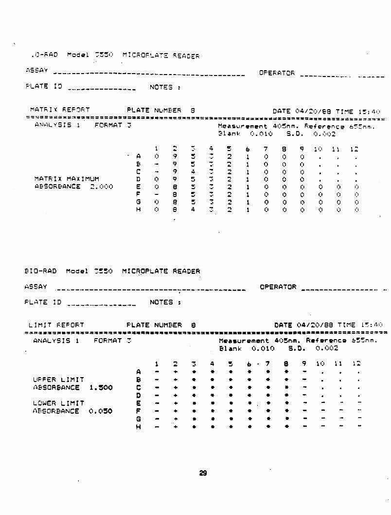
MATR I X F:EFOF;T PLATE NLjMBER 9 DATE O4/3)/99 TIME 15. z=-Jsa 9=0=53af=aaaaaaaIaaaaaaa=~==aa=a=~a=a~~aa~ a~aaaaaPaaa==a=a;-----~----.-~~‘~- -B--s --w-e----..
AhlcLYsIS 1 FORMAT 3 Measurement 403nm. Reference 655nm. 21 an):: 0 . c, 10 S.D. (‘.I . \:I( j 2
1 2 ? 4 5 6 7 6 9 10 11 12 - A I:) v 5 J 2 1 t:, I:, 1:) . , .
5 - v 5 3 2 1 0 I:) Cl . . . c - 9 4 3 2 1 1:) (:I (:I . , .
MATRIX MAXIMUM 0 Cl cl AESOREANCE 2 . (:ll:ll:I
H I:) 8 4 3 2 1 (:I f:t I:, 1:) (:I (:I .
PIO-RAD Model 7530 MICf3PPLATE READER
ASSAY .---.--.-------------------------..----.------- OPERATOR ------------------ -- r
PLATE ID _____...__-_-w-m - NOTES :
LIMIT REPORT FLATE NUMPER 8 DATE 04/3:1/@8 TIME 17: 40 ==a fsaaaaaaaazaaaaaaaaaaaaaaaaaaaaa aa~~aaaaaaapaaaaaa~aaaaaaaaaaaaaaaaaaa~~~~~~
ANALYSIS 1 FORMAT 5 Measurement 4OSnm. kef erence . Blank 0.010 S. 0. 0, ~:lf:i2
1 2 ‘5 4 3 6-7 0 9 10 1 1 A - + + * l I) l l - . .
Ut=PER LIMIT B - + Ic l it, l 1) I) - . .
ABSORBANCE 1.500 C-+*++***-., D - + IC * I) l + w 0..
LOWER LIMIT E - + 0 * l +,* l - - -
fltiSOkEU3NCE Ct. 0% F - + + w l + w l - - -
0 - ,,z 0 l 46 + l 0 - - -
H - 4b 0 + + l l 0 - -
bS5nm.
12 . . . .
29
:I L3-FfAC hcde 1 :YYQ MI CKPLATE REA@EP
ASSAY -.-^--_------------- ------e-w ---_ .__ .__----- - WERATOFi .--w-e- --._ ^ _. _.. _-
FLATE ID ----a---------- NOTES :
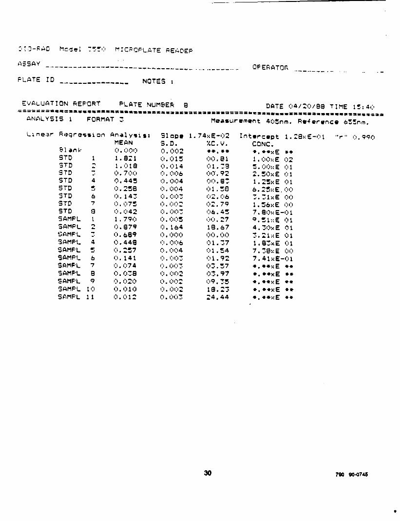
EVALUATION REPORT PLATE NUMB& 8 DCITE 1:14/3:)/88 TIME 15: 41:) ~%~PfP~t%P%l%%3%%a%lIIIIIPIIIPIppIPIIIPt%¶%¶aa%=%=~- ~%1%%PII%%ll%ol%lllP~%%~%*%~%
ANALYSIS 1 FORMAT 3 Measurement 405nm. Reference 655nm.
La near Reqrossi on
Pl ank STD 1 9TD STD ; STD 4 STD 5 STD STD 7” STD 8 SAMPL 1 SAMF’L 2 Sf\MFL 7 SaMPL 4 SCSMF’L ‘J SAMFI, 6 SfirlPL f SAMF’L B SAMF’L 9 SIQMPL 10 SAMPL 11
Analyoisr MEAN (:I, (:ll:,f:) 1.821 1 . 0 1 8
0. 7I:ll:J 0.445 0. 238 (:I. 143 1:). 1375 I:) . I:142 1 . 790 0 . 8 7 9 0. 689 0, 448 (.I . 2s 7 1:) . 1 4 1 Cl. 074 (3. CJX 1-1 (‘1 ?I? . . .&. (:I . I:, 1 (3 0 . I:, 1 2
Sl ape 1 .74xE-02 S.D. xc. v. 0 . (:I I:, 2 l )+, I)+ Cl . 1:1 1 5 CJC). 81 0 , CJ 1 4 0 1 .73 (:I . l:ll,56 OQ. 92 0. 004 or:). 87 0 . tJo4 0 1 . se (‘I . . (‘I (‘I - . . 2 02, 06 c:r . I:1 I:, 2 02. 79 (‘I . . WI - -8 . _ Cl6. 43 (‘I 1:): (‘ll’l~ * 164 _ (,I:, 27 10.67 ,
0 . (:l(:lI:, g1:1 . c:li,l
(:I . c:,Q6 0 1 .57 (:I . C,C\4 0 1 , 34 l-l l’)I’lT . . . . s’ 1:) 1 l 92 I:, . l:ll:,y OZ.57 c:r , t:N:l2 (33.97 1:). l):l= 1-19 TT l S’b
1:) . 01:) 2 ia. 0, I:)(:,3 24.44
Intercept 1,28xE-Cl1 "r " I:I , 990 CONC. l ,+*xE l +
1 , Ot.1;; E 02
5 . (:I(:,;: E (:I 1
2. 3&E r:11
1 .25xE 01 6 .2ir;>: E , t:,c:r
- :;lxE Or:) 2 .
1 . 542: E (:,(:I
7. 80x E-0 1 9. 51::E 01 4.3OwE 01 3 . 2 1 x E 0 1 1.8ZwE 01 7 . :a;:E I:H:I
7.41xE-01 l ,*axE ++ l .**xE .* *,.++xE l w
+.w,,;E *)I)
+.cr+s:E ee .
30 790 00474s