Model 3000TA Quickstart - teledyne-ai.com · Model 3000TA Quickstart Guide Teledyne Analytical...
19
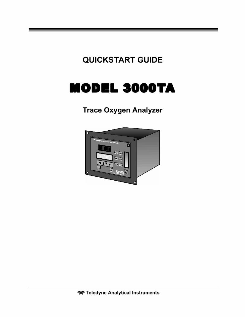
Teledyne Analytical Instruments QUICKSTART GUIDE MODEL 3000TA Trace Oxygen Analyzer
-
Upload
truongngoc -
Category
Documents
-
view
237 -
download
0
Transcript of Model 3000TA Quickstart - teledyne-ai.com · Model 3000TA Quickstart Guide Teledyne Analytical...
Teledyne Analytical Instruments
QUICKSTART GUIDE
MODEL 3000TA
Trace Oxygen Analyzer
Quickstart Guide Trace Oxygen Analyzer
Teledyne Analytical Instruments
Model 3000TA Quickstart Guide
Teledyne Analytical Instruments 3
GETTING STARTED
This Quickstart Guide is designed to get you set up and operating your Teledyne Analytical Instruments Analyzer quickly. It shortcuts the details so you can install and use your new analyzer with a minimum of fuss. This Quickstart Guide should be used in conjunction with the Instruction Manual that shipped with your instrument. Only necessary features to get you operational are discussed in this guide. Many of the advanced features of this analyzer are not described here so you should refer to the Instruction Manual to get the most from your analyzer
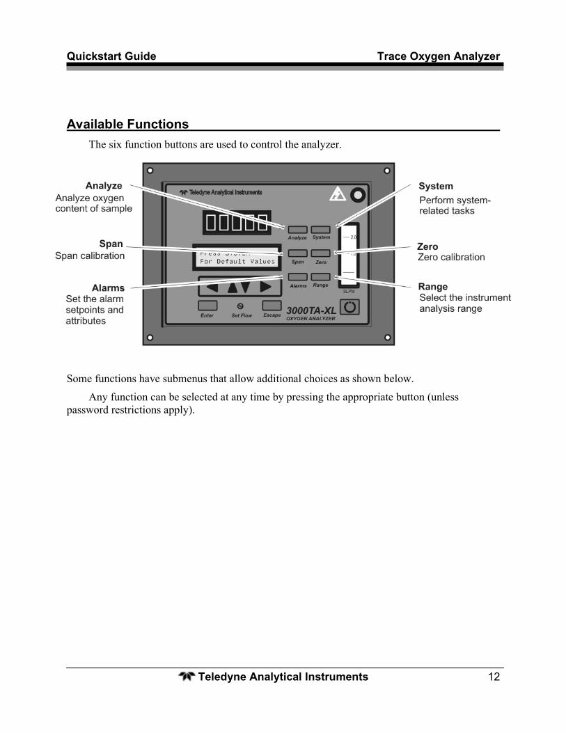
Front Panel (Operator Interface)
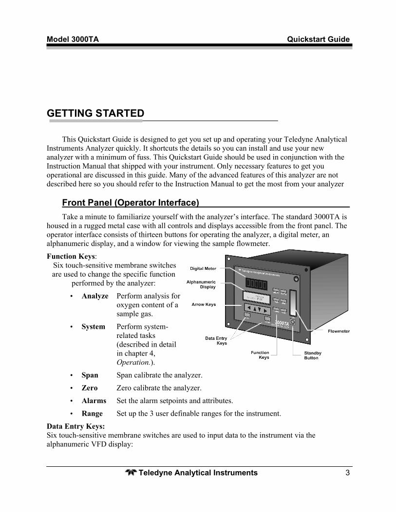
Take a minute to familiarize yourself with the analyzer’s interface. The standard 3000TA is housed in a rugged metal case with all controls and displays accessible from the front panel. The operator interface consists of thirteen buttons for operating the analyzer, a digital meter, an alphanumeric display, and a window for viewing the sample flowmeter.
Function Keys: Six touch-sensitive membrane switches are used to change the specific function
performed by the analyzer:
• Analyze Perform analysis for oxygen content of a sample gas.
• System Perform system-related tasks (described in detail in chapter 4, Operation.).
• Span Span calibrate the analyzer.
• Zero Zero calibrate the analyzer.
• Alarms Set the alarm setpoints and attributes.
• Range Set up the 3 user definable ranges for the instrument.
Data Entry Keys: Six touch-sensitive membrane switches are used to input data to the instrument via the alphanumeric VFD display:
Quickstart Guide Trace Oxygen Analyzer
Teledyne Analytical Instruments 4
• Left & Right Arrows Select between functions currently displayed on the VFD screen.
• Up & Down Arrows Increment or decrement values of functions currently displayed.
• Enter Advances VFD display to the next screen in a series or returns to the Analyze screen if none remain.
• Escape Backs VFD display to the previous screen in a series or returns to the Analyze screen if none remain.
Digital Meter Display: The meter display is a Light Emitting Diode (LED) device that produces large, bright, 7-segment numbers that are legible in any lighting. It produces a continuous readout from 0-10,000 ppm and then switches to a continuous percent readout from 1-25%.
Alphanumeric Interface Screen The VFD screen displays values, options, and messages for immediate feedback.
Set Flow: Needle valve used to adjust flow of gas sample
Flowmeter: Monitors the flow of gas past the sensor. Readout is 0.2 to 2.4 SLPM of nitrogen.
Standby Button: The Standby turns off the display and outputs, but circuitry is still operating.
Access Door: For access to the Micro-fuel Cell,the front panel swings open when the latch in the upper right corner of the panel is pressed all the way in.
Rear Panel (Equipment Interface)
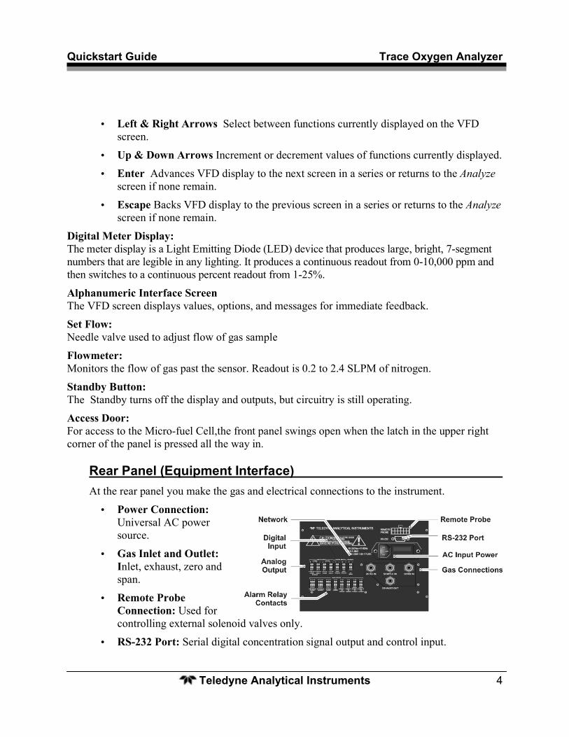
At the rear panel you make the gas and electrical connections to the instrument.
• Power Connection: Universal AC power source.
• Gas Inlet and Outlet: Inlet, exhaust, zero and span.
• Remote Probe Connection: Used for controlling external solenoid valves only.
• RS-232 Port: Serial digital concentration signal output and control input.
Model 3000TA Quickstart Guide
Teledyne Analytical Instruments 5
• Analog Output Connection: Terminals for current and voltage analog output signals.
• Digital Input Terminals: Terminals for connecting digital input signals.
• Alarm Connections: 2 concentration alarms and 1 system alarm.
• Calibration Contact : To notify external equipment that instrument is being calibrated and readings are not monitoring sample.
• Range ID Contacts: Four separate, dedicated, range relay contacts. Low, Medium, High, Cal.
• Remote Span/Zero: Digital inputs for externally controlling calibration.
• Network I/O: Serial digital communications for local network access.
Quickstart Guide Trace Oxygen Analyzer
Teledyne Analytical Instruments 6
SETUP AND INSTALL
Mount the Analyzer
The Model 3000TA is for indoor use in a general purpose area. It is NOT for hazardous environments of any type. It is designed for flush panel mounting. Use the four mounting holes—one in each corner of the rigid frame to panel mount the instrument.
Gas Connections
Note: Do not remove plastic caps on VCR fittings, unless you are ready to make connections.
The analyzer is equipped with 1/4 inch tube fittings, and 6 mm adapters are supplied for metric system installations.
You will need:
• Zero gas — regulated supply of oxygen free gas.
• Span gas — regulated supply of a standard gas typically containing oxygen at 70-90% of the full scale value on the range of interest.
• Purge gas — oxygen free inert gas for purging if applicable.
• Sample gas — regulated supply of sample gas available to the analyzer.
Make your gas connections to the analyzer as follows:
1. Install the flow restrictor that shipped with your instrument:
• For positive pressure applications, install the restrictor with the blue dot to the SAMPLE IN port. The small circular orifice should face away from the back of the unit. Remove the sticker after installing.
• For low pressure applications (less than 5 psig), connect the restrictor without the blue dot to the SAMPLE IN port.
• For vacuum service (5-10 in Hg), install the restrictor without the blue dot to the EXHAUST port.
2. Connect your sample gas to the SAMPLE IN port.
3. Connect a vent line to EXHAUST OUT port.
Model 3000TA Quickstart Guide
Teledyne Analytical Instruments 7
4. If using remote calibration feature:
• Connect zero gas to the ZERO IN port.
• Connect span gas to the SPAN IN port.
5. Otherwise, calibration gases must be Tee'd into the sample inlet with appropriate valves.
6. Regulate the sample gas pressure between 2 and 50 psig sufficient to keep the front panel flowmeter reading in an acceptable range (0.1 to 2.4 SLPM). For non-pressurized sample or very low pressure, (less than 2 psig) vacuum service plumbing is recommended.
7. If greater sample flow is required for improved response time, install a bypass in the sampling system upstream of the analyzer input.
8. For optional vacuum application where the sample pressure is at atmospheric or very low pressure, the instrument should be fitted with the vacuum service option. This option locates the flow control valve on the exhaust side of the Micro-fuel Cell.
Note: Exhaust connections must be consistent with the hazard level of the constituent gases. Check Local, State, and Federal laws, and ensure that the exhaust stream vents to an appropriately controlled area, if required.
Electrical Connections
CAUTION: READ ALL SAFETY INFORMATION REGARDING ELECTRICAL HAZARDS ASSOCIATIED WITH THIS INSTRUMENT BEFORE MAKING ELECTRICAL CONNECTIONS.
CAUTION: POWER IS APPLIED TO THE INSTRUMENT'S CIRCUITRY AS LONG AS THE INSTRUMENT IS CONNECTED TO THE POWER SOURCE. THE RED SWITCH ON THE FRONT PANEL IS FOR SWITCHING POWER ON OR OFF TO THE DISPLAYS AND OUTPUTS ONLY.
Quickstart Guide Trace Oxygen Analyzer
Teledyne Analytical Instruments 8
• Connect primary input power: Insert the power cord into the power cord receptacle.
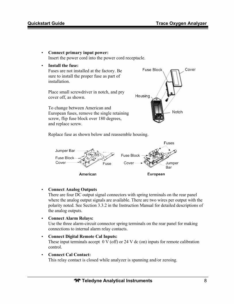
• Install the fuse: Fuses are not installed at the factory. Be sure to install the proper fuse as part of installation. Place small screwdriver in notch, and pry cover off, as shown. To change between American and European fuses, remove the single retaining screw, flip fuse block over 180 degrees, and replace screw. Replace fuse as shown below and reassemble housing.
• Connect Analog Outputs There are four DC output signal connectors with spring terminals on the rear panel where the analog output signals are available. There are two wires per output with the polarity noted. See Section 3.3.2 in the Instruction Manual for detailed descriptions of the analog outputs.
• Connect Alarm Relays: Use the three alarm-circuit connector spring terminals on the rear panel for making connections to internal alarm relay contacts.
• Connect Digital Remote Cal Inputs: These input terminals accept 0 V (off) or 24 V dc (on) inputs for remote calibration control.
• Connect Cal Contact: This relay contact is closed while analyzer is spanning and/or zeroing.
Model 3000TA Quickstart Guide
Teledyne Analytical Instruments 9
• Connect Range ID Contacts: There are four dedicated Range ID relay contacts on the rear panel. The first three ranges are assigned to relays in ascending order. Range 1 ID— Low range Range 2 ID— Medium range Range 3 ID— High range Range 4 ID—Air Cal Range (25%).
• Network I/O: A serial digital input/output for local network protocol. At this printing, this port is not yet functional. It is to be used in future options to the instrument.
• Connect the 9-pin D connector to the RS-232 serial port. See Section 3.3.2 in the Instruction Manual for information on setting up serial communication for this instrument.
Install the Micro-fuel Cell The Model 3000TA is designed to accept the L2C Micro-fuel Cell or as an option, it can use
the B2 series of Micro-fuel Cells by incorporating a spacer adaptor (Teledyne P/N B66378).
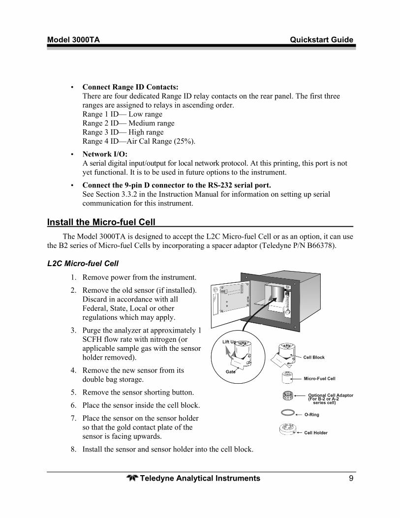
L2C Micro-fuel Cell
1. Remove power from the instrument.
2. Remove the old sensor (if installed). Discard in accordance with all Federal, State, Local or other regulations which may apply.
3. Purge the analyzer at approximately 1 SCFH flow rate with nitrogen (or applicable sample gas with the sensor holder removed).
4. Remove the new sensor from its double bag storage.
5. Remove the sensor shorting button.
6. Place the sensor inside the cell block.
7. Place the sensor on the sensor holder so that the gold contact plate of the sensor is facing upwards.
8. Install the sensor and sensor holder into the cell block.
Quickstart Guide Trace Oxygen Analyzer
Teledyne Analytical Instruments 10
9. With the O-ring in place, align the guide pin with the hole on the cell holder. Then, with the holder, lift cell into the cell block.
10. Push the gate on the cell block down so that the slots on the side of the gate engage the locating screws on the side of the block. This forces the holder into position and forms a gas-tight seal.
11. Purge the system using sample or zero gas.
12. Power the system back up.
If the installation is carried out quickly enough, the sensor will reach a stable low value less than 1 ppm in approximately 8 hours or less.

Model 3000TA Quickstart Guide
Teledyne Analytical Instruments 11
BASIC OPERATION
Once the analyzer has been installed, it can be configured for your application. Prior to using the instrument you must:
• Calibrate the instrument
• Define the analysis ranges and choose whether to use autoranging or a fixed range.
• Set alarm setpoints and modes of alarm operation.
Additional configuration parameters are available to tailor the instrument to your particular application. Refer to the Instruction Manual for specific information on setting of additional system parameters.
Default Configuration The default analyzer configuration is as follows:
Ranges: LO = 100 ppm, MED = 1000 ppm, HI = 10,000 ppm.
Auto Ranging: ON
Alarm Relays: Defeated, 1000 ppm, HI, Not failsafe, Not latching.
Zero: Auto, every 0 days at 0 hours.
Span: Auto, at 000,008.00 ppm, every 0 days at 0 hours.
If you choose not to use password protection, the default password is automatically displayed on the password screen when you start up, and you simply press Enter for access to all functions of the analyzer.
Using the Data Entry and Function Buttons The ◄► arrow buttons select options from the menu currently being displayed on the
display. When selected, the option blinks.
When the selected option includes a modifiable item, the ▲▼ arrow buttons can be used to increment or decrement that modifiable item.
The Enter button is used to accept any new entries on the VFD screen.
The Escape button is used to abort any new entries on the VFD screen that are not yet accepted by use of the Enter button.
Quickstart Guide Trace Oxygen Analyzer
Teledyne Analytical Instruments 12
Available Functions The six function buttons are used to control the analyzer.
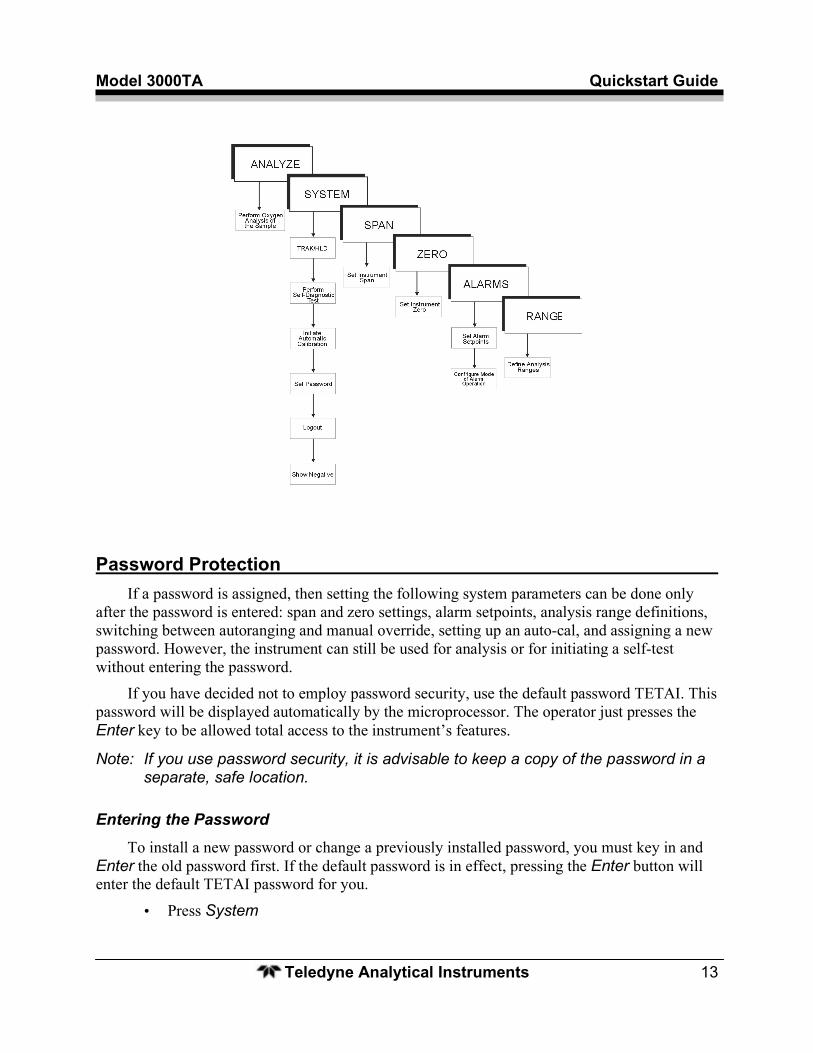
Some functions have submenus that allow additional choices as shown below.
Any function can be selected at any time by pressing the appropriate button (unless password restrictions apply).
Model 3000TA Quickstart Guide
Teledyne Analytical Instruments 13
Password Protection
If a password is assigned, then setting the following system parameters can be done only after the password is entered: span and zero settings, alarm setpoints, analysis range definitions, switching between autoranging and manual override, setting up an auto-cal, and assigning a new password. However, the instrument can still be used for analysis or for initiating a self-test without entering the password.
If you have decided not to employ password security, use the default password TETAI. This password will be displayed automatically by the microprocessor. The operator just presses the Enter key to be allowed total access to the instrument’s features.
Note: If you use password security, it is advisable to keep a copy of the password in a separate, safe location.
Entering the Password
To install a new password or change a previously installed password, you must key in and Enter the old password first. If the default password is in effect, pressing the Enter button will enter the default TETAI password for you.
• Press System
Quickstart Guide Trace Oxygen Analyzer
Teledyne Analytical Instruments 14
TRAK/HLD Auto—Cal PSWD Logout More
• Use the ◄► arrow keys to scroll the blinking over to PSWD,
• Press Enter to select the password function. Either the default TETAI password or AAAAA place holders for an existing password will appear on screen depending on whether or not a password has been previously installed.
T E T A I Enter PWD
—or— A A A A A Enter PWD
• If you are not using password protection, press Enter to accept TETAI as the default password. If a password has been previously installed, enter the password using the ◄► arrow keys to scroll back and forth between letters, and the ▲▼ arrow keys to change the letters to the proper password.
• Press Enter to enter the password. Change Password? <ENT>=Yes <ESC>=No
• Press Escape.
Calibration of the Analyzer The analyzer is calibrated using zero and span gases. This Quickstart Guide describes both
manual and auto mode calibration. You can s switch between the two any time using the procedures described below.
Any suitable oxygen-free gas can be used for zero gas as long as it is known to be oxygen free and does not react adversely with the sample system. For span gas, use a known gas containing oxygen in the range of 70-90% of full scale on the range of interest.
Zero Calibration
Make sure an appropriate zero gas is connected to the sample port. Adjust the gas pressure until the flowrate as indicated on the front panel flowmeter settles between 0.1 and 2.4 SLPM (0.2 –5 SCFH).
Model 3000TA Quickstart Guide
Teledyne Analytical Instruments 15
Auto Mode Zero Calibration
• Press Zero to enter the zero function mode. • Use the ▲▼ arrow keys to toggle between AUTO and MAN zero settling. Stop when
AUTO appears blinking. Zero: Settling: AUTO <ENT> To Begin
• Press Enter to begin zeroing. #### PPM Zero Slope=#### ppm/s
.
.
.
#### PPM Zero 4 Left=### ppm/s
The zeroing process will automatically conclude when the output is within the acceptable range for a good zero. Then the analyzer automatically returns to the Analyze mode.
Manual Mode Zeroing
• Press Zero to enter the Zero function. • Use the ▲▼ keys to toggle between AUTO and MAN zero settling. Stop when MAN
appears, blinking, on the display. Zero: Settling: Man <ENT> To Begin
• Press Enter to begin the zero calibration. #### ppm Zero Slope=#### ppm/s
Once zero settling is completed, the instrument automatically returns to the Analyze mode.
Quickstart Guide Trace Oxygen Analyzer
Teledyne Analytical Instruments 16
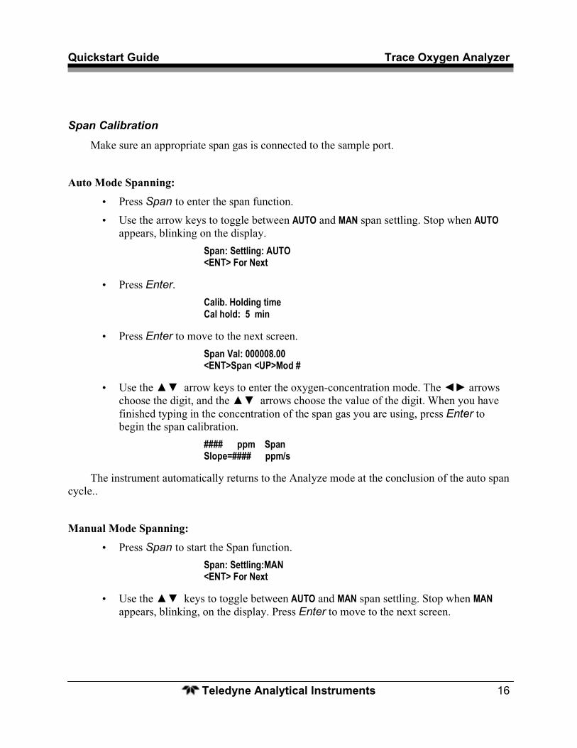
Span Calibration
Make sure an appropriate span gas is connected to the sample port.
Auto Mode Spanning:
• Press Span to enter the span function. • Use the arrow keys to toggle between AUTO and MAN span settling. Stop when AUTO
appears, blinking on the display. Span: Settling: AUTO <ENT> For Next
• Press Enter. Calib. Holding time Cal hold: 5 min
• Press Enter to move to the next screen. Span Val: 000008.00 <ENT>Span <UP>Mod #
• Use the ▲▼ arrow keys to enter the oxygen-concentration mode. The ◄► arrows choose the digit, and the ▲▼ arrows choose the value of the digit. When you have finished typing in the concentration of the span gas you are using, press Enter to begin the span calibration.
#### ppm Span Slope=#### ppm/s
The instrument automatically returns to the Analyze mode at the conclusion of the auto span cycle..
Manual Mode Spanning:
• Press Span to start the Span function. Span: Settling:MAN <ENT> For Next
• Use the ▲▼ keys to toggle between AUTO and MAN span settling. Stop when MAN appears, blinking, on the display. Press Enter to move to the next screen.
Model 3000TA Quickstart Guide
Teledyne Analytical Instruments 17
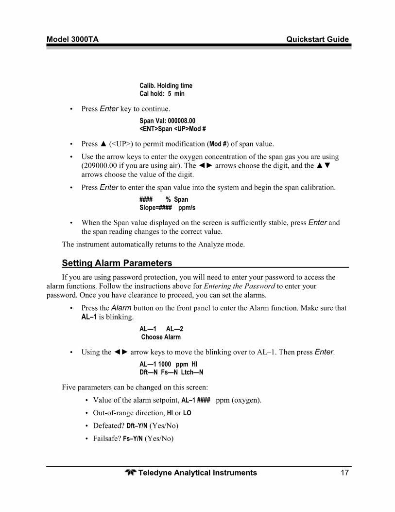
Calib. Holding time Cal hold: 5 min
• Press Enter key to continue. Span Val: 000008.00 <ENT>Span <UP>Mod #
• Press ▲ (<UP>) to permit modification (Mod #) of span value.
• Use the arrow keys to enter the oxygen concentration of the span gas you are using (209000.00 if you are using air). The ◄► arrows choose the digit, and the ▲▼ arrows choose the value of the digit.
• Press Enter to enter the span value into the system and begin the span calibration. #### % Span Slope=#### ppm/s
• When the Span value displayed on the screen is sufficiently stable, press Enter and the span reading changes to the correct value.
The instrument automatically returns to the Analyze mode.
Setting Alarm Parameters If you are using password protection, you will need to enter your password to access the
alarm functions. Follow the instructions above for Entering the Password to enter your password. Once you have clearance to proceed, you can set the alarms.
• Press the Alarm button on the front panel to enter the Alarm function. Make sure that AL–1 is blinking.
AL—1 AL—2 Choose Alarm
• Using the ◄► arrow keys to move the blinking over to AL–1. Then press Enter. AL—1 1000 ppm HI Dft—N Fs—N Ltch—N
Five parameters can be changed on this screen:
• Value of the alarm setpoint, AL–1 #### ppm (oxygen).
• Out-of-range direction, HI or LO
• Defeated? Dft–Y/N (Yes/No)
• Failsafe? Fs–Y/N (Yes/No)
Quickstart Guide Trace Oxygen Analyzer
Teledyne Analytical Instruments 18
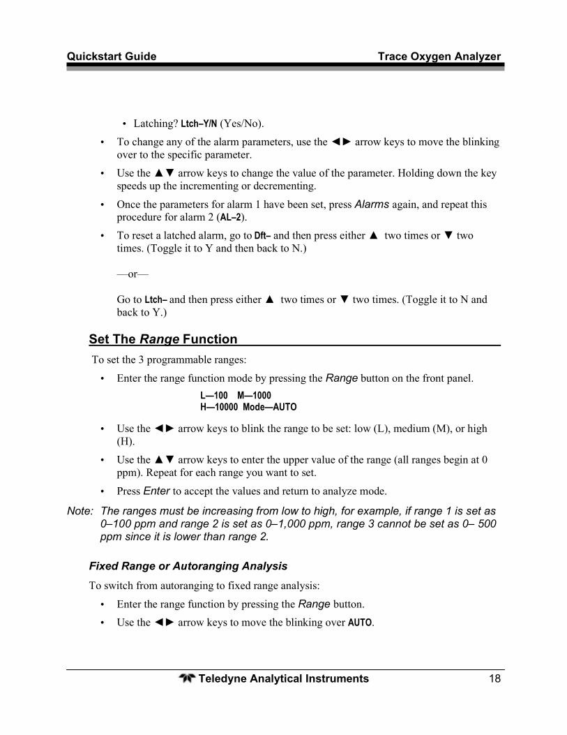
• Latching? Ltch–Y/N (Yes/No).
• To change any of the alarm parameters, use the ◄► arrow keys to move the blinking over to the specific parameter.
• Use the ▲▼ arrow keys to change the value of the parameter. Holding down the key speeds up the incrementing or decrementing.
• Once the parameters for alarm 1 have been set, press Alarms again, and repeat this procedure for alarm 2 (AL–2).
• To reset a latched alarm, go to Dft– and then press either ▲ two times or ▼ two times. (Toggle it to Y and then back to N.) —or— Go to Ltch– and then press either ▲ two times or ▼ two times. (Toggle it to N and back to Y.)
Set The Range Function To set the 3 programmable ranges:
• Enter the range function mode by pressing the Range button on the front panel. L—100 M—1000 H—10000 Mode—AUTO
• Use the ◄► arrow keys to blink the range to be set: low (L), medium (M), or high (H).
• Use the ▲▼ arrow keys to enter the upper value of the range (all ranges begin at 0 ppm). Repeat for each range you want to set.
• Press Enter to accept the values and return to analyze mode.
Note: The ranges must be increasing from low to high, for example, if range 1 is set as 0–100 ppm and range 2 is set as 0–1,000 ppm, range 3 cannot be set as 0– 500 ppm since it is lower than range 2.
Fixed Range or Autoranging Analysis
To switch from autoranging to fixed range analysis:
• Enter the range function by pressing the Range button. • Use the ◄► arrow keys to move the blinking over AUTO.
Model 3000TA Quickstart Guide
Teledyne Analytical Instruments 19
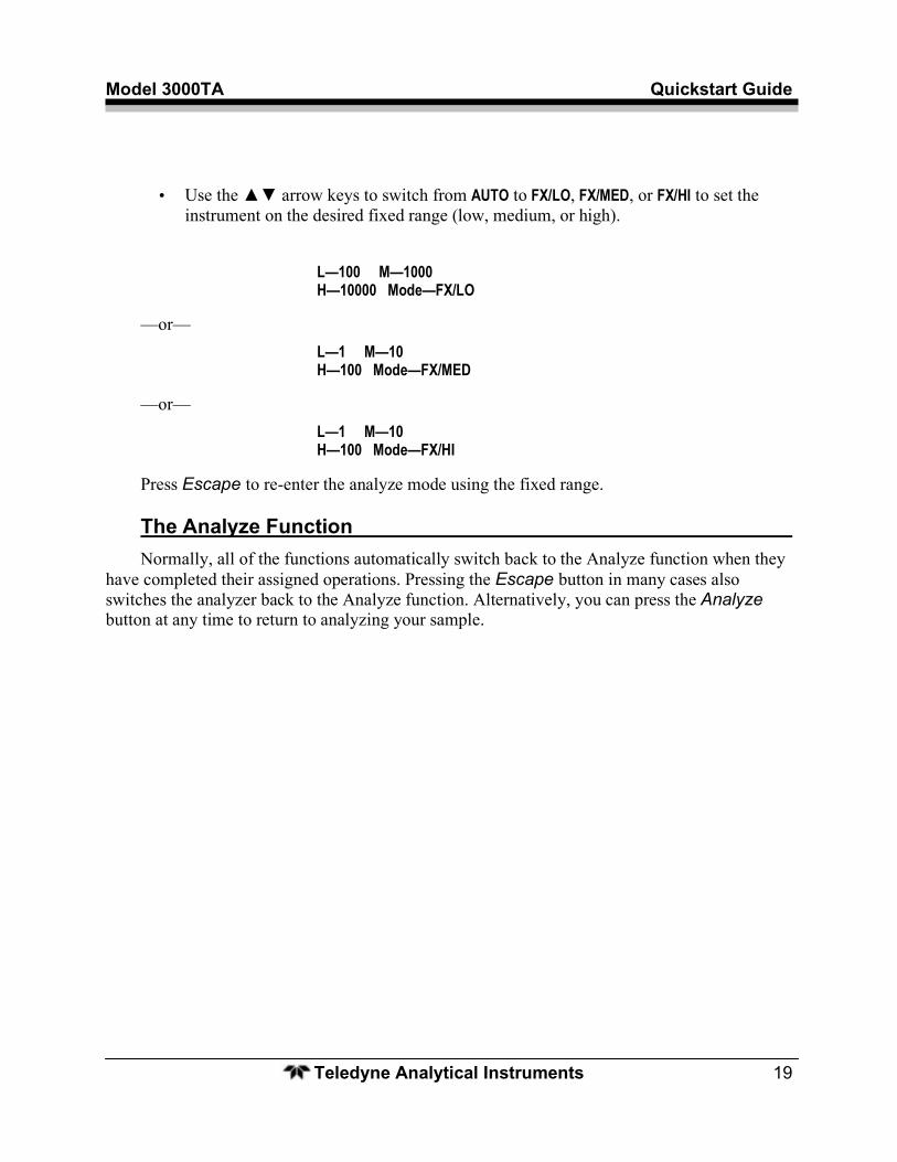
• Use the ▲▼ arrow keys to switch from AUTO to FX/LO, FX/MED, or FX/HI to set the instrument on the desired fixed range (low, medium, or high).
L—100 M—1000 H—10000 Mode—FX/LO
—or— L—1 M—10 H—100 Mode—FX/MED
—or— L—1 M—10 H—100 Mode—FX/HI
Press Escape to re-enter the analyze mode using the fixed range.
The Analyze Function Normally, all of the functions automatically switch back to the Analyze function when they
have completed their assigned operations. Pressing the Escape button in many cases also switches the analyzer back to the Analyze function. Alternatively, you can press the Analyze button at any time to return to analyzing your sample.